


AT91SAM7A3-EK Evaluation Board
..............................................................................................
User Guide

Table of Contents
Section 1
Overview...............................................................................................1-1
1.1 Scope........................................................................................................1-1
1.2 Deliverables ..............................................................................................1-1
1.3 The AT91SAM7A3-EK Evaluation Board..................................................1-1
Section 2
Setting Up the AT91SAM7A3-EK Evaluation Board............................. 2-1
2.1 Electrostatic Warning ................................................................................2-1
2.2 Requirements............................................................................................2-1
2.3 Layout .......................................................................................................2-2
2.4 Powering Up the Board.............................................................................2-3
2.5 Backup Power Supply...............................................................................2-3
2.6 Getting Started..........................................................................................2-3
2.7 AT91SAM7A3-EK Block Diagram .............................................................2-4
Section 3
Board Description ................................................................................. 3-1
3.1 AT91SAM7A3 Microcontroller...................................................................3-1
3.2 AT91SAM7A3 Block Diagram ...................................................................3-4
3.3 Memory .....................................................................................................3-5
3.4 Clock Circuitry...........................................................................................3-5
3.5 Reset Circuitry ..........................................................................................3-5
3.6 Shutdown Controller .................................................................................3-5
3.7 Power Supply Circuitry..............................................................................3-5
3.8 Remote Communication ...........................................................................3-5
3.9 Analog Interface........................................................................................3-5
3.10 User Interface ...........................................................................................3-5
3.11 Debug Interface ........................................................................................3-6
3.12 Expansion Slot ..........................................................................................3-6
Section 4
Configuration Straps .............................................................................4-1
Section 5
Schematics ........................................................................................... 5-1
Section 6
Revision History....................................................................................6-1
AT91SAM7A3-EK Evaluation Board User Guide i
4.1 Configuration Straps .................................................................................4-1
5.1 Schematics ...............................................................................................5-1
6.1 Revision History ........................................................................................6-1
6165C–ATARM–26-Jun-06

Section 1
Overview
1.1 Scope The AT91SAM7A3-EK evaluation kit enables evaluation capabilities and code develop-
ment of applications running on an AT91SAM7A3.
This guide focuses on the AT91SAM7A3-EK board as an evaluation platform.
1.2 Deliverables The AT91SAM7A3-EK package contains the following items:
! an AT91SAM7A3-EK board
! one A/B-type USB cable
! one serial RS232 cable
! one DVD-ROM containing summary and full datasheets, datasheets with electrical
and mechanical characteristics, application notes and getting started documents for
all development boards and AT91 microcontrollers. An AT91 software package with C
and assembly listings is also provided. This allows the user to begin evaluating the
AT91 A R M
®
Thumb® 32-bit microcontroller quickly.
1.3 The
AT91SAM7A3-EK
Evaluation Board
AT91SAM7A3-EK Evaluation Board User Guide 1-1
The board is equipped with an AT91SAM7A3 (100-pin LQFP Green package) together
with the following:
! USB device port interface
! one DBGU serial communication port
! JTAG/ICE debug interface connector
! two serial CAN communication ports
! one serial LIN communication port
! one buffered analog input and PWM output
! one Power LED and four general-purpose LEDs
! one SD/MMC/DataFlash
! expansion connector
! one Atmel
! one footprint for 3.6V lithium thionyl-chloride backup battery
®
®
serial DataFlash
card slot
6165C–ATARM–26-Jun-06

Overview
1-2 AT91SAM7A3-EK Evaluation Board User Guide
6165C–ATARM–26-Jun-06

Section 2
Setting Up the AT91SAM7A3-EK
Evaluation Board
2.1 Electrostatic
Warning
The AT91SAM7A3-EK evaluation board is shipped in a protective anti-static package.
The board must not be subjected to high electrostatic potentials. A grounding strap or
similar protective device should be worn when handling the board. Avoid touching the
component pins or any other metallic element.
2.2 Requirements In order to set up the AT91SAM7A3-EK evaluation board, the following items are
required:
! the AT91SAM7A3-EK evaluation board itself
! an A/B-type USB cable
or
! a DC USB power adapter (5V at 0.5 A) with USB A/B cable
Note: The AT91SAM7A3-EK is not delivered with a JTAG/ICE interface which is
required to start evaluating the device.
AT91SAM7A3-EK Evaluation Board User Guide 2-1
6165C–ATARM–26-Jun-06
Setting Up the AT91SAM7A3-EK Evaluation Board
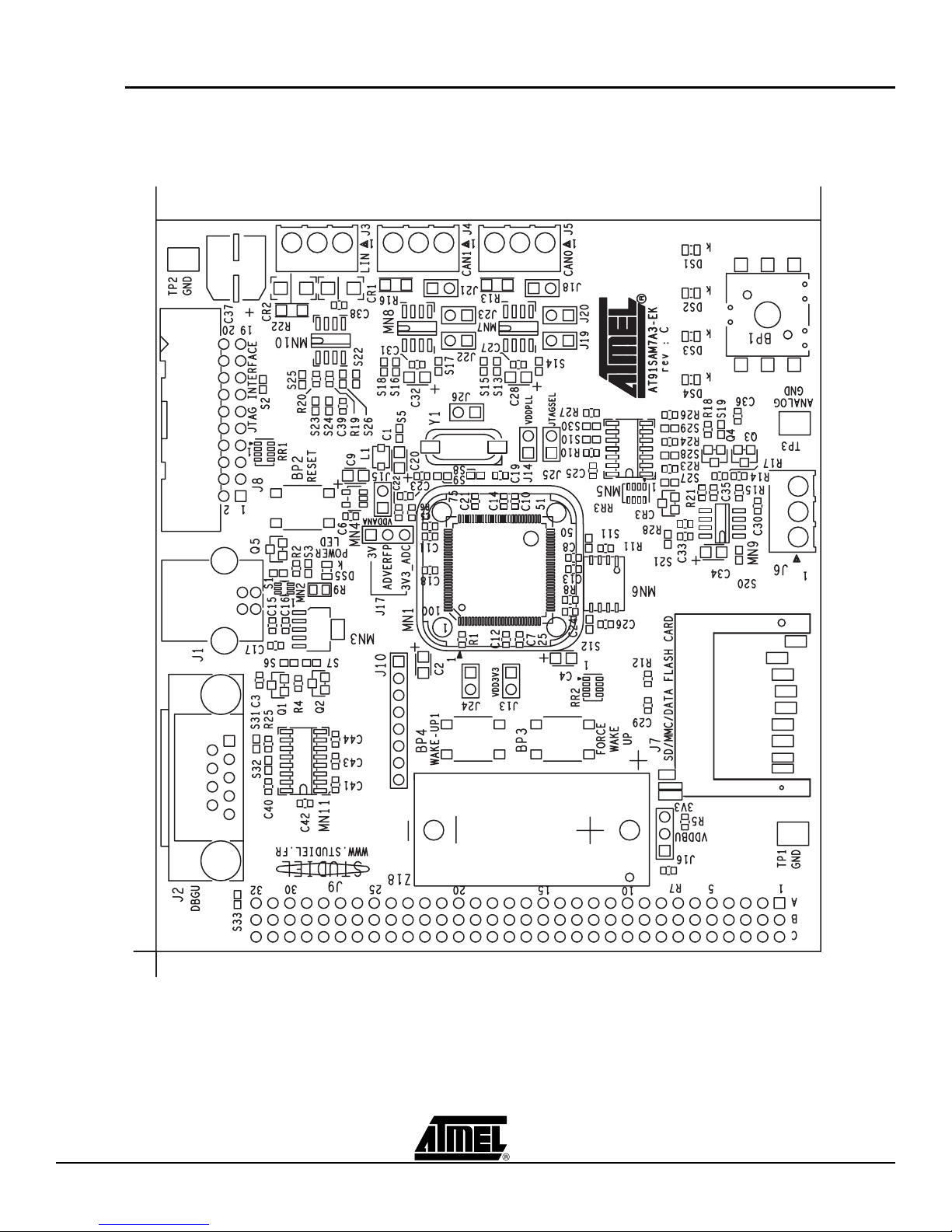
2.3 Layout
Figure 2-1. Top Level Layout
2-2 AT91SAM7A3-EK Evaluation Board User Guide
6165C–ATARM–26-Jun-06

Setting Up the AT91SAM7A3-EK Evaluation Board
2.4 Powering Up the
AT91SAM7A3 is self-powered by the USB port or by a USB power adapter.
Board
2.5 Backup Power
Supply
The user may add a battery (SAFT LS14250 3.6V or equivalent) in order to permanently
power the backup part of the device. In this case, the configuration of J16, S6 and S7
must be changed.
Refer to Table 4-1.
2.6 Getting Started The AT91SAM7A3-EK evaluation board is delivered with a DVD-ROM containing all
necessary information and step-by-step procedures for working with the most common
development tool chains. Please refer to this DVD-ROM, or to the Atmel web site,
http://www.atmel.com/products/AT91/, for the most up-to-date information on getting
started with the AT91SAM7A3-EK.
Note that the AT91SAM7A3 microcontroller fitted on the evaluation board has been pro-
grammed with the SAM Boot Assistant (SAM-BA
program the embedded Flash memory through the USB or DBGU communication
channel.
Programming through DBGU requires that the evaluation kit is powered using a Power
Supply USB Adapter
™
) which provides an easy way to
Note: The SAM-BA Boot Assistant resides in the embedded Flash memory and will be
deleted when programming the Flash. A JTAG/ICE interface is required to recover
SAM-BA Boot Assistant.
AT91SAM7A3-EK Evaluation Board User Guide 2-3
6165C–ATARM–26-Jun-06
Setting Up the AT91SAM7A3-EK Evaluation Board
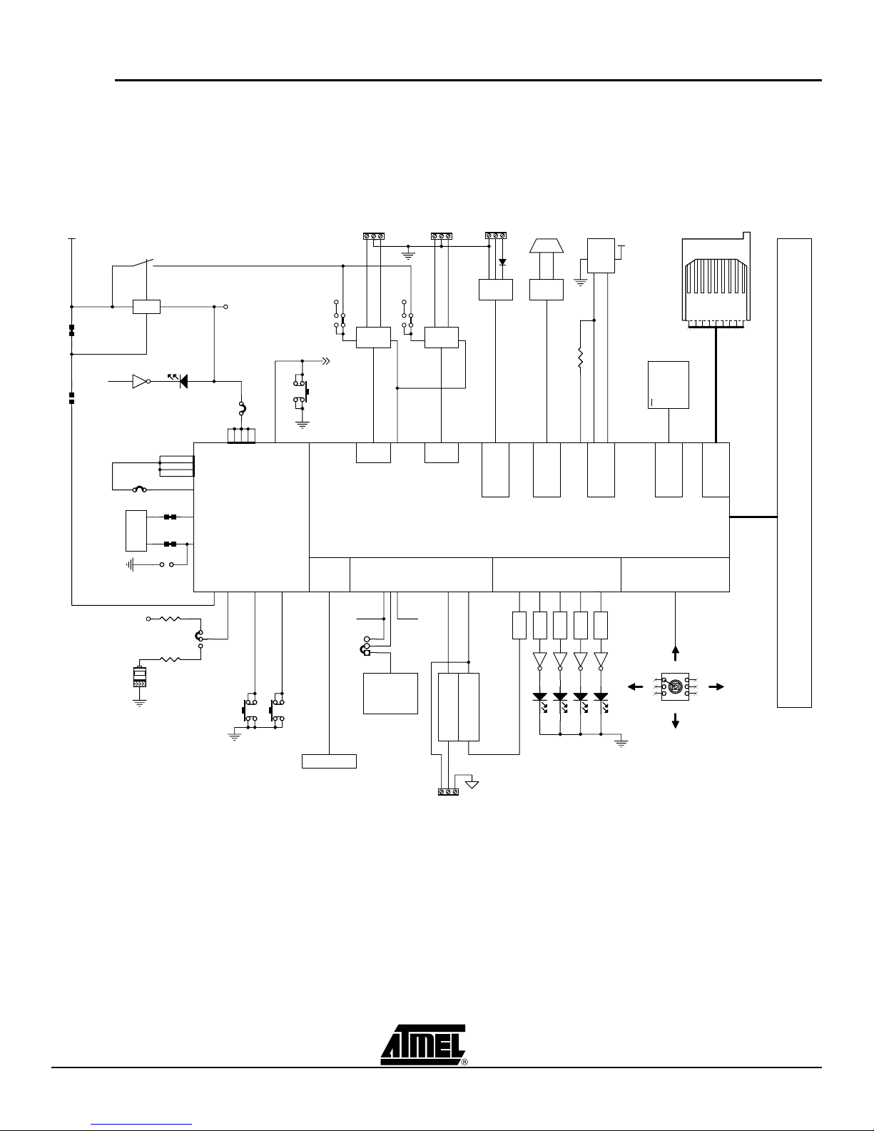
2.7 AT91SAM7A3-EK
Block Diagram
Figure 2-2. Block Diagram
VBUS
S6S6
S7S7
IN OUT
3.3V
nSHUTDOWN
YELLOWYELLOW
PIO
LIGHTED WHEN POWER ON
J14J14
18.432 MHz
POWER LED
VDDPLL
J26J26
3V3
VDD1V8
SYSTEM CONTROLLER
XOUT
XIN
SHDN
VDDBU
J13J13
VDD3V3
FORCE WAKE-UP
NRST
WAKE-UP1
3V3
5V
NRST
BP2BP2
MANUAL RESET
JTAG/ICE
J5 J4 J3
CANL1CANH
TJA1050
CAN0
RS
CANL1CANH
3V3
5V
TJA1050
RS
CAN1
PIO
AT91SAM7A3-LQFP100
ADC
GNDANA
VDDANA
ADVREFP
ADC0_AD3
LIN
ATA6661
MN18
ADC0_AD2
1
USART0
DBGU
RS232
J2
TXD
RXD
ADM3202A
DRXD - DTXD
DBGU
PWM0..PWM7
USB DEVICE
1K51K5
DDP
PIO
SD/MMC
DATAFLASH (NPCS03)
ATMEL
SERIAL
DATAFLASH
CS
SPI0
PIO BEXT CLK INPUT
CARD READER
J7
8 57 6 4 3 2 1 9
MCI
VBUS
J1
DDM
USB
J9
PIO BPIO A
PIO A - PIO B EXPANSION CONNECTOR
3V3
R18 470RR18 470R
VDD BACKUP SELECT
R20
R20
3.6V
3.6V
3V6
3V6
NOT POPULATED
470R
470R
GNDANA
3
2
J16J16
1
BP3BP3
BP4BP4
JTAG/ICE CONNECTOR
3.3VANA
PWM2
PWM6
PWM7
PWM3
3
2
1
J17J17
3.00V +- 0.2%
EXTERNAL REF
0 TO VREF
0 TO VREF
EXTERNAL INPUT
PWM VOLTAGE GEN.
J8
1
J6
ANALOG INPUT
PWM0
DS1DS1 DS2DS2
DS3DS3
USER'S GREEN LED
DS4DS4
1
4
52
3 6
BP1BP1
USER'S TACT SWITCH
2-4 AT91SAM7A3-EK Evaluation Board User Guide
6165C–ATARM–26-Jun-06
 Loading...