


Asus X2124X User Manual

GigaX Series
Layer 2 Managed Switch
User Guide

GigaX Series L2 Managed Switch User Guide
E1367
First Edition V1
March 2005
Copyright © 2005 ASUSTeK COMPUTER INC. All Rights Reserved.
No part of this manual, including the products and softw are described in it, may be reproduced,
transmitted, transcribed, stored in a retrieval system, or tran slated into any language in any form or
by any means, except documentation kept by the purcha ser for backup purpo ses, without the
express written permission of ASUSTeK COMPUTER INC. (ASUS) .
Product warranty or service will not be extended if: (1) the pr oduct is rep aired, modif ied or altere d,
unless such repair, modification of alterat ion is author ized in writing by ASUS; or (2) the se rial
number of the product is defaced or missing.
ASUS provides this manual "as is" without warranty of any kind, either express or implied, including
but not limited to the implied warranties or conditi ons of merchantab ility or fitness for a par ticular
purpose. In no event shall ASUS, its directors, officer s, employ ees, or agents be liable fo r any
indirect, special, incidental, or con sequential damages (includ ing damages for loss of profit s, loss of
business, loss of use or data, interr uption of business and the like), even if ASUS has bee n advised
of the possibility of such damages arising from any defect or error in th is manual or produ ct.
Specifications and information contained in th is manual are furnished for informat ional use only,
and are subject to change at any time without notice, a nd should not be construed as a commitment
by ASUS. ASUS assumes no responsibility or liab ility for any errors or inaccuracies that may
appear in this manual, including the products and software described in it.
Products and corporate names appearing in this manual may or may not be regist ered trademarks
or copyrights of their respective companie s, and are used only for iden tification or explanat ion and
to the owners' benefit, without intent to infrin ge.
2

GigaX Series L2 Managed Switch User’s Guide
Federal Communications Commission Statement
This device complies with Part 15 of the FCC Rules. Operation is subject to the
following two conditions:
• This device may not cause harmful interference, and
• This device must accept any interference received including interference
that may cause undesired operation.
This equipment has been tested and found to comply with the limits for a Class
B digital device, pursuant to Part 15 of the FCC Rules. These limits are
designed to provide reasonable protection agai nst harmful interf erence in a
residential installation. This equipment generates, uses and can radiate radio
frequency energy and, if not installed and used in accordance with
manufacturer's instructio ns, may cause harmful int erfere nce to radio
communications. However, there is no gua rantee that interfe rence will not
occur in a particular installation. If this equipment does cause harmful
interference to radio or telev isio n reception , which ca n be det ermine d by
turning the equipment off and on, the user is encouraged to try to correct the
interference by one or more of the follo wing mea sures:
• Reorient or relocate the receiving antenna.
• Increase the separation between the equipment a nd receiver.
• Connect the equipment to an outlet on a circuit different from that to which
the receiver is connected.
• Consult the dealer or an experienced radio/TV technician for help.
WARNING! The use of shielded cables for connection of the monitor to the
graphics card is required to assure compliance with FCC regulations. Changes
or modifications to this unit not expressly approved by the party responsible for
compliance could void the user's aut hority to op erate this equipme nt.
Canadian Department of Communications Statement
This digital apparatus doe s not ex ceed the Class B li mits f or radi o noise
emissions from digital apparatus set out in the Radio Interference Regulations
of the Canadian Department of Communication s.
This class B digital apparatus complies with Canadian ICES-003.
3

GigaX Series L2 Managed Switch User Guide
ASUS contact information
ASUSTeK COMPUTER INC. (Asia-Pacific)
Address: 150 Li-Te Road, Peitou, Taipei, Taiwan 112
General Tel: +886-2-2894-3447
General Fax: +886-2-2894-7798
Web Site: www.asus.com.tw
Technical Support
MB/Others (Tel): +886-2-2890-7121 (English)
Notebook (Tel): +886-2-2890-7122 (English)
Desktop/Server (Tel): +886-2-2890-7123 (English)
Support Fax: +886-2-2890-7698
ASUS COMPUTER INTERNATIONAL (America)
Address: 44370 Nobel Drive, Fremont, CA 94538, USA
General Fax: +1-502-933-8713
General Email: tmd1@asus.com
Web Site: usa.asus.com
Technical Support
Support Fax: +1-502-933-8713
General Support: +1-502-995-0883
Notebook Support: +1-510-739-3777 x5110
Support Email: tsd@asus.com
ASUS COMPUTER GmbH (Germany and Austria)
Address: Harkort Str. 25, D-40880 Ratingen, BRD, Germany
General Fax: +49-2102-9599-31
General Email: sales@asuscom.de (for marketing requests only)
Technical Support
Support Hotlines: (Components) +49-2102-95990
(Notebook PC) +49-2102-959910
Support Fax: +49-2102-959911
Support Email: www.asuscom.de/de/support (for online support)
Web Site: www.asuscom.de
ASUS COMPUTER (Middle East and North Africa)
Address: P.O. Box 64133, Dubai, U.A.E.
General Tel.: +9714-283-1774
General Fax: +9714-283-1775
General Email: www.ASUSarabia.com
4

GigaX Series L2 Managed Switch User Guide
Table of Contents
1.1 L2 managed features.....................................................11
1.2 Conventions used in this document...............................12
1.2.1 Notations.........................................................12
1.2.2 Typography.....................................................12
1.2.3 Symbols..........................................................12
2.1 Package contents...........................................................13
2.2 Front Panel.....................................................................14
2.3 Rear Panel.....................................................................16
2.4 Technical specifications.................................................17
3.1 Part 1 — Installing the hardware....................................18
3.1.1 Installing the switch on a flat surface..............18
3.1.2 Mounting the switch on a rack........................18
3.2 Part 2 — Setting up the switch.......................................19
3.2.1 Connect the console port................................19
3.2.2 Connect to the computers or a LAN...............19
3.2.3 Attach the RPS module ..................................19
3.2.4 Attach the power adapter................................19
3.3 Part 3 — Basic switch setting for management.............21
3.3.1 Setting up through the console port................21
3.3.2 Setting up through the Web interface.............23
4.1 Log into Web user interface...........................................25
4.2 Functional layout............................................................27
4.2.1 Menu navigation tips.......................................29
4.2.2 Commonly used buttons and icons ................29
4.3 System Pages................................................................30
4.3.1 Management...................................................30
4.3.2 IP Setup..........................................................31
4.3.3 Administration.................................................32
4.3.4 Reboot ............................................................33
5

GigaX Series L2 Managed Switch User Guide
Firmware Upgrade..........................................33
4.3.5
4.4 Physical Interface ..........................................................35
4.5 Bridge.............................................................................37
4.5.1 Spanning Tree ................................................37
4.5.2 Link Aggregation.............................................38
4.5.3 Mirroring..........................................................40
4.5.4 Static Multicast................................................42
4.5.5 IGMP Snooping...............................................43
4.5.6 Traffic Control .................................................43
4.5.7 Dynamic Addresses........................................44
4.5.8 Static Addresses.............................................46
4.5.9 Tagged VLAN .................................................47
4.5.10 Default Port VLAN and CoS............................49
4.5.11 CoS Queue Mapping ......................................50
4.6 SNMP.............................................................................51
4.6.1 Community Table............................................51
4.6.2 Host Table.......................................................52
4.6.3 Trap Setting ....................................................53
4.6.4 VACM Group...................................................53
4.6.5 VACM View.....................................................54
4.6.6 USM User........................................................56
4.7 Security...........................................................................58
4.7.1 Port Access Control........................................58
4.7.2 Dial-In User.....................................................59
4.7.3 RADIUS...........................................................60
4.8 VCT ................................................................................62
4.9 Statistics Chart ...............................................................63
4.9.1 Traffic Comparison..........................................63
4.9.2 Error Group.....................................................63
4.9.3 Historical Status..............................................64
4.10 Save Configuration.........................................................65
6

GigaX Series L2 Managed Switch User Guide
Power On Self Test........................................................67
5.1
5.1.1 Boot ROM Command Mode ...........................68
5.1.2 Boot ROM Commands....................................69
5.2 Login and Logout ...........................................................70
5.3 CLI Commands..............................................................70
5.3.1 System Commands ........................................70
5.3.2 Physical Interface Commands........................73
5.3.3 Bridge Commands..........................................74
5.3.4 SNMP..............................................................82
5.3.5 Security Commands .......................................90
CLI command : security sshkey show............................93
5.4 Miscellaneous Commands.............................................94
6.1 IP Addresses..................................................................95
6.1.1 Structure of an IP address..............................95
6.1.2 Network classes..............................................97
6.2 Subnet masks ................................................................98
7.1 Diagnosing problems using IP utilities.........................100
7.1.1 ping...............................................................100
7.1.2 nslookup .......................................................102
7.2 Replacing defective fans..............................................103
7.3 Simple fixes..................................................................105
7

GigaX Series L2 Managed Switch User Guide
List of Figures
Figure 1. GigaX L2 managed switch package contents................13
Figure 2. Front panel .....................................................................14
Figure 3. Rear panel......................................................................16
Figure 4. Overview of Hardware Connections...............................20
Figure 5. Login and IP setup Screen.............................................22
Figure 6. Login Screen..................................................................23
Figure 7. IP Setup..........................................................................24
Figure 8. Configuration manager login screen..............................25
Figure 9. Home page.....................................................................26
Figure 10. Top frame.......................................................................27
Figure 11. Expanded Menu List.......................................................28
Figure 12. Management ..................................................................30
Figure 13. IP Setup..........................................................................31
Figure 14. Administration.................................................................32
Figure 15. Firmware Upgrade..........................................................34
Figure 16. Physical Interface...........................................................36
Figure 17. Spanning Tree................................................................38
Figure 18. Link aggregation.............................................................40
Figure 19. Mirroring page ................................................................41
Figure 20. Static Multicast ...............................................................42
Figure 21. IGMP Snooping..............................................................43
Figure 22. Traffic Control.................................................................44
Figure 23. Dynamic Address...........................................................45
Figure 24. Static Address ................................................................46
Figure 25. Tagged VLAN.................................................................48
8

GigaX Series L2 Managed Switch User Guide
Figure 26.
Figure 27. 50
Figure 28. Community Table...........................................................51
Figure 29. Host Table......................................................................52
Figure 30. Trap Setting....................................................................53
Figure 31. VACM Group..................................................................54
Figure 32. VACM View....................................................................55
Figure 33. USM User.......................................................................57
Figure 34. Port Access Control .......................................................59
Figure 35. Dial-In user.....................................................................60
Figure 36. RADIUS..........................................................................61
Figure 37. VCT................................................................................62
Figure 38. Traffic comparison..........................................................63
Figure 39. Error group.....................................................................64
Figure 40. Historical Status.............................................................64
Figure 41. Save Configuration.........................................................65
Default Port VLAN and CoS...........................................49
Cos Queue Mapping ...................................................................50
Figure 42. CLI interface...................................................................67
Figure 43. Boot ROM Command Mode...........................................68
Figure 44. SYS commands .............................................................71
Figure 45. Using the ping utility.....................................................101
Figure 46. Using the nslookup utility.............................................102
Figure 47. Loosening the thumbscrew..........................................103
Figure 48. Removing the fan module............................................103
Figure 49. Detaching the fan from the module..............................104
9

GigaX Series L2 Managed Switch User Guide
List of Tables
Table 1. Front panel labels and LEDs..........................................15
Table 2. Rear panel labels ...........................................................16
Table 3. Technical specifications .................................................17
Table 4. LED Indicators................................................................21
Table 5. Port color description......................................................27
Table 6. Commonly used buttons and icons................................29
Table 7. Boot ROM commands....................................................69
Table 8. IP address structure.......................................................96
Table 9. Troubleshooting............................................................105
10

GigaX Series L2 Managed Switch User Guide
1 Introduction
Congratulations on becoming the owner of the ASUS GigaX L2 managed
switch! You may now manage your LAN (local area network) through a
friendly and powerful user interface.
This user guide tells you how to set up the GigaX L2 managed switch, and
how to customize its configuration to get the most out of this product.
1.1 L2 managed features
• 24 10/100/1000BASE-TX auto-sensing Fast Ethernet ports
• Four small form factor (SFP) Gigabit interf ace converte r (GBIC) slot s
• 802.1D transparent bridge/spanning tree protocol
• 8K MAC address cache with hardware-assisted aging
• 802.3x flow control
• 802.1Q-based tagged VLAN , up to 25 5 VLANs
• 802.1p class of service, 4 queues per port
• IGMP snooping support
• 802.3ad link aggregation (manual and LACP), up to 31 trunk groups
• Port Mirroring
• 802.1w RSTP
• 802.1x and RADIUS
• RMON: support 4 groups (1, 2, 3, 9)
• SNMP v1, v2, v3
• MIB-II
• Enterprise MIB for PSU, fan, and sy stem tem perature, v oltage
• Telnet or SSH remote login
• FTP for firmware update and configuration backup
• Syslog.
• Command Line Interpreter through con sole , telnet and SSH
• Web GUI
• LEDs for port link status
11

GigaX Series L2 Managed Switch User Guide
• LEDs system, redundant power supply (RPS), and fa n status
1.2 Conventions used in this document
1.2.1 Notations
• Acronyms are defined the first time they appear in text an d in the glossary.
• For brevity, the GigaX switch is referred to as “the switch.”
• The terms LAN and network are used interchangeably to refer to a group
of Ethernet-connected computers at one site.
1.2.2 Typography
• Italics are used to present the parameters for the command line
interpreter.
• Boldface type text is used for items you select from menu s and drop-down
lists, and text strings you ty pe when prompte d by the prog ram.
1.2.3 Symbols
This document uses the following icons to call your attention to specific
instructions or explanations.
Provides clarification or additional information on the current
Note
topic.
Definition
WARNING
12
Explains terms or acronyms that may be unfamiliar to many
readers. These terms are also included in the Glossary.
Provides messages of high importance, including messages
relating to personal safety or system integrity.
GigaX Series L2 Managed Switch User Guide
2 Getting to know the GigaX 2124X
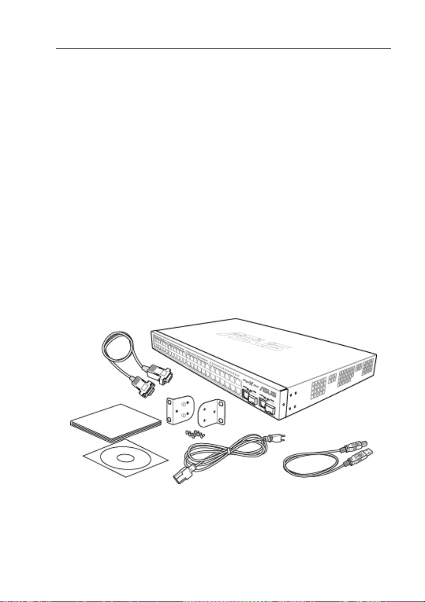
2.1 Package contents
The GigaX 2124X switch package comes with the following items:
• GigaX 2124X (24-port) L2 managed switch
• AC Power cord
• Null modem cable for console interface (DB9)
• Rack installation kit (two brackets with six #6-32 screws)
• USB cable for console interface
• Installation CD-ROM
• User Manual
• Quick installation guide
Figure 1. GigaX L2 managed switch package contents
13
GigaX Series L2 Managed Switch User Guide
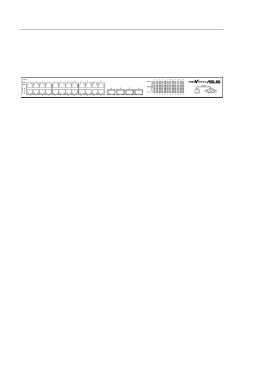
2.2 Front Panel
The front panel includes LED indicators that show the system, RPS, fan,
and port status.
Figure 2. Front panel
14
GigaX Series L2 Managed Switch User Guide
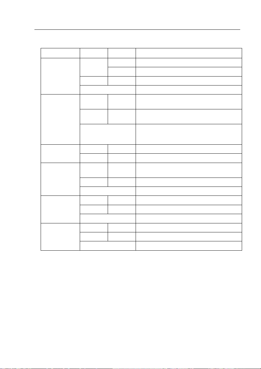
Table 1. Front panel labels and L E Ds
Label Color Status Description
SYSTEM
RPS
10/100/1000
port status
10/100/1000
port speed
10/100/1000
port duplex
Amber On Abnormal temperature or voltage
Off No power
Green On The PSU is working properly and the switch
Amber On The PSU is abnormal and the switch is
Off No power at all (system LED is also off), RPS
Green On Both fans are working properly FAN
Amber On Both or either one of the fans stopped
Green On Link (RJ-45 or SFP) is present; port is
Flashing Data is being transmitted/received
Off No Ethernet link
Green On 1000Mbps
Amber On 100Mbps
Off 10Mbps or link is not present
Green On Full duplex
Amber On Half dulplex
Off Link is not present
On Unit is powered on Green
Flashing Self-test, INIT, or downloading
has a good redundant power supply
powered by RPS
does not work properly or not installed
(system LED is on)
enabled
15
GigaX Series L2 Managed Switch User Guide
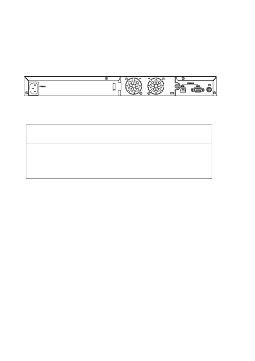
2.3 Rear Panel
The switch rear panel contains the ports for the data and power
connections.
Figure 3. Rear panel
Table 2. Rear panel labels
No. Label Description
1 Power Connector Connects to the supplied power cord
2 FAN1 – FAN2 Replaceable system fans
3 Console USB USB port for console management
4 Console RS232 RS-232 serial port for console management
5 RPS Redundant Power Supply connector
16
GigaX Series L2 Managed Switch User Guide
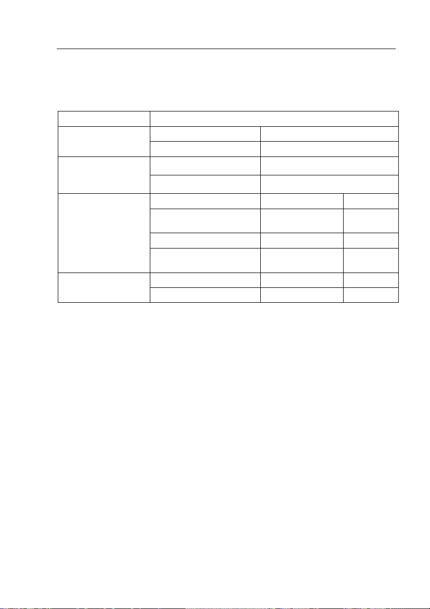
2.4 Technical specifications
Table 3. Technical specifica tions
Physical Dimensions 43.5mm(H) X 444 mm(W) X 265mm(D)
Input Consumption Power
100-240V AC/2.5A 50-60Hz < 90 watts
Supply (RPS)
Input Output Redundant Power
100-240V AC/1.8A 50-60Hz 12V DC/12.5A
Environmental Ranges
Operating Storage
Temperature -10 to 50 (14 to ℃
122 )℉
Humidity 15 to 90% 0 to 95%
Altitude up to 10,000 ft
(3,000m)
Dimensions Voltage and Current Speed: Replaceable Fans
40 x 40 x 20 mm 12VDC, 0.13A 8200RPM
-40 - 70℃
(-40 to 158 )℉
40,000 ft
(12,000m)
17

GigaX Series L2 Managed Switch User’s Guide
3 Quick start guide
This section provides the basic instructions to set up the GigaX environment.
Refer also to the GigaX Series Installation Guide.
Part 1 shows you how to install the GigaX on a flat surface or on a rack.
Part 2 provides instructions to set up the hardware.
Part 3 shows you how to configure basic settings on the GigaX.
Obtain the following inf orma tion fro m your net work ad ministrat or bef ore
proceeding:
IP address for the switch
Default gateway for the network
Network mask for this network
3.1 Part 1 — Installing the hardware
Connect the device to the power outlet, and your computer or network.
Figure 4 illustrates the hardware connections.
3.1.1 Installing the switch on a flat surface
The switch should be installed on a lev el surface that can support the weight of
the switches and their accessories. Attach four rubber pads on the marked
location on the bottom of the switch.
3.1.2 Mounting the switch on a rack
1. Attach brackets to each side of the switch and make the posts insert to
the switch.
2. Insert and tighten two screws to securely attach the bracket to the rack
on each side.
18

GigaX Series L2 Managed Switch User Guide
3.2 Part 2 — Setting up the switch
Connect the device to the power outlet, and your computer or network. See
Figure 4.
3.2.1 Connect the console port
For console management, use an RS232 (DB9) or a USB cable to connect
the switch. If you want to use WEB interface, connect your PC to the switch
using the Ethernet cable.
3.2.2 Connect to the computers or a LAN
You can use Ethernet cable to connect computers dire ctly to the switch ports.
You can also connect hubs/switches to the switch ports by Ethernet cables.
You can use either the crossover or straight-through Ethernet cable to connect
computers, hubs, or switches.
Use a twisted-pair Category 5 Ethernet cable to connect the
1000BASE-T port. Otherwise, the link speed can not reach
1Gbps.
3.2.3 Attach the RPS module
Connect your RPS module to the RPS jack and make sure the other end of the
RPS is connected to the power cord. Connect to the power cord to a grounded
power outlet.
3.2.4 Attach the power adapter
1. Connect the AC power cord to the POWER receptacle on the back of
the switch and plug the other end of the power cord into a wall outlet or
a power strip.
2. Check the front LED indicators with the description in Table 4. If the
LEDs light up as described, the switch hardware is working properly.
19
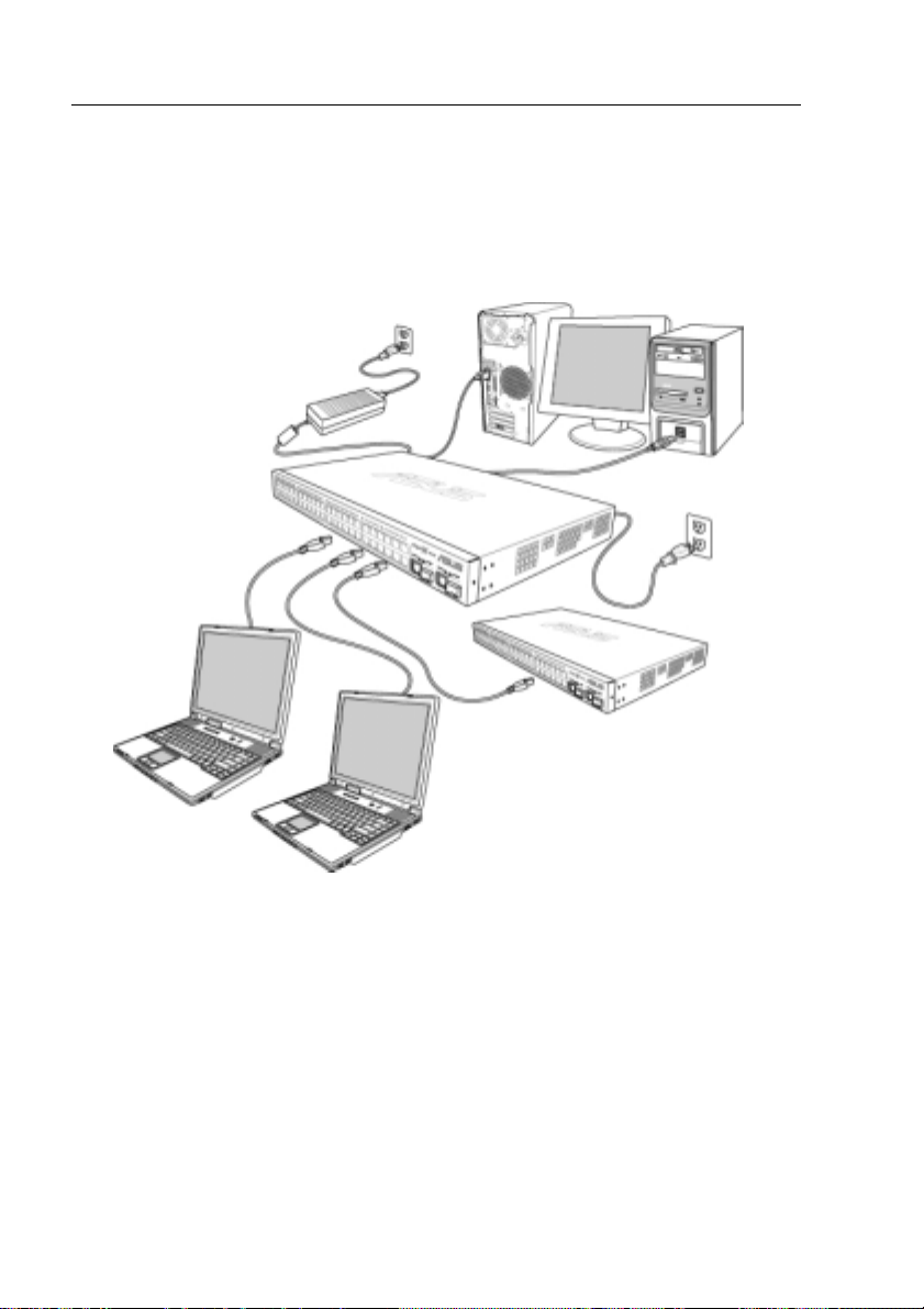
GigaX Series L2 Managed Switch User’s Guide
Cat 5 Ethernet cables
LAN computers
Figure 4. Overview of Hardware Connections
RPS
RS-232
Console
Management
USB
Expansion
hub/switch
20
GigaX Series L2 Managed Switch User Guide
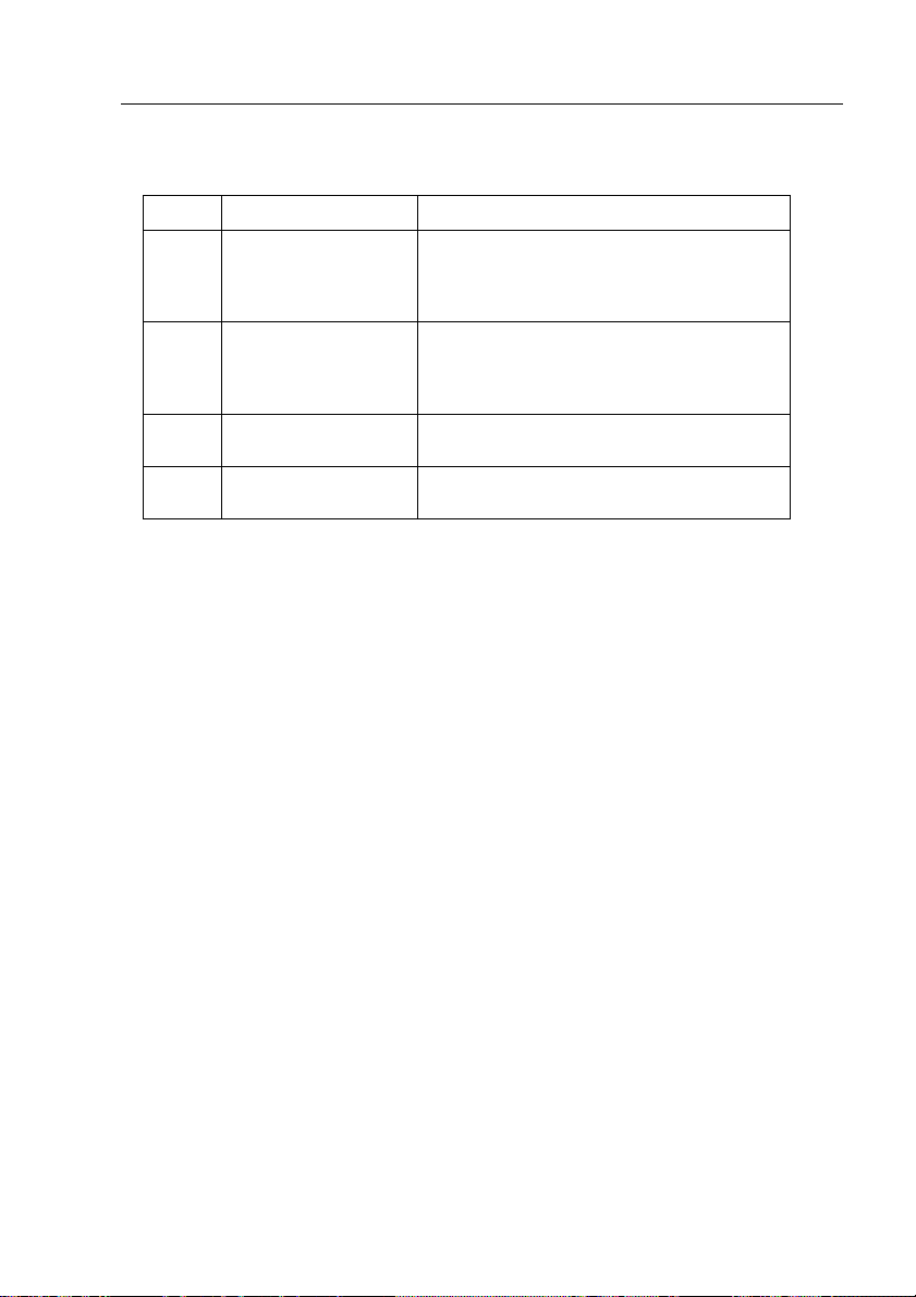
Table 4. LED Indicators
No. LED Description
1 System Solid green indicates that the device is turned
2 Switch ports
[1] to [24]
3 RPS Solid green indicates that the device has
4 Fan Solid green indicates that all fans work
on. If this light is off, check if the power
adapter if attached to the switch and plugged
into a power source.
Solid green indicates that the device can
communicate with the LAN, or flashing when
the device is sending or receiving data from
your LAN computer.
successfully installed an RPS module.
properly
3.3 Part 3 — Basic switch setting for
management
After completing the hardware connections, configure the basic settings for
your switch. You can manage the switch using the following methods:
• Web interface: the switch has a set of pages to allow to you manage it
using Java
®
-enabled IE5.0 or higher version.
• Command Line Interface: use console port to manage the switch.
3.3.1 Setting up through the console port
1. Use the supplied crossover RS-232 cable to connect to the console
port on the back of the switch. This port is a male DB-9 connector,
implemented as a data terminal equipment (DTE) connection. Tighten
the retaining screws on the cable to secure it on the connector.
Connect the other end of the cable to a PC running terminal emulation
software. e.g Hyper Terminal.
2. Use the supplied USB cable to connect to a PC. You have to install the
USB driver from the switch CD-ROM before the USB can work properly.
The USB drivers will simulate an additional COM port under Windows
Me/2K/XP OS.
21
GigaX Series L2 Managed Switch User’s Guide
3. Make sure the settings of your terminal emulation software as follows:
a) Choose the appropriate serial port number
b) Set the data baud rate to 9600
c) Set the data format to no parity, 8 data bits and 1 stop bit
d) No flow control
e) Set VT1000 for emulation mode
4. After setting up the terminal, you can see the prompt “(ASUS)%” on the
terminal.
5. Type “login” to access the command line interface. The default user
name is “admin”. Skip the password by pressing <Enter>.
You can change the password at any time through CLI (see
section 5.3.1). To protect your switch from unauthorized
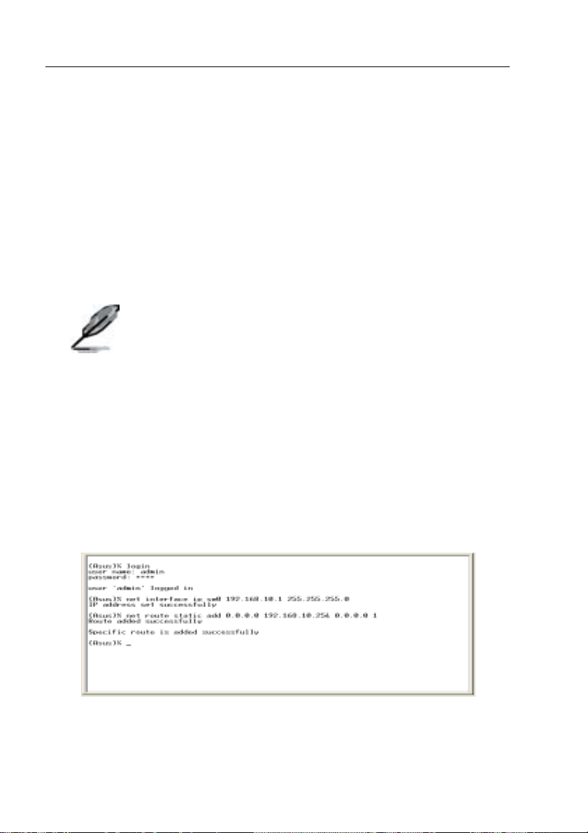
6. Follow these steps to assign an IP address to the switch:
a) Type “net interface ip sw0 <your ip address> <your network
mask>”. For example, if your switch IP is 192.168.10.1 and the
network mask is 255.255.255.0. Then you should type “net
interface ip sw0 192.168.10.1 255.255.255.0”.
access, you must change the default password as soon as
possible.
b) If the switch has to be managed across networks, then a default
gateway or a static route entry is required. Type “net route static
add 0.0.0.0 <your network gateway IP> 0.0.0.0 1// as your default
route entry, as shown in Figure 5.
Figure 5. Login and IP setup Screen
22
GigaX Series L2 Managed Switch User Guide
3.3.2 Setting up through the Web interface
To successfully connect your PC to the switch, your PC must a valid IP in your
network. Contact your network admini strator t o obtai n a valid IP f or the switch.
If you wish to change the default IP address of the swit ch, follow secti on 3.3.1
to change the IP address. Since the switch does not support DHCP client
function, a valid static IP for the switch i s necessary to u se Web int erface.
1. It is not necessary to login Web interface at the first time to use Web
interface because the default configuration for Web access
authentication is disabled. To secure the system configuration, please
enable the authentication function at the “Administration” page under
“System” category. Skip step 2 if the authentication is disabled.
2. At any PC connected to the network that the switch can access , open
your Web browser (Internet Explorer), and type the following URL in the
address/location box, and press <Enter>:
http://192.168.1.1
This is the factory default IP address of the switch.
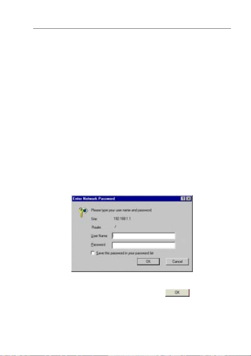
A login screen appears, as shown in Figure 6.
Figure 6. Login Screen
Enter your user name and password, a nd then cli ck
Configuration Manager. Use the following defaults the first time you log into
this interface:
to enter the
23
GigaX Series L2 Managed Switch User’s Guide
Default User Name: Admin
Default Password: (no password)
You can change the password at any time (see section
5.3.1 System Commands).
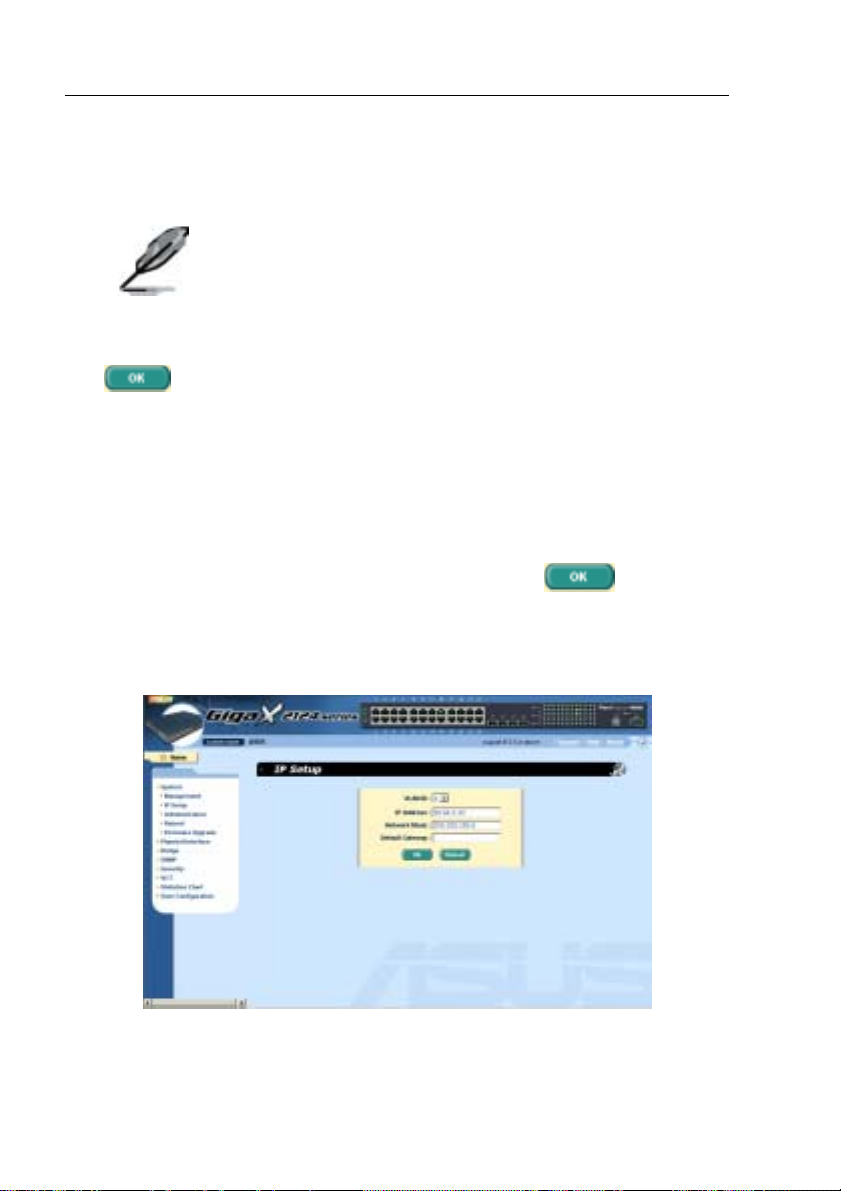
3. To setup a new IP address, click “System”, then “IP Setup” (see Figure
8). Fill in the IP address, network mask and default gateway, then click
.
4. If your new address is different from the default, the browser can not
update the switch status window or retrieve any page. This is normal.
You have to retype the new IP address in the address/location box, and
press <Enter>. The WEB link returns.
5. To enable authentication for Web access, click “Administration” on
the menu list, then select “Enabled” to start the protection.
A login window appears i mmedi ately afte r you cl ick
figures on the next page.
Figure 7. IP Setup
24
. See the
GigaX Series L2 Managed Switch User Guide
4 Management with the Web Interface
The switch provides Web pages that al low swit ch manag ement throug h the
Internet. The program is designed to work best with Microsoft Internet
Explorer® 5.5, or later versions. NOTE: Netscape is not supported.
4.1 Log into Web user interface
1. From a PC, open your web browser, type the following in the web
address (or location) box, and press <Enter>:
http://192.168.1.1
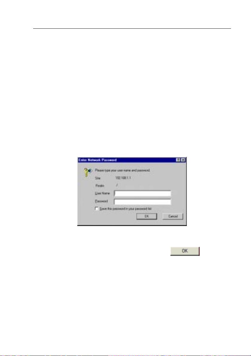
This is the factory default IP address f or t he switch. A l ogin screen
displays, as shown in Figure 8.
Figure 8. Configuration manager login screen
2. Enter your user name and password, then click
Use the following defaults the first time yo u log int o the pro gram. You can
change the password at any time through CLI interface (see sectio n
5.3.1 )
Default User Name:
Default Password:
admin
<no password>
.
25
GigaX Series L2 Managed Switch User’s Guide
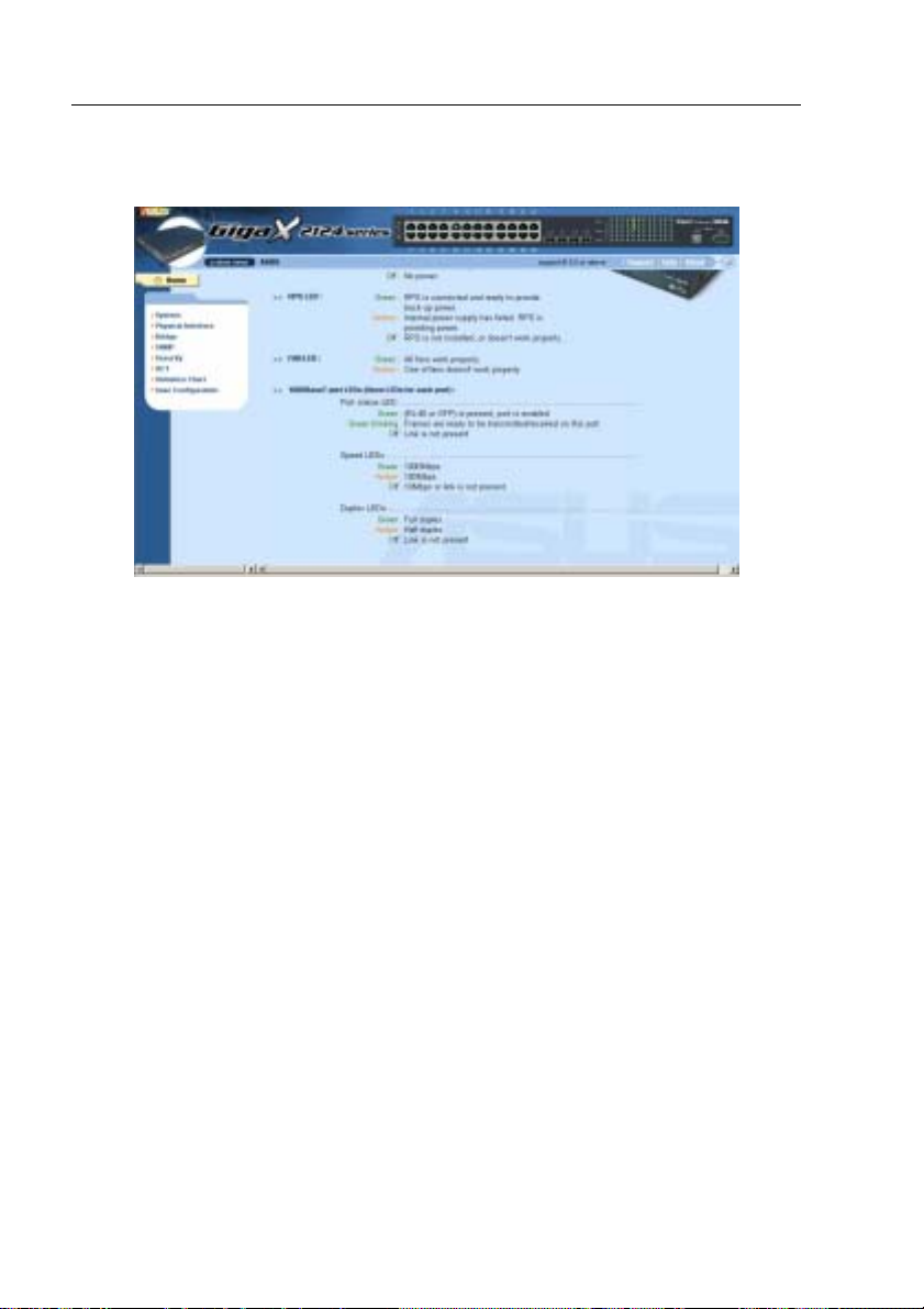
The home page appears each tim e you log int o the prog ram. (See Figures 9).
Figure 9. Home page
26
GigaX Series L2 Managed Switch User Guide
4.2 Functional layout
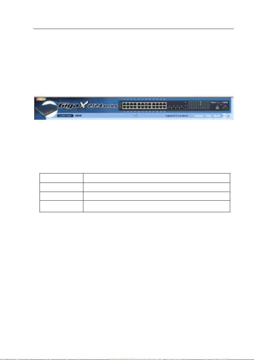
Typical web page consists of three separate frames. The top frame has a
switch logo and front panel as shown in Figures 10. This frame remains on the
top of the browser window all the times and updates the LED status
periodically. See Table 4 for the LED definition s. See Table 5 for the col or
status description.
Figure 10. Top frame
Table 5. Port color description
Port Color Description
Green port Ethernet link is established
Black No Ethernet link
Amber port Link is present but port is disabled manually or by spanning tree
Clicking on the port icon of t he switch display s the port config uratio n in the
lower right frame.
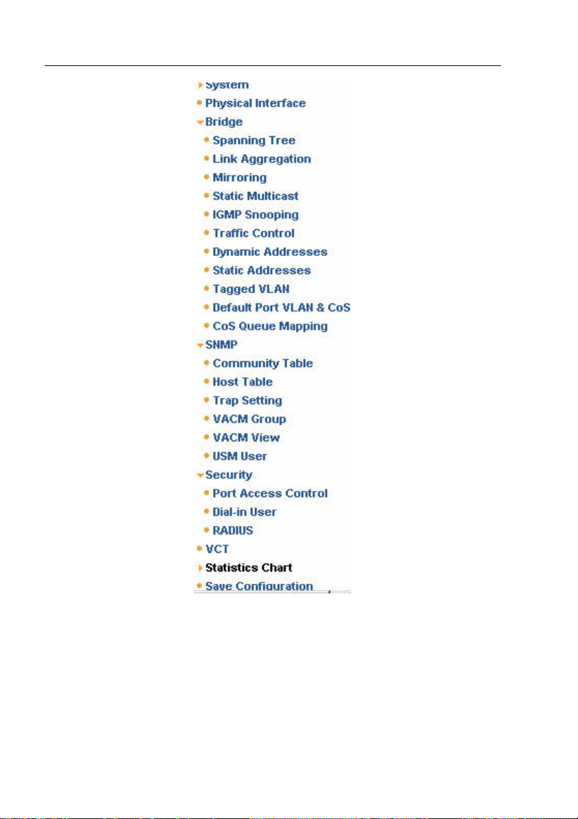
The left frame, a menu frame as shown in Figure 11, contains all the features
available for switch configuration. Th ese featu res are group ed into catego ries,
e.g. System, Bridge, etc. You can click on any of these to display a spec ific
configuration page.
27
GigaX Series L2 Managed Switch User’s Guide
Figure 11. Expanded Menu List
The right frame displays configuration pages or graphics for the statistics.
See section 4.3 for details.
28
GigaX Series L2 Managed Switch User Guide
4.2.1 Menu navigation tips
• To expand a group of related menus, click on the corresponding group
name. The sign will change to after expansion.
• To contract a group of related menus: click on the corresponding group
name. The
sign will appear next to the group name.
• To open a specific configurat ion page, click on the d esired m enu item.
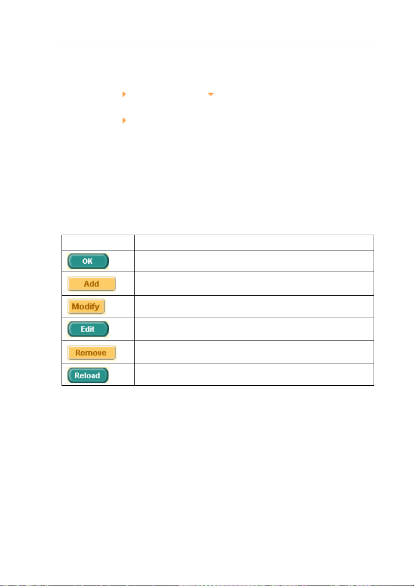
4.2.2 Commonly used buttons and icons
The following table describes the f unction fo r each butto n and icon u sed in the
application.
Table 6. Commonly used buttons and icons
Button/Icon Function
Stores any changes you have made on the current page.
Adds the existing configuration to the system, e.g. a static MAC
address or a firewall ACL rule and etc.
Modifies an existing entry
Modifies the existing configuration in the system, e.g. a static route
or a filter ACL rule and etc.
Deletes the selected item, e.g. a static route or a filter ACL rule and
etc.
Re-displays the current page with updated statistics or settings.
29
GigaX Series L2 Managed Switch User’s Guide
4.3 System Pages
System pages include management, IP setup, administration, reboot, and
firmware update function.
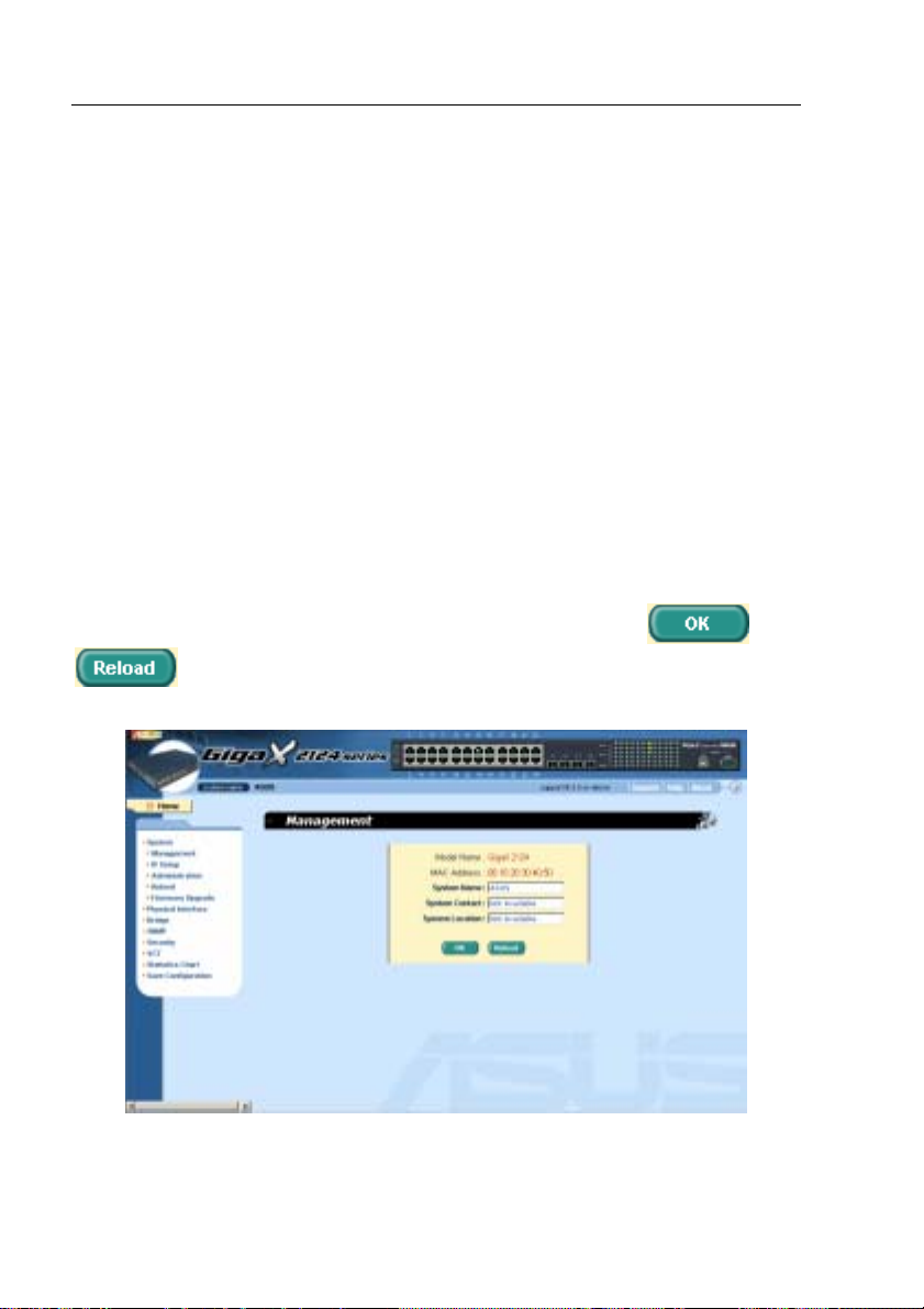
4.3.1 Management
The Management page contain s the foll owing i nformation:
Model Name: product name
MAC Address: switch MAC address
System Name: user assigned name to identify the system (editable)
System Contact (editable)
System Location (editable)
To save any changes and make it effective immediately, cli ck
to refresh the setting, as shown in Figure 12.
Figure 12. Management
30
. Use
 Loading...