


Asus X2024B User Manual

GigaX2024B
Layer 2 Managed Switch
User Manual

E2403
December 2005 V1
Copyright © 2005 ASUSTeK COMPUTER INC.
of this manual, including the products and software described in it, may be
reproduced, transmitted, transcribed, stored in a retrieval system, or translated
into any language in any form or by any means, except documentation kept by
the purchaser for backup purposes, without the express written permission of
ASUSTeK COMPUTER INC. (ASUS).
Product warranty or service will not be extended if: (1) the product is repaired,
modified or altered, unless such repair, modification of alteration is authorized in
writing by ASUS; or (2) the serial number of the product is defaced or missing.
ASUS provides this manual “as is” without warranty of any kind, either express
or implied, including but not limited to the implied warranties or conditions of
merchantability or fitness for a particular purpose. In no event shall ASUS,
its directors, officers, employees, or agents be liable for any indirect, special,
incidental, or consequential damages (including damages for loss of profits,
loss of business, loss of use or data, interruption of business and the like), even
if ASUS has been advised of the possibility of such damages arising from any
defect or error in this manual or product.
Specifications and information contained in this manual are furnished for
informational use only, and are subject to change at any time without notice,
and should not be construed as a commitment by ASUS. ASUS assumes no
responsibility or liability for any errors or inaccuracies that may appear in this
manual, including the products and software described in it.
Products and corporate names appearing in this manual may or may not be
registered trademarks or copyrights of their respective companies, and are used
only for identification or explanation and to the ownersʼ benefit, without intent to
infringe.
All Rights Reserved. No part

GigaX2024B L2 Managed Switch User Manual
Federal Communications Commission Statement
This device complies with Part 15 of the FCC Rules. Operation is subject to the
following two conditions:
• This device may not cause harmful interference, and
• This device must accept any interference received including interference
that may cause undesired operation.
This equipment has been tested and found to comply with the limits for a Class
B digital device, pursuant to Part 15 of the FCC Rules. These limits are designed
to provide reasonable protection against harmful interference in a residential
installation. This equipment generates, uses and can radiate radio frequency
energy and, if not installed and used in accordance with manufacturerʼs
instructions, may cause harmful interference to radio communications. However,
there is no guarantee that interference will not occur in a particular installation. If
this equipment does cause harmful interference to radio or television reception,
which can be determined by turning the equipment off and on, the user is
encouraged to try to correct the interference by one or more of the following
measures:
• Reorient or relocate the receiving antenna.
• Increase the separation between the equipment and receiver.
• Connect the equipment to an outlet on a circuit different from that to which
the receiver is connected.
• Consult the dealer or an experienced radio/TV technician for help.
WARNING!
graphics card is required to assure compliance with FCC regulations. Changes
or modifications to this unit not expressly approved by the party responsible for
compliance could void the userʼs authority to operate this equipment.
The use of shielded cables for connection of the monitor to the
Canadian Department of Communications Statement
This digital apparatus does not exceed the Class B limits for radio noise
emissions from digital apparatus set out in the Radio Interference Regulations of
the Canadian Department of Communications.
This class B digital apparatus complies with Canadian ICES-003.
i

GigaX2024B L2 Managed Switch User Manual
ASUS contact information
ASUSTeK COMPUTER INC. (Asia-Pacific)
Address: 150 Li-Te Road, Peitou, Taipei, Taiwan
General Tel: +886-2-2894-3447
General Fax: +886-2-2894-7798
Web Site: www.asus.com.tw
Technical Support
MB/Others (Tel): +886-2-2890-7121 (English)
Notebook (Tel): +886-2-2890-7122 (English)
Desktop/Server (Tel): +886-2-2890-7123 (English)
Support Fax: +886-2-2890-7698
ASUS COMPUTER INTERNATIONAL (America)
Address: 44370 Nobel Drive, Fremont, CA 94538, USA
General Fax: +1-502-933-8713
General Email: tmd1@asus.com
Web Site: usa.asus.com
Technical Support
Support Fax: +1-502-933-8713
General Support: +1-502-995-0883
Notebook Support: +1-510-739-3777 x5110
Support Email: tsd@asus.com
ASUS COMPUTER GmbH (Germany and Austria)
Address: Harkort Str. 25, D-40880 Ratingen, BRD, Germany
General Fax: +49-2102-9599-31
General Email: sales@asuscom.de (for marketing requests only)
Technical Support
Support Hotlines: (Components) +49-2102-95990
(Notebook PC) +49-2102-959910
Support Fax: +49-2102-959911
Support Email: www.asuscom.de/de/support (for online support)
Web Site: www.asuscom.de
ASUS COMPUTER (Middle East and North Africa)
Address: P.O. Box 64133, Dubai, U.A.E.
General Tel.: +9714-283-1774
General Fax: +9714-283-1775
General Email: www.ASUSarabia.com
ii

GigaX2024B L2 Managed Switch User Manual
Table of content
1 Introduction .......................................................................... 1
1.1 GigaX2024B features ............................................................... 1
1.2 Conventions used in this document ......................................... 2
1.2.1 Notations ..................................................................................... 2
1.2.2 Typography .................................................................................. 2
1.2.3 Symbols ....................................................................................... 2
2 Getting to know the GigaX2024B ....................................... 3
2.1 Package contents .................................................................... 3
2.2 Front panel ............................................................................... 4
2.3 Rear panel ................................................................................ 5
2.4 Technical specifications ............................................................ 5
3 Quick start guide .................................................................6
3.1 Part 1 — Installing the hardware .............................................. 6
3.1.1 Installing the switch on a flat surface .......................................... 6
3.1.2 Mounting the switch on a rack ..................................................... 6
3.2 Part 2 — Setting up the switch ................................................. 6
3.2.1 Connect the console port ............................................................. 6
3.2.2 Connect to the computers or a LAN ............................................ 7
3.2.3 Attach the RPS module .............................................................. 7
3.2.4 Attach the power adapter ............................................................ 7
3.3 Part 3 — Basic switch setting for management ....................... 8
3.3.1 Setting up through the console port ............................................ 8
3.3.2 Setting up through the Web interface ........................................ 10
4 Management with the Web Interface ................................12
4.1 Log into Web user interface ................................................... 12
4.2 Functional layout .................................................................... 13
4.2.1 Menu navigation tips .................................................................. 14
iii

GigaX2024B L2 Managed Switch User Manual
4.2.2 Commonly used buttons and icons ........................................... 14
4.3 System pages ........................................................................ 15
4.3.1 Management .............................................................................. 15
4.3.2 IP setup ..................................................................................... 15
4.3.3 Reboot ...................................................................................... 16
4.4 Physical interface ................................................................. 17
4.5.1 Spanning tree ............................................................................ 19
4.5.1.1 STP status ......................................................................... 19
4.5.1.2 Current roots ...................................................................... 20
4.5.1.3 Bridge parameters ............................................................. 21
4.5.1.4 Port parameters ................................................................. 22
4.5.1.5 Runtime status ................................................................... 23
4.5.2 Link aggregation static ............................................................... 23
4.5.3 LACP ......................................................................................... 25
4.5.4 Mirroring .................................................................................... 26
4.5.5 Static multicast .......................................................................... 27
4.5.6 IGMP snooping .......................................................................... 28
4.5.7 Traffic control ............................................................................. 29
4.5.8 Dynamic addresses ................................................................... 29
4.5.9 Static addresses ........................................................................ 30
4.5.10 VLAN configuration .................................................................. 31
4.5.11 GVRP ....................................................................................... 32
4.5.12 QoS and CoS .......................................................................... 33
4.5.12.1 802.1p priority .................................................................. 33
4.5.12.2 CoS queue mapping ........................................................ 34
4.5.12.3 QoS bandwidth ................................................................ 35
4.6 SNMP ..................................................................................... 36
4.6.1 Community table ........................................................................ 36
4.6.2 Host table .................................................................................. 37
iv

GigaX2024B L2 Managed Switch User Manual
4.6.3 Trap setting ................................................................................ 37
4.6.4 SNMPv3 VGU table ................................................................... 38
4.6.4.1 VACM view ........................................................................ 38
4.6.4.2 VACM group ...................................................................... 39
4.6.4.3 USM user ........................................................................... 40
4.7 Filter pages ............................................................................ 41
4.7.1 Filter set ..................................................................................... 41
4.7.2 Filter attach ................................................................................ 43
4.8 Security .................................................................................. 44
4.8.1 Port access control .................................................................... 44
4.8.2 Dial-in user ................................................................................ 46
4.8.3 RADIUS ..................................................................................... 47
4.8.4 Port security ............................................................................... 48
4.8.4.1 Port configuration .............................................................. 48
4.8.4.2 Port status ......................................................................... 49
4.8.4.3 Secure MAC address ........................................................ 50
4.9 Traffic chart ............................................................................ 51
4.9.1 Traffic comparison ..................................................................... 51
4.9.2 Error group chart ....................................................................... 52
4.10 Cable diagnosis ................................................................... 53
4.11 Save configuration ............................................................... 53
5 Console interface ..............................................................54
5.1 Power-on self test .................................................................. 54
5.1.1 Boot ROM command mode ....................................................... 54
5.1.2 Boot ROM commands ............................................................... 55
5.2 Login and logout ................................................................... 56
5.3 CLI commands ...................................................................... 56
5.3.1 User account ............................................................................ 56
5.3.1.1 Add user ............................................................................56
v

GigaX2024B L2 Managed Switch User Manual
5.3.1.2 Delete user ........................................................................56
5.3.2 Backup and Restore ................................................................. 56
5.3.2.1 Backup start-up configuration file ...................................... 56
5.3.2.2 Restore start-up configuration file ...................................... 57
5.3.3 System management configuration .......................................... 57
5.3.3.1 Firmware upgrade ............................................................. 57
5.3.3.2 configure terminal .............................................................. 57
5.3.3.3 enable ................................................................................ 57
5.3.3.4 disable ...............................................................................57
5.3.3.5 end ..................................................................................... 58
5.3.3.6 exit ..................................................................................... 58
5.3.3.7 help .................................................................................... 58
5.3.3.8 host name .......................................................................... 58
5.3.3.9 System contact .................................................................. 58
5.3.3.10 System Location .............................................................. 59
5.3.3.11 IP address and network mask .......................................... 59
5.3.3.12 Default gateway ............................................................... 59
5.3.3.13 reboot .............................................................................. 59
5.3.3.14 reload default-config file .................................................. 60
5.3.3.15 show running-config ........................................................ 60
5.3.3.16 write ................................................................................ 60
5.3.3.17 Assign a new user account .............................................. 60
5.3.3.18 Delete a new user account .............................................. 60
5.3.4 Physical interface commands .................................................... 60
5.3.4.1 Interface mode ................................................................... 61
5.3.4.2 Interface duplex ................................................................. 61
5.3.4.3 Interface flow control ......................................................... 61
5.3.4.4 Show L2 interface ............................................................. 61
5.3.5 IP interface ................................................................................ 62
vi

GigaX2024B L2 Managed Switch User Manual
5.3.5.1 show vlan name string ....................................................... 62
5.3.5.2 Create a vlan entry ............................................................62
5.3.5.3 interface vlan VLAN-ID ...................................................... 62
5.3.5.4 ip address .......................................................................... 62
5.3.5.5 ip dhcp client ...................................................................... 63
5.3.5.6 ip route ............................................................................... 63
5.3.6 Spanning Tree .......................................................................... 63
5.3.6.1 show spanning-tree summary ........................................... 63
5.3.6.2 spanning-tree enable and disable ..................................... 63
5.3.7 Link aggregation ....................................................................... 63
5.3.7.1 trunk aggregation group .................................................... 63
5.3.7.2 trunk load balancing .......................................................... 64
5.3.7.3 show aggregation-link trunk ............................................... 64
5.3.8 LACP ........................................................................................ 64
5.3.8.1 lacp aggregation-link trunk ................................................ 64
5.3.8.2 disable lacp aggregation-link trunk .................................... 64
5.3.8.3 lacp system-priority ............................................................ 64
5.3.9 Mirroring ................................................................................... 65
5.3.9.1 Mirror setting ...................................................................... 65
5.3.9.2 Show mirror ......................................................................65
5.3.9.3 No mirror ............................................................................ 65
5.3.9.4 No mirror ............................................................................ 65
5.3.10 Static Multicast ....................................................................... 65
5.3.10.1 mac-address-table multicast ............................................ 65
5.3.10.2 no mac-address-table multicast ....................................... 66
5.3.10.3 show mac-address-table multicast .................................. 66
5.3.11 IGMP snooping ....................................................................... 66
5.3.11.1 ip igmp snooping .............................................................. 66
5.3.11.2 interval time ...................................................................... 66
vii

GigaX2024B L2 Managed Switch User Manual
5.3.12 Traffic control .......................................................................... 66
5.3.12.1 storm-control .................................................................... 66
5.3.12.2 no storm-control ............................................................... 67
5.3.12.3 show storm-control ..........................................................67
5.3.13 Dynamic addresses ................................................................ 67
5.3.13.1 clear dynamic mac-address ............................................. 67
5.3.13.2 aging time ........................................................................ 67
5.3.13.3 no aging time ................................................................... 67
5.3.13.4 show mac-address-table aging-time ................................ 68
5.3.14 Static addresses ..................................................................... 68
5.3.14.1 add static mac-address ................................................... 68
5.3.14.2 show mac-address-table ................................................. 68
5.3.15 VLAN ...................................................................................... 68
5.3.15.1 show vlan name string ..................................................... 68
5.3.15.2 vlan vid ............................................................................ 68
5.3.15.3 name string ...................................................................... 69
5.3.15.4 access vlan ...................................................................... 69
5.3.15.5 allowed VLANs ................................................................69
5.3.16 GVRP ..................................................................................... 69
5.3.16.1 clear gvrp statistics .......................................................... 69
5.3.16.2 gvrp mode ........................................................................ 69
5.3.16.3 show gvrp configuration ................................................... 70
5.3.16.4 show gvrp statistics ......................................................... 70
5.3.17 CoS/QoS ................................................................................ 70
5.3.17.1 queue cos-map ................................................................ 70
5.3.17.2 show queue cos-map ...................................................... 70
5.3.17.3 qos mode ......................................................................... 70
5.3.17.4 show cos policy ............................................................... 70
5.3.17.5 qos ingress bandwidth ..................................................... 71
viii

GigaX2024B L2 Managed Switch User Manual
5.3.18 SNMP ..................................................................................... 71
5.3.18.1 show rmon statistics ........................................................71
5.3.18.2 show snmp-server community ......................................... 71
5.3.18.3 snmp-server host ............................................................. 71
5.3.19 Filter ........................................................................................ 71
5.3.19.1 deny any host ..................................................................71
5.3.19.2 filter set ............................................................................ 72
5.3.19.3 filter conditions ................................................................. 72
5.3.19.4 filter attach ....................................................................... 72
5.3.20 Port access control ................................................................. 72
5.3.20.1 dot1x guest-vlan ..............................................................72
5.3.20.2 dot1x max-req .................................................................. 73
5.3.20.3 dot1x port-control ............................................................. 73
5.3.21 Dial-in user ............................................................................. 73
5.3.21.1 dot1x username password .............................................. 73
5.3.21.2 show dot1x user .............................................................. 73
5.3.22 RADIUS .................................................................................. 74
5.3.22.1 RADIUS settings .............................................................. 74
5.3.22.2 show dot1x radius ............................................................ 74
5.3.23 Port security ............................................................................ 74
5.3.23.1 show port security ............................................................ 74
5.3.23.2 clear port security ............................................................74
5.3.23.3 switchport port-security .................................................... 75
5.3.23.4 switchport port-security aging .......................................... 75
5.4 Miscellaneous commands ...................................................... 75
6
IP Addresses, network masks, and subnets ................... 76
6.1 IP addresses .......................................................................... 76
6.1.1 Structure of an IP address ......................................................... 76
6.1.2 Network classes ........................................................................ 77
ix

GigaX2024B L2 Managed Switch User Manual
6.2 Subnet masks ........................................................................ 77
7 Troubleshooting ................................................................79
7.1 Diagnosing problems using IP utilities ................................... 79
7.1.1 ping ............................................................................................ 79
7.1.2 nslookup ........................................................................................ 80
7.2 Replacing defective fans ........................................................ 81
7.3 Simple fixes ............................................................................ 83
8 Glossary .............................................................................85
x

GigaX2024B L2 Managed Switch User Manual
1 Introduction
Congratulations on becoming the owner of the ASUS GigaX2024B Layer 2
managed switch! You may now manage your LAN (local area network) through
a friendly and powerful user interface.
This user manual tells how to set up the GigaX2024B switch, and how to
customize its configuration to get the most out of this product.
1.1 GigaX2024B features
• Total 24 x 10/100BSAE-T and 2 x 10/100/1000BASE-T auto-sensing gigabit
Ethernet switching ports
• Two small form factor (SFP) gigabit interface converter (GBIC) slots
• Automatic MDI/MDIX support for All ports
• Compliant with 802.3z and 802.3ab specifications
• 802.1D transparent bridge
• STP/RSTP/MSTP
• 16K MAC address cache with hardware-assisted aging
• 802.3x flow control
• 802.1Q-based tagged VLAN, up to 255 VLANs
• 802.1p class of service, 4 queues per port
• IGMP snooping
• 802.3ad link aggregation (trunking), up to 6 trunk groups
• LACP
• GVRP
• Access Control List
• Rate Limiting, Granularity to 1Mbps
• Port Mirroring
• 802.1x
• Port Security
• DHCP Snooping
• SNMP v1, v2, v3
• MIB-II
1

GigaX2024B L2 Managed Switch User Manual
• Enterprise MIB for PSU, fan, and system temperature, voltage
• Telnet/SSH remote login
• TFTP for firmware update and configuration backup
• Cisco Like CLI
• Web GUI
• LEDs for port link status
• LEDs system, redundant power supply (RPS), and fan status
1.2 Conventions used in this document
1.2.1 Notations
• Acronyms are defined the first time they appear in text and in the glossary.
• For brevity, the GigaX2024B switch is referred to as “the switch.”
• The terms LAN and network are used interchangeably to refer to a group of
Ethernet-connected computers at one site.
1.2.2 Typography
Boldface
lists, and text strings you type when prompted by the program.
type text is used for items you select from menus and drop-down
1.2.3 Symbols
This document uses the following icons to call your attention to specific
instructions or explanations.
Provides clarification or additional information on the current
topic.
Explains terms or acronyms that may be unfamiliar to many
readers. These terms are also included in the Glossary.
Provides messages of high importance, including messages
relating to personal safety or system integrity.
2

GigaX2024B L2 Managed Switch User Manual
2 Getting to know the GigaX2024B
2.1 Package contents
The GigaX2024B switch package comes with the following items:
• GigaX 2024B L2 managed switch
• AC power cord
• Null modem cable for console interface (DB9)
• Rack installation kit (two brackets with six #6-32 screws)
• USB cable for console interface
• Installation CD-ROM
• Quick installation guide
Figure 1. GigaX L2 managed switch package contents
3
GigaX2024B L2 Managed Switch User Manual
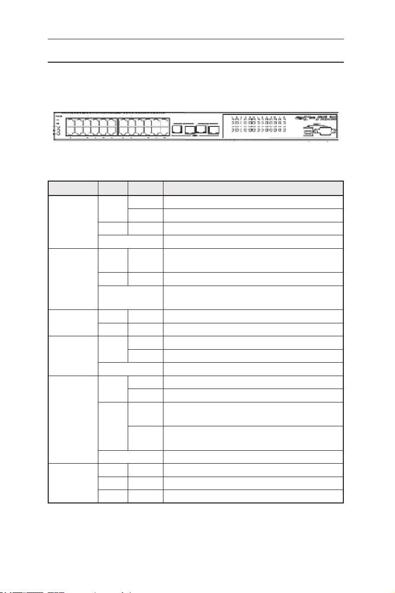
2.2 Front panel
The front panel includes 24 RJ-45 10/100Base-T ports, two 10/100/1000Base-T
ports, two SPF GBIC port and LED indicators that show the status of the system,
RPS, fan, and ports.
Figure 2. Front panel
Table 1. Front panel labels and LEDs
Label Color Status Description
SYSTEM Green ON Unit is powered on
Flashing Self-test, initiating, or downloading
Amber ON Abnormal temperature or voltage
OFF No power
RPS Green ON The Power Supply Unit (PSU) is working properly
and the switch has a good redundant power supply
Amber ON The PSU is abnormal and the switch is powered by RPS
OFF No power (system LED is also off); RPS does not work
properly or not installed (system LED is on)
FAN Green ON Both fans are working properly
Amber ON Both or either one of the fans stopped
10/100 ports Green ON Ethernet link is established
Flashing Data is being transmitted/received
OFF No Ethernet link
10/100/1000
port status
10/100/1000
port speed
Green ON Link (RJ-45 or SFP) is present; port is enabled
Flashing Data is being transmitted/received
Amber ON Link is present, but port is disabled either manually or
by spanning tree
Flashing Port is in one of the STP blocking, listening and
learning state
OFF No Ethernet link
Green ON 1000Mbps
Amber ON 100Mbps
OFF 10Mbps
4
GigaX2024B L2 Managed Switch User Manual
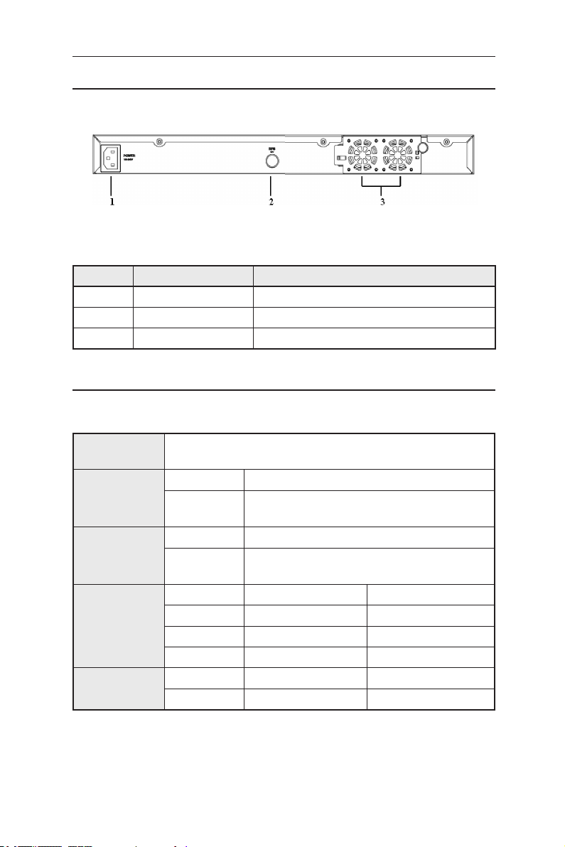
2.3 Rear panel
The switch rear panel contains the fan modules, a power connector and one RPS port.
Figure 3. Rear panel
Table 2. Rear panel labels
No. Item Description
1 Power Connector Connects to the supplied power cord
2 FAN1-FAN2 Replaceable system fans
3 RPS Redundant Power Supply connector
2.4 Technical specifications
Table 3. Technical specifications
Physical
Dimensions
Power
Redundant
Power Supply
(RPS)
Environmental
Ranges
Replaceable
Fans
43.5mm(H) x 444 mm(W) x 322mm(D)
Input Consumption
100-240V AC/
2.5A 50-60Hz
Input Output
100-240V AC/
1.8A 50-60Hz
Temperature 0 to 40°C (32 to 122°F) -25 to 70°C (-40 to 158°F)
Humidity 15 to 90% 0 to 95%
Altitude up to 10,000ft (3,000m) up to 40,000 ft (12,000m)
Dimensions Voltage and Current Speed
40 x 40 x 20 mm 12VDC, 0.13A 8200RPM
< 50 watts
12V DC/12.5A
Operating Storage
5

GigaX2024B L2 Managed Switch User Manual
3 Quick start guide
This section provides the basic instructions to set up the switch environment.
Refer also to the GigaX2024B Installation Guide.
Part 1 shows how to install the GigaX2024B on a flat surface or on a rack.
Part 2 provides instructions to set up the hardware.
Part 3 shows how to configure basic settings on the GigaX2024B switch.
Before start, obtain the following information from your network administrator:
IP address for the switch
Default gateway for the network
Network mask for this network
3.1 Part 1 — Installing the hardware
3.1.1 Installing the switch on a flat surface
The switch must be installed on a level surface that can support the weight of
the switch and its accessories. Attach four rubber pads on the marked location
on the bottom of the switch.
3.1.2 Mounting the switch on a rack
1. Position the bracket posts with the holes on both sides of the switch.
2. Use three screws to secure the bracket to the switch.
3. Repeat the above steps for the other side of the switch.
4. Use four rack-mount screws to mount the switch to the rack (The rack-mount
screws are not provided in the package).
3.2 Part 2 — Setting up the switch
3.2.1 Connect the console port
For console management, use an RS232 (DB9) or a USB cable (requiring
installation of the USB driver included in the support CD) to connect the switch.
If you want to use Web interface, connect your PC to the switch using an
Ethernet cable.
6
GigaX2024B L2 Managed Switch User Manual
3.2.2 Connect to the computers or a LAN
You can use Ethernet cable to connect computers, hubs and other switches to
the switch ports. Either crossover or straight-through Ethernet cable can apply
for connecting these devices.
Use a twisted-pair Category 5 Ethernet cable to connect the
1000BASE-T port. Otherwise, the link speed can not reach
1Gbps.
3.2.3 Attach the RPS module
Connect your Redundant Power Supply (RPS) module (optional) to the RPS jack on
the rear panel of the switch and make sure the other end of the RPS is connected to
the power cord. Connect to the power cord to a grounded power outlet.
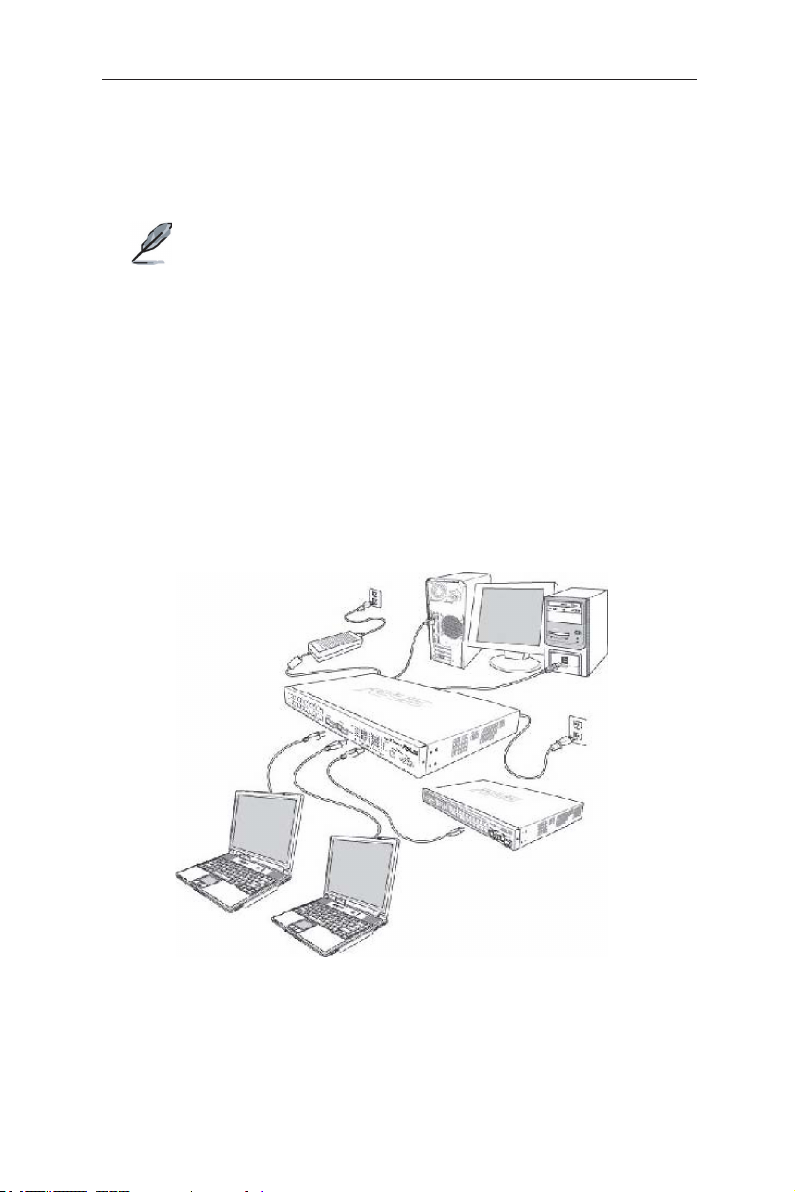
3.2.4 Attach the power adapter
1. Connect the AC power cord to the POWER receptacle on the back of the switch
and plug the other end of the power cord into a wall outlet or a power strip.
2. Check the front LED indicators with the description in Table 4. If the LEDs
light up as described, the switch hardware is working properly.
Figure 4. Overview of Hardware Connections
7

GigaX2024B L2 Managed Switch User Manual
Table 4. LED Indicators
No. LED Description
1 System Solid green indicates that the switch is turned on. If this
light is off, check if the power adapter if attached to the
switch and plugged into a power source.
2 Switch ports
[1] to [26]
3 RPS Solid green indicates that an RPS module is successfully
4 Fan Solid green indicates that all fans are working properly
Solid green indicates that the connection between the
switch and other devices is built. Flashing means the
switch is transmitting data .
installed.
3.3 Part 3 — Basic switch setting for management
After completing the hardware connections, configure the basic settings for your
switch. You can manage the switch using the following methods:
•
Web interface:
management via Java®-enabled IE5.0 or higher version.
•
Command Line Interface:
3.3.1 Setting up through the console port
1. Use the supplied crossover RS-232 cable to connect to the console port on
the back of the switch. This port is a male DB-9 connector, implemented as a
data terminal equipment (DTE) connection. Tighten the retaining screws on
the cable to secure it on the connector. Connect the other end of the cable to
a PC running terminal emulation software. e.g Hyper Terminal.
2. Use the supplied USB cable to connect to a PC. You have to install the USB
driver from the switch CD-ROM before connection. The USB driver simulates
an additional COM port under Windows Me/2K/XP OS.
3. Make sure the settings of your terminal emulation software as follows:
a) Choose the appropriate serial port number
b) Set the data baud rate to 9600
c) Set the data format to no parity, 8 data bits and 1 stop bit
d) No flow control
e) Set VT1000 for emulation mode
4. After setting up the terminal, you can see the prompt “(ASUS)%” on the
terminal.
the switch features a set of web pages which enable easy
using console port to configure the switch.
8

5. Type “login” to access the command line interface. The default user name is
“admin”. Skip the password by pressing
GigaX2024B L2 Managed Switch User Manual
<Enter>
.
You can change the password at any time through CLI (see
section 5.3.1). To protect your switch from unauthorized access,
you must change the default password as soon as possible.
6. Follow these steps to assign an IP address to the switch:
Follow these steps to assign an IP address to the switch:
a) Type “enable”.
b) Type “configure terminal”, new prompt is “ASUS(config)#”.
c) Type “interface vlan 1”, the prompt is “ASUS (config-if)#”.
d) Type “ip address <your ip address> <your network mask>”. For example, if
your switch IP is 192.168.1.1 and the network mask is 255.255.255.0. Then
you should type “ip address 192.168.1.1/24”.
e) Type “end”, it will return to previous level with prompt “ASUS#”.
f) Type “write”, the changes will be applied and written to configuration file.
g) Type “reboot”.
If the switch has to be managed across networks, then a default gateway
or a static route entry is required. Follow these steps to assign a default
gateway or static route entry to the switch:
a) Entering “ASUS#”.
b) Type “ show run ning -con figu rati on” to vie w cur rent con figu rati on. If
incorrect route entry has been set, you should type “no ip route 0.0.0.0/0
192.168.1.254” to remove it.
c) Type “configure terminal”, new prompt is “ASUS(config)#”.
d) Type “no ip route 0.0.0.0/0 192.168.1.254” to clear default route.
e) Type “ip route 0.0.0.0/0 192.168.1.2” to set your default route.
f) Type “end”
g) Type “write”.
9
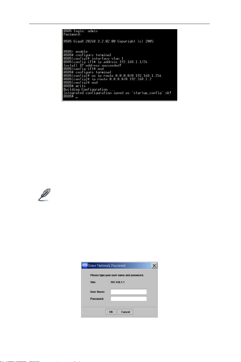
GigaX2024B L2 Managed Switch User Manual
Figure 5. Console setup
3.3.2 Setting up through the Web interface
To connect your PC to the switch, your PC must have a valid IP in your network.
Contact your network administrator to obtain a valid IP for the switch. If you wish
to change the default IP address of the switch, follow section 3.3.1 to change the
IP address.
1. If Java Runtime Environment is not installed on your PC, Your PC will
automatically download and installs it. It means that your PC should be able
to reach the web site. If the Internet is not available, you should prepare it on
diskette and install it.
Java Runtime Environment is necessary to install on you PC
to access Web configuration manager. You can install it from
support CD packed with the main device.
2. At any PC connected to the network that the switch can access, open your
Web browser (Internet Explorer), and type the following URL in the address/
location box, and press
This is the factory default IP address of the switch.
A login screen appears, as shown in Figure 6.
<Enter>
:
http://192.168.1.1
10
Figure 6. Login
Enter your user name and password, and then click OK to enter the configuration
Manager. Use the following defaults the first time you log into this interface:
Default User Name: admin
Default Password: (no password)
GigaX2024B L2 Managed Switch User Manual
You can change the password at any time (see section 6.3.1
System Commands.
The browser will download java applet from the switch and this
will take several seconds.
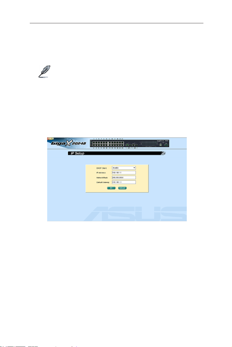
3. To setup a new IP address, click
address, network mask and default gateway, then click OK.
4. When the new address is applied to the switch, the browser can no longer
update the switch status window or retrieve any page. You need to retype
the new IP address in the address/location box, and press
Web link returns.
System
, then
IP Setup
<Enter>
. Fill in the IP
, then the
Figure 7. IP setup
11

GigaX2024B L2 Managed Switch User Manual
4 Management with the Web Interface
The switch provides Web pages that allow switch management through the
Internet. The program is designed to work best with Microsoft Internet Explorer®
6.0, or later versions with Java® enabled.
4.1 Log into Web user interface
1. Open the web browser (IE) on your computer, type the following in the web
address (or location) box, and press
http://192.168.1.1
This is the factory default IP address for the switch. A login screen displays as
shown in Figure 8.
Figure 8. Configuration manager login screen
2. Enter your user name and password, then click OK.
Use the following defaults the first time you log into the system. You can
change the password at any time through CLI interface (see section 6.3.1 on
page 57).
Default User Name: admin
Default Password: <no password>
The home page appears each time you log into the program. See Figures 11
and 12).
<Enter>
:
12
GigaX2024B L2 Managed Switch User Manual
Figure 9. Home page
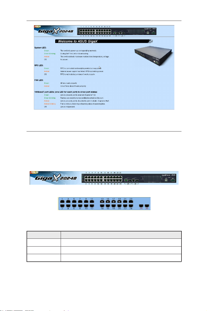
4.2 Functional layout
The web-based configuration page consists of three separate frames. The top
frame has a switch logo and front panel as shown in Figures 13 and 14. This
frame remains on the top of the browser window all the times and updates the
LED status periodically. See Table 4 for the LED definitions. See Table 5 for the
color status description.
Figure 10. Top frame
Figure 11. Port selection panel
Table 5. Port color description
Port Color Description
Green Ethernet link is established
Amber Link is present but port is disabled manually or by spanning tree
OFF
Clicking on the port icon of the switch displays the port configuration in the lower
right frame.
No Ethernet link
13
GigaX2024B L2 Managed Switch User Manual
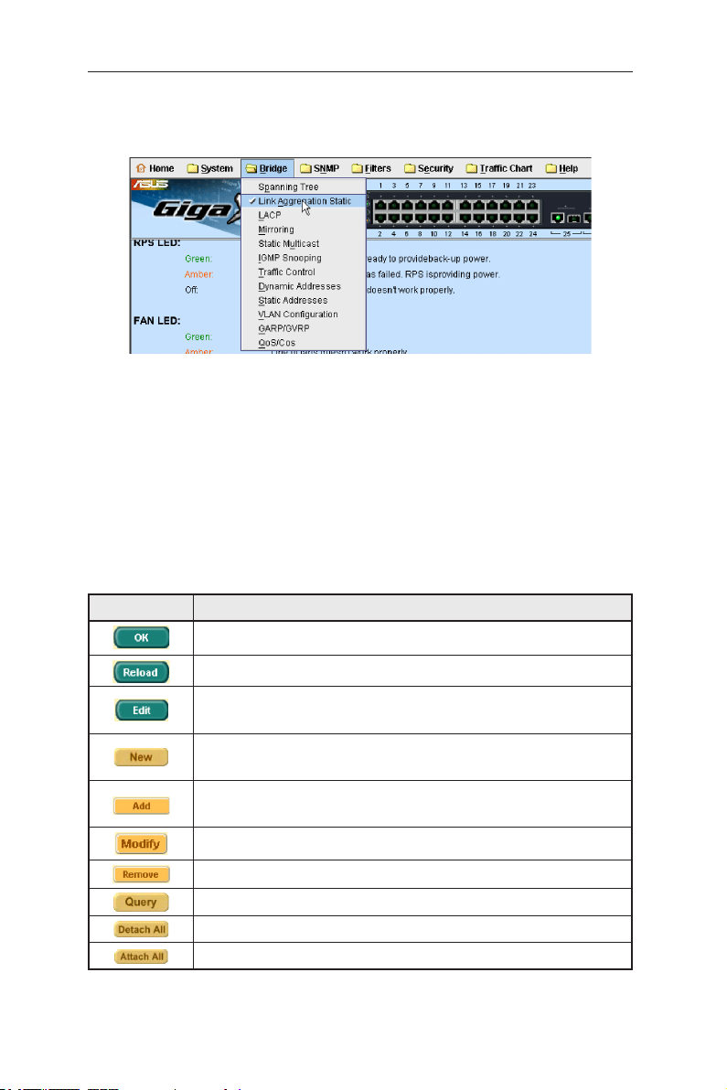
The menu items, as shown in Figure 12, contains all the features available for
switch configuration. These features are grouped into categories, e.g. System,
Bridge. You can click on any of these to display a specific configuration page.
Figure 12. Menu items
4.2.1 Menu navigation tips
To open a specifc configuration page, click on the desired menu item.
4.2.2 Commonly used buttons and icons
The following table describes the function for each button and icon used in the
application.
Table 6. Commonly used buttons and icons
Button/Icon Description
14
Stores any changes you have made on the current page.
Re-displays the current page with updated statistics or settings.
Modifies the existing configuration in the system, e.g. a static route or
a filter ACL rule and etc.
Adds the existing configuration to the system, e.g. a static MAC address
or a firewall ACL rule and etc.
Adds the existing configuration to the system, e.g. a static MAC address
or a firewall ACL rule and etc.
Modifies an existing entry
Deletes the selected item, e.g. a static route or a filter ACL rule and etc.
Find status of a certain item
Detach the feature from all ports on selcetion panel
Attach the feature from all ports on selcetion panel
GigaX2024B L2 Managed Switch User Manual
4.3 System pages
System pages include management, IP setup, administration, reboot, and
firmware update function.
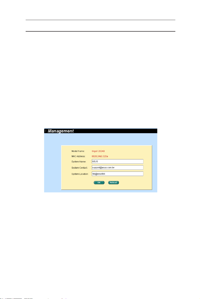
4.3.1 Management
The Management page contains the following information:
Model Name:
MAC Address:
System Name:
System Contact
System Location
Click on OK to make the setting effective immediately. Click on
refresh the setting to current value, as shown in Figure 13.
product name
switch MAC address
user assigned name to identify the system (editable).
(editable).
(editable).
Reload
to
Figure 13. Management
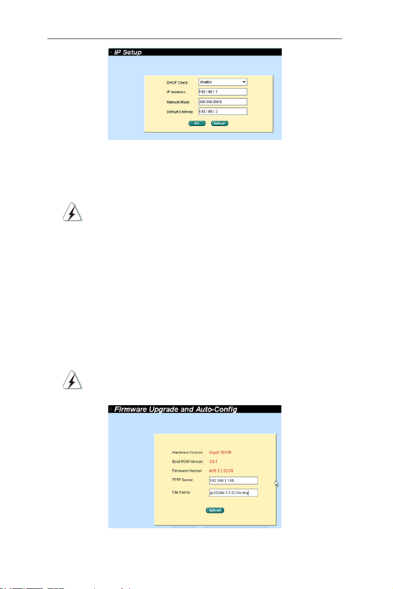
4.3.2 IP setup
The IP Setup page contains the following editable information:
DHCP Client:
IP Address:
Network Mask
Default Gateway
To save the changes and make them effective immediately, click OK. Use
to refresh the settings to current value.
Reload
Enables or disables DHCP.
Assigns a static IP address to the switch.
15
GigaX2024B L2 Managed Switch User Manual
Figure 14. IP Setup
4.3.3 Reboot
The Reboot page contains a
Rebooting the system stops the network traffic and terminates
the Web interface connection.
button. Clicking the button to reboot the system.
Reboot
4.3.5 Firmware upgrade
The Firmware Upgrade and Auto-config page contains the following information:
Hardware Version:
Boot ROM Version:
Firmware Version:
number renews automatically after firmware update is complete.
Enter the TFTP server IP address and firmware name. Click
the switch firmware. See Figure 15 for reference.
For example: TFTP Server: 192.168.1.155 File name: gx2024b-3.2.02.0a.img
Click the upload button to load the assigned firmware to the
switch. Reboot the switch when upgrade completes. You need to
login again to the web interface.
shows the hardware revision number.
shows the version of the boot code
shows the current running firmware version. This
Upgrade
to update
Figure 15. Firmware Upgrade
16
GigaX2024B L2 Managed Switch User Manual
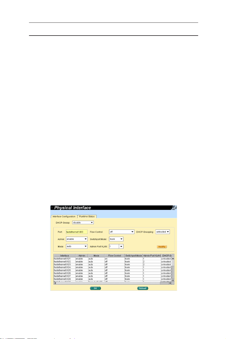
4.4 Physical interface
The Physical Interface shows the realtime Ethernet port status. You can configure
the port in following fields:
selects the port to configure
Port:
enables/disables the port
Admin:
set sthe speed and duplex mode
Mode:
Flow Control:
Switchport Mode:
Admin port VLAN:
DHCP-Snoop:
DHCP-Snooping:
Select the corresponding port number and configure the port setting, then
click on the
display window. However, the new settings do not take effect until the “Save
Configuration” is executed.
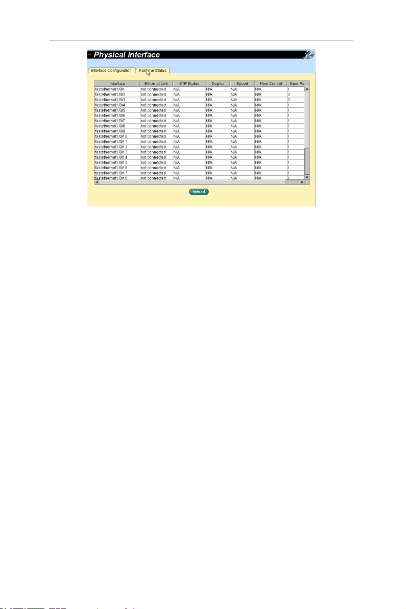
Runtime Status Window:
Ethernet Link:
STP Status:
Duplex:
Speed:
Flow Control:
mechanism.
enables/disables 802.3x flow control mechanism
sets port to trunk mode or access mode
assign the selected port to specific PVID
enable/disable DHCP snooping function
assign the selected port to be untrusted or trusted port
button. The field you change will update the content of the
Modify
displays the following information for each port
the link is connected or not connected.
the STP status
the duplex mode
link speed
the setting value to enable or disable 802.3x flow control
Figure 16. Physical interface - configuration
17
GigaX2024B L2 Managed Switch User Manual
Figure 17. Physical interface - runtime status
18
 Loading...