


ASUS V4-M3N8200 User Manual
V4-M3N8200
ASUS PC (Desktop Barebone)
Installation Manual

E4205
First Edition
October 2008
Copyright © 2008 ASUSTeK Computer Inc. All Rights Reserved.
No part of this manual, including the products and software described in it, may be reproduced,
transmitted, transcribed, stored in a retrieval system, or translated into any language in any form or by any
means, except documentation kept by the purchaser for backup purposes, without the express written
permission of ASUSTeK Computer Inc. (“ASUS”).
Product warranty or service will not be extended if: (1) the product is repaired, modied or altered, unless
such repair, modication of alteration is authorized in writing by ASUS; or (2) the serial number of the
product is defaced or missing.
ASUS PROVIDES THIS MANUAL “AS IS” WITHOUT WARRANTY OF ANY KIND, EITHER EXPRESS
OR IMPLIED, INCLUDING BUT NOT LIMITED TO THE IMPLIED WARRANTIES OR CONDITIONS OF
MERCHANTABILITY OR FITNESS FOR A PARTICULAR PURPOSE. IN NO EVENT SHALL ASUS, ITS
DIRECTORS, OFFICERS, EMPLOYEES OR AGENTS BE LIABLE FOR ANY INDIRECT, SPECIAL,
INCIDENTAL, OR CONSEQUENTIAL DAMAGES (INCLUDING DAMAGES FOR LOSS OF PROFITS,
LOSS OF BUSINESS, LOSS OF USE OR DATA, INTERRUPTION OF BUSINESS AND THE LIKE),
EVEN IF ASUS HAS BEEN ADVISED OF THE POSSIBILITY OF SUCH DAMAGES ARISING FROM ANY
DEFECT OR ERROR IN THIS MANUAL OR PRODUCT.
SPECIFICATIONS AND INFORMATION CONTAINED IN THIS MANUAL ARE FURNISHED FOR
INFORMATIONAL USE ONLY, AND ARE SUBJECT TO CHANGE AT ANY TIME WITHOUT NOTICE,
AND SHOULD NOT BE CONSTRUED AS A COMMITMENT BY ASUS. ASUS ASSUMES NO
RESPONSIBILITY OR LIABILITY FOR ANY ERRORS OR INACCURACIES THAT MAY APPEAR IN THIS
MANUAL, INCLUDING THE PRODUCTS AND SOFTWARE DESCRIBED IN IT.
Products and corporate names appearing in this manual may or may not be registered trademarks or
copyrights of their respective companies, and are used only for identication or explanation and to the
owners’ benet, without intent to infringe.
ii

Table of contents
Notices ......................................................................................................... vi
Safety information ..................................................................................... vii
About this guide ....................................................................................... viii
System package contents ........................................................................... x
Chapter 1: System introduction
1.1 Welcome! ...................................................................................... 1-2
1.2 Front panel ....................................................................................
1.3 Rear panel .....................................................................................
Voltage selector .............................................................................. 1-7
1.4 Internal components ....................................................................
Chapter 2: Basic installation
2.1 Preparation ................................................................................... 2-2
2.2 Before you proceed .....................................................................
2.3 Removing the side cover and front panel assembly ................
2.4 Central Processing Unit (CPU) ...................................................
2.4.1 Installing the CPU ...........................................................
2.4.2 Installing the heatsink and fan ........................................
2.5 Installing a DIMM ..........................................................................
2.5.1 Memory congurations ....................................................
2.5.2 Installing a DDR2 DIMM ...............................................
2.5.3 Removing a DDR2 DIMM .............................................
2.6 Expansion slots ..........................................................................
2.6.1 Installing an expansion card .........................................
2.6.2 Conguring an expansion card .....................................
2.6.3 PCI slots ........................................................................
2.6.4 PCI Express x1 slot .......................................................
2.6.5 PCI Express x16 slot .....................................................
2.7 Installing storage drives ............................................................
2.7.1 Installing an optical drive ...............................................
2.7.2 Installing a oppy disk drive ..........................................
2.7.3 Installing a hard disk drive ............................................
2.8 Reinstalling the front panel assembly and side cover ...........
2.9 Re-connecting cables ................................................................
1-2
1-4
1-8
2-2
2-3
2-4
2-4
2-6
2-8
2-8
2-12
2-12
2-13
2-13
2-13
2-15
2-15
2-15
2-16
2-16
2-16
2-17
2-18
2-19
iii

Table of contents
LED cables ................................................................................... 2-19
2.10 Reinstalling the cover ................................................................
Chapter 3: Starting up
3.1 Installing an operating system ................................................... 3-2
3.2 Powering up ..................................................................................
3.3 Support DVD information ............................................................
3.3.1 Running the support DVD ...............................................
3.3.2 Drivers menu ...................................................................
3.3.3 Utilities menu ..................................................................
3.3.4 Make Disk menu .............................................................
3.3.5 Manual menu ..................................................................
3.3.6 ASUS Contact information ..............................................
Chapter 4: Motherboard introduction
4.1 Introduction .................................................................................. 4-2
4.2 Motherboard layout ......................................................................
4.3 Jumpers ........................................................................................
4.4 Connectors ...................................................................................
Chapter 5: BIOS setup
5.1 Managing and updating your BIOS ............................................ 5-2
2.1.1 Creating a bootable oppy disk .......................................
5.1.2 ASUS EZ Flash 2 utility ...................................................
5.1.3 AFUDOS utility ................................................................
5.1.4 ASUS CrashFree BIOS 3 utility ......................................
5.1.5 ASUS Update utility ........................................................
5.2 BIOS setup program ..................................................................
5.2.1 BIOS menu screen ........................................................
5.2.2 Menu bar .......................................................................
5.2.3 Navigation keys .............................................................
5.2.4 Menu items ...................................................................
5.2.5 Sub-menu items ............................................................
5.2.6 Conguration elds .......................................................
5.2.7 Pop-up window .............................................................
5.2.8 Scroll bar .......................................................................
5.2.9 General help .................................................................
2-20
3-2
3-3
3-3
3-4
3-5
3-7
3-8
3-9
4-2
4-3
4-4
5-2
5-4
5-5
5-7
5-9
5-12
5-13
5-13
5-14
5-14
5-14
5-14
5-14
5-14
5-14
iv

Table of contents
5.3 Main menu .................................................................................. 5-15
5.3.1 System Time .................................................................
5.3.2 System Date .................................................................
5.3.3 Legacy Diskette A .........................................................
5.3.4 Primary IDE Master/Slave, SATA1~3, ESATA ...............
5.3.5 Storage Conguration ...................................................
5.3.6 System Information .......................................................
5.4 Advanced menu .........................................................................
5.4.1 JumperFree Conguration ............................................
5.4.2 CPU Conguration ........................................................
5.4.3 Chipset ..........................................................................
5.4.4 Onboard Devices Conguration ....................................
5.4.5 PCI PnP ........................................................................
5.4.6 USB Conguration ........................................................
5.4.7 Trusted Computing ........................................................
5.5 Power menu ................................................................................
5.5.1 Suspend Mode ..............................................................
5.5.2 ACPI
5.5.3 ACPI APIC Support ......................................................
5.5.4 APM Conguration ........................................................
5.5.5 Hardware Monitor .........................................................
5.6 Boot menu ..................................................................................
5.6.1 Boot Device Priority ......................................................
5.6.2 Boot Settings Conguration ..........................................
5.6.3 Security .........................................................................
5.7 Tools menu .................................................................................
5.7.1 ASUS EZ Flash 2 ..........................................................
5.7.2 AI NET 2
5.8 Exit menu ....................................................................................
2.0 Support ........................................................ 5-34
........................................................................ 5-42
5-15
5-15
5-15
5-16
5-18
5-19
5-20
5-20
5-22
5-23
5-30
5-31
5-32
5-33
5-34
5-34
5-34
5-35
5-36
5-37
5-37
5-38
5-39
5-41
5-41
5-43
v

Notices
Federal Communications Commission Statement
This device complies with Part 15 of the FCC Rules. Operation is subject to the
following two conditions:
•
This device may not cause harmful interference, and
•
This device must accept any interference received including interference that
may cause undesired operation.
This equipment has been tested and found to comply with the limits for a
Class B digital device, pursuant to Part 15 of the FCC Rules. These limits are
designed to provide reasonable protection against harmful interference in a
residential installation. This equipment generates, uses and can radiate radio
frequency energy and, if not installed and used in accordance with manufacturer’s
instructions, may cause harmful interference to radio communications. However,
there is no guarantee that interference will not occur in a particular installation. If
this equipment does cause harmful interference to radio or television reception,
which can be determined by turning the equipment off and on, the user is
encouraged to try to correct the interference by one or more of the following
measures:
•
Reorient or relocate the receiving antenna.
•
Increase the separation between the equipment and receiver.
•
Connect the equipment to an outlet on a circuit different from that to which the
receiver is connected.
•
Consult the dealer or an experienced radio/TV technician for help.
WARNING! The use of shielded cables for connection of the monitor to the
graphics card is required to assure compliance with FCC regulations. Changes
or modications to this unit not expressly approved by the party responsible for
compliance could void the user’s authority to operate this equipment.
Canadian Department of Communications Statement
This digital apparatus does not exceed the Class B limits for radio noise emissions
from digital apparatus set out in the Radio Interference Regulations of the
Canadian Department of Communications.
This class B digital apparatus complies with Canadian ICES-003.
vi

Safety information
Electrical safety
•
To prevent electrical shock hazard, disconnect the power cable from the
electrical outlet before relocating the system.
•
When adding or removing devices to or from the system, ensure that the power
cables for the devices are unplugged before the signal cables are connected.
•
If the power supply is broken, do not try to x it by yourself. Contact a qualied
service technician or your retailer.
Operation safety
•
Before installing devices into the system, carefully read all the documentation
that came with the package.
•
Before using the product, make sure all cables are correctly connected and the
power cables are not damaged. If you detect any damage, contact your dealer
immediately.
•
To avoid short circuits, keep paper clips, screws, and staples away from
connectors, slots, sockets and circuitry.
•
Avoid dust, humidity, and temperature extremes. Do not place the product in
any area where it may become wet. Place the product on a stable surface.
•
If you encounter technical problems with the product, contact a qualied
service technician or your retailer.
Lithium-Ion Battery Warning
CAUTION: Danger of explosion if battery is incorrectly replaced. Replace
only with the same or equivalent type recommended by the manufacturer.
Dispose of used batteries according to the manufacturer’s instructions.
VORSICHT: Explosionsgetahr bei unsachgemäßen Austausch der Batterie.
Ersatz nur durch denselben oder einem vom Hersteller empfohlenem
ähnljchen Typ. Entsorgung gebrauchter Batterien nach Angaben des
Herstellers.
LASER PRODUCT WARNING
CLASS 1 LASER PRODUCT
The symbol of the crossed out wheeled bin indicates that the product (electrical,
electronic equipment, Mercury-containing button cell battery) should not be
placed in municipal waste. Check local regulations for disposal of electronic
products.
vii

About this guide
Audience
This guide provides general information and installation instructions about
the ASUS Vintage V4-M3N8200 barebone system. This guide is intended
for experienced users and integrators with hardware knowledge of personal
computers.
How this guide is organized
This guide contains the following parts:
1. Chapter 1: System introduction
This chapter gives a general description of the ASUS
V4-M3N8200. The chapter lists the system features, including introduction on
the front and rear panel, and internal components.
2. Chapter 2: Basic installation
This chapter provides step-by-step instructions on how to install components
in the system.
3. Chapter 3: Starting up
This chapter helps you power up the system and install drivers and utilities
from the support CD.
4. Chapter 4: Motherboard information
This chapter gives information about the motherboard that comes with the
system. This chapter includes the motherboard layout, jumper settings, and
connector locations.
5. Chapter 5: BIOS setup
This chapter tells how to change system settings through the BIOS Setup
menus and describes the BIOS parameters.
viii

Conventions used in this guide
WARNING: Information to prevent injury to yourself when trying to
complete a task.
CAUTION: Information to prevent damage to the components when
trying to complete a task.
IMPORTANT: Instructions that you MUST follow to complete a task.
NOTE: Tips and additional information to aid in completing a task.
Where to nd more information
Refer to the following sources for additional information and for product and
software updates.
1. ASUS Websites
The ASUS websites worldwide provide updated information on ASUS
hardware and software products. Refer to the ASUS contact information.
2. Optional Documentation
Your product package may include optional documentation, such as warranty
yers, that may have been added by your dealer. These documents are not
part of the standard package.
ix
System package contents
Check your V4-M3N8200 system package for the following items.
If any of the items is damaged or missing, contact your retailer immediately.
Item description
1. ASUS V4-M3N8200 barebone system with
• ASUS motherboard
• Power supply unit
• ASUS chassis
2. Cable
• AC power cable
3. Support CD
4. User guide
x
Chapter 1
This chapter gives a general
description of the ASUS
V4-M3N8200. The chapter lists the
system features including introduction
on the front and rear panel, and
internal components.
System introduction
1.1 Welcome!
Thank you for choosing the ASUS V4-M3N8200!
The ASUS V4-M3N8200 is an all-in-one barebone system with a versatile home
entertainment feature.
The system comes in a stylish casing and powered by the ASUS motherboard with
the AMD Socket AM2+ that supports the AMD® Phenom™FX / Phenom™ / Athlon™ /
TM
Sempron
The system supports up to 8 GB of system memory using DDR2-1066/800/
667/533 DIMMs. High-resolution graphics via Nvidia on board Gfx or PCI Express
x16 slot, Serial ATA, USB 2.0, and 8-channel audio feature the system and take
you ahead in the world of power computing.
processors.
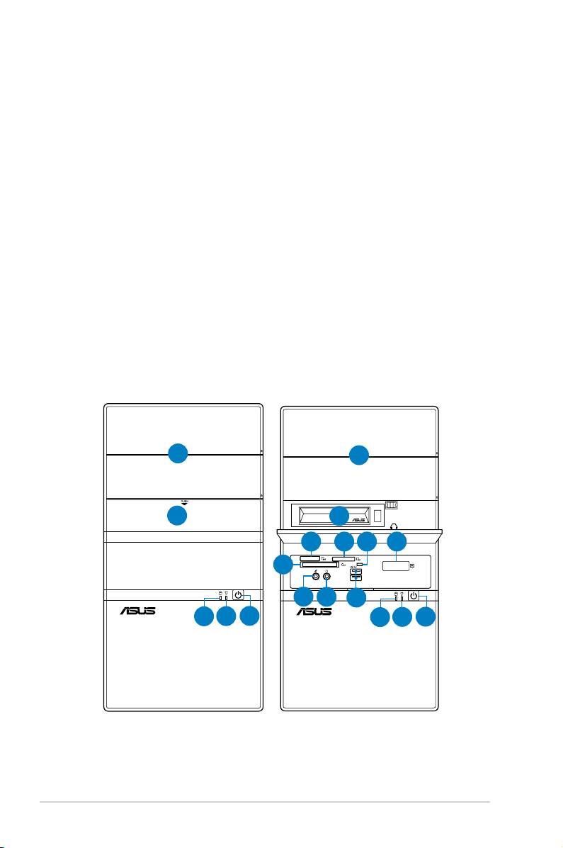
1.2 Front panel
The front panel includes the optical drive bays, hard disk drive bay, power button,
and I/O ports.
1
2
4
1
3
7
6
5
8
9
10
11
14
13
12
1-2 Chapter 1: System introduction
12
13
14

1. 5.25-inch drive bay cover
2. 3.5-inch drive bay cover
3. 2.5-inch portable hard disk drive*
®
4. MemoryStick
/Memory Stick Pro™ card slot
5. Secure Digital™/Multimedia Card slot
6. Card reader LED
7. Infrared window*
®
8. CompactFlash
/Microdrive™ card slot
9. Microphone port
10. Headphone port
11. USB 2.0 ports**
12. HDD LED
13. Power LED
14. Power button
The portable hard disk drive and the Infrared function are optional.
PCI Express Graphics Slot supports most of the ATi® and NVDIA® graphics
cards, except some ATi® graphics cards of old version, such as ATi® X300, X550,
X700, and X800 series.
1-3ASUS V4-M3N8200
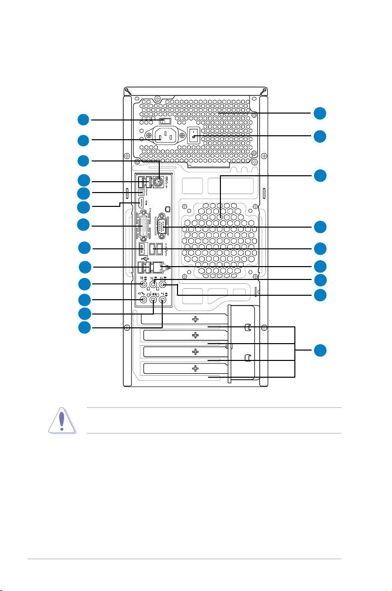
1.3 Rear panel
The system rear panel includes the power connector and several I/O ports that
allow convenient connection of devices.
10
1
2
6
7
8
9
11
14
15
16
17
3
4
5
12
7
7
13
18
19
20
Do NOT cover the rear vent , and the ambience temperature is limited up to
35oC to prevent the system from overheating.
1. Voltage selector.
This switch allows you to adjust the system input voltage
according to the voltage supply in your area. See the section “Voltage
selector” on page 1-7 before adjusting this switch.
2. Power connector.
3. Power supply unit fan vent.
This connector is for the power cable and plug.
This vent is for the PSU fan that provides
ventilation inside the power supply unit.
4. Power Switch.
1-4 Chapter 1: System introduction
This switch is for switching on/off the power supply unit.
5. Chassis fan vent. This vent is for the fan that provides ventilation inside the
system chassis.
6. PS/2 keyboard port.
7. USB 2.0 ports 1, 2, 3, 4, 5, and 6.
This purple 6-pin connector is for a PS/2 keyboard.
These 4-pin Universal Serial Bus (USB)
ports are available for connecting USB 2.0 devices.
8. Optical S/PDIF Out port.
This port connects an external audio output device
via an optical S/PDIF cable.
9. HDMI port.
This port is for a High-Denition Multimedia Interface (HDMI)
connector, and is HDCP compliant allowing playback of HD DVD, Blu-Ray
and other protected content.
10. DVI pot.
This port is for any DVI-D compatible device. DVI-D can not be
converted to output RGB Signal to CRT and is not compatible with DVI-I.
Dual display output support
• This table indicates that whether the following dual display outputs are
supported for your motherboard:
Dual display outputs Supported Not supported
DVI + D-Sub •
DVI + HDMI •
• During POST, only the monitor connected to the D-Sub port has display.
Playback of HD DVD and Blu-Ray Discs
• For better playback quality, we recommend that you follow the system
HDMI + D-Sub •
The dual display function works only under Windows.
requirements listed below.
Suggested list
CPU AMD® Athlon 4400+
DIMM DDR2 800 (1GB or higher)
BIOS setup Frame Buffer Size--256MB or higher
Playback
software
CyberLink® PowerDVD 7.3
(not supporting video acceleration)
File format
Non-protected clips 1920 x 1080p 1920 x 1080p
HD-DVD 1920 x 1080p 1280 x 1080p
• Supported DVD formats: VC-1, H.264, and MPEG-2.
• To play HD DVD or Blu-Ray Disc, ensure to use HDCP compliant devices
Blu-Ray 1280 x 1080p 1280 x 1080p
and softwares.
Best resolution
Windows XP Windows Vista
1-5ASUS V4-M3N8200
11. ESATA port.
12. VGA port.
This port connects an external Serial ATA hard disk.
This 15-pin port is for a VGA monitor or other VGA-compatible
devices.
13. LAN (RJ-45) port.
This port allows Gigabit connection to a Local Area
Network (LAN) through a network hub.
14. Side Speaker Out port (gray).
This port connects the sie speakers in an
8-channel audio conguration.
15. Microphone port (pink).
16. Line Out port (lime).
This port connects a microphone.
This port connects a headphone or a speaker.
In 4-channel and 6-channel conguration, the function of this port becomes
Front Speaker Out.
17. Line In port (light blue).
This port connects the tape, CD, DVD player, or
other audio sources.
18. Rear Speaker Out port (black).
This port connects the rear speakers in a
4-channel, 6-channel, or 8-channel audio conguration.
19. Center / Subwoofer port (orange).
This port connects the center /
subwoofer speakers.
Refer to the audio conguration table below for the function of the audio ports in
2, 4, 6, or 8-channel conguration.
Audio 2, 4, 6, or 8-channel conguration
Port
Light Blue Line In Surround Out Line In Line In
Lime Line Out Front Speaker Out Front Speaker Out Front Speaker Out
Pink Mic In Mic In Mac In Mac In
Orange - -
Black - Rear Speaker Out
Gray - -
20. Expansion slot covers.
Headset
2-channel
4-channel 6-channel 8-channel
Center/ Subwoofer Center/ Subwoofer
Rear Speaker Out Rear Speaker Out
- Side Speaker Out
Remove these covers when installing expansion
cards.
1-6 Chapter 1: System introduction
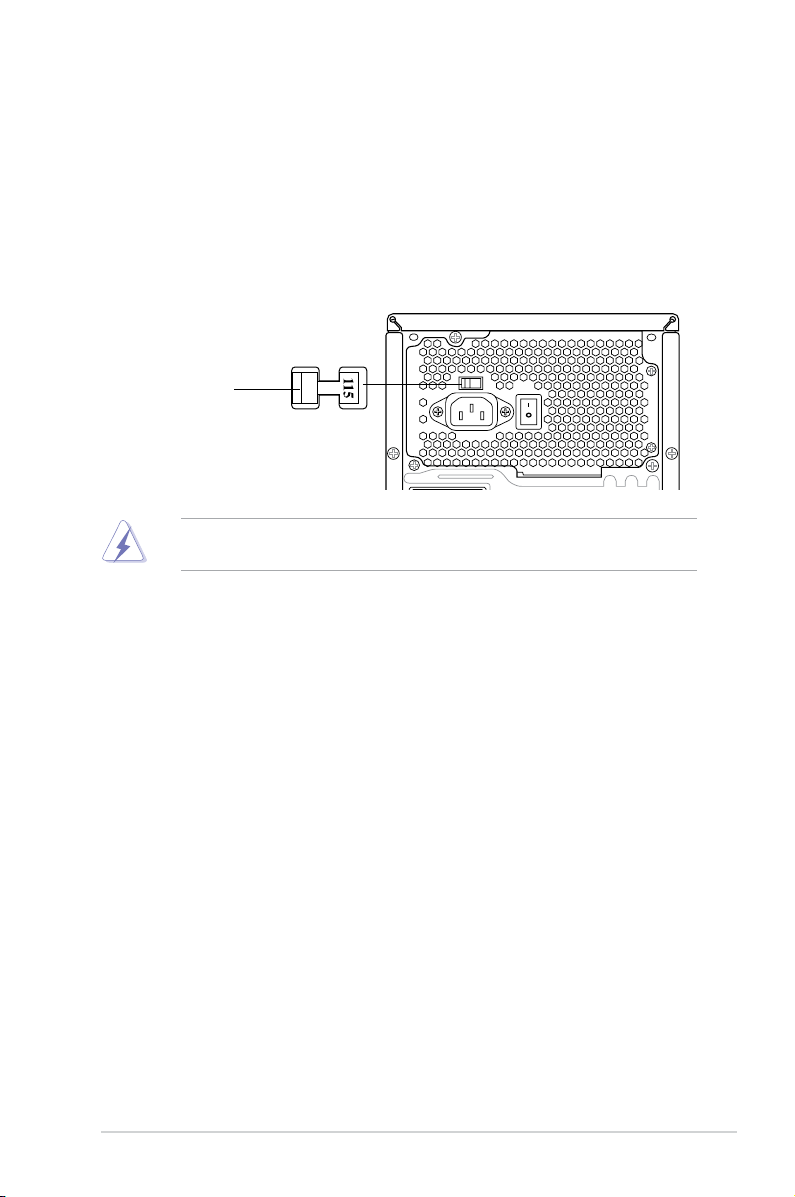
Voltage selector
The PSU has a 115 V/230 V voltage selector switch located beside the power
connector. Use this switch to select the appropriate system input voltage according
to the voltage supply in your area.
If the voltage supply in your area is 100-127 V, set this switch to 115 V.
If the voltage supply in your area is 200-240 V, set this switch to 230 V.
115V/230V
Voltage selector
Setting the switch to 115V in a 230V environment or 230V in a 115V
environment will seriously damage the system!
1-7ASUS V4-M3N8200
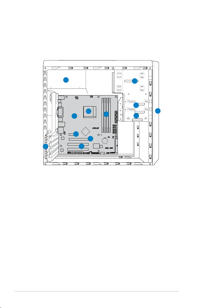
1.4 Internal components
R
R
The illustration below is the internal view of the system when you remove the top
cover and the power supply unit. The installed components are labeled for your
reference. Proceed to Chapter 2 for instructions on installing additional system
components.
5
8
9
12
11
1. Front panel cover
2. 5.25-inch optical drive bays
3. Floppy disk drive bay
4. Hard disk drive bay
5. Power supply unit
6. CPU socket
2
3
6
10
7
4
1
7. DIMM sockets
8. ASUS motherboard
9. PCI Express x1 slot
10. PCI Express x16 slot
11. PCI slots
12. Metal bracket lock
1-8 Chapter 1: System introduction
Chapter 2
This chapter provides step-by-step
instructions on how to install
components in the system.
Basic installation
2.1 Preparation
R
Onboard LED
SB_PWR
ON
Standby
Power
OFF
Powered
Off
Before you proceed, make sure that you have all the components you plan to
install in the system.
Basic components to install
1. Central Processing Unit (CPU)
2. DDR2 Dual Inline Memory Module (DIMM)
3. Expansion card(s)
4. Hard disk drive
5. Optical drive
6. Floppy disk drive
Tool
Phillips (cross) screw driver
2.2 Before you proceed
Take note of the following precautions before you install components into the
system.
•
Use a grounded wrist strap or touch a safely grounded object or a metal
object, such as the power supply case, before handling components to
avoid damaging them due to static electricity.
•
Hold components by the edges to avoid touching the ICs on them.
•
Whenever you uninstall any component, place it on a grounded antistatic
pad or in the bag that came with the component.
The motherboard comes with an onboard standby power LED. This LED lights
up to indicate that the system is ON, in sleep mode or in soft-off mode, and not
powered OFF. Unplug the power cable from the power outlet and make sure that
the standby power LED is OFF before installing any system component.
2-2 Chapter 2: Basic installation
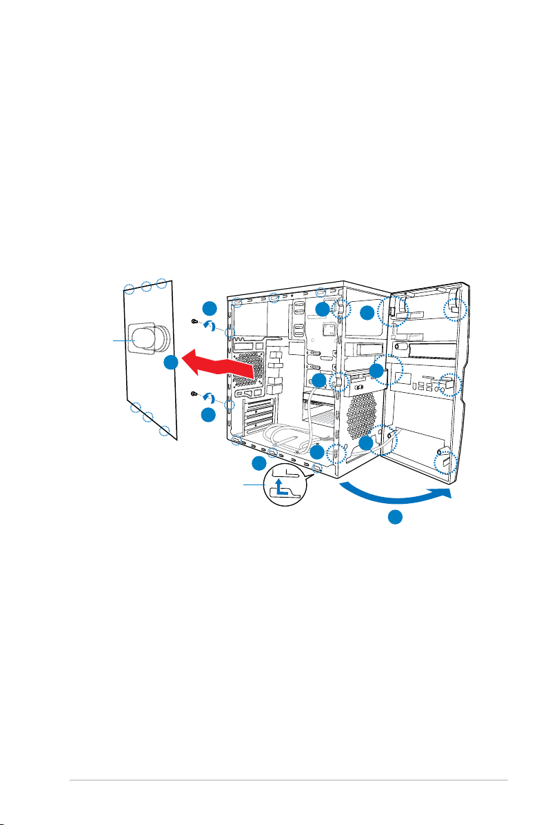
2.3 Removing the side cover and front
panel assembly
Follow the steps below to remove the side cover and front panel assembly.
1. Remove the cover screws on the rear panel.
2. Pull the side cover toward the rear panel until its hooks disengage from the
chassis tab holes. Set the side cover aside.
3. Locate the front panel assembly hooks, then lift them until they disengage
from the chassis.
4. Swing the front panel assembly to the right, until the hinge-like tabs on the
right side of the assembly are exposed.
5. Remove the front panel assembly, then set it aside.
Air duct
1
2
1
Chassis tab holes
3
3
3
2
4
4
4
4
2-3ASUS V4-M3N8200
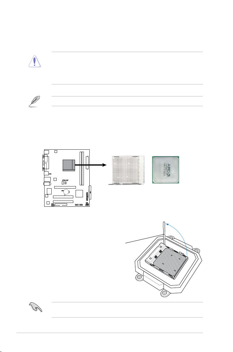
2.4 Central Processing Unit (CPU)
R
CPU Socket AM2+
The motherboard comes with a 940-pin AM2+ socket designed for the AMD
Athlon™ 64 X2/Athlon™ 64/Sempron™ processor.
The AM2+ socket has a different pinout from the 940-pin socket designed for
the AMD Opteron™ processor. Make sure you use a CPU is designed for the
AM2+ socket. The CPU ts in only one correct orientation. DO NOT force the
CPU into the socket to prevent bending the connectors on the socket and
damaging the CPU!
AM2+ socket is backward compatible with AM2 socket.
2.4.1 Installing the CPU
To install a CPU:
1. Locate the CPU socket on the motherboard.
2. Unlock the socket by pressing the
lever sideways, then lift it up to a
90º angle.
Socket lever
Make sure that the socket lever is lifted up to a 90º angle; otherwise, the CPU
2-4 Chapter 2: Basic installation
will not t in completely.
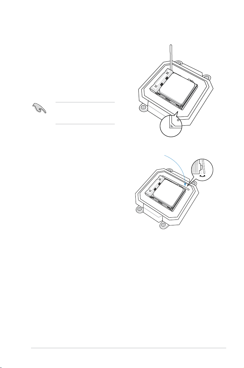
3. Position the CPU above the socket
such that the CPU corner with the
gold triangle matches the socket
corner with a small triangle.
4. Carefully insert the CPU into the
socket until it ts in place.
Please make sure your CPU
is fully plugged-in to reduce
abnormal symptom.
5. When the CPU is in place, push
down the socket lever to secure the
CPU. The lever clicks on the side tab
to indicate that it is locked.
6. Install a CPU heatsink and fan
following the instructions that came
with the heatsink package.
2-5ASUS V4-M3N8200
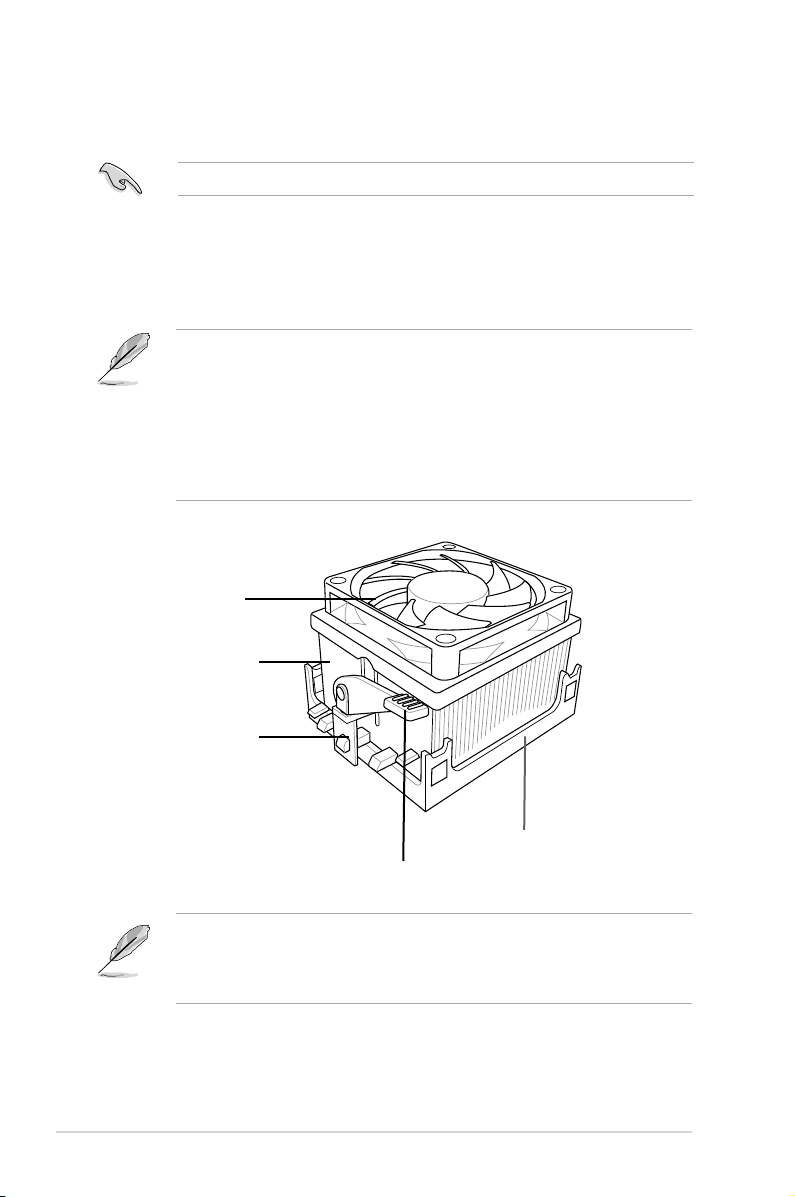
2.4.2 Installing the heatsink and fan
Make sure that you use only AMD-certied heatsink and fan assembly.
Follow these steps to install the CPU heatsink and fan.
1. Place the heatsink on top of the installed CPU, making sure that the heatsink
ts properly on the retention module base.
• The retention module base is already installed on the motherboard
upon purchase.
• You do not have to remove the retention module base when installing the
CPU or installing other motherboard components.
• If you purchased a separate CPU heatsink and fan assembly, make
sure that a Thermal Interface Material is properly applied to the CPU
heatsink or CPU before you install the heatsink and fan assembly.
CPU Fan
CPU Heatsink
Retention bracket
Retention Module Base
Retention bracket lock
Your boxed CPU heatsink and fan assembly should come with installation
instructions for the CPU, heatsink, and the retention mechanism. If the
instructions in this section do not match the CPU documentation, follow the
latter.
2-6 Chapter 2: Basic installation
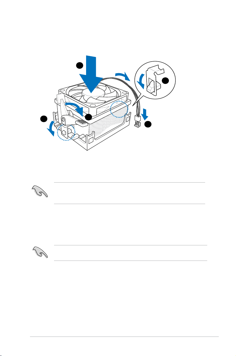
2. Attach one end of the retention bracket to the retention module base.
1
3
4
5
2
3. Align the other end of the retention bracket (near the retention bracket lock)
to the retention module base. A clicking sound denotes that the retention
bracket is in place.
Make sure that the fan and heatsink assembly perfectly ts the retention
mechanism module base, otherwise you cannot snap the retention bracket in
place.
4. Push down the retention bracket lock on the retention mechanism to secure
the heatsink and fan to the module base.
5. When the fan and heatsink assembly is in place, connect the CPU fan cable
to the connector on the motherboard labeled CPU_FAN.
Do not forget to connect the CPU fan connector! Hardware monitoring errors
can occur if you fail to plug this connector.
2-7ASUS V4-M3N8200
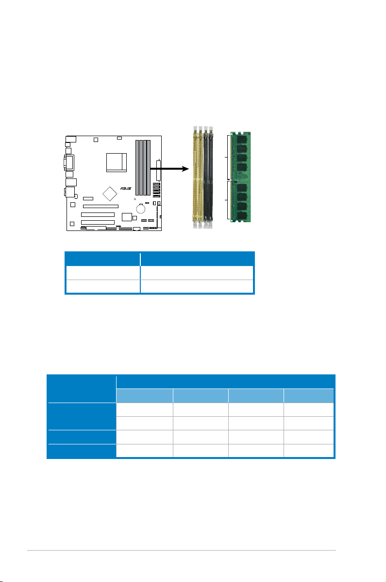
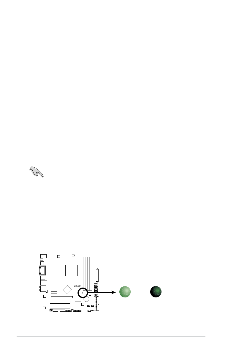
2.5 Installing a DIMM
R
240-pin DDR2 DIMM Sockets
DIMM_B1
DIMM_A2
DIMM_B2
DIMM_A1
128 Pins
112 Pins
The system motherboard comes with four Double Data Rate 2 (DDR2) Dual Inline
Memory Module (DIMM) sockets.
The following gure illustrates the location of the sockets:
Channel Sockets
Channel A DIMM_A1 and DIMM A2
Channel B DIMM_B1 and DIMM B2
2.5.1 Memory congurations
You may install 256 MB, 512 MB, 1 GB, and 2 GB unbuffered ECC and non-ECC
DDR2 DIMMs into the DIMM sockets.
Recommended Memory Congurations
Mode
Single-Channel
DIMM_A1 DIMM_B1 DIMM_A2 DIMM_B2
– Populated – –
Populated – – –
Dual-channel (1) Populated Populated – –
Dual-channel (2) Populated Populated Populated Populated
2-8 Chapter 2: Basic installation
Sockets
• When using only one memory module, start installing the DDR2 DIMM from
slot DIMM_A1 or DIMM_B1 for better overclocking capability.
• For dual-channel conguration (2), you may:
- install identical DIMMs in all four sockets OR
- install identical DIMM pair in DIMM_A1 and DIMM_B1 (yellow sockets)
and another identical DIMM pair in DIMM_A2 and DIMM_B2 (black
sockets)
• Due to the chipset’s limitation, the 1066 MHz memory modules run at 1066
MHz only when:
- two 1066 MHz memory modules installed in the same colored-slots
(either in the yellow slots or black slots); and
- one 1066 MHz memory module installed in any of the slots.
In other cases, the 1066 MHz memory modules can only run at
800 MHz.
• Always use identical DDR2 DIMM pairs for dual channel mode. For
optimum compatibility, we recommend that you obtain memory modules
from the same vendor.
• If you are using a Windows 32-bit version operating system (e.g. 32-bit
Windows, 32-bit Vista), the system will allocate a certain amount of memory
space for system devices.
When installing total memory of 4GB capacity or more, Windows
•
®
32-bit
operation system may only recognize less than 3GB. Hence, a total
installed memory of less than 3GB is recommended.
The motherboard can support 8 GB physical memory on the operating system
listed below. You may install a maximum of 2 GB DIMMs on each slot.
64-bit
Windows® XP Professional x64 Edition
Windows® Vista x64 Edition
2-9ASUS V4-M3N8200
Qualied Vendors Lists (QVL)
DDR2-533 MHz capability
Size Vendor Model CL Brand SS/
512MB Kingston KVR533D2N4/512 N/A Inneon SS HYB18T512800AF3733336550 · ·
512MB Samsung M378T6553BG0-CD5 4 Samsung SS K4T51083QB-GCD5 · ·
1G HY HYMP512U64CP8-C4 AB 4 Hynix DS HY5PS12821CFP-C4 · ·
512MB Micron MT 16HTF6464AG-53EB2 4 Micron DS D9BOM · ·
1G Corsair VS1GB533D2 N/A Corsair DS 64M8CFEGQIB0900718 · ·
512MB Elpida EBE51UD8ABFA-5C-E N/A Elpida SS E5108AB-5C-E · ·
512MB Transcend 512MB ECC N/A Micron SS 6ND22D9GCT(ECC) · ·
512MB ADATA M2OAD2G3H3166I1B52 N/A ADATA SS AD29608A8A-37DG20719 · ·
DS
Component DIMM support
A* B* C*
DDR2-667 MHz capability
Size Vendor Model CL Brand SS/
2G Kingston KVR667D2N5/2G N/A Micron DS 7RE22 D9HNL · ·
512MB Samsung M378T6553CZ3-CE6 N/A Samsung SS K4T51083QC-ZCE6 · ·
2G Qimonda HYS64T256020EU-3S-B 5 Qimonda DS HTB18T1G800BF-3S3VV10907 · ·
1G Corsair VS1GB667D2 N/A Corsair DS MID095D62864M8CEC · ·
1G HY HYMP512U72AP8-Y5 N/A Hynix DS HY5PS12821AFP-Y5(ECC) · ·
1G HY HYMP512U64CP8-Y5 AB 5 Hynix DS HY5PS12521CFP-Y5 · ·
512MB Kingmax KLCC28F-A8KB5 N/A Kingmax SS KKEA88B4LAUG-29DX · ·
512MB Apacer AU512E667C5KBGC 5 Apacer SS AM4B5708MIJS7E0627B · ·
1G Apacer AU01GE667C5KBGC 5 Apacer DS AM4B5708MIJS7E0627B · ·
512MB ADATA M20AD5G3H3166I1C52 N/A ADATA SS AD29608A8A-3EG20648 · ·
512MB ADATA M20AD5G3H3166I1C52 N/A ADATA SS AD29608A8A-3EG20718 · ·
512MB VDATA M2GVD5G3H31A4I1C52 N/A VDATA SS VD29608A8A-3EC20615 · ·
1G VDATA M2GVD5G3I41C4I1C52 N/A VDATA DS VD29608A8A-3EC20620 · ·
1G PSC AL7E8E63B-6E1K 5 PSC DS A3R12E3GEF637BLC5N · ·
1G PSC AL7E8F73C-6E1 5 PSC SS A3R1GE3CFF734MAA0J · ·
512MB Nanya NT512T64U88A1BY-3C N/A Nanya SS NT5TU64M8AE-3C · ·
1G Kingtiger E0736001024667 N/A Kingtiger DS KTG667PS6408NST-C6 GDBTX · ·
1G Kingston KHX6400D2LL/1G N/A Kingston DS Heat-Sink Package · ·
1G Samsung KR M378T2953CZ3-CE7 N/A Samsung DS K4T51083QC-ZCE7 · ·
1G Samsung KR M391T2953CZ3-CE7 N/A Samsung DS K4T51083QC-ZCE7(ECC) · ·
512MB Qimonda HYS64T64000EU-2.5-B2 6 Qimonda SS HYB18T512800B2F25FSS28380 · ·
1G Micron MT18HTF12872AY-80ED4 5 Micron DS 6TD22D9GKX(ECC) · ·
1G Corsair XMS2-6400 5 Corsair DS Heat-Sink Package · ·
DS
(continued on the next page)
Component DIMM support
A* B* C*
2-10 Chapter 2: Basic installation
Qualied Vendors Lists (QVL)
DDR2-800 MHz capability
Size Vendor Model CL Brand SS/
1G HY HYMP512U64AP8-S6 AA N/A Hynix DS HY5PS12821AFP-S6 · ·
2G Apacer 78.A1GA0.9K4 5 Apacer DS AM4B5808CQJS8E0740E · ·
512MB ADATA M20AD6G3H3160I1E58 N/A ADATA SS AD29608A8A-25EG80720 · ·
1G VDATA M2GVD6G3I4170I1E53 N/A VDATA DS VD29608A8A-25EG30647 · ·
1G PSC AL7E8F73C-8E1 5 PSC SS A3R1GE3CFF734MAA0E · ·
DS
Component DIMM support
A* B* C*
DDR2-1066 MHz capability
Size Vendor Model CL Brand SS/
512MB Kingston KHX8500D2/512 N/A Kingston SS Heat-Sink Package · · ·
512MB Kingston KHX8500D2K2/1GN N/A Kingston SS Heat-Sink Package · ·
1G Kingston KHX8500D2K2/2GN N/A Kingston DS Heat-Sink Package · · ·
1G Qimonda HYS64T128020EU-19F-C 6 Qimonda DS HYB18T512800CF19FFSS24313 · · ·
1G Corsair CM2X1024-8500C5 N/A Corsair DS Heat-Sink Package · ·
1G Corsair CM2X1024-8500C5D 5 Corsair DS Heat-Sink Package · · ·
512MB ADATA M2OMIDG3H3160INC5Z 5 ADATA SS Heat-Sink Package · · ·
1G ADATA M2OMIDG314720INC5Z 5 ADATA DS Heat-Sink Package · · ·
1G OCZ OCZ2N10662GK N/A OCZ DS Heat-Sink Package · · ·
1G GEIL M016E2864T2AGXAKT7G330520 5 Micron DS 7KD22D9GMH · · ·
DS
• Due to AM2+ CPU limitation, only one DDR2 1066 DIMM is supported per
channel. When four DDR2 DIMMs are installed, all DIMMs run at 800MHz
frequency by default for system stability.
• The default DIMM frequency depends on its Serial Presence Detect (SPD),
which is the standard way of accessing information from a memory module.
Under the default state, some memory modules for overclocking may
operate at a lower frequency than the vendor-marked value.
Component DIMM support
A* B* C*
SS - Single-sided / DS - Double - sided
DIMM support:
• A*: Supports one module inserted into any slot as Single-channel memory
conguration.
• B*: Supports one pair of modules inserted into either the yellow slots or the
black slots as one pair of Dual-channel memory conguration.
• C*: Supports four modules inserted into both the yellow slots and the black
slots as two pairs of Dual-channel memory conguration.
Visit the ASUS website for the latest DDR2-533/667/800/1066MHz QVL.
2-11ASUS V4-M3N8200
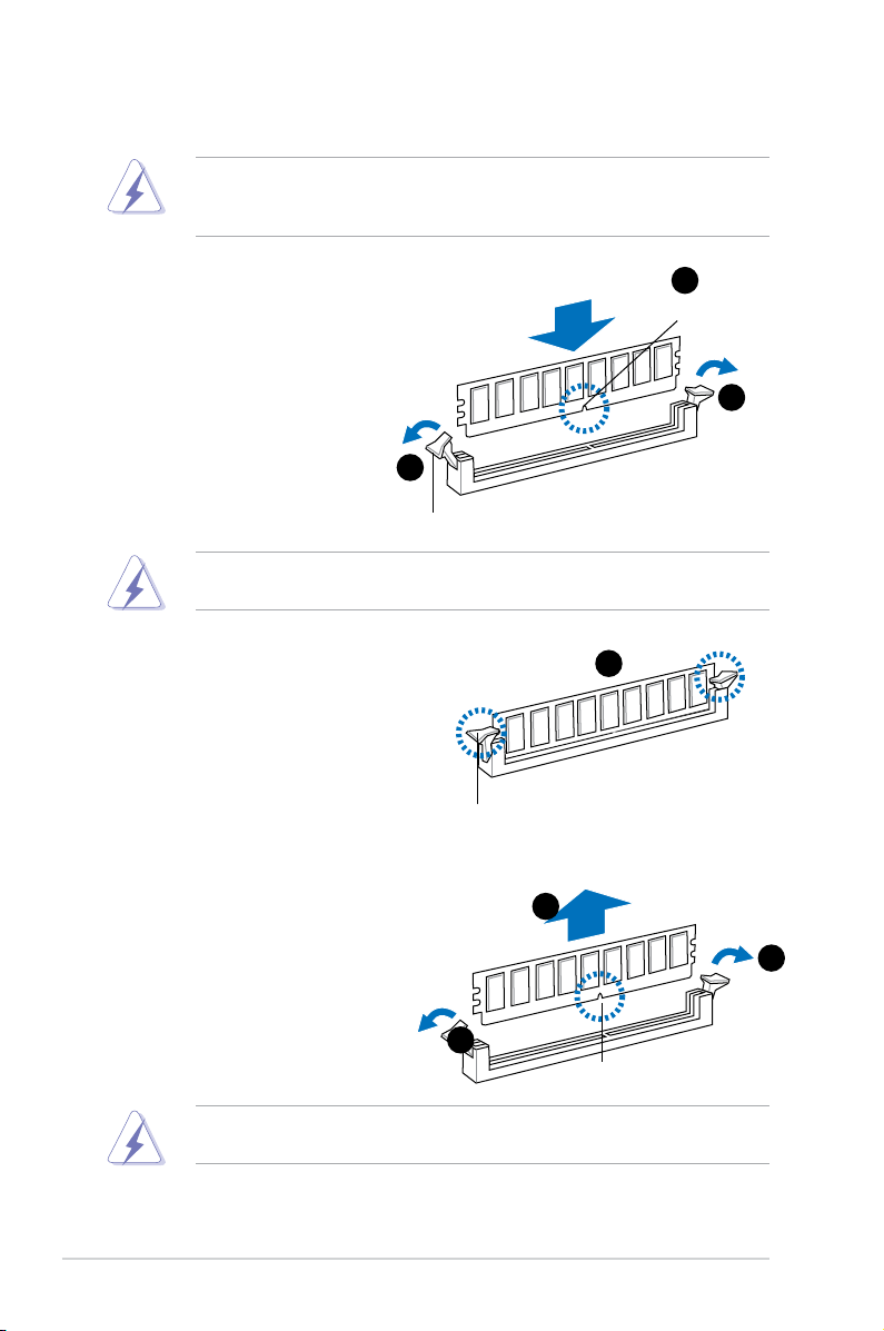
2.5.2 Installing a DDR2 DIMM
Make sure to unplug the power supply before adding or removing DIMMs or
other system components. Failure to do so may cause severe damage to both
the motherboard and the components.
1. Unlock a DDR2 DIMM socket
by pressing the retaining clips
outward.
2. Align a DIMM on the socket
such that the notch on the
DIMM matches the break on
the socket.
1
Unlocked retaining clip
A DDR2 DIMM is keyed with a notch so that it ts in only one direction. DO
NOT force a DIMM into a socket to avoid damaging the DIMM.
3. Firmly insert the DIMM into the
socket until the retaining clips snap
back in place and the DIMM is
properly seated.
Locked Retaining Clip
2.5.3 Removing a DDR2 DIMM
Follow these steps to remove a DIMM.
2
DDR2 DIMM notch
1
3
2
1. Simultaneously press the
1
retaining clips outward to unlock
the DIMM.
1
DDR2 DIMM notch
Support the DIMM lightly with your ngers when pressing the retaining clips.
The DIMM might get damaged when it ips out with extra force.
2. Remove the DIMM from the socket.
2-12 Chapter 2: Basic installation
 Loading...