

ASUS TUEP2-M User Manual

®
TUEP2-M
Intel® 815EP Chipset
microATX Motherboard
USER’S MANUAL

USER'S NOTICE
No part of this manual, including the products and software described herein, may be reproduced, transmitted, transcribed, stored in a retrieval system, or translated into any language in
any form or by any means, except for documentation kept by the purchaser for backup purposes,
without the expressed written permission of ASUSTeK COMPUTER INC. (“ASUS”).
ASUS PROVIDES THIS MANUAL “AS IS” WITHOUT WARRANTY OF ANY KIND,
EITHER EXPRESSED OR IMPLIED, INCLUDING BUT NOT LIMITED TO THE
IMPLIED W ARRANTIES OR CONDITIONS OF MERCHANT ABILITY OR FITNESS FOR
A PARTICULAR PURPOSE. IN NO EVENT SHALL ASUS, ITS DIRECTORS, OFFICERS,
EMPLOYEES OR AGENTS BE LIABLE FOR ANY INDIRECT, SPECIAL, INCIDENTAL, OR CONSEQUENTIAL DAMAGES (INCLUDING DAMAGES FOR LOSS OF
PROFITS, LOSS OF BUSINESS, LOSS OF USE OR DATA, INTERRUPTION OF BUSINESS AND THE LIKE), EVEN IF ASUS HAS BEEN ADVISED OF THE POSSIBILITY
OF SUCH DAMAGES ARISING FROM ANY DEFECT OR ERROR IN THIS MANUAL
OR PRODUCT.
Product warranty or service will not be extended if: (1) the product is repaired, modified or
altered, unless such repair, modification or alteration is authorized in writing by ASUS; or (2)
the serial number of the product is defaced or missing.
Products and corporate names appearing in this manual may or may not be registered trademarks or copyrights of their respective companies, and are used only for identification or
explanation, for the owners’ benefit, without intent to infringe.
• Adobe and Acrobat are registered trademarks of Adobe Systems Incorporated.
• Intel, LANDesk, and Pentium are registered trademarks of Intel Corporation.
• Trend and ChipAwayVirus are trademarks of Trend Micro, Inc.
• Windows and MS-DOS are registered trademarks of Microsoft Corporation.
• ADI and SoundMAX are trademarks of Analog Devices, Inc..
The product name and revision number are both printed on the product itself. Manual revi-
sions are released for each product design represented by the digit before and after the period
of the manual revision number. Manual updates are represented by the third digit in the manual
revision number.
For more information on manuals, BIOS, drivers, or recent product releases, contact ASUS at
http://www.asus.com.tw or through any of the means indicated on the following page.
SPECIFICATIONS AND INFORMATION CONTAINED IN THIS MANUAL ARE FURNISHED FOR INFORMATIONAL USE ONLY, AND ARE SUBJECT TO CHANGE AT
ANY TIME WITHOUT NOTICE, AND SHOULD NOT BE CONSTRUED AS A COMMITMENT BY ASUS. ASUS ASSUMES NO RESPONSIBILITY OR LIABILITY FOR
ANY ERRORS OR INACCURACIES THAT MA Y APPEAR IN THIS MANUAL, INCLUDING THE PRODUCTS AND SOFTWARE DESCRIBED IN IT.
Copyright © 2001 ASUSTeK COMPUTER INC. All Rights Reserved.
Product Name: ASUS TUEP2-M
Manual Revision: 1.01 E807
Release Date: September 2001
2 ASUS TUEP2-M User’s Manual

ASUS CONTACT INFORMATION
ASUSTeK COMPUTER INC. (Asia-Pacific)
Marketing
Address: 150 Li-Te Road, Peitou, Taipei, Taiwan 112
Telephone: +886-2-2894-3447
Fax: +886-2-2894-3449
Email: info@asus.com.tw
Technical Support
MB/Others (Tel): +886-2-2890-7121 (English)
Notebook (Tel): +886-2-2890-7122 (English)
Desktop/Server (Tel): +886-2-2890-7123 (English)
Fax: +886-2-2890-7698
Newsgroup: cscnews.asus.com.tw
Email: tsd@asus.com.tw
WWW: www.asus.com.tw
FTP: ftp.asus.com.tw/pub/ASUS
ASUS COMPUTER INTERNATIONAL (America)
Marketing
Address: 6737 Mowry Avenue, Mowry Business Center, Building 2
Newark, CA 94560, USA
Fax: +1-510-608-4555
Email: tmd1@asus.com
Technical Support
Fax: +1-510-608-4555
Email: tsd@asus.com
WWW: www.asus.com
FTP: ftp.asus.com/Pub/ASUS
ASUS COMPUTER GmbH (Europe)
Marketing
Address: Harkortstr. 25, 40880 Ratingen, BRD, Germany
Fax: +49-2102-442066
Email: sales@asuscom.de (for marketing requests only)
Technical Support
Hotline: MB/Others: +49-2102-9599-0 Notebook: +49-2102-9599-10
Fax: +49-2102-9599-11
Support (Email): www.asuscom.de/de/support (for online support)
WWW: www.asuscom.de
FTP: ftp.asuscom.de/pub/ASUSCOM
3ASUS TUEP2-M User’s Manual

CONTENTS
1. INTRODUCTION ............................................................................. 7
1.1 How This Manual Is Organized .................................................. 7
1.2 Item Checklist ............................................................................. 7
2. FEATURES ........................................................................................ 8
2.1 The ASUS TUEP2-M ................................................................ 8
2.2 TUEP2-M Motherboard Components .................................... 12
3. HARDWARE SETUP ...................................................................... 14
3.1 TUEP2-M Motherboard Layout ............................................. 14
3.2 Layout Contents ........................................................................ 15
3.3 Hardware Setup Procedure ....................................................... 17
3.4 Motherboard Settings................................................................ 17
3.5 System Memory (DIMM) ......................................................... 24
3.5.1 General DIMM Notes .................................................... 24
3.5.2 Memory Installation ...................................................... 25
3.6 Central Processing Unit (CPU) ................................................. 26
3.7 Expansion Cards ....................................................................... 27
3.7.1 Expansion Card Installation Procedure ......................... 27
3.7 Expansion Cards ....................................................................... 27
3.7.1 Expansion Card Installation Procedure ......................... 27
3.7.2 Assigning IRQs for Expansion Cards............................ 28
3.7.3 Communication and Networking Riser (CNR) Slot...... 29
3.8 Connectors ................................................................................. 30
3.8.1 External Connectors ...................................................... 30
3.8.2 Internal Connectors ......................................................... 34
3.9 Starting Up the First Time ........................................................ 43
4. BIOS SETUP..................................................................................... 45
4.1 Managing and Updating Your BIOS ......................................... 45
4.1.1 Upon First Use of the Computer System....................... 45
4.1.2 Updating BIOS Procedures ........................................... 47
4.2 BIOS Setup Program ................................................................ 49
4.2.1 BIOS Menu Bar ............................................................. 50
4.2.2 Legend Bar .................................................................... 50
4 ASUS TUEP2-M User’s Manual

CONTENTS
4.3 Main Menu................................................................................ 52
4.3.1 Primary & Secondary Master/Slave .............................. 53
4.3.2 Keyboard Features......................................................... 56
4.4 Advanced Menu ........................................................................ 58
4.4.1 Chip Configuration ........................................................ 61
4.4.2 I/O Device Configuration .............................................. 64
4.4.3 PCI Configuration ......................................................... 66
4.4.4 Shadow Configuration................................................... 68
4.5 Power Menu .............................................................................. 69
4.5.1 Power Up Control.......................................................... 71
4.5.2 Hardware Monitor ......................................................... 73
4.6 Boot Menu ................................................................................ 74
4.7 Exit Menu ................................................................................. 76
5. SOFTWARE SETUP ....................................................................... 79
5.1 Operating Systems .................................................................... 79
5.1.1 Windows 98 First Time Installation .............................. 79
5.2 TUEP2-M Motherboard Support CD ....................................... 79
5.2.1 Installation Menus ......................................................... 79
5.2.2 Applications................................................................... 80
6. SOFTWARE REFERENCE ........................................................... 83
6.1 ASUS PC Probe ........................................................................ 83
6.1.1 Starting ASUS PC Probe ............................................... 83
6.1.2 Using ASUS PC Probe .................................................. 84
6.1.3 ASUS PC Probe Task Bar Icon ..................................... 87
6.2 Winbond Smart Manager ........................................................... 89
6.3 CyberLink PowerPlayer SE ...................................................... 93
6.4 CyberLink V ideoLive Mail ....................................................... 94
6.5 ASUS LiveUpdate .................................................................... 96
7. APPENDIX........................................................................................ 97
7.1 Glossary .................................................................................... 97
INDEX ................................................................................................. 101
5ASUS TUEP2-M User’s Manual

FCC & DOC COMPLIANCE
Federal Communications Commission Statement
This device complies with FCC Rules Part 15. Operation is subject to the following
two conditions:
• This device may not cause harmful interference, and
• This device must accept any interference received, including interference that
may cause undesired operation.
This equipment has been tested and found to comply with the limits for a Class B
digital device, pursuant to Part 15 of the FCC Rules. These limits are designed to
provide reasonable protection against harmful interference in a residential installation. This equipment generates, uses and can radiate radio frequency energy and, if
not installed and used in accordance with manufacturer's instructions, may cause
harmful interference to radio communications. However, there is no guarantee that
interference will not occur in a particular installation. If this equipment does cause
harmful interference to radio or television reception, which can be determined by
turning the equipment off and on, the user is encouraged to try to correct the interference by one or more of the following measures:
• Re-orient or relocate the receiving antenna.
• Increase the separation between the equipment and receiver.
• Connect the equipment to an outlet on a circuit different from that to which the
receiver is connected.
• Consult the dealer or an experienced radio/TV technician for help.
WARNING! Any changes or modifications to this product not expressly ap-
proved by the manufacturer would void any assurances on its safety or
performance and could result in violation of Part 15 of the FCC Rules.
Reprinted from the Code of Federal Regulations #47, part 15.193, 1993. W ashington DC: Of fice of the
Federal Register, National Archives and Records Administration, U.S. Government Printing Office.
Canadian Department of Communications Statement
This digital apparatus does not exceed the Class B limits for radio noise emissions
from digital apparatus set out in the Radio Interference Regulations of the Canadian
Department of Communications.
This Class B digital apparatus complies with Canadian ICES-003.
Cet appareil numérique de la classe B est conforme à la norme NMB-003 du Canada.
6 ASUS TUEP2-M User’s Manual
1. INTRODUCTION
1.1 How This Manual Is Organized
This manual is divided into the following sections:
1. INTRODUCTION Manual information and checklist
2. FEATURES Production information and specifications
3. HARDWARE SETUP Instructions on setting up the motherboard.
4. BIOS SETUP Instructions on setting up the BIOS
5. SOFTWARE SETUP Instructions on setting up the included software
6. SOFTWARE REFERENCE Reference material for the included software
7. APPENDIX Optional items and general reference
1.2 Item Checklist
Check that your package is complete. If you discover damaged or missing items,
contact your retailer.
Manual / Checklist
1. INTRODUCTION
Package Contents
(1) ASUS Motherboard
(1) 40-pin 80-conductor ribbon cable
for internal UltraDMA100/66/33
IDE drives
(1) Ribbon cable for (1) 5.25” and (2)
3.5” floppy disk drives
(1) Serial COM2 connector with
bracket
(1) Bag of spare jumpers
(1) Support drivers and utilities
(1) User’s Manual
(1) ASUS 2-port USB connector set
with bracket
(1) I/O Port bracket
Optional Items
ASUS iPanel
ASUS IrDA-compliant infrared module
Smart Card Reader
ASUS TUEP2-M User’s Manual
7

2.1 The ASUS TUEP2-M
The ASUS TUEP2-M motherboard is carefully designed for the demanding PC user
who wants advanced features processed by the fastest processors.
2.1.1 Specifications
• Latest Intel Processor Support
2. FEATURES
Specifications
• North Bridge System Chipset: The Intel
• South Bridge System Chipset: The Intel
• Intel
• PC100/PC133 Memory Support: Equipped with three Dual Inline Memory
2. FEATURES
®
PIII
Tualatin™ 133/100MHz FSB FC-PGA2
PIII® Coppermine™ 133/100MHz FSB FC-PGA
Celeron™ 100/66MHz FSB FC-PGA
®
82815EP Memory Controller Hub
(MCH) chipset supports 66/100/133 Front Side Bus (FSB), up to 512MB of
PC100/PC133 SDRAM, and AGP 4X interface which delivers twice the amount
of data than the current AGP standard.
®
82801BA I/O Controller Hub (ICH2)
delivers twice the I/O bandwidth, and supports UltraDMA/100, allowing burst
mode data transfer rates of up to 100MB/sec. Two USB controllers provide up
to four USB ports.
®
Accelerated Hub Architecture: Features a dedicated high speed hub
link between the ICH2 and MCH with a bandwidth of 266MB/sec – twice the
maximum bandwidth of the PCI bus.
Module (DIMM) sockets which support PC133/PC100 non-ECC SDRAMs
(available in 64, 128, 256, 512Mb densities) up to 512MB.
• UltraDMA33/66/100 Support: Comes with an onboard PCI Bus Master IDE
controller with two connectors that support four IDE devices on two channels.
Supports UltraDMA/100, UltraDMA/66, UltraDMA/33, PIO Modes 3 & 4 and
up to four ATAPI devices like DVD-ROM, CD-ROM, CD-R/RW, LS-120, and
tape backup drives.
• ASUS JumperFree™ Mode: Allows processor settings and easy overclocking
of frequency and Vcore voltage all through BIOS setup when JumperFree™
mode is enabled. Easy-to-use DIP switches instead of jumpers are included to
allow manual adjustment of the processor external frequency.
• Wake-Up Support: Supports Wake-On-LAN and Wake-On-Ring, Keyboard
Wake-Up, and BIOS Wake-Up.
• Around-the-Clock Intrusion Detection: Chassis intrusion circuitry can log
chassis open events into LDCM. The onboard battery supports detection even
when normal power is removed and through a new design, battery drain is even
lower than the RTC used for keeping time!
• PC Health Monitoring: Provides an easy way to examine and manage system
status information, such as CPU and system voltages, temperatures, and fan
status through the onboard hardware ASUS ASIC and the bundled ASUS PC
Probe or Intel LDCM software.
8
ASUS TUEP2-M User’s Manual

2. FEATURES
• CNR Support: A Communication and Networking Riser (CNR) slot provides
an interface to support very affordable multichannel audio, V.90 analog modem,
Home PNA, 10/100 Ethernet networking, USB hub, as well as future technologies
such as xDSL.
• PCI Expansion Slots: Provides three 32-bit PCI (PCI 2.2 compliant) expansion
slots. All PCI slots can support Bus Master PCI cards, such as SCSI or LAN
cards. (PCI supports up to 133MB/s maximum throughput.)
• Super Multi-I/O: Provides two high-speed UART compatible serial ports and
one parallel port with EPP and ECP capabilities. UART2 can also be directed
from COM2 to the Infrared Module for wireless connections. The Super I/O
controller also supports a floppy disk dirve, PS/2 keyboard, and PS/2 mouse.
• Smart BIOS: 2Mbit firmware gives a new easy-to-use interface which provides
more control and protection over the motherboard. Provides Vcore and CPU/
SDRAM frequency adjustments, boot block write protection, and HD/SCSI/MO/
ZIP/CD/Floppy boot selection. Hardware random number generator supports new
security software for data protection and secured Internet transactions.
• Enhanced ACPI & Anti-Boot Virus Protection: Programmable BIOS (Flash
EEPROM), offering enhanced ACPI for Windows 98 compatibility, built-in
firmware-based virus protection, and autodetection of most devices for virtually
automatic setup.
• Onboard LED: The onboard LED lights up when there is standby power to the
motherboard. This acts as a reminder to the user to turn OFF the power before
plugging and unplugging devices so as not to damage the motherboard,
peripherals, and/or components.
Specifications
2. FEATURES
• Onboard Audio: Audio models come with the AC ’97-compliant interfaces
that support integrated audio and modem features that comprise digital audio
engine with 3D-hardware accelerator, on-chip sample rate converter, and a
professional wavetable.
• Easy Connectivity and System Information Access: Supports an optional
ASUS iPanel, an easy-to-access box with system diagnostic display area, system
status LEDs, USB ports, and hot keys. The AFPANEL connector on the
motherboard accommodates the ASUS iPanel.
• Smartcard Reader Connector: Features a connector that provides the
convenience of financial, telephony , and traveling services through the optional
Smartcard Reader interface.
• SMBus: Features the System Management Bus interface that physically
transports commands and information between SMBus devices.
ASUS TUEP2-M User’s Manual
9

2. FEATURES
2.1.2 Specifications–Optional Components
The following onboard components are optional at the time of purchase:
• Smart Networking: Features 3Com’s 3C920 Fast Ethernet controller, which
supports Wired for Management, remote wake-up, and OnNow initiatives to
reduce Total Cost of Ownership (TCO).
• Onboard Audio: AC’97 Audio chipset supports the latest audio sound circuitry .
2. FEATURES
Performance
A software package helps setup the multi-channel PC sound system.
2.1.3 Performance
• UltraPerformance: Onboard IDE Bus Master controller with two connectors that
support four IDE devices in two channels. Supports UltraDMA/100, UltraDMA/
66, UltraDMA/33 (IDE DMA Mode 2), PIO Modes 3 & 4, and supports Enhanced
IDE devices, such as DVD-ROM, CD-ROM, CD-R/R W , LS-120, and T ape Backup
drives.
• High-Speed Data Transfer Interface: IDE transfers using UltraDMA/66 Bus
Master IDE can handle rates up to 66.6MB/s. This motherboard with its chipset
and support for UltraDMA/100 increases the data transfer rate to 100MB/s.
UltraDMA/100 is backward compatible with DMA/66, DMA/33, and DMA and
with existing DMA devices and systems so there is no need to upgrade current
EIDE/IDE drives and host systems. (UltraDMA/66/100 requires a 40-pin 80conductor cable to be enabled.)
• Concurrent PCI: Concurrent PCI allows multiple PCI transfers from PCI master
buses to memory and processor.
• SDRAM Optimized Performance: This motherboard supports PC133-
compliant Synchronous Dynamic Random Access Memory (SDRAM), which
increases the data transfer rate to 1066MB/s max.
• ACPI Ready: Advanced Configuration and Power Interface (ACPI) is also
implemented on all ASUS smart series motherboards. ACPI provides more Ener gy
Saving Features for future operating systems (OS) supporting OS Direct Power
Management (OSPM) functionality . W ith these features implemented in the OS,
PCs can be ready around the clock, yet satisfy all the energy saving standards.
To fully utilize the benefits of ACPI, an ACPI-supported OS, such as Windows
98, must be used.
• Suspend and Go: Suspend-to-RAM (STR) provides maximum power savings
as an alternative to leaving the computer ON and QuickStart™ so that you do
not have to wait for a long time for system bootup.
• Stepless Frequency Selection: Allows CPU external (FSB) frequency settings
to be raised or lowered in MHz increments.
10
ASUS TUEP2-M User’s Manual

2. FEATURES
• PC’99 Compliant: Both the BIOS and hardware levels of ASUS smart series
motherboards are PC’99 compliant. The new PC’99 requirements for systems
and components are based on the following high-level goals: support for Plugn-Play capability and power management for configuring and managing all system
components, and 32-bit device drivers and installation procedures for
Windows95/98/NT . Color-coded connectors and descriptive icons make
identification easy as required by PC’99.
2.1.4 Intelligence
• Fan Status Monitoring and Alarm: To prevent system overheat and system
damage, the CPU, power supply, and system fans can be monitored for RPM
and failure. All the fans are set for its normal RPM range and alarm thresholds.
• Voltage Monitoring and Alert: System voltage levels are monitored to ensure
stable current to critical motherboard components. Voltage specifications are
more critical for future processors, so monitoring is necessary to ensure proper
system configuration and management.
Intelligence
2. FEATURES
• System Resources Alert: Windows 98, Windows NT, and OS/2, require much
more memory and hard disk space to present enormous user interfaces and run
large applications. The onboard hardware ASUS ASIC in conjunction with either
the bundled ASUS PC Probe or Intel LDCM, will warn you before the system
resources are used up to prevent possible application crashes.
• Dual Function Power Button: Through BIOS, the power button can be defined
as the “Stand by” (a.k.a. Suspend or Sleep) button or as the Soft-Off button (see
ATX Power / Soft-Off Switch Lead in 3.8 Connectors for more information).
Regardless of the setting, pushing the power button for more than 4 seconds allows
the computer to enter the Soft-Off mode.
• Remote Ring On (requires modem): This allows a computer to be turned on
remotely through an internal or external modem. With this benefit on hand, you
can access any information from their computers from anywhere in the world.
• Message LED (requires ACPI OS support): Message LEDs now act as
information providers. Through the way a particular LED illuminates, you can
determine if a message has been received from a fax/modem. A simple glimpse
provides useful information. This function requires ACPI OS and driver support.
• Peripheral Power Up: Keyboard or Mouse power up can be enabled or disabled
through BIOS setup to allow the computer to be powered ON using your keyboard
or mouse click.
ASUS TUEP2-M User’s Manual
11

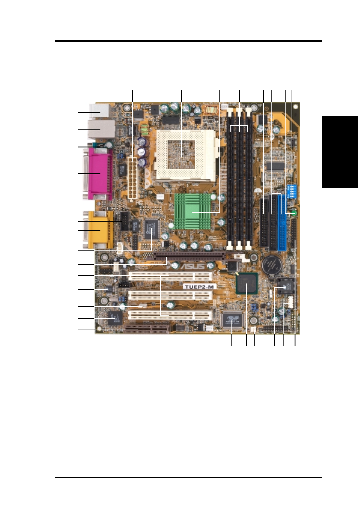
2.2 TUEP2-M Motherboard Components
See opposite page for locations.
Processor Support Socket 370 for Pentium III/Celeron/Tualatin CPUs................. 2
MB Components
2. FEATURES
2. FEATURES
Location
Feature Setting DIP Switches ................................................... 8
Chipsets Intel 82815EP Memory Controller Hub (MCH) ...................... 3
Intel 82801BA I/O Controller Hub (ICH2) .......................... 13
2Mbit Firmware Hub (FWH) ................................................. 11
Low Pin Count (LPC) Multi-I/O Chipset ............................... 21
Main Memory 3 DIMM Sockets (maximum 512MB support) ........................ 4
PC133 SDRAM support
Expansion Slots 3 PCI Slots .............................................................................. 19
1 Communications & Network Riser (CNR) Slot .................. 15
1 Accelerated Graphics Port Slot 9 (AGP)............................. 20
System I/O 1 USB Header ......................................................................... 10
1 Floppy Disk Drive Connector ............................................... 5
2 IDE Connectors (UltraDMA/100 Support) ........................... 6
1 Serial COM2 Header ........................................................... 23
1 ASUS iPanel Connector ........................................................ 9
1 Parallel Port Connector ............................................. (Top) 24
1 Serial COM1 Port Connector .............................. (Bottom) 25
2 USB Port Connectors .......................................... (Bottom) 26
1 PS/2 Mouse Connector .............................................. (Top) 27
1 PS/2 Keyboard Connector ................................... (Bottom) 27
Audio AC’97 Audio Codec............................................................. 18
1 Game/MIDI Connector.............................................. (Top) 22
1 Line Out Connector ............................................. (Bottom) 22
1 Line In Connector................................................ (Bottom) 22
1 Microphone Connector ........................................ (Bottom) 22
Network Features 3Com 3C920 Fast Ethernet Controller ................................... 16
Wake-On-LAN Connector...................................................... 17
Wake-On-Ring Connector ...................................................... 12
RJ-45 Connector ...................................................... (Top) 26
Hardware Monitoring System Voltage Monitoring (integrated in ASUS ASIC) ....... 14
3 Fan Power and Speed Monitoring Connectors
Power ATX Power Supply Connector ................................................. 1
Onboard LED ........................................................................... 7
Form Factor micro A TX
12
ASUS TUEP2-M User’s Manual
2. FEATURES
2.2.1 Component Locations
27
26
25
24
23
22
21
1
2345
86
7
2. FEATURES
Component Location
20
19
18
17
16
15
14 91213 11
10
ASUS TUEP2-M User’s Manual
13
3. HARDWARE SETUP
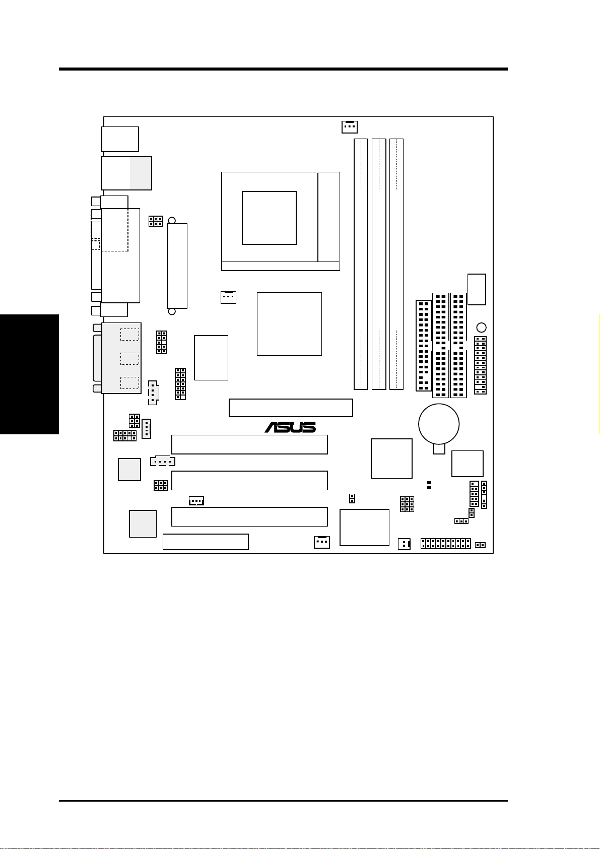
3.1 TUEP2-M Motherboard Layout
PS/2KBMS
T: Mouse
B: Keyboard
USB
T: USB1
B: USB2
COM1
Motherboard Layout
3. H/W SETUP
GAME_AUDIO
AAPANEL
Audio
Codec
Top:
RJ-45
USBPWR1
KBPWR
PARALLEL PORT
Line
Out
Line
In
AUX
Mic
In
HEADPHONE
MIC2
AUD_EN
LAN_EN
3Com
3C920
Fast
Ethernet
ATX Power Connector
COM2
SMARTCARD
MODEM
CD
CNR_SLOT
PWR_FAN
Super
I/O
WOL_CON
CPU_FAN
Socket 370
Intel 815EP
Memory
Controller
Hub (MCH)
Accelerated Graphics Port (AGP)
®
PCI1
TUEP2-M
PCI2
PCI3
CHA_FAN
SECONDARY IDE
FLOPPY
DIMM1 (64/72 bit, 168-pin module)
DIMM2 (64/72 bit, 168-pin module)
DIMM3 (64/72 bit, 168-pin module)
1
0
3
2
5
Controller
JTPWR
ASUS ASIC
with
Hardware
Monitor
4
Intel I/O
Hub
(ICH2)
WOR
1
CR2032 3V
Lithium Cell
CMOS Power
CLRTC
CNRUSB1
CNRUSB2
JEN
USBPWR2
PANEL
ACHA
PRIMARY IDE
2Mbit
Firmware
(FWH)
USB2
DSW
11
Hub
IDELED
DIP
Switches
LED
AFPANEL
SMB
14
NOTE: The AC’97 audio codec, external GAME/AUDIO connectors, and
internal audio connectors are optional components, and present in audio
models only . The components are grayed in the above motherboard layout.
ASUS TUEP2-M User’s Manual

3. HARDWARE SETUP
3.2 Layout Contents
Motherboard Settings
1) JEN p. 18 JumperFree™ Mode (Enable/Disable)
2) USBPWR1 p. 19 USB Device Wake Up (Enable/Disable)
USBPWR2
3) USBCNR1/USBCNR2 p. 19 USB/CNR Selection (USB2 Connect/CNR)
4) AUD_EN1 p. 20 Onboard Audio CODEC Setting (Enable/Disable)
5) LAN_EN p. 20 Onboard LAN Setting (Enable/Disable)
6) KBPWR p. 21 Keyboard Power Up (Enable/Disable)
7) DSW p. 22 CPU External Frequency Setting
Expansion Slots
1) DIMM 1/2/3 p. 24 168-Pin System Memory Support
2) CPU p. 26 Central Processing Unit (CPU)6
3) PCI1/2/3 p. 27 32-bit PCI Bus Expansion Slots
4) CNR1 p. 28 Communication and Network Riser Slot
External Connectors
1) PS2KBMS p. 30 PS/2 Mouse Connector (6-pin female)
2) PS2KBMS p. 30 PS/2 Keyboard Connector (6-pin female)
3) USB p. 31 Universal Serial Bus Ports (Two 4-pin female)
4) PRINTER p. 31 Parallel Port Connector (25-pin female)
5) COM1/COM2 p. 32 Serial Port Connectors (9-pin male, 10-1 pin)
6) GAME_AUDIO p. 33 Game/MIDI Connector (15-pin female) (optional)
7) LINE-IN, -OUT, MIC p. 33 Audio Port Connectors (Three 1/8” female) (optional)
8) RJ-45 p. 33 Fast Ethernet Port Connector (optional)
Internal Connectors
1) FLOPPY p. 34 Floppy Disk Drive Connector (34-1pins)
2) PRIMARY/SECONDARY IDE p. 35 Primary/Secondary IDE Connectors (Two 40-1pins)
3) IDELED p. 35 IDE Activity LED (2 pins)
4) CPU_FAN, PWR_FAN p. 35 CPU, Power Supply , Chassis Fan Connectors (Three 3-pin)
CHA_FAN
5) CD1, AUX, MODEM p. 36 InternalAudio Connectors (optional)
6) HEADPHONE p. 36 Headphone True-Level Line Out Header (3 pins)
7) MIC2 p. 37 Internal Microphone Connector (3 pins)
3. H/W SETUP
Layout Contents
8) AFPANEL p. 37 ASUS iPanel Connector (24-1 pins)
9) AAPANEL p. 37 ASUS iPanel Audio Connector (10-1 pins)
10) SMB p. 38 SMBus Connector (6-1 pins)
11) ACHA p. 38 Chassis Intrusion Connector (2 pins)
12) WOL_CON p. 39 Wake-On-LAN Connector (3 pins)
13) WOR p. 39 Wake-On-Ring Connector (2 pins)
ASUS TUEP2-M User’s Manual
15

14) USB2 p. 40 USB Headers (5-1 pins)
15) ATXPWR p. 41 ATX Power Supply Connector (20 pins)
16) PWRLED (PANEL) p. 42 System Power LED Lead (3-1 pins)
17) KEYLOCK (PANEL) p. 42 Keyboard Lock Switch Lead (2 pins)
18) SPEAKER (PANEL) p. 42 System Warning Speaker Connector (4 pins)
19) MSG.LED (PANEL) p. 42 System Message LED (2 pins)
20) SMI (PANEL) p. 42 System Management Interrupt Switch Lead (2 pins)
21) PWRSW (PANEL) p. 42 ATX Power / Soft-Off Switch Lead (2 pins)
22) RESET (PANEL) p. 42 Reset Switch Lead (2 pins)
Layout Contents
3. H/W SETUP
3. HARDWARE SETUP
16
ASUS TUEP2-M User’s Manual
3. HARDWARE SETUP
3.3 Hardware Setup Procedure
Before using your computer, you must complete the following steps:
• Check Motherboard Settings
• Install Memory Modules
• Install the Central Processing Unit (CPU)
• Install Expansion Cards
• Connect Ribbon Cables, Panel Wires, and Power Supply
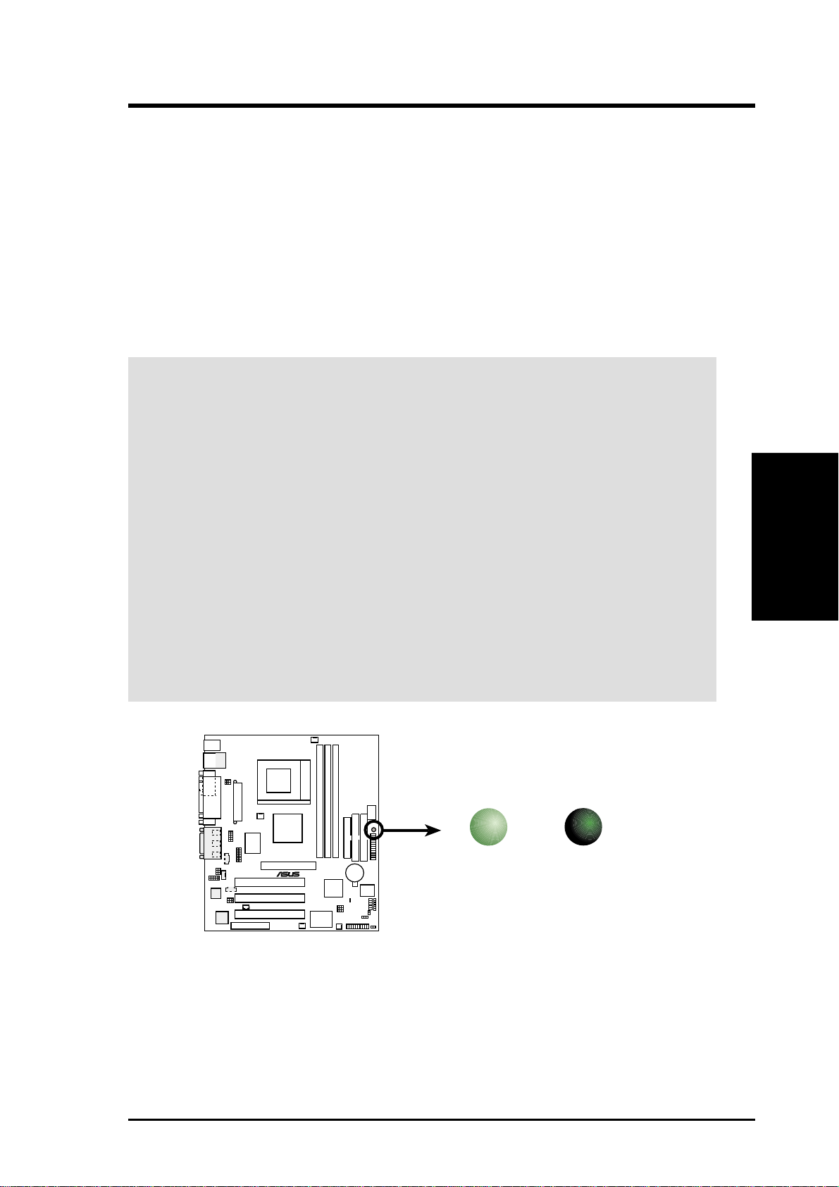
3.4 Motherboard Settings
WARNING! Computer motherboards and expansion cards contain very delicate
Integrated Circuit (IC) chips. T o protect them against damage from static electricity ,
you should follow some precautions whenever you work on your computer.
1. Unplug your computer when working on the internal components.
2. Use a grounded wrist strap or touch a safely grounded object or to a metal
object, such as the power supply case, before handling computer components.
3. Hold components by the edges and try not to touch the IC chips on them.
4. Whenever you install any component, place the components on a grounded
antistatic pad or in the bag that came with the components.
5. Before you install or remove any component, ensure that the ATX power
supply is switched off or the power cord is detached from the power
supply. Failure to do so may cause severe damage to the motherboard,
peripherals, and/or components.
LED
TUEP2-M
®
ON
Standby
Power
OFF
Powered
Off
3. H/W SETUP
Motherboard Settings
TUEP2-M Onboard LED
ASUS TUEP2-M User’s Manual
17
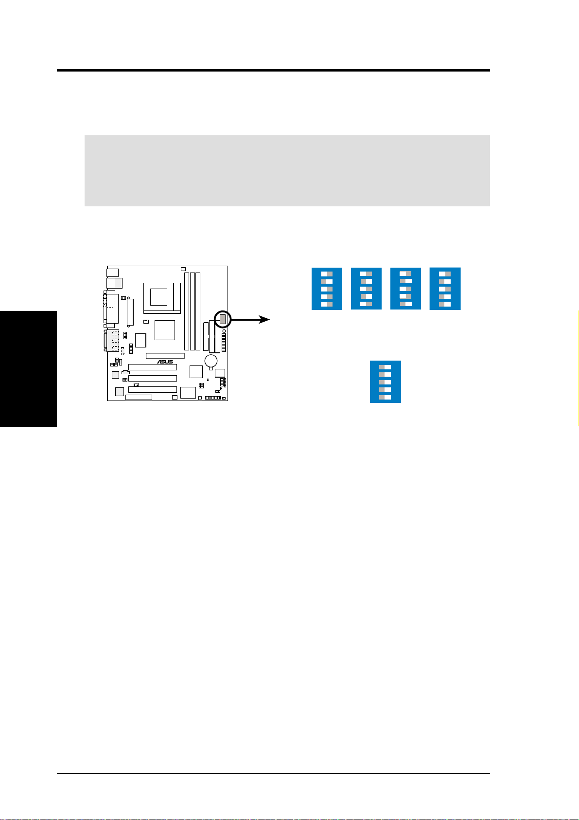
3. HARDWARE SETUP
Motherboard Feature Settings
The motherboard’s onboard functions are either adjusted through jumpers or DIP
switches. When using DIP switches, the white block represents the switch’s position.
The example below shows all the switches in the OFF position.
DSW
12345
ON
Motherboard Settings
TUEP2-M DIP Switches
3. H/W SETUP
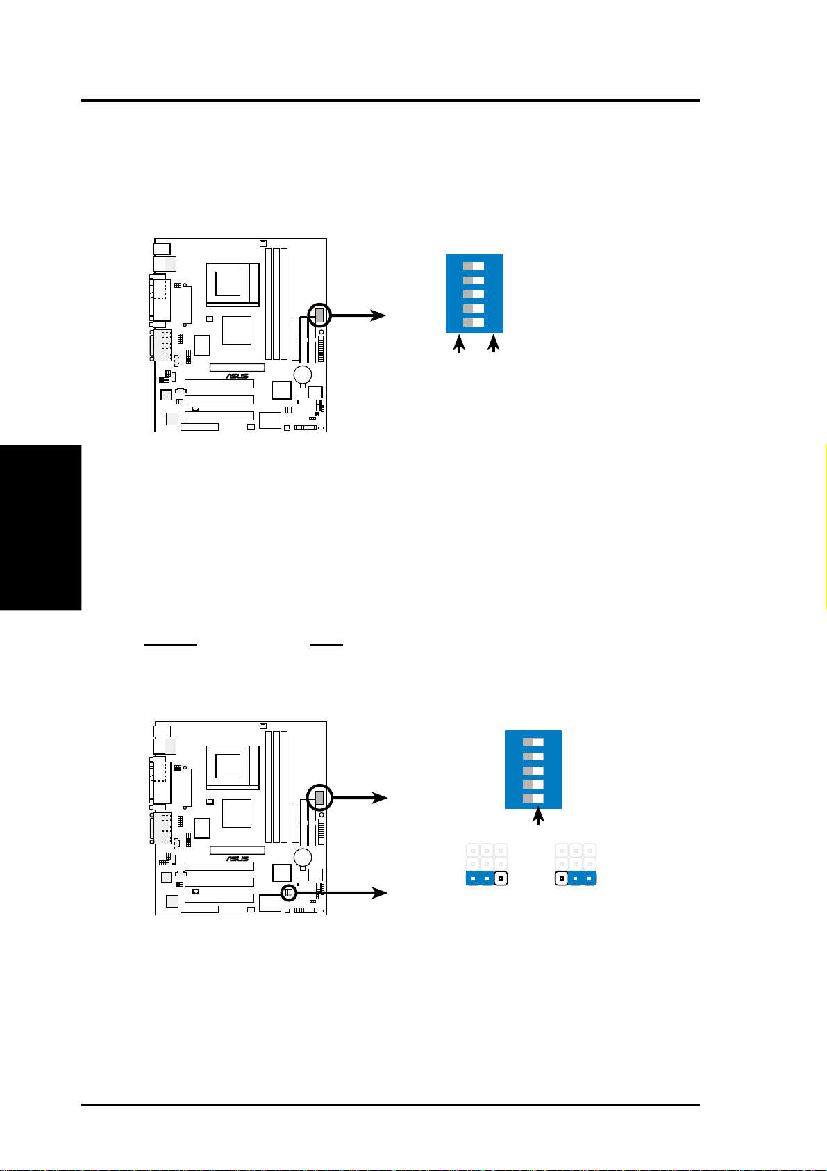
1) JumperFree™ Mode (JEN)
This jumper allows you to enable or disable the JumperFree™ mode. The
JumperFree™ mode allows processor settings to be made through the BIOS
setup (see 4.4 Advanced Menu).
NOTE: In JumperFree™ mode, all dip switches must be set to OFF.
Setting JEN
Disable (Jumper) [1-2]
Enable (JumperFree) [2-3] (default)
TUEP2-M
®
1. Frequency Selection
2. Frequency Selection
3. Frequency Selection
4. Frequency Selection
5. Frequency Selection.
ON OFF
DSW
18
®
TUEP2-M
TUEP2-M JumperFreeª Mode Setting
ASUS TUEP2-M User’s Manual
12
Disable
ON
OFF
JEN
12345
2
3
Enable
(default)
3. HARDWARE SETUP
2) USB Device Wake Up (USBPWR1,USBPWR2)
These allow you to disable or enable the USB device wake up function. Set these
jumpers to Enable if you wish to use your USB devices to wake up your computer .
This feature requires an A TX power supply that can supply at least 2A on the +5VSB
lead. The default is set to Disable because not all computers have the appropriate
ATX power supply. Your computer will not power ON if you set this to Enable and
do not have the appropriate ATX power supply . NOTE: This jumper must be set in
conjunction with W ake On USB for STR State in 4.5.1 Power Up Control.
NOTES
1. For suspend to RAM function, these jumpers must be set to Enable.
2. The total current consumed must NOT exceed the power supply capability
(+5VSB) whether under normal working conditions or in the sleep mode.
USBPWR1
2
1
2
3
®
TUEP2-M
TUEP2-M USB Device Wake Up
Disable
(Default)
USBPWR2
2
1
Disable
(Default)
Enable
2
Enable
3
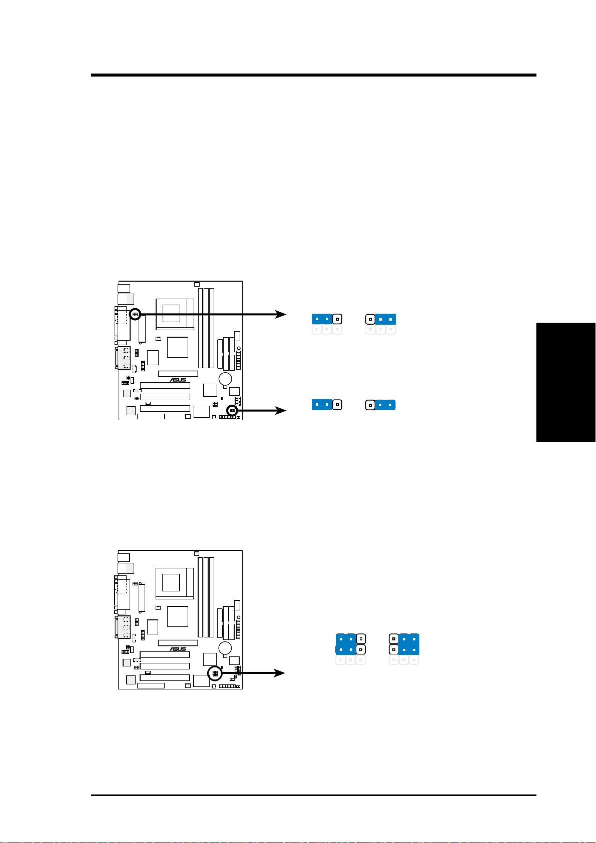
3) CNR/USB Selection (CNRUSB1/CNRUSB2)
The CNR slot can support an optional USB hub CNR card. If a USB hub CNR
card is used, set these jumpers to CNR. Otherwise, leave them on the default
setting of USB2 Connect.
CNRUSB1
TUEP2-M
CNRUSB2
®
12
2
3
3. H/W SETUP
Motherboard Settings
TUEP2-M USB/CNR Selection
ASUS TUEP2-M User’s Manual
(default)
CNRUSB2 Connect
19
4) Onboard Audio CODEC Setting (AUD_EN1)
(available on audio model only)
The onboard audio CODEC may be enabled or disabled using all of these jumpers.
Disable the onboard audio CODEC if you are using a PCI audio card on any of
the expansion slots or a primary audio/modem CNR on a CNR slot (see CNR
Slot later in this section). If using a PCI audio expansion card, Onboard AC97
Audio Controller in 4.4.2 I/O Device Configuration must also be disabled.
Setting AUD_EN1
Enable [1-2] (default)
Disable [2-3]
Motherboard Settings
3. H/W SETUP
3. HARDWARE SETUP
AUD_EN1
TUEP2-M
2
1
®
Enable
(Default)
2
3
Disable
TUEP2-M Audio Codec Setting
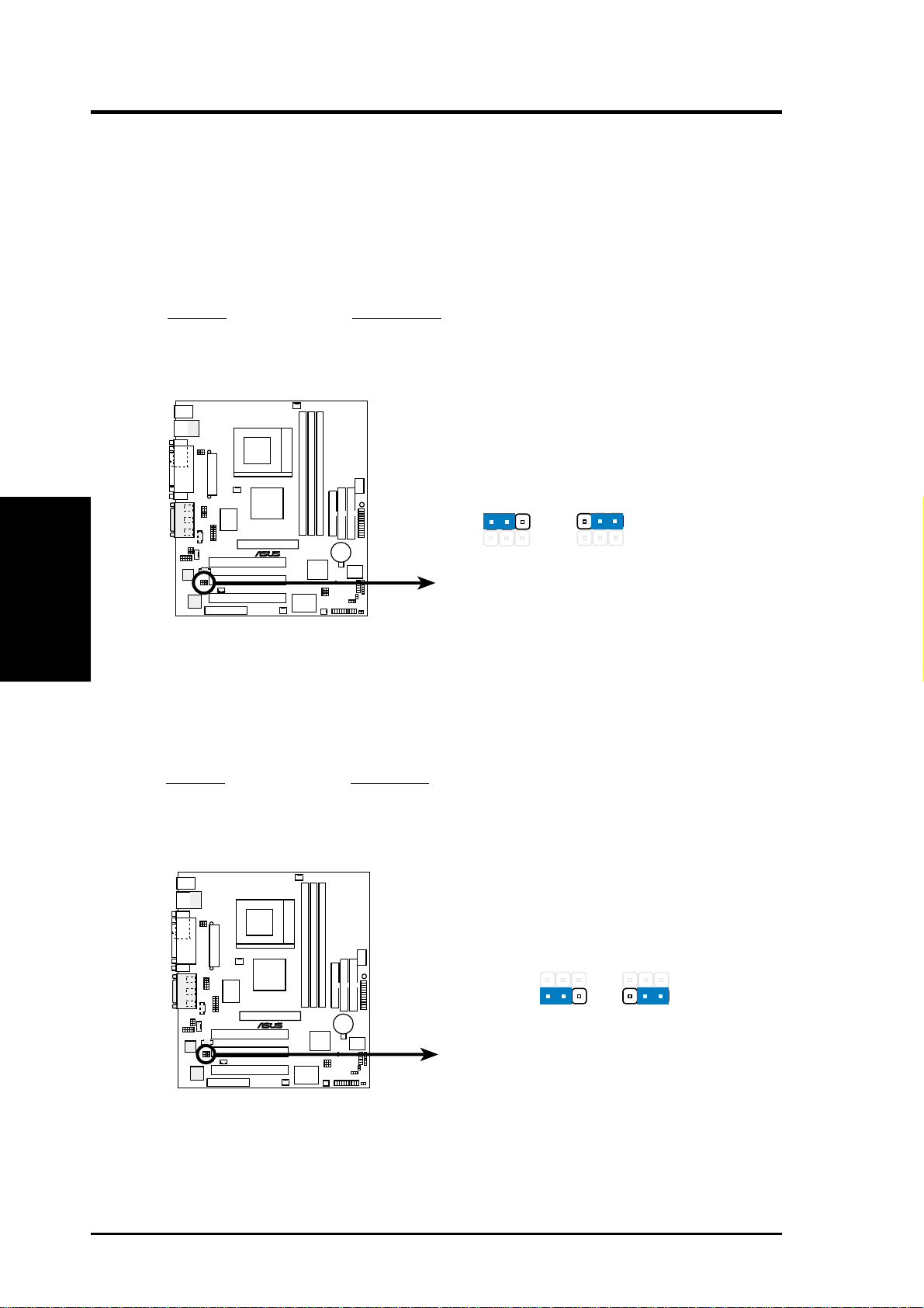
5) Onboard LAN Setting (LAN_EN)
The onboard LAN may be enabled/disabled with this jumper.
Setting LAN_EN
Enable [1-2] (default)
Disable [2-3]
LAN_EN
®
TUEP2-M
12
Enable
(default)
2
Disable
3
20
TUEP2-M On Board Lan Setting
ASUS TUEP2-M User’s Manual
3. HARDWARE SETUP
6) Keyboard Power Up (KBPWR)
This allows you to disable or enable the keyboard power up function. Set this
jumper to Enable if you wish to use your keyboard (by pressing <Spacebar>) to
power up your computer. This feature requires an ATX power supply that can
supply at least 300mA on the +5VSB lead. The default is set to Enable because
not all computers have the appropriate A TX power supply. Your computer will not
power ON if you set this to Enable b ut do not have the appropriate ATX power
supply. NOTE: This jumper must be set in conjunction with Wake On PS2 KB/
PS2 Mouse/CIR in 4.5.1 Power Up Control.
Setting KBPWR
Enable [1-2] (default)
Disable [2-3]
KBPWR
2
Disable
3
®
TUEP2-M
TUEP2-M Keyboard Power Setting
12
Enable
(default)
WARNING! Using a higher voltage may help when overclocking but may result
in the shortening of your computer component’s life. It is highly recommended
that you leave this setting on its default.
3. H/W SETUP
Motherboard Settings
ASUS TUEP2-M User’s Manual
21
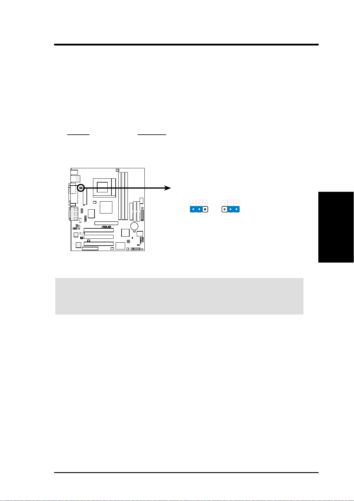
7) CPU External Frequency Setting (DSW)
This option tells the clock generator what frequency to send to the CPU, DRAM,
AGP , and the PCI bus. This allows the selection of the CPU’s External frequency.
IMPORTANT:
1. In JumperFree mode, all dip switches must be set to OFF.
2. When JumperFree mode is enabled, use BIOS setup in place of these switches
(see CPU Internal Frequency in 4.4 Advanced Menu).
NOTE: Only selected switches are illustrated. For a complete frequency listing,
see next page.
Motherboard Settings
3. H/W SETUP
3. HARDWARE SETUP
DSW
ON
12345
ON
12345
ON
CPU
SDRAM
AGP
PCI
®
TUEP2-M
66MHz
100MHz
66MHz
33MHz
100MHz
100MHz
66MHz
33MHz
133MHz
133MHz
66MHz
33MHz
12345
ON
133MHz
100MHz
66MHz
33MHz
12345
12345
ON
TUEP2-M CPU External
(JumperFree Mode)
Clock (BUS) Frequency Selection
NOTE: If your processor does not have a locked Frequency Multiple, you must
use CPU Cor e:Bus Freq. Multiple in 4.4 Advanced Menu to set the Frequency
Multiple. If the Frequency Multiple is locked, setting the Frequency Multiple in
BIOS setup will have no effect.
22
ASUS TUEP2-M User’s Manual

3. HARDWARE SETUP
External Frequency Table
The following table is for use by experienced motherboard installers only . Overclocking
can result in system instability or even shortening the life of the processor .
CPU:DRAM CPU SDRAM Frequency Selection Switches
Ratio (MHz) (MHz) 1 2 3 4 5
66:100 64.4 99.6 [ON] [O N] [ON ] [O N] [ON]
66:100 60.0 90.0 [ON] [O N] [ON ] [O N] [OFF]
66:100 66.0 100.0 [ON] [ON] [O N] [OFF] [ON]
66:100 68.3 102.5 [ON ] [ON] [ON] [OFF] [OFF]
66:100 70.0 105.0 [ON ] [ON] [OFF] [O N] [ON]
66:100 75.0 112.5 [ON] [O N] [OFF] [ON] [OFF]
66:100 80.0 120.0 [ON ] [ON] [OFF] [OFF] [ON]
66:100 83.0 124.5 [ON ] [ON] [OFF] [OFF] [OFF]
100:100 99.6 99.6 [ON ] [OFF] [ON ] [ON] [ON]
100:100 90.0 90.0 [ON ] [OFF] [ON ] [ON] [O FF]
100:100 100.0 100.0 [ON] [OFF] [ON] [OFF] [ON]
100:100 103.0 103.0 [ON] [OFF] [ON ] [OFF] [OFF]
100:100 105.0 105.0 [ON] [OFF] [OFF] [ON ] [ON]
100:100 110.0 110.0 [ON ] [OFF] [OFF] [ON ] [OFF]
100:100 115.0 115.0 [ON ] [OFF] [OFF] [OFF] [ON]
100:100 200.0 200.0 [ON] [OFF] [OFF] [OFF] [OFF]
133:133 132.8 132.8 [OFF] [ON] [O N] [O N] [O N]
133:133 166.6 166.6 [OFF] [ON] [O N] [O N ] [O FF]
133:133 133.0 133.0 [OFF] [ON] [O N] [OFF] [ON]
133:133 137.0 137.0 [OFF] [ON] [O N] [O FF] [O FF]
133:133 140.0 140.0 [OFF] [ON] [OFF] [O N ] [O N ]
133:133 145.0 145.0 [OFF] [ON] [OFF] [O N ] [O FF]
133:133 150.0 150.0 [OFF] [ON] [OFF] [O FF] [O N ]
133:133 160.0 160.0 [OFF] [ON] [OFF] [O FF] [O FF]
133:100 132.8 99.6 [OFF] [OFF] [O N ] [O N ] [O N]
133:100 166.6 125.0 [OFF] [OFF] [O N] [O N ] [O FF]
133:100 133.0 100.0 [OFF] [OFF] [O N ] [OFF] [O N ]
133:100 137.0 102.8 [OFF] [OFF] [O N] [O FF] [OFF]
133:100 140.0 105.0 [OFF] [OFF] [O FF] [O N ] [O N]
133:100 145.0 108.8 [OFF] [OFF] [O FF] [O N ] [O FF]
133:100 150.0 112.5 [OFF] [OFF] [O FF] [O FF] [O N ]
133:100 160.0 120.0 [OFF] [OFF] [O FF] [O FF] [O FF]
3. H/W SETUP
Motherboard Settings
For updated processor settings, visit ASUS’s web site (see ASUS CONTACT
INFORMATION)
ASUS TUEP2-M User’s Manual
23
3. HARDWARE SETUP
3.5 System Memory (DIMM)
NOTE: No hardware or BIOS setup is required after adding or removing memory.
This motherboard uses only Dual Inline Memory Modules (DIMMs). S ockets are
available for 3.3Volt (power level) unbuffered Synchronous Dynamic Random Access
Memory (SDRAM). One side (with memory chips) of the DIMM takes up one row on
the motherboard.
Memory speed setup is recommended through SDRAM Configuration in 4.4.1
Chip Configuration.
Install memory in any combination as follows:
DIMM Location 168-pin DIMM Total Memory
System Memory
3. H/W SETUP
Socket 1 (Rows 0&1) SDRAM 8, 16, 32, 64, 128, 256, 512MB x1
Socket 2 (Rows 2&3) SDRAM 8, 16, 32, 64, 128, 256, 512MB x1
Socket 3 (Rows 4&5) SDRAM 8, 16, 32, 64, 128, 256, 512MB x1
CAUTION! If the total installed memory exceeds 512MB, the system will hang
during startup.
3.5.1 General DIMM Notes
• For the system CPU bus to operate at 133MHz, use only PC133-compliant
• ASUS motherboards support SPD (Serial Presence Detect) DIMMs. This is the
Total System Memory (Max 512MB) =
DIMMs. When this motherboard operates at 133MHz, most system will not
even boot if non-compliant modules are used because of the strict timing issues
involved under this speed. If your DIMMs are not PC133-compliant, set the
CPU bus frequency to 100MHz RAM to ensure system stability.
memory of choice for best performance vs. stability.
• BIOS shows SDRAM memory on bootup screen.
• Single-sided DIMMs come in 16, 32, 64,128, 256MB; double-sided come in 32,
64, 128, 256, 512MB.
24
ASUS TUEP2-M User’s Manual
3. HARDWARE SETUP
3.5.2 Memory Installation
WARNING! Make sure that you unplug the power supply when adding or
removing memory modules or other system components. Failure to do so may
cause severe damage to both your motherboard and expansion cards (see 3.3
Hardware Setup Procedure for more information).
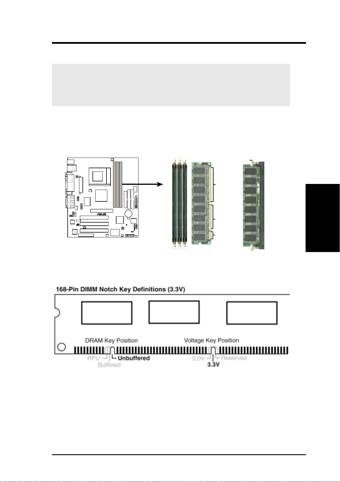
Insert the module(s) as shown. Because the number of pins are different on either
side of the breaks, the module will only fit in the orientation shown. DRAM SIMM
modules have the same pin contacts on both sides. SDRAM DIMMs have different
pin contacts on each side and therefore have a higher pin density.
Lock
88 Pins
®
TUEP2-M
TUEP2-M 168-Pin DIMM Sockets
60 Pins
20 Pins
The DIMMs must be 3.3Volt unbuffered SDRAMs. To determine the DIMM type,
check the notches on the DIMMs (see figure below).
The notches on the DIMM will shift between left, center, or right to identify the type
and also to prevent the wrong type from being inserted into the DIMM slot on the
motherboard. You must tell your retailer the correct DIMM type before purchasing.
This motherboard supports four clock signals per DIMM.
3. H/W SETUP
System Memory
ASUS TUEP2-M User’s Manual
25
3. H/W SETUP
CPU
3. HARDWARE SETUP
3.6 Central Processing Unit (CPU)
The motherboard provides a ZIF Socket 370. The CPU that came with the
motherboard should have a fan attached to it to prevent overheating. If this is not the
case, then purchase a fan before you turn on your system.
WARNING! Be sure that there is sufficient air circulation across the processor’s
heatsink by regularly checking that your CPU fan is working. W ithout sufficient
circulation, the processor could overheat and damage both the processor and the
motherboard. You may install an auxiliary fan, if necessary.
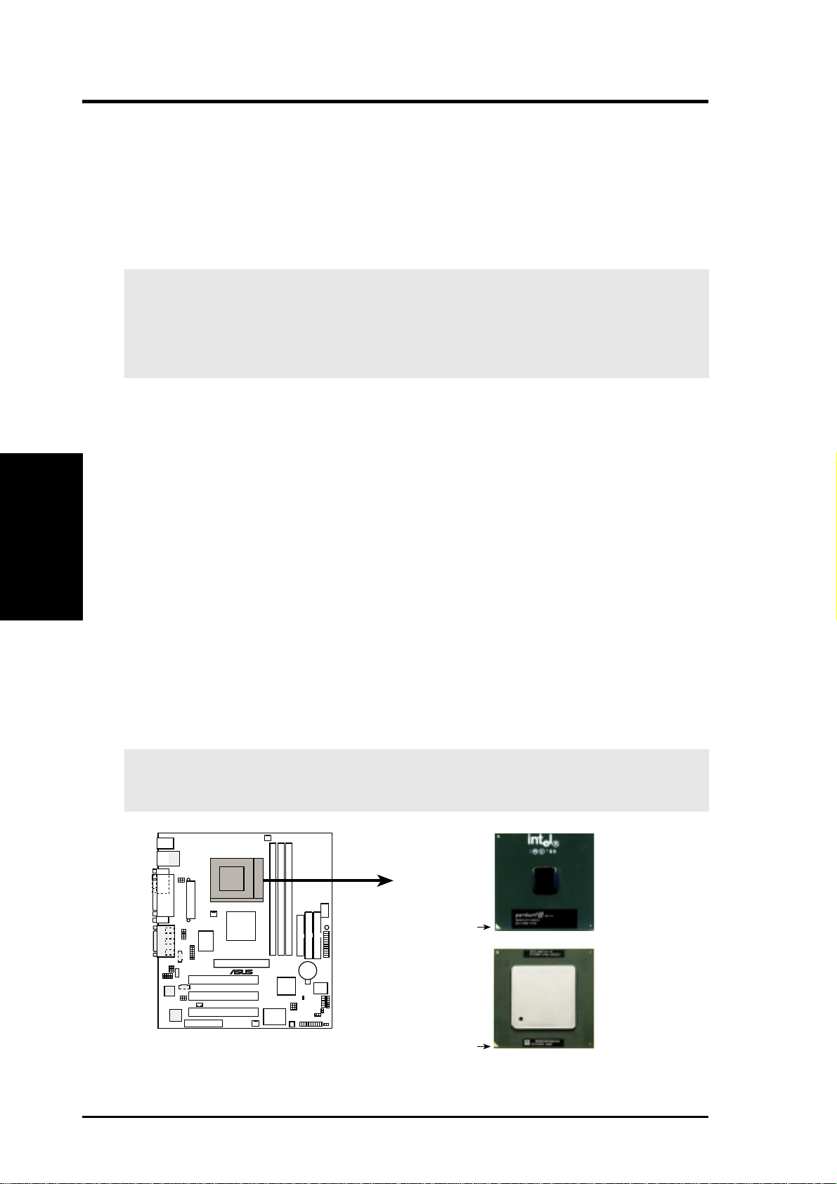
To install a CPU, first turn off your system and remove its cover. Locate the ZIF
socket and open it by first pulling the lever sideways away from the socket then
upwards to a 90-degree angle. Insert the CPU with the correct orientation as shown.
The notched corner should point towards the end of the lever . Because the CPU has
a corner pin for two of the four corners, the CPU will only fit in the orientation as
shown. The picture is for reference only; you should have a CPU fan that covers the
face of the CPU. With the added weight of the CPU fan, no force is required to
insert the CPU. Once completely inserted, close the socket’s lever while holding
down the CPU. After the CPU is , install an Intel recommended fan heatsink. Locate
the CPU fan connector (see 3.1 Motherboard Layout or 3.8 Connectors) and connect
the CPU fan cable to it.
NOTE: Do not forget to set the correct Bus Frequency and Multiple (frequency
multiple setting is available only on unlocked processors) for your Socket 370
processor or else boot-up may not be possible. Socket 370 processors provide internal
thermal sensing so that a socket mounted thermal resistor is not needed.
CAUTION! Be careful not to scrape the motherboard when mounting a clamp-
style processor fan or else damage may occur to the motherboard.
Pentium III
Celeron
(Coppermine)
FC-PGA
Gold Arrow
®
TUSL2-M
TUEP2-M Socket 370
Pentium III
(Tualatin)
FC-PGA2
Gold Arrow
26
ASUS TUEP2-M User’s Manual
3. HARDWARE SETUP
3.7 Expansion Cards
WARNING! Make sure that you unplug your power supply when adding or
removing expansion cards or other system components. Failure to do so may
cause severe damage to both your motherboard and expansion cards.
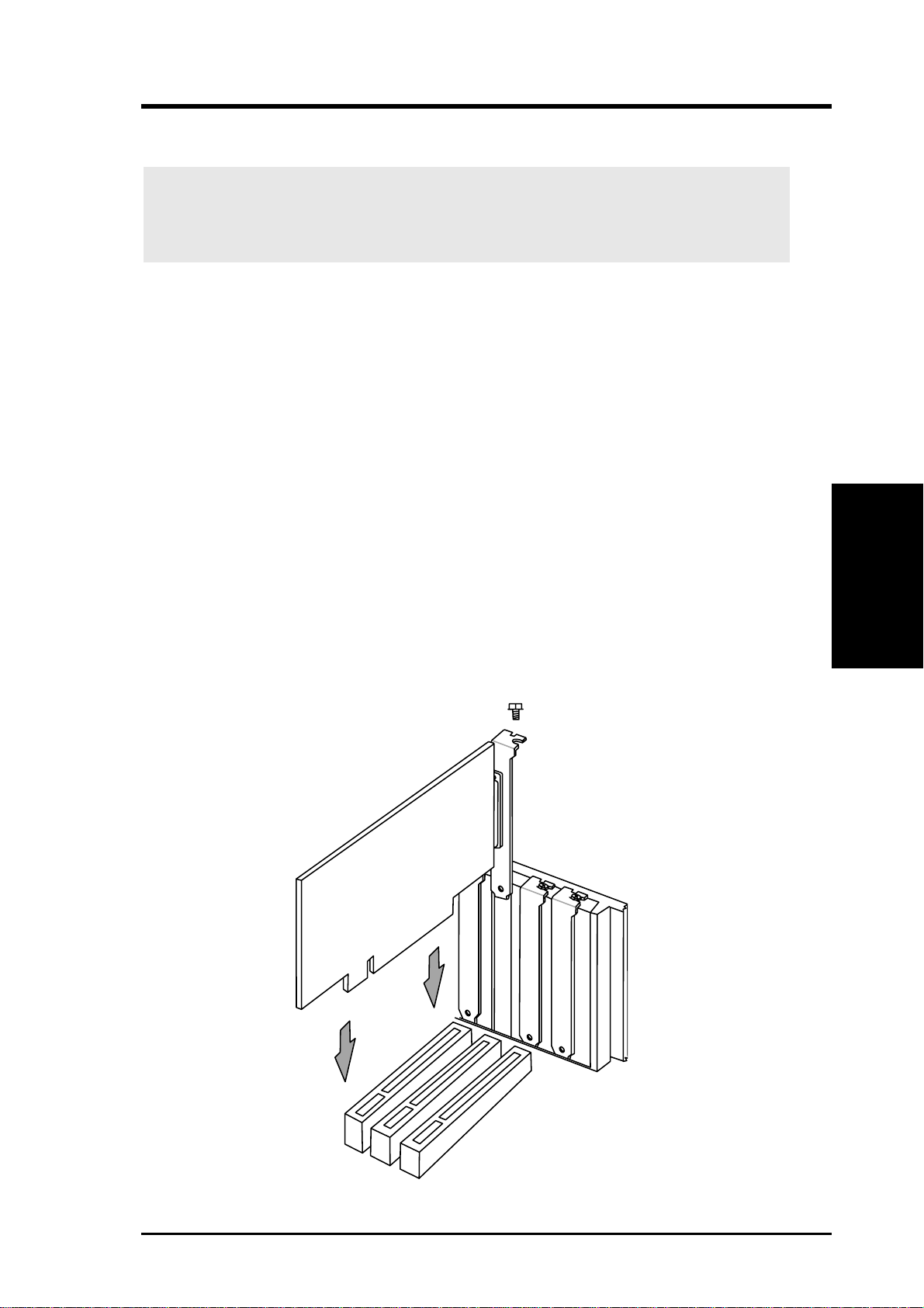
3.7.1 Expansion Card Installation Procedure
1. Read the documentation for your expansion card and make any necessary
hardware or software settings for your expansion card, such as jumpers or
switches.
2. Remove your computer system’s cover and the bracket plate with screw on the
slot you intend to use. Keep the bracket for possible future use.
3. Carefully align the card’s connectors and press firmly.
4. Secure the card on the slot with the screw you removed above.
5. Replace the computer system’s cover.
6. Set up the BIOS if necessary
(such as IRQ xx Used By ISA: Yes in PNP AND PCI SETUP)
7. Install the necessary software drivers for your expansion card.
3. H/W SETUP
Expansion Cards
ASUS TUEP2-M User’s Manual
27

3.7.2 Assigning IRQs for Expansion Cards
Some expansion cards need an IRQ to operate. Generally , an IRQ must be exclusively
assigned to one use. In a standard design, there are 16 IRQs available but most of
them are already in use, leaving 6 IRQs free for expansion cards. If your motherboard
has PCI audio onboard, an additional IRQ will be used. If your motherboard also
has MIDI enabled, another IRQ will be used, leaving 4 IRQs free.
Standard Interrupt Assignments
IRQ Priority Standard Function
0 1 System Timer
1 2 Keyboard Controller
2 N/A Programmable Interrupt
3* 11 Communications Port (COM2)
4* 12 Communications Port (COM1)
5* 13 Sound Card (sometimes LPT2)
Expansion Cards
3. H/W SETUP
6 14 Floppy Disk Controller
7* 15 Printer Port (LPT1)
8 3 System CMOS/Real Time Clock
9* 4 ACPI Mode when enabled
10* 5 IRQ Holder for PCI Steering
11* 6 IRQ Holder for PCI Steering
12* 7 PS/2 Compatible Mouse Port
13 8 Numeric Data Processor
14* 9 Primary IDE Channel
15* 10 Secondary IDE Channel
*These IRQs are usually available for ISA or PCI devices.
3. HARDWARE SETUP
Interrupt Request Table for this Motherboard
Interrupt requests are shared as shown by the following table:
ABCDEFGH
PCI slot 1 —————not shared ——
PCI slot 2 ——————not shared —
PCI slot 3 ———————shared
Onboard USB controller HC0 ———not shared ————
Onboard USB controller HC1 ———————shared
AGP shared ———————
CNR LAN ————not shared ———
CNR Audio/Modem — not shared ——————
Onboard LAN ——not shared —————
IMPORTANT: If using PCI cards on shared slots, make sure that the drivers support
“Share IRQ” or that the cards do not need IRQ assignments. Conflicts will arise
between the two PCI groups that will make the system unstable or cards inoperable.
28
ASUS TUEP2-M User’s Manual
3. HARDWARE SETUP
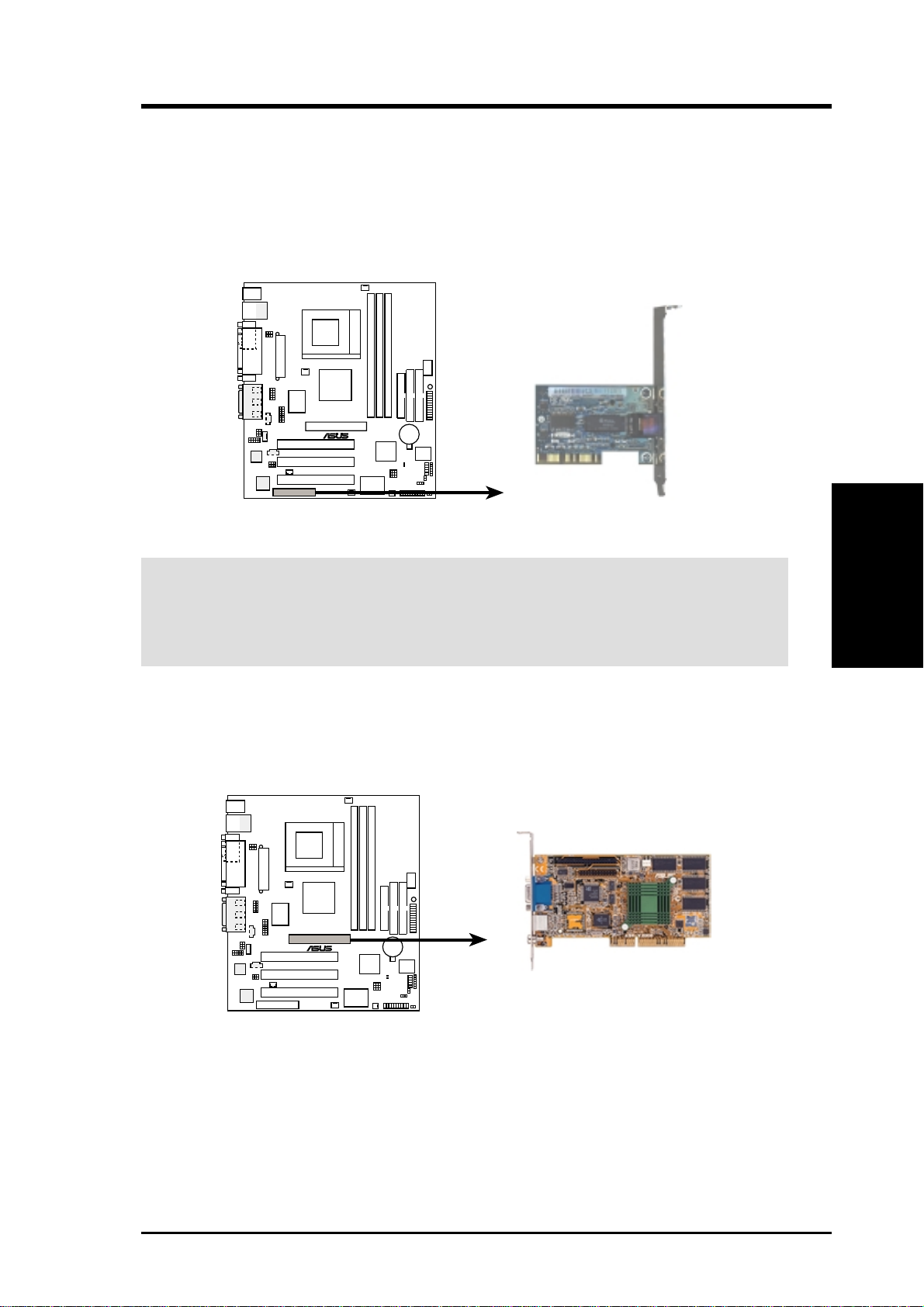
3.7.3 Communication and Networking Riser (CNR) Slot
This connector supports a specially designed network, audio, or modem riser card.
Main processing is done through software and controlled by the motherboard’s system
chipset. This provides upgradeable network, audio, and/or modem solutions at an
incredibly low cost.
NOTE: CNRs are not included with this motherboard.
®
TUEP2-M
TUEP2-M Communication
& Networking Riser Connectors
CNR Restrictions:
1. If an audio CNR card is used, it must be primary.
2. If the onboard audio CODEC is enabled, the modem CNR card must be
secondary.
3.7.4 Accelerated Graphics Port (AGP) Slot
This motherboard provides an accelerated graphics port (AGP) slot to support a new
generation of AGP graphics cards with ultra-high memory bandwidth.
®
TUEP2-M
3. H/W SETUP
Expansion Cards
TUEP2-M Accelerated Graphics Port (AGP)
ASUS TUEP2-M User’s Manual
29
3.8 Connectors
3.8.1 External Connectors
3. H/W SETUP
Connectors
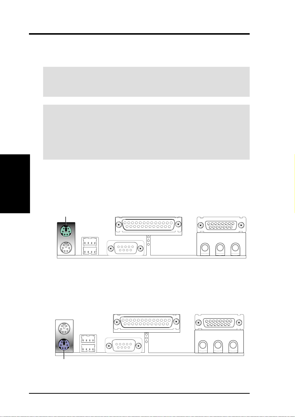
1) PS/2 Mouse Connector (Green 6-pin PS2KBMS)
3. HARDWARE SETUP
WARNING! Some pins are used for connectors or power sources. These are
clearly distinguished from jumpers in the Motherboard Layout. Placing jumper
caps over these connector pins will cause damage to your motherboard.
IMPORTANT: Ribbon cables should always be connected with the red stripe to
Pin 1 on the connectors. Pin 1 is usually on the side closest to the power connector
on hard drives and CD-ROM drives, but may be on the opposite side on floppy
disk drives. Check the connectors before installation because there may be
exceptions. IDE ribbon cable must be less than 46 cm (18 in.), with the second
drive connector no more than 15 cm (6 in.) from the first connector.
The system will direct IRQ12 to the PS/2 mouse if one is detected. If one is not
detected, expansion cards can use IRQ12. See PS/2 Mouse Function Control
in 4.4 Advanced Menu.
PS/2 Mouse (6-pin female)
2) PS/2 Keyboard Connector (Purple 6-pin PS2KBMS)
This connection is for a standard keyboard using an PS/2 plug (mini DIN). This
connector will not allow standard AT size (large DIN) keyboard plugs. You
may use a DIN to mini DIN adapter on standard AT keyboards.
PS/2 Keyboard (6-pin female)
30 ASUS TUEP2-M User’s Manual
 Loading...