

Asus TS700-X7/PS4 User Manual
TS700-X7/PS4
Pedestal/5U Rackmount Server
User Manual

E7707
First Edition
September 2012
Copyright © 2012 ASUSTeK COMPUTER INC. All Rights Reserved.
No part of this manual, including the products and software described in it, may be reproduced,
transmitted, transcribed, stored in a retrieval system, or translated into any language in any form or by any
means, except documentation kept by the purchaser for backup purposes, without the express written
permission of ASUSTeK COMPUTER INC. (“ASUS”).
Product warranty or service will not be extended if: (1) the product is repaired, modied or altered, unless
such repair, modication of alteration is authorized in writing by ASUS; or (2) the serial number of the
product is defaced or missing.
ASUS PROVIDES THIS MANUAL “AS IS” WITHOUT WARRANTY OF ANY KIND, EITHER EXPRESS
OR IMPLIED, INCLUDING BUT NOT LIMITED TO THE IMPLIED WARRANTIES OR CONDITIONS OF
MERCHANTABILITY OR FITNESS FOR A PARTICULAR PURPOSE. IN NO EVENT SHALL ASUS, ITS
DIRECTORS, OFFICERS, EMPLOYEES OR AGENTS BE LIABLE FOR ANY INDIRECT, SPECIAL,
INCIDENTAL, OR CONSEQUENTIAL DAMAGES (INCLUDING DAMAGES FOR LOSS OF PROFITS,
LOSS OF BUSINESS, LOSS OF USE OR DATA, INTERRUPTION OF BUSINESS AND THE LIKE),
EVEN IF ASUS HAS BEEN ADVISED OF THE POSSIBILITY OF SUCH DAMAGES ARISING FROM ANY
DEFECT OR ERROR IN THIS MANUAL OR PRODUCT.
SPECIFICATIONS AND INFORMATION CONTAINED IN THIS MANUAL ARE FURNISHED FOR
INFORMATIONAL USE ONLY, AND ARE SUBJECT TO CHANGE AT ANY TIME WITHOUT NOTICE,
AND SHOULD NOT BE CONSTRUED AS A COMMITMENT BY ASUS. ASUS ASSUMES NO
RESPONSIBILITY OR LIABILITY FOR ANY ERRORS OR INACCURACIES THAT MAY APPEAR IN THIS
MANUAL, INCLUDING THE PRODUCTS AND SOFTWARE DESCRIBED IN IT.
Products and corporate names appearing in this manual may or may not be registered trademarks or
copyrights of their respective companies, and are used only for identication or explanation and to the
owners’ benet, without intent to infringe.
ii

Contents
Safety information ..................................................................................................... vii
About this guide ......................................................................................................... ix
TS700-X7/PS4 specications summary ...................................................................xi
Chapter 1: Product introduction
1.1 Package contents.......................................................................................1-1
1.2 Serial number label ....................................................................................
1.3 Front panel features
1.4 Rear panel features ....................................................................................
1.5 Internal features .........................................................................................
1.6 LED information .........................................................................................
1.6.1 Front panel LEDs ........................................................................
1.6.2 Rear panel LEDs .........................................................................
Chapter 2: Hardware setup
2.1 Chassis cover ............................................................................................. 2-1
2.1.1 Removing the side cover
2.1.2 Reinstalling the side cover ..........................................................
2.2 Central Processing Unit (CPU) .................................................................
2.2.1 Installing the CPU .......................................................................
2.2.2 Installing the CPU heatsink and fan connector ...........................
2.3 System memory .........................................................................................
2.3.1 Overview .....................................................................................
2.3.2 Memory Congurations .............................................................
2.3.3 Installing a DIMM on a single clip DIMM socket
2.4 Front panel assembly ..............................................................................
2.4.1 Removing the front panel assembly ..........................................
2.4.2 Reinstalling the front panel assembly .......................................
2.5 5.25-inch drives ........................................................................................
2.6 SATA/SAS hard disk drives .....................................................................
2.6.1 Installing the HDD module cage
2.6.2 Removing the HDD module cage
2.6.3 Installing a hot-swap SATA/SAS hard disk drive .......................
2.6.4 Removing and reinstalling the backplane .................................
2.7 Expansion cards ......................................................................................
2.7.1 Installing an expansion card
2.7.2 Installing an ASUS PIKE RAID card
2.7.3 Conguring an expansion card .................................................
2.8 Cable connections ...................................................................................
................................................................................... 1-3
............................................................. 2-1
........................ 2-12
................................................ 2-15
.............................................. 2-16
...................................................... 2-20
.......................................... 2-21
1-2
1-4
1-5
1-6
1-6
1-7
2-2
2-3
2-3
2-8
2-9
2-9
2-10
2-13
2-13
2-14
2-14
2-15
2-17
2-19
2-20
2-23
2-24
iii

2.8.1 Motherboard connections..........................................................2-24
2.8.2 SATA/SAS backplane connections ..........................................
2.9 Removable components
2.9.1 System fan ................................................................................
2.9.2 Chassis footpads
2.9.3 Fan Duct
.......................................................................... 2-27
....................................................................... 2-29
.................................................................................... 2-30
2-25
2-27
Chapter 3: Installation options
3.1 Preparing the system for rack mounting ................................................. 3-1
Removing the footpads ................................................................................3-1
Removing the top cover ...............................................................................3-1
3.2 Attaching the inner rail to the server .......................................................
3.3 Attaching the rails to the rack
3.4 Mounting the server to the rack
................................................................... 3-2
................................................................ 3-3
3-2
Chapter 4: Motherboard info
4.1 Motherboard layout....................................................................................4-1
4.2 Onboard LEDs ............................................................................................
4.3 Jumpers ......................................................................................................
4.4 Internal connectors ..................................................................................
4-3
4-8
4-12
Chapter 5: BIOS setup
5.1 Managing and updating your BIOS ..........................................................5-1
5.1.1 ASUS CrashFree BIOS 3 ............................................................
5.1.2 ASUS EZ Flash 2 ........................................................................
5.1.3 BUPDATER .................................................................................
5.2 BIOS setup program ..................................................................................
5.2.1 BIOS menu screen ......................................................................
5.2.2 Menu bar .....................................................................................
5.2.3 Menu items
5.2.4 Submenu items ...........................................................................
5.2.5 Navigation keys ...........................................................................
5.2.6 General help
5.2.7 Conguration elds .....................................................................
5.2.8 Pop-up window
5.2.9 Scroll bar .....................................................................................
5.3 Main menu ..................................................................................................
5.3.1 System Date
5.3.2 System Time ..............................................................................
5.4 Advanced menu .........................................................................................
.................................................................................. 5-7
................................................................................ 5-7
............................................................................ 5-7
............................................................................... 5-8
5-1
5-2
5-3
5-5
5-6
5-6
5-7
5-7
5-7
5-7
5-8
5-8
5-9
iv

5.4.1 CPU Conguration ...................................................................... 5-9
5.4.2 CPU Power Management Conguration ...................................
5.4.3 Chipset Conguration
5.4.4 PCH SATA Conguration ..........................................................
5.4.5 PCI Subsystem Settings ...........................................................
5.4.6 USB Conguration ....................................................................
5.4.7 Trusted Computing ....................................................................
5.4.8 ACPI Settings ............................................................................
5.4.9 WHEA Conguration .................................................................
5.4.10 APM setting ...............................................................................
5.4.11 Serial Port Console Redirection ................................................
5.4.12 Onboard LAN Conguration ......................................................
5.4.13 ME Subsystem ..........................................................................
5.4.14 Onboard Devices Conguration ................................................
5.4.15 Runtime Error Logging ..............................................................
5.5 Server Mgmt menu ...................................................................................
5.5.1 System Event Log .....................................................................
5.5.2 BMC network conguration .......................................................
5.6 Event Logs menu .....................................................................................
5.6.1 Change Smbios Event Log Settings .........................................
5.7 Boot menu ................................................................................................
5.7.1 CSM parameters .......................................................................
5.8 Monitor menu ...........................................................................................
5.9 Security menu ..........................................................................................
5.10 Tool menu .................................................................................................
5.11 Exit menu ..................................................................................................
................................................................ 5-13
5-11
5-19
5-20
5-23
5-25
5-25
5-26
5-26
5-27
5-30
5-31
5-31
5-32
5-33
5-34
5-35
5-36
5-36
5-38
5-40
5-41
5-42
5-44
5-44
Chapter 6: RAID conguration
6.1 Setting up RAID .......................................................................................... 6-1
6.1.1 RAID denitions ..........................................................................
6.1.2 Installing hard disk drives ............................................................
6.1.3 Setting the RAID item in BIOS ....................................................
6.1.4 RAID conguration utilities ..........................................................
6.2 LSI Software RAID Conguration Utility .................................................
6.2.1 Creating a RAID set ....................................................................
6.2.2 Adding or viewing a RAID conguration
6.2.3 Initializing the virtual drives .......................................................
6.2.4 Rebuilding failed drives .............................................................
6.2.5 Checking the drives for data consistency
6.2.6 Deleting a RAID conguration ...................................................
.................................... 6-10
.................................. 6-17
6-1
6-2
6-2
6-2
6-3
6-4
6-11
6-15
6-20
v

6.2.7 Selecting the boot drive from a RAID set .................................. 6-21
6.2.8 Enabling WriteCache ................................................................
6.3 Intel
®
Rapid Storage Technology enterprise SATA Option
ROM Utility ................................................................................................
6.3.1 Creating a RAID set ..................................................................
6.3.2 Creating a Recovery set
6.3.3 Deleting a RAID set
............................................................ 6-26
................................................................... 6-28
6.3.4 Resetting disks to Non-RAID ....................................................
6.3.5 Exiting the Intel
6.3.6 Rebuilding the RAID
®
Rapid Storage Technology utility ....................6-30
.................................................................. 6-30
6.3.7 Setting the Boot array in the BIOS Setup Utility ........................
6.4 Intel
®
Rapid Storage Technology enterprise Utility (Windows) ...........6-33
6.4.1 Creating a RAID set ..................................................................
6.4.2 Changing a Volume Type ..........................................................
6.4.3 Deleting a volume .....................................................................
6.4.4 Preferences ...............................................................................
6-22
6-23
6-25
6-29
6-32
6-34
6-36
6-37
6-38
Chapter 7: Driver installation
7.1 RAID driver installation .............................................................................7-1
7.1.1 Creating a RAID driver disk
7.1.2 Installing the RAID controller driver
7.2 Intel
7.3 Intel
®
chipset device software installation .............................................7-14
@
Network Connections Software installation ...............................7-17
7.4 VGA driver installation ............................................................................
7.5 Intel
7.6 Intel
®
C600 MEI NULL HECI Driver ..........................................................7-22
®
Rapid Storage Technology enterprise 3.1 installation ............... 7-23
7.7 Asmedia ASM104x USB 3.0 Host Controller Driver installation ..........
7.8 Intel
®
WG82574L Gigabit Adapters Driver installation .......................... 7-29
7.9 Management applications and utilities installation ..............................
7.9.1 Running the support DVD .........................................................
7.9.2 Drivers menu .............................................................................
7.9.3 Utilities menu
............................................................................. 7-34
7.9.4 Make disk menu ........................................................................
7.9.5 Contact information ...................................................................
......................................................... 7-1
............................................. 7-4
7-20
7-26
7-33
7-33
7-33
7-34
7-34
Appendices
Notices .................................................................................................................... A-1
ASUS contact information ...................................................................................... A-3
vi
Safety information
Electrical safety
To prevent electrical shock hazard, disconnect the power cable from the
•
electrical outlet before relocating the system.
When adding or removing devices to or from the system, ensure that the power
•
cables for the devices are unplugged before the signal cables are connected. If
possible, disconnect all power cables from the existing system before you add
a device.
Before connecting or removing signal cables from the motherboard, ensure
•
that all power cables are unplugged.
Seek professional assistance before using an adapter or extension cord.
•
These devices could interrupt the grounding circuit.
Ensure that your power supply is set to the correct voltage in your area. If you
•
are not sure about the voltage of the electrical outlet you are using, contact
your local power company.
If the power supply is broken, do not try to x it by yourself. Contact a qualied
•
service technician or your retailer.
Operation safety
Before installing the motherboard and adding devices on it, carefully read all
•
the manuals that came with the package.
Before using the product, ensure all cables are correctly connected and the
•
power cables are not damaged. If you detect any damage, contact your dealer
immediately.
To avoid short circuits, keep paper clips, screws, and staples away from
•
connectors, slots, sockets and circuitry.
Avoid dust, humidity, and temperature extremes. Do not place the product in
•
any area where it may become wet.
Place the product on a stable surface.
•
If you encounter technical problems with the product, contact a qualied
•
service technician or your retailer.
This product is equipped with a three-wire power cable and plug for the user’s
safety. Use the power cable with a properly grounded electrical outlet to avoid
electrical shock.
vii
Lithium-Ion Battery Warning
CAUTION! Danger of explosion if battery is incorrectly replaced. Replace
only with the same or equivalent type recommended by the manufacturer.
Dispose of used batteries according to the manufacturer’s instructions.
CD-ROM Drive Safety Warning
CLASS 1 LASER PRODUCT
Heavy System
CAUTION! This server system is heavy. Ask for assistance when moving or
carrying the system.
viii

About this guide
This user guide contains the information you need when installing and conguring
the motherboard.
How this guide is organized
1. Chapter 1: Product introduction
This chapter describes the general features of the server, including sections
on front panel and rear panel specications.
2. Chapter 2: Hardware setup
This chapter lists the hardware setup procedures that you have to perform
when installing or removing system components.
3. Chapter 3: Installation options
This chapter describes how to install optional components into the barebone
server.
4. Chapter 4: Motherboard information
This chapter gives information about the motherboard that comes with the
server. This chapter includes the motherboard layout, jumper settings, and
connector locations.
5. Chapter 5: BIOS information
This chapter tells how to change system settings through the BIOS Setup
menus and describes the BIOS parameters.
6. Chapter 6: RAID conguration
This chapter tells how to change system settings through the BIOS Setup
menus. Detailed descriptions of the BIOS parameters are also provided.
7. Chapter 7: Driver installation
This chapter provides instructions for installing the necessary drivers for
different system components.
Where to nd more information
Refer to the following sources for additional information and for product and
software updates.
1. ASUS Server Web-based Management (ASWM) user guide
This manual tells how to set up and use the proprietary ASUS server
management utility.
2. ASUS websites
The ASUS websites worldwide provide updated information for all ASUS
hardware and software products. Refer to the ASUS contact information.
ix
Conventions used in this guide
To ensure that you perform certain tasks properly, take note of the following
symbols used throughout this manual.
DANGER/WARNING: Information to prevent injury to yourself when trying
to complete a task.
CAUTION: Information to prevent damage to the components when trying
to complete a task.
IMPORTANT: Instructions that you MUST follow to complete a task.
NOTE: Tips and additional information to help you complete a task.
Typography
Bold text Indicates a menu or an item to select.
Italics
<Key> Keys enclosed in the less-than and greater-than sign
<Key1> + <Key2> + <Key3> If you must press two or more keys simultaneously, the key
Used to emphasize a word or a phrase.
means that you must press the enclosed key.
Example: <Enter> means that you must press the Enter or
Return key.
names are linked with a plus sign (+).
x
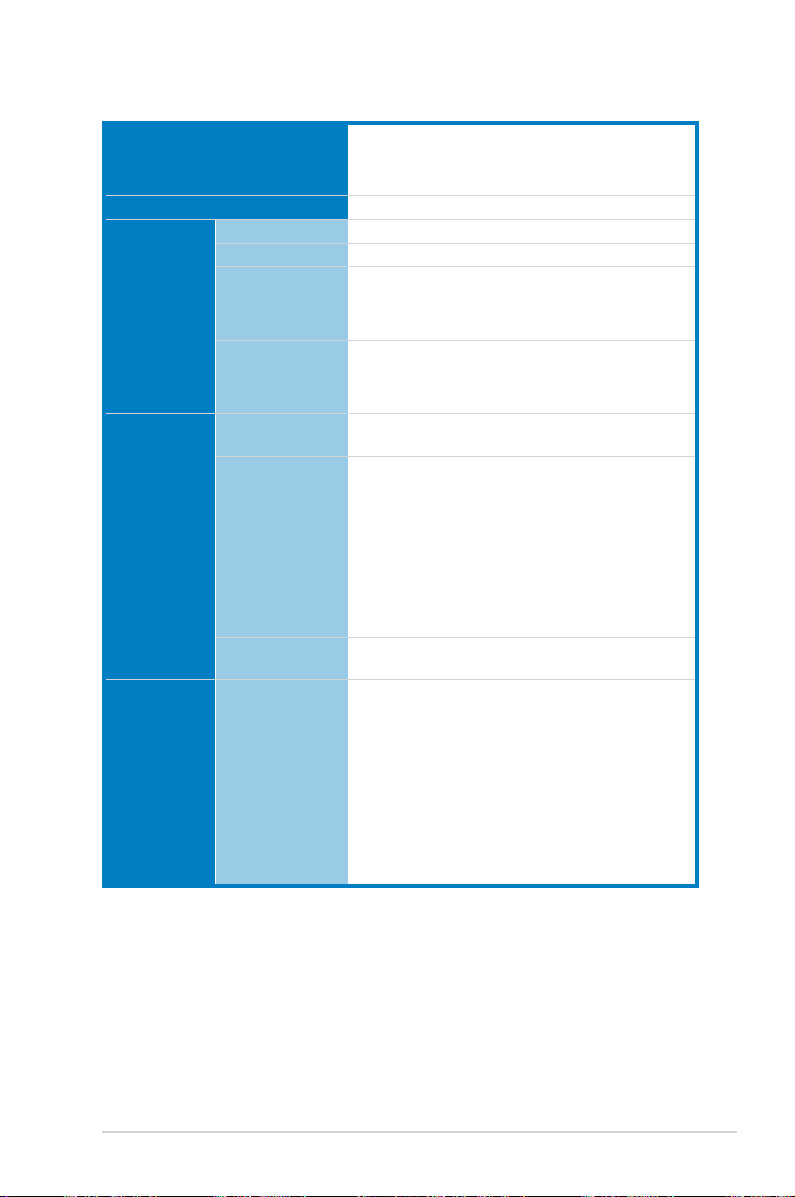
TS700-X7/PS4 specications summary
CPU
Chipset
Memory Total Slots
Capacity
Memory Type
Memory Size
Expansion
Slots
Storage SATA
Total PCI/PCIX/PCI-E Slots
Slot Type
Additional
Slot
Controller
2 x LGA2011 socket for Intel® Xeon®
E5-2600 Series processors
QPI 6.4 / 7.2 / 8.0 GT/s
Intel® C602-A
8 (4-channel per CPU, 4 DIMMs per CPU)
Maximum up to 256GB (RDIMM)
DDR3 800/1066/1333/1600 RDIMM
DDR3 1066/1333/1600 UDIMM (ECC/non-ECC)
DDR3 1066/1333 LR-DIMM
2GB, 4GB, 8GB, 16GB, 32GB* (RDIMM)
2GB, 4GB, 8GB* (UDIMM)
8GB, 16GB, 32GB* (LRDIMM)
5
- Slot 1: PCI-E x8 (x8 Gen3 Link), MIO-892
supported
- Slot 2: PCI-E x16 (x16 Gen3 Link; Audio
switches to x8 Link if PCIE3 is occupied)
- Slot 3: PCI-E x8 (x8 Gen3 Link)
- Slot 4: PCI-E x16 (x16 Gen3 Link; Audio
switches to x8 Link if PCIE1 is occupied)
- Slot 5: PCI-E x8 (x4 Gen2 Link)
1 x PIKE slot for Storage Enhancement
Intel® C602-A:
<AHCI>
2 SATA 6Gb/s ports
4 SATA 3Gb/s ports
Intel® RSTe (for Windows only)
(Support software RAID 0, 1, 10 & 5)
LSI® MegaRAID (for Linux/Windows)
(Support software RAID 0, 1, 10)
(continued on the next page)
xi
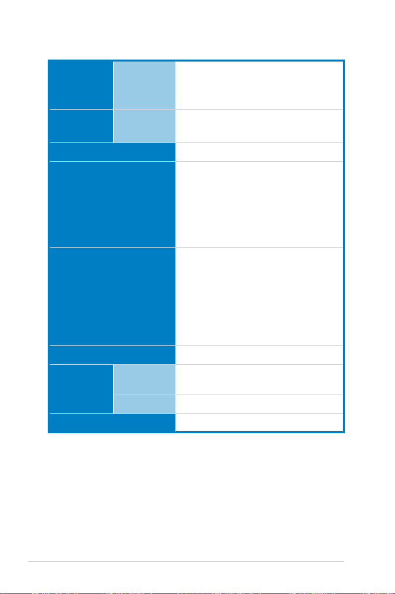
TS700-X7/PS4 specications summary
Storage
SAS
Controller
Optional:
ASUS PIKE 2008 8-port SAS 6G RAID card
ASUS PIKE 2008/IMR 8-port SAS 6G RAID card
ASUS PIKE 2108 8-port SAS 6G HW RAID card
HDD Bays I = internal
4 x Hot-swap 3.5” HDD Bays
A or S = hotswappable
VGA Aspeed AST2300 16MB
Onboard I/O
1 x External Serial Port
1 x Internal Serial Port
3 x RJ-45 ports (One for ASMB6-iKVM)
4 x USB 2.0 ports (Front * 2, Rear * 2)
2 x USB 3.0 ports (Rear)
1 x VGA port
1 x PS/2 keyboard/mouse port
OS Support
Windows® Server 2012 64-bit
Windows® 8 64-bit
Windows® Server 2008 Enterprise SP2 64-bit
Windows® Server 2008 Enterprise R2 SP1 64-bit
RedHat® Enterprise Linux AS 5.8/6.3 64-bit
SuSE® Linux Enterprise Server 11.2 SP2 64-bit
CentOS 5.8/6.2 64-bit
(Note: Subject to change without prior notice.)
Anti-virus Software Optional anti-virus CD Pack
Management
Solution
Out of Band
Remote
Default 1 x ASMB6-iKVM for KVM-over-Internet
Management
Software
ASWM Enterprise 2.0
Dimension (HH x WW x DD) 445mm x 217.5mm x 545mm
(continued on the next page)
xii
®
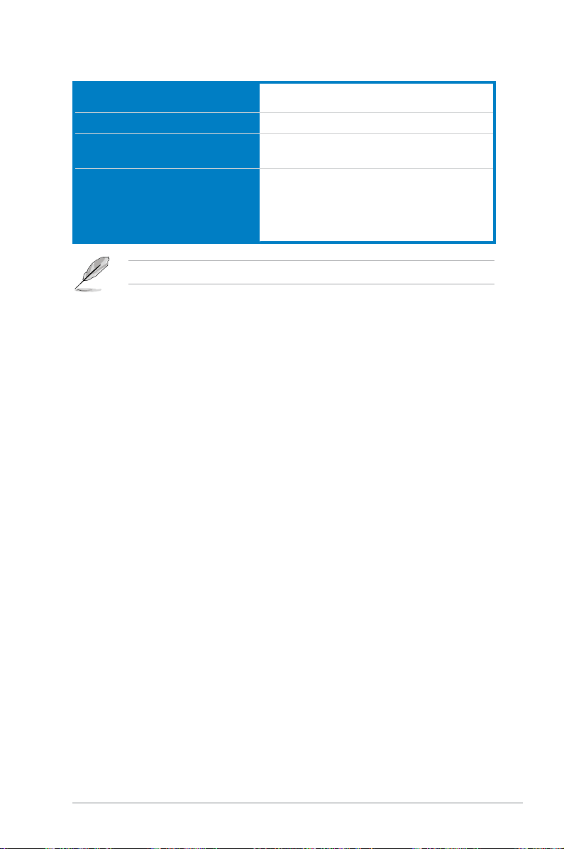
TS700-X7/PS4 specications summary
Net Weight Kg (CPU, DRAM &
HDD not included)
Power Supply
Power Supply Rating Output
Environment
Specications are subject to change without notice.
17 Kg
500W 80PLUS Bronze Single Power Supply
500W: 100-240 Vac,
10 - 6A, 50-60 Hz, Class 1
Operating temperature: 10℃ ~ 35℃
Non operating temperature: -40℃ ~ 70℃
Non operating humidity: 20% ~ 90%
(Non condensing)
xiii

xiv
Product introduction
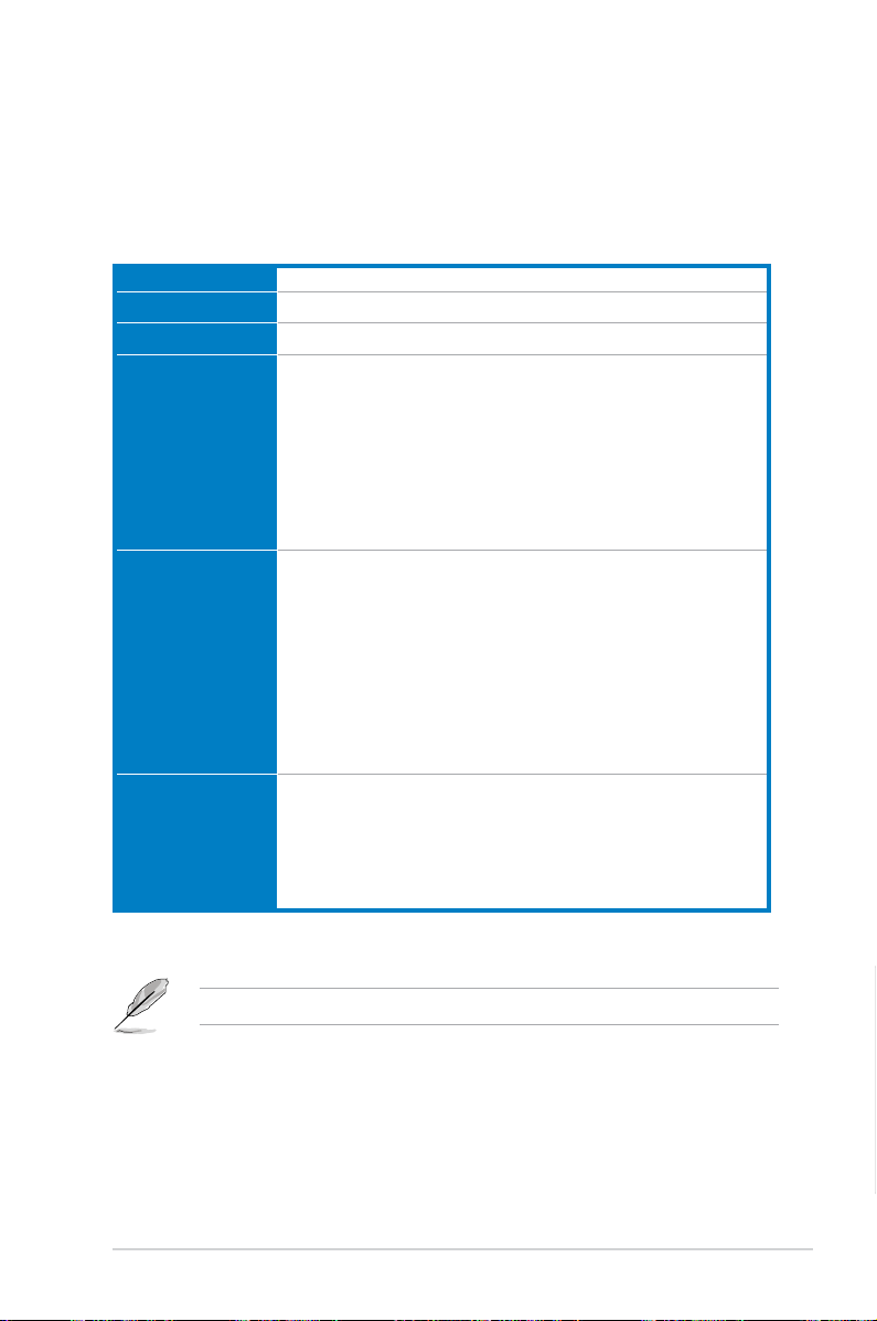
1.1 Package contents
Model Name TS700-X7/PS4
Chassis ASUS T50A Pedestal 5U Rackmount Chassis
Motherboard ASUS Z9PA-D8 Server Board
Component 1 x 500W 80PLUS Bronze Single Power Supply
4 x hot-swap HDD trays
1 x SAS/SATA2 Backplane with four data cables
1 x Front I/O Board
4 x System Fans
• 3 x Front (80mm x 38mm) system fans
• 1 x Rear (120mm x 38mm) system fan
Accessories 1 x TS700-X7/PS4 User’s Guide
1 x ASUS ASWM Enterprise User’s Guide
1 x TS700-X7/PS4 Support CD (including ASWM*)
1 x Bag of screws
1 x ASMB6 Series DVD
1 x ASUS ASWM Enterprise* User’s Guide
1 x ASMB6 User’s Guide
1 x AC Power Cable
Optional Items 2 x CPU Heatsinks
DVD-ROM / DVD-RW
ASUS TS700-X7/PS4 Rackmount Rail Kit
ASUS PIKE RAID Card
1
*ASUS System Web-based Management
If any of the above items is damaged or missing, contact your retailer.
TS700-X7/PS4
Chapter 1
1-1
1.2 Serial number label
For faster and quicker troubleshooting solutions from the ASUS Technical Support
team, provide the product’s serial number containing 12 characters such as
xxS0xxxxxxxx as shown in the gure below.
TS700-X7/PS4
xxS0xxxxxxxx
Chapter 1
1-2
Chapter 1: Product introduction
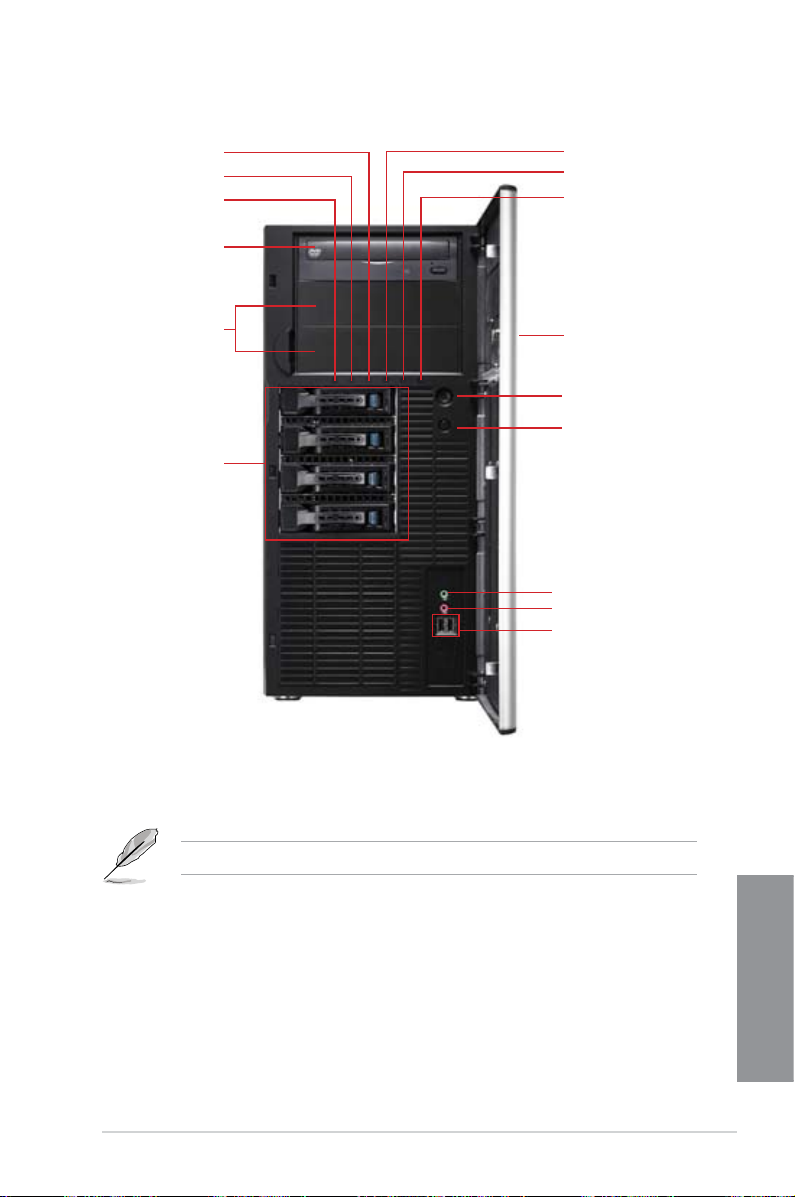
1.3 Front panel features
Message LED
HDD access LED
Power LED
Optical drive
Empty 5.25-inch
bays
4-bay HDD cage
LAN1 LED
LAN2 LED
Locate LED
(Reserved)
Security lock
Power button
Reset button
Headphone
output jack*
Microphone jack
USB 2.0 ports
*The audio jacks function only with an optional MIO audio card.
Refer to section 1.6.1 Front panel LEDs for the LED descriptions.
TS700-X7/PS4
Chapter 1
1-3
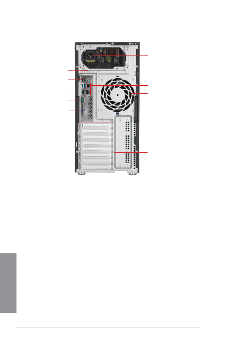
1.4 Rear panel features
Power connector
PS/2 mouse/keyboard port
USB 2.0 ports
USB 3.0 ports
Gigabit LAN ports
COM port
VGA port
*This port is for the ASUS ASMB6-iKVM controller card only.
Chassis lock
LAN port*
120mm x 38mm
system fan
Chassis intrusion switch
Expansion slots
Chapter 1
1-4
Chapter 1: Product introduction
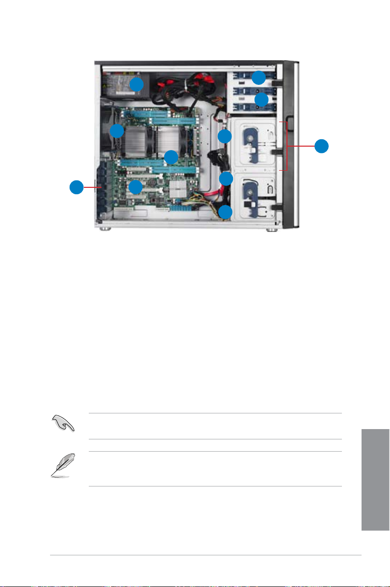
1.5 Internal features
1
2
9
3
11
4
5
10
1. 500W Power Supply
2. 120mm x 38mm system fan
3. ASUS Z9PA-D8 Server Board
4. Chassis intrusion switch
5. Expansion card locks
6. Optical drive
7. 2 x 5.25-inch drive bays
8. 4-bay HDD module (rst set)
9. SATA/SAS backplane board (rst set, hidden)
10. 80mm x 38mm system fans
6
7
8
Turn off the system power and detach the power supply before removing or
replacing any system component.
The barebone server does not include a oppy disk drive and an optical disc
drive. Connect a USB oppy disk drive or a USB ODD to any of the USB ports
on the front or rear panel if you need to use a oppy disk or a optical disc.
TS700-X7/PS4
Chapter 1
1-5
1.6 LED information
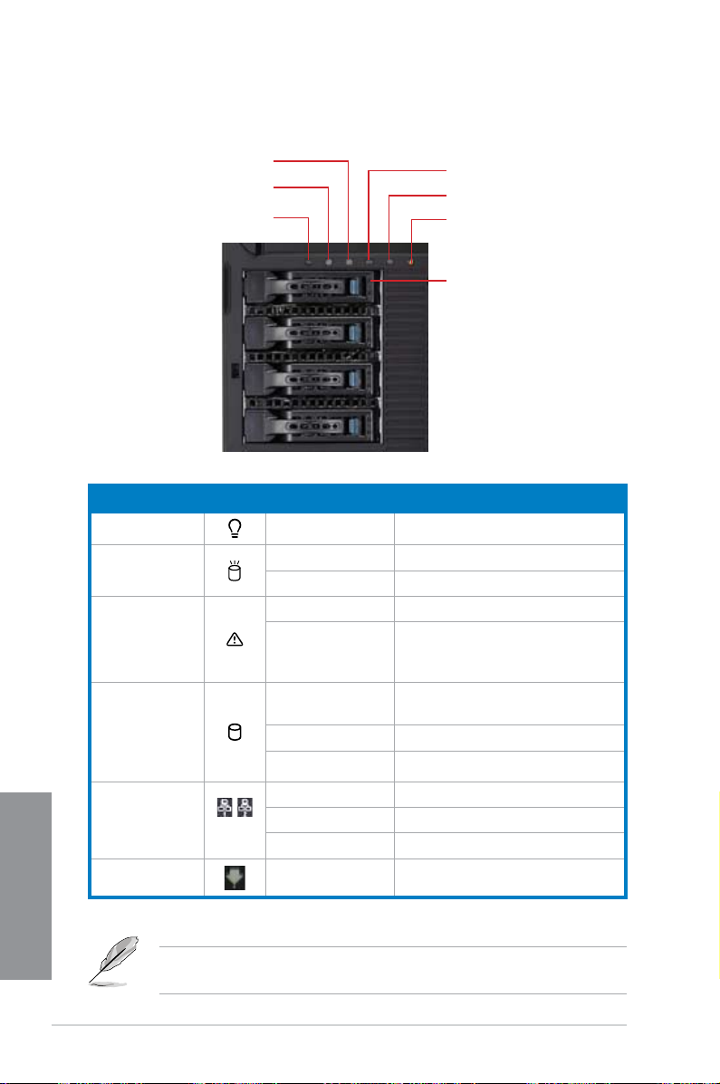
1.6.1 Front panel LEDs
Message LED
HDD Access LED
Power LED
LED Icon Display status Description
Power LED ON System power ON
HDD Access
LED
Message LED OFF System is normal; no incoming event
Drive status LED Green Bridge board connected to backplane
OFF No activity
Blinking Read/write data into the HDD.
Lighting up A hardware temperature overheat is
Red HDD failure
Green/Red Blinking HDD rebuilding using the RAID card
LAN1 LED
LAN2 LED
Locate LED (Reserved)
Drive Status LED
detected. Use ASWM to check the
abnormal status.
Installed HDD is in good condition
LAN LEDs
Chapter 1
Locate LED ON Locates a specic server
1-6
OFF
Blinking LAN accessing
ON
The Power, HDD Access, LAN and Message LEDs are visible even if the
system front bezel is closed.
Chapter 1: Product introduction
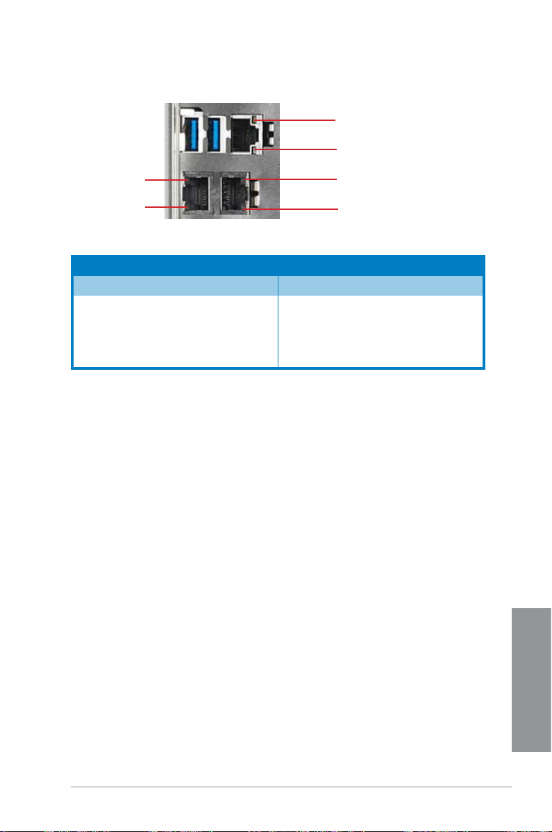
1.6.2 Rear panel LEDs
ACT/LINK LED
SPEED LED
ACT/LINK LED
SPEED LED
ACT/LINK LED SPEED LED
Status Description Status Description
OFF No link OFF 10 Mbps connection
GREEN Linked ORANGE
BLINKING Data activity GREEN 1 Gbps connection
ACT/LINK LED
SPEED LED
100 Mbps
connection
TS700-X7/PS4
Chapter 1
1-7
Chapter 1
1-8
Chapter 1: Product introduction
Hardware setup
2.1 Chassis cover
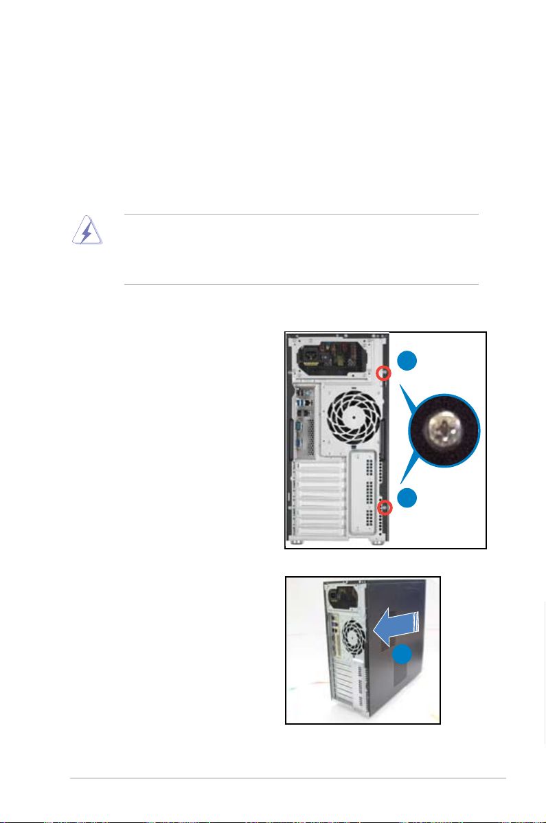
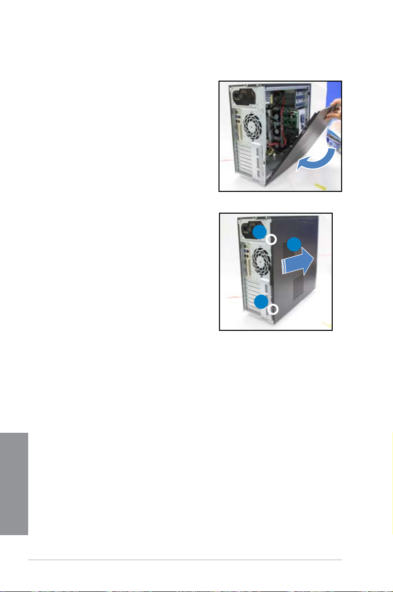
2.1.1 Removing the side cover
Ensure that you unplug the power cord before removing the side cover.
•
Take extra care when removing the side cover. Keep your ngers from
•
components inside the chassis that can cause injury, such as the CPU fan,
rear fan, and other sharp-edged parts.
To remove the side cover:
1. Remove the two screws that secure
the side cover.
2
1
2. Slide the side cover for about half
an inch toward the rear until it is
disengaged from the chasssis.
3. Carefully lift the side cover and set it
aside.
TS700-X7/PS4
1
2
Chapter 2
2-1
2.1.2 Reinstalling the side cover
To reinstall the side cover:
1. Match and insert the lower sliding edge
of the side cover to the corresponding
chassis edge.
2. Slide the side cover toward the front
panel until it snaps in place.
3. Drive in the two screws you
removed earlier to secure the side
cover.
1
3
2
3
Chapter 2
2-2
Chapter 2: Hardware setup
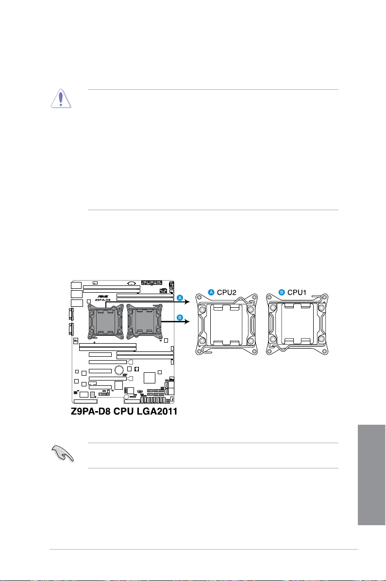
2.2 Central Processing Unit (CPU)
The motherboard comes with a surface mount LGA2011 socket designed for the
Intel® Xeon E5-2600 family processor.
Upon purchase of the motherboard, ensure that the PnP cap is on
•
the socket and the socket contacts are not bent. Contact your retailer
immediately if the PnP cap is missing, or if you see any damage to the PnP
cap/socket contacts/motherboard components. ASUS shoulders the repair
cost only if the damage is shipment/transit-related.
Keep the cap after installing the motherboard. ASUS will process Return
•
Merchandise Authorization (RMA) requests only if the motherboard comes
with the cap on the LGA 2011 Socket.
The product warranty does not cover damage to the socket contacts
•
resulting from incorrect CPU installation/removal, or misplacement/loss/
incorrect removal of the PnP cap.
2.2.1 Installing the CPU
To install a CPU:
1. Locate the CPU socket on the motherboard.
Before installing the CPU, ensure that the socket box is facing towards you and
the load lever is on your left.
TS700-X7/PS4
Chapter 2
2-3
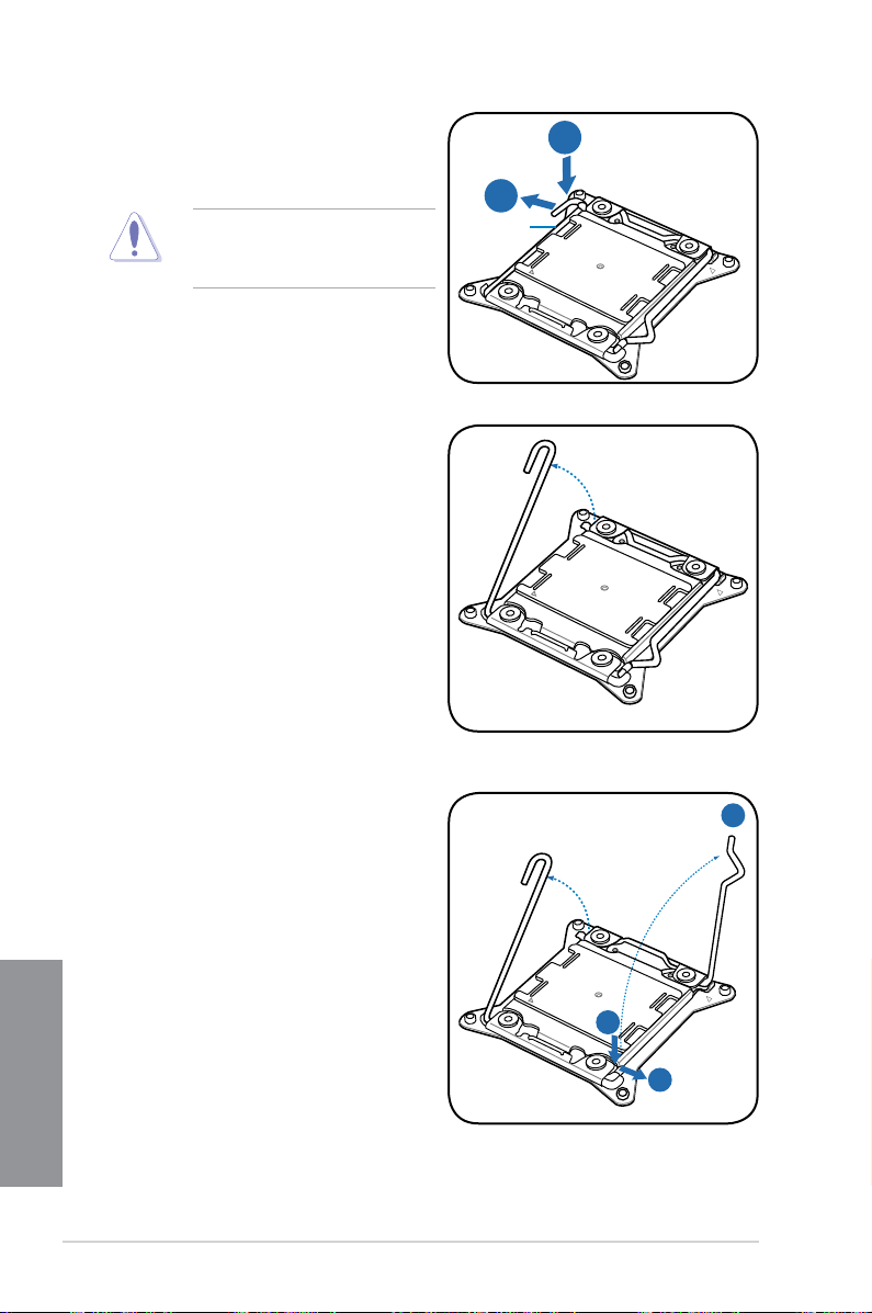
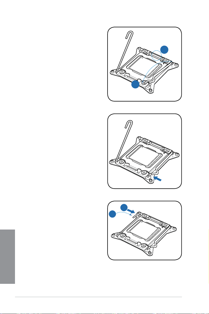
2. Press the left load lever with your
B
A
E
D
C
thumb (A), then move it to the left
(B) until it is released from the
retention tab.
To prevent damage to the socket
pins, do not remove the PnP cap
unless you are installing a CPU.
3. Slightly lift the load lever in the
direction of the arrow.
Load lever
4. Press the right load lever with your
thumb (C), then move it to the right
(D) until it is released from the
retention tab. Lift the load lever in
the direction of the arrow (E).
Chapter 2
2-4
Chapter 2: Hardware setup
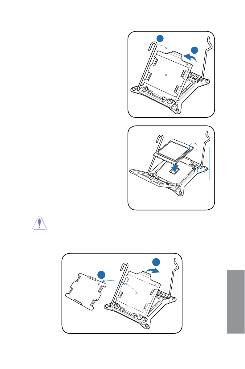
I
H
G
F
5. Push the left load lever (F) to lift the
load plate (G).
6. Position the CPU over the socket,
ensuring that the triangle mark is on
the top-right corner of the socket.
Triangle
mark
The CPU ts in only one correct orientation. DO NOT force the CPU into the
socket to prevent bending the connectors on the socket and damaging the CPU!
7. Remove the PnP cap (H) from the CPU socket and close the load plate (I).
TS700-X7/PS4
Chapter 2
2-5
K
J
8. Push down the right load lever (J),
M
L
ensuring that the edge of the load
plate is xed by the lever (K).
9. Insert the right load lever under the
retention tab.
10. Push down the left load lever (L),
Chapter 2
2-6
and then insert the lever under the
retention tab (M).
Chapter 2: Hardware setup
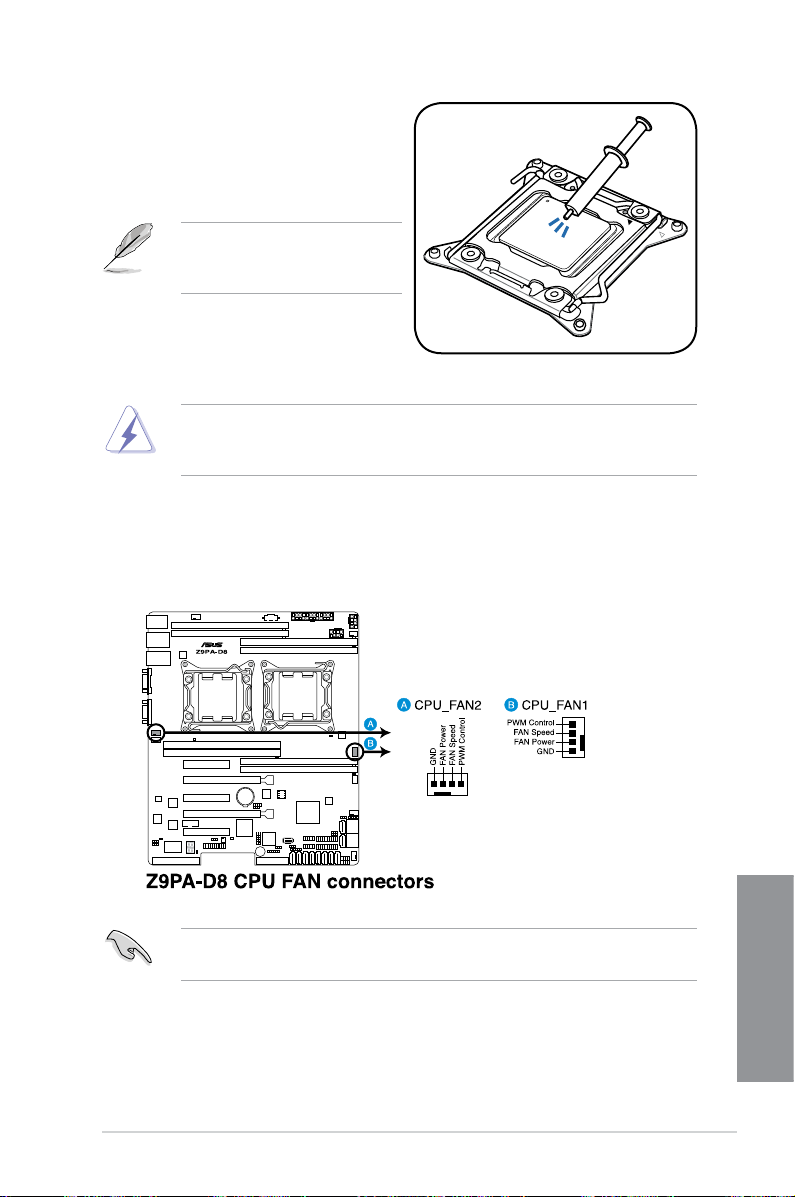
11. Apply some Thermal Interface
Material to the exposed area of
the CPU that the heatsink will be
in contact with, ensuring that it is
spread in an even thin layer.
Some heatsinks come with preapplied thermal paste. If so, skip
this step.
The Thermal Interface Material is toxic and inedible. DO NOT eat it. If it gets into
your eyes or touches your skin, wash it off immediately, and seek professional
medical help if irritation occurs.
12. Install a compatible CPU heatsink and fan.
13. Connect the CPU fan cable to the connector on the motherboard labeled
CPU_FAN1 / CPU_FAN2.
DO NOT forget to connect the CPU fan connector! Hardware monitoring errors
can occur if you fail to plug this connector.
TS700-X7/PS4
Chapter 2
2-7
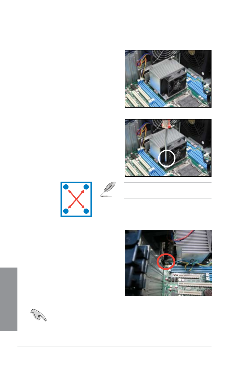
2.2.2 Installing the CPU heatsink and fan
To install the CPU heatsink and fan:
1. Place the CPU heatsink and fan on
top of the installed CPU, ensuring
that the four screws match the holes
on the support plate, and the arrow
on the fan faces the rear panel of
the server chassis.
2. Twist each of the four screws with
a Philips (cross) screwdriver just
enough to attach the CPU heatsink
and fan to the motherboard. When
the four screws are attached,
tighten them one by one to
completely secure the CPU heatsink
and fan.
3. Connect the CPU heatsink and
fan cable to the connector on the
motherboard.
Chapter 2
2-8
A
B
Do not forget to connect the CPU heatsink and fan connector. Hardware
monitoring errors can occur if you fail to plug this connector.
B
A
Tighten the four heatsink screws in a
diagonal sequence.
Chapter 2: Hardware setup
 Loading...