

Page 1
TS700-E6/RS8
Pedestal/5U Rackmount Server
User Guide
Page 2

E4717
First Edition
May 2009
Copyright © 2009 ASUSTeK COMPUTER INC. All Rights Reserved.
No part of this manual, including the products and software described in it, may be reproduced, transmitted,
transcribed, stored in a retrieval system, or translated into any language in any form or by any means,
except documentation kept by the purchaser for backup purposes, without the express written permission
of ASUSTeK COMPUTER INC. (“ASUS”).
ASUS provides this manual “as is” without warranty of any kind, either express or implied, including but not
limited to the implied warranties or conditions of merchantability or tness for a particular purpose. In no
event shall ASUS, its directors, ofcers, employees, or agents be liable for any indirect, special, incidental,
or consequential damages (including damages for loss of prots, loss of business, loss of use or data,
interruption of business and the like), even if ASUS has been advised of the possibility of such damages
arising from any defect or error in this manual or product.
Specications and information contained in this manual ae furnished for informational use only, and are
subject to change at any time without notice, and should not be construed as a commitment by ASUS.
ASUS assumes no responsibility or liability for any errors or inaccuracies that may appear in this manual,
including the products and software described in it.
Product warranty or service will not be extended if: (1) the product is repaired, modied or altered, unless
such repair, modication of alteration is authorized in writing by ASUS; or (2) the serial number of the
product is defaced or missing.
Products and corporate names appearing in this manual may or may not be registered trademarks or
copyrights of their respective companies, and are used only for identication or explanation and to the
owners’ benet, without intent to infringe.
ii
Page 3

Contents
Contents ...................................................................................................... iii
Notices ........................................................................................................ vii
Safety information .................................................................................... viii
About this guide ......................................................................................... ix
Chapter 1: Product introduction
1.1 System package contents ........................................................... 1-2
1.2 Serial number label ......................................................................
1.3 Systemspecications .................................................................
1.4 Front panel features .....................................................................
1.5 Rear panel features ......................................................................
1.6 Internal features ...........................................................................
1.7 LED information ...........................................................................
1.7.1 Front panel LEDs ............................................................
1.7.2 Rear panel LEDs .............................................................
Chapter 2: Hardware setup
2.1 Chassis cover ............................................................................... 2-2
2.1.1 Removing the side cover ................................................
2.1.2 Reinstalling the side cover ..............................................
2.2 Central Processing Unit (CPU) ...................................................
2.2.1 Installing the CPU ...........................................................
2.2.2 Installing the CPU heatsink and fan ................................
2.3 System memory ...........................................................................
2.3.1 Overview .........................................................................
2.3.2 Memory Congurations ...................................................
2.3.3 Installing a DIMM ..........................................................
2.3.4 Removing a DIMM ........................................................
2.4 Front panel assembly ................................................................
2.4.1 Removing the front panel assembly ...............................
2.4.2 Reinstalling the front panel assembly ............................
2.5 5.25-inch drives ..........................................................................
2.6 SATA/SAS hard disk drives .......................................................
2.6.1 Installing the HDD module cage ...................................
2.6.2 Removing the HDD module cage .................................
2.6.3 Installing a hot-swap SATA/SAS hard disk drive ...........
2.6.4 Removing and reinstalling the backplane .....................
1-2
1-3
1-5
1-6
1-7
1-8
1-8
1-9
2-2
2-3
2-4
2-4
2-7
2-8
2-8
2-9
2-10
2-10
2-11
2-11
2-11
2-12
2-13
2-13
2-14
2-14
2-16
iii
Page 4

Contents
2.7 Expansion cards ........................................................................ 2-17
2.7.1 Installing an expansion card .........................................
2.7.2 Installing ASUS PIKE RAID card ..................................
2.7.3 Installing i Button ...........................................................
2.7.4 Installing ASMB4 management board ...........................
2.7.5 Conguring an expansion card .....................................
2.8 Cable connections .....................................................................
2.8.1 Motherboard connections .............................................
2.8.2 SATA/SAS backplane connections ..............................
2.9 Removable components ............................................................
2.9.1 System fan ....................................................................
2.9.2 Chassis footpads ..........................................................
2.9.3 Redundant power supply module .................................
Chapter 3: Installation options
3.1 Preparing the system for rack mounting ................................... 3-2
3.2 Attaching the inner rail to the server .........................................
3.3 Attaching the rails to the rack .....................................................
3.4 Mounting the server to the rack ..................................................
Chapter 4: Motherboard Info
4.1 Motherboard layout ...................................................................... 4-2
4.2 Jumpers ........................................................................................
4.3 Internal connectors ......................................................................
2-17
2-18
2-19
2-20
2-21
2-22
2-22
2-23
2-25
2-25
2-27
2-28
3-2
3-3
3-4
4-4
4-9
Chapter 5: BIOS setup
5.1 Managing and updating your BIOS ............................................ 5-2
5.1.1 AFUDOS utility ................................................................
5.1.2 ASUS CrashFree BIOS 3 utility ......................................
5.2 BIOS setup program ....................................................................
5.2.1 BIOS menu screen ..........................................................
5.2.2 Menu bar .........................................................................
5.2.3 Navigation keys ...............................................................
5.2.4 Menu items .....................................................................
5.2.5 Sub-menu items ..............................................................
5.2.6 Conguration elds .........................................................
5.2.7 Pop-up window ...............................................................
iv
5-2
5-4
5-5
5-6
5-6
5-6
5-7
5-7
5-7
5-7
Page 5

Contents
5.2.8 Scroll bar ......................................................................... 5-7
5.2.9 General help ...................................................................
5.3 Main menu ....................................................................................
5.3.1 System Time [xx:xx:xx] ...................................................
5.3.2 System Date [Day xx/xx/xxxx] .........................................
5.3.3 Legacy Diskette A [Disabled] ..........................................
5.3.4 SATA1—6; IDE Primary Master/Slave Conguration ......
5.3.5 IDE Conguration ..........................................................
5.3.6 AHCI Conguration ........................................................
5.3.7 System Information .......................................................
Advanced menu ......................................................................... 5-14
5.4
5.4.1 CPU Conguration ........................................................
5.4.2 Chipset Conguration ...................................................
5.4.3 Legacy Device Conguration ........................................
5.4.4 USB Conguration ........................................................
5.4.5 PCIPnP .........................................................................
5.4.6 Power On Conguration ................................................
5.4.7 Event Log Conguration ...............................................
5.4.8 Hardware Monitor .........................................................
5.4.9 PCI Express Conguration ............................................
5.4.10 ACPI Conguration .......................................................
5.5 Server menu ...............................................................................
5.6 Boot menu ..................................................................................
5.6.1 Boot Device Priority ......................................................
5.6.2 Removable Drives .........................................................
5.6.3 Boot Settings Conguration ..........................................
5.6.4 Security .........................................................................
5.7 Exit menu ....................................................................................
5-7
5-8
5-8
5-8
5-8
5-9
5-10
5-11
5-12
5-14
5-18
5-22
5-23
5-24
5-25
5-26
5-26
5-28
5-28
5-31
5-33
5-33
5-34
5-34
5-36
5-38
Chapter6: RAIDconguration
6.1 Setting up RAID ............................................................................ 6-2
6.1.1 RAID denitions ..............................................................
6.1.2 Installing hard disk drives ................................................
6.1.3 RAID controller selection ................................................
6.1.4 Setting the RAID item in BIOS ........................................
6-2
6-2
6-3
6-3
v
Page 6

Contents
6.2 LSISoftwareRAIDCongurationUtility .................................... 6-4
6.2.1 Creating a RAID set ........................................................
6.2.2 Adding or viewing a RAID conguration ........................
6.2.3 Initializing the virtual drives ...........................................
6.2.4 Rebuilding failed drives .................................................
6.2.5 Checking the drives for data consistency .....................
6.2.6 Deleting a RAID conguration .......................................
6.2.7 Selecting the boot drive from a RAID set ......................
6.2.8 Enabling WriteCache ....................................................
®
6.3 Intel
Chapter 7: Driver installation
7.1 RAID driver installation ............................................................... 7-2
7.2 Intel chipset device software installation ................................
7.3 LAN driver installation ...............................................................
7.4 Display driver installation .........................................................
7.5 Management applications and utilities installation ................
Matrix Storage Manager Option ROM Utility ................. 6-24
6.3.1 Creating a RAID set ......................................................
6.3.2 Creating a Recovery set ...............................................
6.3.3 Deleting a RAID set ......................................................
6.3.4 Resetting disks to Non-RAID ........................................
6.3.5 Recovery Volume Options ............................................
®
6.3.6 Exiting the Intel
Matrix Storage Manager .................... 6-31
6.3.7 Rebuilding the RAID .....................................................
6.3.8 Setting the Boot array in the BIOS Setup Utility ............
7.1.1 Creating a RAID driver disk ............................................
®
7.1.2 Windows
7.1.3 Red Hat
OS .................................................................. 7-5
®
Enterprise Linux OS ........................................ 7-8
7.1.4 SUSE Linux Enterprise Server OS ...............................
7.5.1 Running the support CD ...............................................
7.5.2 Drivers menu .................................................................
7.5.3 Utilities menu ................................................................
7.5.4 Make disk menu ............................................................
7.5.5 Contact information .......................................................
6-5
6-11
6-12
6-16
6-18
6-21
6-22
6-23
6-25
6-26
6-28
6-29
6-30
6-31
6-33
7-2
7-10
7-12
7-16
7-20
7-23
7-23
7-23
7-24
7-24
7-24
vi
Page 7
Notices
Federal Communications Commission Statement
This device complies with Part 15 of the FCC Rules. Operation is subject to the
following two conditions:
•
This device may not cause harmful interference, and
•
This device must accept any interference received including interference that
may cause undesired operation.
This equipment has been tested and found to comply with the limits for a Class
B digital device, pursuant to Part 15 of the FCC Rules. These limits are designed
to provide reasonable protection against harmful interference in a residential
installation. This equipment generates, uses and can radiate radio frequency
energy and, if not installed and used in accordance with manufacturer’s instructions,
may cause harmful interference to radio communications. However, there is
no guarantee that interference will not occur in a particular installation. If this
equipment does cause harmful interference to radio or television reception, which
can be determined by turning the equipment off and on, the user is encouraged to
try to correct the interference by one or more of the following measures:
•
Reorient or relocate the receiving antenna.
•
Increase the separation between the equipment and receiver.
•
Connect the equipment to an outlet on a circuit different from that to which the
receiver is connected.
•
Consult the dealer or an experienced radio/TV technician for help.
WARNING! The use of shielded cables for connection of the monitor to the
graphics card is required to assure compliance with FCC regulations. Changes
or modications to this unit not expressly approved by the party responsible for
compliance could void the user’s authority to operate this equipment.
Canadian Department of Communications Statement
This digital apparatus does not exceed the Class B limits for radio noise emissions
from digital apparatus set out in the Radio Interference Regulations of the
Canadian Department of Communications.
This Class B digital apparatus complies with Canadian ICES-003.
REACH
Complying with the REACH (Registration, Evaluation, Authorization, and Restriction
of Chemicals) regulatory framework, we publish the chemical substances in our
products at ASUS REACH website at http://green.asus.com/english/REACH.htm.
vii
Page 8
Safety information
Electrical Safety
• Before installing or removing signal cables, ensure that the power cables for
the system unit and all attached devices are unplugged.
• To prevent electrical shock hazard, disconnect the power cable from the
electrical outlet before relocating the system.
• When adding or removing any additional devices to or from the system, contact
a qualied service technician or your dealer. Ensure that the power cables for
the devices are unplugged before the signal cables are connected. If possible,
disconnect all power cables from the existing system before you service.
• If the power supply is broken, do not try to x it by yourself. Contact a qualied
service technician or your dealer.
Operation Safety
• Servicing of this product or units is to be performed by trained service
personnel only.
• Before operating the server, carefully read all the manuals included with the
server package.
• Before using the server, make sure all cables are correctly connected and the
power cables are not damaged. If any damage is detected, contact your dealer
as soon as possible.
• To avoid short circuits, keep paper clips, screws, and staples away from
connectors, slots, sockets and circuitry.
• Avoid dust, humidity, and temperature extremes. Place the server on a stable
surface.
viii
This product is equipped with a three-wire power cable and plug for the user’s
safety. Use the power cable with a properly grounded electrical outlet to avoid
electrical shock.
Lithium-Ion Battery Warning
CAUTION! Danger of explosion if battery is incorrectly replaced.
Replace only with the same or equivalent type recommended by the
manufacturer. Dispose of used batteries according to the manufacturer’s
instructions.
CD-ROM Drive Safety Warning
CLASS 1 LASER PRODUCT
Heavy System
CAUTION! This server system is heavy. Ask for assistance when moving or
carrying the system.
Page 9
DO NOT throw the motherboard in municipal waste. This product has been
designed to enable proper reuse of parts and recycling. This symbol of the
crossed out wheeled bin indicates that the product (electrical and electronic
equipment) should not be placed in municipal waste. Check local regulations for
disposal of electronic products.
DO NOT throw the mercury-containing button cell battery in municipal waste.
This symbol of the crossed out wheeled bin indicates that the battery should not
be placed in municipal waste.
About this guide
Audience
This user guide is intended for system integrators, and experienced users with at
least basic knowledge of conguring a server.
Contents
This guide contains the following parts:
1. Chapter 1: Product Introduction
This chapter describes the general features of the server, including sections
on front panel and rear panel specications.
2. Chapter 2: Hardware setup
This chapter lists the hardware setup procedures that you have to perform
when installing or removing system components.
3. Chapter 3: Installation options
This chapter describes how to install the optional components and devices
into the barebone server.
4. Chapter 4: Motherboard information
This chapter includes the motherboard layout and brief descriptions of the
jumpers and internal connectors.
5. Chapter 5: BIOS information
This chapter tells how to change system settings through the BIOS Setup
menus and describes the BIOS parameters.
6. Chapter6:RAIDconguration
This chapter provides instructions for setting up, creating and conguring
RAID sets using the available utilities.
7 Chapter 7: Driver installation
This chapter provides instructions for installing the necessary drivers for
different system components.
ix
Page 10

Conventions
To make sure that you perform certain tasks properly, take note of the following
symbols used throughout this manual.
DANGER/WARNING: Information to prevent injury to yourself when
trying to complete a task.
CAUTION: Information to prevent damage to the components when
trying to complete a task.
IMPORTANT: Instructions that you MUST follow to complete a task.
NOTE: Tips and additional information to help you complete a task.
Typography
Bold text
Italics
<Key> Keys enclosed in the less-than and greater than sign means that you must press the
enclosed key.
Example: <Enter> means that you must press
the Enter or Return key.
<Key1+Key2+Key3> If you must press two or more keys
simultaneously, the key names are linked with
a plus sign (+).
Example: <Ctrl+Alt+D>
Command
exactly as shown, then supply the required
item or value enclosed in brackets.
Example: At the DOS prompt, type the
command line:
Indicates a menu or an item to select.
Used to emphasize a word or a phrase.
Means that you must type the command
format A:/S
References
Refer to the following sources for additional information, and for product and
software updates.
1. ASUS Server Web-based Management (ASWM) user guide
This manual tells how to set up and use the proprietary ASUS server
management utility.
2. ASUS websites
The ASUS websites worldwide provide updated information for all ASUS
hardware and software products. Refer to the ASUS contact information.
x
Page 11
Chapter 1
This chapter describes the general
features of the server, including
sections on front panel and rear panel
specications.
ASUS TS700-E6/RS8
Product introduction
Page 12
1.1 System package contents
Check your system package for the following items.
Model Name TS700-E6/RS8
Chassis ASUS T50A Pedestal 5U Rackmount Chassis
Motherboard ASUS Z8PE-D12X Server Board
Component 1 x 620W Redundant Power Supply
Accessories 1 x TS700-E6/RS8 User’s Guide
Optional Items CPU Cooler
*ASUS System Web-based Management
8 x hot-swap HDD trays
2 x SAS/SATA2 Backplane with four data cables
1 x Front I/O Board
2 x System Fans (Front: 1 x 80mm x 38mm; Rear: 1 x 120mm x 38mm)
1 x ASUS ASWM 2.0 User’s Guide
1 x TS700-E6/RS8 Support CD (including ASWM*)
1 x Bag of Screws
2 x AC Power Cable
DVD-ROM / DVD-RW
620W Redundant Power Supply Module
ASUS TS700-E6/RS8 Rackmount Rail Kit
Anti-virus Software CD
If any of the above items is damaged or missing, contact your retailer.
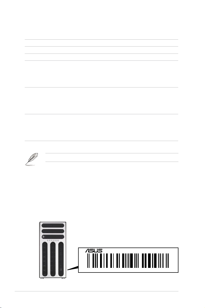
1.2 Serial number label
Before requesting support from the ASUS Technical Support team, you must take
note of the product’s serial number containing 12 characters such as xxxxxxxxxxxx.
See the gure below.
With the correct serial number of the product, ASUS Technical Support team
members can then offer a quicker and satisfying solution to your problems.
TS700-E6/RS8
xxxxxxxxxxxx
Chapter 1: Product introduction1-2
Page 13
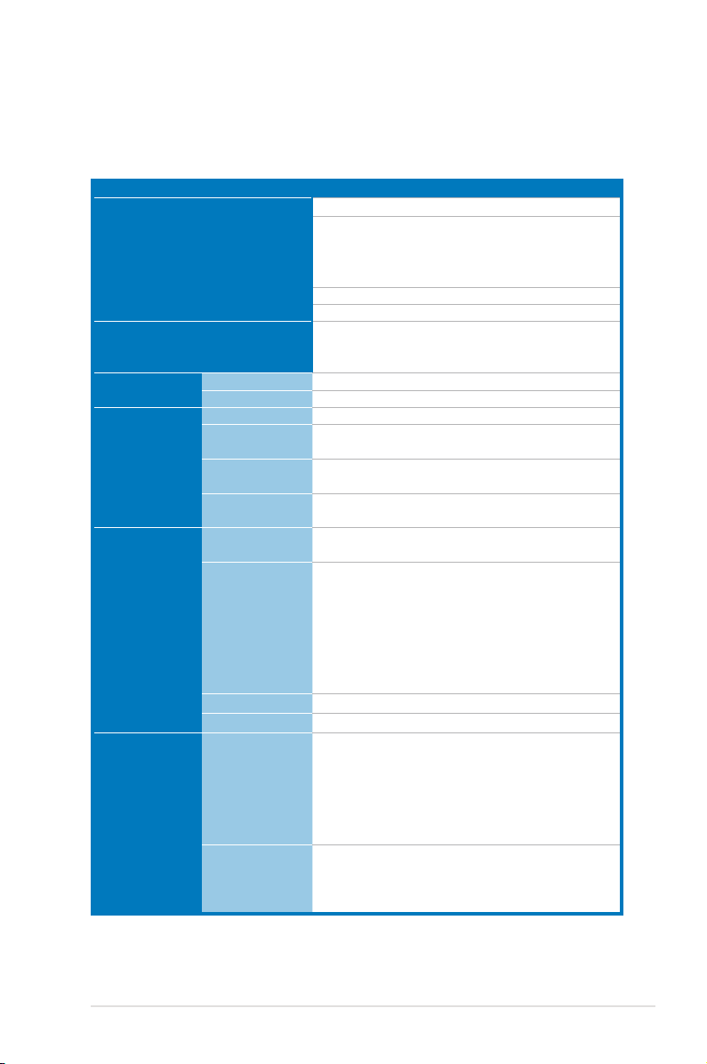
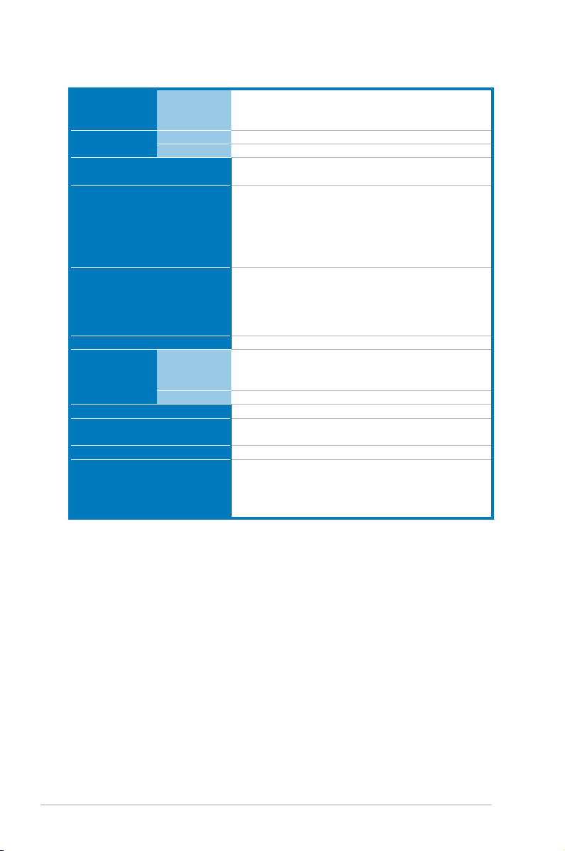
1.3 Systemspecications
The ASUS TS700-E6/RS8 is a 5U barebone server system featuring the ASUS
Z8PE-D12X server board. The server supports Intel® LGA1366 Xeon® 5500 series
processors, plus other latest technologies through the chipsets onboard.
Model Name TS700-E6/RS8
Processor / System Bus
Core Logic
ASUS Features
Memory
Expansion Slots
Storage
Smart Fan
ASWM2.0
Total Slots
Capacity
Memory Type
Memory Size
Total PCI/PCI-X/
PCI-E Slots
Slot Type
Additional Slot 1
Additional Slot 2
SATA Controller
SAS Controller
2 x Socket LGA1366
- Quad-Core Intel
- Quad-Core Intel® Xeon® E5500 Series (80W)
- Quad-Core Intel® Xeon® L5500 Series (60W /
38W)
Quad Core / Dual Core
QPI 4.8 / 5.86 / 6.4 GT/s
Intel® 5520 I/O Hub
Intel® ICH10R I/O controller
NEC uPD720404 PCI-X Bridge
√
√
12 (3-channel per CPU, 6 DIMMs per CPU)
Maximum up to 96GB (RDIMM)
Maximum up to 48GB (UDIMM)
DDR3 1333 / 1066 Reg DIMM / Unbuffered DIMM
with ECC
1GB, 2GB, 4GB and 8GB* (RDIMM)
1GB, 2GB and 4GB (UDIMM)
5 or 6
Workstation Mode:
1 x PCI-E x16 slot (x16 link)
2 x PCI-E x16 slots (x8 link)
2 x PCI-X 100/133MHz slots
Server Mode:
4 x PCI-E x16 slots (x8 link)
2 x PCI-X 100/133MHz slots
1 x PIKE slot for Storage Enhancement
1 x MIO slot for Audio
Intel® ICH10R:
- 6 x SATA2 300MB/s ports
- Intel Matrix Storage (for Windows only)
(Supports software RAID 0, 1, 5 & 10)
LSI MegaRAID (for Linux / Windows)
- Supports software RAID 0, 1 & 10
Optional:
ASUS PIKE 1068E 8-port SAS RAID card
ASUS PIKE 6480 8-port SAS RAID card
ASUS PIKE 1078 8-port SAS HW RAID card
(continued on the next page)
®
Xeon® X5500 Series (95W)
ASUS TS700-E6/RS8 1-3
Page 14
I = internal
HDD Bays
A or S = hot-
8 x Hot-swap 3.5” HDD Bays
swappable
Networking LAN
Graphic VGA
Auxiliary Storage CD / DVD
2 x Intel® 82574L + 1 x Mgmt LAN
Aspeed AST2050 8MB
3 x 5.25” media bays
(Options: No ODD / DVD-ROM / DVD-RW)
1 x External Serial Port
2 x RJ-45 ports
Onboard I/O
4 x USB 2.0 ports (Front x 2, Rear x 2)
1 x VGA port
1 x PS/2 keyboard port
1 x PS/2 mouse port
Windows® Server 2008 Enterprise 32 / 64-bit
Windows® Server 2003 R2 Enterprise 32 / 64-bit
OS Support
RedHat® Enterprise Linux AS5.0 32 / 64-bit
SuSE® Linux Enterprise Server 10 32 / 64-bit
(Subject to change without any notice)
Anti-virus Software
Optional anti-virus CD Pack
Out of Band
Management
Solution
Remote
Management
Software
Dimension (HH x WW x DD)
Net Weight Kg (CPU, DRAM &
HDD not included)
Power Supply
Optional ASMB4-iKVM for KVM-over-IP support
ASUS ASWM 2.0
445mm x 217.5mm x 545mm
17.5 Kg
620W 1+1 Redundant Power Supply
Operation temperature: 10°C–35°C / Non operation
Environment
temperature: -40°C–70°C
Non operation humidity: 20%–90% ( Non-
condensing)
*Specicationsaresubjecttochangewithoutnotice.
®
Chapter 1: Product introduction1-4
Page 15
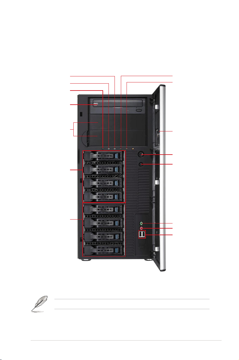
1.4 Front panel features
The barebone server displays a simple yet stylish front panel with easily accessible
features. The drive bays, power and reset buttons, LED indicators, optical drive,
and two USB 2.0 ports are located on the front panel. For future installation of
5.25-inch devices, two drive bays are available.
Message LED
HDD access LED
Power LED
Optical drive
Empty 5.25-inch
bays
4-bay HDD cage
4-bay HDD cage
LAN1 LED
LAN2 LED
Security lock
Power button
Reset button
Headphone
outputjack*
Microphonejack
USB 2.0 ports
*TheaudiojacksfunctiononlywithanoptionalMIOaudiocard.
Refer to section 1.7.1 Front panel LEDs for the LED descriptions.
ASUS TS700-E6/RS8 1-5
Page 16
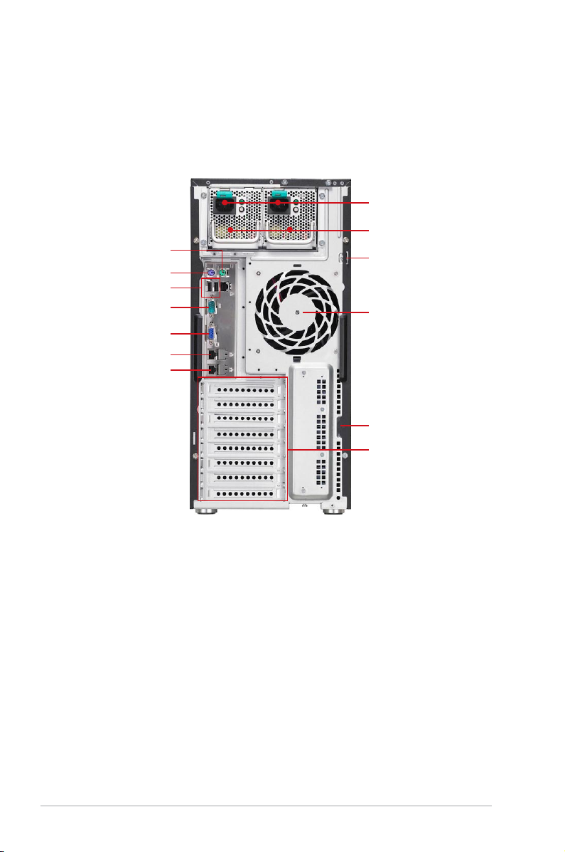
1.5 Rear panel features
The rear panel includes a slot for the motherboard rear I/O ports, expansion slots,
a chassis lock and intrusion switch, a vent for the system fan, and power supply
module.
Power connector
620W Redundant
PS/2 mouse port
PS/2 keyboard port
USB 2.0 ports
Serial port
VGA port
Gigabit LAN port 1
Gigabit LAN port 2
power supply
Chassis lock
120mm x 38mm
system fan
Chassis intrusion switch
Expansion slots
Chapter 1: Product introduction1-6
Page 17
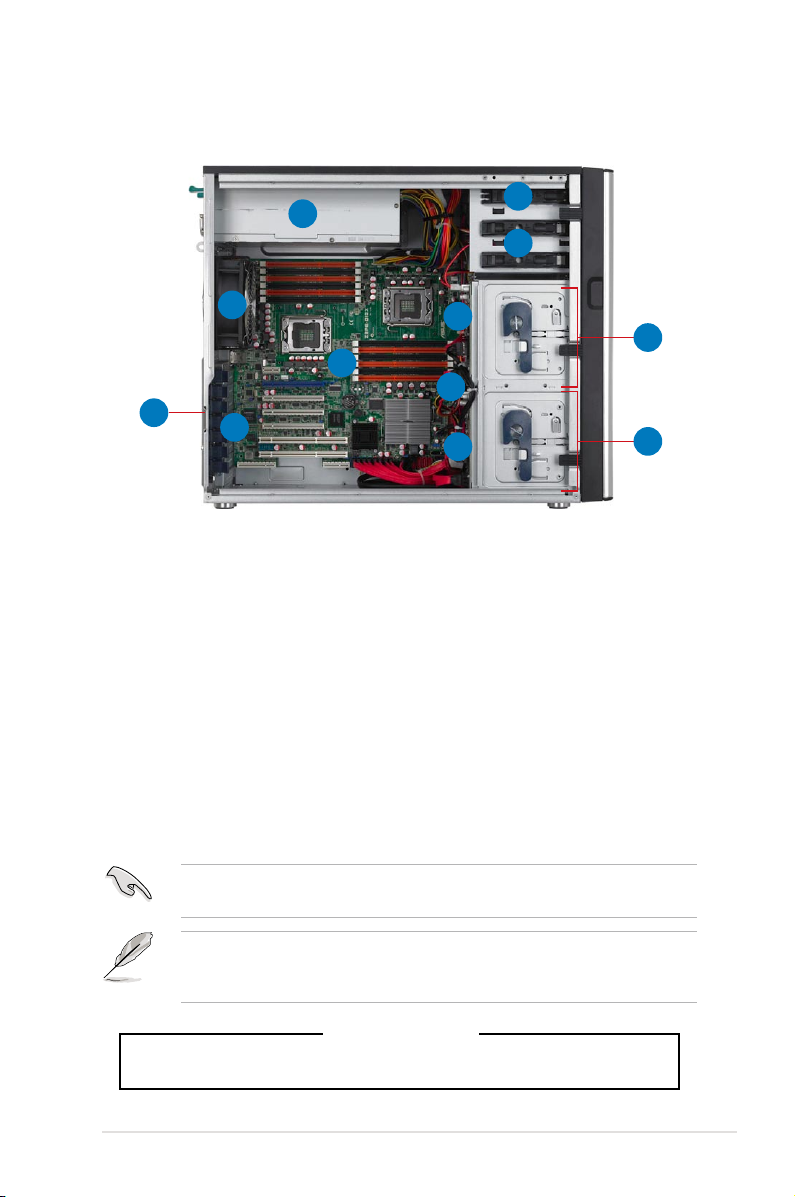
1.6 Internal features
The barebone server includes the basic components as shown.
1
6
7
2
10
3
12
4
5
11
1. 620W Redundant Power Supply (the second set is an optional item)
2. 120mm x 38mm system fan (ARX FD1212-DP284G)
3. ASUS Z8PE-D12X Server Board
4. Chassis intrusion switch
5. Expansion card locks
6. Optical drive
7. 2 x 5.25-inch drive bays
8. 4-bay HDD module (rst set)
9. 4-bay HDD module (second set)
10. SATA/SAS backplane board (rst set, hidden)
11. SATA/SAS backplane board (second set, hidden)
12. 80mm x 38mm system fan (Nidec V80E12BS1A5-07, hidden)
8
9
Turn off the system power and detach the power supply before removing or
replacing any system component.
The barebone server does not include a oppy disk drive and an optical disc
drive. Connect a USB oppy disk drive or a USB ODD to any of the USB ports
on the front or rear panel if you need to use a oppy disk or a optical disc.
*WARNING
HAZARDOUS MOVING PARTS
KEEP FINGERS AND OTHER BODY PARTS AWAY
ASUS TS700-E6/RS8 1-7
Page 18
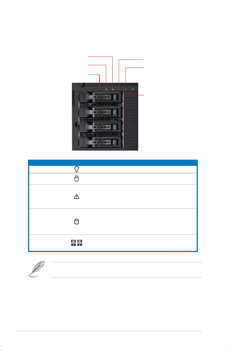
1.7 LED information
1.7.1 Front panel LEDs
Message LED
HDD Access LED
Power LED
LED Icon Display status Description
Power LED ON System power ON
HDD Access LED
Message LED
Drive status LED
LAN LEDs
OFF
Blinking
OFF
Lighting up
Green
Red
Green/Red blinking
OFF
Blinking
ON
LAN1 LED
LAN2 LED
Drive Status LED
No activity
Read/write data into the HDD
System is normal; no incoming event
A hardware temperature overheat is
detected. Use ASWM to check the
abnormal status.
Bridge board connected to backplane
Installed HDD is in good condition
HDD failure
HDD rebuilding using the RAID card
LAN accessing
The Power, HDD Access, LAN and Message LEDs are visible even if the system
front bezel is closed.
Chapter 1: Product introduction1-8
Page 19
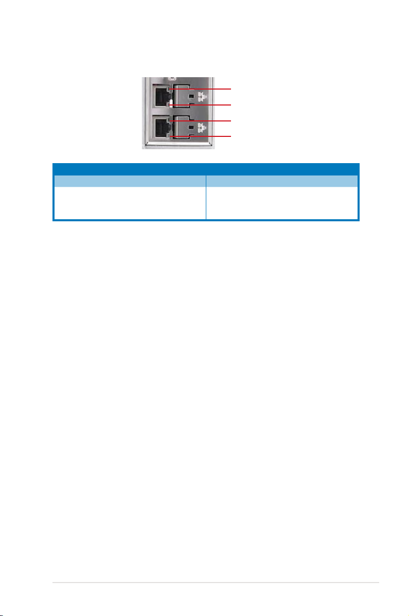
1.7.2 Rear panel LEDs
ACT/LINK LED
SPEED LED
ACT/LINK LED
SPEED LED
ACT/LINK LED SPEED LED
Status Description Status Description
OFF No link OFF 10 Mbps connection
GREEN Linked ORANGE 100 Mbps connection
BLINKING Data activity GREEN 1 Gbps connection
ASUS TS700-E6/RS8 1-9
Page 20

Chapter 1: Product introduction1-10
Page 21

Chapter 2
This chapter lists the hardware setup
procedures that you have to perform
when installing or removing system
components.
ASUS TS700-E6/RS8
Hardware setup
Page 22
2.1 Chassis cover
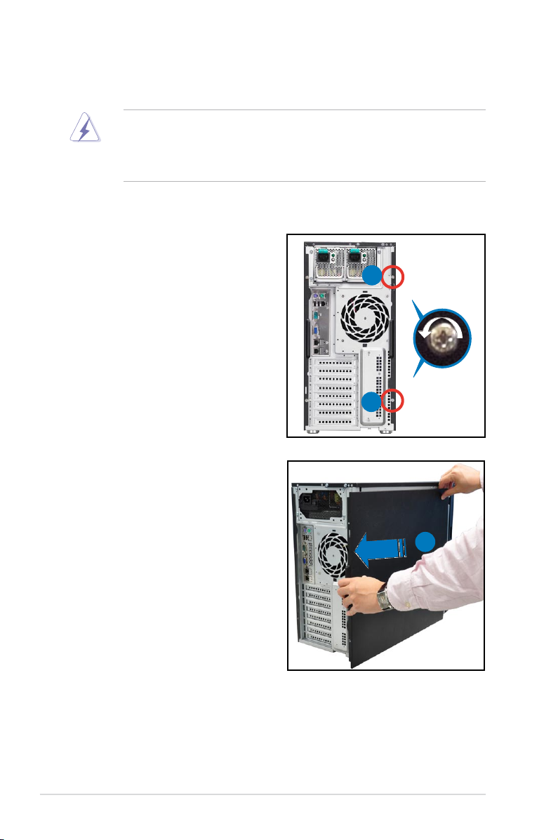
2.1.1 Removing the side cover
• Ensure that you unplug the power cord before removing the side cover.
• Take extra care when removing the side cover. Keep your ngers from
components inside the chassis that can cause injury, such as the CPU fan,
rear fan, and other sharp-edged parts.
To remove the side cover
1. Remove the two screws that secure
the side cover.
2. Slide the side cover for about half
an inch toward the rear until it is
disengaged from the chasssis.
3. Carefully lift the side cover and set
it aside.
1
1
2
Chapter 2: Hardware setup2-2
Page 23
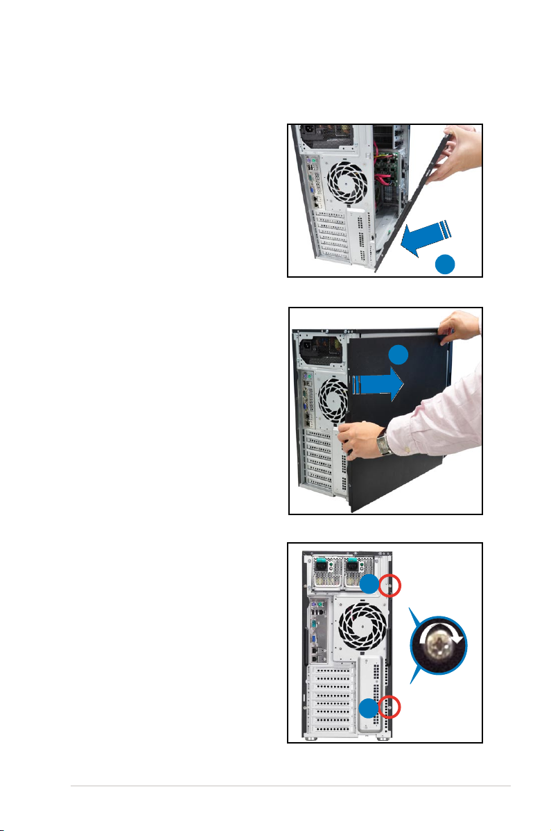
2.1.2 Reinstalling the side cover
To reinstall the side cover:
1. Match and insert the lower sliding
edge of the side cover to the
corresponding chassis edge.
2. Position the side cover to the
chassis.
3. Slide the side cover toward the
front panel until it snaps in place.
1
3
4. Drive in the two screws you
removed earlier to secure the side
cover.
4
4
2-3ASUS TS700-E6/RS8
Page 24
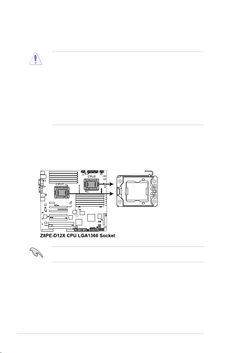
2.2 Central Processing Unit (CPU)
The motherboard comes with dual surface mount LGA 1366 Socket designed for
the Intel® Xeon 5500 series CPU in the Land Grid Array (LGA) package.
• Upon purchase of the motherboard, ensure that the PnP cap is on
the socket and the socket contacts are not bent. Contact your retailer
immediately if the PnP cap is missing, or if you see any damage to the PnP
cap/socket contacts/motherboard components. ASUS shoulders the repair
cost only if the damage is shipment/transit-related.
• Keep the cap after installing the motherboard. ASUS will process Return
Merchandise Authorization (RMA) requests only if the motherboard comes
with the cap on the Socket 1366.
• The product warranty does not cover damage to the socket contacts
resulting from incorrect CPU installation/removal, or misplacement/loss/
incorrect removal of the PnP cap.
2.2.1 Installing the CPU
To install a CPU:
1. Locate the CPU socket on the motherboard.
Before installing the CPU, ensure that the socket box is facing towards you and
the load lever is on your left.
Chapter 2: Hardware setup2-4
Page 25
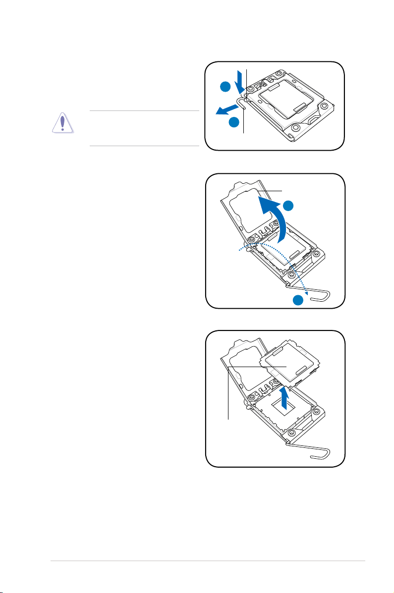
2. Press the load lever with your
thumb (A), then move it to the left
(B) until it is released from the
retention tab.
Retention tab
A
To prevent damage to the socket
pins, do not remove the PnP cap
unless you are installing a CPU.
3. Lift the load lever in the direction of
the arrow to a 135º angle.
4. Lift the load plate with your thumb
and forenger to a 100º angle.
5. Remove the PnP cap from the CPU
socket.
B
Load lever
Load plate
4
3
PnP cap
2-5ASUS TS700-E6/RS8
Page 26
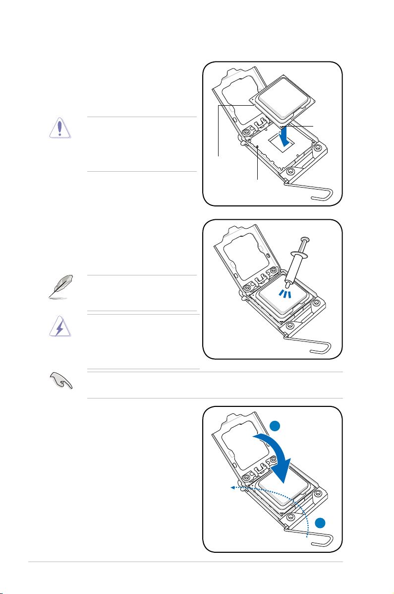
6. Position the CPU over the socket,
ensuring that the gold triangle is on
the bottom-left corner of the socket,
and then t the socket alignment key
into the CPU notch.
The CPU ts in only one correct
orientation. DO NOT force the
CPU into the socket to prevent
bending the connectors on the
socket and damaging the CPU!
7. Apply several drops of thermal paste
to the exposed area of the CPU that
the heatsink will be in contact with,
ensuring that it is spread in an even
thin layer.
Some heatsinks come with preapplied thermal paste. If so, skip
this step.
The thermal paste is toxic and
inedible. If it gets into your eyes
or touches your skin, ensure to
wash it off immediately and seek
professional medical help.
Gold
triangle
mark
CPU notch
Alignment key
To prevent contaminating the paste, DO NOT spread the paste with your nger
directly.
8. Close the load plate (A), and then
push the load lever (B) until it snaps
into the retention tab.
A
B
Chapter 2: Hardware setup2-6
Page 27
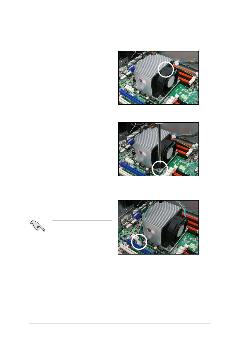
2.2.2 Installing the CPU heatsink and fan
To install the CPU heatsink and fan:
1. Place the CPU heatsink and fan on
top of the installed CPU, ensuring
that the four screws match the holes
on the support plate, and the arrow
on the fan faces to rear panel of the
server chassis.
2. Twist each of the four screws with
a Philips (cross) screwdriver just
enough to attach the CPU heatsink
and fan to the motherboard. When
the four screws are attached,
tighten them one by one to
completely secure the CPU
heatsink and fan.
3. Connect the CPU heatsink and
fan cable to the connector on the
motherboard.
Do not forget to connect
the CPU heatsink and fan
connector! Hardware monitoring
errors can occur if you fail to
plug this connector.
2-7ASUS TS700-E6/RS8
Page 28
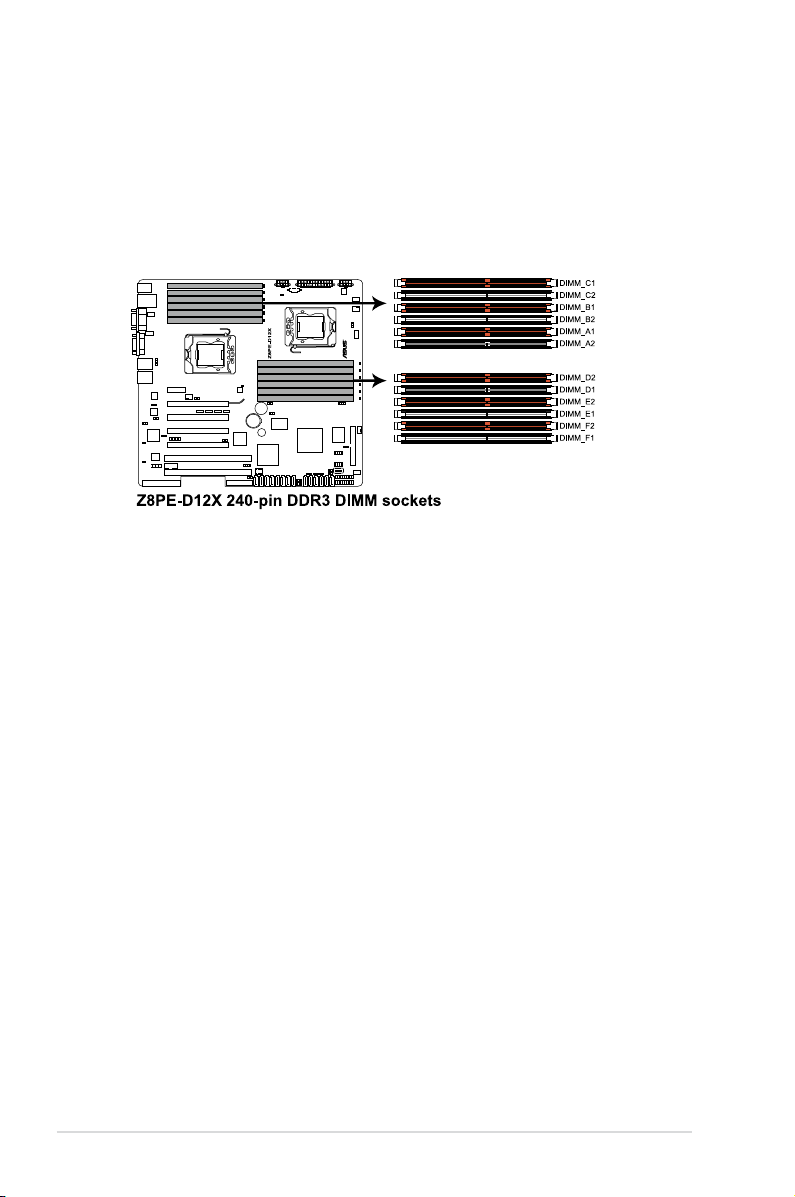
2.3 System memory
2.3.1 Overview
The motherboard comes with twelve (12) Double Data Rate 3 (DDR3) Dual Inline
Memory Modules (DIMM) sockets.
The gure illustrates the location of the DDR3 DIMM sockets:
Chapter 2: Hardware setup2-8
Page 29
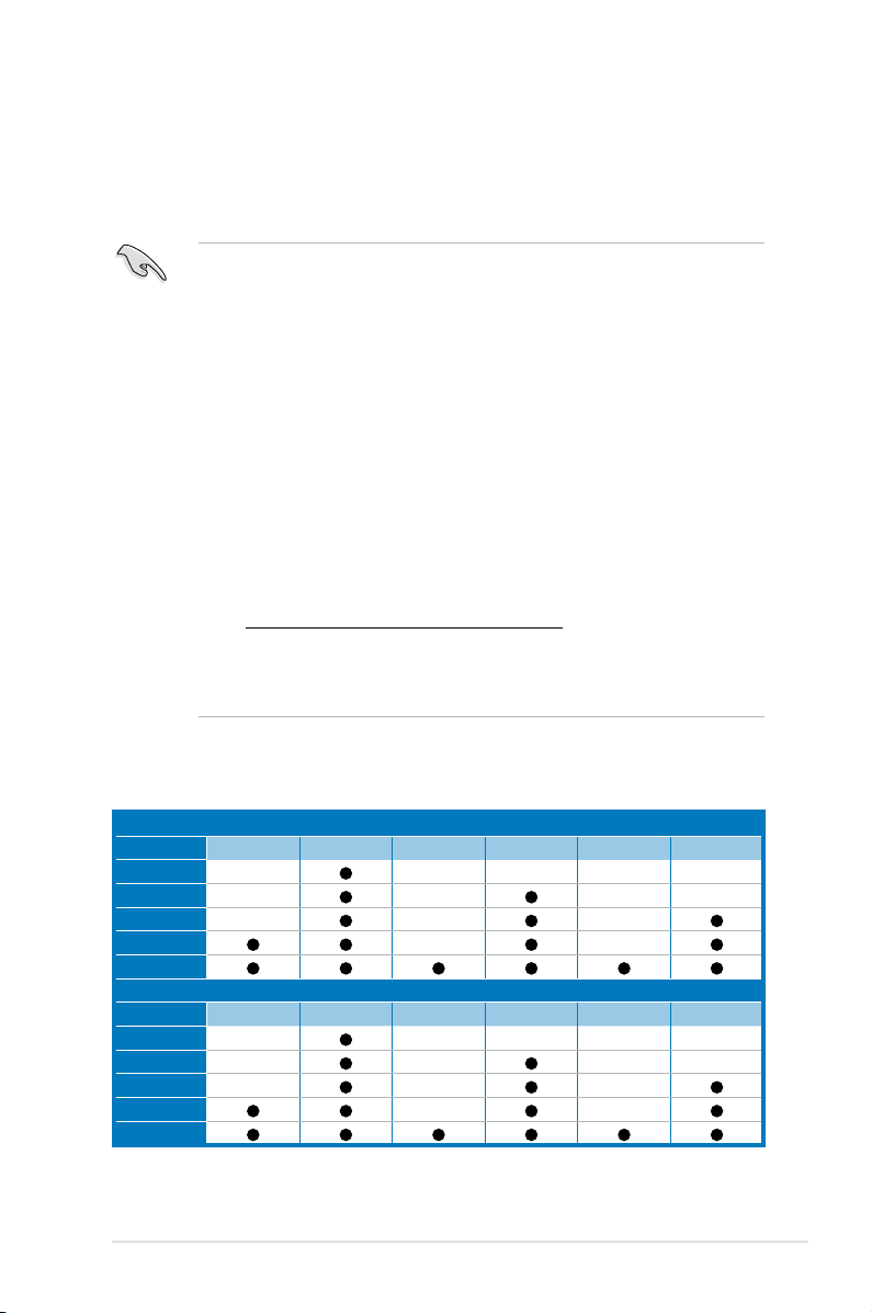
2.3.2 MemoryCongurations
You may install 1 GB, 2 GB, 4 GB,or 8 GB Registerd or Unbuffered with ECC/
Non-ECC DDR3 DIMMs into the DIMM sockets using the memory congurations in
this section.
• Always install DIMMs with the same CAS latency. For optimum
compatibility, we recommend that you obtain memory modules from the
same vendor. Refer to the Qualied Vendors List on the ASUS web site.
• You may install varying memory sizes in Channel A, Channel B and
Channel C. The system maps the total size of the lower-sized channel for
the dual-channel or triple-channel conguration. Any excess memory from
the higher-sized channel is then mapped for single-channel operation.
• Due to the memory address limitation on 32-bit Windows OS, when you
install 4GB or more memory on the motherboard, the actual usable memory
for the OS can be about 3GB or less. For effective use of memory, we
recommend that you do any of the following:
- Use a maximum of 3GB system memory if you are using a 32-bit Windows
OS.
- Install a 64-bit Windows OS when you want to install 4GB or more on the
motherboard.
For more details, refer to the Microsoft® support site at
http://support.microsoft.com/kb/929605/en-us.
• This motherboard does not support DIMMs made up of 256 Mb (32MB)
chips or less (Memory chip capacity counts in Megabit, 8 Megabit/Mb = 1
Megabyte/MB).
Memory population table
CPU1Conguration
DIMM_A2 DIMM_A1 DIMM_B2 DIMM_B1 DIMM_C2 DIMM_C1
1 DIMMs
2 DIMMs
3 DIMMs
4 DIMMs
6 DIMMs
CPU2Conguration
1 DIMMs
2 DIMMs
3 DIMMs
4 DIMMs
6 DIMMs
-- -- -- -- --
-- -- -- --
-- -- --
DIMM_D2 DIMM_D1 DIMM_E2 DIMM_E1 DIMM_F2 DIMM_F1
-- -- -- -- --
-- -- -- --
-- -- --
-- --
-- --
2-9ASUS TS700-E6/RS8
Page 30
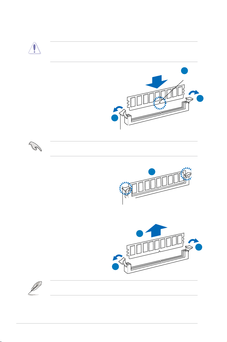
2.3.3 Installing a DIMM
Ensure to unplug the power supply before adding or removing DIMMs or other
system components. Failure to do so may cause severe damage to both the
motherboard and the components.
1. Unlock a DIMM socket by pressing
the retaining clips outward.
2. Align a DIMM on the socket
such that the notch on the DIMM
matches the break on the socket.
Unlocked retaining clip
A DIMM is keyed with a notch so that it ts in only one direction. DO NOT force
a DIMM into a socket to avoid damaging the DIMM.
2
DIMM notch
1
1
3. Firmly insert the DIMM into the
socket until the retaining clips snap
back in place and the DIMM is
properly seated.
Locked Retaining Clip
2.3.4 Removing a DIMM
Follow these steps to remove a DIMM.
1. Simultaneously press the
retaining clips outward to unlock
the DIMM.
1
Support the DIMM lightly with your ngers when pressing the retaining clips.
The DIMM might get damaged when it ips out with extra force.
2. Remove the DIMM from the socket.
3
2
1
Chapter 2: Hardware setup2-10
Page 31

2.4 Front panel assembly
Before you can install a 5.25-inch drive, you should rst remove the front panel
assembly (front bezel and front panel cover).
2.4.1 Removing the front panel assembly
To remove the front panel assembly
1. Locate the three hooked tabs on the chassis
side rail.
2. Shift the hooked tabs and take off the front
bezel.
2.4.2 Reinstalling the front panel assembly
To reinstall the front panel assembly:
1. Hook the other side of the front
panel assembly to the chassis.
2. Swing the front panel assembly and
snap it back into place.
2-11ASUS TS700-E6/RS8
Page 32

2.5 5.25-inch drives
Ensure to unplug the power cable before installing or removing any system
components. Failure to do so may cause damage to the motherboard and other
system components!
The system comes with three 5.25-inch
drive bays located on the upper front
part of the chassis. An optical drive that
comes standard/optional with the system
package occupies the uppermost bay
(labeled 1). The lower bays (labeled 2 and
3) are available for additional 5.25-inch
optical, zip, or oppy disk drives.
You must remove the front panel
assembly before installing a
5.25-inch drive.
Installing a 5.25-inch drive
1. Unscrew and remove the metal
cover of the bay where you want to
install the 5.25-inch drive, and take
off the plastic cover on the front
bezel at the same position.
2. Insert the drive into the bay and
slide the bay lock to the right until it
clicks in place.
1
2
3
2
3. Connect the SATA cable to the
SATA connector on the back of the
drive.
4. Connect a power plug from
the power supply to the power
connector on the back of the drive.
4
3
Chapter 2: Hardware setup2-12
Page 33

2.6 SATA/SAS hard disk drives
The hard disk drive module cage on the front panel, including externally removable
trays for mounting either SATA or SAS hard disk drives, allows you to access the
drive trays by simply opening the front bezel.
An HDD module cage comes with a SATA or SAS backplane. Ensure of the type
of HDD module cage you purchase before buying hard disks.
2.6.1 Installing the HDD module cage
1. Examine the chassis and ensure the bay space is free of wires and other
obstructions.
2. Level the HDD module cage latch
counterclockwise.
3. Insert the HDD module cage into the
bay.
2
4. When the HDD module cage is
completed inserted, the cage latch
will be pushed back clockwise.
4
3
5. Lock the cage latch properly.
6. Connect the appropriate cables to
the SATA/SAS backplane on the
HDD module cage.
5
2-13ASUS TS700-E6/RS8
Page 34

2.6.2 Removing the HDD module cage
1. Disconnect the all cables from the SATA/SAS backplane on the HDD module
cage.
Level the HDD module cage latch
2.
counterclockwise. The HDD module
cage will be pushed out of the
chassis.
2
3. Completely pull out the HDD module
cage.
2.6.3 Installing a hot-swap SATA/SAS hard disk drive
1. Release a drive tray by pushing the
spring lock to the right, and then
pulling the tray lever outward. The
drive tray ejects slightly after you
pull out the lever.
Chapter 2: Hardware setup2-14
Page 35

2. Firmly hold the tray lever and pull
the drive tray out of the bay.
3. Take note of the drive tray holes.
Each side has three holes to t
different types of hard disk drives.
Use two screws on each side to
secure the hard disk drive.
4. Place a SATAII/SAS hard disk drive
on the tray, and then secure it with
four screws.
5. Carefully insert the drive tray and
push it all the way to the depth of
the bay until just a small fraction of
the tray edge protrudes.
When installed, the SATAII/SAS connector on the drive connects to the SATAII/
SAS interface on the backplane.
2-15ASUS TS700-E6/RS8
Page 36

6. Push the tray lever until it clicks,
and secures the drive tray in place.
The drive tray is correctly placed
when its front edge aligns with the
bay edge.
7. Repeat steps 1 to 6 if you wish to
install a second SATAII/SAS drive.
2.6.4 Removing and reinstalling the backplane
DO NOT remove the backplane unless necessary!
1. Remove all hot-swap HDD trays
from the chassis.
2. Disconnect all cables from the
SATA/SAS backplane.
3. Loosen the four screws on the
backplane.
4. Firmly hold the backplane, lift it up
and remove it from the module.
5. Follow the previous instructions in
reverse to reinstall the backplane.
Chapter 2: Hardware setup2-16
Page 37

2.7 Expansion cards
The system is designed with an expansion card lock on the rear panel for you to
install or remove an expansion card in less steps.
Ensure to unplug the power cord before installing or removing expansion cards.
Failure to do so may cause severe damage to the motherboard and other
system components!
2.7.1 Installing an expansion card
1. Before installing the expansion card, read the documentation that came with
it and make the necessary hardware settings for the card.
2. Lay the system on its side on a at, stable surface.
3. Push down the expansion card
lock latch (step a) and lift up the
expansion card lock (step b), as
shown in the right gure.
Expansion card lock latches
Expansion card locks
4. Remove the metal slot cover
opposite the slot where you wish to
install an expansion card.
a
b
5. Align the card golden ngers with
the slot, and then press rmly until
the card is completely seated on
the slot.
2-17ASUS TS700-E6/RS8
Page 38

6. Restore the expansion card lock
to its original position. A light click
indicates that the card is locked in
place.
When installing a graphics
card on PCI-E x16 slot, the
PCI-E slot right beside it does
not function.
2.7.2 Installing ASUS PIKE RAID card
Follow the steps below to install an optional ASUS RAID card on your motherboard.
1. Locate the PIKE RAID card slot on
the motherboard.
2. Align the golden ngers of the RAID
card with the PIKE RAID card slot.
Chapter 2: Hardware setup2-18
Page 39

3. Insert the RAID card into the
PIKE RAID card slot. Ensure it is
completely seated on the PIKE
RAID card slot.
4. Ensure to connect the data cables
to the SAS connectors on the
motherboard.
2.7.3 Installing i Button
Follow the steps below to install an optional i Button on your motherboard.
1. Locate the i Button slot on the
motherboard.
2. Snap the i Button in place.
You need to install i Button before using PIKE 1078 functions.
2-19ASUS TS700-E6/RS8
Page 40

2.7.4 Installing ASMB4 management board
Follow the steps below to install an optional ASMB4 management board on your
motherboard.
1. Locate the BMC_FW header on the
motherboard.
2. Orient and press the ASMB4
management card in place.
3. Insert the LAN cable plug to the LAN port 3 (dedicated LAN) or LAN port 1
(shared LAN) for server management.
LAN port 3
LAN port 1
Chapter 2: Hardware setup2-20
Page 41

2.7.5 Conguringanexpansioncard
After installing the expansion card, congure the it by adjusting the software settings.
1. Turn on the system and change the necessary BIOS settings, if any. See
Chapter 5 for information on BIOS setup.
2. Assign an IRQ to the card. Refer to the following tables.
3. Install the software drivers for the expansion card.
Standard Interrupt assignments
IRQ Priority Standard function
0 1 System Timer
1 2 Keyboard Controller
2 - Programmable Interrupt
3* 11 Communications Port (COM2)
4* 12 Communications Port (COM1)
5* 13 -6 14 Floppy Disk Controller
7* 15 -8 3 System CMOS/Real Time Clock
9* 4 ACPI Mode when used
10* 5 IRQ Holder for PCI Steering
11* 6 IRQ Holder for PCI Steering
12* 7 PS/2 Compatible Mouse Port
13 8 Numeric Data Processor
14* 9 Primary IDE Channel
15* 10 Secondary IDE Channel
* These IRQs are usually available for ISA or PCI devices.
2-21ASUS TS700-E6/RS8
Page 42

2.8 Cable connections
• The bundled system cables are pre-connected before shipment. You do
not need to disconnect these cables unless you will remove pre-installed
components to install additional devices.
• Refer to Chapter 4 for detailed information on the connectors.
2.8.1 Motherboard connections
2 1 2
3
4
4
7
5
4
10
8
Standard cables connected to the motherboard
1. 24-pin SSI power connector (from power supply to motherboard)
2. 8-pin 12V power connector (from power supply to motherboard)
3. Power supply SMBus connector (from power supply to motherboard)
4. System fan connectors (from system fan to motherboard)
5. USB connector (from motherboard to front I/O board)
6. Chassis Intrusion connector (from rear chassis intrusion switch to motherboard)
7. IDE connector (from motherboard to the optical drive)
8. Serial General Purpose Input/Output connectors
(SATA: from motherboard SGPIO1 to SATA/SAS backplane J2 connector
SAS: from motherboard SGPIO2 to SATA/SAS backplane J7 connector
SAS: from motherboard SGPIO3 to SATA/SAS backplane J6 connector)
9. System panel connector (from motherboard to front I/O board)
10. SAS connectors (for ASUS PIKE only; from motherboard to SATA/SAS backplane)
6
9
4
4
4
Chapter 2: Hardware setup2-22
Page 43

2.8.2 SATA/SAS backplane connections
A SATA/SAS backplane comes pre-installed in the TS700-E6/RS8. The SATA/SAS
backplane has four 22-pin SATA/SAS connectors to support Serial ATA hard disk
drives and SAS hard disk drives. The backplane design incorporates a hot swap
feature to allow easy connection or removal of SATA/SAS hard disks. The LEDs on
the backplane connect to the front panel LEDs to indicate HDD status. See section
1.7 LED information for details.
Front side
The front side of the SATA/SAS backplane faces the front panel when installed.
This side includes four SATA/SAS connectors for the hot swap drive trays.
HDD1
HDD2
Drive status LEDs
HDD3
HDD4
Each SATA/SAS connector is labeled (HDD1,
HDD2, HDD3, HDD4) so you can easily
determine their counterpart connectors at the
back side of the backplane. Refer to the table
for reference.
HDD Device Front side connector Back side connector
HDD 1 HDD1 CON1
HDD 2 HDD2 CON2
HDD 3 HDD3 CON3
HDD 4 HDD4 CON4
2-23ASUS TS700-E6/RS8
Page 44

Back side
The back side of the SATA/SAS backplane faces the rear panel when installed.
This side includes the power connectors and SATA/SAS interfaces for the
motherboard Serial ATA connectors or the SAS card.
U1
CON1
CON2
SGPIO_SEL1
CON4
SGPIO2
CON3
SGPIO1
BPSMB1
Connectors Description
SGPIO1
SGPIO2
BPSMB1
U1
CON1/CON2/
CON3/CON4
Move the
Connects to SATA SGPIO1 connector on the motherboard
Connects to SAS SGPIO2 connector on the motherboard
Connects to Front panel SMB connector on the motherboard
Connects to 4-pin plug of the power supply
Connects to SATA/SAS connectors on the motherboard
SGPIO_SEL1
jumper on the SATA/SAS backplane to 2–3 when
installing the PIKE RAID card.
Chapter 2: Hardware setup2-24
Page 45

2.9 Removable components
You may need to remove previously installed system components when installing
or removing system devices, or when you need to replace defective components.
This section tells how to remove the following components:
1. System fans (front and rear)
2. Chassis footpads
3. Redundant power supply module
2.9.1 System fan
Removing the front system fan
To remove the front system fan
1. Remove the two screws that secure
the right side cover.
1
1
2. Locate the front system fan near
the 5.25-inch drive bays.
3. Squeeze the front system fan
latches (step a) and pull out the
front system fan (step b), as shown
in the right gure.
4. Follow the previous instructions in
reverse to reinstall the front system
fan.
a
b
a
2-25ASUS TS700-E6/RS8
Page 46

Removing the rear system fan
To remove the rear system fan
1. Unplug the system fan cable from
the REAR_FAN1 connector on the
motherboard.
2. Shift the two hooked tabs leftward
and rightward respectively.
3. Carefully take off the system fan.
4. Follow the previous instructions in
reverse to reinstall the rear system
fan.
Chapter 2: Hardware setup2-26
Page 47

2.9.2 Chassis footpads
The barebone server system is shipped with four footpads attached to the bottom
of the chassis for stability. You need to remove these footpads if you wish to install
the system to a rack (Refer to Chapter 3: Installation options of this user guide,
and to the “Rackmount Kit” user guide for instructions)
To remove the footpads
1. Lay the system chassis on its side.
2. Remove the footpad by rotating
it counterclockwise with a Philips
(cross) screwdriver.
3. Repeat step 1 and 2 to remove the
other three footpads.
2-27ASUS TS700-E6/RS8
Page 48

2.9.3 Redundant power supply module
The system is compatible with the 620W redundant power supply. Purchase based
on your needs.
You MUST disconnect all power cable plugs from the motherboard and other
installed devices before removing the power supply unit.
To install a second redundant power supply module:
1. Remove the redundant power
supply dummy cover.
2. Take out the seocond redundant
power supply module from its
package. Slide it into the chassis.
3. Firmly pull the lever to slide the
power supply module into the
chassis.
Chapter 2: Hardware setup2-28
Page 49

Chapter 3
This chapter describes how to install the
optional components and devices into
the barebone server.
ASUS TS700-E6/RS8
Installation options
Page 50

3.1 Preparing the system for rack mounting
• The items required for the optional congurations described in this chapter
are not included in the standard barebone system package. These items
are purchased separately.
• We recommend that you allot at least 1U space above the server system to
ensure optimal thermal performance.
Removing the footpads
Refer to section 2.9.2 Chassis footpads for instructions on removing the footpads.
Removing the top cover
Unscrew and slide the top cover toward
the rear panel, and then lift it up from the
chassis.
3.2 Attaching the inner rail to the server
1. Slide out the inner rail from the rackmount rail kit.
2. Align the screw holes on the inner
rail and the chassis top, and then
secure the inner rail to the chassis
top with screws.
3. Repeat the previous steps to
secure the other inner rail to the
bottom of the chassis with screws.
Chapter 3: Installation options3-2
Page 51

3.3 Attaching the rails to the rack
To attach the rails to the rack:
1. Select one unit of space (1U) on the rack
where you wish to install the server.
1U space
2. Loosen the two screws on the rack
rails.
3. Align the front end holes of a rack
rail pair to the 1U space.
4. Drive in two screws on the outer
holes to secure the front end.
5. Find the rear 1U space that corresponds to the front 1U space where you
attached the rail.
6. Drive in two screws on the outer holes to secure the rear end.
7. From the rack front, nd the corresponding 1U space for the second rail pair.
8. Repeat steps
3–6 to attach the second rail pair.
3-3ASUS TS700-E6/RS8
Page 52

3.4 Mounting the server to the rack
To mount the server to the rack:
1. Align the server rails with the rack rails.
2. Push the server all the way into the rack.
Chapter 3: Installation options3-4
Page 53

Chapter 4
This chapter includes the motherboard
layout and brief descriptions of the
jumpers and internal connectors.
ASUS TS700-E6/RS8
Motherboard Info
Page 54

4.1 Motherboard layout
Chapter 4: Motherboard information4-2
Page 55

Layout contents
Jumpers Page
1. Clear RTC RAM (CLRTC1)
2. VGA controller setting (3-pin VGA_SW1))
3. CPU Fan and Chassis Fan control setting
(3-pin CPUFAN_SEL1, CHAFAN_SEL1)
4. LAN controller setting (3-pin LAN_SW1, LAN_SW2)
5. IDE control setting (3-pin IDE_SW1)
6. PCI-X Slot control setting (3-pin PCIX_SPEED1)
7. DDR3 voltage control setting
(4-pin LVDDR3_SEL1; LVDDR3_SEL2)
8. Force BIOS recovery setting (3-pin RECOVERY1)
Internal connectors Page
1. Serial ATA connectors
(7-pin SATA1, SATA2, SATA3, SATA4; RED)
(7-pin SATA5, SATA6; Black)
2. IDE
3. SAS connectors
(7-pin SAS1, SAS2, SAS3, SAS4; Red)
(7-pin SAS5, SAS6, SAS7, SAS8; Blue)
4. Hard disk activity LED connector (4-pin HDLED1)
5. USB connector (10-1 pin USB34, USB56; A-Type USB7)
6. Thermal sensor cable connectors (3-pin TR1, TR2)
7. CPU, front and rear fan connectors
(4-pin CPU_FAN1, CPU_FAN2, FRNT_FAN1, FRNT_FAN2,
FRNT_FAN3, FRNT_FAN4, REAR_FAN1, REAR_FAN2)
8. LPC debug card connector (14-1 pin LPC1)
9. Serial General Purpose Input/Output connector (6-1 pin SGPIO1)
10. Serial General Purpose Input/Output connectors
(8-1 pin SGPIO2/3)
11. Serial port connector (10-1 pin COM2)
12. BMC header (BMC_FW1)
13. Power Supply SMBus
14. SSI power
(24-pin SSIPWR1, 8-pin SSI12V1, 8-pin SSI12V2)
15. System panel
16. Auxiliary panel connector (20-2 pin AUX_PANEL1)
connector (40-1 pin PRI_EIDE1)
connectors
connector (20-1 pin PANEL1)
connector (5-pin PSUSMB1)
4-4
4-5
4-5
4-6
4-6
4-7
4-7
4-8
4-9
4-10
4-11
4-11
4-12
4-12
4-13
4-13
4-14
4-14
4-15
4-15
4-16
4-16
4-17
4-18
ASUS TS700-E6/RS8 4-3
Page 56

4.2 Jumpers
1. Clear RTC RAM (CLRTC1)
This jumper allows you to clear the Real Time Clock (RTC) RAM in CMOS.
You can clear the CMOS memory of date, time, and system setup parameters
by erasing the CMOS RTC RAM data. The onboard button cell battery
powers the RAM data in CMOS, which include system setup information such
as system passwords.
To erase the RTC RAM:
1. Turn OFF the computer and unplug the power cord.
2. Move the jumper cap from pins 1–2 (default) to pins 2–3. Keep the cap
on pins 2–3 for about 5–10 seconds, then move the cap back to pins 1–2.
3. Plug the power cord and turn ON the computer.
4. Hold down the <Del> key during the boot process and enter BIOS setup
to re-enter data.
Except when clearing the RTC RAM, never remove the cap on CLRTC jumper
default position. Removing the cap will cause system boot failure!
If the steps above do not help, remove the onboard battery and move the
jumper again to clear the CMOS RTC RAM data. After the CMOS clearance,
reinstall the battery.
Chapter 4: Motherboard information4-4
Page 57

2. VGA controller setting (3-pin VGA_SW1)
This jumper allows you to enable or disable the onboard VGA controller. Set
to pins 1–2 to activate the VGA feature.
3. CPU Fan and Chassis Fan control setting
(3-pin CPUFAN_SEL1, CHAFAN_SEL1)
These jumpers allow you to switch for fan pin selection. The CPUFAN_SEL1
jumper is for the CPU fans control and the CHAFAN_SEL1 jumper is for the
front fans and rear fans control. Set to pins 1–2 when using 4-pin fans or pins
2–3 when using 3-pin fans.
• If you use a 4-pin fan but set the jumper to pin 2-3, the fan you installed
may not work.
• If you use a 3-pin fan but set the jumper for a 4-pin fan, the fan control will
not work and the fan you installed will always run at full speed.
ASUS TS700-E6/RS8 4-5
Page 58

4. LAN controller setting (3-pin LAN_SW1, LAN_SW2)
These jumpers allow you to enable or disable the onboard Intel
®
Intel
82574LGigabit LAN controllers. Set to pins 1-2 to activate the Gigabit LAN
feature.
5. IDE control setting (3-pin IDE_SW1)
This jumper allows you to enable or disable the IDE connector. Set to pins 1–
2 to enable the IDE connector or pins 2–3 disable the IDE connector.
Chapter 4: Motherboard information4-6
Page 59

6. PCI-X Slot control setting (3-pin PCIX_SPEED1)
This jumper enables both PCI-X slots to run at the speed of 133MHz. Set to
pins 1–2 to Auto Mode or pins 2–3 to Force 133 MHz.
Force 133MHz may cause the system unstable.
7. DDR3 voltage control setting (4-pin LVDDR3_SEL1; LVDDR3_SEL2)
These jumpers allow you to adjust the DIMM voltage. Set to pins 1–2 to
select 1.5V BIOS control, pins 2–3 to select 1.2V Force or 3–4 to select 1.35V
Force.
ASUS TS700-E6/RS8 4-7
Page 60

8. Force BIOS recovery setting (3-pin RECOVERY1)
This jumper allows you to quickly update or recover the BIOS settings when it
becomes corrupted.
To update the BIOS:
1. Prepare a USB ash disk that contains the original or latest BIOS for the
motherboard (XXXXXX.ROM) and the AFUDOS.EXE utility.
2. Set the jumper to pins 2–3.
3. Insert the USB ash and turn on the system to update the BIOS.
4. Shut down the system.
5. Set the jumper back to pins 1–2.
6. Turn on the system.
Chapter 4: Motherboard information4-8
Page 61

4.3 Internal connectors
1. Serial ATA connectors
(7-pin SATA1, SATA2, SATA3, SATA4; RED)
(7-pin SATA5, SATA6; Black)
Supported by the Intel® ICH10R chipset, these connectors are for the Serial
ATA signal cables for Serial ATA hard disk drives that allows up to 3Gb/s of
data transfer rate.
If you installed Serial ATA hard disk drives, you can create a RAID 0, RAID 1,
RAID 10, or RAID 5 conguration.
The actual data transfer rate depends on the speed of Serial ATA hard disks
installed.
ASUS TS700-E6/RS8 4-9
Page 62

2. IDE connector (40-1 pin PRI_EIDE1)
This connector is for an Ultra DMA 133/100/66 signal cable. The Ultra
DMA 133/100/66 signal cable has three connectors: a blue connector for
the primary IDE connector on the motherboard, a black connector for an
Ultra DMA 133/100/66 IDE slave device (optical drive/hard disk drive), and
a gray connector for an Ultra DMA 133/100/66 IDE master device (hard disk
drive). If you install two hard disk drives, you must congure the second drive
as a slave device by setting its jumper accordingly. Refer to the hard disk
documentation for the jumper settings.
• Pin 20 on the IDE connector is removed to match the covered hole on the
Ultra DMA cable connector. This prevents incorrect insertion when you
connect the IDE cable.
• Use the 80-conductor IDE cable for Ultra DMA 133/100/66 IDE devices.
If any device jumper is set as “Cable-Select,” ensure that all other device
jumpers have the same setting.
Chapter 4: Motherboard information4-10
Page 63

3. SAS connectors
(7-pin SAS1, SAS2, SAS3, SAS4; Red)
(7-pin SAS5, SAS6, SAS7, SAS8; Blue)
This motherboard comes with eight (8) Serial Attached SCSI (SAS)
connectors, the next-generation storage technology that supports both Serial
Attached SCSI (SAS) and Serial ATA (SATA). Each connector supports one
device.
These connectors function only when you install a PIKE RAID card.
4. Hard disk activity LED connector (4-pin HDLED1)
This LED connector is for the storage add-on card cable connected to
the SATA or SAS add-on card. The read or write activities of any device
connected to the SATA or SAS add-on card causes the front panel LED to
light up.
ASUS TS700-E6/RS8 4-11
Page 64

5. USB connector (10-1 pin USB34, USB56; A-Type USB7)
These connectors are for USB 2.0 ports. Connect the USB module cables to
connectors USB34 and USB56, then install the modules to a slot opening at
the back of the system chassis. These USB connectors comply with USB 2.0
specication that supports up to 480 Mbps connection speed.
6. Thermal sensor cable connectors (3-pin TR1, TR2)
These connectors are for temperature monitoring. Connect the thermal
sensor cables to these connectors and place the other ends to the devices,
which you want to monitor temperature.
Chapter 4: Motherboard information4-12
Page 65

7. CPU, front and rear fan connectors
(4-pin CPU_FAN1, CPU_FAN2, FRNT_FAN1, FRNT_FAN2, FRNT_FAN3,
FRNT_FAN4, REAR_FAN1, REAR_FAN2)
The fan connectors support cooling fans of 350 mA–740 mA (8.88 W max.)
or a total of 3.15 A–6.66 A (53.28 W max.) at +12V. Connect the fan cables to
the fan connectors on the motherboard, ensuring that the black wire of each
cable matches the ground pin of the connector.
• DO NOT forget to connect the fan cables to the fan connectors. Insufcient
air ow inside the system may damage the motherboard components.
• These are not jumpers! DO NOT place jumper caps on the fan connectors!
• All fans feature the ASUS Smart Fan technology.
8. LPC debug card connector (14-1 pin LPC1)
This is a low pin count interface used to plug in the LPC debug card.
ASUS TS700-E6/RS8 4-13
Page 66

9. Serial General Purpose Input/Output connector (6-1 pin SGPIO1)
This connector is used for the SGPIO peripherals for the LSI MegaRAID and
Intel Matrix RAID SATA LED.
10. Serial General Purpose Input/Output connectors (8-1 pin SGPIO2/3)
These connector is used for the SAS chip SGPIO interface that controls the
LED pattern generation, device information and general purpose data.
These connectors functions only when you install an ASUS PIKE SAS RAID
card.
Chapter 4: Motherboard information4-14
Page 67

11. Serial port connector (10-1 pin COM2)
This connector is for a serial (COM) port. Connect the serial port module
cable to this connector, then install the module to a slot opening at the back
of the system chassis.
12. BMC header (BMC_FW1)
The BMC connector on the motherboard supports an ASUS
®
Server
Management Board 4 Series (ASMB4).
ASUS TS700-E6/RS8 4-15
Page 68

13. Power Supply SMBus connector (5-pin PSUSMB1)
This connector allows you to connect SMBus (System Management Bus) to
the power supply unit to read PSU information. Devices communicate with an
SMBus host and/or other SMBus devices using the SMBus interface.
14. SSI power connectors
(24-pin SSIPWR1, 8-pin SSI12V1, 8-pin SSI12V2)
These connectors are for the SSI power supply plugs. The power supply
plugs are designed to t these connectors in only one orientation. Find the
proper orientation and push down rmly until the connectors completely t.
• DO NOT forget to connect the 24+8+8-pin power plugs; otherwise, the
system will not boot up.
• Use of a PSU with a higher power output is recommended when conguring
a system with more power-consuming devices. The system may become
unstable or may not boot up if the power is inadequate.
• Ensure that your power supply unit (PSU) can provide at least the minimum
power required by your system.
Chapter 4: Motherboard information4-16
Page 69

15. System panel connector (20-pin PANEL1)
This connector supports several chassis-mounted functions.
1. System power LED (3-pin PLED)
This 3-pin connector is for the system power LED. Connect the chassis
power LED cable to this connector. The system power LED lights up
when you turn on the system power, and blinks when the system is in
sleep mode.
2. Message LED (2-pin MLED)
This 2-pin connector is for the message LED cable that connects to
the front message LED. The message LED is controlled by Hardware
monitor to indicate an abnormal event occurance.
3. System warning speaker (4-pin SPEAKER)
This 4-pin connector is for the chassis-mounted system warning speaker.
The speaker allows you to hear system beeps and warnings.
4. Hard disk drive activity LED (2-pin HDDLED)
This 2-pin connector is for the HDD Activity LED. Connect the HDD
Activity LED cable to this connector. The IDE LED lights up or ashes
when data is read from or written to the HDD.
5. SSI power button/soft-off button (2-pin PWRSW)
This connector is for the system power button. Pressing the power
button turns the system on or puts the system in sleep or soft-off mode
depending on the BIOS settings. Pressing the power switch for more
than four seconds while the system is ON turns the system OFF.
6. Reset button (2-pin RESET)
This 2-pin connector is for the chassis-mounted reset button for system
reboot without turning off the system power.
ASUS TS700-E6/RS8 4-17
Page 70

16. Auxiliary panel connector (20-pin AUX_PANEL1)
This connector is for additional front panel features including front panel
SMB, locator LED and switch, chassis intrusion, and LAN LEDs.
1. Front panel SMB (6-1 pin FPSMB)
These leads connect the front panel SMBus cable.
2. LAN activity LED (2-pin LAN1_LED, LAN2_LED
)
These leads are for Gigabit LAN activity LEDs on the front panel.
3. Chassis intrusion (4-1 pin CHASSIS)
These leads are for the intrusion detection feature for chassis with
intrusion sensor or microswitch. When you remove any chassis
component, the sensor triggers and sends a high-level signal to these
leads to record a chassis intrusion event. The default setting is short
CASEOPEN and GND pin by jumper cap to disable the function.
4. Locator LED (2-pin LOCATORLED1 and 2-pin LOCATORLED2)
These leads are for the locator LED1 and LED2 on the front panel.
Connect the Locator LED cables to these 2-pin connector. The LEDs will
light up when the Locator button is pressed.
5. Locator Button/Swich (2-pin LOCATORBTN)
These leads are for the locator button on the front panel. This button
queries the state of the system locator.
Chapter 4: Motherboard information4-18
Page 71

Chapter 5
This chapter tells how to change the
system settings through the BIOS Setup
menus. Detailed descriptions of the BIOS
parameters are also provided.
ASUS TS700-E6/RS8
BIOS setup
Page 72

5.1 Managing and updating your BIOS
The following utilities allow you to manage and update the motherboard Basic
Input/Output System (BIOS) setup:
1.
AFUDOS utility
ash drive.)
2.
ASUS CrashFree BIOS 3
when the BIOS le fails or gets corrupted.)
Refer to the corresponding sections for details on these utilities.
Save a copy of the original motherboard BIOS le to a bootable USB ash
drive in case you need to restore the BIOS in the future. Copy the original
motherboard BIOS using the AFUDOS utility.
5.1.1 AFUDOS utility
The AFUDOS utility allows you to update the BIOS le in DOS environment using a
bootable USB ash drive with the updated BIOS le. This utility also allows you to
copy the current BIOS le that you can use as backup when the BIOS fails or gets
corrupted during the updating process.
Copying the current BIOS
To copy the current BIOS le using the AFUDOS utility:
• Ensure that the USB ash drive is not write-protected and has at least 2048
• The succeeding BIOS screens are for reference only. The actual BIOS
(Updates the BIOS in DOS mode using a bootable USB
(To recover the BIOS using a USB ash drive
KB free space to save the le.
screen displays may not be the same as shown.
1. Copy the AFUDOS utility (afudos.exe) from the motherboard support CD to
the bootable USB ash drive.
2. Boot the system in DOS mode, and then at the prompt type:
afudos /o[lename]
where the [lename] is any user-assigned lename not more than eight
alphanumeric characters for the main lename and three alphanumeric
characters for the extension name.
A:\>afudos /oOLDBIOS1.rom
Mainlename Extension name
3. Press <Enter>. The utility copies the current BIOS le to the USB ash drive.
A:\>afudos /oOLDBIOS1.rom
AMI Firmware Update Utility - Version 1.19(ASUS V2.07(03.11.24BB))
Copyright (C) 2002 American Megatrends, Inc. All rights reserved.
Reading ash ..... done
Write to le...... ok
A:\>
The utility returns to the DOS prompt after copying the current BIOS le.
5-2 Chapter 5: BIOS setup
Page 73

UpdatingtheBIOSle
To update the BIOS le using the AFUDOS utility:
1. Visit the ASUS website (www.asus.com) and download the latest BIOS le for
the motherboard. Save the BIOS le to a bootable USB ash drive.
Write the BIOS lename on a piece of paper. You need to type the exact BIOS
lename at the DOS prompt.
2. Copy the AFUDOS utility (afudos.exe) from the motherboard support CD to
the bootable USB ash drive.
3. Boot the system in DOS mode, and then at the prompt type:
afudos /i[lename]
where [lename] is the latest or the original BIOS le on the bootable USB
ash drive, and then press <Enter>.
A:\>afudos /iTS700E6.ROM
The utility veries the le, and then starts updating the BIOS le.
A:\>afudos /iTS700E6.ROM
AMI Firmware Update Utility - Version 1.19(ASUS V2.07(03.11.24BB))
Copyright (C) 2002 American Megatrends, Inc. All rights reserved.
WARNING!! Do not turn off power during ash BIOS
Reading le ....... done
Reading ash ...... done
Advance Check ......
Erasing ash ...... done
Writing ash ...... 0x0008CC00 (9%)
DO NOT shut down or reset the system while updating the BIOS to prevent
system boot failure!
5. The utility returns to the DOS prompt after the BIOS update process is
completed. Reboot the system from the hard disk drive.
A:\>afudos /iTS700E6.ROM
AMI Firmware Update Utility - Version 1.19(ASUS V2.07(03.11.24BB))
Copyright (C) 2002 American Megatrends, Inc. All rights reserved.
WARNING!! Do not turn off power during ash BIOS
Reading le ....... done
Reading ash ...... done
Advance Check ......
Erasing ash ...... done
Writing ash ...... done
Verifying ash .... done
Please restart your computer
A:\>
ASUS TS700-E6/RS8 5-3
Page 74

5.1.2 ASUS CrashFree BIOS 3 utility
The ASUS CrashFree BIOS 3 utility is an auto recovery tool that allows you to
restore the BIOS le when it fails or gets corrupted during the updating process.
You can restore a corrupted BIOS le using a USB ash drive that contains the
BIOS le.
Visit the ASUS website at www.asus.com to download the latest BIOS le.
Recovering the BIOS
To recover the BIOS
1. Turn on the system.
2. Insert the USB ash drive containing the BIOS le to the USB port.
3. The utility automatically checks the devices for the BIOS le. When found,
the utility reads the BIOS le and starts ashing the corrupted BIOS le.
4. Turn off the system after the utility completes the updating process and
power on again.
5. The system requires you to enter BIOS Setup to recover BIOS setting. To
ensure system compatibility and stability, we recommend that you press
<F2> to load default BIOS values.
DO NOT shut down or reset the system while recovering the BIOS! Doing so
can cause system boot failure!
5-4 Chapter 5: BIOS setup
Page 75

5.2 BIOS setup program
This motherboard supports a programmable rmware chip that you can update
using the provided utility described in section
.
BIOS
Use the BIOS Setup program when you are installing a motherboard, reconguring
your system, or prompted to “Run Setup.” This section explains how to congure
your system using this utility.
Even if you are not prompted to use the Setup program, you can change the
conguration of your computer in the future. For example, you can enable the
security password feature or change the power management settings. This
requires you to recongure your system using the BIOS Setup program so that the
computer can recognize these changes and record them in the CMOS RAM of the
rmware chip.
The rmware chip on the motherboard stores the Setup utility. When you start up
the computer, the system provides you with the opportunity to run this program.
Press <Del> during the Power-On Self-Test (POST) to enter the Setup utility;
otherwise, POST continues with its test routines.
If you wish to enter Setup after POST, restart the system by pressing
<Ctrl+Alt+Delete>, or by pressing the reset button on the system chassis. You can
also restart by turning the system off and then back on. Do this last option only if
the rst two failed.
The Setup program is designed to make it as easy to use as possible. Being a
menu-driven program, it lets you scroll through the various sub-menus and make
your selections from the available options using the navigation keys.
5.1 Managing and updating your
• The default BIOS settings for this motherboard apply for most conditions
to ensure optimum performance. If the system becomes unstable after
changing any BIOS settings, load the default settings to ensure system
compatibility and stability. Select the
Exit Menu. See section
• The BIOS setup screens shown in this section are for reference purposes
only, and may not exactly match what you see on your screen.
• Visit the ASUS website at www.asus.com to download the latest BIOS le
for this motherboard.
ASUS TS700-E6/RS8 5-5
5.7 Exit Menu
Load Default Settings
.
item under the
Page 76

5.2.1 BIOS menu screen
Menu items
Main Advanced Server Boot Exit
System Time [13:44:30]
System Date [Wed, 12/17/2008]
Legacy Diskette A [1.44M, 3.5 in.]
SATA 1 : [ST3160812AS]
SATA 2 : [Not Detected]
SATA 3 : [Not Detected]
SATA 4 : [Not Detected]
SATA 5 : [Not Detected]
SATA 6 : [Not Detected]
IDE Primary Master : [Not Detected]
IDE Primary Slave : [Not Detected]
IDE Conguration
AHCI Conguration
System Information
Sub-menu items
Menu bar
v02.61 (C)Copyright 1985-2008, American Megatrends, Inc.
Congurationelds
BIOS SETUP UTILITY
General help
Use [ENTER], [TAB]
or [SHIFT-TAB] to
select a eld.
Use [+] or [-] to
congure system Date.
←→ Select Screen
↑↓ Select Item
+- Change Field
Tab Select Field
F1 General Help
F10 Save and Exit
ESC Exit
Navigation keys
5.2.2 Menu bar
The menu bar on top of the screen has the following main items:
Main For changing the basic system conguration
Advanced For changing the advanced system settings
Server For changing the advanced server settings
Boot For changing the system boot conguration
Exit For selecting the exit options and loading default settings
To select an item on the menu bar, press the right or left arrow key on the keyboard
until the desired item is highlighted.
5.2.3 Navigation keys
At the bottom right corner of a menu screen are the navigation keys for that
particular menu. Use the navigation keys to select items in the menu and change
the settings.
Some of the navigation keys differ from one screen to another.
5-6 Chapter 5: BIOS setup
Page 77

5.2.4 Menu items
The highlighted item on the menu
bar displays the specic items for
that menu; for example, selecting
Main shows the Main menu items.
The other items (Advanced, Power,
Boot, and Exit) on the menu bar
have their respective menu items.
System Time [ 1 1 : 1 7 : 0 9 ]
System Date [We d 12/17/2 008]
Legacy Diskette A [1.44 MB 3.5 in.]
SATA1 [N ot Det ec te d]
SATA2 [N ot Det ec te d]
SATA3 [No t Dete cte d]]
SATA4 [N ot Det ec te d]
SATA5 [N ot Det ec te d]
SATA6 [N ot Det ec te d]
IDE Primary Master [ N ot Det ec te d]
IDE Primary Slave [ No t D et ec te d]
I D E C o n f i g u r a t i o n
A H C I C o n f i g u r a t i o n
System Information
Use [ENTER], [TAB]
or [SHIFT -TAB] to
select a eld.
Use [+] or [-] to
co nfi gu re syst em
Date.
5.2.5 Sub-menu items
Main menu items
A solid triangle before each item on any menu screen means that the item has a
sub-menu. To display the sub-menu, select the item and press <Enter>.
5.2.6 Congurationelds
These elds show the values for the menu items. If an item is user-congurable,
you can change the value of the eld opposite the item. You cannot select an item
that is not user-congurable.
A congurable eld is enclosed in brackets, and is highlighted when selected.
To change the value of a eld, select it then press <Enter> to display available
options. Refer to 5.2.7 Pop-up window.
5.2.7 Pop-up window
Select a menu item and press <Enter> to display a pop-up window with the
conguration options for that item.
5.2.8 Scroll bar
A scroll bar appears on the right side of a
menu screen when there are items that do
not t on the screen. Press the Up/Down
arrow keys or <Page Up> /<Page Down>
keys to display the other items on the
screen.
Pop-up window
Scroll bar
5.2.9 General help
At the top right corner of the menu screen is a brief description of the selected
item.
ASUS TS700-E6/RS8 5-7
Page 78

5.3 Main menu
When you enter the BIOS Setup program, the Main menu screen appears, giving
you an overview of the basic system information.
Refer to section 5.2.1 BIOS menu screen for information on the menu screen
items and how to navigate through them.
Main Advanced Server Boot Exit
System Time [13:44:30]
System Date [Wed, 12/17/2008]
Legacy Diskette A [Disabled]
SATA 1 : [ST3160812AS]
SATA 2 : [Not Detected]
SATA 3 : [Not Detected]
SATA 4 : [Not Detected]
SATA 5 : [Not Detected]
SATA 6 : [Not Detected]
IDE Primary Master : [Not Detected]
IDE Primary Slave : [Not Detected]
IDE Conguration
AHCI Conguration
System Information
v02.61 (C)Copyright 1985-2008, American Megatrends, Inc.
BIOS SETUP UTILITY
Use [ENTER], [TAB]
or [SHIFT-TAB] to
select a eld.
Use [+] or [-] to
congure system Date.
←→ Select Screen
↑↓ Select Item
+- Change Field
Tab Select Field
F1 General Help
F10 Save and Exit
ESC Exit
5.3.1 System Time [xx:xx:xx]
Allows you to set the system time.
5.3.2 System Date [Day xx/xx/xxxx]
Allows you to set the system date.
5.3.3 Legacy Diskette A [Disabled]
Sets the type of oppy drive installed.
Conguration options: [Disabled] [360 KB, 5.25 in.] [1.2 MB, 5.25 in.]
[720 KB, 3.5 in.] [1.44 MB, 3.5 in] [2.88 MB, 3.5 in]
5-8 Chapter 5: BIOS setup
Page 79

5.3.4 SATA1—6;IDEPrimaryMaster/SlaveConguration
The items in this menu allow you to set or change the congurations for the IDE
devices installed in the system. Select an item then press <Enter> if you wish to
congure the item.
Main
Primary IDE Master
Device :Hard Disk
Vendor :xxxxxxxxx
Size :xx.xGB
LBA Mode :Supported
Block Mode:16Sectors
PIO Mode :4
Async DMA :MultiWord DMA-2
Ultra DMA :Ultra DMA-6
S.M.A.R.T.:Supported
LBA/Large Mode [Auto]
Block(Multi-Sector Transfer)M [Auto]
PIO Mode [Auto]
DMA Mode [Auto]
SMART Monitoring [Auto]
32Bit Data Transfer [Enabled]
v02.61 (C)Copyright 1985-2008, American Megatrends, Inc.
The BIOS automatically detects the values opposite the dimmed items (Device,
Vendor, Size, LBA Mode, Block Mode, PIO Mode, Async DMA, Ultra DMA, and
S.M.A.R.T. monitoring). These values are not user-congurable. These items show
N/A if no IDE device is installed in the system.
LBA/Large Mode [Auto]
Enables or disables the LBA mode. Setting to [Auto] enables the LBA mode if the
device supports this mode, and if the device was not previously formatted with LBA
mode disabled. Conguration options: [Disabled] [Auto]
BIOS SETUP UTILITY
Disabled: Disabled LBA
Mode.
Auto: Enables LBA
Mode if the device
supports it and the
device is not already
formatted with LBA
Mode disabled.
←→ Select Screen
↑↓ Select Item
+- Change Option
F1 General Help
F10 Save and Exit
ESC Exit
Block (Multi-Sector Transfer) M [Auto]
Enables or disables data multi-sectors transfers. When set to [Auto], the data
transfer from and to the device occurs multiple sectors at a time if the device
supports multi-sector transfer feature. When set to [Disabled], the data transfer
from and to the device occurs one sector at a time.
Conguration options: [Disabled] [Auto]
PIO Mode [Auto]
Allows you to select the data transfer mode.
Conguration options: [Auto] [0] [1] [2] [3] [4]
DMA Mode [Auto]
Sets the DMA mode.
Conguration options: [Auto] [SWDMA0] [SWDMA1] [SWDMA2] [MWDMA0]
[MWDMA1] [MWDMA2] [UDMA0] [UDMA1] [UDMA2] [UDMA3] [UDMA4] [UDMA5]
ASUS TS700-E6/RS8 5-9
Page 80

SMART Monitoring [Auto]
Sets the Smart Monitoring, Analysis, and Reporting Technology.
Conguration options: [Auto] [Disabled] [Enabled]
32Bit Data Transfer [Enabled]
Enables or disables 32-bit data transfer.
Conguration options: [Disabled] [Enabled]
5.3.5 IDEConguration
The items in this menu allow you to set or change the congurations for the IDE
devices installed in the system. Select an item then press <Enter> if you wish to
congure the item.
Main
IDE Conguration
SATA Conguration [Enhanced]
Congure SATA as [IDE]
Hard Disk Write Protect [Disabled]
IDE Detect Time Out (Sec) [35]
v02.61 (C)Copyright 1985-2008, American Megatrends, Inc.
BIOS SETUP UTILITY
Options
Disabled
Compatible
Enhanced
←→ Select Screen
↑↓ Select Item
+- Change Option
F1 General Help
F10 Save and Exit
ESC Exit
SATAConguration[Enhanced]
Conguration options: [Disabled] [Compatible] [Enhanced]
Configure SATA as [IDE]
Sets the conguration for the Serial ATA connectors supported by the Southbridge
chip. Conguration options: [IDE] [RAID] [AHCI]
• If you want to use the Serial ATA hard disk drives as Parallel ATA physical
storage devices, keep the default setting [IDE].
• If you want the Serial ATA hard disk drives to use the Advanced Host
Controller Interface (AHCI), set this item to [AHCI]. The AHCI allows
the onboard storage driver to enable advanced Serial ATA features that
increases storage performance on random workloads by allowing the drive
to internally optimize the order of commands.
®
• If you want to create RAID sets with LSI MegaRAID utility, or Intel
Storage Technology from the Serial ATA hard disk drives, set this item to
[RAID].
5-10 Chapter 5: BIOS setup
Matrix
Page 81

Hard Disk Write Protect [Disabled]
Disables or enables device write protection. This will be effective only if the device
is accessed through BIOS.
Conguration option: [Disabled] [Enabled]
IDE Detect Time Out (Sec) [35]
Selects the time out value for detecting ATA/ATAPI devices.
Conguration options: [0] [5] [10] [15] [20] [25] [30] [35]
5.3.6 AHCIConguration
This menu is the section for AHCI conguration.
Main
AHCI Settings
AHCI CD/DVD Boot Time out [35]
SATA Port1 [Not Detected]
SATA Port2 [Not Detected]
SATA Port3 [Not Detected]
SATA Port4 [Not Detected]
SATA Port5 [Not Detected]
SATA Port6 [Not Detected]
AHCI CD/DVD Boot Time out [35]
Selects the boot time out value for SATA CD/DVD devices in AHCI mode.
Congifuration options: [0] [5] [10] [15] [20] [25] [30] [35]
BIOS SETUP UTILITY
Some SATA CD/DVD in
AHCI mode need to
wait ready longer.
SATA Port1–6 [XXXX]
Displays the status of auto-detection of SATA devices.
Main
SATA Port1
Device :Not Detected
SATA Port0 [Auto]
SMART Monitoring [Enabled]
SATA Port0 [Auto]
Allows you to select the type of device connected to the system.
Conguration options: [Auto] [Not Installed]
SMART Monitoring [Enabled]
Allows you to set the Self-Monitoring, Analysis and Reporting Technology.
Conguration options: [Disabled] [Enabled]
ASUS TS700-E6/RS8 5-11
BIOS SETUP UTILITY
Select the type
of devic e connected
to the system.
Page 82

5.3.7 System Information
This menu gives you an overview of the general system specications. The BIOS
automatically detects the items in this menu.
Main
AMIBIOS
Version :0303
Build Date :12/05/08
Processor
Speed :2400MHZ
Count :1
System Memory
Usable Size : 1016MB
BIOS SETUP UTILITY
System Memory Information
v02.61 (C)Copyright 1985-2008, American Megatrends, Inc.
←→ Select Screen
↑↓ Select Item
Enter Go to Sub Screen
F1 General Help
F10 Save and Exit
ESC Exit
AMIBIOS
Displays the auto-detected BIOS information.
Processor
Displays the auto-detected CPU specication.
System Memory
Displays the auto-detected system memory.
System Memory Information
Displays system memory information.
Main
System Memory Information
CPU1 Memory Information
CPU2 Memory Information
CPU1/2 Memory Configuration
Allows you to check information of installed memory (6 DIMMs per CPU).
BIOS SETUP UTILITY
5-12 Chapter 5: BIOS setup
Page 83

CPU1/2MemoryConguration
Displays the auto-detected memory specication.
Main
CPU1 Memory Conguration
Speed N/A
DIMM_A1 N/A
DIMM_A2 N/A
DIMM_A3 N/A
DIMM_B1 N/A
DIMM_B2 N/A
DIMM_B3 N/A
DIMM_C1 N/A
DIMM_C2 N/A
DIMM_C3 N/A
BIOS SETUP UTILITY
ASUS TS700-E6/RS8 5-13
Page 84

5.4 Advanced menu
The Advanced menu items allow you to change the settings for the CPU and other
system devices.
Take caution when changing the settings of the Advanced menu items. Incorrect
eld values can cause the system to malfunction.
Main Advanced Server Boot Exit
CPU Conguration
Chipset Conguration
Legacy Device Conguration
USB Conguration
PCIPnP Conguration
Power On Conguration
Event Log Conguration
Hardware Monitor
PCI Exppress Conguration
ACPI Conguration
v02.61 (C)Copyright 1985-2008, American Megatrends, Inc.
BIOS SETUP UTILITY
Congure CPU.
←→ Select Screen
↑↓ Select Item
Enter Go to Sub Screen
F1 General Help
F10 Save and Exit
ESC Exit
5.4.1 CPUConguration
The items in this menu show the CPU-related information that the BIOS
automatically detects. Some items may not appear if your CPU does not support
the related functions.
Advanced
Congure advanced CPU settings
Module Version:3F.11
Manufacturer:Intel
Brand String:Genuine Intel(R) CPU @ 0000 @ 2.67GHz
Frequency :2.66GHz
BCLK Speed :133MHz
Cache L1 :128 KB
Cache L2 :1024 KB
Cache L3 :8192 KB
Ratio Status:Unlocked (Min:12, Max:20)
Ratio Actual Value :20
CPUID :106A2
Ratio CMOS Setting: [Auto]
C1E Support [Enabled]
Hardware Prefetcher [Enabled]
Adjacent Cache Line Prefetch [Enabled]
Intel(R) Virtualization Tech [Enabled]
CPU TM Function [Enabled]
v02.61 (C)Copyright 1985-2008, American Megatrends, Inc.
BIOS SETUP UTILITY
Sets the ratio between
CPU Core Clock and the
FSB Frequency.
Note:If an invalid
ratio is set in CMOS
then actual and
setpoint values may
differ.
←→ Select Screen
↑↓ Select Item
+- Change Option
F1 General Help
F10 Save and Exit
ESC Exit
5-14 Chapter 5: BIOS setup
Page 85

Scroll down for more items.
Advanced
BIOS SETUP UTILITY
Execute-Disable Bit Capability [Enabled]
Intel(R) HT Technology [Enabled]
Active Processor Cores [All]
A20M [Disabled]
DCU Mode [32KB 8-way without]
DCA Prefetch Delay [32]
Intel(R) SpeedStep(TM) Tech [Enabled]
Intel(R) TurboMode tech [Enabled]
Intel(R) C-STATE Tech [Enabled]
C3 State [ACPI C2]
C6 State [Enabled]
C7 State [Enabled]
C State package limit setting [Auto]
C1 Auto Demotion [Enabled]
C3 Auto Demotion [Enabled]
v02.61 (C)Copyright 1985-2008, American Megatrends, Inc.
Sets the ratio between
CPU Core Clock and the
FSB Frequency.
Note:If an invalid
ratio is set in CMOS
then actual and
setpoint values may
differ.
←→ Select Screen
↑↓ Select Item
+- Change Option
F1 General Help
F10 Save and Exit
ESC Exit
Ratio CMOS Setting [Auto]
Allows you to adjust the ratio between CPU Core Clock and BCLK Frequency.
Use the <+> and <-> keys to adjust the value.
Conguration options: [Auto] [12.0] [13.0] [14.0] [15.0] [16.0] [17.0] [18.0]
[19.0] [20.0]
C1E Support [Enabled]
Allows you to enable or disable Enhanced Halt State support.
Conguration options: [Disabled] [Enabled]
Hardware Prefetcher [Enabled]
Allows you to enable or disable the Hardware Prefetcher function.
Conguration options: [Disabled] [Enabled]
AdjacentCacheLinePrefetch[Enabled]
Allows you to enable or disable the Adjacent Cache Line Prefetch function.
Conguration options: [Disabled] [Enabled]
Intel(R) Virtualization Tech [Enabled]
The Intel® Virtualization Technology allows a hardware platform to run multiple
operating systems separately and simultaneously, enabling one system to virtually
function as several systems.
Conguration options: [Disabled] [Enabled]
CPU TM Function [Enabled]
This function enables the overheated CPU to throttle the clock speed to cool down.
Conguration options: [Disabled] [Enabled]
ASUS TS700-E6/RS8 5-15
Page 86

Execute-Disable Bit Capability [Enabled]
Allows you to enable or disable the No-Execution Page Protection Technology.
Setting this item to [Disabled] forces the XD feature ag to always return to zero
(0). Conguration options: [Disabled] [Enabled]
Intel(R) HT Technology [Disabled]
Allows you to enable or disable the Intel Hyper-Threading Technology function.
When disabled, only one thread per activated core is enabled.
Conguration options: [Enabled] [Disabled]
Active Processor Cores [All]
Allows you to choose the number of CPU cores to activate in each processor
package.Conguration options: [All] [1] [2]
A20M [Disabled]
Legacy OSes and APs may need A20M enabled.
Conguration options: [Disabled] [Enabled]
DCU Mode [32KB 8-way without]
Allows you to select the mode for the Data Cache.
Conguration options: [32KB 8-way without ECC] [16KB 4-way with ECC]
DCA Prefetch Delay [32]
Allows you to select the time delay in bus clocks from snoop to prefetch.
Conguration options: [8] [16] [24] [32] [40]—[104] [112] [120]
Intel(R) SpeedStep (TM) Tech [Enabled]
When set to [Disabled], the CPU runs at its default speed. When set to [Enabled],
the CPU speed is controlled by the operating system.
Conguration options: [Disabled] [Enabled]
Intel(R) TurboMode tech [Enabled]
Turbo mode allows processor cores to run faster than marked frequency in specic
condition.Conguration options: [Disabled] [Enabled]
Intel(R) C-STATE Tech [Enabled]
The Intel® C-State Technology allows the CPU to save more power under idle
mode. Enable this item only when you install a C-State Technology-supported
CPU. Conguration options: [Disabled] [Enabled]
The following items appear only when you set the Intel(R) C-STATE Tech
item to [Enabled].
5-16 Chapter 5: BIOS setup
Page 87

C3 State [ACPI C2]
Allows you to select Nehalem C state action.
Conguratiton options: [Disabled] [ACPI C2] [ACPI C3]
C6 State [Enabled]
Allows you to select Nehalem C state action.
Conguratiton options: [Disabled] [Enabled]
C7 State [Enabled]
Allows you to select Nehalem C state action.
Conguratiton options: [Disabled] [Enabled]
C State package limit setting [Auto]
We recommend that you set this item to [Auto] for BIOS to automatically detect the
C-State mode supported by your CPU.
Conguration options: [Auto] [C1] [C3] [C6] [C7]
C1 Auto Demotion [Enabled]
When this item is enabled, the CPU will conditionally demote C3/C6/C7 requests to
C1 based on the uncore auto-demote information.
Conguration options: [Disabled] [Enabled]
C3 Auto Demotion [Enabled]
When this item is enabled, the CPU will conditionally demote C6/C7 requests to C3
based on the uncore auto-demote information.
Conguration options: [Disabled] [Enabled]
ASUS TS700-E6/RS8 5-17
Page 88

5.4.2 ChipsetConguration
The Chipset conguration menu allows you to change advanced chipset settings.
Select an item then press <Enter> to display the sub-menu.
Advanced
Advanced Chipset Settings
WARNING: Setting wrong values in below sections
may cause system to malfunction.
CPU Bridge Conguration
NorthBridge Conguration
SouthBridge Conguration
Intel VT-d Conguration
v02.61 (C)Copyright 1985-2008, American Megatrends, Inc.
BIOS SETUP UTILITY
Congure CPU Bridge
features.
←→ Select Screen
↑↓ Select Item
Enter Go to Sub Screen
F1 General Help
F10 Save and Exit
ESC Exit
CPUBridgeConguration
BIOS SETUP UTILITY
Advanced
Advanced
CPU Bridge Chipset Conguration
CPU Bridge Chipset Conguration
CPU REVISION :B0
CPU Revision :B0
Current CSI Frequency :6.400GT
Current CSI Frequency :4.800GT
Current Memory Frequency :1066 Mhz
Current Memory Frequency :1066 Mhz
CSI Links Speed [Full-Speed]
CSI Links Speed [Full-Speed]
CSI Frequency [Auto]
CSI Frequency [Auto]
CSI Isochronous [Disabled]
Memory Frequency [Auto]
CSI L0s [Disabled]
Memory Mode [Independent]
CSI L1 [Disabled]
Demand Scrubbing [Disabled]
Patrol Scrubbing [Disabled]
Memory Frequency [Auto]
Throttling - Closed Loop [Disabled]
Memory Mode [Independent]
Throttling - Open Loop [Disabled]
Memory ECC Function [Enabled]
Double Rate Refresh [Auto]
Demand Scrubbing [Enabled]
Patrol Scrubbing [Disabled]
NUMA Aware [Auto]
Page Policy [Closed]
v02.61 (C)Copyright 1985-2008, American Megatrends, Inc.
v02.61 (C)Copyright 1985-2008, American Megatrends, Inc.
BIOS SETUP UTILITY
To transi tion the CSI
To transition the CSI
l inks to f ul l-spe ed
links to full-speed
or l e a v e t h e m in
or leave them in
slow-mode.
slow-mode.
←→ Se lect Screen
←→ Select Screen
↑↓ S e l ec t I te m
↑↓ Select Item
+- Change Option
+- Change Option
F1 Ge ner al He lp
F1 General Help
F10 Save and Exit
F10 Save and Exit
ESC Exit
ESC Exit
Scroll down for more items.
Adaptive Page [Disabled]
Data Scramble [Enabled]
Split Below 4GB [Disabled]
Channel Interleaving [6:1]
Rank Interleaving [4:1]
v02.61 (C)Copyright 1985-2008, American Megatrends, Inc.
5-18 Chapter 5: BIOS setup
←→ Select Screen
↑↓ Select Item
+- Change Option
F1 General Help
F10 Save and Exit
ESC Exit
Page 89

CSI Links Speed [Full-Speed]
Allows you to set the speed of CSI Links.
Conguration options: [Slow-Mode] [Full-Speed]
CSI Frequency [Auto]
Allows you to set the CSI frequency.
Conguration options: [Auto] [4.800GT] [5.866GT] [6.400GT]
CSI Isochronous [Disabled]
Conguration options: [Disabled] [Enabled]
CSI L0s [Disabled]
Conguration options: [Disabled] [Enabled]
CSI L1 [Disabled]
Conguration options: [Disabled] [Enabled]
Memory Frequency [Auto]
You may allow the system to detect DDR3 memory frequency via SPD or designate
a specic frequency.
Conguration options: [Auto] [Force DDR-800] [Force DDR-1066]
[Force DDR-1333]
Memory Mode [Independent]
Allows you to set Memory channel mode.
Conguration options: [Independent] [Channel Mirroring] [Lockstep] [Sparing]
Memory ECC Function [Enabled]
Allows you to enable or disable Memory ECC fucntion.
Conguration options: [Disabled] [Enabled]
Double Rate Refresh [Auto]
Conguration options: [Disabled] [Auto]
Demand Scrubbing [Enabled]
Enables or disables the ECC demand scrub.
Conguration options: [Disabled] [Enabled]
Patrol Scrubbing [Disabled]
Enables or disables the ECC patrol scrub.
Conguration options: [Disabled] [Enabled]
NUMA Aware [Auto]
Conguration options: [Disabled] [Enabled]
ASUS TS700-E6/RS8 5-19
Page 90

Page Poilcy [Closed]
Conguration options: [Closed] [Open]
Adaptive Page [Disabled]
Conguration options: [Disabled] [Enabled]
Data Scramble [Disabled]
Conguration options: [Disabled] [Enabled]
Split Below 4 GB [Disabled]
Conguation options: [Disabled] [Auto]
Channel Interleaving [6:1]
Allows you to set the channel interleaving setting.
Conguation options: [1:1] [2:1] [4:1] [6:1]
Rank Interleaving [4:1]
Allows you to set the rank interleaving setting.
Conguation options: [1:1] [2:1] [4:1]
NorthBridgeConguration
The North Bridge Conguration menu shows the auto-detected Northbridge values.
BIOS SETUP UTILITY
Advanced
NorthBridge Chipset Conguration
NB Revision :B2
Current CSI Frequency :4.800GT
Crystal Beach / DMA [Disabled]
V02.61 (C)Copyright 1985-2008, American Megatrends, Inc.
←← Select Screen
←← Select Item
Enter Go to Sub Screen
F1 General Help
F10 Save and Exit
ESC Exit
Crystal Beach / DMA [Disabled]
Conguation options: [Disabled] [Auto]
5-20 Chapter 5: BIOS setup
Page 91

SouthBridgeConguration
BIOS SETUP UTILITY
Advanced
CPU Bridge Chipset Conguration
USB Functions [12 USB Ports]
USB Port Congure [8+4 USB Ports]
USB 2.0 Controller [Enabled]
HDA Controller [Enabled]
SLP_S4# Min. Assertion Width [1 to 2 seconds]
Options
Disabled
2 USB Ports
4 USB Ports
6 USB Ports
8 USB Ports
10 USB Ports
12 USB Ports
←← Select Screen
←← Select Item
+- Change Option
F1 General Help
F10 Save and Exit
ESC Exit
v02.61 (C)Copyright 1985-2008, American Megatrends, Inc.
USB Functions [12 USB Ports]
Allows you to congure the amount of USB ports to be enabled.
Conguration options: [Disabled] [2 USB Ports] [4 USB Ports] [6 USB Ports]
[8 USB Ports] [10 USB Ports] [12 USB Ports]
USBPortCongure[8+4USBPorts]
This item disappears when you set the USB Functions item to [Disabled].
Conguration options: [6+6 USB Ports] [8+4 USB Ports]
USB 2.0 Controller [Enabled]
Allows you to enable or disable the USB 2.0 controller. This item become
uncongurable if you set the USB Functions item to [10 USB Ports] or
[12 USB Ports]. Conguration options: [Enabled] [Disabled]
HDA Controller [Enabled]
Allows you to enable or disable the High Denition Audio controller.
Conguration options: [Enabled] [Disabled]
SLP_S4# Min. Assertion Width [1 to 2 seconds]
Conguration options: [4 to 5 seconds] [3 to 4 seconds] [2 to 3 seconds]
[1 to 2 seconds]
ASUS TS700-E6/RS8 5-21
Page 92

IntelVT-dConguration
Advanced
Inel VT-d [Disabled]
v02.61 (C)Copyright 1985-2008, American Megatrends, Inc.
Conguration options: [Disabled] [Enabled]
BIOS SETUP UTILITY
5.4.3 LegacyDeviceConguration
Advanced
Legacy Device Conguration
Onboard Floppy Controller [Enabled]
Serial Port1 Address [3F8/IRQ4]
Serial Port2 Address [2F8/IRQ3]
BIOS SETUP UTILITY
Options
Disabled
Enabled
←→ Select Screen
↑↓ Select Item
+- Change Option
F1 General Help
F10 Save and Exit
ESC Exit
Allows BIOS to Enable
or Disable Floppy
Controller.
←→ Select Screen
↑↓ Select Item
+- Change Option
F1 General Help
F10 Save and Exit
ESC Exit
v02.61 (C)Copyright 1985-2008, American Megatrends, Inc.
Onboard Floppy Controller [Enabled]
Allows you to enable or disable the onboard oppy controller.
Conguration options: [Disabled] [Enabled]
Serial Port1 Address [3F8/IRQ4]
Allows you to select the Serial Port1 base address.
Conguration options: [Disabled] [3F8/IRQ4] [3E8/IRQ4] [2E8/IRQ3]
Serial Port2 Address [2F8/IRQ3]
Allows you to select the Serial Port2 base address.
Conguration options: [Disabled] [2F8/IRQ3] [3E8/IRQ4] [2E8/IRQ3]
5-22 Chapter 5: BIOS setup
Page 93

5.4.4 USBConguration
Advanced
USB Conguration
Module Version - 2.24.3-13.4
USB Devices Enabled :
None
Legacy USB Support [Enabled]
USB 2.0 Controller Mode [HiSpeed]
BIOS EHCI Hand-Off [Enabled]
Hotplug USB FDD Support [Auto]
v02.61 (C)Copyright 1985-2008, American Megatrends, Inc.
The following item appears only when you set USB Function to [Enabled].
Legacy USB Support [Enabled]
Allows you to enable or disable support for legacy USB devices. Setting to [Auto]
allows the system to detect the presence of USB devices at startup. If detected, the
USB controller legacy mode is enabled. If no USB device is detected, the legacy
USB support is disabled. Conguration options: [Disabled] [Enabled] [Auto]
The following item appears only when you set USB Function to [Enabled].
BIOS SETUP UTILITY
Enables support for
legacy USB. AUTO
option disables
legacy support if
no USB devices are
connected.
←→ Select Screen
↑↓ Select Item
+- Change Option
F1 General Help
F10 Save and Exit
ESC Exit
USB 2.0 Controller Mode [HiSpeed]
Allows you to set the USB 2.0 controller to HiSpeed (480Mbps) or FullSpeed
(12Mbps). Conguration options: [FullSpeed] [HiSpeed]
BIOS EHCI Hand-Off [Enabled]
Enables or disables the BIOS EHCI hand-off support.
Conguration options: [Disabled] [Enabled]
Hotplug USB FDD Support [Auto]
Allows you to congure the Hotplug USB FDD support.
Conguration options: [Disabled] [Enabled] [Auto]
ASUS TS700-E6/RS8 5-23
Page 94

5.4.5 PCIPnP
The PCIPnP menu items allow you to change the advanced settings for PCI/PnP
devices.
Take caution when changing the settings of the PCI/PnP Conguration menu items.
Incorrect eld values can cause the system to malfunction.
Advanced
Advanced PCI/PnP Settings
WARNING: Setting wrong values in below sections
may cause system to malfunction.
Plug And Play O/S [No]
PCI Option ROM Scan Order [Bus 0 First]
Onboard Option ROM Priority [High]
Onboard LAN1 Boot [PXE]
Onboard LAN2 Boot [PXE]
v02.61 (C)Copyright 1985-2008, American Megatrends, Inc.
BIOS SETUP UTILITY
NO: lets the BIOS
congure all the
devices in the system.
YES: lets the
operating system
congure Plug and
Play (PnP) devices not
required for boot if
your system has a Plug
and Play operating
system.
←→ Select Screen
↑↓ Select Item
+- Change Option
F1 General Help
F10 Save and Exit
ESC Exit
Plug And Play O/S [No]
When set to [No], BIOS congures all the devices in the system. When set to
[Yes] and if you install a Plug and Play operating system, the operating system
congures the Plug and Play devices not required for boot.
Conguration options: [No] [Yes]
PCI Option ROM Scan Order [Bus 0 First]
Allows you to select the PCI option ROM scanning order. The scanning of the
option ROM will start from the lowest bus, device, fucntion number if you set this
item to [Bus 0 First]; the scanning starts from the highest bus, device, function
number if you set this item to [Bus N First].
Conguration options: [Bus 0 First] [Bus N First]
Onboard Option ROM Priority [High]
Allows you to select the onboard option ROM priority.
Conguration options: [Normal] [High]
Onboard LAN1/2 Boot [PXE]
Allows you to congure the onboard LAN1/2 boot mode.
Conguration: [Disabled] [PXE] [iSCSI]
5-24 Chapter 5: BIOS setup
Page 95

5.4.6 PowerOnConguration
Advanced
Power On Conguration
Restore on AC Power Loss [Last State]
Resume On PCIE Wake# [Disabled]
Resume On Ring [Disabled]
Resume On RTC Alarm [Disabled]
v02.61 (C)Copyright 1985-2008, American Megatrends, Inc.
Restore on AC Power Loss [Last State]
When set to [Power Off], the system goes into off state after an AC power loss.
When set to [Power On], the system will reboot after an AC power loss. When set
to [Last State], the system goes into either off or on state, whatever the system
state was before the AC power loss.
Conguration options: [Power Off] [Power On] [Last State]
Resume On PCIE Wake# [Disabled]
When set to [Enabled], the system enables the PCI-E and PCI-X to generate a
wake event while the computer is in Soft-off mode.
Conguration options: [Disabled] [Enabled]
BIOS SETUP UTILITY
Options
Power Off
Power On
Last State
←→ Select Screen
↑↓ Select Item
+- Change Option
F1 General Help
F10 Save and Exit
ESC Exit
Resume On Ring [Disabled]
When set to [Enabled], the system enables RI to generate a wake event while the
computer is in Soft-off mode. Conguration options: [Disabled] [Enabled]
Resume On RTC Alarm [Disabled]
Allows you to enable or disable RTC to generate a wake-up event.
Conguration options: [Disabled] [Enabled]
The following items appear only when the Resume On RTC Alarm item is set to
[Enabled].
RTC Alarm Date [15]
To set the alarm date, highlight this item and press the <+> or <-> key to
make the selection.
System Time [12:30:30]
Use the <ENTER>, <TAB> or <SHIFT-TAB> key to select a eld. Use the <+> or
<-> key to congure alarm time.
ASUS TS700-E6/RS8 5-25
Page 96

5.4.7 EventLogConguration
Main Advanced
Event Logging details
View Event Log
Mark all event as read
Clear Event Log
BIOS SETUP UTILITY
View Event Log
Press <Enter> to read all the unread event log.
Mark all events as read
Press <Enter> to mark all the events as read.
Clear Event Log
Press <Enter> to clear all events on the event log.
5.4.8 Hardware Monitor
Advanced
Hardware Monitor
CPU1 Temperature [ 27.5ºC/ 81.5ºF]
CPU2 Temperature [ 0 ºC/ 32 ºF]
TR1 Temperature [ N/A ]
TR2 Temperature [ N/A ]
CPU Fan1 Speed [1440RPM ]
CPU Fan2 Speed [ N/A ]
Front Fan1 Speed [ N/A ]
Front Fan2 Speed [ N/A ]
Front Fan3 Speed [ N/A ]
Front Fan4 Speed [ N/A ]
Rear Fan1 Speed [ N/A ]
Rear Fan2 Speed [ N/A ]
Smart Fan Control [Generic Mode]
VCORE1 Voltage [ 1.052 V]
VCORE2 Voltage [ N/A ]
+1.5V_P1DDR3 Voltage [ 1.508 V]
+1.5V_P2DDR3 Voltage [ N/A ]
+1.5V_ICH Voltage [ 1.520 V]
v02.61 (C)Copyright 1985-2008, American Megatrends, Inc.
Scroll down for more items.
P1VTT Voltage [ 1.022 V]
P2VTT Voltage [ 1.022 V]
+1.1V_IOH Voltage [ 0.204 V]
+12V Voltage [12.000 V]
+5V Voltage [ 5.196 V]
+3.3V Voltage [ 3.246 V]
+5VSB Voltage [ 5.132 V]
+3VSB Voltage [ 3.198 V]
VBAT Voltage [ 3.126 V]
BIOS SETUP UTILITY
View all unread events
on the Event Log.
CPU1 Temperature
←→ Select Screen
↑↓ Select Item
+- Change Option
F1 General Help
F10 Save and Exit
ESC Exit
←→ Select Screen
↑↓ Select Item
+- Change Option
F1 General Help
F10 Save and Exit
ESC Exit
v02.61 (C)Copyright 1985-2008, American Megatrends, Inc.
5-26 Chapter 5: BIOS setup
Page 97

CPU1/2 Temperature [xxxºC/xxxºF]
TR1/2 Temperature [xxxºC/xxxºF]
The onboard hardware monitor automatically detects and displays the motherboard
component and CPU temperatures. Select [Ignored] if you do not wish to display
the detected temperatures.
CPU Fan1/2; Front Fan1–4 Speed [xxxxRPM] or [Ignored] / [N/A]
Rear Fan1/2 Speed [xxxxRPM] or [Ignored] / [N/A]
The onboard hardware monitor automatically detects and displays the speed of
CPU fans, front fans, and rear fans in rotations per minute (RPM). If the fan is not
connected to the motherboard, the eld shows [N/A].
Smart Fan Control [Generic Mode]
Allows you to congure the ASUS Smart Fan feature that smartly adjusts the fan
speeds for more efcient system operation.
Conguration options: [Full Speed Mode] [Whisper Mode] [Generic Mode]
[High Density Mode]
VCORE1/2Voltage,+1.5V_P1/2DDR3Voltage,+1.5V_ICHVoltage,
P1/2VTTVoltage,+1.1V_IOHVoltage,+12VVoltage,+5VVoltage,
+3.3VVoltage,+5VSBVoltage,+3VSBVoltage,VBATVoltage
The onboard hardware monitor automatically detects the voltage output through
the onboard voltage regulators. Select [Ignored] if you do not want to detect this
item.
ASUS TS700-E6/RS8 5-27
Page 98

5.4.9 PCIExpressConguration
Advanced
PCI Express Conguration
Active State Power-Management [Disabled]
v02.61 (C)Copyright 1985-2008, American Megatrends, Inc.
Active State Power-Management [Disabled]
Enab les or disables the PCI Express L0s and L1 lin k power states.
Conguration options: [Disabled] [Enabled]
BIOS SETUP UTILITY
Enable/Disable
PCI Express L0s and
L1 link power
states.
←→ Select Screen
↑↓ Select Item
+- Change Option
F1 General Help
F10 Save and Exit
ESC Exit
5.4.10 ACPIConguration
Advanced
ACPI Settings
General ACPI Conguration
Advanced ACPI Conguration
Chipset ACPI Conguration
General WHEA Conguration
BIOS SETUP UTILITY
Advanced ACPI
Conguration
settings.
Use this section to
congure additional
ACPI options.
←→ Select Screen
↑↓ Select Item
+- Change Option
F1 General Help
F10 Save and Exit
ESC Exit
v02.61 (C)Copyright 1985-2008, American Megatrends, Inc.
5-28 Chapter 5: BIOS setup
Page 99

GeneralACPIConguration
Main Advanced
General ACPI Conguration
Suspend Mode [S1 (POS) only]
Suspend Mode [S1 (POS) only]
A l lo w s yo u t o s e le c t t he A C P I s t at e f o r t he s y s t e m s us p en d .
Conguration options: [S1 (POS) only] [S3 only] [Auto]
BIOS SETUP UTILITY
Select the ACPI state
used for System
Suspend.
AdvancedACPIConguration
Advanced
Advanced ACPI Conguration
ACPI 2.0 Support [Enabled]
ACPI APIC support [Enabled]
BIOS-->AML ACPI table [Enabled]
Headless mode [Disabled]
ACPI 2.0 Support [Enabled]
Species the Advanced Conguration and Power Interface (ACPI) version supported.
Conguration options: [Disabled] [Enabled]
BIOS SETUP UTILITY
Add additional tables
as per ACPI 2.0
specications.
ACPI APIC Support [Enabled]
Allows you to enable or disable the Advanced Conguration and Power Interface
(ACPI) support in the Advanced Programmable Interrupt Controller (APIC). When
set to [Enabled], the ACPI APIC table pointer is included in the RSDT pointer list.
Conguration options: [Disabled] [Enabled]
BIOS-->AML ACPI table [Enabled]
Allows you to include the BIOS-->AML exchange table pointer to (X)RSDT pointer
list.Conguration options: [Disabled] [Enabled]
Headless mode [Disabled]
Allows you to enable or disable the Headless operation mode through ACPI.
Conguration options: [Disabled] [Enabled]
ASUS TS700-E6/RS8 5-29
Page 100

ChipsetACPIConguration
Advanced
South Bridge ACPI Conguration
Energy Lake Feature [Disabled]
APIC ACPI SCI IRQ [Disabled]
USB Device Wakeup From S3/S4 [Disabled]
High Performance Event Timer [Disabled]
HPET Memory Address [FED00000h]
Energy Lake Feature [Disabled]
Allows you to enable or disable the Energy Lake feature.
Conguration options: [Enabled] [Disabled]
APIC ACPI SCI IRQ [Disabled]
Allows you to enable or disable the APIC ACPI SCI IRQ feature.
Conguration options: [Disabled] [Enabled]
USB Device Wakeup From S3/S4 [Disabled]
Allows you to enable or disable the USB device wakeup from S3/S4 feature.
Conguration options: [Disabled] [Enabled]
High Performance Event Timer [Disabled]
Allows you to enable or disable the High Performance Event Timer feature.
Conguration options: [Disabled] [Enabled]
BIOS SETUP UTILITY
Enabled
Disabled
Options
HPET Memory Address [FED00000h]
Conguration options: [FED00000h] [FED01000h] [FED02000h] [FED03000h]
GeneralWHEAConguration
Advanced
General WHEA Conguration
WHEA Support [Enabled]
WHEA Support [Enabled]
Allows you to enable or disable the Windows Hardware Error Architecture (WHEA)
support.Conguration options: [Disabled] [Enabled]
5-30 Chapter 5: BIOS setup
BIOS SETUP UTILITY
Enable or disable
Windows Hardware
Error Architecture.
 Loading...