

TS500-E5
Conguration Guide

E4105
First Edition V1
August 2008
Copyright © 2008 ASUSTeK COMPUTER INC. All Rights Reserved.
No part of this manual, including the products and software described in it, may be reproduced, transmitted,
transcribed, stored in a retrieval system, or translated into any language in any form or by any means,
except documentation kept by the purchaser for backup purposes, without the express written permission
of ASUSTeK COMPUTER INC. (“ASUS”).
ASUS provides this manual “as is” without warranty of any kind, either express or implied, including but not
limited to the implied warranties or conditions of merchantability or tness for a particular purpose. In no
event shall ASUS, its directors, ofcers, employees, or agents be liable for any indirect, special, incidental,
or consequential damages (including damages for loss of prots, loss of business, loss of use or data,
interruption of business and the like), even if ASUS has been advised of the possibility of such damages
arising from any defect or error in this manual or product.
Specications and information contained in this manual ae furnished for informational use only, and are
subject to change at any time without notice, and should not be construed as a commitment by ASUS.
ASUS assumes no responsibility or liability for any errors or inaccuracies that may appear in this manual,
including the products and software described in it.
Product warranty or service will not be extended if: (1) the product is repaired, modied or altered, unless
such repair, modication of alteration is authorized in writing by ASUS; or (2) the serial number of the
product is defaced or missing.
Products and corporate names appearing in this manual may or may not be registered trademarks or
copyrights of their respective companies, and are used only for identication or explanation and to the
owners’ benet, without intent to infringe.
II

Contents
Contents ...................................................................................................... III
Revision history .......................................................................................... III
Safety information ...................................................................................... IV
Chapter 1: Product introduction
1.1 Key features .................................................................................. 1-2
1.2 System overview ..........................................................................
1.2.1 TS500-E5/PA4 ................................................................
1.2.2 TS500-E5/RX8 ................................................................
1.3 Front panel features .....................................................................
1.4 Rear panel features ......................................................................
1.4.1 TS500-E5/PA4 ................................................................
1.4.2 TS500-E5/RX8 ................................................................
1.5 Systemspecications .................................................................
Chapter 2: Components
2.1 Upgrading CPU and CPU heatsink ............................................. 2-2
2.2 Upgrading system memory .........................................................
2.3 Upgrading hard disk drives .........................................................
2.4 Upgrading hard disk drive cage .................................................
2.5 Installing ASUS PIKE 1064E module ..........................................
2.6 Installing ASUS PIKE 1078 module ............................................
2.7 Installing ASUS Server Management Board ..............................
2.8 Upgrading graphics card .............................................................
2.9 Upgrading power supply unit ...................................................
2.10 Rackmount rail kit ......................................................................
2.11 OS support list ...........................................................................
1-3
1-3
1-4
1-5
1-6
1-6
1-7
1-8
2-3
2-4
2-5
2-6
2-7
2-8
2-9
2-10
2-11
2-12
Revision history
Revision Revision history Date
V1 First release of TS500-E5 conguration guide August 2008
III
Safety information
Electrical Safety
• Before installing or removing signal cables, ensure that the power cables for
the system unit and all attached devices are unplugged.
• To prevent electrical shock hazard, disconnect the power cable from the
electrical outlet before relocating the system.
• When adding or removing any additional devices to or from the system, contact
a qualied service technician or your dealer. Ensure that the power cables for
the devices are unplugged before the signal cables are connected. If possible,
disconnect all power cables from the existing system before you service.
• If the power supply is broken, do not try to x it by yourself. Contact a qualied
service technician or your dealer.
Operation Safety
• Servicing of this product or units is to be performed by trained service
personnel only.
• Before operating the server, carefully read all the manuals included with the
server package.
• Before using the server, make sure all cables are correctly connected and the
power cables are not damaged. If any damage is detected, contact your dealer
as soon as possible.
• To avoid short circuits, keep paper clips, screws, and staples away from
connectors, slots, sockets and circuitry.
• Avoid dust, humidity, and temperature extremes. Place the server on a stable
surface.
This product is equipped with a three-wire power cable and plug for the user’s
safety. Use the power cable with a properly grounded electrical outlet to avoid
electrical shock.
Lithium-Ion Battery Warning
CAUTION! Danger of explosion if battery is incorrectly replaced.
Replace only with the same or equivalent type recommended by the
manufacturer. Dispose of used batteries according to the manufacturer’s
instructions.
CD-ROM Drive Safety Warning
CLASS 1 LASER PRODUCT
Heavy System
CAUTION! This server system is heavy. Ask for assistance when moving or
carrying the system.
IV

Chapter 1
This chapter describes the key features
of TS500-E5. It includes the product
overview and general specications.
Product introduction
1-

1.1 Key features
The ASUS TS500-E5 is a exible expandability and high capacity storage server.
ASUS Innovative PIKE Upgrade Kit Provides Seamless RAID Solution
TS500-E5 is designed to work with a wide rang of congurations. With ASUS
innovative PIKE technology, TS500-E5 is able to support SAS RAID 0, 1, 1E, 10, 5,
50, 6, 60. The customers can choose the appropriate level of RAID protection with
easy and cost-effective SAS upgrade kit.
ASUS Flex-E Technology Allows Flexible PCI-E Expansion
The ASUS Flex-E technology enables auto-switching of PCI-E slot bandwidth.
TS500-E5 has four PCI-E slots in total, and one of which can be auto-switched
between PCI-E x 16 (x 16 link) and PCI-E x 16 (x8 link). With PCI-E x 16 (x 16
link), the server is able to support professional graphics card.
Mass Storage with Hot-swap Design
With ASUS PIKE, the server can be upgraded to support a maximum of 8 HDDs,
providing mass storage capacity for customers. In addition, the hot-swap design of
HDD bays supports online upgrade and maintenance
Redundant Power Supply for Reliable Uptime
The TS500-E5 supports dual power supplys for redundant functionality, which
makes the system reliable and provides non-stop service in business-critical
applications.
Chapter 1: Product introduction1-2
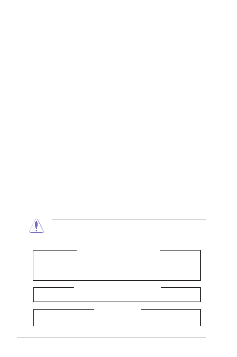
1.2 System overview
1
2
3
4
5
6
8
9
7
9
2
1.2.1 TS500-E5/PA4
Items
1. Central processing unit (CPU)
2. CPU heatsink and fan 7. ASUS Server management board (optional)
3. System memory 8. Single power supply
4. Hard disk drives 9. Rackmount rail kit (optional)
5. PIKE 1064E/1078 module (optional)
Items
6. Graphics card (optional)
ASUS TS500-E5 1-3
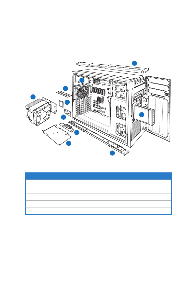
1.2.2 TS500-E5/RX8
1
2
3
4
5
6
7
8
8
Items Items
1. Central processing unit (CPU) 5. PIKE 1064E/1078 module (optional)
2. CPU heatsink and fan 6. ASUS Server management board (optional)
3. System memory 7. Redundant power supply module (optional)
4. Hard disk drives 8. Rackmount rail kit (optional)
Chapter 1: Product introduction1-4

1.3 Front panel features
1 2
!
Message LED
HDD access LED
Power LED
Optical drive
Empty 5.25-inch
bays
Floppy disk drive
4-bay HDD cage
4-bay HDD cage
(optional)
USB 2.0 ports
LAN1 LED
LAN2 LED
Security lock
Power button
Reset button
ASUS TS500-E5 1-5

1.4 Rear panel features
1.4.1 TS500-E5/PA4
PS/2 mouse port
PS/2 keyboard port
USB 2.0 ports
Serial port
VGA port
Gigabit LAN port 1
Gigabit LAN port 2
670W Single power supply
Chassis lock
Power connector
Chassis intrusion switch
120mm x 38mm
system fan
Expansion slots
Chapter 1: Product introduction1-6

1.4.2 TS500-E5/RX8
Redundant power
supply dummy*
PS/2 mouse port
PS/2 keyboard port
USB 2.0 ports
Serial port
VGA port
Gigabit LAN port 1
Gigabit LAN port 2
Power connector
Chassis lock
650W Redundant power supply
Chassis intrusion switch
120mm x 38mm
system fan
Expansion slots
* The second redundant power supply is an optional item.
ASUS TS500-E5 1-7

1.5 Systemspecications
Model Name TS500-E5/PA4 TS500-E5/RX8
Processor support
FSB
Core Logic
Memory
Storage
RAID support
NIC
Onboard Gfx
Expansion Slot
Power Supply
Dimension (HH x WW x DD)
Quad-Core Intel® Xeon® 5400 Series
Dual-Core Intel® Xeon® 5200 Series
1333 / 1066 MHz
Intel® 5100 MCH + Intel® ICH9R
6-DIMM support up to 24GB DDR2 667 / 533 Registered,
ECC
4 x Hot-swap HDD bays (upgradable to 8 HDD bays with
2nd HDD cage kit)
Default support:
S/W SATA RAID 0, 1, 5, 10 for Windows®
S/W SATA RAID 0, 1, 10 for Windows® and Linux
Option:
SAS/SATA RAID 0, 1, 1E support with optional PIKE
1064E module
H/W SAS/SATA RAID 0, 1, 5 , 6, 10, 50, 60 support with
optional PIKE 1078 module or LSI 8708ELP RAID card
2 x Broadcom® 5721 PCI-E GbE LAN
XGI Z9s VGA Controller / 32MB
Workstation Mode:
1 x PCI-E x16 slot (x16 link)
1 x PCI-E x8 slot (x8 link)
1 x PCI-E x8 slot (x4 link)
1 x PCI 32-bit/33MHz slot
Server Mode:
1 x PCI-E x16 slot (x8 link)
2 x PCI-E x8 slot (x8 link)
1 x PCI-E x8 slot (x4 link)
1 x PCI 32-bit/33MHz slot
670W Single Power Supply
450mm x 212mm x 550mm
Workstation Mode:
1 x PCI-E x16 slot (x16 link)
1 x PCI-E x8 slot (x8 link)
1 x PCI-E x8 slot (x4 link)
or (Auto disable if PIKE
slot is occupied)
1 x PCI 32-bit/33MHz slot
Server Mode:
1 x PCI-E x16 slot (x8 link)
2 x PCI-E x8 slot (x8 link)
1 x PCI-E x8 slot (x4 link)
or (Auto disable if PIKE
slot is occupied
1 x PCI 32-bit/33MHz slot
650W 1+1 Redundant
Power Supply*
*The second redundant power suplly is an optional item.
**Specicationsaresubjecttochangewithoutnotice.
Chapter 1: Product introduction1-8

Chapter 2
This chapter lists the key components
and optional accessories for the server
system.
Components
1-

2.1 Upgrading CPU and CPU heatsink
4
1
2
3
CPU2 CPU1
The ASUS TS500-E5 supports 1–2 Dual-core / Quad-core Intel® Xeon® 5400 /
5200 series processor.
Order P/N Description
90-S4Q0U0070T Quad Core Intel Xeon E5450 3.00G, FSB 1333, 12M L2
90-S4Q0U0060T Quad Core Intel Xeon E5440 2.83G, FSB 1333, 12M L2
90-S4Q0U0050T Quad Core Intel Xeon E5430 2.66G, FSB 1333, 12M L2
90-S4Q0U0040T Quad Core Intel Xeon E5420 2.50G, FSB 1333, 12M L2
90-S4Q0U0030T Quad Core Intel Xeon E5410 2.33G, FSB 1333, 12M L2
90-S4Q0U0020T Quad Core Intel Xeon E5405 2.00G, FSB 1333, 12M L2
90-S4Q0U0080T Dual Core Intel Xeon E5205 1.86G, FSB 1333, 12M L2
• If you install only one CPU, install the CPU to the
CPU2 socket only. The system will not boot and the
CPU warning LED will light up if a single CPU is
installed on the CPU1 socket.
• We recommend to install CPUs with the same frequency.
(with TS500-E5 Heatsink)
(with TS500-E5 Heatsink)
(with TS500-E5 Heatsink)
(with TS500-E5 Heatsink)
(with TS500-E5 Heatsink)
(with TS500-E5 Heatsink)
(with TS500-E5 Heatsink)
Chapter 2: Components2-2

2.2 Upgrading system memory
DIMM_A3
DIMM_B3
DIMM_A2
DIMM_B2
DIMM_A1
DIMM_B1
1
2
The motherboard comes with six (6) Double Data Rate 2 (DDR2) Dual Inline
Memory Modules (DIMM) sockets.
Recommendedmemorycongurations
DIMM_A3 DIMM_B3 DIMM_A2 DIMM_B2 DIMM_A1 DIMM_B1
- - - - 1 GB -
- - - - 1 GB 1 GB
- - 1 GB 1 GB 1 GB 1 GB
1 GB 1 GB 1 GB 1 GB 1 GB 1 GB
- - - - 2 GB -
- - - - 2 GB 2 GB
- - 2 GB 2 GB 2 GB 2 GB
2 GB 2 GB 2 GB 2 GB 2 GB 2 GB
- - - - 4 GB -
- - - - 4 GB 4 GB
- - 4 GB 4 GB 4 GB 4 GB
4 GB 4 GB 4 GB 4 GB 4 GB 4 GB
Order P/N Description
90-S000I0200T 1GB DDR2 667 ECC REG / ASUS
90-S000I0210T 2GB DDR2 667 ECC REG / ASUS
90-S000I0220T 4GB DDR2 667 ECC REG / ASUS
ASUS TS500-E5 2-3

2.3 Upgrading hard disk drives
HDD1
HDD2
HDD3
HDD4
1
2
The system supports four hot-swap SATAII/SAS hard disk drives, which could be
upgraded to eight HDDs with the optional hard disk drive cage.
We recommend that you install identical drives of the same model and capacity
for RAID conguration.
Order P/N Description
SAS HDD
90-S000H0040 300GB, 3.5” SAS HDD / ASUS
90-S000H0030 146GB, 3.5” SAS HDD / ASUS
90-S000H0020 73GB, 3.5” SAS HDD / ASUS
SATAII HDD
90-S000H5500T 1TB, 3.5” SATAII HDD / ASUS
90-S000H5400 750GB, 3.5” SATAII HDD / ASUS
90-S000H5300 500GB, 3.5” SATAII HDD / ASUS
90-S000H5000 250GB, 3.5” SATAII HDD / ASUS
Chapter 2: Components2-4

2.4 Upgrading hard disk drive cage
With the optional hard disk drive cage, the system could be upgraded up to eight
hot-swap SATAII/SAS hard disk drives.
Order P/N Description
90-S4R0H000T Cage Kit, SAS/SATA HDD Cage Kit (including Cage/Backplane/Cables)
ASUS TS500-E5 2-5

A
C
4
9
9
3
2
1
8
7
6
5
10
10
11
12
11
12
4
3
2
1
7
6
5
A
B
B
13
13
D
5
6
7
4
3
2
1
4
3
2
1
8
7
6
5
2.5 Installing ASUS PIKE 1064E module
The ASUS PIKE 1064E module allows users to create RAID 0, 1 and 1E from SAS
hard disk drives connected to the SAS connectors on the motherboard.
A. Insert the PIKE module into the PIKE card slot.
B. Connect the SAS cables to the SAS connectors on the motherboard and SATAII/SAS
backplane board*.
* Use the SAS1–4 connectors on the motherboard when installing PIKE 1064E module.
Order P/N Description
90-C1SCM0-00UAY00Z ASUS PIKE 1064E 4-port SAS Module (Support Integrated
RAID 0, 1, 1E)
Chapter 2: Components2-6

2.6 Installing ASUS PIKE 1078 module
A
C
4
9
9
3
2
1
8
7
6
5
10
10
11
12
11
12
B
13
13
D
4
3
2
1
8
7
6
5
The ASUS PIKE 1078 module allows users to create RAID 0, 1, 5, 6, 10, 50 and 60
from SAS hard disk drives connected to the SAS connectors on the motherboard.
A. Insert the PIKE module into the PIKE card slot.
B. Connect the SAS cables to the SAS connectors on the motherboard and SATAII/SAS
backplane board*.
C. Install the iButton**.
D. Ensure that the jumper caps are placed on pins 1–2 of the IBTN_SEL1 jumper.
* The connectors 9–12 are used for transferring SGPIO signals. Ensure to connect the
connectors 9 between the two backplanes when installing the second HDD cage. Refer to
user manual for details.
** PIKE 1078 module won’t function if the iButton is not installed.
Order P/N Description
90-C1SCN5-00UAY10Z ASUS PIKE 1078 8-port SAS RAID Module (Support Hardware
RAID 0, 1, 5, 6, 10, 50, 60)
ASUS TS500-E5 2-7

2.7 Installing ASUS Server Management
30 - 45
O
Board
ASMB3-SOL PLUS
ASUS Server Management Board is an Intelligent Platform Management Interface
(IPMI) 2.0-compliant board that allows users to monitor, control and manage a
remote server from the local or central server in local area network (LAN).
Order P/N Description
90-C1SCT5-00UAN00Z ASMB3-SOL PLUS IPMI 2.0 Module
Use the LAN1 port for server management.
Chapter 2: Components2-8

2.8 Upgrading graphics card
1
2
3
4
Contact local distributors for workstation SKU.
ASUS TS500-E5 2-9

2.9 Upgrading power supply unit
Order P/N Description
90-S4QPW0010T 650W Redundant Power Supply Module
Remove the dummy power supply module before installing the second
redundant power supply.
Chapter 2: Components2-10

2.10 Rackmount rail kit
Order P/N Description
90-S00SP0020T Rail Kit (Ball Bearing) for TS500-E5 Series
ASUS TS500-E5 2-11

2.11 OS support list
OS support list
Windows® Server 2003 R2 Enterprise 32-bit
Windows® Server 2003 R2 Enterprise 64-bit
RedHat® Enterprise Linux 32-bit
RedHat® Enterprise Linux 64-bit
SuSE® Linux Enterprise Server 32-bit
SuSE® Linux Enterprise Server 64-bit
Order P/N Description
90-S00SW7120T OS, Microsoft® Windows® Server 2003 R2 Standard 1-4 CPU, 5
90-S00SW7130T OS, Microsoft® Windows® Small Business Server 2003 R2 STD
CAL (32bit) (Traditional Chinese)
1-2 CPU, 5 CAL (32bit) (Chinese)
Chapter 2: Components2-12
 Loading...