

ASUS TS300-E3A User Manual
TS300-E3
®®
®
IntelIntel
Intel
IntelIntel
Pedestal/5U Rackmount Pedestal/5U Rackmount
Pedestal/5U Rackmount
Pedestal/5U Rackmount Pedestal/5U Rackmount
®®
Pentium Pentium
Pentium
Pentium Pentium
®®
®
®®
4/Pentium 4/Pentium
4/Pentium
4/Pentium 4/Pentium
ServerServer
Server
ServerServer
®®
®
®®
D LGA775 D LGA775
D LGA775
D LGA775 D LGA775
1066/800 MHz Front Side Bus

E2198E2198
E2198
E2198E2198
First Edition V1First Edition V1
First Edition V1
First Edition V1First Edition V1
August 2005August 2005
August 2005
August 2005August 2005
Copyright © 2005 ASUSTeK COMPUTER INC. All Rights Reserved.Copyright © 2005 ASUSTeK COMPUTER INC. All Rights Reserved.
Copyright © 2005 ASUSTeK COMPUTER INC. All Rights Reserved.
Copyright © 2005 ASUSTeK COMPUTER INC. All Rights Reserved.Copyright © 2005 ASUSTeK COMPUTER INC. All Rights Reserved.
No part of this manual, including the products and software described in it, may be reproduced,
transmitted, transcribed, stored in a retrieval system, or translated into any language in any form
or by any means, except documentation kept by the purchaser for backup purposes, without the
express written permission of ASUSTeK COMPUTER INC. (“ASUS”).
ASUS provides this manual “as is” without warranty of any kind, either express or implied,
including but not limited to the implied warranties or conditions of merchantability or fitness for
a particular purpose. In no event shall ASUS, its directors, officers, employees, or agents be liable
for any indirect, special, incidental, or consequential damages (including damages for loss of
profits, loss of business, loss of use or data, interruption of business and the like), even if ASUS
has been advised of the possibility of such damages arising from any defect or error in this
manual or product.
Specifications and information contained in this manual ae furnished for informational use only,
and are subject to change at any time without notice, and should not be construed as a
commitment by ASUS. ASUS assumes no responsibility or liability for any errors or inaccuracies
that may appear in this manual, including the products and software described in it.
Product warranty or service will not be extended if: (1) the product is repaired, modified or
altered, unless such repair, modification of alteration is authorized in writing by ASUS; or (2) the
serial number of the product is defaced or missing.
Products and corporate names appearing in this manual may or may not be registered
trademarks or copyrights of their respective companies, and are used only for identification or
explanation and to the owners’ benefit, without intent to infringe.
iiii
ii
iiii

Contents
Notices ............................................................................................... vii
Safety information ............................................................................ viii
About this guide ................................................................................. ix
Chapter 1: Product introductionChapter 1: Product introduction
Chapter 1: Product introduction
Chapter 1: Product introductionChapter 1: Product introduction
1.1 System package contents .................................................... 1-2
1.2 System specifications .......................................................... 1-4
1.3 Front panel features ............................................................. 1-5
1.4 Rear panel features .............................................................. 1-6
1.5 Internal features ................................................................... 1-7
1.6 LED information .................................................................... 1-9
Chapter 2: Hardware setupChapter 2: Hardware setup
Chapter 2: Hardware setup
Chapter 2: Hardware setupChapter 2: Hardware setup
2.1 Chassis cover ....................................................................... 2-2
2.1.1 Removing the side cover ........................................ 2-2
2.1.2 Reinstalling the side cover ...................................... 2-3
2.2 Motherboard overview .......................................................... 2-4
2.3 Central Processing Unit (CPU) .............................................. 2-5
2.3.1 Installing the CPU.................................................... 2-5
2.3.2 Installing the CPU heatsink and airduct assembly .. 2-8
2.4 System memory ................................................................. 2-10
2.4.1 Overview ............................................................... 2-10
2.4.2 Memory configurations ......................................... 2-10
2.4.3 Installing a DIMM ................................................... 2-11
2.4.4 Removing a DIMM ................................................. 2-11
2.5 Front panel assembly ......................................................... 2-12
2.5.1 Removing the front panel assembly ..................... 2-12
2.5.2 Reinstalling the front panel assembly ................... 2-14
2.6 5.25-inch drives ................................................................. 2-15
2.7 Hard disk drives ..................................................................2-18
2.7.1 Installing a hot-swap SATA/SCSI HDD .................. 2-18
2.7.2 Installing an HDD dummy cover ............................ 2-20
2.8 Expansion cards .................................................................. 2-21
2.8.1 Installing an expansion card .................................. 2-21
2.8.2 Removing an expansion card ................................ 2-22
iiiiii
iii
iiiiii

Contents
2.9 Cable connections .............................................................. 2-23
2.9.1 Motherboard connections ..................................... 2-23
2.9.2 SATA backplane connections ............................... 2-24
2.9.3 SCSI backplane connections ................................. 2-27
2.10 Removable components ..................................................... 2-30
2.10.1 Chassis fan ........................................................... 2-30
2.10.2 HDD blower ........................................................... 2-32
2.10.3 SATA/SCSI backplane ........................................... 2-35
2.10.4 Floppy disk drive ................................................... 2-37
2.10.5 Front I/O board .................................................... 2-39
2.10.6 Chassis footpads and roller wheels ...................... 2-41
2.10.7 Power supply unit ................................................. 2-43
Chapter 3:Chapter 3:
Chapter 3:
Chapter 3:Chapter 3:
Preparing the system for rack mounting ......................................... 3-2
Chapter 4:Chapter 4:
Chapter 4:
Chapter 4:Chapter 4:
4.1 Motherboard layouts ............................................................ 4-2
4.2 Jumpers ................................................................................ 4-5
4.3 Internal connectors ............................................................ 4-10
Chapter 5:Chapter 5:
Chapter 5:
Chapter 5:Chapter 5:
5.1 Managing and updating your BIOS ........................................ 5-2
5.1.1 Creating a bootable floppy disk .............................. 5-2
5.1.2 AFUDOS utility ........................................................ 5-3
5.1.3 ASUS CrashFree BIOS 2 utility ................................ 5-6
5.1.4 ASUS Update utility ................................................ 5-8
5.2 BIOS setup program ........................................................... 5-11
5.2.1 BIOS menu screen ................................................. 5-12
5.2.2 Menu bar ............................................................... 5-12
Installation optionInstallation option
Installation option
Installation optionInstallation option
Motherboard infoMotherboard info
Motherboard info
Motherboard infoMotherboard info
BIOS informationBIOS information
BIOS information
BIOS informationBIOS information
iviv
iv
iviv
5.2.3 Navigation keys .................................................... 5-12
5.2.4 Menu items ........................................................... 5-13
5.2.5 Sub-menu items ................................................... 5-13
5.2.6 Configuration fields .............................................. 5-13
5.2.7 Pop-up window ..................................................... 5-13
5.2.8 Scroll bar .............................................................. 5-13
5.2.9 General help .......................................................... 5-13

Contents
5.3 Main menu .......................................................................... 5-14
5.3.1 System Time .........................................................5-14
5.3.2 System Date ......................................................... 5-14
5.3.3 Legacy Diskette A ................................................5-14
5.3.4 IDE Configuration .................................................. 5-15
5.3.5 Primary/Secondary/Third IDE Master/Slave .........5-16
5.3.6 System Information ..............................................5-18
5.4 Advanced menu .................................................................. 5-19
5.4.1 MPS Configuration ................................................ 5-19
5.4.2 Remote Access Configuration .............................. 5-20
5.4.3 CPU Configuration ................................................. 5-21
5.4.4 Chipset Configuration ........................................... 5-23
5.4.5 Onboard Devices Configuration ............................5-27
5.4.6 PCI/PnP Configuration .......................................... 5-28
5.5 Power menu ........................................................................ 5-29
5.5.1 APM Configuration ................................................ 5-29
5.5.2 Hardware Monitor ................................................. 5-32
5.6 Boot menu .......................................................................... 5-34
5.6.1 Boot Device Priority .............................................. 5-34
5.6.2 Boot Settings Configuration ................................. 5-35
5.6.3 Security ................................................................ 5-36
5.7 Exit menu ........................................................................... 5-39
Chapter 6:Chapter 6:
Chapter 6:
Chapter 6:Chapter 6:
6.1 Setting up RAID .................................................................... 6-2
6.1.1 RAID definitions ...................................................... 6-2
6.1.2 Installing hard disk drives ....................................... 6-3
6.1.3 Setting the RAID item in BIOS ................................ 6-3
6.1.4 RAID configuration utilities ..................................... 6-4
6.2 LSI Logic Embedded SATA RAID Setup Utility ...................... 6-5
RAID ConfigurationRAID Configuration
RAID Configuration
RAID ConfigurationRAID Configuration
6.2.1 Creating a RAID 0 or RAID 1 set ............................. 6-6
6.2.2 Creating a RAID 10 set ......................................... 6-11
6.2.3 Adding or viewing a RAID configuration ............... 6-15
6.2.4 Initializing the logical drives .................................. 6-18
6.2.5 Rebuilding failed drives ......................................... 6-23
6.2.6 Checking the drives for data consistency ............ 6-25
vv
v
vv

Contents
6.2.7 Deleting a RAID configuration ............................... 6-28
6.2.8 Selecting the boot drive from a RAID set ............. 6-29
6.2.9 Enabling the WriteCache ...................................... 6-30
6.3 Global Array Manager ......................................................... 6-30
6.4 LSI Logic Configuration Utility
(for PS4 model only) .........
6-31
6.4.1 Boot Adapter List ................................................. 6-32
6.4.2 Global Properties .................................................. 6-33
6.4.3 Adapter Properties ............................................... 6-35
6.4.4 Creating a RAID 1 (Mirror) set .............................. 6-42
6.4.5 Creating a RAID 0 (Stripe) set .............................. 6-44
6.4.6 Running the Diagnostic Mode ............................... 6-44
6.4.7 Managing arrays ................................................... 6-46
Chapter 7:Chapter 7:
Chapter 7:
Chapter 7:Chapter 7:
Driver installationDriver installation
Driver installation
Driver installationDriver installation
7.1 RAID driver installation ......................................................... 7-2
7.1.1 Creating a RAID driver disk ..................................... 7-2
7.1.2 Installing the RAID controller driver ........................ 7-3
7.2 LAN driver installation ........................................................ 7-12
®
7.2.1 Windows
7.2.2 Red Hat
2000/2003 Server .............................. 7-12
®
Enterprise ver. 3.0 ................................ 7-13
7.3 VGA driver installation ........................................................ 7-14
®
7.3.1 Windows
7.3.2 Windows
7.3.3 Red Hat
2000 Server ........................................ 7-14
®
2003 Server ........................................ 7-15
®
Enterprise ver. 3.0 ................................ 7-15
7.4 Management applications and utilities installation ............. 7-16
7.4.1 Running the support CD ....................................... 7-16
7.4.2 Drivers menu ........................................................ 7-16
7.4.3 Management Software menu ................................ 7-17
7.4.4 Utilities menu ........................................................ 7-17
7.4.5 Contact information ............................................. 7-17
Appendix:Appendix:
Appendix:
Appendix:Appendix:
Reference informationReference information
Reference information
Reference informationReference information
A.1 450 W single power supply .................................................. A-2
A.1.1 General description ................................................. A-2
A.1.2 Specifications ......................................................... A-3
A.2 Simple fixes .......................................................................... A-4
vivi
vi
vivi
Notices
Federal Communications Commission StatementFederal Communications Commission Statement
Federal Communications Commission Statement
Federal Communications Commission StatementFederal Communications Commission Statement
This device complies with Part 15 of the FCC Rules. Operation is subject to
the following two conditions:
•
This device may not cause harmful interference, and
•
This device must accept any interference received including interference
that may cause undesired operation.
This equipment has been tested and found to comply with the limits for a
Class B digital device, pursuant to Part 15 of the FCC Rules. These limits
are designed to provide reasonable protection against harmful interference
in a residential installation. This equipment generates, uses and can radiate
radio frequency energy and, if not installed and used in accordance with
manufacturer’s instructions, may cause harmful interference to radio
communications. However, there is no guarantee that interference will not
occur in a particular installation. If this equipment does cause harmful
interference to radio or television reception, which can be determined by
turning the equipment off and on, the user is encouraged to try to correct
the interference by one or more of the following measures:
•
Reorient or relocate the receiving antenna.
•
Increase the separation between the equipment and receiver.
•
Connect the equipment to an outlet on a circuit different from that to
which the receiver is connected.
•
Consult the dealer or an experienced radio/TV technician for help.
WARNING!WARNING!
WARNING! The use of shielded cables for connection of the monitor to
WARNING!WARNING!
the graphics card is required to assure compliance with FCC regulations.
Changes or modifications to this unit not expressly approved by the
party responsible for compliance could void the user’s authority to
operate this equipment.
Canadian Department of Communications StatementCanadian Department of Communications Statement
Canadian Department of Communications Statement
Canadian Department of Communications StatementCanadian Department of Communications Statement
This digital apparatus does not exceed the Class B limits for radio noise
emissions from digital apparatus set out in the Radio Interference
Regulations of the Canadian Department of Communications.
This class B digital apparatus complies with Canadian ICES-003.This class B digital apparatus complies with Canadian ICES-003.
This class B digital apparatus complies with Canadian ICES-003.
This class B digital apparatus complies with Canadian ICES-003.This class B digital apparatus complies with Canadian ICES-003.
viivii
vii
viivii
Safety information
Electrical SafetyElectrical Safety
Electrical Safety
Electrical SafetyElectrical Safety
• Before installing or removing signal cables, ensure that the power cables
for the system unit and all attached devices are unplugged.
• To prevent electrical shock hazard, disconnect the power cable from the
electrical outlet before relocating the system.
• When adding or removing any additional devices to or from the system,
ensure that the power cables for the devices are unplugged before the
signal cables are connected. If possible, disconnect all power cables from
the existing system before you add a device.
• If the power supply is broken, do not try to fix it by yourself. Contact a
qualified service technician or your dealer.
Operation SafetyOperation Safety
Operation Safety
Operation SafetyOperation Safety
• Any mechanical operation on this server must be conducted by certified
or experienced engineers.
• Before operating the server, carefully read all the manuals included with
the server package.
• Before using the server, make sure all cables are correctly connected and
the power cables are not damaged. If any damage is detected, contact
your dealer as soon as possible.
• To avoid short circuits, keep paper clips, screws, and staples away from
connectors, slots, sockets and circuitry.
• Avoid dust, humidity, and temperature extremes. Place the server on a
stable surface.
This product is equipped with a three-wire power cable and plug for the
user’s safety. Use the power cable with a properly grounded electrical
outlet to avoid electrical shock.
Lithium-Ion Battery WarningLithium-Ion Battery Warning
Lithium-Ion Battery Warning
Lithium-Ion Battery WarningLithium-Ion Battery Warning
CAUTION!CAUTION!
CAUTION! Danger of explosion if battery is incorrectly replaced.
CAUTION!CAUTION!
Replace only with the same or equivalent type recommended by
the manufacturer. Dispose of used batteries according to the
manufacturer’s instructions.
CD-ROM Drive Safety WarningCD-ROM Drive Safety Warning
CD-ROM Drive Safety Warning
CD-ROM Drive Safety WarningCD-ROM Drive Safety Warning
viiiviii
viii
viiiviii
CLASS 1 LASER PRODUCTCLASS 1 LASER PRODUCT
CLASS 1 LASER PRODUCT
CLASS 1 LASER PRODUCTCLASS 1 LASER PRODUCT
Heavy SystemHeavy System
Heavy System
Heavy SystemHeavy System
CAUTION!CAUTION!
CAUTION! This server system is heavy. Ask for assistance when
CAUTION!CAUTION!
moving or carrying the system.

About this guide
AudienceAudience
Audience
AudienceAudience
This user guide is intended for system integrators and experienced users
with at least basic knowledge of configuring a server.
ContentsContents
Contents
ContentsContents
This guide contains the following parts:
1.1.
Chapter 1: Product IntroductionChapter 1: Product Introduction
1.
Chapter 1: Product Introduction
1.1.
Chapter 1: Product IntroductionChapter 1: Product Introduction
This chapter describes the general features of the server, including
sections on front panel and rear panel specifications.
2.2.
Chapter 2: Hardware setupChapter 2: Hardware setup
2.
Chapter 2: Hardware setup
2.2.
Chapter 2: Hardware setupChapter 2: Hardware setup
This chapter lists the hardware setup procedures that you have to
perform when installing or removing system components.
3.3.
Chapter 3: Installation optionsChapter 3: Installation options
3.
Chapter 3: Installation options
3.3.
Chapter 3: Installation optionsChapter 3: Installation options
This chapter describes how to install optional components into the
barebone server.
4.4.
Chapter 4: Motherboard informationChapter 4: Motherboard information
4.
Chapter 4: Motherboard information
4.4.
Chapter 4: Motherboard informationChapter 4: Motherboard information
This chapter gives information about the motherboard that comes
with the server. This chapter includes the motherboard layout, jumper
settings, and connector locations.
5.5.
Chapter 5: BIOS informationChapter 5: BIOS information
5.
Chapter 5: BIOS information
5.5.
Chapter 5: BIOS informationChapter 5: BIOS information
This chapter tells how to change system settings through the BIOS
Setup menus and describes the BIOS parameters.
6.6.
Chapter 6: RAID configurationChapter 6: RAID configuration
6.
Chapter 6: RAID configuration
6.6.
Chapter 6: RAID configurationChapter 6: RAID configuration
This chapter provides information on how toconfigure your hard disk
drives as RAID sets.
7.7.
Chapter 7: Driver installationChapter 7: Driver installation
7.
Chapter 7: Driver installation
7.7.
Chapter 7: Driver installationChapter 7: Driver installation
This chapter provides information on how to create a RAID set and
how to install the drivers for system components. This chapter also
describes the software applications that the barebone server
supports.
8.8.
Appendix: Reference informationAppendix: Reference information
8.
Appendix: Reference information
8.8.
Appendix: Reference informationAppendix: Reference information
This section provides information about the power supply unit and a
troubleshooting guide for solving common problems when using the
barebone server.
ixix
ix
ixix

ConventionsConventions
Conventions
ConventionsConventions
To make sure that you perform certain tasks properly, take note of the
following symbols used throughout this manual.
WARNING: WARNING:
WARNING: Information to prevent injury to yourself when trying
WARNING: WARNING:
to complete a task.
CAUTION:CAUTION:
CAUTION: Information to prevent damage to the components
CAUTION:CAUTION:
when trying to complete a task.
IMPORTANT: IMPORTANT:
IMPORTANT: Instructions that you MUST follow to complete a
IMPORTANT: IMPORTANT:
task.
NOTE: NOTE:
NOTE: Tips and information to aid in completing a task.
NOTE: NOTE:
ReferenceReference
Reference
ReferenceReference
Visit the ASUS websites worldwide that provide updated information for all
ASUS hardware and software products. Refer to the ASUS contact
information for details.
xx
x
xx
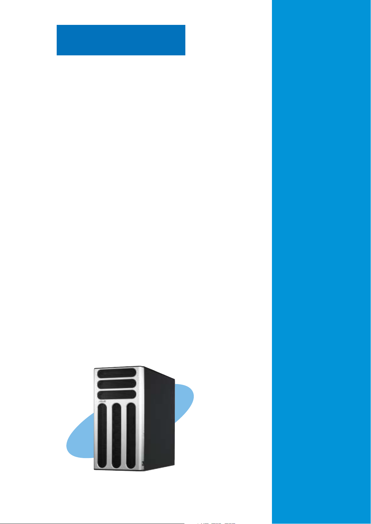
Chapter 1
This chapter describes the general
features of the barebone server,
including sections on the front
panel and rear panel specifications.
ASUS TS300-E3ASUS TS300-E3
ASUS TS300-E3
ASUS TS300-E3ASUS TS300-E3
Product introduction
1-1
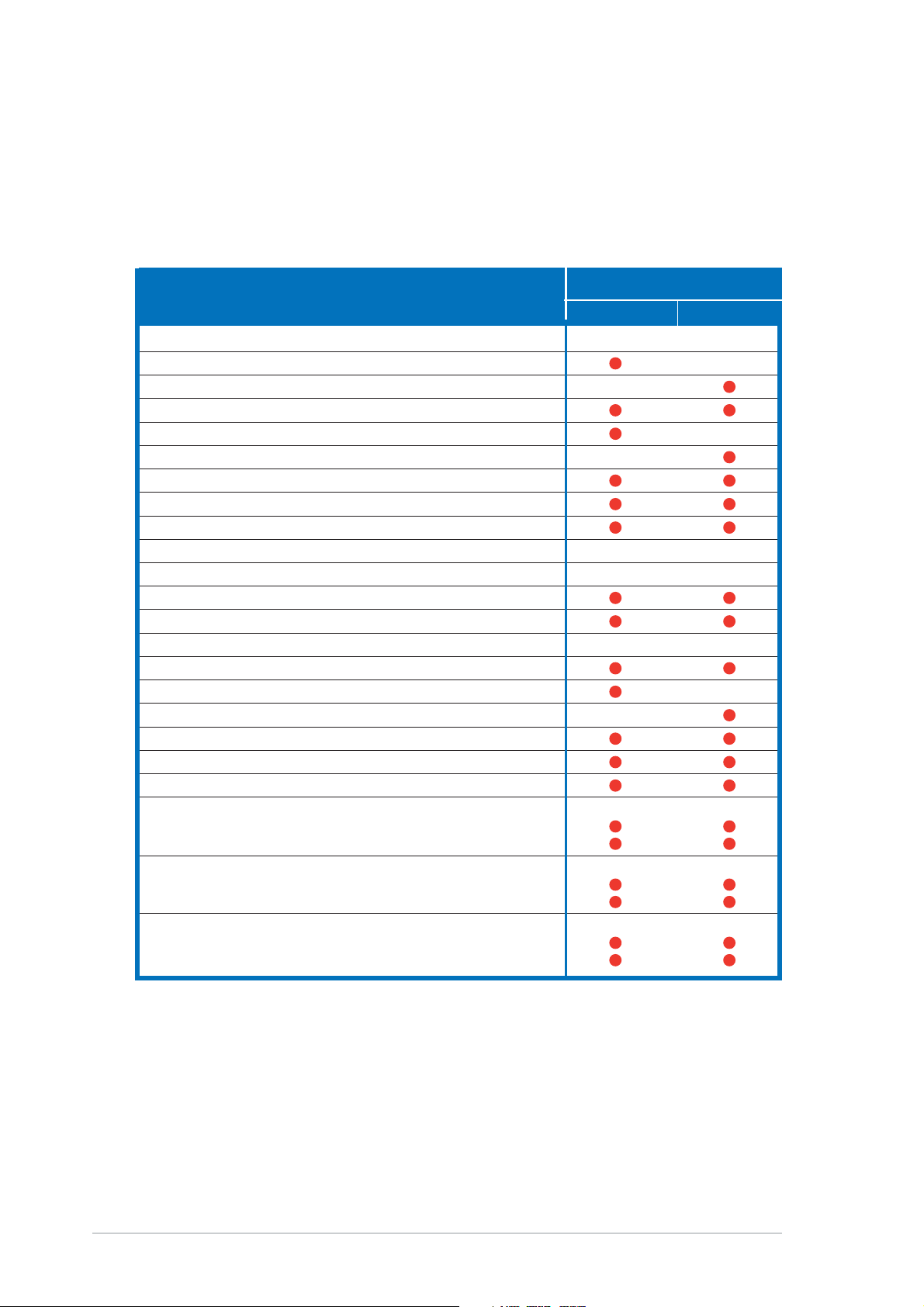
1.1 System package contents
Check your ASUS TS300-E3 package with the items on the following table.
The package contents vary for the following configurations:
PA4PA4
•
P A 4 (four hot-swap Serial ATA hard disk drives)
PA4PA4
PS4PS4
P S 4 (four hot-swap SCSI hard disk drives)
•
PS4PS4
ConfigurationsConfigurations
Configurations
ConfigurationsConfigurations
Item DescriptionItem Description
Item Description
Item DescriptionItem Description
ASUS TS300-E3 5U rackmount chassis with:
• ASUS P5MT motherboard
• ASUS P5MT/SCSI motherboard
• 450 W single power supply
• SATA backplane board
• SCSI backplane board
• Floppy disk drive
• 9 cm Blower
• 12 cm Chassis fan
• Hot-swap HDD trays (including HDD screws) 4 4
• Chassis roller wheels 4 4
• Front I/O board
• Dummy covers
Cables
• AC power cable
• SATA signal cables
• SCSI signal cables
• SMBus cable
System screws and cables
System keys ( 2 pcs.)
Bundled CDs
• TS300-E3 support CD with ASWM*
• Computer Associates® eTrust™ anti-virus CD
Documentation
• ASUS TS300-E3 user guide
• ASUS ASWM 2.0 user guide
Optional items
• 52x IDE CD-ROM or 16X DVD-ROM drive
• ASUS TS300-E3 rackmount rail kit
PA4PA4
PA4
PA4PA4
PS4PS4
PS4
PS4PS4
*ASUS System Web-based Management
1-21-2
1-2
1-21-2
Chapter 1: Product introductionChapter 1: Product introduction
Chapter 1: Product introduction
Chapter 1: Product introductionChapter 1: Product introduction
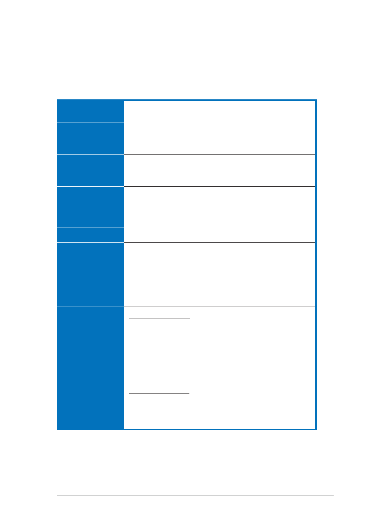
1.2 System specifications
The ASUS TS300-E3 is a barebone server system featuring the ASUS P5MT
Series motherboard. The server supports an Intel
processor in the 775-land package, and includes the latest technologies
through the chipsets embedded on the motherboard.
®
Pentium® 4/Pentium® D
ChassisChassis
Chassis
ChassisChassis
MotherboardMotherboard
Motherboard
MotherboardMotherboard
ChipsetChipset
Chipset
ChipsetChipset
ProcessorProcessor
Processor
ProcessorProcessor
Front Side BusFront Side Bus
Front Side Bus
Front Side BusFront Side Bus
MemoryMemory
Memory
MemoryMemory
Pedestal or rackmount 5U with removable front door bezel
and chassis foot stand or roller-wheels.
ASUS P5MT (PA4 model)
ASUS P5MT/SCSI (PS4 model)
ATX compatible form factor: 12 in x 9.6 in
Northbridge: Intel
®
E7230 Memory Controller Hub (MCH)
Southbridge: Intel® ICH7R
I/O Bridge: Intel® 6702 PXH
®
Pentium® 4/Intel® Pentium® D processor in the
Intel
775-land package with Extended Memory 64-bit
Technology (EM64T)
Supports Dual Core technology
1066/800/533 MHz
Dual-channel memory architecture
4 x 240-pin DIMM sockets support ECC/non-ECC
unbuffered 667/533 MHz DDR2 memory modules
Supports 256 MB up to 8 GB of system memory
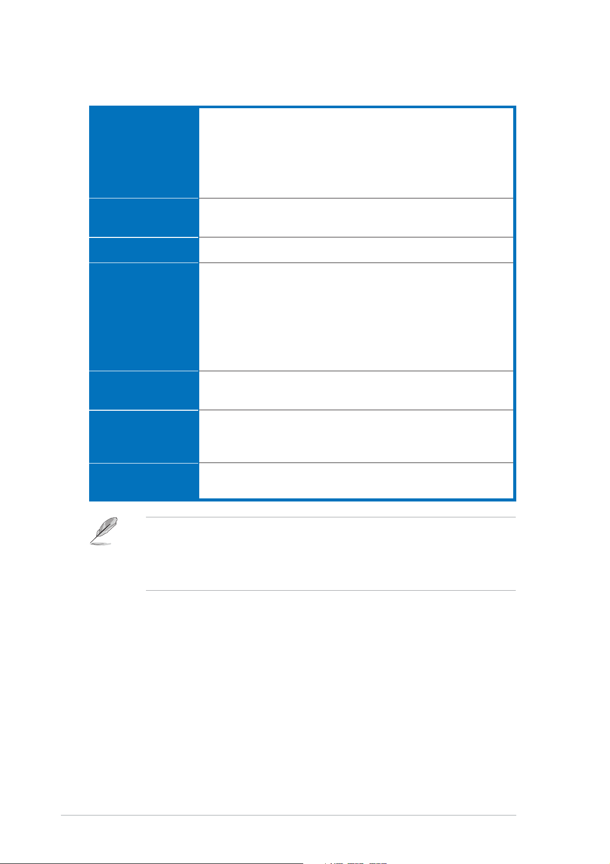
LANLAN
LAN
LANLAN
StorageStorage
Storage
StorageStorage
Dual Broadcom
®
BCM5721 Gigabit LAN controllers
- PCI Express 1.0a specifications compliant
For PA4 model only
Intel® ICH7R Southbridge supports:
- 4 x Serial ATA 3 Gb/s hard disk drives
- RAID 0, RAID 1, RAID 0+1, and RAID 5 (with limited OS
support) configuration
- Intel® Matrix Storage Technology
- LSI Logic Embedded SATA RAID controller (RAID 0,
RAID 1, RAID 10)
For PS4 model only
LSI1020A PCI-X SCSI controller supports:
- 1 x Ultra 320 SCSI channel with RAID 0, RAID 1, and
RAID1E configuration
- Zero-Channel RAID
(continued on the next page)
(optional)
ASUS TS300-E3ASUS TS300-E3
ASUS TS300-E3
ASUS TS300-E3ASUS TS300-E3
1-31-3
1-3
1-31-3
1.2 System specifications
ExpansionExpansion
Expansion
ExpansionExpansion
slotsslots
slots
slotsslots
Drive baysDrive bays
Drive bays
Drive baysDrive bays
Front panelFront panel
Front panel
Front panelFront panel
Rear panelRear panel
Rear panel
Rear panelRear panel
ManagementManagement
Management
ManagementManagement
1 x PCI 33 MHz/32-bit/5V (PCI 2.3)
1 x PCI-X 100 MHz/64-bit slot (PCI-X 1.0)
1 x PCI-X 100 MHz/64-bit slot (supports ZCR, PCI-X 1.0)*
(colored green on PS4 model)
1 x PCI Express™ x16 slot (x8 Link)**
1 x Mini-PCI socket for the ASUS Server Management Board
1 x 3.25-inch FDD bay
3 x 5.25-inch drive bays
2 x USB 2.0 ports
1 x Serial port
1 x Parallel port
1 x PS/2 keyboard port
1 x PS/2 mouse port
2 x LAN (RJ-45) ports
2 x USB 2.0 ports
1 x VGA port
ASUS Server Web-based Management (ASWM) 2.0
ASUS Server Monitoring Agent (ASMA)
HardwareHardware
Hardware
HardwareHardware
monitorsmonitors
monitors
monitorsmonitors
Power supplyPower supply
Power supply
Power supplyPower supply
* Only PS4 model supports Zero Channel RAID (ZCR).
** If you install a PCI Express VGA card, the link speed downgrades to
x1 due to chipset limitation. This limitation applies only to VGA
cards.
Voltage, temperature, CPU and memory utilization, storage
capacity, and fan speed monitoring
Automatic Server Restart (ASR) feature
450 W single power supply
(with 24-pin and 4-pin power plugs)
1-41-4
1-4
1-41-4
Chapter 1: Product introductionChapter 1: Product introduction
Chapter 1: Product introduction
Chapter 1: Product introductionChapter 1: Product introduction
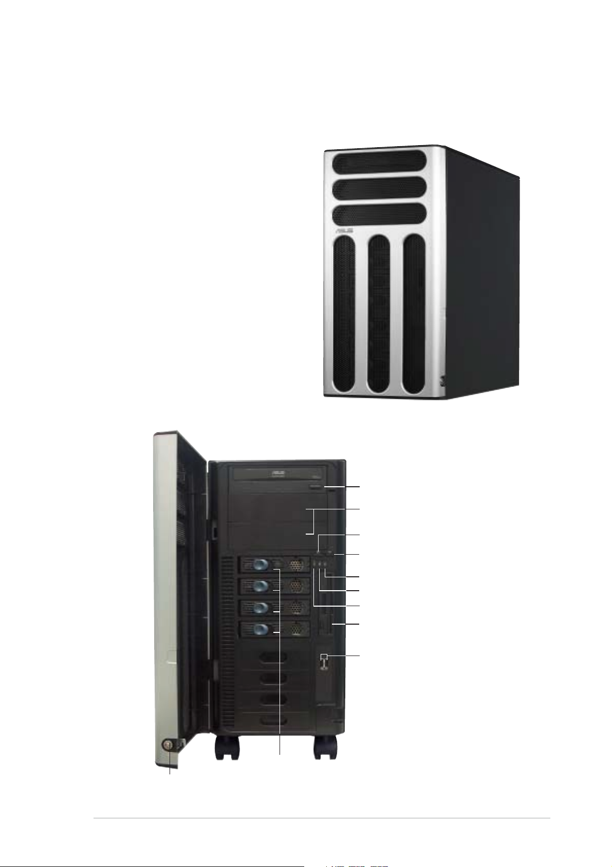
1.3 Front panel features
The TS300-E3 chassis displays a stylish front bezel with lock. The bezel
covers the system components on the front panel and serves as security.
Open the bezel to access the front panel components.
The drive bays, power and reset
buttons, LED indicators, CD-ROM
drive, floppy drive, and USB 2.0
ports are located on the front panel.
For future installation of 5.25-inch
devices, two drive bays are
available.
Security lockSecurity lock
Security lock
Security lockSecurity lock
Drive baysDrive bays
Drive bays
Drive baysDrive bays
CC
D-ROM driveD-ROM drive
C
D-ROM drive
CC
D-ROM driveD-ROM drive
Empty 5.25-inch baysEmpty 5.25-inch bays
Empty 5.25-inch bays
Empty 5.25-inch baysEmpty 5.25-inch bays
Power buttonPower button
Power button
Power buttonPower button
Reset buttonReset button
Reset button
Reset buttonReset button
Message LEDMessage LED
Message LED
Message LEDMessage LED
HDD access LEDHDD access LED
HDD access LED
HDD access LEDHDD access LED
Power LEDPower LED
Power LED
Power LEDPower LED
Floppy disk driveFloppy disk drive
Floppy disk drive
Floppy disk driveFloppy disk drive
USB 2.0 portsUSB 2.0 ports
USB 2.0 ports
USB 2.0 portsUSB 2.0 ports
ASUS TS300-E3ASUS TS300-E3
ASUS TS300-E3
ASUS TS300-E3ASUS TS300-E3
1-51-5
1-5
1-51-5
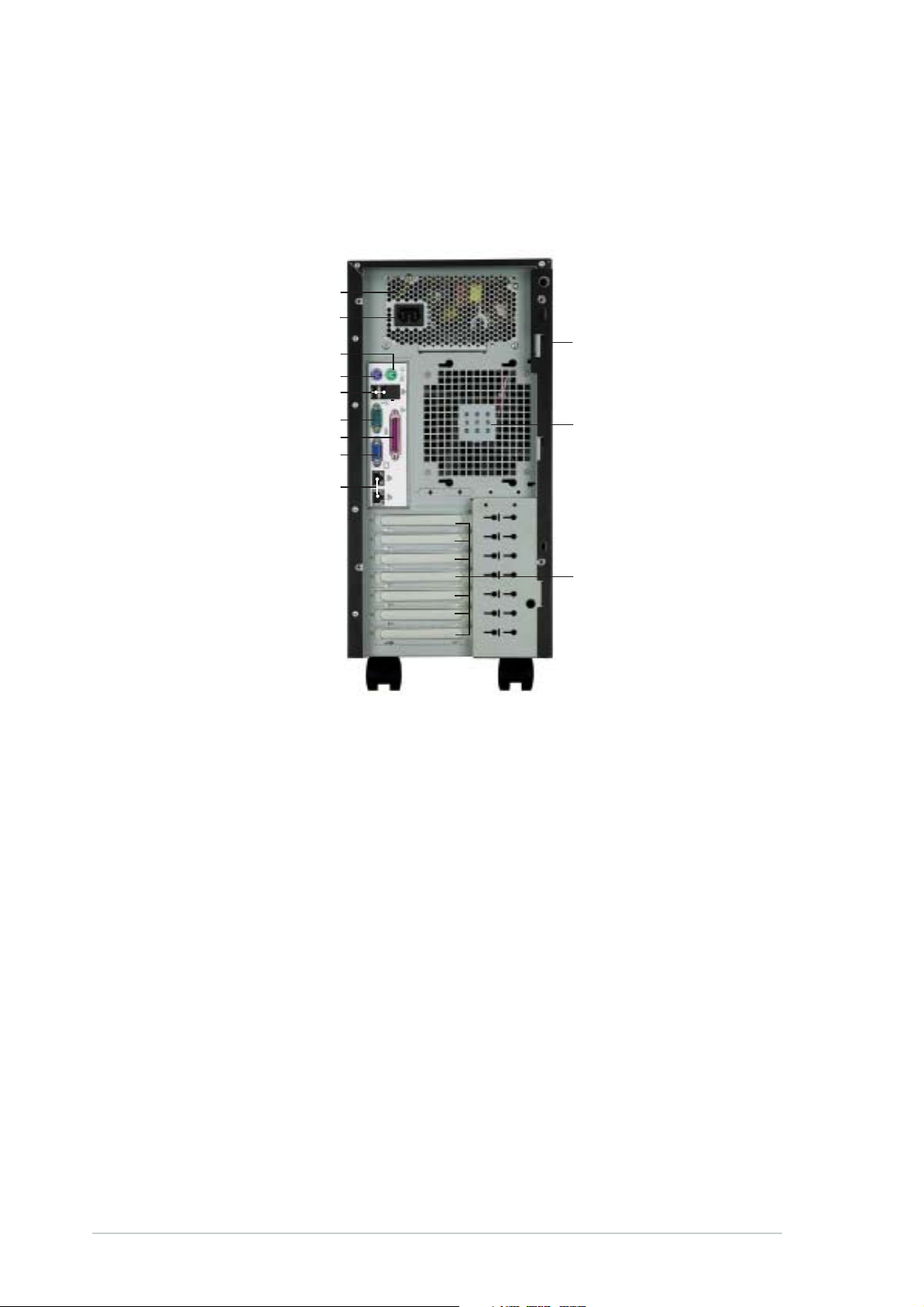
1.4 Rear panel features
The rear panel includes a slot for the motherboard rear I/O ports,
expansion slots, a chassis lock and intrusion switch, a vent for the system
fan, and power supply module.
Power supply modulePower supply module
Power supply module
Power supply modulePower supply module
Power Power
Power
Power Power
PS/2 mouse portPS/2 mouse port
PS/2 mouse port
PS/2 mouse portPS/2 mouse port
PS/2 keyboard portPS/2 keyboard port
PS/2 keyboard port
PS/2 keyboard portPS/2 keyboard port
Gigabit LAN portsGigabit LAN ports
Gigabit LAN ports
Gigabit LAN portsGigabit LAN ports
connectorconnector
connector
connectorconnector
USB 2.0 portsUSB 2.0 ports
USB 2.0 ports
USB 2.0 portsUSB 2.0 ports
Serial portSerial port
Serial port
Serial portSerial port
Parallel portParallel port
Parallel port
Parallel portParallel port
VGA portVGA port
VGA port
VGA portVGA port
Chassis intrusionChassis intrusion
Chassis intrusion
Chassis intrusionChassis intrusion
switchswitch
switch
switchswitch
12 cm system fan12 cm system fan
12 cm system fan
12 cm system fan12 cm system fan
Expansion slotsExpansion slots
Expansion slots
Expansion slotsExpansion slots
1-61-6
1-6
1-61-6
Chapter 1: Product introductionChapter 1: Product introduction
Chapter 1: Product introduction
Chapter 1: Product introductionChapter 1: Product introduction
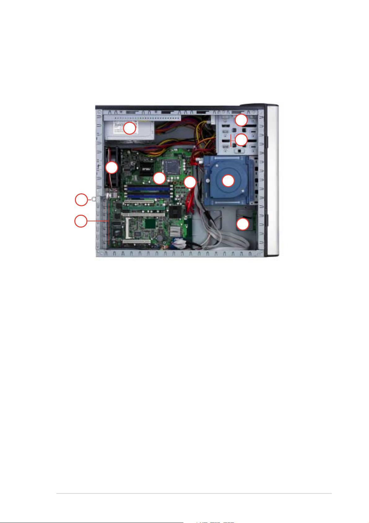
1.5 Internal features
The barebone server system includes the basic components as shown. The
photo below shows the TS300-E3 with the hard disk drive blower installed.
The HDD blower circulates cool air within the system.
PA4 (4 hot-swap SATA configuration)PA4 (4 hot-swap SATA configuration)
PA4 (4 hot-swap SATA configuration)
PA4 (4 hot-swap SATA configuration)PA4 (4 hot-swap SATA configuration)
66
6
66
11
1
11
•
77
7
77
•
22
2
22
33
3
33
44
4
44
55
5
55
•
•
•
•
•
•
•
1010
10
1010
88
8
88
99
9
99
1. Power supply unit
2. Chassis fan
3. ASUS P5MT motherboard
4. Chassis intrusion switch
5. Expansion card locks
6. Optical drive
7. 2 x 5.25-inch drive bays
8. HDD blower (HDD drive cage inside)
9. Front I/0 board
10. SATA backplane
ASUS TS300-E3ASUS TS300-E3
ASUS TS300-E3
ASUS TS300-E3ASUS TS300-E3
1-71-7
1-7
1-71-7
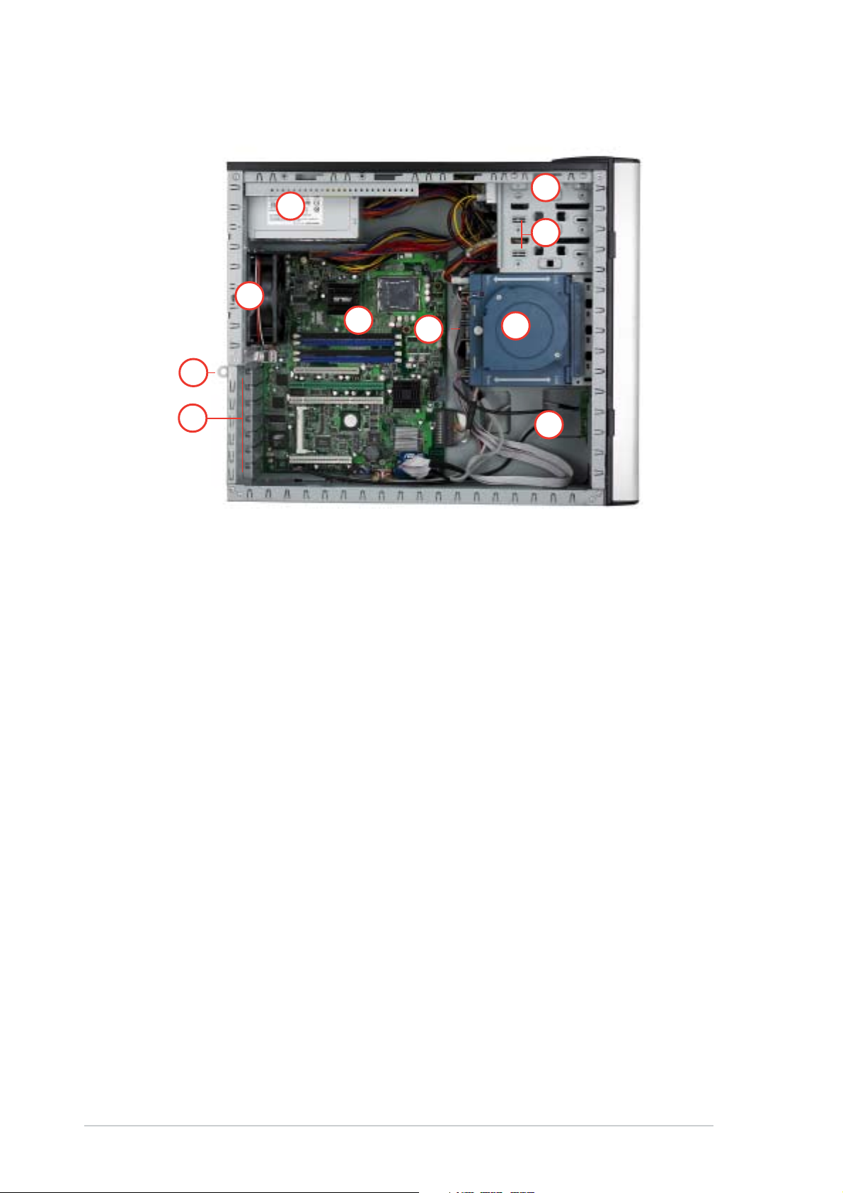
PS4 (4 hot-swap SCSI configuration) PS4 (4 hot-swap SCSI configuration)
PS4 (4 hot-swap SCSI configuration)
PS4 (4 hot-swap SCSI configuration) PS4 (4 hot-swap SCSI configuration)
66
6
66
11
1
11
•
77
7
77
•
22
2
22
33
3
33
44
4
44
55
5
55
•
•
•
•
•
•
•
1010
10
1010
88
8
88
99
9
99
1. Power supply unit
2. Chassis fan
3. ASUS P5MT/SCSI motherboard
4. Chassis intrusion switch
5. Expansion card locks
6. Optical drive
7. 2 x 5.25-inch drive bays
8. HDD blower (HDD drive cage inside)
9. Front I/0 board
10. SCSI backplane
1-81-8
1-8
1-81-8
Chapter 1: Product introductionChapter 1: Product introduction
Chapter 1: Product introduction
Chapter 1: Product introductionChapter 1: Product introduction
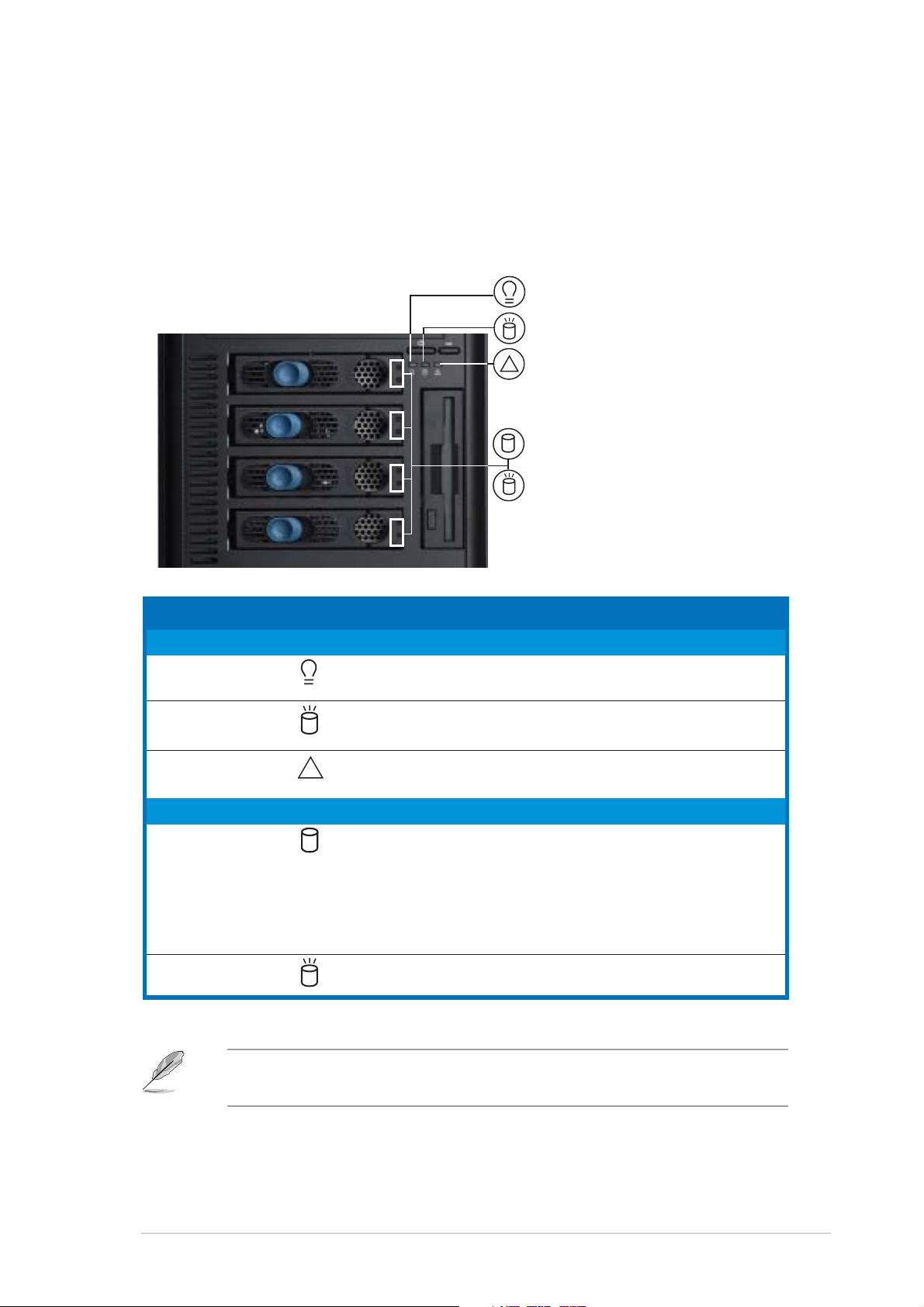
1.6 LED information
The barebone system comes with five LED indicators. Refer to the following
table for the LED status description.
System and HDD LEDSystem and HDD LED
System and HDD LED
System and HDD LEDSystem and HDD LED
Power LED (blue)Power LED (blue)
Power LED (blue)
Power LED (blue)Power LED (blue)
HDD Access LED (green)HDD Access LED (green)
HDD Access LED (green)
HDD Access LED (green)HDD Access LED (green)
Message LED (red)Message LED (red)
Message LED (red)
Message LED (red)Message LED (red)
!
Drive Status LED (green/red)Drive Status LED (green/red)
Drive Status LED (green/red)
Drive Status LED (green/red)Drive Status LED (green/red)
Drive Activity LED (green)Drive Activity LED (green)
Drive Activity LED (green)
Drive Activity LED (green)Drive Activity LED (green)
LEDLED
LED
LEDLED
SystemSystem
System
SystemSystem
Power LED ON System power ON
HDD Access LED OFF No activity
Message LED OFF System is normal; no incoming event
Hard disk drivesHard disk drives
Hard disk drives
Hard disk drivesHard disk drives
Drive Status LED Green Bridge board connected to backplane
Drive Activity LED Blinking Read/write data into the HDD
*SCSI Access Fault-Tolerant Enclosure (on PS4 model only)
IconIcon
Icon
IconIcon
!
Display statusDisplay status
Display status
Display statusDisplay status
Blinking System is in suspend mode
Blinking Read/write data into the HDD
Blinking ASMS indicates a HW monitor event
Red HDD failure
Green/Red - Blinking HDD rebuilding using the RAID card
DescriptionDescription
Description
DescriptionDescription
Installed HDD is in good condition
SAF-TE* function
The Power, HDD Access, and Message LEDs are visible even if the
system front bezel is closed.
ASUS TS300-E3ASUS TS300-E3
ASUS TS300-E3
ASUS TS300-E3ASUS TS300-E3
1-91-9
1-9
1-91-9

1-101-10
1-10
1-101-10
Chapter 1: Product introductionChapter 1: Product introduction
Chapter 1: Product introduction
Chapter 1: Product introductionChapter 1: Product introduction
Chapter 2
This chapter lists the hardware setup
procedures that you have to perform when
installing or removing system components.
ASUS TS300-E3ASUS TS300-E3
ASUS TS300-E3
ASUS TS300-E3ASUS TS300-E3
Hardware setup
2-1
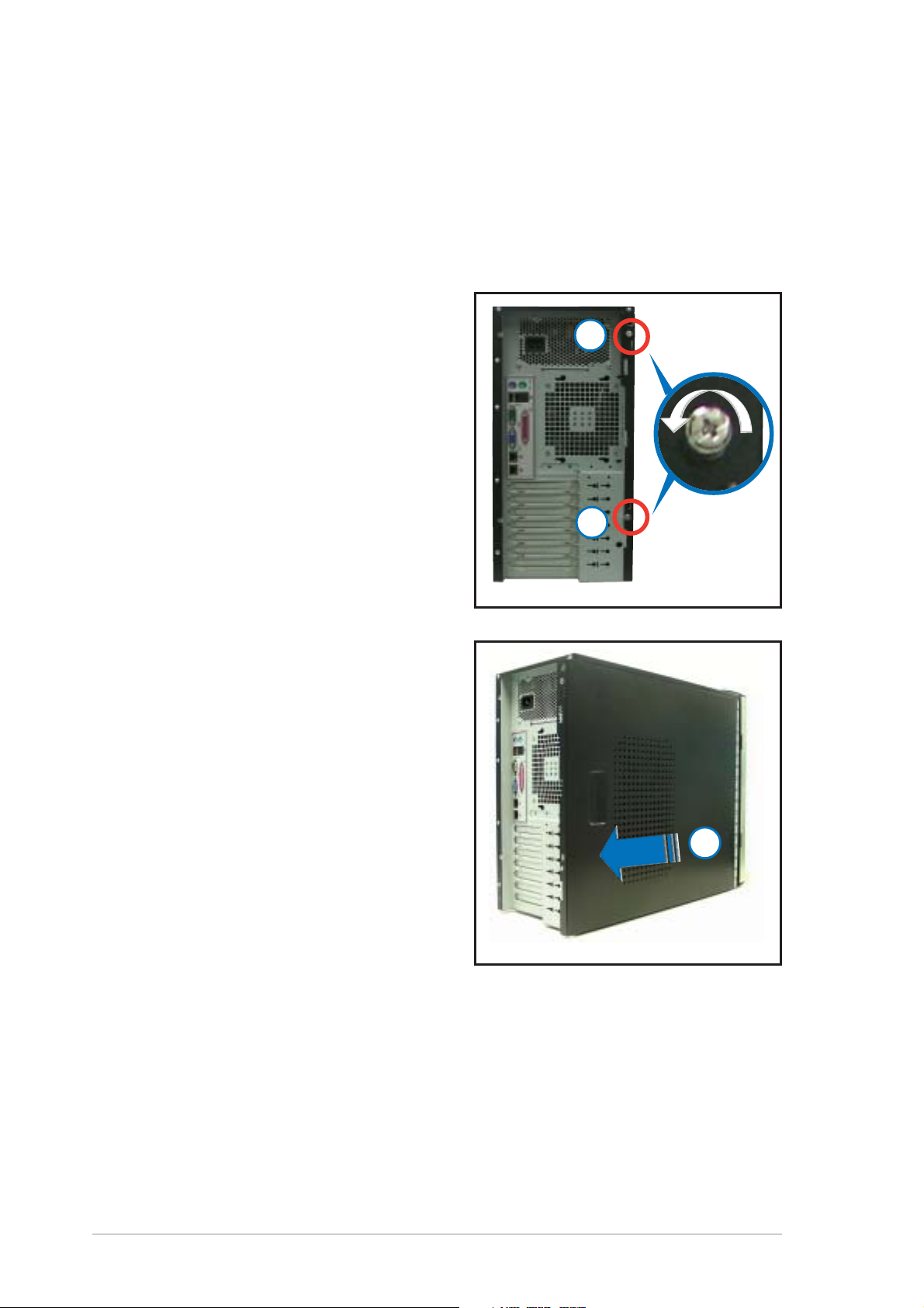
2.1 Chassis cover
The chassis features a “screwless design” that allows convenient assembly
and disassembly. You can simply push or slide mechanical bolts and locks to
remove the cover.
2.1.12.1.1
2.1.1
2.1.12.1.1
1. Remove the two screws that
secure the cover to the chassis.
2. Slide the side cover for about
half an inch toward the rear until
it is disengaged from the
chassis.
Removing the side coverRemoving the side cover
Removing the side cover
Removing the side coverRemoving the side cover
11
1
11
11
1
11
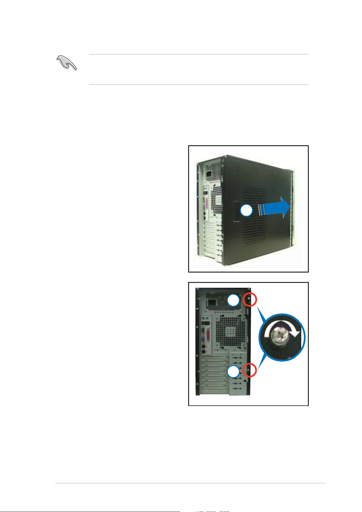
3. Carefully lift the cover and set it
aside.
22
2
22
Viewing the internal structureViewing the internal structure
Viewing the internal structure
Viewing the internal structureViewing the internal structure
Without the side cover, the internal structure and installed components of
the barebone server vary depending on the model you purchased. Refer to
section “1.5 Internal features” for the different model configurations.
Perform the procedures in the succeeding sections to install the CPU,
system memory, disk drives, and expansion cards; replace fans and power
supply; and connect the system cables.
2-22-2
2-2
2-22-2
Chapter 2: Hardware setupChapter 2: Hardware setup
Chapter 2: Hardware setup
Chapter 2: Hardware setupChapter 2: Hardware setup
You may need to remove some of the installed components to access
the DIMM sockets and internal connectors. Refer to section “2.10
Removable components” for instructions.
2.1.22.1.2
2.1.2
2.1.22.1.2
To reinstall the side cover:
1. Match and insert the upper
hooks and lower sliding edge of
the cover to the corresponding
chassis holes and edge.
2. Slide the cover toward the front
until it snaps in place.
3. Drive in the two screws you
removed earlier to secure the
side cover.
Reinstalling the side coverReinstalling the side cover
Reinstalling the side cover
Reinstalling the side coverReinstalling the side cover
33
3
33
22
2
22
ASUS TS300-E3ASUS TS300-E3
ASUS TS300-E3
ASUS TS300-E3ASUS TS300-E3
33
3
33
2-32-3
2-3
2-32-3
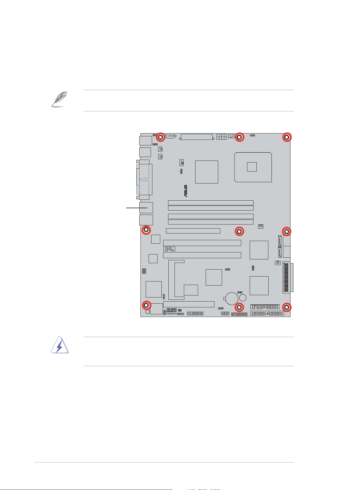
2.2 Motherboard overview
®
The barebone server comes with the P5MT (PA4 model) or P5MT/SCSI
(PS4 model) motherboard already installed. The motherboard is secured to
the chassis by nine (9) screws as indicated by the circles in the illustration
below.
Refer to “Chapter 4 Motherboard information” for detailed information
on the motherboard.
Place this side towardsPlace this side towards
Place this side towards
Place this side towardsPlace this side towards
the rear of the chassisthe rear of the chassis
the rear of the chassis
the rear of the chassisthe rear of the chassis
LAN2
Make sure to unplug the power cord before installing or removing any
motherboard component or connection. Failure to do so can cause you
physical injury and damage motherboard components.
2-42-4
2-4
2-42-4
Chapter 2: Hardware setupChapter 2: Hardware setup
Chapter 2: Hardware setup
Chapter 2: Hardware setupChapter 2: Hardware setup

2.3 Central Processing Unit (CPU)
®
The motherboard comes with a surface mount LGA775 socket designed for
the Intel® Pentium® 4 processor in the 775-land package
2.3.12.3.1
2.3.1
2.3.12.3.1
Installing the CPUInstalling the CPU
Installing the CPU
Installing the CPUInstalling the CPU
To install a CPU:
1. Locate the CPU socket on the motherboard.
LAN2
P5MT Series CPU Socket 775
Before installing the CPU, make sure that the cam box is facing towards
you and the load lever is on your left.
2. Press the load lever with your thumb (A), then move it to the left (B)
until it is released from the retention tab.
Retention tabRetention tab
Retention tab
Retention tabRetention tab
A
PnP capPnP cap
PnP cap
Load leverLoad lever
Load lever
Load leverLoad lever
B
This side of theThis side of the
This side of the
This side of theThis side of the
socket box shouldsocket box should
socket box should
socket box shouldsocket box should
face you.face you.
face you.
face you.face you.
To prevent damage to the socket pins, do not remove the PnP cap
unless you are installing a CPU.
PnP capPnP cap
ASUS TS300-E3ASUS TS300-E3
ASUS TS300-E3
ASUS TS300-E3ASUS TS300-E3
2-52-5
2-5
2-52-5
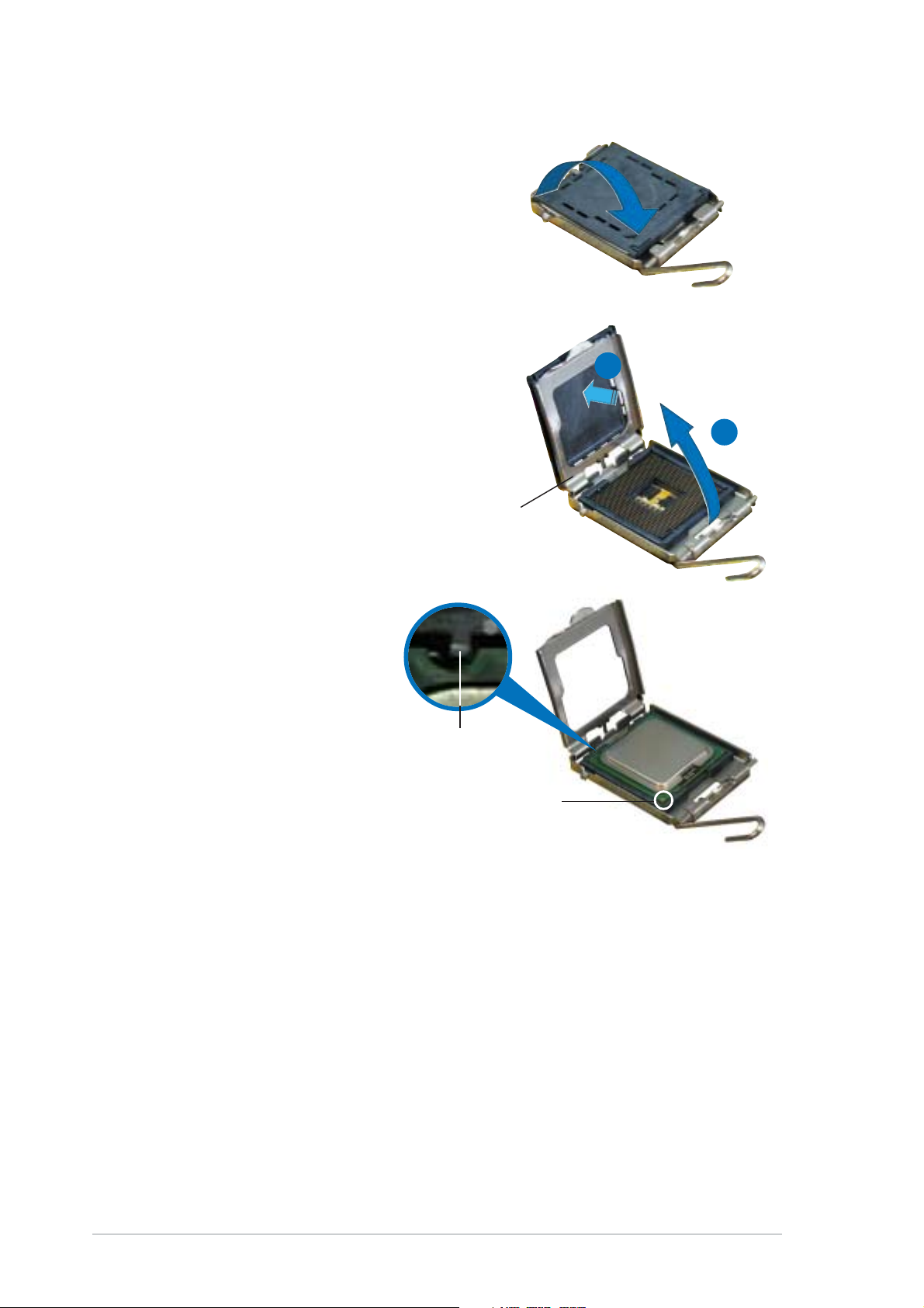
3. Lift the load lever in the
direction of the arrow to a 135º
angle.
4. Lift the load plate with your
thumb and forefinger to a 100º
angle (A), then push the PnP cap
from the load plate window to
remove (B).
Load plateLoad plate
Load plate
Load plateLoad plate
B
A
5. Position the CPU over
the socket, making sure
that the gold triangle is
on the bottom-left
corner of the socket.
The socket alignment
key should fit into the
CPU notch.
Alignment keyAlignment key
Alignment key
Alignment keyAlignment key
Gold triangle markGold triangle mark
Gold triangle mark
Gold triangle markGold triangle mark
2-62-6
2-6
2-62-6
Chapter 2: Hardware setupChapter 2: Hardware setup
Chapter 2: Hardware setup
Chapter 2: Hardware setupChapter 2: Hardware setup
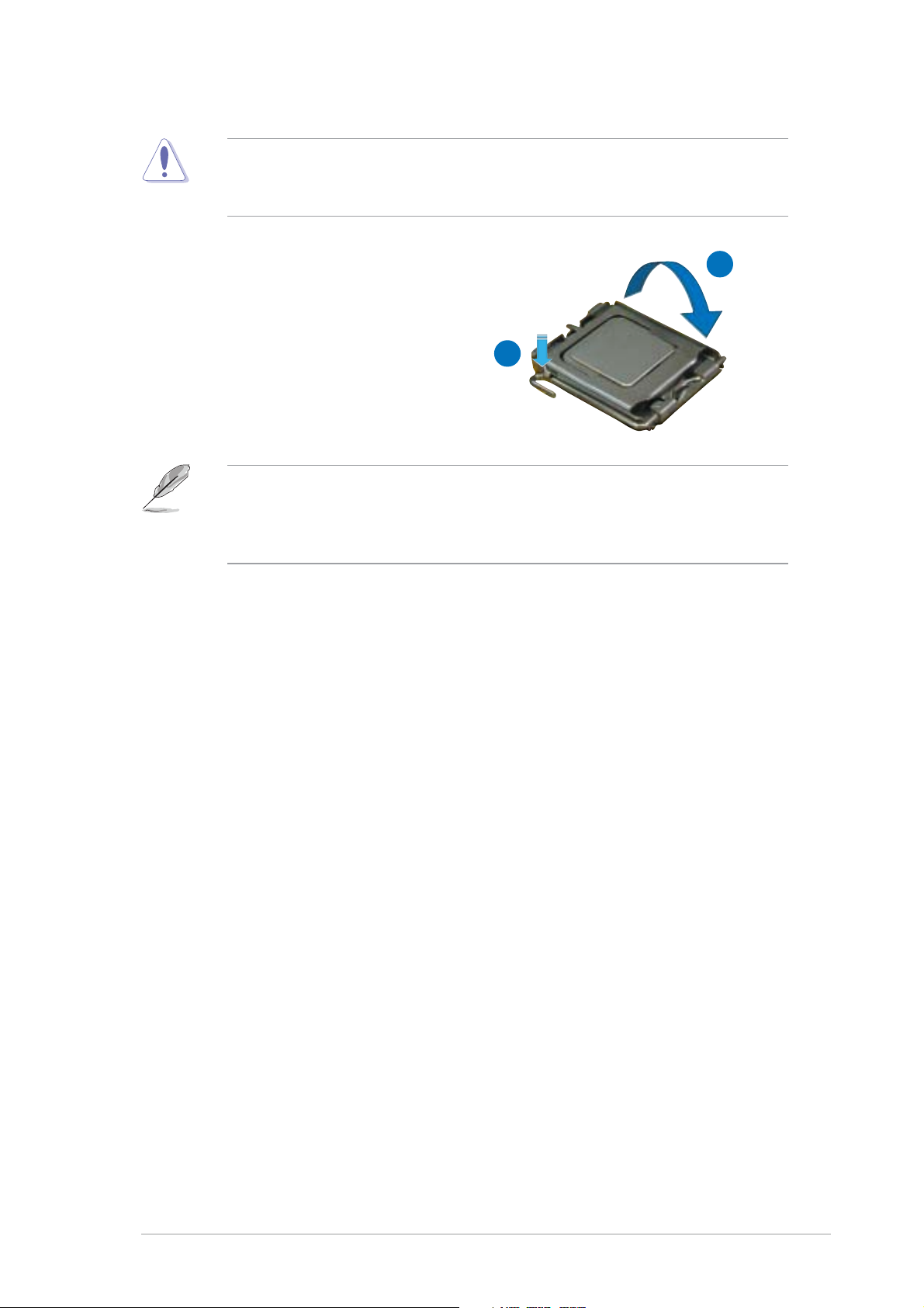
The CPU fits in only one correct orientation. DO NOT force the CPU into
the socket to prevent bending the connectors on the socket and
damaging the CPU!
6. Close the load plate (A), then
push the load lever (B) until
it snaps into the retention
tab.
The motherboard supports Intel® Pentium® 4 LGA775 processors with
the Intel® Enhanced Memory 64 Technology (EM64T), Enhanced Intel
SpeedStep® Technology (EIST), and Hyper-Threading Technology. Refer
to the Appendix for more information on these CPU features.
A
B
ASUS TS300-E3ASUS TS300-E3
ASUS TS300-E3
ASUS TS300-E3ASUS TS300-E3
2-72-7
2-7
2-72-7
2.3.22.3.2
2.3.2
2.3.22.3.2
The TS300-E3 comes with a proprietary CPU heatsink and airduct, which
come in separate boxes when you receive the package. You have to
assemble the CPU heatsink and airduct before installing to the
motherboard.
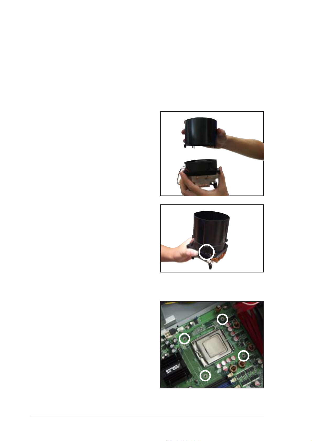
To assemble the CPU heatsink and airduct:
1. Align the airduct pegs to the fan
and heatsink holes.
Installing the CPU heatsink and airductInstalling the CPU heatsink and airduct
Installing the CPU heatsink and airduct
Installing the CPU heatsink and airductInstalling the CPU heatsink and airduct
assemblyassembly
assembly
assemblyassembly
2. Push down the airduct into the
holes to secure the assembly.
To install the CPU heatsink and airduct assembly:
1. Locate the four screw holes on
the motherboard.
2-82-8
2-8
2-82-8
Chapter 2: Hardware setupChapter 2: Hardware setup
Chapter 2: Hardware setup
Chapter 2: Hardware setupChapter 2: Hardware setup

2. Position the CPU heatsink and
1
CPU_FAN1
airduct assembly on top of the
installed CPU, making sure that
the heatsink screws match the
screw holes on the
motherboard.
3. Drive the four screws into the
holes in a diagonal sequence to
secure the heatsink and airduct
assembly to the motherboard.
33
3
33
33
3
33
22
2
22
33
3
33
33
3
33
A
B
B
A
4. Connect the CPU fan cable to the connector on the motherboard
labeled CPU_FAN1.
CPU_FAN
¤
LAN2
GND
FANPWR2
FANOUT4
P5MT Series CPU fan connector
Do not forget to connect the CPU fan connector! Hardware monitoring
errors can occur if you fail to plug the connector.
ASUS TS300-E3ASUS TS300-E3
ASUS TS300-E3
ASUS TS300-E3ASUS TS300-E3
2-92-9
2-9
2-92-9
2.4 System memory
®
2.4.12.4.1
2.4.1
2.4.12.4.1
OverviewOverview
Overview
OverviewOverview
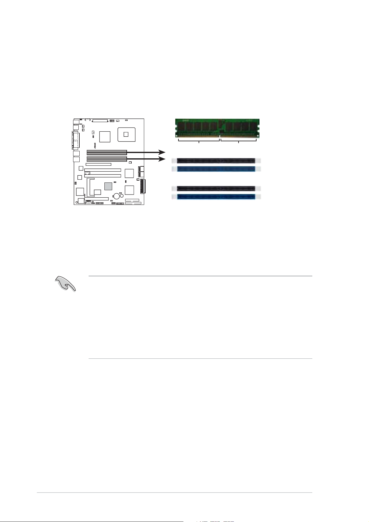
The motherboard comes with four Double Data Rate II (DDR2) Dual Inline
Memory Modules (DIMM) sockets to support 240-pin DDR modules.
The figure illustrates the location of the DDR DIMM sockets:
112 Pins128 Pins
LAN2
P5MT Series 240-pin DDR2 DIMM sockets
2.4.22.4.2
2.4.2
2.4.22.4.2
Memory configurationsMemory configurations
Memory configurations
Memory configurationsMemory configurations
DIMM_A1
DIMM_A2
DIMM_B1
DIMM_B2
You may install 256 MB, 512 MB, 1 GB, and 2 GB unbuffered ECC or
non-ECC DDR2-533/667 DIMMs into the DIMM sockets.
• Always install DIMMs with the same CAS latency. For optimum
compatibility, it is recommended that you obtain memory modules
from the same vendor. Refer to the DDR2 Qualified Vendors List at
the ASUS web site.
• When installing one or two DIMMs, install the DIMM(s) to the blue
slots (DIMM_A2/DIMM_B2).
• Three DDR DIMMs intalled into any three memory sockets will
function in single-channel mode.
2-102-10
2-10
2-102-10
Chapter 2: Hardware setupChapter 2: Hardware setup
Chapter 2: Hardware setup
Chapter 2: Hardware setupChapter 2: Hardware setup
 Loading...