

Page 1

¤
Star Ice Pro • Star Ice • Star Ice Lite!
Installation Guide
E1991E1991
E1991
E1991E1991
First EditionFirst Edition
First Edition
First EditionFirst Edition
April 2005April 2005
April 2005
April 2005April 2005
Page 2

English
EnglishEnglish
EnglishEnglish
Contents
1. Welcome! ................................................................................. 3
2. Package contents .................................................................... 3
3. Before you proceed ................................................................. 4
4. Installation procedures ............................................................ 4
4.1 Smart clip assembly ................................................... 4
4.2 Installing on Intel® Pentium™ 4 processor in
the LGA775 and 478-pin package ............................ 7
4.3 Installing on AMD K8 processor ................................. 9
4.4 Installing on AMD K7 processor ............................... 12
5. Smart 3-in-1 fan control feature ........................................... 14
5.1 Automatic control ................................................... 14
5.2 Manual controls ....................................................... 17
22
2
22
6. Optional installation ............................................................... 21
Page 3
1. Welcome!
Thank you for choosing the ASUS Star Ice! The Star Ice is an efficient CPU cooling system
that supports Intel® Pentium® 4 LGA775/478-pin and AMD K8/K7 CPUs. With the latest
cooling technology from ASUS, Star Ice lets you enjoy, share, and extend your game time.
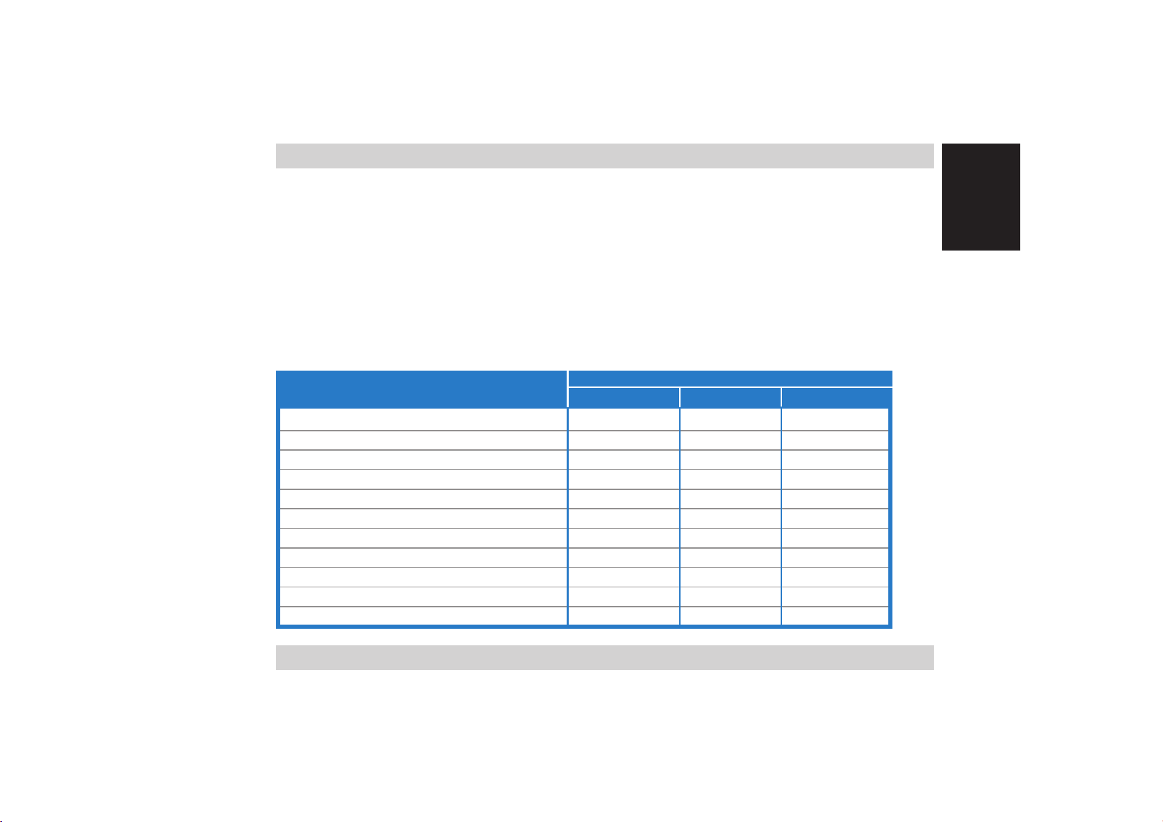
2. Package contents
Check the following items in your ASUS Star Ice package. Contact your retailer if any
item is damaged or missing.
ModelsModels
Models
Item DescriptionItem Description
Item Description
Item DescriptionItem Description
ASUS Star Ice CPU cooler • • •
3.5” fan controller • •
PCI bracket fan controller • •
4-in-1 smart clip set • • •
Screws and stand-offs • • •
Temperature sensor • •
Adhesive tape (for temperature sensor) • •
Thermal grease • • •
Metal underplate (H-bar) and rubber gasket • • •
Installation guide and parts list • • •
Additional fan and screws • Optional Optional
Star Ice ProStar Ice Pro
Star Ice Pro
Star Ice ProStar Ice Pro
ModelsModels
Star IceStar Ice
Star Ice
Star IceStar Ice
Star Ice Lite!Star Ice Lite!
Star Ice Lite!
Star Ice Lite!Star Ice Lite!
EnglishEnglish
EnglishEnglish
English
Installation guideInstallation guide
Installation guide
Installation guideInstallation guide
33
3
33
Page 4

English
EnglishEnglish
EnglishEnglish
3. Before you proceed
Take note of the following precautions before you install the Star Ice CPU cooler.
• Make sure to unplug the system power plug from the electrical socket before
you install or remove the CPU cooler.
• Install the CPU and the memory module(s) before you install the CPU cooler.
• Remove the chassis fan or the air duct on the chassis side panel to clear the air
path, if necessary.
• Install the Star Ice cooler on the motherboard before installing the
motherboard to the chassis.
• Have all components ready before installing the CPU cooler.
• Keep the parts list on hand when installing the CPU cooler.
4. Installation procedures
4.14.1
4.1
4.14.1
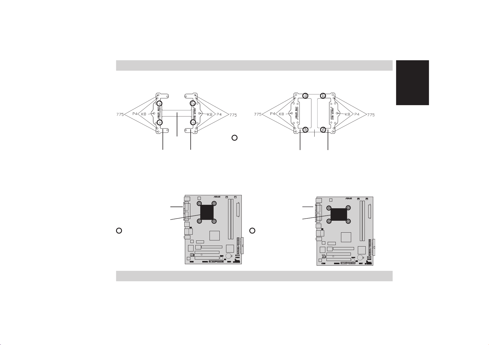
The multi-directional smart clip assembly holds the CPU cooler in place and lets you
direct the airflow to the chassis rear panel air vents. The smart clip is composed of
two U-bars with screw holes for Intel® Pentium® 4 LGA775/478-pin or K8 CPU, and an
H-bar that connects the two U-bars. Refer to the illustration on the next page.
44
4
44
Smart clip assemblySmart clip assembly
Smart clip assembly
Smart clip assemblySmart clip assembly
Page 5
Open typeOpen type
Open type
Open typeOpen type
H-barH-bar
H-bar
H-barH-bar
screws screws
screws
screws screws
Close typeClose type
Close type
Close typeClose type
H-barH-bar
H-bar
H-barH-bar
EnglishEnglish
EnglishEnglish
English
U-barU-bar
U-bar
U-barU-bar
If you will install the CPU cooler on
U-barU-bar
U-bar
U-barU-bar
IntelIntel
Intel
IntelIntel
®®
®
®®
Pentium Pentium
Pentium
Pentium Pentium
U-barU-bar
U-bar
U-barU-bar
®®
®
®®
4 (478-pin) 4 (478-pin)
4 (478-pin) or
4 (478-pin) 4 (478-pin)
U-barU-bar
U-bar
U-barU-bar
K8 K8
K 8 processor,
K8 K8
determine the position of the CPU socket and screw holes, then select the type of smart
clip assembly to use. Refer to the P4 (478-pin) motherboard illustrations below.
Rear panelRear panel
Rear panel
Rear panelRear panel
I/O portsI/O ports
I/O ports
I/O portsI/O ports
CPU socketCPU socket
CPU socket
CPU socketCPU socket
screw holes screw holes
screw holes
screw holes screw holes
Use the open type
smart clip assembly
for this motherboard.
Installation guideInstallation guide
Installation guide
Installation guideInstallation guide
®
Rear panelRear panel
Rear panel
Rear panelRear panel
I/O portsI/O ports
I/O ports
I/O portsI/O ports
CPU socketCPU socket
CPU socket
CPU socketCPU socket
screw holes screw holes
screw holes
screw holes screw holes
Use the close type
smart clip assembly
for this motherboard.
®
55
5
55
Page 6
English
EnglishEnglish
EnglishEnglish
®®
®
When installing on
PentiumPentium
Pentium
PentiumPentium
recommend that you use the
®®
4 (LGA775) 4 (LGA775)
4 (LGA775) processor, we
4 (LGA775) 4 (LGA775)
open type open type
open type smart clip assembly.
open type open type
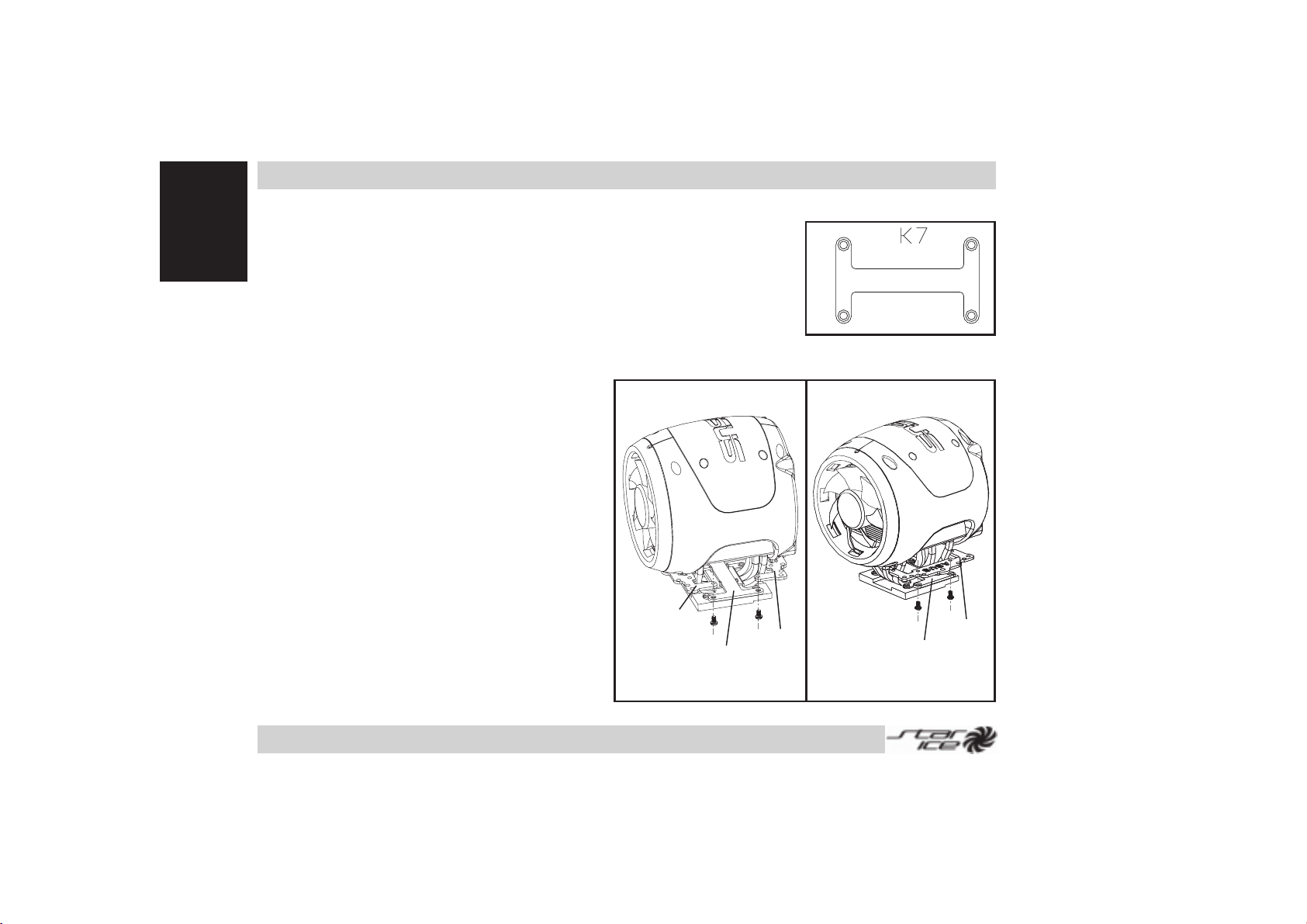
When installing on
K7 K7
K 7 processor, use only the H-bar to
K7 K7
hold the CPU cooler in place.
Installing the smart clip assemblyInstalling the smart clip assembly
Installing the smart clip assembly
Installing the smart clip assemblyInstalling the smart clip assembly
Close typeClose type
Close type
Close typeClose type
Close typeClose type
Close type
Close typeClose type
1. Insert the H-bar to the
heatsink rail.
2. Fasten the U-bars on both
sides of the H-bar using #1
screws (ASUS logo facing up).
Open typeOpen type
Open type
Open typeOpen type
1. Attach a U-bar to one end of
the H-bar with two screws (#1).
U-barU-bar
U-bar
2. Insert the other end of the
H-bar to the heatsink rails,
U-barU-bar
H-barH-bar
H-bar
H-barH-bar
then attach the other U-bar
with two screws (#1).
U-barU-bar
U-bar
U-barU-bar
Open typeOpen type
Open type
Open typeOpen type
U-barU-bar
U-bar
U-barU-bar
H-barH-bar
H-bar
H-barH-bar
66
6
66
Page 7
4.24.2
4.2
4.24.2
®®
®
Installing on IntelInstalling on Intel
Installing on Intel
Installing on IntelInstalling on Intel
the LGA775 and 478-pin packagethe LGA775 and 478-pin package
the LGA775 and 478-pin package
the LGA775 and 478-pin packagethe LGA775 and 478-pin package
®®
Pentium Pentium
Pentium™
Pentium Pentium
4 processor in 4 processor in
4 processor in
4 processor in 4 processor in
EnglishEnglish
EnglishEnglish
English
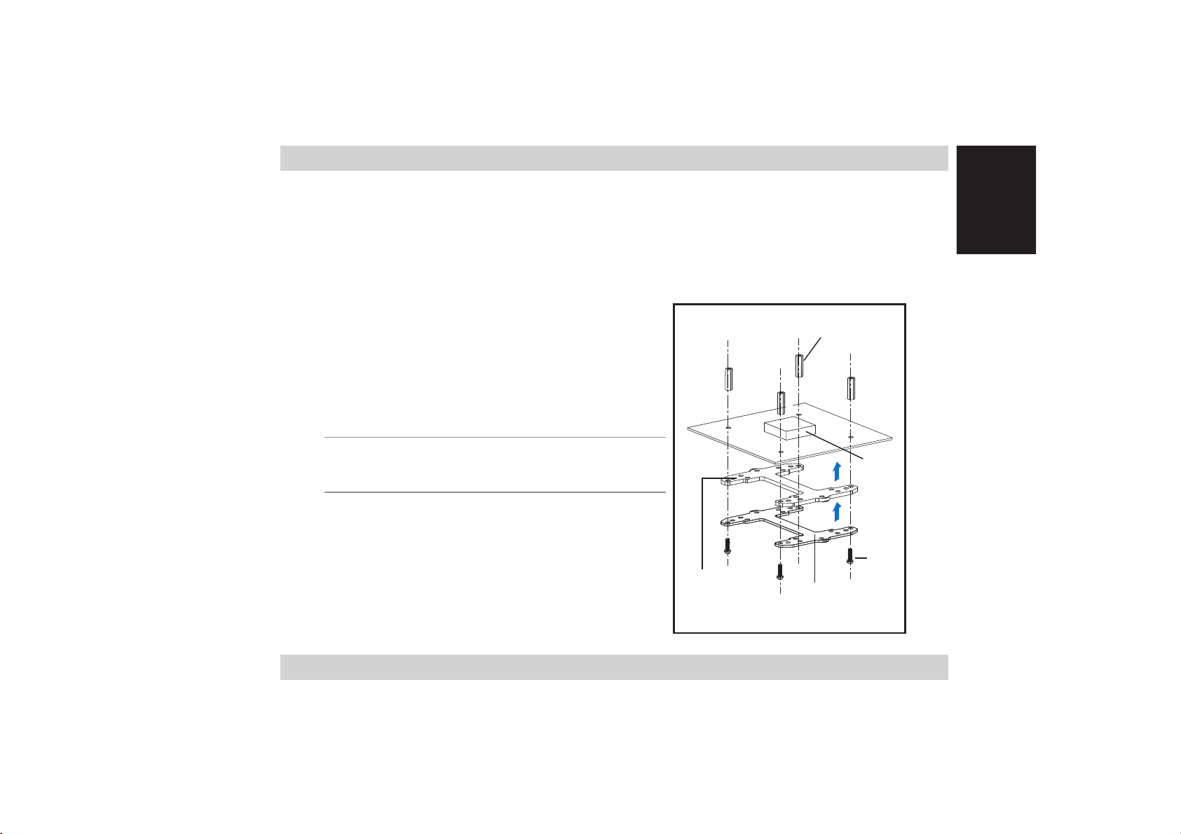
4.2.14.2.1
4.2.1
4.2.14.2.1
1. Locate the CPU socket screw holes.
2. Position the metal underplate and rubber
gasket underneath the motherboard, then
insert four screws (#2) to the underplate
screw holes matching that of the CPU socket
screw holes.
NOTE.NOTE.
NOTE. Make sure that the insulated side of
NOTE.NOTE.
the metal underplate faces the rubber gasket.
3. When the screws protrude on the top side of
the motherboard, drive in four copper stand-offs
(#5) to the screws, then tighten in a diagonal
sequence(two opposite corners at a time).
4. Apply the thermal grease evenly on top of the
installed CPU.
Installation guideInstallation guide
Installation guide
Installation guideInstallation guide
Placing the stand-offsPlacing the stand-offs
Placing the stand-offs
Placing the stand-offsPlacing the stand-offs
RubberRubber
Rubber
RubberRubber
gasketgasket
gasket
gasketgasket
Stand-offStand-off
Stand-off
Stand-offStand-off
MetalMetal
Metal
MetalMetal
underplateunderplate
underplate
underplateunderplate
CPUCPU
CPU
CPUCPU
#2#2
#2
#2#2
77
7
77
Page 8

English
EnglishEnglish
EnglishEnglish
4.2.24.2.2
4.2.2
4.2.24.2.2
Installing the coolerInstalling the cooler
Installing the cooler
Installing the coolerInstalling the cooler
1. Determine the CPU socket orientation and
the location of the chassis rear panel air
vents.
2. Assemble the smart clip following the
instructions in section 4.1.
NOTENOTE
N O TE. If you are installing on a P4
NOTENOTE
478-pin CPU, make sure that you select
the correct smart clip assembly. See
section 4.1 for details.
CoolCool
Cool
CoolCool
airair
air
airair
3. Place the cooler on top of the CPU. Make
sure that the airflow is directed towards
the chassis rear panel air vents.
4. Use a screw driver to drive in four screws
(#3) to the stand-offs, then tighten the
screws in a diagonal sequence (two
opposite corners at a time) until the CPU
cooler is firmly in place.
CPUCPU
CPU
CPUCPU
Hot airHot air
Hot air
Hot airHot air
#3#3
#3
#3#3
Smart clipSmart clip
Smart clip
Smart clipSmart clip
Stand-offStand-off
Stand-off
Stand-offStand-off
88
8
88
Page 9

4.34.3
4.3
4.34.3
Installing on AMD K8 processorInstalling on AMD K8 processor
Installing on AMD K8 processor
Installing on AMD K8 processorInstalling on AMD K8 processor
EnglishEnglish
EnglishEnglish
English
4.3.14.3.1
4.3.1
4.3.14.3.1
1. Remove the retention module.
2. Drive in two nickel stand-off screws (#4) to
the backplate stand-offs, then tighten.
3. Apply the thermal grease evenly on top of the
installed CPU.
Motherboard Motherboard
Motherboard
Motherboard Motherboard
with backplatewith backplate
with backplate
with backplatewith backplate
and and
and
and and
retention moduleretention module
retention module
retention moduleretention module
CPUCPU
CPU
CPUCPU
BackplateBackplate
Backplate
BackplateBackplate
(underneath)
Stand-offStand-off
Stand-off
Stand-offStand-off
#4#4
#4
#4#4
Installation guideInstallation guide
Installation guide
Installation guideInstallation guide
99
9
99
Page 10

English
EnglishEnglish
EnglishEnglish
4.3.24.3.2
4.3.2
4.3.24.3.2
1. Locate the CPU socket screw holes.
2. Position the metal underplate and rubber
gasket underneath the motherboard, then
insert two screws (#2) to the underplate
screw holes matching that of the CPU socket
screw holes.
NOTE.NOTE.
NOTE. Make sure that the insulated side of
NOTE.NOTE.
the metal underplate faces the rubber gasket.
3. When the screws protrude on the top side of
the motherboard, drive in two nickel
stand-offs (#7) to the screws, then tighten.
4. Apply the thermal grease evenly on top of the
installed CPU.
Motherboard Motherboard
Motherboard
Motherboard Motherboard
modulemodule
module
modulemodule
without backplatewithout backplate
without backplate
without backplatewithout backplate
RubberRubber
Rubber
RubberRubber
gasketgasket
gasket
gasketgasket
and and
and
and and
retentionretention
retention
retentionretention
Stand-offStand-off
Stand-off
Stand-offStand-off
MetalMetal
Metal
MetalMetal
underplateunderplate
underplate
underplateunderplate
CPUCPU
CPU
CPUCPU
#2#2
#2
#2#2
1010
10
1010
Page 11

4.3.34.3.3
4.3.3
4.3.34.3.3
Installing the coolerInstalling the cooler
Installing the cooler
Installing the coolerInstalling the cooler
1. Determine the CPU socket orientation and
the location of the chassis rear panel air
vents.
2. Assemble the smart clip following the
instructions in section 4.1.
3. Place the cooler on top of the CPU. Make
sure that the airflow is directed towards
the chassis rear panel air vents.
CoolCool
Cool
4. Use a screw driver to drive in two screws
(#3) to the stand-offs, then tighten until
CoolCool
airair
air
airair
the CPU cooler is firmly in place.
CPUCPU
CPU
CPUCPU
Hot airHot air
Hot air
Hot airHot air
#3#3
#3
#3#3
Smart clipSmart clip
Smart clip
Smart clipSmart clip
Stand-offStand-off
Stand-off
Stand-offStand-off
EnglishEnglish
EnglishEnglish
English
Installation guideInstallation guide
Installation guide
Installation guideInstallation guide
1111
11
1111
Page 12

English
EnglishEnglish
EnglishEnglish
4.44.4
4.4
4.44.4
4.4.14.4.1
4.4.1
4.4.14.4.1
1. Locate the CPU socket screw holes.
2. Position the metal underplate and rubber
gasket underneath the motherboard, then
insert four screws (#2) to the underplate
screw holes matching that of the CPU socket
screw holes.
NOTE.NOTE.
NOTE. Make sure that the insulated side of
NOTE.NOTE.
the metal underplate faces the rubber gasket.
3. When the screws protrude on the top side of
the motherboard, drive in four copper
stand-offs (#6) to the screws, then tighten in
a diagonal sequence (two opposite corners at
a time).
4. Apply the thermal grease evenly on top of the
installed CPU.
Installing on AMD K7 processorInstalling on AMD K7 processor
Installing on AMD K7 processor
Installing on AMD K7 processorInstalling on AMD K7 processor
Placing the stand-offsPlacing the stand-offs
Placing the stand-offs
Placing the stand-offsPlacing the stand-offs
RubberRubber
Rubber
RubberRubber
gasketgasket
gasket
gasketgasket
Stand-offStand-off
Stand-off
Stand-offStand-off
MetalMetal
Metal
MetalMetal
underplateunderplate
underplate
underplateunderplate
CPUCPU
CPU
CPUCPU
#2#2
#2
#2#2
1212
12
1212
Page 13

4.4.24.4.2
4.4.2
4.4.24.4.2
Installing the coolerInstalling the cooler
Installing the cooler
Installing the coolerInstalling the cooler
1. Determine the CPU socket orientation and
the location of the chassis rear panel air
vents.
2. Place the H-bar on the heatsink rail.
3. Place the cooler on top of the CPU. Make
sure that the airflow is directed towards
the chassis rear panel air vents.
NOTE.NOTE.
NOTE. Make sure that you position the
NOTE.NOTE.
CPU cooler with the heatsink surface
CoolCool
Cool
CoolCool
airair
air
airair
matching the elevated side of the CPU
socket. Refer to the illustration.
4. Use a screw driver to drive in four screws
(#3) to the stand-offs, then tighten in a
diagonal sequence (two opposite corners
at a time) until the CPU cooler is firmly in
place.
CPUCPU
CPU
CPUCPU
Hot airHot air
Hot air
Hot airHot air
#3#3
#3
#3#3
H-barH-bar
H-bar
H-barH-bar
Stand-offStand-off
Stand-off
Stand-offStand-off
EnglishEnglish
EnglishEnglish
English
Installation guideInstallation guide
Installation guide
Installation guideInstallation guide
1313
13
1313
Page 14

English
EnglishEnglish
EnglishEnglish
5. Smart 3-in-1 fan control feature
The Star Ice Pro/Star Ice package includes an automatic CPU temperature sensor and
two manual fan control solutions: 3.5” control bracket and PCI control bracket. You
can install only one fan control solution at a time. For Star Ice Lite!, use the ASUS
Q-Fan feature to automatically control the CPU cooler. Refer to the ASUS
motherboard user guide for details on the ASUS Q-Fan feature.
IMPORTANT.IMPORTANT.
IMPORTANT. Remove the jumper on the 2-pin CPU cooler cable
IMPORTANT.IMPORTANT.
connector before installing any of the fan controls.
5.15.1
5.1
5.15.1
NOTE. NOTE.
NOTE. Install the temperature sensor before installing the CPU cooler on
NOTE. NOTE.
the CPU.
The temperature sensor allows automatic control of the CPU cooler.
When you install the temperature sensor, the CPU cooler fan rotation automatically
adjusts depending on the CPU temperature. The higher the CPU temperature, the faster
the fan rotation, and vice-versa. Refer to the fan speed curve on page 18 for details.
1414
14
1414
Automatic controlAutomatic control
Automatic control
Automatic controlAutomatic control
Page 15

5.1.15.1.1
5.1.1
5.1.15.1.1
NOTESNOTES
NOTES
NOTESNOTES
To install the temperature sensor:
1. Lay the CPU cooler on its front to expose the
heatsink surface.
2. Cut the adhesive tape just enough to cover the
temperature sensor.
3. Peel one side (no label) of the tape, attach the
sensor to the lower side of the heatsink surface,
then secure it with the tape.
Make sure that the tape covers the entire sensor.
Temperature sensor installationTemperature sensor installation
Temperature sensor installation
Temperature sensor installationTemperature sensor installation
••
• Do not install the sensor between the CPU and the heatsink.
••
• Do not fold or cut the sensor.
EnglishEnglish
EnglishEnglish
English
Installation guideInstallation guide
Installation guide
Installation guideInstallation guide
1515
15
1515
Page 16

English
EnglishEnglish
EnglishEnglish
3. Remove the labeled side of the
adhesive tape, then install the CPU
cooler on top of the CPU.
5.1.25.1.2
5.1.2
5.1.25.1.2
Fan speed curveFan speed curve
Fan speed curve
Fan speed curveFan speed curve
Refer to the fan speed curve on the right
when using the temperature sensor
control.
4. Connect the temperature sensor
cable to the 2-pin cable connector
from the CPU cooler.
HIGHHIGH
HIGH
HIGHHIGH
NormalNormal
Normal
NormalNormal
Fan SpeedFan Speed
Fan SpeedFan Speed
Fan Speed
LOWLOW
LOW
LOWLOW
PerformancePerformance
Performance
PerformancePerformance
System loadingSystem loading
System loading
System loadingSystem loading
OverclockingOverclocking
Overclocking
OverclockingOverclocking
1616
16
1616
Page 17

5.25.2
5.2
5.25.2
If you want to manually control the fan rotation, you can install either the 3.5”
control bracket or the PCI control bracket solution. Both controls allow you to adjust
the fan speed in just a turn of a dial. Refer to the table below for the fan speed
information.
Manual controlsManual controls
Manual controls
Manual controlsManual controls
Fan speed (rpm)Fan speed (rpm)
Fan speed (rpm)
ModelModel
Model
ModelModel
Star Ice Pro 3000 1000
Star Ice 4500 1500
Star Ice Lite! n/a n/a
Max. (±10%)Max. (±10%)
Max. (±10%)
Max. (±10%)Max. (±10%)
Fan speed (rpm)Fan speed (rpm)
Min. (±10%)Min. (±10%)
Min. (±10%)
Min. (±10%)Min. (±10%)
EnglishEnglish
EnglishEnglish
English
5.2.15.2.1
5.2.1
5.2.15.2.1
If your system has an empty 3.5” floppy disk drive bay,
you can install the 3.5” control bracket and control the
fan rotation from the system front panel.
To install the 3.5” control bracket:To install the 3.5” control bracket:
To install the 3.5” control bracket:
To install the 3.5” control bracket:To install the 3.5” control bracket:
1. Remove the system front panel cover and the FDD
bay cover following the instructions in the system
documentation.
Installation guideInstallation guide
Installation guide
Installation guideInstallation guide
3.5” control bracket installation3.5” control bracket installation
3.5” control bracket installation
3.5” control bracket installation3.5” control bracket installation
1717
17
1717
Page 18

English
EnglishEnglish
EnglishEnglish
2. Insert first the bracket cable, then
the control bracket to the empty
bay until it fits in place.
4. Connect the bracket cable to the 2-pin
cable connector from the CPU cooler.
3. Secure the bracket with two
screws (two on each side of the
bay).
5. Remove the system front panel FDD
bay cover, then re-install.
1818
18
1818
Page 19

5.2.25.2.2
5.2.2
5.2.25.2.2
If your system rear panel has a PCI bracket space, you can install the PCI control bracket.
To install the PCI control bracket:To install the PCI control bracket:
To install the PCI control bracket:
To install the PCI control bracket:To install the PCI control bracket:
1. Remove the system cover following the instructions
in the system documentation, then lay the system
on its side on a flat surface.
2. Remove the PCI control bracket protective cover.
3. Remove a dummy PCI metal bracket. Keep the
screw for later use.
PCI control bracket installationPCI control bracket installation
PCI control bracket installation
PCI control bracket installationPCI control bracket installation
EnglishEnglish
EnglishEnglish
English
Installation guideInstallation guide
Installation guide
Installation guideInstallation guide
1919
19
1919
Page 20

English
EnglishEnglish
EnglishEnglish
4. Align the PCI control bracket to the
PCI space
6. Connect the bracket cable to the
2-pin CPU cooler cable connector.
5. Secure the PCI control bracket with
7. Replace the system cover. Below
the screw you removed earlier.
photo shows the installed PCI
control bracket.
2020
20
2020
Page 21

6. Optional installation
Dual fan upgrade kitDual fan upgrade kit
Dual fan upgrade kit
Dual fan upgrade kitDual fan upgrade kit
The Star Ice Pro package comes with a dual fan upgrade kit (8 cm fan and screws)
to keep the CPU cooler and more efficient. For Star Ice and Star Ice Lite models, you
may purchase the dual fan upgrade kit separately.
To upgrade the CPU cooler to dual fan:To upgrade the CPU cooler to dual fan:
To upgrade the CPU cooler to dual fan:
To upgrade the CPU cooler to dual fan:To upgrade the CPU cooler to dual fan:
1. Prepare the dual fan upgrade kit components. You
will need a Philips (cross) screw driver to install.
2. Place the fan on the CPU cooler rear panel, then
secure the fan with four screws.
3. Open the system cover, then install the CPU cooler
on top of the CPU.
IMPORTANT.IMPORTANT.
IMPORTANT. Make sure that the air flows in a
IMPORTANT.IMPORTANT.
single direction from the CPU cooler fan to the
second fan. Refer to the illustration on the next
page.
EnglishEnglish
EnglishEnglish
English
Installation guideInstallation guide
Installation guide
Installation guideInstallation guide
2121
21
2121
Page 22

English
EnglishEnglish
EnglishEnglish
4. Connect the second fan cable to an available fan
connector on the motherboard, then replace the
system cover.
How dual fan upgrade worksHow dual fan upgrade works
How dual fan upgrade works
How dual fan upgrade worksHow dual fan upgrade works
Air enters the CPUAir enters the CPU
Air enters the CPU
Air enters the CPUAir enters the CPU
cooler via thecooler via the
cooler via the
cooler via thecooler via the
main fan, thenmain fan, then
main fan, then
main fan, thenmain fan, then
passes throughpasses through
passes through
passes throughpasses through
the coolerthe cooler
the cooler
the coolerthe cooler
heatsink finsheatsink fins
heatsink fins
heatsink finsheatsink fins
2222
22
2222
The second fanThe second fan
The second fan
The second fanThe second fan
blows the warm airblows the warm air
blows the warm air
blows the warm airblows the warm air
out from theout from the
out from the
out from theout from the
cooler to thecooler to the
cooler to the
cooler to thecooler to the
chassis rear panelchassis rear panel
chassis rear panel
chassis rear panelchassis rear panel
air ventsair vents
air vents
air ventsair vents
 Loading...