

Page 1

SD434-YB
User Manual (English)
Page 2
SD434-YB
Safety Instructions
Warnings and Precautions
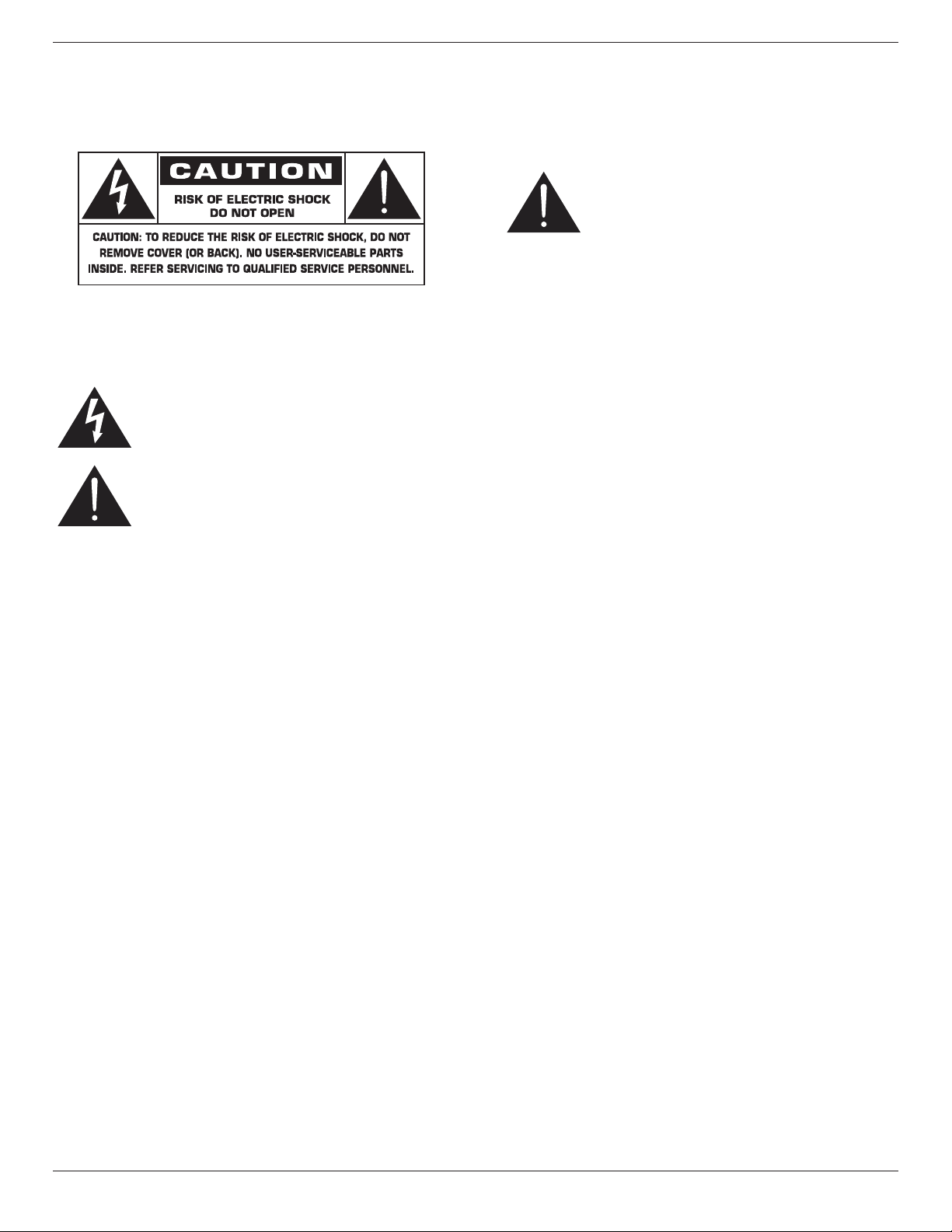
KNOW THESE SAFETY SYMBOLS
CAUTION: TO REDUCE THE RISK OF ELECTRIC SHOCK, DO
NOT REMOVE COVER (OR BACK). NO USER
SERVICEABLE PARTS INSIDE. REFER SERVICING TO
QUALIFIED SERVICE PERSONNEL.
This symbol indicates high voltage is present inside.
It is dangerous to make any kind of contact with any
inside part of this product.
This symbol alerts you that important literature
concerning operation and maintenance has been
included with this product.
CAUTION: FCC/CSA regulations state that any unauthorized
changes or modications to this equipment may void
the user’s authority to operate it.
CAUTION: To prevent electric shock, match the wide blade of plug
to the wide slot, and fully insert the plug.
TO PREVENT DAMAGE WHICH MAY RESULT IN FIRE OR ELECTRIC
SHOCK HAZARD, DO NOT EXPOSE THIS APPLIANCE TO RAIN
OR MOISTURE.
The Socket-outlet should be installed near the apparatus and be easily
accessible.
Read and follow these instructions
when connecting and using your Public
Information Display:
• Unplug the display if you are not going to use it for an extensive
period of time.
• Unplug the display if you need to clean it with a slightly damp cloth.
The screen many be wiped with a dry cloth when the power is off.
However, never use alcohol, solvents or ammonia-based liquids.
• Consult a service technician if the display does not operate normally
when you have followed the instructions in this manual.
• The casing cover should be opened only by qualied service
personnel.
• Keep the display out of direct sunlight and away from stoves or any
other heat sources.
• Remove any object that could fall into the vents or prevent proper
cooling of the display’s electronics.
• Do not block the ventilation holes on the cabinet.
• Keep the display dry. To avoid electric shock, do not expose it to
rain or excessive moisture.
• If turning off the display by detaching the power cable, wait for 6
seconds before re-attaching the power cable for normal operation.
• To avoid the risk of shock or permanent damage to the set do not
expose the display to rain or excessive moisture.
• When positioning the display, make sure the power plug and outlet
are easily accessible.
• IMPORTANT: Always activate a screen saver program during your
application. If a still image in high contrast remains on the screen for
an extended period of time, it may leave an ‘after-image’ or ‘ghost
image’ on the front of the screen. This is a well-known phenomenon
that is caused by the shortcomings inherent in LCD technology. In
most cases the afterimage will disappear gradually over a period
of time after the power has been switched off. Be aware that the
after-image symptom cannot be repaired and is not covered under
warranty.
ii
Page 3
SD434-YB
Important Safety Instructions
1. Read these instructions.
2. Keep these instructions.
3. Heed all warnings.
4. Follow all instructions.
5. Do not use this apparatus near water.
6. Clean only with dry cloth.
7. Do not block any ventilation openings. Install in accordance with the
manufacturer’s instructions.
8. Do not install near any heat sources such as radiators, heat registers,
stoves, or other apparatus (including ampliers) that produce heat.
9. Do not defeat the safety purpose of the polarized or groundingtype plug. A polarized plug has two blades with one wider than the
other. A grounding type plug has two blades and a third grounding
prong. The wide blade or the third prong are provided for your
safety. If the provided plug does not t into your outlet, consult an
electrician for replacement of the obsolete outlet.
10. Protect the power cord from being walked on or pinched
particularly at plugs, convenience receptacles, and the point where
they exit from the apparatus.
11. Only use attachments/accessories specied by the manufacturer.
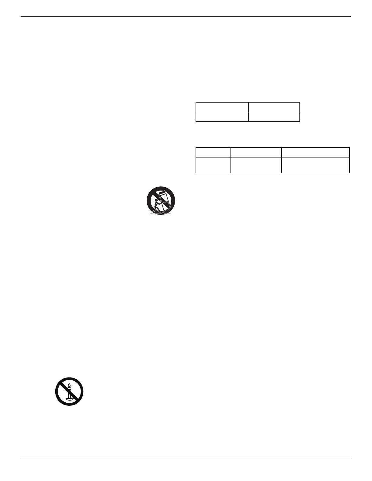
12. Use only with the cart, stand, tripod, bracket, or
table specied by the manufacturer, or sold with the
apparatus. When a cart is used, use caution when
moving the cart/apparatus combination to avoid
injury from tip-over.
13. Unplug this apparatus during lightning storms or when unused for
long periods of time.
14. Refer all servicing to qualied service personnel. Servicing is
required when the apparatus has been damaged in any way, such
as power-supply cord or plug is damaged, liquid has been spilled
or objects have fallen into the apparatus, the apparatus has been
exposed to rain or moisture, does not operate normally, or has
been dropped.
contained in the operating instructions unless you are
qualitied to do so.
CAUTION: Excessive sound pressure from earphones and
headphones can cause hearing loss. Adjustment of the
equalizer to maximum increases the earphone and
headphone output voltage and the sound pressure level.
Therefore, to protect your hearing, adjust the equalizer
to an appropriate level.
For UL/CUL application: For use only with UL Listed Wall Mount
Bracket with minimum weight/load: W Kg
Model Name W (kg)
SD434-YB
For CB application: Unit without base weight: W Kg. The equipment
and its associated mounting means still remain secure during the test.
(Used wall mounting kit as following table shown).
Model Name Wall Mount Grid Screw
SD434-YB
.
8.7
400x400, 200x200
M6x(10+X), X=thickness of
wall mount plate
WARNING: TO REDUCE THE RISK OF FIRE OR ELECTRIC
SHOCK, DO NOT EXPOSE THIS APPARATUS TO
RAIN OR MOISTURE.
WARNING: Apparatus shall not be exposed to dripping or splashing
and no objects lled with liquids, such as vases, shall be
placed on the apparatus.
WARNING: The batteries (batteries installed) shall not be exposed
to excessive heat such as sunshine, re or the like.
WARNING: The mains plug or appliance coupler is used as the
disconnect device,the disconnect device shall remain
readily operable.
WARNING: To prevent the spread of re, keep candles or other
open ames away from this product at all times.
WARNING: To prevent injury, this apparatus must be securely
attached to the oor/wall in accordance with the
installation instructions.
CAUTION: These servicing instructions are for use by qualied
service personnel only. To reduce the risk of electric
shock,do not perform any servicing other than that
iii
Page 4
SD434-YB
Regulatory Information
CE Declaration of Conformity
This device complies with the requirements set out in the Council
Directive on the Approximation of the Laws of the Member States
relating to Electromagnetic Compatibility (2014/30/EU), Low-voltage
Directive (2014/35/EU), RoHS directive (2011/65/EU).
This product has been tested and found to comply with the harmonized
standards for Information Technology Equipment, these harmonized
standards published under Directives of Ofcial Journal of the European
Union.
Warning:
This equipment is compliant with Class A of EN55032. In a residential
environment this equipment may cause radio interference.
Federal Communications Commission (FCC)
Notice (U.S. Only)
Note: This equipment has been tested and found to
comply with the limits for a Class A digital
device, pursuant to part 15 of the FCC Rules. These
limits are designed to provide reasonable
protection against harmful interference when the
equipment is operated in a commercial
environment. This equipment generates, uses, and can
radiate radio frequency energy and, if
not installed and used in accordance with the
instruction manual, may cause harmful
interference to radio communications. Operation of
this equipment in a residential area is
likely to cause harmful interference in which case the
user will be required to correct the
interference at his own expense.
Changes or modications not expressly approved by
the party responsible for compliance could void the
user’s authority to operate the equipment.
Use only an RF shielded cable that was supplied with the display when
connecting this display to a computer device.
To prevent damage which may result in re or shock hazard, do not
expose this appliance to rain or excessive moisture.
This device complies with Part 15 of the FCC Rules.
Operation is subject to the following two conditions:
(1) this device may not cause harmful interference,
and (2) this device must accept any interference
received, including interference that may cause
.
undesired operation.
iv
Page 5
SD434-YB
Polish Center for Testing and Certication
Notice
The equipment should draw power from a socket with an attached
protection circuit (a three-prong socket). All equipment that works
together (computer, display, printer, and so on) should have the same
power supply source.
The phasing conductor of the room’s electrical installation should have
a reserve short-circuit protection device in the form of a fuse with a
nominal value no larger than 16 amperes (A).
To completely switch off the equipment, the power supply cable must
be removed from the power supply socket, which should be located
near the equipment and easily accessible.
A protection mark “B” conrms that the equipment is in compliance
with the protection usage requirements of standards PN-93/T-42107
and PN-89/E-06251.
Information for U.K. only
WARNING – THIS APPLIANCE MUST BE EARTHED.
Important:
(B)
(A)
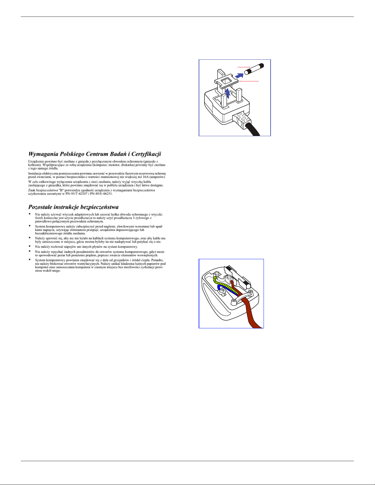
This apparatus is supplied with an approved moulded 13A plug. To
change a fuse in this type of plug proceed as follows:
1. Remove fuse cover and fuse.
2. Fit new fuse which should be a BS 1362 5A,A.S.T.A. or BSI approved
type.
3. Ret the fuse cover.
If the tted plug is not suitable for your socket outlets, it should be cut
off and an appropriate 3-pin plug tted in its place.
If the mains plug contains a fuse, this should have a value of 5A. If a plug
without a fuse is used, the fuse at the distribution board should not be
greater than 5A.
NOTE: The severed plug must be destroyed to avoid a possible shock
hazard should it be inserted into a 13A socket elsewhere.
How to connect a plug
The wires in the mains lead are coloured in accordance with the
following code:
BLUE – “NEUTRAL” (“N”)
BROWN – “LIVE” (“L”)
GREEN & YELLOW – “EARTH” (“E”)
1. The GREEN & YELLOW wire must be connected to the terminal in
the plug which is marked with the letter “E” or by the Earth symbol
or coloured GREEN or GREEN & YELLOW.
2. The BLUE wire must be connected to the terminal which is marked
with the letter “N” or coloured BLACK.
3. The BROWN wire must be connected to the terminal which
marked with the letter “L” or coloured RED.
Before replacing the plug cover, make certain that the cord grip is
clamped over the sheath of the lead – not simply over the three wires.
v
Page 6
SD434-YB
North Europe (Nordic Countries)
Information
Placering/Ventilation
VARNING:
FÖRSÄKRA DIG OM ATT HUVUDBRYTARE OCH UTTAG
ÄR LÄTÅTKOMLIGA, NÄR DU STÄLLER DIN UTRUSTNING
PÅPLATS.
Placering/Ventilation
ADVARSEL:
SØRG VED PLACERINGEN FOR, AT NETLEDNINGENS STIK OG
STIKKONTAKT ER NEMT TILGÆNGELIGE.
Paikka/Ilmankierto
VAROITUS:
SIJOITA LAITE SITEN, ETTÄ VERKKOJOHTO VOIDAAN
TARVITTAESSA HELPOSTI IRROTTAA PISTORASIASTA.
Plassering/Ventilasjon
ADVARSEL:
NÅR DETTE UTSTYRET PLASSERES, MÅ DU PASSE PÅ AT
KONTAKTENE FOR STØMTILFØRSEL ER LETTE Å NÅ.
End-of-Life Disposal
Your new Public Information Display contains materials that can be
recycled and reused. Specialized companies can recycle your product to
increase the amount of reusable materials and to minimize the amount
to be disposed of.
Please nd out about the local regulations on how to dispose of your
old display from your local dealer.
End of Life Directives-Recycling
Your new Public Information Display contains several
materials that can be recycled for new users.
Please dispose of according to all Local, State, and
Federal laws.
As an ENERGY STAR Partner, we have determined
that this product meets the ENERGY STAR guidelines
for energy efciency. .
Restriction on Hazardous Substances statement
(India)
This product complies with the “India E-waste Rule 2011” and prohibits
use of lead, mercury, hexavalent chromium, polybrominated biphenyls or
polybrominated diphenyl ethers in concentrations exceeding 0.1 weight
% and 0.01 weight % for cadmium, except for the exemptions set in
Schedule 2 of the Rule.
E-Waste Declaration for India
This symbol on the product or on its packaging
indicates that this product must not be disposed of
with your other household waste. Instead it is your
responsibility to dispose of your waste equipment by
handing it over to a designated collection point for the
recycling of waste electrical and electronic equipment
. The separate collection and recycling of your waste
equipment at the time of disposal will help to conserve
natural resources and ensure that it is recycled in a
manner that protects human health and the environment. For more information about where you can drop
off your waste equipment for recycling in India please
visit the below web link.
(For customers in Canada and U.S.A.)
This product may contain lead and/or mercury. Dispose of in accordance
to local-state and federal regulations. For additional information on
recycling contact www.eia.org (Consumer Education Initiative)
Waste Electrical and Electronie EquipmentWEEE
Attention users in European Union private households
This marking on the product or on its packaging
illustrates that, under European Directive 2012/19/
EU governing used electrical and electronic appliances,
this product may not be disposed of with normal
household waste. You are responsible for disposal of
this equipment through a designated waste electrical
and electronic equipment collection. To determine
the locations for dropping off such waste electrical
and electronic, contact your local government ofce,
the waste disposal organization that serves your
household or the store at which you purchased the
product.
vi
Page 7

SD434-YB
Table Of Contents
1. Unpacking and Installation .......................................................1
1.1. Unpacking .........................................................................................1
1.2. Package Contents ........................................................................1
1.3. Installation Notes .........................................................................1
1.4. Mounting on a Wall ....................................................................2
1.4.1. VESA Grid .................................................................... 2
1.5. Using of Remote sensor and power indicator ............3
2. Parts and Functions ...................................................................4
2.1. Control Panel .................................................................................4
2.2. Input/Output Terminals .............................................................5
2.3. Remote Control ...........................................................................6
2.3.1. General functions ..................................................... 6
2.3.2. Inserting the batteries in the remote
control.............................................................................7
2.3.3. Handling the remote control .............................7
2.3.4. Operating range of the remote control ......7
3. Connecting External Equipment.............................................8
3.1. Connecting External Equipment (DVD/VCR/VCD) 8
3.1.1. Using COMPONENT video input .................8
3.1.2. Using Video Source input .....................................8
3.1.3. Using HDMI video input ......................................9
3.2. Connecting a PC ..........................................................................9
3.2.1. Using VGA input ........................................................9
3.2.2. Using DVI input .........................................................9
3.2.3. Using HDMI input ................................................. 10
3.3. Connecting Audio Equipment ........................................... 10
3.3.1. Connecting an external audio device ........ 10
3.4. Connecting Multiple Displays in a Daisy-chain
Conguration .............................................................................. 11
3.4.1. Display control connection .............................. 11
3.5. IR Pass-through Connection ............................................... 11
3.6. Wire-connecting to Network ........................................... 12
5. Change your settings ............................................................. 16
5.1. Settings ............................................................................................ 16
5.1.1. Picture menu ............................................................ 16
5.1.2. Sound menu ............................................................. 17
5.1.3. General settings menu ........................................17
5.2. Network Settings ......................................................................18
6. USB device compatibility ....................................................... 19
7. Input Mode ............................................................................... 21
8. Cleaning and Troubleshooting .............................................. 22
8.1. Cleaning .......................................................................................... 22
8.2. Troubleshooting .........................................................................23
9. TechnicalSpecications ......................................................... 24
9.1. SD434-YB ..................................................................................... 24
4. Operation ................................................................................. 13
4.1. Change Picture Format ......................................................... 13
4.2. Play Multimedia Files ............................................................... 13
4.2.1. Play les from computer ................................... 13
4.2.2. Play multimedia les from USB device ......13
4.3. Play options .................................................................................. 14
4.3.1. Playing music les ..................................................14
4.3.2. Playing movie les .................................................14
4.3.3. Playing photo les .................................................15
vii
Page 8
1. Unpacking and Installation
1.1. Unpacking
• This product is packed in a carton, together with the standard accessories.
• Any other optional accessories will be packed separately.
• Due to the size and weight of this display it is recommended for two people to move it.
• After opening the carton, ensure that the contents are complete and in good condition.
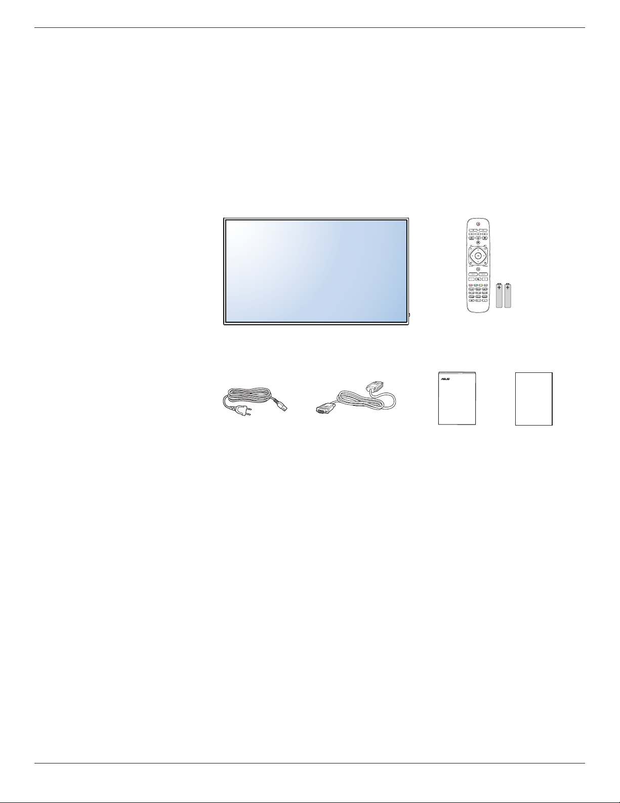
1.2. Package Contents
Please verify that you received the following items with your package content:
• LCD display
• Remote control with AAA batteries
• Power cord (1.5 m)
• VGA cable (1.5 m)
• Quick Start Guide
• Warranty Card
SD434-YB
Remote Control
and AAA Batteries
* The supplied power cord varies depending on destination.
Power Cord
NOTES:
• For all other regions, apply a power cord that conforms to the AC voltage of the power socket and has been approved by and complies with the
safety regulations of the particular country.
• You might like to save the package box and packing material for shipping the display.
Video Signal Cable
(D-SUB to D-SUB Cable)
Quick Start Guide
Warranty Card
1.3. Installation Notes
• Due to the high power consumption, always use the plug exclusively designed for this product. If an extended line is required, please consult your
service agent.
• The product should be installed on a at surface to avoid tipping. The distance between the back of the product and the wall should be maintained
for proper ventilation. Avoid installing the product in the kitchen, bathroom or any other places with high humidity so as not to shorten the service life
of the electronic components.
• The product can normally operate only under 3000m in altitude. In installations at altitudes above 3000m, some abnormalities may be experienced.
1
Page 9
SD434-YB
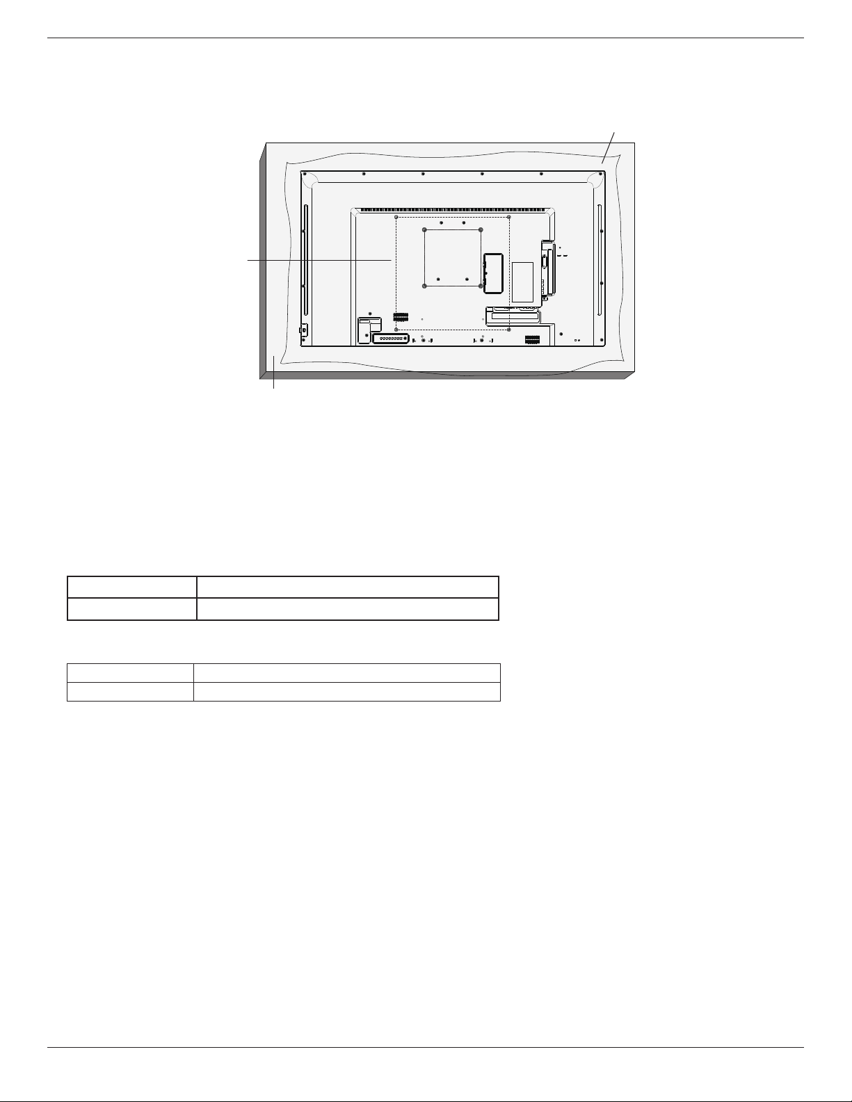
1.4. Mounting on a Wall
To mount this display to a wall, you will have to obtain a standard wall-mounting kit (commercially available). We recommend using a mounting interface
that complies with TUV-GS and/or UL1678 standard in North America.
Protective Sheet
VESA Grid
Table
1. Lay a protective sheet on a table, which was wrapped around the display when it was packaged, beneath the screen surface so as not to scratch the
screen face.
2. Ensure you have all accessories for mounting this display (wall mount, ceiling mount, table stand, etc).
3. Follow the instructions that come with the base mounting kit. Failure to follow correct mounting procedures could result in damage to the equipment
or injury to the user or installer. Product warranty does not cover damage caused by improper installation.
4. For the wall-mounting kit, use M6 mounting screws (having a length 10 mm longer than the thickness of the mounting bracket) and tighten them
securely.
5. Unit without base weight= W Kg. The equipment and its associated mounting means still remain secure during the test. For use only with UL Listed
Wall Mount Bracket with minimum weight/load: W Kg.
Model Name W (kg)
SD434-YB
8.7
1.4.1. VESA Grid
Model Name Vesa Grid
SD434-YB 200(H) x 200(V)mm / 400(H) x 400(V)mm
Caution:
To prevent the display from falling:
• For wall or ceiling installation, we recommend installing the display with metal brackets which are commercially available. For detailed installation
instructions, refer to the guide received with the respective bracket.
• To lessen the probability of injury and damage resulting from fall of the display in case of earthquake or other natural disaster, be sure to consult the
bracket manufacturer for installation location.
2
Page 10
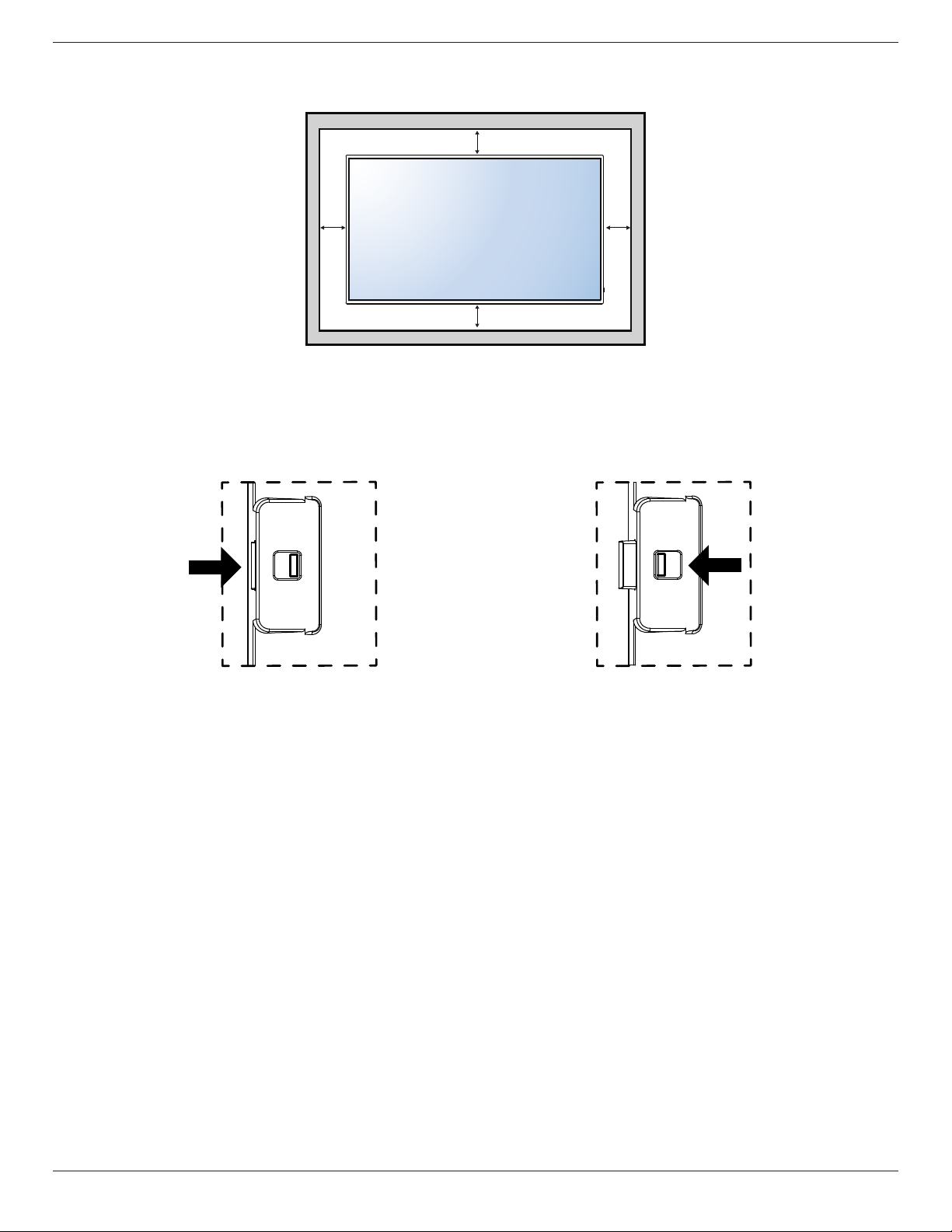
Ventilation Requirements for enclosure locating
To allow heat to disperse, leave space between surrounding objects as shown in the diagram below.
100 mm
100 mm 100 mm
100 mm
1.5. Using of Remote sensor and power indicator
1. Pull down the lens to have better remote control performance and easy to observe the light information of power status
2. Push up the lens before mounting the display for video wall application
3. Pull/Push the lens until hearing the click sound
SD434-YB
Push right to collapse the lens Push left to extend the lens
3
Page 11

SD434-YB
2. Parts and Functions
2.1. Control Panel
MUTE INPUT
MENU
1 2 3 4 5 6 7 8
1
[ ] button
Use this button to turn the display on or put the display to standby.
2
[MUTE] button
Switch the audio mute ON/OFF.
3
[INPUT] button
Choose the input source.
• Used as [ ] button in the On-Screen-Display menu.
4
[ ] button
Move the highlight bar up / Increase the adjustment while OSD
menu is on, or increase the audio output level while OSD menu is
off.
5
[ ] button
Move the highlight bar down / Decrease the adjustment while OSD
menu is on, or decrease the audio output level while OSD menu is
off.
7
[ ] button
Move the highlight bar down to adjust the selected item while OSD
menu is on.
8
[MENU] button
Return to previous menu while OSD menu is on, or to activate the
OSD menu when OSD menu is off.
6
[ ] button
Move the highlight bar up to adjust the selected item while OSD
menu is on.
4
Page 12

2.2. Input/Output Terminals
SD434-YB
USB
INOUTRJ45IN
15
14
13
12
2
11
1
OUT
10
16
9
LRL R
8
Y Pb Pr
3 4
5
6
7
1
MAIN POWER SWITCH
Switch the main power on/off.
2
AC IN
AC power input from the wall outlet.
3
PC LINE IN
Audio input from VGA source (3.5mm stereo phone).
4
HDMI IN
HDMI video / audio input.
5
DVI-D IN
DVI-D video input.
6
VGA IN (D-Sub)
VGA video input.
7
Y/CVBS
Video source input.
8
AUDIO IN
Audio input from external AV device (RCA).
9
AUDIO OUT
Audio output to external AV device.
10
IR OUT / 11 IR IN
IR signal output /input for the loop-through function.
NOTES:
• This display’s remote control sensor will stop working if the jack
[IR IN] is connected.
• To remotely control your A/V device via this display, refer to
page 11 for IR Pass Through connection.
12
RJ-45
LAN control function for the use of remote control signal from control
center.
13
RS232 OUT / 14 RS232 IN
RS232C network output / input for the loop-through function.
15
USB PORT
Connect your USB storage device.
16
Security LOCK
Used for security and theft prevention.
5
Page 13

SD434-YB
2.3. Remote Control
2.3.1. General functions
1
2
3
4
5
6
7
8
9
10
11
12
13
14
15
16
10
1
[ ] POWER button
Turn the display on or put the display to standby.
2
[PLAY] buttons
Control playback of media les.
3
[ ] SOURCE button
Choose input source. Press [ ] or [ ] button to choose from
USB, Network, HDMI, DVI, YPbPr, AV
[ ] button to conrm and exit.
4
[ ] HOME button
Access the OSD menu.
5
[ ] LIST button
No function.
6
[ ] [ ] [ ] [ ] NAVIGATION buttons
Navigate through menus and choose items.
7
[ ] button
Conrm an entry or selection.
8
[ ] ADJUST button
Access currently available options, picture and sound menus.
9
[ ] BACK button
Return to the previous menu page or exit from the previous
function.
10
[ ] [ ] VOLUME button
Adjust volume.
11
[ ] MUTE button
Press to turn the mute function on/off.
12
[ ] [ ] [ ] [ ] COLOR buttons
Choose tasks or options.
13
[NUMERIC] buttons
Enter text for network setting.
14
[ ] FORMAT button
Change picture format.
15
[ ] INFO button
Display information about current activity.
16
[ ] OPTIONS button
Access currently available options, picture and sound menus.
, or
VGA
. Press
6
Page 14

SD434-YB
2.3.2. Inserting the batteries in the remote control
The remote control is powered by two 1.5V AAA batteries.
To install or replace batteries:
1. Press and then slide the cover to open it.
2. Align the batteries according to the (+) and (–) indications inside the
battery compar tment.
3. Replace the cover.
Caution:
The incorrect use of batteries can result in leaks or bursting. Be sure to follow these instructions:
• Place “AAA” batteries matching the (+) and (–) signs on each battery to the (+) and (–) signs of the battery compartment.
• Do not mix battery types.
• Do not combine new batteries with used ones. It causes shorter life or leakage of batteries.
• Remove the dead batteries immediately to prevent them from liquid leaking in the battery compartment. Don’t touch exposed battery acid, as it can
damage your skin.
NOTE: If you do not intend to use the remote control for a long period, remove the batteries.
2.3.3. Handling the remote control
• Do not subject to strong shock.
• Do not allow water or other liquid to splash the remote control. If the remote control gets wet, wipe it dry immediately.
• Avoid exposure to heat and steam.
• Other than to install the batteries, do not open the remote control.
2.3.4. Operating range of the remote control
Point the front of the remote control toward this display’s remote control sensor when
pressing a button.
Use the remote control within a distance of less than 5m/16ft from this display’s sensor,
and a horizontal and vertical angle of less than 30 degrees.
NOTE: The remote control may not function properly when the remote control sensor
on this display is under direct sunlight or strong illumination, or when there is an
obstacle in the path of signal transmission.
30 30
7
Page 15

SD434-YB
3. Connecting External Equipment
3.1. Connecting External Equipment (DVD/VCR/VCD)
3.1.1. Using COMPONENT video input
Audio Out
AC IN
3.1.2. Using Video Source input
USB
INOUTRJ45IN
OUT
[R]
LRL R
[L]
DVD / VCR / VCD
[AUDIO IN]
(YPbPr)
[COMPONENT IN]
(YPbPr)
COMPONENT Out
HDMI IN DVI IN COMPONENT INVGA INPC Line IN
Y/CVBS Out
USB
INOUTRJ45IN
AC IN
OUT
[R]
LRL R
[L]
DVD / VCR / VCD
[AUDIO IN]
[Y/CVBS IN]
HDMI IN DVI IN COMPONENT INVGA INPC Line IN
8
Page 16

3.1.3. Using HDMI video input
SD434-YB
USB
INOUTRJ45IN
DVD / VCR / VCD
OUT
LRL R
HDMI Out
AC IN
3.2. Connecting a PC
3.2.1. Using VGA input
AC IN
USB
INOUTRJ45IN
OUT
LRL R
D-Sub 15 pin
HDMI IN DVI IN COMPONENT INVGA INPC Line IN
HDMI IN DVI IN COMPONENT INVGA INPC Line IN
VGA Out
[VGA IN]
[HDMI IN]
Audio Out
PC
[VGA AUDIO IN]
3.2.2. Using DVI input
AC IN
USB
INOUTRJ45IN
OUT
LRL R
9
[DVI IN]
HDMI IN DVI IN COMPONENT INVGA INPC Line IN
DVI Out
PC
Audio Out
[VGA AUDIO IN]
Page 17

SD434-YB
3.2.3. Using HDMI input
USB
INOUTRJ45IN
HDMI Out
OUT
LRL R
PC
AC IN
3.3. Connecting Audio Equipment
3.3.1. Connecting an external audio device
AC IN
[HDMI IN]
HDMI IN DVI IN COMPONENT INVGA INPC Line IN
AUDIO OUT
STEREO AMPLIFIER
USB
INOUTRJ45IN
OUT
LRL R
AUDIO IN
COMPONENT OUT (YPbPr)
DVD / VCR / VCD
10
HDMI IN DVI IN COMPONENT INVGA INPC Line IN
Page 18

3.4. Connecting Multiple Displays in a Daisy-chain Configuration
You can interconnect multiple displays to create a daisy-chain conguration for applications such as a video wall.
3.4.1. Display control connection
Connect the [RS232C OUT] connector of DISPLAY 1 to the [RS232C IN] connector of DISPLAY 2.
SD434-YB
PC
[RS-232C]
[RS-232C IN]
3.5. IR Pass-through Connection
DISPLAY 1
DISPLAY 2
[RS-232C OUT] [RS-232C IN]
[IR OUT]
DVD / VCR / VCD
[IR IN]
(DVD / VCR / VCD)
Remote Control
11
Page 19

SD434-YB
3.6. Wire-connecting to Network
If you connect this display to a home network, you can play photos, music and videos from your computer. See Play multimedia les via Local Area Network
(Page 13) for more detail.
INTERNET
[RJ-45]
PC
ROUTER
To setup the network:
1. Switch on the router and switch on its DHCP setting.
2. Connect the router to this display with an Ethernet cable.
3. Press [ ] HOME button on the remote control, then select
4. Select
5. Follow the on-screen instructions to install the network.
6. Wait for this display to nd the network connection.
7. If you are prompted, agree to the “End User Licence Agreement”.
NOTE: Connecting with a shielded CAT-5 Ethernet cable to comply with the EMC directive.
Connect to network
, then press [ ] button.
Setup
.
[RJ-45]
12
Page 20

SD434-YB
4. Operation
NOTE: The control button described in this section is mainly on the
remote control unless specied otherwise..
4.1. Change Picture Format
You can change the picture format to suit the video source. Each video
source has its available picture formats.
The available picture formats depend on the video source:
Press button.
1.
Press or button to select a picture format, then press button.
2.
• {Auto zoom}: Enlarge the picture to ll the screen.
Recommended for minimal screen distortion but not for HD or
PC.
• {Movie expand 16:9}: Scale 4:3 format to 16:9. Not
recommended for HD or PC.
• {Wide screen}: Shows widescreen format content unstretched.
Not recommended for HD or PC.
• {Unscaled}: Provide maximum detail for PC. Only available
when PC mode is selected in the {Picture} menu.
• {4:3}: Display the classic 4:3 format.
4.2. Play Multimedia Files
You can play videos, photos, and music on your display from:
• Your computer connected through your network.
• A USB device connected to this display.
start playing.
4. Press the Play buttons on the remote control to control playing.
Tips:
• Select the top bar to lter your les by type.
• Select [Sort] to arrange the les by album name, artist, or other
elds.
• To clear the list of ofine media servers, press
button, then select [Clearofineservers] and press button.
4.2.2. Play multimedia files from USB device
This display can play music, movie, or photo les from your USB device.
1. Connect your USB device to the USB port on this display.
USB
USB
INOUTRJ45IN
OUT
LRL R
Press button, select USB, then press button.
2.
3. The connected USB device is detected automatically for all its
playable les, which will be automatically sorted into 3 types:
, , and .
4.2.1. Play files from computer
To play les from computer, you will need:
• A wired network, connected with a Universal Plug and Play (uPnP)
router.
• Optional: A LAN cable that connects your display to your network.
• A media server running on your computer.
• Appropriate settings on your computer rewall to allow you to run
the media server.
Set up the network
1. Connect your display and the computer to the same network. See
page 12 for connecting your display to a network.
2. Switch on your computer and the router.
NOTE: If the apparatus does not return to DLNA mode due to
external electrical disturbances (e.g. electrostatic discharge), user
intervention is required.
Set up media sharing
1. Install a media server on your computer to share media les. These
are some media servers:
• For PC: Windows Media Player 11 (or higher) or TVersity
• For Mac: Twonky
2. Switch on media sharing on your computer using the media server.
For more information on how to set up the media server, refer to
the website of the media server.
Play les
Press button.
1.
2. Select [Browse network], then press button.
3. Select a le from the content browser, then press button to
Press the BACK button to go up to the top layer in the screen.
4.
Press button to select the le type. Press button to enter
its play list.
5. Select the le you want. Press button to start playing.
6. Follow the on-screen instruction to control the play option.
7. Press the PLAY buttons (
H F G I J
) to control playing.
Supported le system:
• FAT32
Supported le format:
• Music: MP3, WMA, M4A, AAC, AC3
• Movie: AVI, MP4, MOV, MPG/MPEG
• Photo: JPEG, BMP, GIF
13
Page 21

SD434-YB
Caution:
• The manufacturer is not responsible if the USB device is not
supported, nor is it responsible for damage to or loss of data in the
device.
• Do not overload the USB port. If you connect a USB storage
device that consumes more than 500mA power, make sure that it is
connected to its own external power supply.
NOTE: When you are playing multimedia les from USB device and
turn the display off. It will set input source to the last real input
source, such as CVBS, YPbPr, VGA, HDMI and DVI-D when you
turn the display on next time.
4.3. Play options
4.3.1. Playing music files
1. Select in the top bar.
2. Select one music track, then press button.
Album
05:051. Music
4.3.2. Playing movie files
1. Select in the top bar.
2. Select a video, then press button.
Track
USB devicePlay All OptionsInfo
• To play all the videos in a folder, select one video le, then select
{Play All}.
• To skip to the next or previous video, press or
button.
• To pause the video, press button. Press button again to
resume playback.
To skip backward or forward 10 seconds, press or button.
•
• To search backward or forward, press G or J button,
press repeatedly to toggle between different speeds.
• To stop the video, press H button.
USB deviceSortPlay All OptionsInfo
• To play all the tracks in a folder, select one music le, then select
{Play All}.
• To skip to the next or previous track, press or
button.
• To pause the track, press button. Press button again to
resume playback.
To skip backward or forward 10 seconds, press or button.
•
• To search backward or forward, press G or J button,
press repeatedly to toggle between different speeds.
• To stop the music, press H button.
Music options
While you play music, press button, then press
button to select an option:
• {Repeat}: Select {Repeat} to play a track or an album repeatedly, or
select {Play once} to play a track once.
• {Media Server}: When you play content from a media server, you
can select another media server.
• {ShufeOn} / {ShufeOff}: Enable or disable random play of tracks.
NOTE: To view information about a song (for example, title, artist or
duration), select the song, then press button. To hide
the information, press button again.
Movie options
While playing video, press button, then press
button to select an option:
• {Subtitles}: Select the available subtitle settings.
• {Subtitle Language}: Select the language for subtitles if available.
• {Character Set}: Select the correct character set for the subtitles.
• {Audio Language}: Select an audio language.
• {Repeat}: Select {Repeat} to play the video le repeatedly or {Play
once} to play the video le once.
• {Media server}: When you play content from a media server, you
can select another media server.
• {ShufeOn} / {ShufeOff}: Enable or disable random play of video
les.
NOTE: To view information about a video (for example, played position,
duration, title, or date), select the video, then press
button. To hide the information, press button again.
14
Page 22

4.3.3. Playing photo files
1. Select in the top bar.
2. Select a photo thumbnail, then press button.
Date
USB deviceSortPlay All OptionsInfo
Start a slideshow
If there are multiple photos in a folder, select a photo, then select {Play
All}.
To skip to the previous or next photo, press or button, and
•
then press button.
• To stop the slideshow, press H button.
Slideshow options
SD434-YB
While you play a slideshow, press button, then press
button to select an option:
• {ShufeOff} / {ShufeOn}: Enable or disable random display of
pictures in the slideshow.
• {Repeat}: Select {Repeat} to watch a slideshow repeatedly or {Play
once} to watch once.
• {Slideshow Time}: Select the displaying time for each photo in the
slideshow.
• {Slideshow Transitions}: Select the transition from one photo to the
next.
• {Media Server}: When you play content from a media server, you
can select another media server.
15
Page 23

SD434-YB
5. Change your settings
Using the remote control:
1. Press button to display the OSD menu.
Press , , , or button to select its menu item or to adjust its
2.
value. Press button to conrm.
Press button to go back to the previous menu layer.
3.
4. Press button to exit the OSD menu.
Using this display’s control buttons:
1. Press button to display the OSD menu.
2. Press[ ] [ ] [ ] or [ ] button to select menu item or adjust its
value.
3. Press button to conrm menu selection and enter its
submenu.
4. Press button to exit the OSD menu.
5.1. Settings
5.1.1. Picture menu
Picture
Sound
General settings
Network settings
Picture style
Select a predened picture setting.
Restore style
Restore the last-selected predened picture setting.
Backlight
Adjust the brightness of this display’s backlight.
Contrast
Adjust video contrast.
Brightness
Adjust screen brightness.
Hue
Adjust screen hue.
Colour
Adjust the colour saturation of the picture.
Sharpness
Adjust the sharpness of the picture.
Advanced
Access advanced settings such as gamma, tint settings and video contrast
settings.
• {Noise reduction}: Select the amount of noise reduction for the
picture.
• {Gamma}: Adjust the non-linear setting for picture luminance
and contrast.
• {Color temp.}: Change the colour balance.
• {Custom color temp.}: Customise colour balance setting.
• {Advanced sharpness}: Enable superior sharpness, especially on
lines and contours in the picture.
• {Dynamic contrast}: Dynamically enhance the details in the
dark, medium and light areas of the picture.
• {Dynamic backlight}: Select a backlight level to optimise
dynamic power consumption and picture contrast.
• {Colour enhancement}: Dynamically enhance the
• vividness and details of colours.
Picture style
Restore style
Backlight
Contrast
Brightness
Hue
Colour
Sharpness
Advanced
Video or PC
Foramat and edges
16
Page 24

SD434-YB
Video or PC
When viewing content from a connected video console, select {Video}
to apply video settings. When a computer is connected through HDMI,
select {PC}.
Make sure that {Format and edges} {Picture format} {Unscaled}
is selected so as to view maximum detail.
Format and edges
Access advanced settings to control the displaying format of the picture.
• {Picture format}: Change the picture format.
• {Screen edges}: Change the picture size.
• {Picture shift}: If available, move the position of the picture.
5.1.2. Sound menu
Picture
Sound
General settings
Network settings
Sound style
Access predened sound settings.
Restore style
Restore the last-selected predened sound setting.
Bass
Adjust the bass level of the speaker and headphones.
Treble
Adjust the treble level of the speaker and headphones.
Audio out
Adjust audio output volume.
Advanced
Access advanced settings to enhance your audio experience.
• {Auto volume leveling}: Enable the reduction of sudden volume
changes.
• {Speaker}: Turn on or off the internal speakers.
• {Clear sound}: Enhance sound quality.
Sound style
Restore style
Bass
Treble
Audio out
Advanced
5.1.3. General settings menu
Picture
Sound
General settings
Network settings
Menu language
Select language used for OSD menus.
Monitor id
Set the ID number for controlling this display via the RS232C
connection. Each display must have a unique ID number when multiple
sets of this display are connected.
Eco mode
Set this display to reduce the power consumption automatically.
Auto search
Choose to let this display detect and display available signal sources
automatically.
Clock
Adjust clock settings.
Scheduling
This function allows you to program up to 3 different scheduled time
intervals for this display to activate.
You can set:
• Which input source the display will use for each scheduled
activation period.
• The time for the display to turn on and turn off.
• The days in a week for the display to activate.
NOTES:
• We recommend you to set up current date and time in the {Clock}
menu before using this function.
• After changing the {Clock} option in the {General settings} menu,
you need to set this {Scheduling} again.
Sleep timer
Switch off this display after a specied time.
Auto switch off
Set the time for this display to be switched off after a period of no
activity. Press any key on the remote control to disable this function.
Auto adjust
Use this function to automatically optimize the display of VGA input
image.
NOTE: This item is functional for VGA input only.
Pixel shift
For video input sources, you may choose {On} to move the screen
image automatically to protect the display from “burn-in” or “after-image”
symptoms 30 seconds after not operating the display.
Menu language
Monitor id
Eco mode
Auto search
Clock
Scheduling
Sleep timer
Auto switch off
Auto Adjust(UnderVGA source)
Pixel shift
Control settings
Factory settings
17
Page 25

SD434-YB
Control settings
Local KB lock}: Choose to enable or disable the keyboard (control
• {
buttons) function of this display.
• {Unlock}: Enable the keyboard function.
• {Lock all}: Lock all keyboard function.
• {Lock but volume}: Disable all the keyboard function except
the and button.
• {Lock but power}: Disable all the keyboard function except the
button.
• {RC lock}: Choose to enable or disable the button function of the
remote control.
• {Unlock}: Enable the button function.
• {Lock all}: Lock all button function.
• {Lock but volume}: Disable all the button function except the
button.
• {Lock but power}: Disable all the button function except the
button.
NOTE: To disable the lock function from [Local KB lock] or [RC
lock] item, press buttons 1 9 9 8 on the remote control.
Factory settings
Reset all your customized settings to the factory defaults.
5.2. Network Settings
Picture
Sound
General settings
Network settings
View network settings
View connected network status.
Network settings
Select how this display should assign addresses to the network
resources.
Static IP Conguration
Assign {IP address}, {Netmask}, {Gateway}, { DNS1}, and {DNS2} for
this display.
Digital Media Renderer - DMR
Receive multimedia les from Smart Phones or Tablets connected to
your network.
Network name
Rename this display for easy identication if you have more than one
display connected to your network.
View network settings
Network configuration
Static IP configuration
Digital Media Render...
Network name
18
Page 26

6. USB device compatibility
USB Video Subtitle Formats (for language subtitles, etc.)
SD434-YB
File
Extensions
.mpg
mpeg
.vob
.ts TS
.ts
.m2ts
.mts
.mt2
.ts
.m2ts
.mts
.ts
.m2ts
.mts
Container Video codec Maximum resolution
MPEG-1 1920x1080 25p,30p,50i,60i 30
PS
MPEG-2 1920x1080 25p,30p,50i,60i 30
MPEG-4 ASP 1920x1080 25p,30p,50i,60i 30
H.264 1920x1080 25p,30p,50p,60p,60i 30
MPEG-2 1920x1080 25p,30p,50i,60i 30
MPEG-4 ASP 1920x1080 25p,30p,50i,60i 30
H.264 1920x1080 25p,30p,50p,60p,60i 30
1920x1080i@eld rate=50, 60Hz
MVC
1920x1080p@frame rate=24, 25,30Hz
1280x720p@frame rate=50, 60Hz
MPEG-2 1920x1080 25p,30p,50i,60i 30
MPEG-4 ASP 1920x1080 25p,30p,50i,60i 30
MaTS
TTS
H.264 1920x1080 25p,30p,50p,60p,60i 30
1920x1080i @ eld rate=50, 60Hz
MVC
1920x1080p @ frame rate=24, 25,30Hz
1280x720p @ frame rate=50, 60Hz
MPEG-2 1920x1080 25p,30p,50i,60i 30
MPEG-4 ASP 1920x1080 25p,30p,50i,60i 30
AVCHD
H.264 1920x1080 25p,30p,50p,60p,60i 30
1920x1080i@eld rate=50, 60Hz
AVCHD MVC
1920x1080p@frame rate=24, 25,30Hz
1280x720p @ frame rate=50, 60Hz
Max.Frame Rate
(fps)
- 30
- 30
- 30
Max.Bit Rate
(Mbps)
Audio codec
MPEG-1(L1&L2),
MPEG-1,2,2.5 L3,
AAC/HE-AAC(v1&v2),
DVD-PCM,AC3
MPEG-1(L1&L2),
MPEG-1,2,2.5 L3,
AAC/HE-AAC (v1&v2),
MPEG-1(L1&L2),
MPEG-1,2,2.5 L3,
AAC/HE-AAC (v1&v2),
MPEG-1(L1&L2),
MPEG-1,2,2.5 L3,
AAC/HE-AAC (v1&v2),
MPEG-1(L1&L2),
MPEG-1,2,2.5 L3,
AAC/HE-AAC (v1&v2),
.m4v M4V H.264 1920x1080 25p,30p,50p,60p,60i 30 AAC
.ism/
Manifest
.mpd
frag MP4
H.264
MVC
1920x1080i@eld rate=50, 60Hz
1920x1080p@frame rate=24, 25,30Hz
1280x720p @ frame rate=50, 60Hz
1920x1080 25p,30p,50p,60p,60i 30
- 30
AAC/HE-AAC(v1&v2),
AC3,E-AC3,WMA,
MPEG-4 ASP 1920x1080 25p,30p,50i,60i 30
.mp4 MP4
H.264 1920x1080 30
1920x1080i@eld rate=50, 60Hz
MVC
1920x1080p@frame rate=24, 25,30Hz
1280x720p @ frame rate=50, 60Hz
- 30
AAC/HE-AAC(v1&v2),
AC3,E-AC3,WMA,
WMA-PRO
WMV9/VC1 1920x1080 30p,60i 30
MPEG-1(L1&L2),
MPEG-1,2,2.5 L3,
AAC/HE-AAC (v1&v2),
AC3,E-AC3, WMA,
.mkv
.mk3d
MKV
MPEG-4 ASP 1920x1080 25p,30p,50i,60i 30
H.264 1920x1080 30
AC3,E-AC3,
Dolby Pulse
AC3,E-AC3,
Dolby Pulse
AC3,E-AC3,
Dolby Pulse
AC3,E-AC3,
Dolby Pulse
WMA-PRO
WMA-PRO
19
Page 27

SD434-YB
USB Multimedia Formats
File Extensions Container Video codec
.mp3 MP3 - - 48 384 MPEG-1,2,2.5 L3
.wma
.asf
.wma WMA Pro - - 96 768 WMA,WMA Pro
.wav(PC) LPCM - - 192 768 LPCM
.aif(mac)
.aiff(mac)
.aac
.mp4
.m4a
.pls
.m3u
.m4a M4A - - 48 1024 AAC,HE-AAC(v1&v2)
WMA
(V2 up to V9.2)
LPCM - - 192 768 LPCM
AAC - - 48 1024 AAC,HE-AAC(v1&v2)
Playlists - - - - -
- - 48 192 WMA
Maximum
resolution
Frequency
(kHz)
Max.Bit Rate
(Mbps)
USB Photo Formats
File
Extensions
jpg/jpeg JPEG baseline:
bmp BMP 4096x3072_4bit,
png PNG 4096x3072_4bit,
gif GIF 4096x3072_4bit,
Container Video
codec
Maximum Resolution Frequency Max.Bit
Rate
- - -
color mode = 444,
size <=32768x16128
color mode = 422v,
size <= 16384x16128
color mode = other, not support
- - -
2730x2500_8bit,
2048x1536_16bit,
1500x1200_32bit
- - -
2730x2500_8bit,
2048x1536_16bit,
1500x1200_32bit
- - -
2730x2500_8bit,
2048x1536_16bit,
1500x1200_32bit
Audio codec
Audio
codec
NOTES:
• Sound or video may not work if the contents have a standard bit rate/frame rate above the compatible Frame/sec listed in the table above.
• Video content with a Bit rate or Frame rate larger than the rate specied in the table above can cause choppy video during playback.
20
Page 28

SD434-YB
7. Input Mode
VGA Resolution:
Standard
Resolution
VGA 640 480
WVGA 720 400 70 Hz 33.75 MHz 16:9 Wide Video Graphic Arr ay
SVGA 800 600
XGA 1024 768
WXGA 1280 768 60 Hz 79.5 MHz 5:3 Wide XGA
WXGA 1280 800 60 Hz 79.5 MHz 16:10 Wide XGA
SXGA 1280 960 60 Hz 108 MHz 4:3 Super XGA
SXGA 1280 1024 60 Hz 108 MHz 5:4 Super XGA
WXGA 1360 768 60 Hz 85.5 MHz 16:9 Wide XGA
WXGA 1366 768 60 Hz 85.5 MHz 16:9 Wide XGA
UXGA 1600 1200 60 Hz 162 MHz 4:3 Ultra XGA
HD1080 1920 1080 60 Hz 148.5 MHz 16:9 HD1080
SDTV Resolution:
Standard
Resolution
480i
480p 59.94 Hz 27 MHz
576i
576p 50 Hz 27 MHz
HDTV Resolution:
Standard
Resolution
720p 1280 720
1080i 1920 1080
1080p 1920 1080
• The PC text quality is optimum in HD 1080 mode (1920 x 1080, 60Hz).
• Your PC display screen might appear different depending on the manufacturer (and your particular version of Windows).
• Check your PC instruction book for information about connecting your PC to a display.
• If a vertical and horizontal frequency-select mode exists, select 60Hz (vertical) and 31.5KHz (horizontal). In some cases, abnormal signals (such as
stripes) might appear on the screen when the PC power is turned off (or if the PC is disconnected). If so, press the [INPUT] button to enter the
video mode. Also, make sure that the PC is connected.
• When horizontal synchronous signals seem irregular in RGB mode, check PC power saving mode or cable connections.
• The display settings table complies to the IBM/VESA standards, and based on the analog input.
• The DVI support mode is regarded as same to the PC support mode.
• The best timing for the vertical frequency to each mode is 60Hz.
Active Resolution
H Pixels V Lines
Active Resolution
H Pixels V Lines
720 480
720 576
Active Resolution
H Pixels V Lines
Refresh Rate Pixel Rate Aspect Ratio Stand for Mode
60 Hz 25.175 MHz
72 Hz 31.5 MHz
75 Hz 31.5 MHz
60 Hz 40 MHz
75 Hz 49.5 MHz
60 Hz 65 MHz
75 Hz 78.75 MHz
Refresh Rate Pixel Rate Aspect Ratio Stand for Mode
29.97 Hz 13.5 MHz
25 Hz 13.5 MHz
Refresh Rate Pixel Rate Aspect Ratio Stand for Mode
50 Hz
60 Hz
25 Hz
30 Hz
50 Hz
60 Hz
74.25 MHz 16:9 Normally DVB Mode
74.25 MHz 16:9 Normally ATSC Mode
148.5 MHz 16:9 Normally ATSC Mode
4:3 Video Graphic Array
4:3 Super VGA
4:3 Extended Graphic Array
4:3 Modied NTSC Standard
4:3 Modied PAL Standard
21
Page 29

SD434-YB
8. Cleaning and Troubleshooting
8.1. Cleaning
Caution When Using the Display
• Do not bring your hands, face or objects close to the ventilation holes of the display. The top of the display is usually very hot due to the high
temperature of exhaust air being released through the ventilation holes. Burns or personal injuries may occur if any body parts are brought too
close. Placing any object near the top of the display could also result in heat related damage to the object as well as the display itself.
• Be sure to disconnect all cables before moving the display. Moving the display with its cables attached may damage the cables and thus cause re
or electric shock.
• Disconnect the power plug from the wall outlet as a safety precaution before carrying out any type of cleaning or maintenance procedure.
Front Panel Cleaning Instructions
• The front of the display has been specially treated. Wipe the surface gently using only a cleaning cloth or a soft, lint-free cloth.
• If the surface becomes dirty, soak a soft, lint-free cloth in a mild detergent solution. Wring the cloth to remove excess liquid. Wipe the surface of
the display to remove dirt. Then use a dry cloth of the same type to dry.
• Do not scratch or hit the surface of the panel with ngers or hard objects of any kind.
• Do not use volatile substances such as insert sprays, solvents and thinners.
Cabinet Cleaning Instructions
• If the cabinet becomes dirty, wipe the cabinet with a soft, dry cloth.
• If the cabinet is extremely dirty, soak a lint-free cloth in a mild detergent solution. Wring the cloth to remove as much moisture as possible. Wipe
the cabinet. Use another dry cloth to wipe over until the surface is dry.
• Do not allow any water or detergent to come into contact with the surface of the display. If water or moisture gets inside the unit, operating
problems, electrical and shock hazards may result.
• Do not scratch or hit the cabinet with ngers or hard objects of any kind.
• Do not use volatile substances such as insert sprays, solvents and thinners on the cabinet.
• Do not place anything made from rubber or PVC near the cabinet for any extended periods of time.
22
Page 30

8.2. Troubleshooting
Symptom Possible Cause Remedy
SD434-YB
No picture is displayed 1. The power cord is disconnected.
2. The main power switch on the back of the
display is not switched on.
3. The selected input has no connection.
4. The display is in standby mode.
Interference displayed on the display or audible
noise is heard
Color is abnormal The signal cable is not connected properly. Make sure that the signal cable is attached rmly
Picture is distorted with abnormal patterns 1. The signal cable is not connected properly.
Displayimagedoesn’tllupthefullsizeofthe
screen
Can hear sound, but no picture Improperly connected source signal cable. Make sure that both video inputs and sound
Caused by surrounding electrical appliances or
uorescent lights.
2. The input signal is beyond the capabilities of
the display.
1. The zoom mode is not set correctly.
2. Scan Mode may be set incorrectly to
underscan.
3. If the image exceeds the screen size, Scan
Mode may need to be set to Underscan.
1. Plug in the power cord.
2. Make sure the power switch is switched on.
3. Connect a signal connection to the display.
Move the display to another location to see is the
interference is reduced.
to the back of the display.
1. Make sure that the signal cable is attached
rmly.
2. Check the video signal source to see if it
is beyond the range of the display. Please
verify its specications with this display’s
specication section.
Use the Zoom mode or Custom zoom function
in the Screen menu to ne tune display geometry
and time frequency parameter.
inputs are correctly connected.
Can see picture but no sound is heard 1. Improperly connected source signal cable.
2. Volume is turned all the way down.
3. {Mute} is turned on.
4. No external speaker connected.
Some picture elements do not light up Some pixels of the display may not turn on. This display is manufactured using an extremely
After-Images can still be seen on the display
after the display is powered off. (Examples
of still pictures include logos, video games,
computer images, and images displayed in 4:3
normal mode)
A still picture is displayed for an over extended
period of time
1. Make sure that both video inputs and sound
inputs are correctly connected.
2. Press [ ] or [ ] button to hear sound.
3. Switch MUTE off by using the [ ] button.
4. Connect external speakers and adjust the
volume to a suitable level.
high level of precision technology: however,
sometimes some pixels of the display may not
display. This is not a malfunction.
Do not allow a still image to be displayed for
an extended period of time as this can cause a
permanent after-image to remain on the display.
23
Page 31

SD434-YB
9. Technical Specifications
9.1. SD434-YB
Display:
Item Specications
Screen Size (Active Area) 940.9(H) x 529.25(V)
Aspect Ratio 16:9
Number of pixels 1920 (H) x 1080 (V)
Pixel pitch 0.49(H) x 0.49(V)
Displayable colors 16.7M
Brightness (typical) 350 cd/m2
Contrast ratio (typical) 3000:1
Viewing angle 178 degrees
In/Out Terminals:
Item Specications
Speaker Output Internal Speakers 10W (L) + 10W (R) [RMS]/16Ω
1 Way 1 Speaker System
82 dB/W/M/160 Hz ~ 13 KHz
Audio Output RCA Jack x 2 0.5V [rms] (Normal) / 2 Channel (L+R)
Audio Input RCA Jack x 2
3.5mm phone jack x 1
RS232C 2.5mm Phone jack x 2 RS232C in/RS232C out
RJ-45
HDMI Input HDMI Jack x 1
DVI-D Input DVI-D jack Digital RGB: TMDS (Video)
VGA Input D-Sub Jack x 1 (15 pin) Analog RGB: 0.7V [p-p] (75Ω), H/CS/V: TTL (2.2kΩ), SOG: 1V [p-p] (75Ω)
Component Input RCA Jack x 3 Y: 1V [p-p] (75Ω), Pb: 0.7V [p-p] (75Ω), Pr: 0.7V [p-p] (75Ω)
Video Input RCA x 1 (Share with
RJ-45 Jack x 1 (8 pin)
(Type A) (19 pin)
Component_Y)
General:
Item Specications
Power Supply AC 100 - 240V, 50 - 60Hz, 2.5A
Power Consumption (Max) 132 W
Power Consumption (typ.) 99 W
Power Consumption (Standby & Off) <0.5 W (RS232 in active)
Dimensions (With Stand) [W x H x D] 968.2(W)x599.1(H)x329.6(D)
Dimensions (Without Stand) [W x H x D] 968.2(W)x559.4(H)x59.9(D@Rear Cover)/60.9(D@Wall Mount)
Weight (With Stand) 10.57 Kg
Weight (Without Stand) 8.7 Kg
Gross Weight (Without Stand) 12.2 Kg
0.5V [rms] (Normal) / 2 Channel (L+R)
10/100 LAN Port
Digital RGB: TMDS (Video + Audio)
MAX: Video - 720p, 1080p, 1920 x 1080/60 Hz (WUXGA)
Audio - 48 KHz/ 2 Channel (L+R)
Supports LPCM only
MAX: 720p, 1080p, 1920 x 1080/60 Hz (WUXGA)
MAX: 480i, 576i, 480p, 576p, 720p, 1080i, 1080p
Composite 1V [p-p] (75Ω)
24
Page 32

Environmental Condition:
Item Specications
Temperature Operational 0 ~ 40°C
Storage -20 ~ 60°C
Humidity Operational 20 ~ 80% RH (No condensation)
Storage 5 ~ 95% RH (No condensation)
Altitude Operational 0 ~ 3,000 m
Storage / Shipment 0 ~ 9,000 m
Internal Speaker:
Item Specications
Type 1 Way 1 Speaker
Input 10 W (RMS)
Impedance 16Ω
Output Sound Pressure 82 dB/W/M
Frequency Response 160 Hz ~ 13 KHz
SD434-YB
25
Page 33

2015 © All rights reserved.
 Loading...