

Page 1

R
PCI-SC896
2Ch. Ultra2 PCI SCSI Card
USER’S MANUAL
Page 2

User’s Notice
No part of this manual, including the products and software described in it, may be reproduced, transmitted, transcribed, stored in a retrieval system, or translated into any language in any form or by any means,
except documentation kept by the purchaser for backup purposes, without the express written permission
of ASUSTeK COMPUTER INC. (“ASUS”).
ASUS PROVIDES THIS MANUAL “AS IS” WITHOUT WARRANTY OF ANY KIND, EITHER EXPRESS OR IMPLIED, INCLUDING BUT NOT LIMITED TO THE IMPLIED WARRANTIES OR
CONDITIONS OF MERCHANTABILITY OR FITNESS FOR A PARTICULAR PURPOSE. IN NO
EVENT SHALL ASUS, ITS DIRECTORS, OFFICERS, EMPLOYEES OR AGENTS BE LIABLE FOR
ANY INDIRECT, SPECIAL, INCIDENTAL, OR CONSEQUENTIAL DAMAGES (INCLUDING
DAMAGES FOR LOSS OF PROFITS, LOSS OF BUSINESS, LOSS OF USE OR DAT A, INTERRUPTION OF BUSINESS AND THE LIKE), EVEN IF ASUS HAS BEEN ADVISED OF THE POSSIBILITY OF SUCH DAMAGES ARISING FROM ANY DEFECT OR ERROR IN THIS MANUAL OR
PRODUCT.
Product warranty or service will not be extended if: (1) the product is repaired, modified or altered, unless
such repair, modification of alteration is authorized in writing by ASUS; or (2) the serial number of the
product is defaced or missing.
Products and corporate names appearing in this manual may or may not be registered trademarks or
copyrights of their respective companies, and are used only for identification or explanation and to the
owners’ benefit, without intent to infringe.
• ASUS and the ASUS logo are registered trademarks of ASUS Corporation.
• Intel
• IBM and OS/2 are registered trademarks of International Business Machines.
• MS-DOS®, Windows®, Windows®95, Windows®98. and Windows NT® are trademarks or registered
• Adobe and Acrobat are registered trademarks of Adobe Systems Incorporated.
The product name and revision number are both printed on the product itself. Manual revisions are
released for each product design represented by the digit before and after the period of the manual revision number. Manual updates are represented by the third digit in the manual revision number.
For previous or updated manuals, BIOS, drivers, or product release information, contact ASUS at http://
www.asus.com.tw or through any of the means indicated on the following page.
SPECIFICA TIONS AND INFORMATION CONT AINED IN THIS MANUAL ARE FURNISHED FOR
INFORMATIONAL USE ONLY, AND ARE SUBJECT TO CHANGE A T ANY TIME WITHOUT NOTICE, AND SHOULD NOT BE CONSTRUED AS A COMMITMENT BY ASUS. ASUS ASSUMES
NO RESPONSIBILITY OR LIABILITY FOR ANY ERRORS OR INACCURACIES THAT MAY APPEAR IN THIS MANUAL, INCLUDING THE PRODUCTS AND SOFTWARE DESCRIBED IN IT.
®
, i386, i486, i486DX2, and Pentium™ are trademarks of Intel Corporation.
trademarks of Microsoft®Corporation.
Copyright © 1999 ASUSTeK COMPUTER INC. All Rights Reserved.
Product Name: ASUS PCI-SC896
Manual Revision: 1.00 E438
Release Date: September 1999
2 ASUS PCI-SC896 User’s Manual
Page 3

ASUS Contact Information
ASUSTeK COMPUTER INC. (Asia-Pacific)
Marketing
Address: 150 Li-Te Road, Peitou, Taipei, Taiwan 112
Telephone: +886-2-2894-3447
Fax: +886-2-2894-3449
Email: info@asus.com.tw
Technical Support
MB/Other (tel): English: +886-2-2890-7121
Notebook (tel): English: +886-2-2890-7122
Server (tel): English: +886-2-2890-7123
Fax: +886-2-2895-9254
Email: tsd@asus.com.tw
Newsgroup: news2.asus.com.tw
WWW: www.asus.com.tw
FTP: ftp.asus.com.tw/pub/ASUS
ASUS COMPUTER INTERNATIONAL (America)
Marketing
Address: 6737 Mowry Avenue, Mowry Business Center, Building 2
Newark, CA 94560, USA
Fax: +1-510-608-4555
Email: info-usa@asus.com.tw
Technical Support
Fax: +1-510-608-4555
BBS: +1-510-739-3774
Email: tsd@asus.com
WWW: www.asus.com
FTP: ftp.asus.com/Pub/ASUS
ASUS COMPUTER GmbH (Europe)
Marketing
Address: Harkortstr. 25, 40880 Ratingen, BRD, Germany
Fax: +49-2102-4420-66
Email: sales@asuscom.de
Technical Support
Hotline: MB/Other: +49-2102-9599-0 Notebook: +49-2102-9599-10
Fax: +49-2102-9599-11
Online Support: www.asuscom.de/de/support
WWW: www.asuscom.de
FTP: ftp.asuscom.de/pub/ASUSCOM
ASUS PCI-SC896 User’s Manual 3
Page 4

FCC & DOC Compliance
Federal Communications Commission Statement
This device complies with FCC Rules Part 15. Operation is subject to the following
two conditions:
• This device may not cause harmful interference, and
• This device must accept any interference received, including interference that
may cause undesired operation.
This equipment has been tested and found to comply with the limits for a Class B
digital device, pursuant to Part 15 of the FCC Rules. These limits are designed to
provide reasonable protection against harmful interference in a residential installation. This equipment generates, uses and can radiate radio frequency energy and, if
not installed and used in accordance with manufacturer's instructions, may cause
harmful interference to radio communications. However, there is no guarantee that
interference will not occur in a particular installation. If this equipment does cause
harmful interference to radio or television reception, which can be determined by
turning the equipment off and on, the user is encouraged to try to correct the interference by one or more of the following measures:
• Re-orient or relocate the receiving antenna.
• Increase the separation between the equipment and receiver.
• Connect the equipment to an outlet on a circuit different from that to which the
receiver is connected.
• Consult the dealer or an experienced radio/TV technician for help.
WARNING! Any changes or modifications to this product not expressly ap-
proved by the manufacturer could void any assurances of safety or performance
and could result in violation of Part 15 of the FCC Rules.
Reprinted from the Code of Federal Regulations #47, part 15.193, 1993. Washington DC: Office of the Federal Register , National Archives and Records Administration, U.S. Government Printing Office.
Canadian Department of Communications Statement
This digital apparatus does not exceed the Class B limits for radio noise emissions
from digital apparatus set out in the Radio Interference Regulations of the Canadian
Department of Communications.
This Class B digital apparatus complies with Canadian ICES-003.
Cet appareil numérique de la classe B est conforme à la norme NMB-003 du Canada.
4 ASUS PCI-SC896 User’s Manual
Page 5

Contents
User’s Notice................................................................................ 2
ASUS Contact Information ........................................................... 3
FCC & DOC Compliance ............................................................. 4
Preface......................................................................................... 7
Organization............................................................................ 7
Conventions Used in This Manual ............................................... 8
Notation Example Meaning and Use ...................................... 8
How to Get Updates................................................................ 8
1. Introduction .............................................................................. 9
1.1 General Description ............................................................... 9
1.2 Features ............................................................................... 10
1.2.1 PCI Interface ................................................................ 10
1.2.2 SCSI Interface.............................................................. 10
1.2.3 Board Characteristics................................................... 10
1.3 Interface Descriptions .......................................................... 11
1.3.1 The PCI Interface......................................................... 11
1.3.2 The SCSI Interface ...................................................... 11
1.3.4 Wide Ultra2 SCSI......................................................... 12
2. Installing the PCI-SC896 Host Adapter .................................. 13
2.1 Quick Installation Procedure ................................................ 13
2.2 Detailed Installation Procedure ............................................ 15
2.2.1 Before You Start........................................................... 15
2.2.2 Inserting Your Host Adapter ......................................... 16
2.2.3 Connecting Your SCSI Peripherals .............................. 17
2.2.4 Making Internal SCSI Bus Connections....................... 17
2.2.5 Making External SCSI Bus Connections...................... 18
ASUS PCI-SC896 User’s Manual 5
Page 6

Contents
2.3 SCSI Bus Termination .......................................................... 18
2.3.1 Internal SCSI Connections........................................... 19
2.3.2 External SCSI Connections ......................................... 19
2.3.3 Internal and External SCSI Connections ..................... 19
2.3.4 Setting SCSI IDs .......................................................... 20
2.4 Setting Interrupts.................................................................. 20
3. Configuring the Host Adapter ................................................. 21
3.1 When to Configure the PCI-SC896 ...................................... 21
3.2 Starting the SCSI BIOS Utility .............................................. 22
3.3 Exiting the SCSI BIOS Utility................................................ 28
4. Glossary of Terms and Abbreviations..................................... 29
6 ASUS PCI-SC896 User’s Manual
Page 7

1. Introduction
Preface
This is the primary reference and User’s Manual for the ASUS PCI-SC896
Dual Channel PCI to Ultra2 SCSI Host Adapter. It contains a complete functional description for the PCI-SC896 and includes complete physical and electrical specifications for the PCI-SC896.
Organization
This document has the following chapters and appendixes:
• Chapter 1, Using the PCI-SC896 Host Adapter, defines the interfaces
and characteristics of the SYM22910 Dual Channel PCI to Ultra2 SCSI
Host Adapter Board.
• Chapter 2, Installing the PCI-SC896 Host Adapter, provides both quick
and detailed installation instructions.
1. Introduction
• Chapter 3, Configuring the PCI-SC896 Host Adapter , describes the SCSI
BIOS Configuration Utility to configure adapter and device settings.
• Appendix, Glossary of Terms and Abbr eviations, provides definitions
of various terminology that is referenced throughout this user’s guide.
ASUS PCI-SC896 User’s Manual 7
Page 8

1. Introduction
Conventions Used in This Manual
The following is a list of notational conventions used throughout this manual:
Notation Example Meaning and Use
1. Introduction
courier typeface .nwk file
bold typeface fd1sp
italics module
italic underscore full_pathname
Initial Capital letters Undo
Edit
Apply
Names of commands, files, signals, symbols,
pins, parts, directories, modules, and
macrocells are shown in Courier typeface.
In a command line, keywords are shown in
bold, non-italic typeface. Enter them exactly
as shown.
In command lines and names italics indicate
user vari-ables. Italicized text must be replaced with appropriate user-specified items.
Enter items of the type called for, using lower
case.
When an underscore appears in an italicized
string, enter a user-supplied item of the type
called for with no spaces.
Names of menu commands, options, check
buttons, text buttons, options buttons, text
boxes, list boxes, etc., are shown in text with
Initial Capital lettering to avoid mis-reading.
These elements may appear on your screen
in all lower case.
brackets [version]
semicolon, and
other punctuation
You may select one item enclosed within
brackets, which are optional. Do not enter
the brackets.
Use as shown in the text.
How to Get Updates
Software changes as products improve. The latest documentation and drivers
are available for downloading from ASUS web site as listed in the ASUS Contact Information in the front of this manual.
8 ASUS PCI-SC896 User’s Manual
Page 9
1. Introduction
1. Introduction
This chapter describes how the ASUS PCI-SC896 Host Adapter interfaces to
PCI computer systems and includes these topics:
• Section 1.1, “General Description”
• Section 1.2, “Features”
• Section 1.3, “Interface Descriptions”
1.1 General Description
ASUS PCI-SC896 Dual Channel PCI to Ultra2 SCSI host adapter board provides two SCSI-3, Ultra2 SCSI interfaces to PCI computer systems that require BIOS support on the add-in SCSI adapter . Installing this adapter in your
PCI system allows connection of SCSI devices over a SCSI bus. The dual
channel PCI-SC896 board provides 16-bit Low Voltage Differential (LVD)
and Single-Ended (SE) SCSI solutions for your computer, using only one PCI
slot. This board supports legacy Fast SCSI devices, Ultra SCSI devices, and
the newest Ultra2 SCSI devices. ASUS SCSI Device Management System
(SDMS™) software operates the board, but the design of the board does not
prevent other software to be used with it. BIOS support for this host adapter is
incorporated on the board in a 128K Flash device. This guide and the PCI
SCSI Device Management System SDMS 4.0 User’s Guide contain product
information and installation instructions to help you gain the full benefits of
your PCI-SC896 Dual Channel PCI to Ultra2 SCSI host adapter for your computer system.
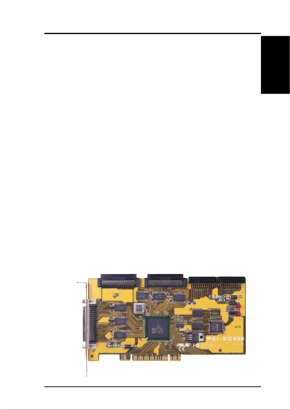
1. Introduction
Channel A 68-pin
Internal High Density
SCSI Interface (J2)
Channel A 68-pin Internal High
Density SCSI Interface (J5)
Channel B 68-pin Internal High
Density SCSI Interface (J4)
PCI-SC896 to PCI Bus
Connection on Card (J1)
Channel A 50-pin Internal Low
Density SCSI Interface
ASUS PCI-SC896 User’s Manual 9
Page 10

1. Introduction
1.2 Features
This section provides a high level overview of the PCI Interface, the SCSI
Interface, and Board Characteristics for the PCI-SC896 Host Adapter board.
1.2.1 PCI Interface
• Full 32-bit or 64-bit (33 MHz) DMA bus master
• Zero wait-state bus master data bursts
• PCI Universal 3.3 V/5 V bus support
1.2.2 SCSI Interface
• Two separate SCSI channels
• 16-bit SE/LVD
1. Introduction
• Automatically enabled termination
• One 68-pin high-density for channel A
• One 68-pin high-density for each internal channel A & B
• One 50-pin fast-SCSI connector for channel B
• Fast, Ultra, and Ultra2 data transfer capability
• SCSI TERMPWR source with autoresetting circuit breaker and
TERMPWR shorted LED for each channel
• SCSI Plug and Play
• SCAM (SCSI Configured AutoMatically). See Chapter 3, Configuring
the Host Adapter for further details about SCAM capability.
• Flash EEPROM for BIOS storage
• Serial NVRAM (Non Volatile Random Access Memory) on each chan-
nel for user configuration utility and SCAM information storage
• SCSI activity LED for each channel
1.2.3 Board Characteristics
• PCI board dimensions Approximately 9.5 x 4.0 inches
• Universal 32-bit PCI card edge connector
• ISA/EISA bracket
10 ASUS PCI-SC896 User’s Manual
Page 11

1. Introduction
1.3 Interface Descriptions
This section provides a more detailed explanation about the PCI Interface, the
SCSI Interface, the SCSI Activity LED Interface, and Wide Ultra2 SCSI.
1.3.1 The PCI Interface
PCI is a high-speed standard local bus for interfacing a number of I/O components to a PC processor and memory subsystem. The PCI functionality for the
PCI-SC896 is contained within the ASUS PCI-SC896 PCI-SCSI I/O Processor
chip. The PCI-SC896 connects directly to the PCI bus and generates timing
protocol in compliance with the PCI specification. The PCI interface operates as
a 32-bit DMA bus master. The connection is made through the edge connector
J1. The signal definitions and pin numbers conform to the PCI Local Bus Specification Revision 2.1 standard. The PCI-SC896 conforms to the PCI universal
signaling environment for a 5 V or 3.3 V PCI bus.
1.3.2 The SCSI Interface
The SCSI functionality for the PCI-SC896 is contained within the ASUS PCISC896 PCI-SCSI I/O Processor chip. The PCI-SC896 connects directly to the
two SCSI buses for SE or LVD SCSI applications and generates timing and
protocol in compliance with the SCSI standard. Each SCSI interface operates
at a burst transfer rate of up to 40 Mbyte per second for wide single-ended
transfers, and up to 80 Mbyte per second for wide LVD SCSI transfers.
1. Introduction
The SCSI interfaces on the PCI-SC896 operates as two 16-bit, synchronous or
asynchronous, single-ended or LVD, and supports Ultra2 SCSI protocols and
16-bit arbitration. The PCI-SC896 board provides autosensing, dual mode SE/
L VD SCSI termination. T ermination is normally enabled. When a SCSI device
is sensed to be connected to both internal and external connectors, termination
for that channel is automatically disabled. The PCI-SC896 supplies SCSI bus
TERMPWR (termination power) through a blocking diode and self-resetting
1.5 A short circuit protection device. An on-board LED lights up when
TERMPWR is shorted and turns off. A 40 MHz oscillator is installed on the
PCI-SC896 board to provide the clock frequency to the PCI-SC896 that is
necessary to support Wide Ultra2 SCSI transfers of up to 80 Mbytes/s.
ASUS PCI-SC896 User’s Manual 11
Page 12

1. Introduction
1. Introduction
1.3.4 Wide Ultra2 SCSI
The PCI-SC896 has full support for Wide Ultra2 SCSI. This interface is an
extension of the SCSI-3 family of standards that expands the bandwidth of the
SCSI bus to allow faster synchronous data transfers, up to 80 Mbytes/s. W ide
Ultra2 SCSI provides a doubling of the data rate over the Ultra2 SCSI interface, while it increases cable lengths and allows a larger number of devices on
the cable than Ultra2 SCSI interfaces. Special SCSI cables are specified for
operation with W ide Ultra and Ultra2 SCSI devices, and you must consider the
total number of devices and the length of your SCSI bus when setting up your
system. See Chapter 2, Installing the PCI-SC896 Host Adapter for a detailed
explanation of SCSI bus connections.
When you purchased the PCI-SC896 host adapter kit, the cable provided in the
kit is matched for a Fast/Ultra/Ultra2 SE or L VD operation. This cable also has
built-in L VD termination since most Ultra2 hard disk drives are not made with
onboard LVD termination.
Standard Cables
Maximum Bus Length (1)
STA Term Single-Ended LVD Maximum Devices
Wide Ultra SCSI 1.5M (3) 8
Wide Ultra SCSI 3.0M (3) 4
Wide Ultra2 SCSI (2) 12 16
(1)This parameter may be exceeded in point to point and engineered appli-
cations.
(2)Single-ended and high-power differential are not defined at Ultra2 speeds.
(3)LVD was not defined in the original SCSI standards for this speed. If all
devices on the bus support LVD, then 12-meter operation is possible at
this speed. However, if any device on the bus is single-ended only, then
the entire bus switches to single-ended mode, and the distances in the
single-ended column apply.
12 ASUS PCI-SC896 User’s Manual
Page 13

2. Installation
2. Installing the PCI-SC896 Host Adapter
This chapter provides instructions on how to install the PCI-SC896 Host Adapter
and includes these topics:
• Section 2.1, “Quick Installation Procedure”
• Section 2.2, “Detailed Installation Procedure”
• Section 2.3, “SCSI Bus Termination”
• Section 2.4, “Setting Interrupts”
• Section 2.5, “Completing Your Installation”
2.1 Quick Installation Procedure
This section provides quick setup instructions for the experienced computer
user with prior host adapter installation and SCSI bus setup experience. If you
prefer more detailed guidance in installing the PCI-SC896 host adapter, please
follow the instructions in the section: Section 2.2, “Detailed Installation Procedure”. For safe and proper installation, check the user’s manual that was sup-
plied with your computer and perform the following steps.
2. Installation
1. Ground yourself before removing this host adapter board. Remove the
PCI-SC896 Dual Channel PCI to Ultra2 SCSI Host Adapter board from
the packing and check that it is not damaged.
2. Remove the cabinet cover on your computer to access the PCI slots.
Refer to the user’s manual for your computer.
CAUTION: Ground yourself by touching a metal surface before handling boards. Static charges on your body can damage electronic components. Handle plug-in boards by the edge; do not touch board components or gold connector contacts. The use of a static ground strap is
recommended.
3. Locate the slots for PCI plug-in board installation. Refer to the user ’s
manual for your computer to confirm the location of the PCI slots. The
PCI-SC896 requires a PCI slot that allows bus master operation.
4. Remove the blank panel on the back of the computer aligned with the
PCI slot that you intend to use. Save the bracket screw.
ASUS PCI-SC896 User’s Manual 13
Page 14

2. Installation
5. Carefully insert the edge connector J1 of the host adapter into the PCI
slot. Make sure the edge connector is properly engaged before pressing
the board into place.
NOTE: You may notice that the components on a PCI host adapter face
the opposite way from those on other non-PCI plug-in boards you have in
your system. This is corr ect, and the board is keyed to go in only one way.
2. Installation
6. The bracket around the connector J2 should fit where the blank panel
was removed. Secure it with the bracket screw before making the internal and external SCSI bus connections.
7. If you are connecting any internal SCSI devices, plug a 68-pin connector
on the end of the internal SCSI ribbon cable into the connector J4 or J5.
Make certain to match pin-1 on both connectors. Chain your internal
devices on this cable.
8. Connect your computer’s LED cable if desired. This LED cable drives
the front panel LED found on most PC cabinets to indicate activity on
the SCSI bus.
9. Replace the cabinet cover as described in the user’s manual for your
computer.
10.Make all external SCSI bus connections.
REMEMBER: The SCSI bus requires proper termination and no duplicate SCSI IDs.
11.Finally, refer to the PCI SCSI Device Management System SDMS 4.0
User’s Guide (or the guide for the software that you will use) to load the
driver software for your particular operating system.
14 ASUS PCI-SC896 User’s Manual
Page 15

2. Installation
2.2 Detailed Installation Procedure
This section provides step-by-step instructions for installing your PCI-SC896
host adapter and connecting it to your SCSI peripherals. If you are experienced
in these tasks, you may prefer to use the preceding Section 2.1, “Quick Installation Procedure.” If you are not confident that you can perform the tasks as
described here, ASUS suggests getting assistance.
2.2.1 Before You Start
Before you start, look through the task list below to get an overall idea of the
steps to perform.
• Open your PC cabinet and select an open PCI slot
• Insert your host adapter
• Connect your SCSI peripherals
- Internal
- External
• Terminate the SCSI bus
• Set the peripheral SCSI IDs
• Make any configuration changes
• Close your PC cabinet
• Install your software
The SCSI host adapter acts on your computer’s behalf as the host to your suite
of SCSI peripherals. Each chain of SCSI peripheral devices and their host
adapter work together, and they are referred to as a SCSI bus. Each channel on
your SCSI host adapter can act as host for up to 15 peripheral devices (depending on the SCSI bus speed), not including the adapter itself.
2. Installation
ASUS PCI-SC896 User’s Manual 15
Page 16

2.2.2 Inserting Your Host Adapter
For safe and proper installation, check the user’s manual supplied with your
computer and perform the following steps:
1. Ground yourself before removing this host adapter board. Remove the
PCI-SC896 Dual Channel PCI to Ultra2 SCSI Host Adapter board from
the packing and check that it is not damaged.
2. Installation
2. Switch off and unplug power cords for all components in your system.
3. Remove the cabinet cover on your computer to access the PCI slots. Refer
to the user’s manual for your computer to find out how this is done.
CAUTION: Ground yourself by touching a metal surface before removing the cabinet cover . Static charges on your body can damage electronic components. Handle plug-in boards by the edge; do not touch
board components or gold connector contacts. The use of a static ground
strap is recommended.
2. Installation
4. Locate the slots for PCI plug-in board installation. Refer to the user ’s
manual for your computer to confirm the location of the PCI slots. The
PCI-SC896 requires a PCI slot that allows bus master operation.
5. Remove the blank panel on the back of the computer aligned with the
PCI slot that you intend to use. Save the bracket screw.
6. Carefully insert the edge connection J1 of the host adapter into the PCI
slot. Make sure the edge connector is properly engaged before pressing
the board into place.
NOTE: You may notice that the components on a PCI host adapter face
the opposite way from those on other non-PCI adapter boards you have in
your system. This is corr ect, and the board is keyed to go in only one way.
7. The bracket around the connector J2 should fit where you removed the
blank panel. Secure it with the bracket screw before making the internal
and external SCSI bus connections.
16 ASUS PCI-SC896 User’s Manual
Page 17

2. Installation
2.2.3 Connecting Your SCSI Peripherals
All internal SCSI bus connections to the PCI-SC896 host adapter are made
with an unshielded, 68-conductor ribbon cable. One side of this cable is marked
with a color to indicate the pin-1 side. The connectors on this cable are keyed
to ensure proper pin-1 connection. Use Ultra/Ultra2 rated cables for these bus
speeds.
All external SCSI bus connections to the PCI-SC896 host adapter are made
with shielded, 68-conductor cables. The connectors on this cable are always
keyed to ensure proper pin-1 connection. Some internal cables come with a
SE/LVD on one end. This end should be furthest from the host adapter.
2.2.4 Making Internal SCSI Bus Connections
This section provides step-by-step instructions about making internal SCSI
bus connections:
1. To connect an internal SCSI device, plug the 68-pin connector on one
end of a wide internal SCSI ribbon cable into the connection J4 or J5.
2. Plug the 68-pin connector on the other end of the internal SCSI ribbon
cable into the SCSI connector on the internal SCSI device. Pin-1 must
match on all connections.
3. To plug in additional internal SCSI devices, use an internal SCSI ribbon
cable with the required number of connectors attached along its length.
Make sure to match pin-1 on all connections.
4. Most PC cabinets are designed with a front panel LED, which may already be connected to an existing IDE controller. You may connect this
LED cable to your SCSI host adapter. This connection causes the front
panel LED to indicate activity on the SCSI bus.
2. Installation
An LED is also on the PCI-SC896 host adapter, which indicates activity on the
SCSI bus. The Busy LED connector J6 is not keyed. The J6 connector is a 4pin one row right angle header for both channel A and channel B. Some LED
cables have only two wires. In this case, place the connector on one end of J6.
If the LED does not light during SCSI bus activity from this host adapter, you
may have to rotate the LED cable 180° on J6.
ASUS PCI-SC896 User’s Manual 17
Page 18

2.2.5 Making External SCSI Bus Connections
This section provides step-by-step instructions about making external SCSI
bus connections:
1. If you need to connect external SCSI devices to the PCI-SC896 host
adapter, plug the 68-pin high-density connector on one end of a shielded
external high density cable into the host adapter connector J2.
2. Installation
2. Plug the 68-pin connector on the other end of the shielded external SCSI
cable into the SCSI connector on your external SCSI device.
3. If you need to connect more than one external SCSI device to your host
adapter, chain them together with shielded external SCSI cables.
2.3 SCSI Bus Termination
2. Installation
The devices that make up the SCSI bus are connected serially (chained together)
with SCSI cables. The first and last physical SCSI devices connected on the ends
of the SCSI bus must have a set of resistors called terminators. All other SCSI
devices on the bus must have their terminators removed or disabled.
REMEMBER: The PCI-SC896 host adapter is also on the SCSI bus,
and its termination is automatically enabled when it is connected to the
end of the bus.
Low-voltage differential peripheral devices are normally terminated with external terminators, but are sometimes set with jumpers or with a switch on the
peripheral. Refer to the peripheral manufacturer’s instructions and to the user’s
manual for your computer for information on how to identify the terminator
setting of each device and how to change it.
CAUTION: The auto-enable/disable sensing feature on the PCI-SC896
may enable termination erroneously if it is directly cabled to another
SCSI device or host adapter using the same sensing method. The PCISC896 senses SCSI devices by detecting the ground signal on conductor 50 of a 68-conductor SCSI cable.
When connecting another host adapter to a connector, termination must be
disabled on the board that is not at the end of the bus through software control.
18 ASUS PCI-SC896 User’s Manual
Page 19

2. Installation
The PCI-SC896 automatically controls SCSI bus termination for three different bus configurations, depending on the use of connectors. The three bus configurations are:
• Only for internal SCSI connections,
• Only for external SCSI connections, and
• Connections to both internal and external SCSI connectors.
2.3.1 Internal SCSI Connections
If only internal SCSI device connections on your host adapter have been made,
then terminate the last internal device on the SCSI bus. You must disable the
termination on all other devices. Termination on the PCI-SC896 host adapter
is automatically enabled in this case.
2.3.2 External SCSI Connections
2. Installation
If only external SCSI device connections to your host adapter have been made,
then terminate the last external device on the SCSI bus. You must disable the
termination on all other devices. T ermination on your host adapter is automatically enabled in this case.
2.3.3 Internal and External SCSI Connections
If internal and external SCSI devices are connected to your host adapter, then
terminate the last internal and external devices on the SCSI bus. You must
disable the termination on all other devices. Termination on your host adapter
is automatically disabled in this case.
NOTE: If an internal connection to another PCI-SC896 host adapter
has been made, or any connection to a device that uses the same sensing
method for automatic termination as your PCI-SC896, you must override the termination for that channel through software control.
ASUS PCI-SC896 User’s Manual 19
Page 20

2.3.4 Setting SCSI IDs
You must set each SCSI device and the host adapter to a separate SCSI ID, 0
through 15 for a 16-bit SCSI. SCSI ID 7 is the preset host adapter setting, giving
it the highest priority on the SCSI bus. If you plan to boot your computer from a
hard disk drive on the SCSI bus, that drive should have SCSI ID 0, or the lowest
SCSI ID on the bus. Chapter 3, Configuring the Host Adapter explains how to set
2. Installation
your host adapter ID using the ASUS SCSI Configuration Utility. The peripheral
device SCSI IDs are usually set with jumpers or with a switch on the peripheral.
Refer to the peripheral manufacturer’s instructions and to the user’s manual for
your computer to determine the ID of each device and how to change it. You
must have no duplication of SCSI IDs on a SCSI bus.
NOTE: As SCAM support is OFF by default for the PCI-SC896, you
may choose to turn this ON to assist in assigning SCSI IDs.
Determine the SCSI ID of each device on the SCSI bus. Note any duplications.
Make any necessary changes to the SCSI IDs and record the IDs for future
reference. The following table is provided as a place to keep this record.
2. Installation
SCSI ID Record
SCSI ID SCSI Device Channel A SCSI Device Channel B
15
14
13
12
11
10
09
08
07
06
05
04
03
02
01
00
2.4 Setting Interrupts
Normally , you do not change the default interrupt routing for the PCI-SC896,
since performance is usually increased by having two separate interrupts.
20 ASUS PCI-SC896 User’s Manual
Page 21

2. Installation
3. Configuring the Host Adapter
This chapter discusses how to change configuration settings and
includes these topics:
• Section 3.1, “When to Configure the PCI-SC896 Host Adapter”
• Section 3.2, “Starting the SCSI BIOS Configuration Utility”
• Section 3.3, “Exiting the SCSI BIOS Configuration Utility”
3.1 When to Configure the PCI-SC896
In most cases you should not need to change the default configuration of your
host adapter . You may decide to alter these default values if there is a conflict
between device settings, or if you need to optimize system performance.
The following tables list the configuration settings you can change. The global
settings effect your host adapter and all SCSI devices which are connected to
it. The device settings effect only individual SCSI devices.
Global Default Settings
Settings for the Host Adapter & All Devices Default Settings
SCAM Support Off
Parity Checking Enabled
Host Adapter SCSI ID 7
Scan Order Low to High (0-Max)
2. Installation
ASUS PCI-SC896 User’s Manual 21
Page 22

Device Default Settings
Settings for Individual SCSI Devices Default Settings
Synchronous T ransfer Rate (MB/Sec) 40 or 80
Data Width 16
Disconnect On
Read/Write I/O Time-Out (secs) 10
Scan for Devices at Boot Time Yes
Scan for SCSI LUNs Yes
Queue T ags Enabled
3. Configuring
3.2 Starting the SCSI BIOS Utility
3. Configuring
If you have SCSI BIOS version 4.0, and it includes the ASUS SCSI BIOS
Configuration Utility, you can change the default configuration of your SCSI
host adapters. You may decide to alter these default values if there is a conflict
between device settings or if you need to optimize system performance.
You can see the version number of your SCSI BIOS in a banner displayed on
your computer monitor during boot. If the utility is available, the following
message also appears on your monitor:
Press Ctrl-C to start ASUS Configuration Utility...
This message remains on your screen for about five seconds, giving you time
to start the utility. If you decide to press “Ctrl-C,” the message changes to:
Please wait, invoking ASUS Configuration Utility...
After a brief pause, your computer monitor displays the Main Menu of the
ASUS SCSI BIOS Configuration Utility . As NVRAM (Non Volatile Random
Access Memory) is available on the PCI-SC896 SCSI device, changes can be
made and stored using this menu driven utility.
IMPORT ANT : This utility is a powerful tool. If, while using it, you somehow disable all of your controllers, pressing Ctrl-A (or Ctrl-E on version 4.04 or later) after memory initialization during r eboot allows you
to re-enable and reconfigure.
22 ASUS PCI-SC896 User’s Manual
Page 23

3. Configuring
Not all devices detected by the Configuration utility can be controlled by the
BIOS. Devices such as tape drives and scanners require that a device driver
specific to that peripheral be loaded. This device driver is provided by the
devices manufacturer .
3.2.1 Configuration Utility Main Menu
When you start the ASUS SCSI BIOS Configuration Utility, the Main Menu
appears. This menu displays a list of up to four ASUS PCI to SCSI host adapters in your system and information about each of them. The PCI-SC896 host
adapter appears on the menu as two PCI-SC896 entries; one for each channel.
T o select an adapter, use only the arrow keys and enter key . Then, you can view
and/or change the current settings for that adapter and the SCSI devices attached to it. You can select an adapter only if Current Status is “On”. Changes
are possible since NVRAM is present on this host adapter .
Below the list of host adapters on the Main Menu display, you see eight options. They are described in detail below. If these settings are altered, the system reboots upon exit from the configuration utility using the Quit option.
3.2.1.1 Change Adapter Status
The change adapter status allows you to activate or deactivate a host adapter
and all SCSI devices attached to it. When this option is used to make a change,
the change takes place after a reboot that is automatic upon exit from the utility. To change an adapter ’s status, select it and press Enter. Then press the
Escape (Esc) key to exit from this menu.
3.2.1.2 Adapter Boot Order
The adapter boot order allows you to set the order in which host adapters will
boot when you have more than one ASUS host adapter in your system. When
this option is selected, the Boot Order menu appears:
T o change an adapter’s boot order, select it and press Enter . Y ou are then prompted
to enter the new boot sequence number . T o remove an adapter’s boot order , press
Enter again rather than entering a new sequence number. While the maximum
capacity is 32 adapters, only 0 through 3 can be assigned a boot order. If an
invalid number is entered, an error message appears. When the adapters are or dered as desired, press the Escape (Esc) key to exit from this menu.
3. Configuring
ASUS PCI-SC896 User’s Manual 23
Page 24

3.2.1.3 Additional Adapter Configuration
The additional adapter configuration allows you to configure an adapter that is
not assigned a boot order . When this option is selected, the Adapter Configuration menu appears:
Highlight the adapter to be configured and press Enter. The message “Resetting Adapter, Please wait” appears, and then the system scans for devices. Finally , the Utilities Menu appears and lists the available options, which are described below .
3.2.1.4 Display Mode
Display mode determines how much information about your host adapters and
SCSI devices appear on your computer monitor during boot. For more complete information, choose the verbose setting. For a faster boot, choose the
3. Configuring
terse setting.
3.2.1.5 Mono/Color
3. Configuring
Mono/color allows you to choose between a monochrome or color display for
the SCSI BIOS Configuration utility . You might need to choose the mono setting to get a more readable screen on a monochrome monitor .
3.2.1.6 Language
If enabled, the Language option allows you to select from five languages for
the configuration utility: English, German, French, Italian, and Spanish. Call
for support if you have any additional questions.
3.2.1.7 Help
The Help option allows you to bring up a help screen with information about
the Main Menu.
3.2.1.8 Quit
The Quit option allows you to exit from the SCSI BIOS Configuration utility
when on the Main Menu.
3.2.1.9 Esc
Pressing the Esc key allows exit from all the screens except the Main Menu.
24 ASUS PCI-SC896 User’s Manual
Page 25

3. Configuring
3.2.2 Utilities Menu
When you select a host adapter on the Main menu, the Utilities menu appears.
Choose Adapter Setup to view and change the selected adapter settings. Choose
Device Selections to view and change settings for the devices attached to the
selected adapter. You are returned to this menu after making changes to the
configuration of any host adapter or connected SCSI device. Before you exit
this menu, you are prompted to save or cancel any changes.
3.2.2.1 Adapter Setup Menu
When you select Adapter Setup, the Adapter Setup menu appears:
The settings in this menu are global settings that affect the selected host adapter
and all SCSI devices attached to it.
SCAM Support – The ASUS BIOS version 4.0 and above supports the SCSI
Plug and Play protocol called SCAM (SCSI Configured AutoMatically). SCAM
support by default is off in versions 4.11.00 and later for the PCI-SC896 device. You may choose to turn this on. Note that if this BIOS is flashed onto a
board with existing settings, then these settings will not be changed to reflect
the new BIOS defaults. Go into the Configuration Utility to change settings.
Parity – The ASUS PCI to SCSI host adapters always generate parity, but
some older SCSI devices do not. Therefore, you are offered the option of disabling parity checking.
NOTE: When disabling parity checking, it is also necessary to disable
disconnects for all devices, as parity checking for the r eselection phase
is not disabled. If a device does not generate parity , and it disconnects,
the I/O never completes because the reselection never completes.
Host SCSI ID – In general, it is suggested that you do not change your host
adapter ID from the default value of 7, as this gives it the highest priority on the
SCSI bus.
Scan Order – This option allows you to tell the SCSI BIOS and device drivers
to scan the SCSI bus from low to high (0 to max) SCSI ID, or from high to low
(max to 0) SCSI ID. If you have more than one device on the SCSI bus, changing the scan order changes the order in which drive letters are assigned by the
system. Drive order may be reassigned differently in systems supporting the
BIOS Boot Specification (BBS). See the PCI SCSI Device Management System SDMS 4.0 User’s Guide, Chapter 2 “SCSI BIOS” for additional informa-
tion regarding BBS.
3. Configuring
ASUS PCI-SC896 User’s Manual 25
Page 26

NOTE: This scan order option may conflict with operating systems that
automatically assign a drive order.
Removable Media Support – This option defines the removable media sup-
port for a specific drive. When this option is selected, a window appears with
three choices:
• None
• Boot Drive Only
• With Media Installed
None – indicates there is no removable media support whether the drive is
selected in BBS as being first, or first in scan order in non-BBS.
Boot Drive Only – provides removable media support for a removable hard
drive if it is first in the scan order .
3. Configuring
With Media Installed – provides removable media support wherever the
drive(s) actually resides. One of these choices can be selected by highlighting
it and pressing Enter .
3. Configuring
CHS Mapping – This option defines the cylinder head sector (CHS) values
that will be mapped onto a disk without pre-existing partitioning information.
SCSI Plug and Play Mapping is the default value. T o support interchange with
noncompatible systems, there is another option that can be selected by choosing CHS Mapping and then cursoring to “Alternate CHS Mapping”.
NOTE: Neither of these options will have any affect after the disk has
been partitioned with the FDISK command. To remove partitioning,
two options are available:
• Reformat the disk using the Format Device option. See the section “Section 3.2.3, “Device Selections Menu”” below.
• Use the FDISK /MBR command at the C:\ prompt, where MBR represents master boot record.
IMPORTANT: Reformatting the disk or using FDISK /MBR erases all
partitioning and data that exists. Be careful when using either the Format utility or the FDISK /MBR command that you target the correct
disk. After clearing the partitions and data, it is necessary to reboot
and clear memory or the old partitioning data will be r eused, thus nullifying the previous operation.
26 ASUS PCI-SC896 User’s Manual
Page 27

3. Configuring
3.2.3 Device Selections Menu
When you select the Device Selections option, the corresponding menu appears. The settings in this menu affect individual SCSI devices attached to the
selected host adapter. Changes made from this menu do not cause the system
to reboot upon exit from the SCSI BIOS Configuration Utility. To change a
value, select the required device by using the arrow keys and press Enter. A
new menu appears providing the options and utilities available. For example,
you could cursor to Sync Rate to change the Sync Rate value of the chosen
device.
Sync Rate (Mbytes/s) – The value set with this option defines the maximum
data transfer rate the host adapter attempts to negotiate. The host adapter and a
SCSI device must agree to a rate they can both handle.
Width (bits) – The value set with this option defines the maximum SCSI data
width the host adapter attempts to negotiate. The host adapter and a SCSI device must agree to a width they can both handle. Only host adapters that can do
16-bit data transfers have this option enabled.
Disconnect – SCSI devices have the ability to disconnect from the initiator
during an I/O transfer. This disconnect frees the SCSI Bus to allow other I/O
processes. This option tells the host adapter whether or not to allow a device to
disconnect. Some devices run faster with disconnects enabled (mostly newer
devices), while some run faster with disconnects disabled (mostly older devices).
Read/Write I/O Time-out (seconds) – This option sets the amount of time
the host adapter waits for a read, write, or seek command to complete before
trying the I/O transfer again. Since this provides a safeguard allowing the system to recover if an I/O operation fails, it is recommended that you always set
the time-out to a value greater than zero.
NOTE: If the time-out is set to zero, then the I/O will never time-out.
Scan for Device at Boot T ime – When there is a device you do not want to be
available to the system, set this option to “No” for that device. Also, on a bus
with only a few devices attached, you can speed up boot time by changing this
setting to “No” for all unused SCSI IDs.
3. Configuring
Scan for SCSI Logical Units (LUNs) – Y ou can set this option to “No” if you
have problems with a device that responds to all LUNs whether they are occupied or not. For example, if there is a SCSI device with multiple LUNs but you
do not want all of those LUNs to be available to the system, then set this option
to “No.” This will limit the scan to LUN0 only.
ASUS PCI-SC896 User’s Manual 27
Page 28

Queue T ags – This option allows you to enable or disable the issuing of queue
tags during I/O requests when your device driver can do this.
Format Device – If enabled, this option allows you to low-level format a
magnetic disk drive. Low-level formatting will completely and irreversibly
erase all data on the drive. Note that this utility will only format 512 byte
sectors. For other sector sizes, do not use this utility.
Verify – This option allows you to read all the sectors on a disk looking for
errors. When selected, this option displays the following message:
“Verify all sectors on the device
Press ESC to abort
Else press any key to continue”
Help – This option brings up a help screen with information about the current
3. Configuring
menu.
3. Configuring
Restore Default Setup – This option resets all device selections back to their
optimal settings. Select this option to restore all manufacturing defaults for the
specified adapter . Note that all user customized options will be lost upon saving after restoring default setup.
Exit this menu – This option allows you to leave the current menu screen and
return to the previous screen.
3.3 Exiting the SCSI BIOS Utility
Since some changes only take effect after your system reboots, it is important
that you exit this configuration utility properly. Return to the Main Menu and
exit by using the Quit option.
IMPORTANT: If you reboot the system without properly exiting the
utility, some changes may not take effect.
28 ASUS PCI-SC896 User’s Manual
Page 29

4. Appendix
4. Glossary of Terms and Abbreviations
Address - A specific location in memory, designated either numerically or by
a symbolic name.
Asynchronous Data Transfer - A method of transmission which does not
require a common clock, but separates fields of data by stop and start bits. It is
slower than synchronous data transfer .
BIOS - Basic Input/Output System. Software that provides basic read/write
capability. Usually kept as firmware (ROM based). The system BIOS on the
mainboard of a computer is used to boot and control the system. The SCSI
BIOS on your host adapter acts as an extension of the system BIOS.
Bit - A binary digit. The smallest unit of information a computer uses. The
value of a bit (0 or 1) represents a two-way choice, such as on or off, true or
false, and so on.
Bus - A collection of unbroken signal lines across which information is transmitted from one part of a computer system to another . Connections to the bus
are made via taps on the lines.
Bus Mastering - A high-performance way to transfer data. The host adapter
controls the transfer of data directly to and from system memory without bothering the computer’s microprocessor. This is the fastest way for multitasking
operating systems to transfer data.
Byte - A unit of information consisting of eight bits.
Chain - A topology in which every processor is connected to two others, ex-
cept for two end processors that are connected to only one other.
CISPR - A special international committee on radio interference (Committee,
International and Special, for Protection in Radio). B-2 Glossary of T erms and
Abbreviations
Configuration - Refers to the way a computer is set up; the combined hardware components (computer, monitor, keyboard, and peripheral devices) that
make up a computer system; or the software settings that allow the hardware
components to communicate with each other .
4. Appendix
CPU - Central Processing Unit. The “brain” of the computer that performs the
actual computations. The term Micro Processor Unit (MPU) is also used.
DMA - Direct Memory Access. A method of moving data from a storage device directly to RAM, without using the CPU’s resources.
ASUS PCI-SC896 User’s Manual 29
Page 30

4. Appendix
DMA Bus Master - A feature that allows a peripheral to control the flow of
data to and from system memory by blocks, as opposed to PIO (Programmed
I/O) where the processor is in control and the flow is by byte.
Device Driver - A program that allows a microprocessor (through the operating system) to direct the operation of a peripheral device.
Differential - A hardware configuration for connecting SCSI devices. It uses a
pair of lines for each signal transfer (as opposed to single-ended SCSI which
references each SCSI signal to a common ground).
Dword - A double word is a group of 4 consecutive bytes or characters that are
stored, addressed, transmitted, and operated on as a unit. The lower two address bits of the least significant byte must equal zero in order to be dword
aligned.
EEPROM - Electronically-Erasable Programmable Read Only Memory. A
memory chip typically used to store configuration information. See NVRAM.
EISA - Extended Industry Standard Architecture. An extension of the 16-bit
ISA bus standard. It allows devices to perform 32-bit data transfers.
External SCSI Device - A SCSI device installed outside the computer cabinet. These devices are connected in a continuous chain using specific types of
shielded cables.
4. Appendix
Fast SCSI - A standard for SCSI data transfers. It allows a transfer rate of up to 10
Mbytes/s over an 8-bit SCSI bus and up to 20 Mbytes/s over a 16-bit SCSI bus.
FCC - Federal Communications Commission.
File - A named collection of information stored on a disk.
Firmware - Software that is permanently stored in ROM. Therefore, it can be
accessed during boot time.
Hard Disk - A disk made of metal and permanently sealed into a drive car-
tridge. A hard disk can store very large amounts of information.
Host - The computer system in which a SCSI host adapter is installed. It uses
the SCSI host adapter to transfer information to and from devices attached to
the SCSI bus.
Host Adapter - A circuit board or integrated circuit that provides a SCSI bus
connection to the computer system.
Internal SCSI Device - A SCSI device installed inside the computer cabinet. These
devices are connected in a continuous chain using an unshielded ribbon cable.
30 ASUS PCI-SC896 User’s Manual
Page 31

4. Appendix
IRQ - Interrupt Request Channel. A path through which a device can get the
immediate attention of the computer’s CPU. The PCI bus assigns an IRQ path
for each SCSI host adapter .
ISA - Industry Standard Architecture. A type of computer bus used in most
PC’s. It allows devices to send and receive data up to 16-bits at a time.
Kbyte - Kilobyte. A measure of computer storage equal to 1024 bytes.
Local Bus - A way to connect peripherals directly to computer memory. It
bypasses the slower ISA and EISA busses. PCI is a local bus standard.
Logical Unit - A subdivision, either logical or physical, of a SCSI device (ac-
tually the place for the device on the SCSI bus). Most devices have only one
logical unit, but up to eight are allowed for each of the eight possible devices
on a SCSI bus.
LUN - Logical Unit Number . An identifier, zero to seven, for a logical unit.
LVD - Low-Voltage Differential. LVD is a robust design methodology that im-
proves power consumption, data integrity , cable lengths and support for multiple
devices, while providing a migration path for increased I/O performance.
Mbyte - Megabyte. A measure of computer storage equal to 1024 kilobytes.
Main Memory - The part of a computer’s memory which is directly acces-
sible by the CPU (usually synonymous with RAM).
Motherboard (Mainboard ) - A large circuit board that holds RAM, ROM,
the microprocessor, custom integrated circuits, and other components that make
a computer work. It also has expansion slots for host adapters and other expansion boards.
Multi-tasking - The executing of more than one command at the same time.
This allows programs to operate in parallel.
Multi-threading - The simultaneous accessing of data by more than one SCSI
device. This increases the data throughput.
NVRAM - Non V olatile Random Access Memory. Actually an EEPROM (Electronically-Erasable Programmable Read Only Memory chip) used to store configuration information. See EEPROM.
4. Appendix
Operating System - A program that organizes the internal activities of the
computer and its peripheral devices. An operating system performs basic tasks
such as moving data to and from devices, and managing information in memory .
It also provides the user interface.
ASUS PCI-SC896 User’s Manual 31
Page 32

4. Appendix
Parity Checking - A way to verify the accuracy of data transmitted over the
SCSI bus. One bit in the transfer is used to make the sum of all the 1 bits either
odd or even (for odd or even parity). If the sum is not correct, an error message
appears.
PCI - Peripheral Component Interconnect. A local bus specification that allows connection of peripherals directly to computer memory. It bypasses the
slower ISA and EISA busses.
Peripheral Devices - A piece of hardware (such as a video monitor , disk drive,
printer, or CD-ROM) used with a computer and under the computer’s control.
SCSI peripherals are controlled through a SCSI host adapter .
Pin-1 Orientation - The alignment of pin-1 on a SCSI cable connector and the
pin-1 position on the SCSI connector into which it is inserted. External SCSI
cables are always keyed to insure proper alignment, but internal SCSI ribbon
cables are sometimes not.
PIO - Programmed Input/Output. A way the CPU can transfer data to and from
memory via the computer’s I/O ports. PIO is usually faster than DMA, but
requires CPU time.
Port Address - Also Port Number . The address through which commands are
sent to a host adapter board. This address is assigned by the PCI bus.
4. Appendix
Port Number - See Port Address.
Queue Tags - A way to keep track of multiple commands that allows for in-
creased throughput on the SCSI bus.
RAM - Random Access Memory. The computer’s primary working memory
in which program instructions and data are stored and are accessible to the
CPU. Information can be written to and read from RAM. The contents of RAM
are lost when the computer is turned off.
RISC Core - ASUS SCSI chips contain a RISC (Reduced Instruction Set Computer) processor, programmed through microcode scripts.
ROM - Read Only Memory. Memory from which information can be read but not
changed.The contents of ROM are not erased when the computer is turned off.
SCAM - SCSI Configured AutoMatically . A method to automatically allocate
SCSI IDs via software when SCAM compliant SCSI devices are attached.
SCSI - Small Computer System Interface. A specification for a high performance peripheral bus and command set. The original standard is referred to as
SCSI-1.
32 ASUS PCI-SC896 User’s Manual
Page 33

4. Appendix
SCSI-2 - The current SCSI specification which adds features the original SCSI1 standard.
SCSI-3 - The next SCSI specification, which adds features to the SCSI-2 standard. Although this version is still in development, parts of the SCSI-3 standard are already in use.
SCSI Bus - A host adapter and one or more SCSI peripherals connected by
cables in a linear chain configuration. The host adapter may exist anywhere on
the chain, allowing connection of both internal and external SCSI devices. A
system may have more than one SCSI bus by using multiple host adapters.
SCSI Device - Any device that conforms to the SCSI standard and is attached
to the SCSI bus by a SCSI cable. This includes SCSI host adapters and SCSI
peripherals.
SCSI ID - A way to uniquely identify each SCSI device on the SCSI bus. Each
SCSI bus has eight available SCSI IDs numbered 0 through 7 (or 0 through 15
for W ide SCSI). The host adapter usually gets ID 7 giving it priority to control
the bus.
SDMS - SCSI Device Management System. An ASUS software product that
manages SCSI system I/O.
STA - SCSI Trade Association. A group of companies that cooperate to promote SCSI parallel interface technology as a viable mainstream I/O interconnect for commercial computing.
Single-Ended SCSI - A hardware specification for connecting SCSI devices.
It references each SCSI signal to a common ground. This is the most common
method (as opposed to differential SCSI which uses a separate ground for each
signal).
Synchronous Data Transfer - One of the ways data is transferred over the
SCSI bus. Transfers are clocked with fixed-frequency pulses. This is faster
than asynchronous data transfer. Synchronous data transfers are negotiated
between the SCSI host adapter and each SCSI device.
System BIOS - Controls the low level POST (Power On Self Test), and basic
operation of the CPU and computer system.
4. Appendix
T ermination - The electrical connection required at each end of the SCSI bus,
composed of a set of resisters. It improves the integrity of bus signals.
ASUS PCI-SC896 User’s Manual 33
Page 34

4. Appendix
Ultra SCSI - A standard for SCSI data transfers. It allows a transfer rate of up
to 20 Mbytes/s over an 8-bit SCSI bus and up to 40 Mbytes/s over a 16-bit
SCSI bus. ST A (SCSI Trade Association) supports using the term “Ultra SCSI”
over the term “Fast-20”.
Ultra2 SCSI - A standard for SCSI data transfers. It allows a transfer rate of up
to 40 Mbytes/s over an 8-bit SCSI bus, and up to 80 Mbytes/s over a 16-bit
SCSI bus. ST A (SCSI Trade Association) supports using the term “Ultra2 SCSI”
over the older term “Fast-40”.
VCCI - Voluntary Control Council for Interference.
VHDCI - Very High Density Cable Interconnect. A trapezoidal shielded con-
nector that has a 0.8 mm pitch.
Wide SCSI - A SCSI-2 feature allowing 16 or 32-bit transfers on the SCSI
bus. This dramatically increases the transfer rate over the standard 8-bit SCSI
bus.
Wide Ultra SCSI - The STA term for SCSI bus width 16 bits, SCSI bus speed
maximum data rate 40 Mbytes/s.
Wide Ultra2 SCSI - The STA term for SCSI bus width 16 bits, SCSI bus
speed maximum data rate 80 Mbytes/s.
4. Appendix
W ord A two byte (or 16-bit) unit of information.
34 ASUS PCI-SC896 User’s Manual
 Loading...