

Page 1
RS120-E5/PA2
1U Rackmount Barebone Server
User Guide
Page 2

E3434
First Edition V1
October 2007
Copyright © 2007 ASUSTeK COMPUTER INC. All Rights Reserved.
No part of this manual, including the products and software described in it, may be reproduced, transmitted,
transcribed, stored in a retrieval system, or translated into any language in any form or by any means,
except documentation kept by the purchaser for backup purposes, without the express written permission
of ASUSTeK COMPUTER INC. (“ASUS”).
ASUS provides this manual “as is” without warranty of any kind, either express or implied, including but not
limited to the implied warranties or conditions of merchantability or tness for a particular purpose. In no
event shall ASUS, its directors, ofcers, employees, or agents be liable for any indirect, special, incidental,
or consequential damages (including damages for loss of prots, loss of business, loss of use or data,
interruption of business and the like), even if ASUS has been advised of the possibility of such damages
arising from any defect or error in this manual or product.
Specications and information contained in this manual ae furnished for informational use only, and are
subject to change at any time without notice, and should not be construed as a commitment by ASUS.
ASUS assumes no responsibility or liability for any errors or inaccuracies that may appear in this manual,
including the products and software described in it.
Product warranty or service will not be extended if: (1) the product is repaired, modied or altered, unless
such repair, modication of alteration is authorized in writing by ASUS; or (2) the serial number of the
product is defaced or missing.
Products and corporate names appearing in this manual may or may not be registered trademarks or
copyrights of their respective companies, and are used only for identication or explanation and to the
owners’ benet, without intent to infringe.
ii
Page 3

Contents
Notices ........................................................................................................ vii
Federal Communications Commission Statement ........................... vii
Canadian Department of Communications Statement ..................... vii
Safety information
Electrical Safety .............................................................................. viii
Operation Safety ............................................................................. viii
About this guide
Chapter 1: Product introduction
1.1 System package contents ........................................................... 1-2
1.2 Systemspecications
1.3 Front panel features
1.4 Rear panel features
1.5 Internal features
1.6 LED information
1.6.1 Rear panel LEDs .............................................................
1.6.2 Front panel LEDs ............................................................
1.6.3 LAN (RJ-45) LEDs ..........................................................
Chapter 2: Hardware setup
2.1 Chassis cover ............................................................................... 2-2
2.1.1 Removing the cover ........................................................
2.1.2 Installing the cover ..........................................................
2.2 Central Processing Unit (CPU)
2.2.1 Installing the CPU ...........................................................
2.2.2 Installing the CPU heatsink and airduct ..........................
2.3 System memory
2.3.1 DIMM sockets location ....................................................
2.3.2 Memory congurations ....................................................
2.3.3 Installing a DIMM ............................................................
2.3.4 Removing a DIMM ..........................................................
2.4 Hard disk drives
2.5 Expansion slot
2.5.1 Installing an expansion card to the riser card bracket ...
2.5.2 Reinstalling the riser card bracket .................................
2.5.3 Replacing the optional riser card ..................................
2.5.4 Conguring an expansion card .....................................
2.6 Cable connections
2.7 SATA backplane cabling
.................................................................................... viii
......................................................................................... ix
................................................................. 1-3
..................................................................... 1-5
...................................................................... 1-5
........................................................................... 1-6
........................................................................... 1-6
................................................... 2-4
........................................................................... 2-8
......................................................................... 2-10
............................................................................ 2-12
..................................................................... 2-17
............................................................ 2-18
1-6
1-7
1-7
2-2
2-3
2-4
2-6
2-8
2-8
2-9
2-9
2-12
2-14
2-15
2-16
iii
Page 4

Contents
2.8 Removable components ............................................................ 2-19
2.8.1 System fans ..................................................................
2.8.2 System fan with dummy case .......................................
2.8.3 Device fan .....................................................................
2.8.4 Power supply module ....................................................
2.8.5 Optical drive ..................................................................
2.8.6 Motherboard ..................................................................
Chapter 3: Installation options
3.1 Rackmount rail kit items .............................................................. 3-2
3.2 Rack rails assembly
3.3 Attaching the rails to the rack
3.4 Rackmounting the server
Chapter 4: Motherboard info
4.1 Motherboard layout ...................................................................... 4-2
4.2 Jumpers
4.3 Connectors
........................................................................................ 4-4
................................................................................... 4-8
Chapter 5: BIOS setup
5.1 Managing and updating your BIOS ............................................ 5-2
5.1.1 Creating a bootable oppy disk .......................................
5.1.2 AFUDOS utility ................................................................
5.1.3 ASUS CrashFree BIOS 3 utility ......................................
5.2 BIOS setup program
5.2.1 BIOS menu screen ..........................................................
5.2.2 Menu bar .........................................................................
5.2.3 Navigation keys ...............................................................
5.2.4 Menu items .....................................................................
5.2.5 Sub-menu items ..............................................................
5.2.6 Conguration elds .........................................................
5.2.7 Pop-up window ...............................................................
5.2.8 Scroll bar .........................................................................
5.2.9 General help ...................................................................
5.3 Main menu
5.3.1 System Time
5.3.2 System Date
5.3.3 Legacy Diskette A [Disabled] ........................................
5.3.4 Primary/Third/Fourth IDE Master/Slave .........................
5.3.5 IDE Conguration ..........................................................
.................................................................................. 5-10
..................................................................... 3-2
..................................................... 3-3
............................................................ 3-4
.................................................................... 5-7
[xx:xx:xx] ................................................. 5-10
[Day xx/xx/xxxx] ....................................... 5-10
2-19
2-21
2-22
2-23
2-24
2-26
5-2
5-3
5-6
5-8
5-8
5-8
5-9
5-9
5-9
5-9
5-9
5-9
5-10
5-11
5-13
iv
Page 5

Contents
5.3.6 System Information ....................................................... 5-15
5.4 Advanced menu
5.4.1 USB Conguration ........................................................
5.4.2 MPS Conguration ........................................................
5.4.3 CPU Conguration ........................................................
5.4.6 Chipset Conguration ...................................................
5.4.7 Onboard Devices Conguration ....................................
5.4.8 PCI/PnP Conguration ..................................................
5.5 Server menu
5.5.1 Remote Access Conguration .......................................
5.6 Power menu
5.6.1 ACPI APIC Support [Enabled] .......................................
5.6.2 APM Conguration ........................................................
5.6.3 Hardware Monitor .........................................................
5.7 Boot menu
5.7.1 Boot Device Priority ......................................................
5.7.2 Hard Disk Drives ...........................................................
5.7.3 Boot Settings Conguration ..........................................
5.7.4 Security .........................................................................
5.8 Exit menu
Chapter 6: RAIDConguration
6.1 Setting up RAID ............................................................................ 6-2
6.1.2 Installing hard disk drives ................................................
6.1.3 Setting the RAID item in BIOS ........................................
6.1.4 RAID conguration utilities ..............................................
6.2 LSI Logic Embedded SATA RAID Setup Utility
6.2.1 Creating a RAID 0 or RAID 1 set ....................................
6.2.2 Adding or viewing a RAID conguration ........................
6.2.3 Initializing the logical drives ..........................................
6.2.4 Rebuilding failed drives .................................................
6.2.5 Checking the drives for data consistency .....................
6.2.6 Deleting a RAID conguration .......................................
6.2.7 Selecting the boot drive from a RAID set ......................
6.2.8 Enabling the WriteCache ..............................................
®
6.3 Intel
Matrix Storage Manager Option ROM Utility ................. 6-27
6.3.1 Creating a RAID 0 set (Stripe) ......................................
6.3.2 Creating a RAID 1 set (Mirror) ......................................
6.3.3 Deleting a RAID set ......................................................
......................................................................... 5-16
............................................................................... 5-24
................................................................................ 5-26
.................................................................................. 5-29
.................................................................................... 5-33
.......................... 6-4
5-16
5-17
5-18
5-20
5-22
5-23
5-24
5-26
5-27
5-28
5-29
5-29
5-30
5-31
6-3
6-3
6-3
6-5
6-11
6-14
6-19
6-21
6-24
6-25
6-26
6-28
6-30
6-31
v
Page 6

Contents
6.3.4 Resetting disks to Non-RAID ........................................ 6-32
5.3.5 Exiting the Intel
6.4 Global Array Manager
®
Matrix Storage Manager .................... 6-32
................................................................ 6-33
Chapter 7: Driver installation
7.1 RAID driver installation ............................................................... 7-2
7.1.1 Creating a RAID driver disk ............................................
7.1.2 Installing the RAID controller driver ...............................
®
7.2 Intel
7.3 LAN driver installation
7.4 VGA driver installation
chipset software installation ........................................... 7-13
............................................................... 7-16
............................................................... 7-19
®
7.4.1 Windows
Server .......................................................... 7-19
7.5 Management applications and utilities installation
7.5.1 Running the support CD ...............................................
7.5.2 Drivers menu .................................................................
7.5.3 Management Software menu ........................................
7.5.4 Utilities menu ................................................................
7.5.5 Contact information .......................................................
................ 7-21
7-2
7-4
7-21
7-21
7-22
7-22
7-22
vi
Page 7

Notices
Federal Communications Commission Statement
This device complies with Part 15 of the FCC Rules. Operation is subject to the
following two conditions:
•
This device may not cause harmful interference, and
•
This device must accept any interference received including interference that
may cause undesired operation.
This equipment has been tested and found to comply with the limits for a
Class A digital device, pursuant to Part 15 of the FCC Rules. These limits are
designed to provide reasonable protection against harmful interference in a
residential installation. This equipment generates, uses and can radiate radio
frequency energy and, if not installed and used in accordance with manufacturer’
s instructions, may cause harmful interference to radio communications. However,
there is no guarantee that interference will not occur in a particular installation. If
this equipment does cause harmful interference to radio or television reception,
which can be determined by turning the equipment off and on, the user is
encouraged to try to correct the interference by one or more of the following
measures:
•
Reorient or relocate the receiving antenna.
•
Increase the separation between the equipment and receiver.
•
Connect the equipment to an outlet on a circuit different from that to which the
receiver is connected.
•
Consult the dealer or an experienced radio/TV technician for help.
WARNING! The use of shielded cables for connection of the monitor to the
graphics card is required to assure compliance with FCC regulations. Changes
or modications to this unit not expressly approved by the party responsible for
compliance could void the user’s authority to operate this equipment.
Canadian Department of Communications Statement
This digital apparatus does not exceed the Class A limits for radio noise emissions
from digital apparatus set out in the Radio Interference Regulations of the
Canadian Department of Communications.
This Class A digital apparatus complies with Canadian ICES-003.
This symbol of the crossed out wheeled bin indicates that the product (electrical,
electronic equipment, and mercury-containing button cell battery) should not
be placed in municipal waste. Check local regulations for disposal of electronic
products.
vii
Page 8

Safety information
Electrical Safety
• Before installing or removing signal cables, ensure that the power cables for
the system unit and all attached devices are unplugged.
• To prevent electrical shock hazard, disconnect the power cable from the
electrical outlet before relocating the system.
• When adding or removing any additional devices to or from the system, ensure
that the power cables for the devices are unplugged before the signal cables
are connected. If possible, disconnect all power cables from the existing
system before you add a device.
• If the power supply is broken, do not try to x it by yourself. Contact a qualied
service technician or your dealer.
Operation Safety
• Any mechanical operation on this server must be conducted by certied or
experienced engineers.
• Before operating the server, carefully read all the manuals included with the
server package.
• Before using the server, make sure all cables are correctly connected and the
power cables are not damaged. If any damage is detected, contact your dealer
as soon as possible.
• To avoid short circuits, keep paper clips, screws, and staples away from
connectors, slots, sockets and circuitry.
• Avoid dust, humidity, and temperature extremes. Place the server on a stable
surface.
viii
This product is equipped with a three-wire power cable and plug for the user’s
safety. Use the power cable with a properly grounded electrical outlet to avoid
electrical shock.
Lithium-Ion Battery Warning
CAUTION! Danger of explosion if battery is incorrectly replaced.
Replace only with the same or equivalent type recommended by the
manufacturer. Dispose of used batteries according to the manufacturer’s
instructions.
CD-ROM Drive Safety Warning
CLASS 1 LASER PRODUCT
Heavy System
CAUTION! This server system is heavy. Ask for assistance when moving or
carrying the system.
Page 9

About this guide
Audience
This user guide is intended for system integrators, and experienced users with at
least basic knowledge of conguring a server.
Contents
This guide contains the following parts:
1. Chapter 1: Product Introduction
This chapter describes the general features of the server, including sections
on front panel and rear panel specications.
2. Chapter 2: Hardware setup
This chapter lists the hardware setup procedures that you have to perform
when installing or removing system components.
3. Chapter 3: Installation options
This chapter describes how to install optional components into the barebone
server.
4. Chapter 4: Motherboard information
This chapter gives information about the motherboard that comes with the
server. This chapter includes the motherboard layout, jumper settings, and
connector locations.
5. Chapter 5: BIOS information
This chapter tells how to change system settings through the BIOS Setup
menus and describes the BIOS parameters.
6. Chapter6:RAIDconguration
This chapter tells how to change system settings through the BIOS Setup
menus. Detailed descriptions of the BIOS parameters are also provided.
7 Chapter 7: Driver installation
This chapter provides instructions for installing the necessary drivers for
different system components.
ix
Page 10

Conventions used in this guide
To make sure that you perform certain tasks properly, take note of the following
symbols used throughout this manual.
DANGER/WARNING:
when trying to complete a task.
CAUTION:
when trying to complete a task.
IMPORTANT:
task.
NOTE:
task.
Information to prevent damage to the components
Instructions that you MUST follow to complete a
Tips and additional information to help you complete a
Information to prevent injury to yourself
Typography
Bold text Indicates a menu or an item to select.
Italics
Used to emphasize a word or a phrase.
<Key> Keys enclosed in the less-than and greater than sign means that you must press the
enclosed key.
Example: <Enter> means that you must press
the Enter or Return key.
<Key1+Key2+Key3> If you must press two or more keys
simultaneously, the key names are linked with
a plus sign (+).
Example: <Ctrl+Alt+D>
Command
exactly as shown, then supply the required
item or value enclosed in brackets.
Example: At the DOS prompt, type the
command line:
Means that you must type the command
format A:/S
References
Refer to the following sources for additional information, and for product and
software updates.
1. ASUS Server Web-based Management (ASWM) user guide
This manual tells how to set up and use the proprietary ASUS server
management utility.
2. ASUS websites
The ASUS websites worldwide provide updated information for all ASUS
hardware and software products. Refer to the ASUS contact information.
x
Page 11

Chapter 1
This chapter describes the general
features of the chassis kit. It includes
sections on front panel and rear panel
specications.
ASUS RS120-E5/PA2
Product introduction
1-
Page 12

1.1 System package contents
Check your package for the following standard items.
1. ASUS R10 1U rackmount chassis with:
• ASUS P5BV-R motherboard
• 315 W single power supply
• SATA backplane with 2 x SATA cables
• PCI Express x8 and PCI Express x4 riser assembly
• Front I/O board (ASUS FPB-AR14)
• 4 x system fans (4 x 28 mm)
• 2 x hot-swap HDD trays
• Pre-connected device/power cables
2. 1 x bag of screws
3. 1 x RS120-E5 drivers and utilities CD (including ASWM)
4. 2 x User guide
• RS120-E5/PA2 user guide
• ASUS ASWM 2.0 user guide
5. Rail kit
Contact your dealer immediately if any of the items is damaged or missing.
* The system does not include a USB oppy drive. You may have to use a USB
oppy drive when creating a SATA RAID driver disk. Refer to Chapter 7 for
details.
Chapter 1: Product introduction1-2
Page 13
1.2 Systemspecications
The ASUS RS120-E5/PA2 is a 1U barebone server system featuring the ASUS
P5BV-R motherboard. The server supports the Intel® Xeon 3000/Wolfdale
Series and Xeon 3200 (G-0)/Yorkeld Series processor in the LGA775 package,
and includes the latest technologies through the chipsets embedded on the
motherboard.
Model Name RS120-E5/PA2
Processor
System Bus
Core Logic
ASUS Features Smart Fan
ASWM2.0
Memory Total Slots
Capacity
Memory Type
Memory Size
Expansion Slots Total PCI/PCI-X/
PCI-E Slots
Slot Type
Additional Slot 1
Storage SATA Controller
HDD Bays I = internal
A or S will be hot-
swappable
Networking LAN
Graphic VGA
Auxiliary Storage FDD / CD / DVD
Onboard I/O
(continued on the next page)
ASUS RS120-E5/PA2 1-3
1 * Socket LGA775
Dual-Core Intel® Xeon® processor 3000/
Wolfdale sequence
Quad-Core Intel® Xeon® processor 3200 (G-0)/
Yorkeld sequence
FSB 800/1066/1333
Intel® 3200 MCH
Intel® ICH7R
Smart Fan III
�
4 (2-channel)
Maximum up to 8GB*
DDR2 667/800 Unbuffered , ECC
512 MB, 1 GB, 2GB*
2
1 * PCI-E x 16 slot(x8 link) (Full-Height / HalfLength)+1 *PCI-E x 8 slot(x4 link) (Full-Height /
Half-Length) (Default) or
1 * PCI-E x 8 slot(x8 link) (Full-Height / Half-
Length)+1 * PCI-X 64-bit/133MHz slot (Full-
Height / Half-Length) (Option)
1* SO-DIMM socket for optional ASMB3-SOL or
ASMB3-iKVM
Intel® ICH7R:
2 SATA2 300MB/s ports
Intel Matrix Storage (Windows only)
(Support software RAID 0 and 1)
LSI MegaRAID (Linux/Windows)
(Support software RAID 0 and 1)
2 * Hot-swap SATA2 HDDs Bays
2 * Broadcom® BCM5721 PCI-E GbE LAN
XGI Z9s/ 32MB DDRII VRAM
1 * 5.25” Optical Device Bay
Options: No Device / DVD-ROM / DVD-RW
1 * External Serial Port
3 * RJ-45 ports (GbE port*2; 10/100Mps port for
optional ASMB3-iKVM*1 )
4 * USB 2.0 ports (Fornt * 2, Rear * 2)
1 * VGA port
1 * PS/2 keyboard port
1 * PS/2 mouse port
Page 14

Anti-virus Software
Management
Solution
Dimension (HH x WW x DD)
Net Weight Kg (CPU, DRAM & HDD
not included)
Power Supply
Environment
*Specicationsaresubjecttochangewithoutnotice.
Software
Out of Band
Remote
Management
Optional CA® eTrust™ 7.1 anti-virus software
ASWM 2.0
Optional (ASMB3-SOL/ASMB3-iKVM)
600mm * 444mm * 43.6mm
12Kg
315W Single Power Supply
Operation temperature: 10℃ ~ 35℃ /
Non operation temperature: -40℃ ~ 70℃
Non operation humidity: 20% ~ 90% (Non
condensing)
Chapter 1: Product introduction1-4
Page 15
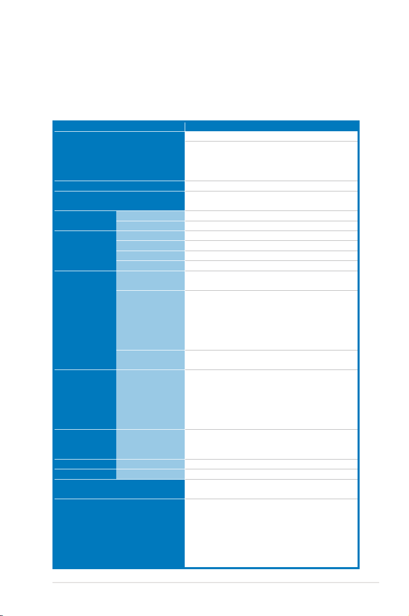
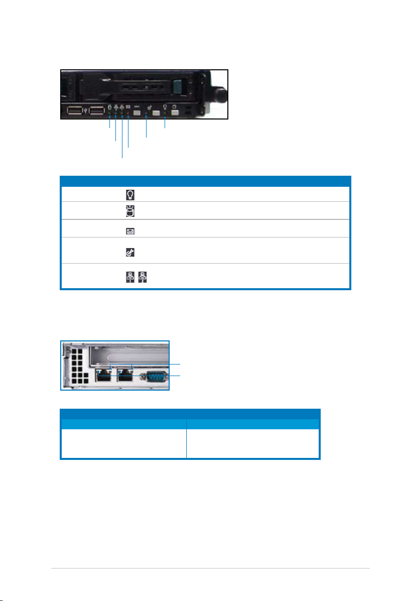
1.3 Front panel features
The barebone server displays a simple yet stylish front panel with easily accessible
features. The power and reset buttons, LED indicators, location switch, optical
drive, and two USB ports are located on the front panel.
Refer to section
Hot-swap HDD baysRack screw Rack screw
USB ports
HDD Access LED
LAN2 LED
LAN1 LED
Message LED
Reset button
Location LED
Location switch
1.6.2 Front panel LEDs
Power
button
Power LED
for the LED descriptions.
Optical drive
1.4 Rear panel features
The rear panel includes the expansion slots, system power socket, and rear fans.
The middle part includes the I/O shield with openings for the rear panel connectors
on the motherboard.
The ports for the PS/2 keyboard, PS/2 mouse, USB, VGA, and Gigabit LAN do
not appear on the rear panel if motherboard is not present.
LAN port2
Serial port
LAN port1
• Refer to section
Locator LED
Locator switch
Expansion slot
LAN port for iKVM
USB ports
1.6.1 Rear panel LEDs
PS/2 keyboard port
PS/2 mouse port
VGA port
Power fan
AC power socket
for the LED descriptions.
Power fan
• The LAN port for ASMB3 iKVM functions only when you install ASMB3
iKVM management card. Remove the mylar on the LAN port before using.
ASUS RS120-E5/PA2 1-5
Page 16
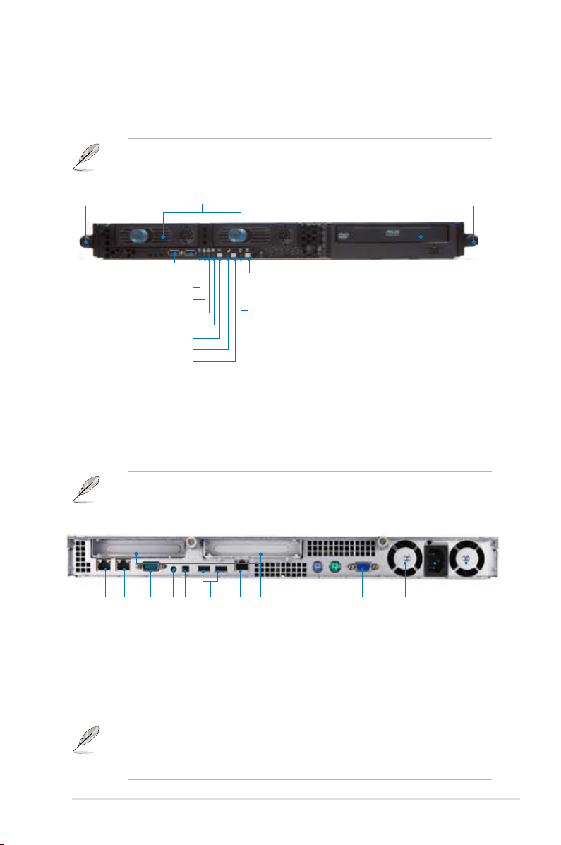
1.5 Internal features
The barebone server includes the basic components as shown.
2
1. PCI-E x8 and PCI-E x4 riser
card bracket
2. Power fans
1
4
3
3. ASUS P5BV-R motherboard
4. Power supply
5. Device fan (x 1)
6. System fans (x 3)
7. SATA backplane
6
8. Hot-swap HDD tray 1 -
5
Connects to SATA1 port
(Port0)
7
9. Hot-swap HDD tray 2 Connects to SATA2 port
(Port1)
10. Front I/O board (hidden)
8
9
10
• The barebone server does not include a oppy disk drive. Connect a USB
oppy disk drive to any of the USB ports on the front or rear panel if you
need to use a oppy disk.
• Only ASUS CD/DVD-ROMs t the optical drive bay.
11
11. Optical drive
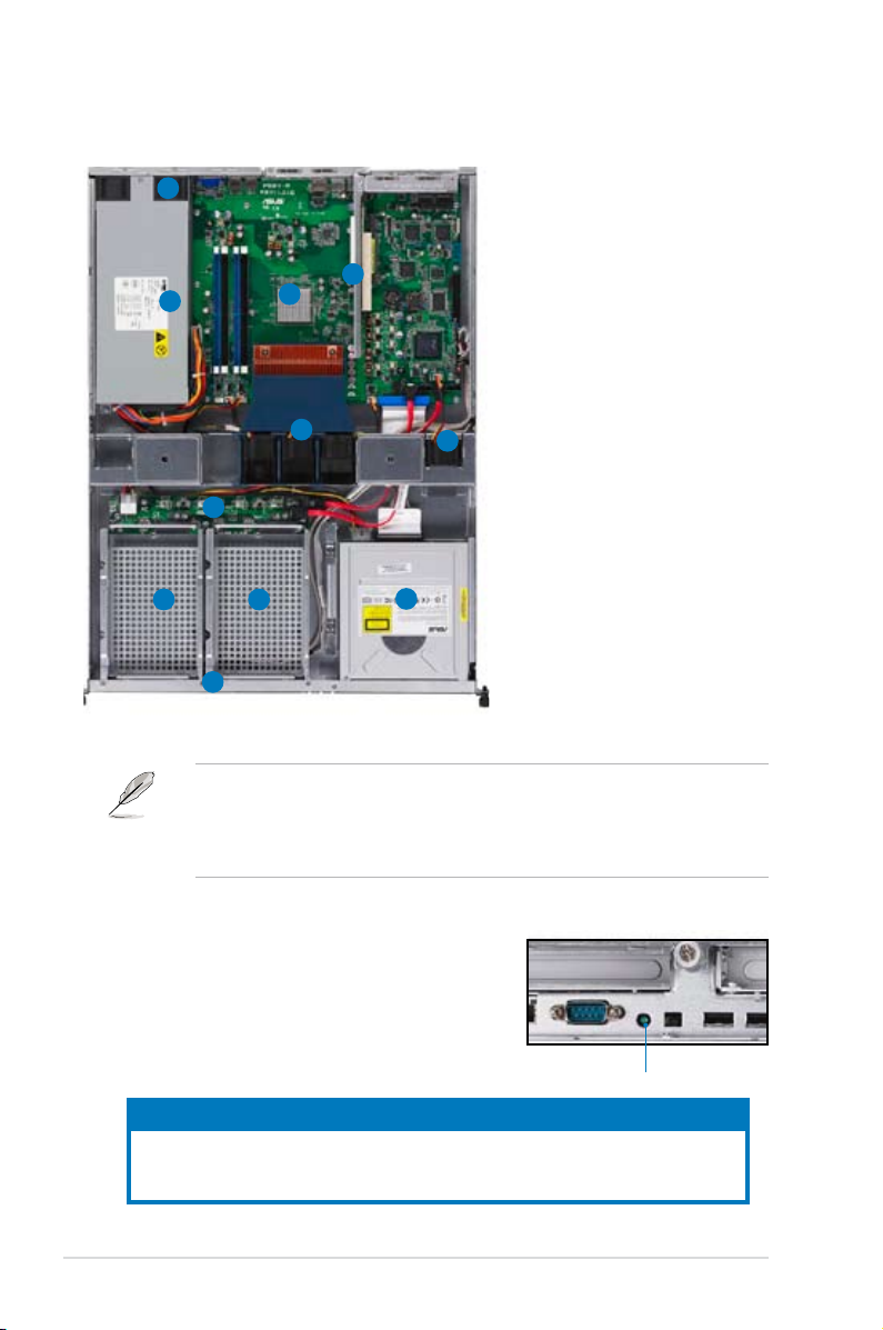
1.6 LED information
1.6.1 Rear panel LEDs
LED Display status Description
Location LED OFF Normal status
ON Location switch is pressed
(Press the location switch again to turn off)
Chapter 1: Product introduction1-6
Location LED
Page 17
1.6.2 Front panel LEDs
HDD Access LED
LAN2 LED
LAN1 LED
LED Icon Display status Description
Power LED ON
HDD Access LED
Message LED
Location LED
LAN LEDs
Message LED
Location LED
Power LED
OFF
Blinking
OFF
Blinking
OFF
ON
OFF
Blinking
ON
System power ON
No activity
Read/write data into the HDD
System is normal; no incoming event
ASWM indicates a HW monitor event
Normal status
Location switch is pressed
(Press the location switch again to turn off)
No LAN connection
LAN is transmitting or receiving data
LAN connection is present
1.6.3 LAN (RJ-45) LEDs
SPEED LED
ACT/LINK LED
ACT/LINK LED SPEED LED
Status Description Status Description
OFF No link OFF 10 Mbps connection
GREEN Linked ORANGE 100 Mbps connection
BLINKING Data activity GREEN 1 Gbps connection
ASUS RS120-E5/PA2 1-7
Page 18

Chapter 1: Product introduction1-8
Page 19

Chapter 2
This chapter lists the hardware setup
procedures that you have to perform
when in stalling or removing system
components.
ASUS RS120-E5/PA2
Hardware setup
2-
Page 20
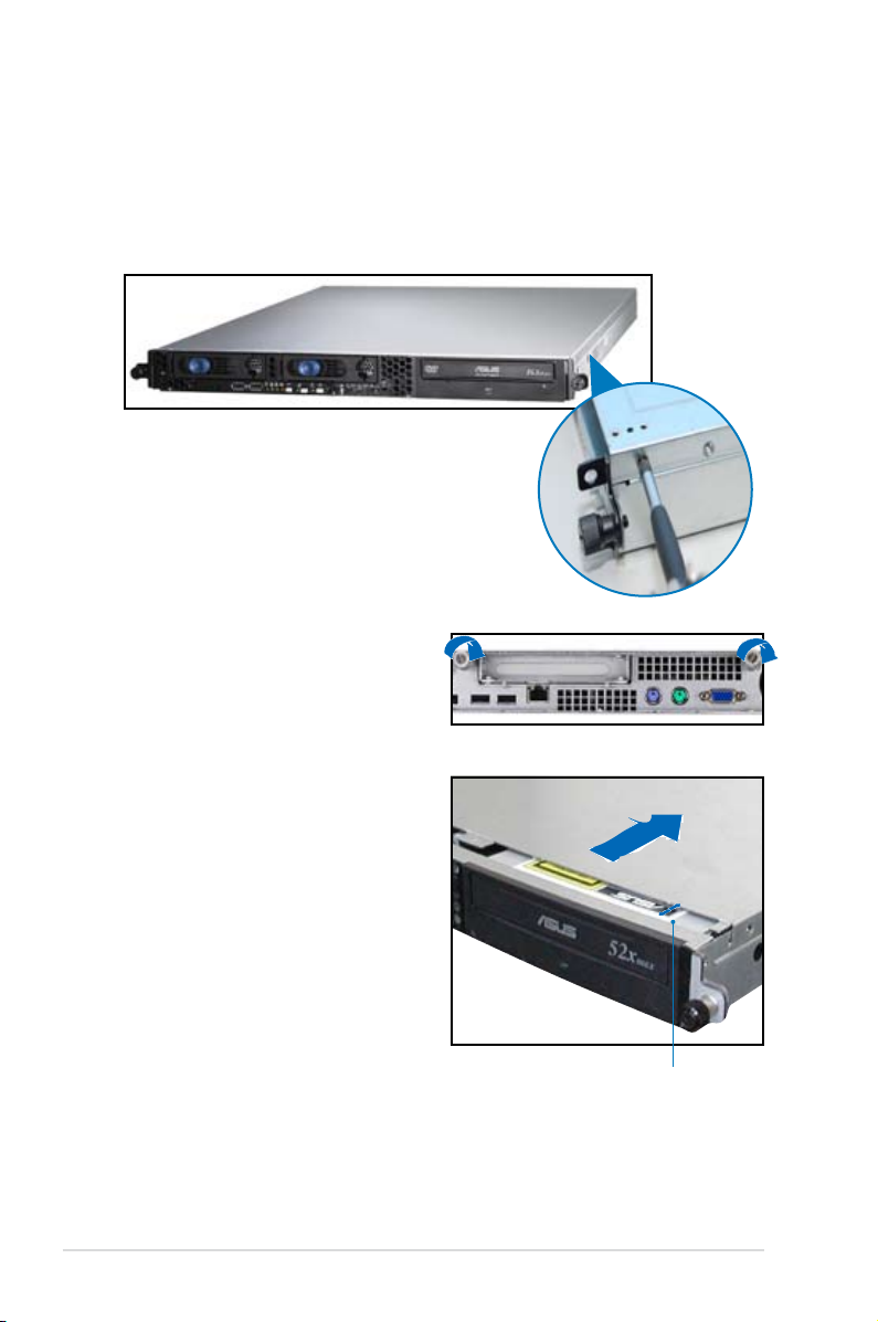
2.1 Chassis cover
2.1.1 Removing the cover
1. Use a Phillips screwdriver to remove the screw on each front end of the top
cover.
2. Loosen the two thunbscrews on the
rear panel to release the top cover
from the chassis.
3. Firmly hold the cover and slide it
toward the rear panel for about half
an inch until it is disengaged from
the chassis.
4. Lift the cover from the chassis.
1/2 inch distance
Chapter 2: Hardware setup2-2
Page 21
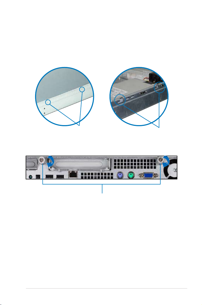
2.1.2 Installing the cover
1. Position the cover on top of the chassis with the thumbscrews on the rear,
and leave a gap of about half an inch from the front panel.
2. Make sure that the pegs on the cover (two on each side) are aligned to the
grooves on the chassis.
Pegs inside
3. Slide the cover toward the front until it snaps in place.
4. Tighten the thumbscrews on the rear to secure the cover.
Thumbscrews
Grooves
2-3ASUS RS120-E5/PA2
Page 22
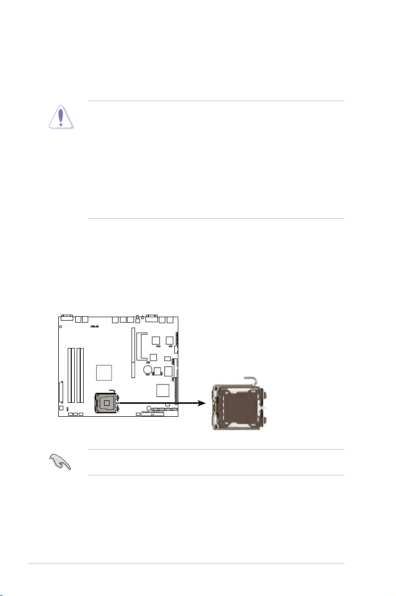
2.2 Central Processing Unit (CPU)
P5BV-R
®
P5BV-R CPU Socket 775
The system motherboard comes with a surface mount LGA775 socket designed
for Intel® Xeon 3000 series and Xeon X3200 series processor in the 775-land
package.
•
Upon purchase of the motherboard, make sure that the PnP cap is on
the socket and the socket contacts are not bent. Contact your retailer
immediately if the PnP cap is missing, or if you see any damage to the PnP
cap/socket contacts/motherboard components. ASUS will shoulder the cost
of repair only if the damage is shipment/transit-related.
•
Keep the cap after installing the motherboard. ASUS will process Return
Merchandise Authorization (RMA) requests only if the motherboard comes
with the cap on the CPU socket.
• The product warranty does not cover damage to the socket contacts
resulting from incorrect CPU installation/removal, or misplacement/loss/
incorrect removal of the PnP cap.
2.2.1 Installing the CPU
To install a CPU:
1. Locate the CPU socket on the motherboard.
Before installing the CPU, make sure that the cam box is facing towards you
and the load lever is on your left.
Chapter 2: Hardware setup2-4
Page 23
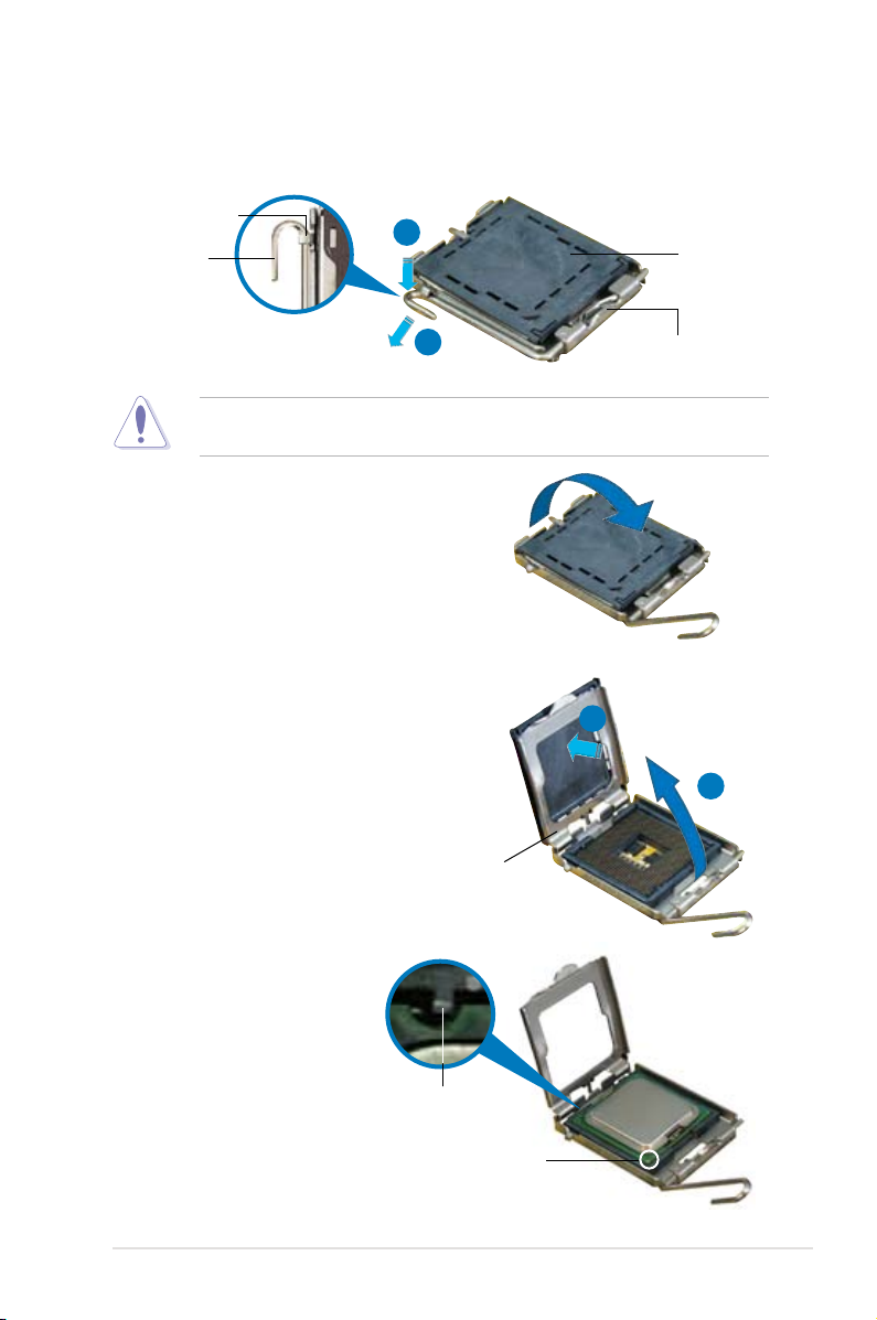
2. Press the load lever with your thumb (A), then move it to the left (B) until it is
released from the retention tab.
Retention tab
A
Load lever
B
To prevent damage to the socket pins, do not remove the PnP cap unless you
are installing a CPU.
3. Lift the load lever in the direction of
the arrow to a 135º angle.
4. Lift the load plate with your thumb
and forenger to a 100º angle (A),
then push the PnP cap from the load
plate window to remove (B).
PnP cap
This side of the socket
box should face you.
B
A
5. Position the CPU over
the socket, making sure
that the gold triangle is
on the bottom-left corner
of the socket. The socket
alignment key should t
into the CPU notch.
Load plate
Alignment key
Gold triangle mark
2-5ASUS RS120-E5/PA2
Page 24
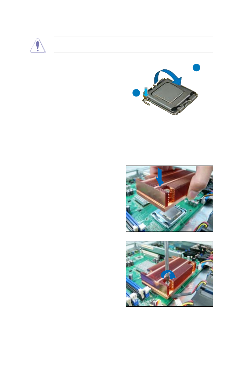
The CPU ts in only one correct orientation. DO NOT force the CPU into the
socket to prevent bending the connectors on the socket and damaging the CPU!
6. Close the load plate (A), then push
the load lever (B) until it snaps into
the retention tab.
B
2.2.2 Installing the CPU heatsink and airduct
To install the CPU heatsink:
1. Carefully place the heatsink on top
of the installed CPU.
2. Insert and loosely tighten each
screw in a diagonal sequence
rst. After all the screws have
been inserted, drive the screws to
completely secure the heatsink.
A
Chapter 2: Hardware setup2-6
Page 25
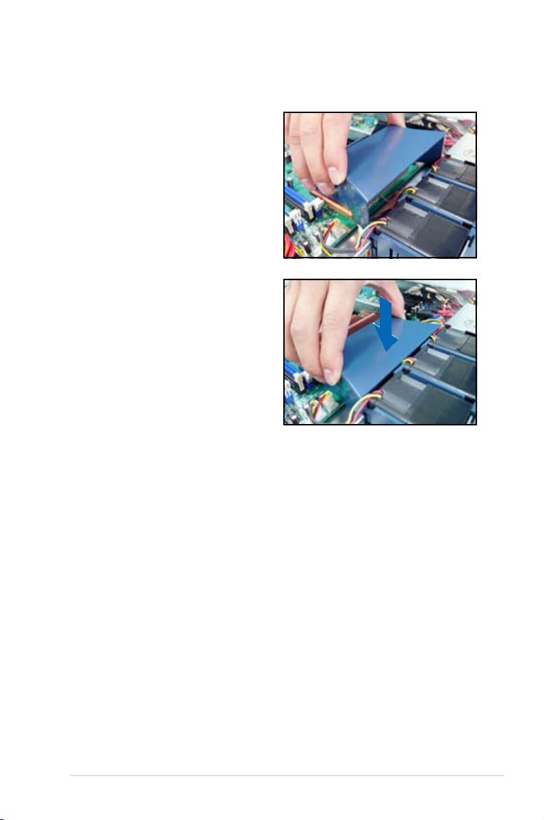
To install the airduct:
1. Position the airduct on top of the
heatsink.
2. Carefully lower the airduct until it ts
in place.
2-7ASUS RS120-E5/PA2
Page 26
2.3 System memory
P5BV-R
®
P5BV-R 240-pin DDR2 DIMM sockets
DIMM_A1
DIMM_B2
DIMM_B1
DIMM_A2
112 Pins 128 Pins
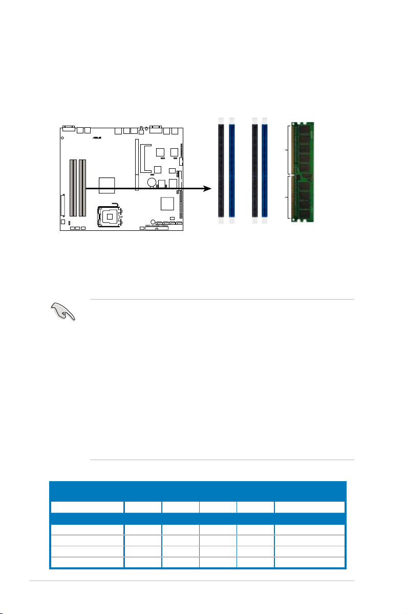
2.3.1 DIMM sockets location
The system motherboard comes with four Double Data Rate II (DDR2) Dual Inline
Memory Modules (DIMM) sockets to support 240-pin DDR2 modules.
The gure illustrates the location of the DDR2 DIMM sockets:
2.3.2 Memorycongurations
You may install 512 MB, 1 GB, and 2 GB unbuffered ECC or non-ECC
DDR2-667/800 DIMMs to the DIMM sockets.
• Always install DIMMs with the same CAS latency. For optimum
compatibility, we recommend you obtain memory modules from the same
vendor. Visit the ASUS website for an updated DDR2 Qualied Vendors List
for this motherboard.
• Due to chipset resource allocation, and depending on the number of
expansion cards installed, the following conditions may occur:
- the system may detect less than 8 GB system memory when
you installed four 2 GB DDR2 memory modules
- may show an available memory space of less than 4 GB when
you installed four 1 GB DDR2 memory modules
• Three DDR2 DIMMs installed into any three memory sockets will function in
Dual channel asymmetric mode.
• When installing a single or two DIMMs, install the modules on the blue slots
(DIMM_A1/DIMM_B1). Refer to the recommended memory conguration
table below.
Recommendedmemorycongurations
Mode Single channel mode Dual channel mode
Number of memories 1 1 2 4 3
DIMM socket
DIMM_A1 V V V V
DIMM_A2 V V
DIMM_B1 V V V V
DIMM_B2 V
Dual channel
(asymmetric mode)
Chapter 2: Hardware setup2-8
Page 27
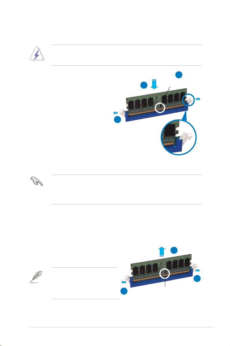
2.3.3 Installing a DIMM
Make sure to unplug the power supply before adding or removing DIMMs or
other system components. Failure to do so may cause severe damage to both
the motherboard and the components.
To install a DIMM:
1. Unlock a DIMM socket by
pressing the retaining clips
outward.
2. Align a DIMM on the socket
such that the notch on the
DIMM matches the break on the
socket.
3. Firmly insert the DIMM into the
socket until the retaining clips
snap back in place and the
DIMM is properly seated.
• A DDR2 DIMM is keyed with a notch so that it ts in only one direction. DO
NOT force a DIMM into a socket to avoid damaging the DIMM.
• The DDR2 DIMM sockets do not support DDR DIMMs. DO NOT install
DDR DIMMs to the DDR2 DIMM sockets.
2.3.4 Removing a DIMM
Follow these steps to remove a DIMM.
2
3
1
DDR2 DIMM notch
Unlocked retaining clip
1. Simultaneously press the retaining
clips outward to unlock the DIMM.
Support the DIMM lightly with
your ngers when pressing the
retaining clips. The DIMM might
get damaged when it ips out with
extra force.
2. Remove the DIMM from the socket.
2
1
1
DDR2 DIMM notch
2-9ASUS RS120-E5/PA2
Page 28
2.4 Hard disk drives
The system supports two hot-swap Serial ATA hard disk drives. The hard disk drive
installed on the left tray connects to the motherboard SATA1 (Port0) port, while the
right tray hard disk drive connects to the motherboard SATA3 (Port2) port via the
SATA backplane.
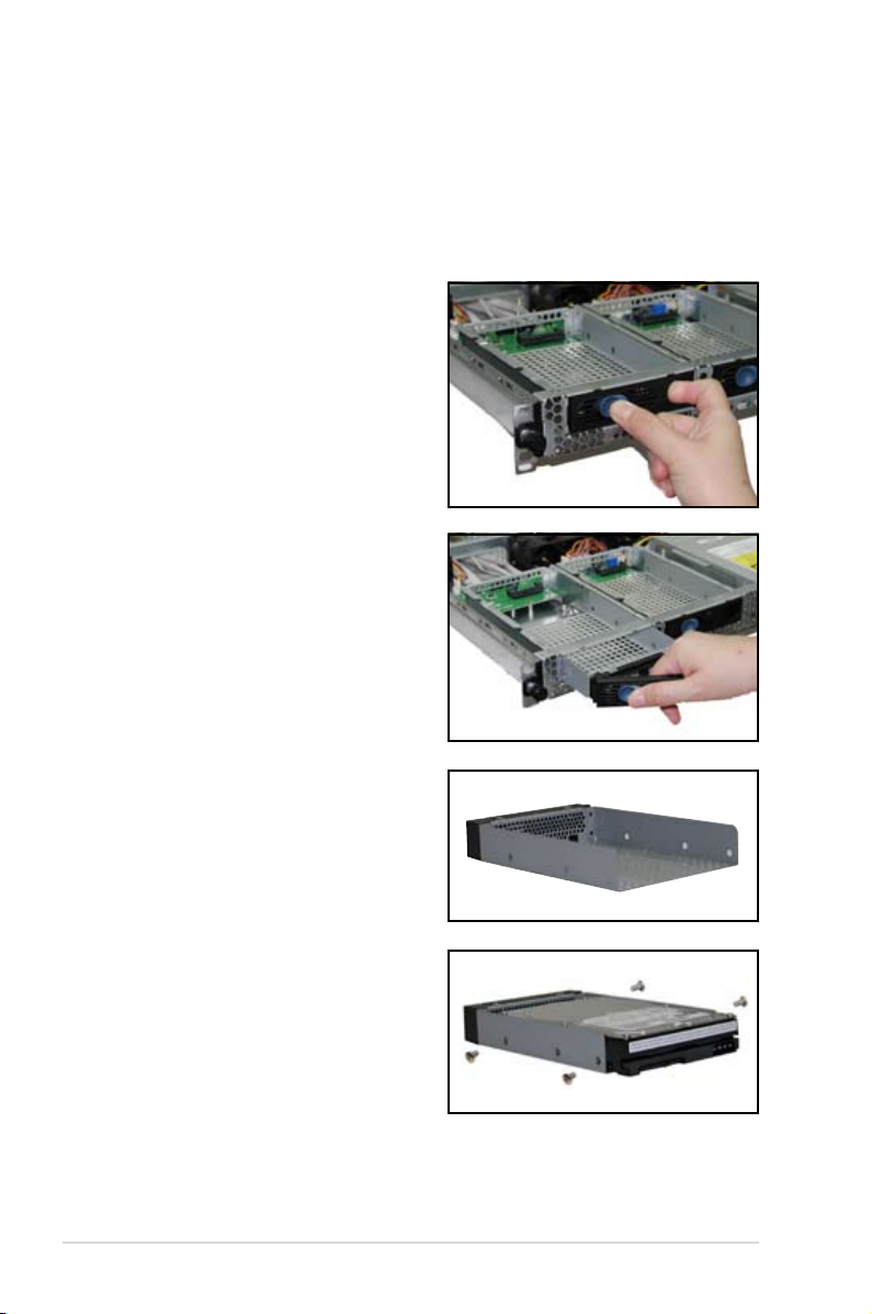
To install a hot-swap SATA HDD:
1. Release a drive tray by pushing the
spring lock to the right, then pulling
the tray lever outward. The drive
tray ejects slightly after you pull out
the lever.
2. Firmly hold the tray lever and pull
the drive tray out of the bay.
3. Take note of the drive tray holes.
Each side has three holes to t
different types of hard disk drives.
Use two screws on each side to
secure the hard disk drive.
4. Place a SATA hard disk drive on the
tray, then secure it with four screws.
Chapter 2: Hardware setup2-10
Page 29
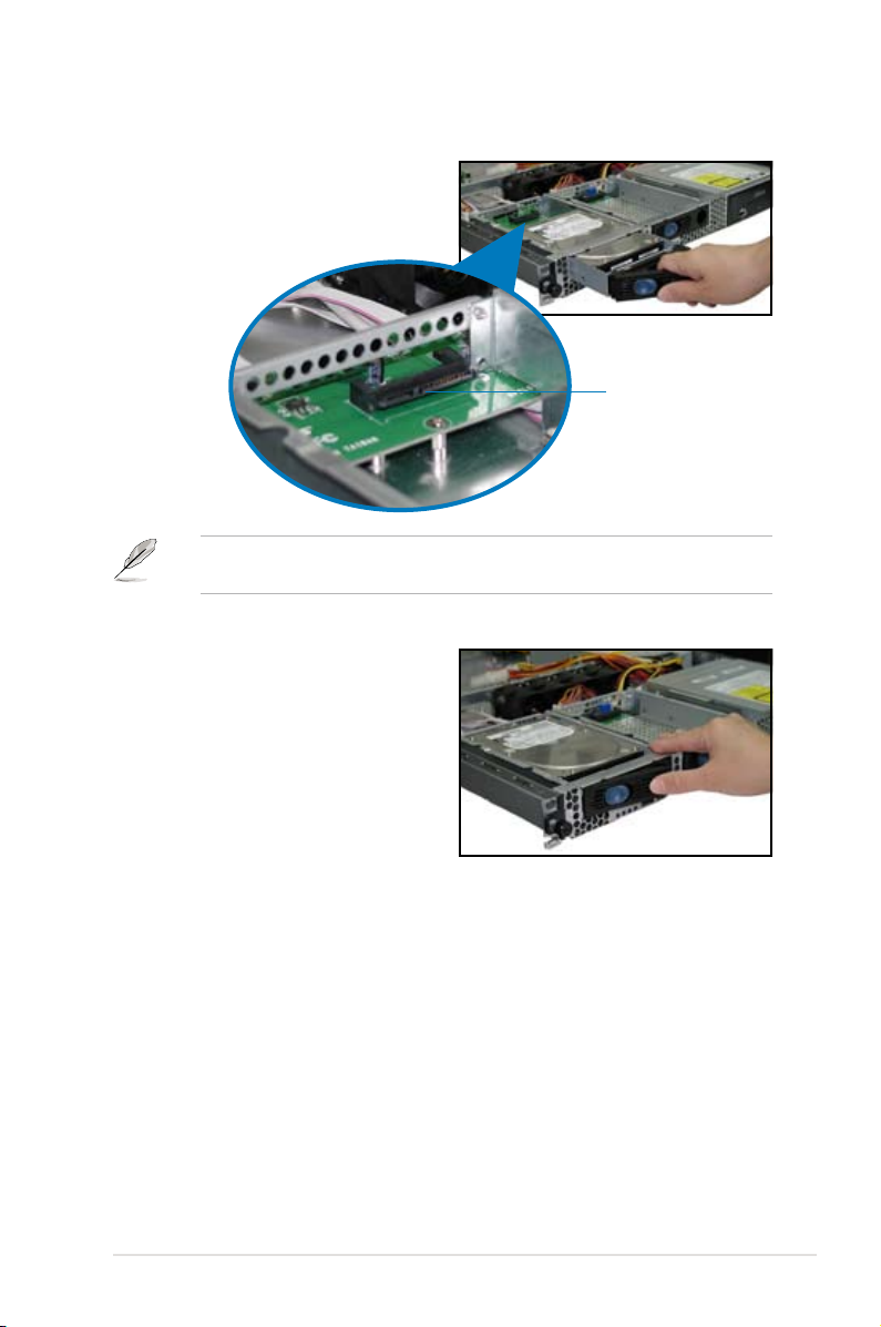
5. Carefully insert the drive tray and
push it all the way to the depth of
the bay until just a small fraction of
the tray edge protrudes.
When installed, the SATA connector on the drive connects to the SATA interface
on the backplane.
6. Push the tray lever until it clicks,
and secures the drive tray in place.
The drive tray is correctly placed
when its front edge aligns with the
bay edge.
7. Repeat steps 1 to 6 if you wish to
install a second SATA drive.
SATA interface
on the backplane
8. Connect the bundled SATA cables to the connectors on the SATA backplane.
Refer to section
2.7 SATA backplane cabling
for information on the SATA
backplane cable connections.
2-11ASUS RS120-E5/PA2
Page 30
2.5 Expansion slot
2.5.1 Installing an expansion card to the riser card bracket
The barebone server comes with a riser card bracket. You need to remove the
bracket if you want to install a PCIE X16 (x8 link) and/or a PCIE x8 (x4 link)
expansion cards.
To install a PCIE x8 card:
1. Firmly hold the riser card bracket,
then pull it up to detach it from
the PCI Express slot on the
motherboard.
2. Place the riser card bracket on
a at and stable surface, then
remove the screw from the PCIE x8
slot bay.
PCIE x8 slot
3. Install a PCIE x8 card to the
bracket as shown, then secure the
card with a screw.
Chapter 2: Hardware setup2-12
Page 31

To install a PCI Express x4 card:
1. Follow steps 1 to 2 of the previous
section.
PCI Express x4 slot
2. Use a Phillips (cross) screwdriver
to remove the screw that secures
the slot metal cover.
3. Remove the slot metal cover, then
set it aside.
4. Install a PCI Express x4 card to
the bracket as shown, then secure
the card with a screw you removed
earlier.
2-13ASUS RS120-E5/PA2
Page 32

2.5.2 Reinstalling the riser card bracket
To reinstall the riser card bracket:
1. Take note of the holes on the riser card bay. The four pegs on the riser card
bracket should match these holes to ensure that the bracket is properly in
place.
Pegs on the riser card
bracket
2. Install the riser card bracket with
the card into the PCI Express slot
on the motherboard.
3. Press the riser card bracket until
the golden connectors completely
t the slot and the bracket aligns
with the rear panel.
4. Connect the cable(s) to the card, if
applicable.
Chapter 2: Hardware setup2-14
Page 33

2.5.3 Replacing the optional riser card
The optional PCIX-E8-R10 riser card offers a better system expansion ability and
enables the system to install different add-in cards.
To replace the optional PCIX-E8-R10 riser card for RS120-E5:
1. Firmly hold the riser card bracket, then pull it up to detach it from the PCI
Express slot on the motherboard.
2. Unscrew the original riser card to remove it from the card bracket and set it
aside.
3. Align the screw holes on thePCIX-E8-R10 riser card with the ones on the
card bracket.
4. Fasten the riser card to the bracket with screws.
5. Follow the previous sections to install your expansion cards and reinstall the
card bracket back to the system.
2-15ASUS RS120-E5/PA2
Page 34

2.5.4 Conguringanexpansion card
After installing the expansion card, congure the it by adjusting the software
settings.
1. Turn on the system and change the necessary BIOS settings, if any. See
Chapter 5 for information on BIOS setup.
2. Assign an IRQ to the card. Refer to the following tables.
3. Install the software drivers for the expansion card.
Standard interrupt assignments
IRQ Priority Standard function
0 1 System Timer
1 2 Keyboard Controller
2 - Programmable Interrupt
3* 11 Communications Port (COM2)
4* 12 Communications Port (COM1)
5* 13 -6 14 Floppy Disk Controller
7* 15 -8 3 System CMOS/Real Time Clock
9* 4 ACPI Mode when used
10* 5 IRQ Holder for PCI Steering
11* 6 IRQ Holder for PCI Steering
12* 7 PS/2 Compatible Mouse Port
13 8 Numeric Data Processor
14* 9 Primary IDE Channel
15* 10 Secondary IDE Channel
*These IRQs are usually available for ISA or PCI devices.
PCI Bus Number, IDSEL, and IRQ assignments
PATA controller PIRQA#
SATA controller PIRQD#
SMBus controller PIRQB#
USB UHCI controller 1 PIRQH#
USB UHCI controller 2 PIRQD#
USB 2.0 EHCI controller PIRQH#
BCM5721 #1 PIRQA#
BCM5721 #2 PIRQB#
XG2 Z9s PIRQF#
PCI Express Slot 1 PIRQA#
PCI Express Slot 2 PIRQA#
INTA# INTB# INTC# INTD# REQ# GNT#
When using PCI cards on shared slots, ensure that the drivers support “Share
IRQ” or that the cards do not need IRQ assignments. Otherwise, conicts will
arise between the two PCI groups, making the system unstable and the card
inoperable.
Chapter 2: Hardware setup2-16
Page 35

2.6 Cable connections
1
2
10
3
7
8
9
10
6
4
5
Pre-connected system cables
1. 24-pin SSI power connector (from power supply to motherboard)
2. 4-pin SSI power connector (power supply to motherboard)
3. SATA backplane power connector (from power supply)
4. Primary IDE connector (from motherboard to optical drive)
5. Device fan connector (from motherboard CHASSIS_FAN3 to device fan)
6. SATA connectors (from motherboard to SATA backplane board)
7. Panel connector (from motherboard to front I/O board)
8. Auxiliary panel connector (from motherboard to front I/O board)
9. USB connector (from motherboard to front I/O board)
10. System fan connectors (from motherboard CPU_FAN1-3 to system fans)
2-17ASUS RS120-E5/PA2
Page 36

2.7 SATA backplane cabling
Connects a 8-pin plug from power supply
Connect the SATA HDDs
Connects the SATA cable from SATA3 (Port2) on the MB
Connects the SATA cable from
SATA1 (Port0) on the MB
Chapter 2: Hardware setup2-18
Page 37

2.8 Removable components
You may need to remove previously installed system components when installing
or removing system devices, or when you need to replace defective components.
This section tells how to remove the following components:
1. System fans
2. Device fan
3. Power supply module
4. Optical drive
5. Motherboard
2.8.1 System fans
The system comes with:
• three units 28 mm * 40 mm 15500 rpm fans
Refer to the illustration below for location of the system fans.
28 mm * 40 mm system fans
Incorrect installation of the system fan with dummy case may cause CPU
overheating and automatic system shutdown.
2-19ASUS RS120-E5/PA2
Page 38

To uninstall the system fans:
1. Disconnect a system fan cable
from the fan connector on the
motherboard.
2. Lift the fan, then set aside.
3. Repeat step 1 to 2 to uninstall the
other system fans.
To reinstall the system fan:
1. Insert the fan to the fan cage. The
airow directional arrow on the
fan side should point towards the
system rear panel.
2. Connect the system fan cable to the
fan connector on the motherboard.
Chapter 2: Hardware setup2-20
Page 39

2.8.2 System fan with dummy case
The system fan for the memory module(s) comes with a dummy case that allows it
to t in the fan cage.
To replace the system fan with dummy case:
1. Uninstall the fan following the instructions in the previous section.
2. Pull the dummy case to the direction of the arrow to disengage its pegs from
the system fan.
Peg
3. Replace the system fan.
To reinstall the system fan with the dummy case:
1. Insert the dummy case pegs to the system fan holes until it ts in place.
2. Reinstall the system fan by following the instructions in the previous section.
Peg
2-21ASUS RS120-E5/PA2
Page 40

2.8.3 Device fan
The system comes with one 28 mm * 40 mm (15500 rpm) device fan.
Refer to the illustration below for location of the device fans.
28 mm * 40 mm device fan
To uninstall the device fan:
1. Disconnect the device fan
cable from the connector on the
motherboard.
2. Lift the fan, then set aside.
To reinstall the device fan:
1. Insert the fan to the fan cage. The
airow directional arrow on the fan
side should point towards the rear
panel.
2. Connect the device fan cable to the
fan connector on the motherboard.
Chapter 2: Hardware setup2-22
Page 41

2.8.4 Power supply module
To uninstall the power supply module:
1. Disconnect all the power cables
connected to the motherboard and
other system devices.
2. Use a Phillips (cross) screwdriver
to remove the screws that secure
the front end of the power supply.
3. From the rear panel, remove two
screws that secure the power
supply from the chassis.
4. Slide the power supply forward for
about half an inch, then carefully lift
it out from the chassis.
2-23ASUS RS120-E5/PA2
Page 42

2.8.5 Optical drive
To uninstall the optical drive:
1. Disconnect the power and signal
cables connected to the rear of
the optical drive.
3. Pull out half of the drive tray to
remove the tray bezel.
2. Insert the optical drive emergency
eject pin to the emergency eject
pin hole until the drive tray ejects.
4. Pull the center of the bezel
outward (A), then lift the sides (B)
to remove.
DO NOT apply too much force when removing the bezel. Too much force may
break the drive tray!
5. Replace the drive tray.
Chapter 2: Hardware setup2-24
Page 43

6. Remove two metal bracket screws and screws on the other side of the drive.
Keep the screws for later use.
7. Pull the metal bracket to the
direction of the arrow until its pegs
disengage from the drive holes.
8. Lift the metal bracket, then set
aside.
9. Push the drive inward, then lift it
out from the chassis.
10. Remove the metal rail on the
other side of the drive.
2-25ASUS RS120-E5/PA2
Page 44

To reinstall the optical drive, follow the instructions in the previous chapter in a
P5BV-R
®
reverse order.
When installing a new optical drive, make sure to remove the drive front panel
assembly and tray bezel before installing it to the chassis.
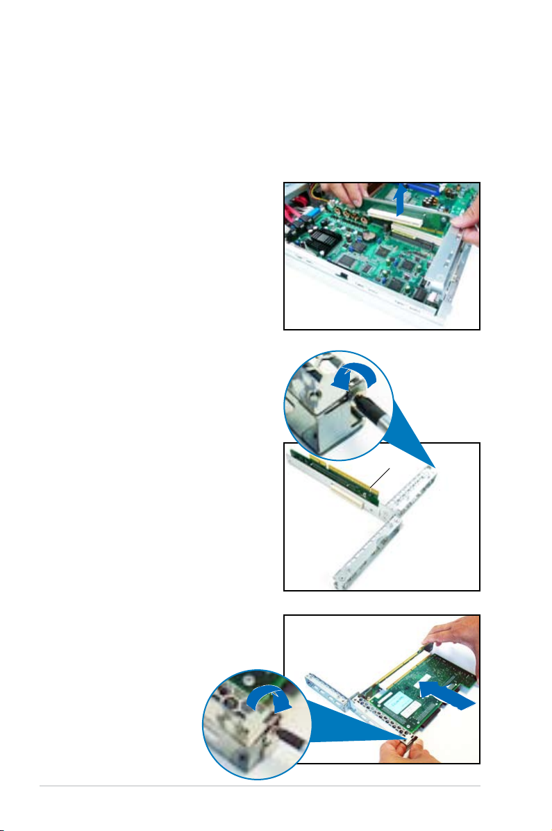
2.8.6 Motherboard
To uninstall the motherboard:
1. Disconnect all the pre-connected cables from the motherboard.
See section
2.6 Cable connections
for details.
2. Uninstall all the devices from the motherboard including the CPU and
heatsink, riser card bracket, and DDR2 DIMMs. Refer to the corresponding
sections for instructions on removing these components.
3. Use a Philips (cross) screwdriver to remove the screws that secure the
motherboard to the base of the chassis.
Refer to the illustration below for the location of the motherboard screws.
4. Carefully lift the motherboard out of
the chassis as shown.
Chapter 2: Hardware setup2-26
Page 45

To reinstall the motherboard:
1. Firmly hold the motherboard by the
sides and insert it into the chassis
as shown.
2. Carefully adjust the motherboard
until the rear panel ports t in place.
3. Use a Phillips (cross) screwdriver to
secure the motherboard with ten (10)
screws in the holes as shown in the
illustration in the previous section.
4. Reconnect all the required cables
to the motherboard. See section
Cable connections
for details.
2.6
5. Reinstall all the devices that you
have previously removed.
2-27ASUS RS120-E5/PA2
Page 46

Chapter 2: Hardware setup2-28
Page 47

Chapter 3
This chapter describes how to install
the optional components and devices
into the barebone server.
ASUS RS120-E5/PA2
Installation options
2-
Page 48

3.1 Rackmount rail kit items
If you have the rackmount rail kit, it contains two pairs of rails (one pair for each
side of the barebone system), and eight (8) pairs of nut-and-bolt type screws.
Nuts
Bolts
Left pair
Right pair
3.2 Rack rails assembly
To assemble the rack rails:
1. Determine the depth of the rack where you wish to install the system.
2. Match one long and one short rail to your desired length, and x them
together using four (4) pairs of nuts and bolts.
3. Repeat step 2 to assemble the other rail pair.
Rear ends
Bolts on inner side
Nuts on outer side
Front ends
Chapter 3: Installation options3-2
Page 49

3.3 Attaching the rails to the rack
To attach the rails to the rack:
1. Select one unit of space (1U) on the rack
where you wish to install the barebone
server.
2. Remove the screws from the 1U space on
the rack front.
3. Align the front end holes of a rack rail pair
to the 1U space.
4. Drive in two screws on the outer holes to
secure the front end.
1U space
5. Find the rear 1U space that corresponds to the front 1U space where you
attached the rail.
6. Remove the screws from the rear 1U space, and align the rear end holes.
7. Drive in two screws on the outer holes to secure the rear end.
8. From the rack front, nd the corresponding 1U space for the second rail pair.
9. Repeat steps 2 to 7 to attach the second rail pair. When properly installed,
the rack rails appear as shown.
3-3ASUS RS120-E5/PA2
Page 50

3.4 Rackmounting the server
To mount the server to the rack:
1. Firmly hold the server on both sides and insert the rear panel side to the front
end of the rack rail, then carefully push the server all the way to the back until
the front panel ts the front end of the rack, and the rack screws on the server
match the middle hole on the rack..
2. Tighten the two rack screws to
secure the server to the rack.
Rack screw
Chapter 3: Installation options3-4
Page 51

Chapter 4
This chapter includes the motherboard
layout, and brief descriptions of the
jumpers and internal connectors.
ASUS RS120-E5/PA2
Motherboard info
Page 52

4.1 Motherboard layout
P5BV-R
8Mbi
t
Flash
BIO
S
Super
I/O
31cm (12.2in)
26cm (10.2in)
CR203
2 3V
Lithium
Cell
CMOS
Powe
r
®
ATX12V1
CLRTC1
L2_EN
Intel
®
3200
Intel
®
ICH7R
RISER_PCE1
BMCSOCKET1
DDR2 DIMM_A1 (64 bit,240-pin module)
DDR2 DIMM_B1 (64 bit,240-pin module)
DDR2 DIMM_A2 (64 bit,240-pin module)
DDR2 DIMM_B2 (64 bit,240-pin module)
LGA775
ATXPWR1
SATA4
Broadcom
BCM5721
Broadcom
BCM5721
LAN1
VGA_EN1
RECOVERY1
COM2
FLOPPY1
HDLED1
RAID_SEL1
USB34
BPSMB1
PANEL1
AUX_PANEL1
USB2 USB1
PS2_MS1 PS2_KB1
VGA1
COM1
LOCSW1
LOCLED1
SB_PWR1
PRI_IDE1
LAN2LAN3
L1_EN
CPU_FAN4 CPU_FAN2
CPU_FAN3
CPUFAN_SEL1
CPU_FAN1
RISER_PCE2
CHASS_FAN1
SATA3SATA2SATA1
BUZZ1
LPC1
XGI
Volari
32MB DDR2
(VGA)
Z9s
Chapter 4: Motherboard information4-2
Page 53

Layout contents
Jumpers Page
1. Clear RTC RAM (CLRTC1) 4-4
2. Gigabit LAN1 controller setting (3-pin LAN_EN1)
3. Gigabit LAN2 controller setting (3-pin LAN_EN2)
4. Integrated graphics controller (3-pin VGA_EN1)
5. RAID controller selection (3-pin RAID_SEL1)
6. Force BIOS recovery (3-pin RECOVERY1)
Internal connectors Page
1. Floppy disk drive connector (34-1 pin FLOPPY1) 4-8
connector (40-1 pin PRI_IDE1) 4-8
2. IDE
3. Serial ATA connectors (7-pin SATA1, SATA2, SATA3,
SATA4)
4. Hard disk activity LED connector (4-pin HDLED1)
5. System and device fan connectors (3-pin CPU_FAN1/2/3/4;
CHASSIS_FAN1)
6. USB port connector (10-1 pin USB34)
7. Serial port connector (10-1 pin COM2)
8. SSI power
9. LPC debug card
10. Backplane SMBus
12. Auxiliary panel connector (20-pin AUX_PANEL1)
13. System panel
connectors (24-pin ATXPWR1, 4-pin ATX12V1) 4-12
connector (14-1 -pin LPC1) 4-13
connector (6-1 pin BPSMB1) 4-13
connector (20-pin PANEL1) 4-15
4-5
4-5
4-6
4-6
4-7
4-9
4-10
4-10
4-11
4-11
4-14
ASUS RS120-E5/PA2 4-3
Page 54

4.2 Jumpers
P5BV-R
®
P5BV-R Clear RTC RAM
CLRTC1
Normal
(Default)
Clear CMOS
2
1
2
3
1. Clear RTC RAM (CLRTC1)
This jumper allows you to clear the Real Time Clock (RTC) RAM in CMOS.
You can clear the CMOS memory of date, time, and system setup parameters
by erasing the CMOS RTC RAM data. The onboard button cell battery
powers the RAM data in CMOS, which includes system setup information
such as system passwords.
To erase the RTC RAM:
1. Turn OFF the computer and unplug the power cord.
2. Move the jumper cap from pins 1-2 (default) to pins 2-3. Keep the cap on
pins 2-3 for about 5~10 seconds, then move the cap back to pins 1-2.
3. Plug the power cord and turn ON the computer.
4. Hold down the <Del> key during the boot process and enter BIOS setup
to re-enter data.
Except when clearing the RTC RAM, never remove the cap on CLRTC jumper
default position. Removing the cap will cause system boot failure!
If the steps above do not help, remove the onboard battery and move the
jumper again to clear the CMOS RTC RAM data. After the CMOS clearance,
reinstall the battery.
Chapter 4: Motherboard information4-4
Page 55

2. Gigabit LAN1 controller setting (3-pin L1_EN)
P5BV-R
®
P5BV-R Gigabit LAN1 setting
L1_EN
Enable
(Default)
Disable
2 13 2
P5BV-R
®
P5BV-R Gigabit LAN2 setting
L2_EN
Enable
(Default)
Disable
2 13 2
This jumper allows you to enable or disable the Broadcom
®
Gigabit LAN
controller that controls the LAN1 port. Place a jumper cap on pins 1-2 to
activate the Gigabit LAN1 controller.
3. Gigabit LAN2 controller setting (3-pin L2_EN)
This jumper allows you to enable or disable the Broadcom
controller that controls the LAN2 port. Place a jumper cap on pins 1-2 to
activate the Gigabit LAN2 controller.
®
Gigabit LAN
ASUS RS120-E5/PA2 4-5
Page 56

4. Integrated graphics controller (3-pin VGA_EN1)
P5BV-R
®
P5BV-R RAID select jumper
RAID_SEL1
LSI RAID ROM
(Default)
INTEL RAID ROM
2
1
2
3
P5BV-R
®
P5BV-R VGA setting
VGA_EN1
Enable
(Default)
Disable
2 13 2
This jumper allows you to enable or disable the onboard graphics controller.
5. RAID controller selection (3-pin RAID_SEL1)
This jumper allows you to select the RAID conguration utility to use when
you create disk arrays. Place the jumper cap over pins 1-2 if you want to use
the LSI Logic Embedded SATA RAID Utility (default); otherwise, place the
jumper cap to pins 2-3 to use the Intel® Matrix Storage Manager utility.
Chapter 4: Motherboard information4-6
Page 57

6. Force BIOS recovery (3-pin RECOVERY1)
P5BV-R
®
P5BV-R BIOS recovery setting
RECOVERY1
(Default)
Normal BIOS recovery
2
1
2
3
This jumper allows you to update or recover the BIOS settings when it gets
corrupted or destroyed. This jumper allows you to update/recover the BIOS
quickly.
To update the BIOS:
1. Prepare a CD-ROM that contains the original or latest BIOS for the
motherboard (P5BV-R.ROM) and the AFUDOS.EXE utility.
2. Set the jumper to pins 2-3.
3. Restart the system, then insert the CD-ROM to the optical drive to
recover or update the BIOS.
4. Shut down the system.
5. Set the jumper back to pins 1-2.
6. Turn on the system.
ASUS RS120-E5/PA2 4-7
Page 58

4.3 Connectors
P5BV-R
®
NOTE: Orient the red markings on
the floppy ribbon cable to PIN 1.
P5BV-R Floppy disk drive connector
FLOPPY1
PIN 1
P5BV-R
®
P5BV-R IDE connector
NOTE: Orient the red markings
(usually zigzag) on the IDE
ribbon cable to PIN 1.
PRI_IDE1
1. Floppy disk drive connector (34-1 pin FLOPPY1)
This connector is for the provided oppy disk drive (FDD) signal cable. Insert
one end of the cable to this connector, then connect the other end to the
signal connector at the back of the oppy disk drive.
Pin 5 on the connector is removed to prevent incorrect cable connection when
using a FDD cable with a covered Pin 5.
2. IDE connector (40-1 pin PRI_IDE1)
This connector is for an Ultra ATA 100/66/33 signal cable. By default, this
connector supports the optical disk drive. You must congure the optical drive
as master/slave device by setting its jumper accordingly. Refer to the optical
disk drive documentation for the jumper settings.
Pin 20 on the IDE connectors is removed to match the covered hole on the Ultra
ATA cable connector. This prevents incorrect insertion when you connect the
IDE cable.
Chapter 4: Motherboard information4-8
Page 59

3. Serial ATA connectors (7-pin SATA1, SATA2, SATA3, SATA4)
P5BV-R
®
P5BV-R SATA connectors
SATA1
GND
RSATA_TXP1
RSATA_TXN1
GND
RSATA_RXN1
RSATA_RXP1
GND
SATA2
GND
RSATA_TXP2
RSATA_TXN2
GND
RSATA_RXN2
RSATA_RXP2
GND
SATA3
GND
RSATA_TXP3
RSATA_TXN3
GND
RSATA_RXN3
RSATA_RXP3
GND
SATA4
GND
RSATA_TXP4
RSATA_TXN4
GND
RSATA_RXN4
RSATA_RXP4
GND
These connectors are for the Serial ATA signal cables for Serial ATA hard disk
drives.
If you installed Serial ATA hard disk drives, you can create a RAID 0 and
RAID 1, RAID 5 and RAID10 conguration using the Intel® Matrix Storage
Manager, or RAID 0, RAID 1, and RAID 10 conguration using the LSI Logic
Embedded SATA RAID utility in the Intel® ICH7R Southbridge.
These connectors are set to IDE mode by default. In IDE mode, you can connect Serial
ATA boot/data hard disk drives to these connectors. If you intend to create a Serial ATA
RAID set using these connectors, set the
See section 5.3.4 for details.
CongureSATAAs
item in the BIOS to [RAID].
Serial ATA hard disk drive connection
Connector Setting
SATA1/SATA2 Master
SATA3/SATA4 Slave
ASUS RS120-E5/PA2 4-9
When using the connectors in IDE mode, connect the primary (boot) hard
disk drive to the SATA1 or SATA2 connector. Refer to the table below for the
recommended SATA hard disk drive connections.
Page 60

4. Hard disk activity LED connector (4-pin HDLED1)
P5BV-R
®
PIN 1
ADD_IN_CARD_ACT#
+5V
ADD_IN_CARD_ACT#
+5V
P5BV-R Hard disk activity LED connector
HDLED1
P5BV-R
®
P5BV-R Fan connectors
CPU_FAN4
GND
CPU FAN PWR
CPU FAN IN
CPU FAN PWM
CPU_FAN3
GND
CPU FAN PWR
CPU FAN IN
CPU FAN PWM
CPU_FAN2
GND
CPU FAN PWR
CPU FAN IN
CPU FAN PWM
CHASS_FAN1
GND
CPU FAN PWR
CPU FAN IN
CPU FAN PWM
CPU_FAN1
GND
CPU FAN PWR
CPU FAN IN
CPU FAN PWM
CHASS_FAN1
CPU_FAN2
CPU_FAN1
CPU_FAN3
CPU_FAN4
For some storage cards, such as SCSI card, with access signals for external
LEDs, this connector allows the access signals to go through the front panel
IDE_LED lead.
5. System and device fan connectors (3-pin CPU_FAN1/2/3/4;
CHASSIS_FAN1)
The fan connectors support the system and device fans.
These are not jumpers! DO NOT place jumper caps on the fan connectors!
Chapter 4: Motherboard information4-10
Page 61

6. USB port connector (10-1 pin USB34)
P5BV-R
®
P5BV-R
Serial port2 (COM2) connector
PIN 1
COM2
P5BV-R
®
P5BV-R USB 2.0 connectors
USB+5V
PIN1
USB_P3-
USB_P3+
GND
USB+5V
USB_P4-
USB _P4+
GND
NC
USB34
By default this connects to the front panel to support two USB 2.0 ports.
7. Serial port connector (10-1 pin COM2)
This connector is for a serial (COM) port. Connect the serial port module
cable to this connector, then install the module to a slot opening at the back
of the system chassis.
The serial port module is purchased separately.
ASUS RS120-E5/PA2 4-11
Page 62

8. SSI power connectors (24-pin ATXPWR1, 4-pin ATX12V1)
P5BV-R
®
P5BV-R ATX power connectors
24-pin
Power Connector
ATX12V1
ATXPWR1
+3 Volts
+3 Volts
Ground
+5 Volts
+5 Volts
Ground
Ground
Power OK
+5V Standby
+12 Volts
-5 Volts
+5 Volts
+3 Volts
-12 Volts
Ground
Ground
Ground
PSON#
Ground
+5 Volts
+12 Volts
+3 Volts
+5 Volts
1
Ground
GND +12V DC
GND +12V DC
These connectors are for SSI power supply plugs. The power supply plugs
are designed to t these connectors in only one orientation. Find the proper
orientation and push down rmly until the connectors completely t.
• Use of an SSI 12 V Specication 2.0-compliant power supply unit (PSU)
that provides a minimum power of 400 W is recommended for a fully-
congured system.
• DO NOT forget to connect the 4-pin ATX +12 V power plug; otherwise, the
system will not boot up.
• Use of a PSU with a higher power output is recommended when conguring
a system with more power consuming devices. The system may become
unstable or may not boot up if the power is inadequate.
• You must install a PSU with a higher power rating if you intend to install
additional devices.
Chapter 4: Motherboard information4-12
Page 63

9. LPC debug card connector (14-1 pin LPC1)
P5BV-R
®
+3.3V
PIN1
+3.3V +3.3V
GND GND
LPC_LAD2 LPC_LAD3
LPC_LAD0 LPC_LAD1
PLTRST LFRAME_N
CLK GND
P5BV-R LPC debug card connector
LPC1
P5BV-R
®
12CDAT P2
GND
FAN_PWM
+5V
I2CCLK P2
FAN_DC1
P5BV-R SMBus connector
BPSMB1
PIN 1
This is a low pin count interface used to plug in the LPC debug card.
10. Backplane SMBus connector (6-1 pin BPSMB1)
This connector allows you to connect SMBus (System Management Bus)
devices. Devices communicate with an SMBus host and other SMBus
devices using the SMBus interface.
ASUS RS120-E5/PA2 4-13
Page 64

11. Auxiliary panel connector (20-pin AUX_PANEL1)
P5BV-R
®
P5BV-R Auxiliary panel connector
AUX_PANEL1
I2C_4_DATA#LOCATORLED1+
+5VSBLOCATORLED1LAN1_LINKACTLED-LOCATORBTN#
LAN1_LINKACTLED+GND
+5VSB
I2C_4_CLK#
GNDGND
LAN2_LINKACTLED+LOCATORLED2LAN2_LINKACTLED-LOCATORLED2+
CASEOPEN
PIN 1
NC
This connector is for additional front panel features including front panel SMB,
locator LED and switch, chassis intrusion, and LAN LEDs.
• Front panel SMB (6-1 pin FPSMB)
These leads connect the front panel SMBus cable.
• LAN activity LED (2-pin LAN1_LED, LAN2_LED)
These leads are for Gigabit LAN activity LEDs on the front panel.
• Chassis intrusion (2-pin CHASSIS)
These leads are for the intrusion detection feature for chassis with
intrusion sensor or microswitch. When you remove any chassis
component, the sensor triggers and sends a high-level signal to these
leads to record a chassis intrusion event.
• Locator LED (6-pin LOCATOR)
These leads are for the locator switch and LED on the front panel.
Chassis intrusion
Locator LED and
switch
Front panel SMB
LAN activity LED
By default, a cable plug (6x2, 12-pin) connects the AUX_PANEL1 to the front
panel I/O board. The Pin1 on the cable plug is located at the top right corner
and is marked by a triangle. Take note of the Pin1 when reconnecting the cable
plug to prevent incorrect insertion.
Chapter 4: Motherboard information4-14
Page 65

12. System panel connector (20-pin PANEL1)
P5BV-R
®
P5BV-R System panel connector
PANEL1
MLED-GND
NCPOWERBTN#
+5VGND
GNDNC
POWERLED+HDLED+
GNDHDLEDPOWERLEDMLED+
GNDRESETBTN#
SPKROUTGND
PIN 1
This connector supports several chassis-mounted functions.
HDD LED
Power LED
Message LED
System warning
speaker
The sytem panel connector is color-coded for easy connection. Refer to the
connector descriptions below for details.
• System power LED (Green 3-pin PLED)
This 3-pin connector is for the system power LED. Connect the chassis power
LED cable to this connector. The system power LED lights up when you turn
on the system power, and blinks when the system is in sleep mode.
• Message LED (Brown 2-pin MLED)
This connector is for the message LED cable that connects to the front panel
message LED. The message LED indicates the booting status. The LED
blinks when the system is in the boot process until the operating system is
loaded.
• System warning speaker (Orange 4-pin SPEAKER)
This 4-pin connector is for the chassis-mounted system warning speaker. The
speaker allows you to hear system beeps and warnings.
• Hard disk drive activity LED (Red 2-pin HDD LED)
This 2-pin connector is for the HDD Activity LED. Connect the HDD Activity
LED cable to this connector. The IDE LED lights up or ashes when data is
read from or written to the HDD.
• ATX power button/soft-off button (Yellow 2-pin PWRSW)
This connector is for the system power button. Pressing the power button
turns the system on or puts the system in sleep or soft-off mode depending
on the BIOS settings. Pressing the power switch for more than four seconds
while the system is ON turns the system OFF.
• Reset button (Blue 2-pin RESET)
This 2-pin connector is for the chassis-mounted reset button for system
reboot without turning off the system power.
ASUS RS120-E5/PA2 4-15
Power button
Reset button
Page 66

Chapter 4: Motherboard information4-16
Page 67

Chapter 5
This chapter tells how to change the
system settings through the BIOS Setup
menus. Detailed descriptions of the BIOS
parameters are also provided.
ASUS RS120-E5/PA2
BIOS setup
Page 68

5.1 Managing and updating your BIOS
The following utilities allow you to manage and update the motherboard Basic
Input/Output System (BIOS) setup.
1.
ASUS AFUDOS
disk.)
2.
ASUS CrashFree BIOS 3
the motherboard support CD when the BIOS le fails or gets corrupted.)
Save a copy of the original motherboard BIOS le to a bootable oppy disk in
case you need to restore the BIOS in the future. Copy the original motherboard
BIOS using the ASUS Update or AFUDOS utilities.
(Updates the BIOS in DOS mode using a bootable oppy
(Updates the BIOS using a bootable oppy disk or
5.1.1 Creatingabootableoppydisk
1. Do either one of the following to create a bootable oppy disk.
DOS environment
a. Insert a 1.44MB oppy disk into the drive.
b. At the DOS prompt, type
format A:/S
Windows® XP environment
a. Insert a 1.44 MB oppy disk to the oppy disk drive.
b. Click
c. Select the 3 1/2 Floppy Drive icon.
d. Click
window appears.
e. Select
click
from the Windows® desktop, then select
Start
from the menu, then select
File
Create an MS-DOS startup disk
.
Start
then press <Enter>.
My Computer
. A
Format
Format 3 1/2 Floppy Disk
from the format options eld, then
.
2. Copy the original or the latest motherboard BIOS le to the bootable oppy
disk.
5-2 Chapter 5: BIOS setup
Page 69

5.1.2 AFUDOS utility
The AFUDOS utility allows you to update the BIOS le in DOS environment using
a bootable oppy disk with the updated BIOS le. This utility also allows you to
copy the current BIOS le that you can use as backup when the BIOS fails or gets
corrupted during the updating process.
Copying the current BIOS
To copy the current BIOS le using the AFUDOS utility:
• Make sure that the oppy disk is not write-protected and has at least 1024
KB free space to save the le.
• The succeeding BIOS screens are for reference only. The actual BIOS
screen displays may not be the same as shown.
1. Copy the AFUDOS utility (afudos.exe) from the motherboard support CD to
the bootable oppy disk you created earlier.
2. Boot the system in DOS mode, then at the prompt type:
afudos /o[lename]
where the [lename] is any user-assigned lename not more than eight
alphanumeric characters for the main lename and three alphanumeric
characters for the extension name.
A:\>afudos /oOLDBIOS1.rom
Main lename Extension name
3. Press <Enter>. The utility copies the current BIOS le to the oppy disk.
A:\>afudos /oOLDBIOS1.rom
AMI Firmware Update Utility - Version 1.19(ASUS V2.07(03.11.24BB))
Copyright (C) 2002 American Megatrends, Inc. All rights reserved.
Reading ash ..... done
Write to le...... ok
A:\>
The utility returns to the DOS prompt after copying the current BIOS le.
ASUS RS120-E5/PA2 5-3
Page 70

UpdatingtheBIOSle
To update the BIOS le using the AFUDOS utility:
1. Visit the ASUS website (www.asus.com) and download the latest BIOS le for
the motherboard. Save the BIOS le to a bootable oppy disk.
Write the BIOS lename on a piece of paper. You need to type the exact BIOS
lename at the DOS prompt.
2. Copy the AFUDOS utility (afudos.exe) from the motherboard support CD to
the bootable oppy disk you created earlier.
3. Boot the system in DOS mode, then at the prompt, type:
afudos /i[lename]
where [lename] is the latest or the original BIOS le on the bootable oppy
disk, then press <Enter>.
A:\>afudos /i8036A0.ROM
The utility veries the le, then starts updating the BIOS le.
A:\>afudos /i8036A0.ROM
AMI Firmware Update Utility - Version 1.19(ASUS V2.07(03.11.24BB))
Copyright (C) 2002 American Megatrends, Inc. All rights reserved.
WARNING!! Do not turn off power during ash BIOS
Reading le ....... done
Reading ash ...... done
Advance Check ......
Erasing ash ...... done
Writing ash ...... 0x0008CC00 (9%)
DO NOT shut down or reset the system while updating the BIOS to prevent
system boot failure!
5-4 Chapter 5: BIOS setup
Page 71

5. The utility returns to the DOS prompt after the BIOS update process is
completed. Reboot the system from the hard disk drive.
A:\>afudos /i8036A0.ROM
AMI Firmware Update Utility - Version 1.19(ASUS V2.07(03.11.24BB))
Copyright (C) 2002 American Megatrends, Inc. All rights reserved.
WARNING!! Do not turn off power during ash BIOS
Reading le ....... done
Reading ash ...... done
Advance Check ......
Erasing ash ...... done
Writing ash ...... done
Verifying ash .... done
Please restart your computer
A:\>
UpdatingtheBIOSleusingaUSBashdrive
If you have not purchased a USB oppy disk drive, you may update the BIOS le
using a USB ash drive. Format the USB ash drive to FAT16 or 32 system le
before updating the BIOS.
To format the USB ash drive to a FAT32/16 system le:
1. Insert the USB ash drive to an available USB port.
2. From the Windows desktop, click
3. Right-click the USB ash drive icon, then select
4. From the
File system
eld, select
, then select
Start
FAT32
or
Format
, then click the
FAT16
button.
My Computer
from the menu.
.
Start
To update the BIOS le:
1. Copy the original or the latest BIOS le and the AFUDOS utility (afudos.exe)
to the USB ash drive.
2. Insert the USB ash drive to an available USB port, then place the
motherboard support CD to the optical drive.
3. Boot the system from the support CD, then select the
.
prompt
FreeDOS command
4. At the DOS prompt, replace the prompt with the USB ash disk drive letter,
then type:
afudos /i[lename].
3. Follow the instructions in the previous section to update the BIOS le.
ASUS RS120-E5/PA2 5-5
Page 72

5.1.3 ASUS CrashFree BIOS 3 utility
The ASUS CrashFree BIOS 3 is an auto recovery tool that allows you to restore
the BIOS le when it fails or gets corrupted during the updating process. You can
update a corrupted BIOS le using a oppy disk or a USB ash drive that contains
the updated BIOS le.
Prepare a oppy disk or a USB ash drive containing the updated motherboard
BIOS before using this utility.
RecoveringtheBIOSfromaoppydisk
To recover the BIOS from a oppy disk:
1. Turn on the system.
2. Insert the oppy disk with the original or updated BIOS le to the oppy disk
drive.
3. The utility will automatically recover the BIOS. It resets the system when the
BIOS recovery nished.
RecoveringtheBIOSfromaUSBashdrive
To recover the BIOS from a USB ash drive:
1. Remove any oppy disk from the oppy disk drive and turn on the system.
2. Insert the USB ash drive with the original or updated BIOS le to one USB
port on the system.
3. The utility will automatically recover the BIOS. It resets the system when the
BIOS recovery nished.
DO NOT shut down or reset the system while recovering the BIOS! Doing so
would cause system boot failure!
The recovered BIOS may not be the latest BIOS version for this motherboard.
Visit the ASUS website (www.asus.com) to download the latest BIOS le.
5-6 Chapter 5: BIOS setup
Page 73

5.2 BIOS setup program
This motherboard supports a programmable rmware chip that you can update
using the provided utility described in section
.
BIOS
Use the BIOS Setup program when you are installing a motherboard, reconguring
your system, or prompted to “Run Setup”. This section explains how to congure
your system using this utility.
Even if you are not prompted to use the Setup program, you can change the
conguration of your computer in the future. For example, you can enable the
security password feature or change the power management settings. This
requires you to recongure your system using the BIOS Setup program so that the
computer can recognize these changes and record them in the CMOS RAM of the
rmware hub.
The rmware hub on the motherboard stores the Setup utility. When you start up
the computer, the system provides you with the opportunity to run this program.
Press <Del> during the Power-On-Self-Test (POST) to enter the Setup utility;
otherwise, POST continues with its test routines.
If you wish to enter Setup after POST, restart the system by pressing
<Ctrl+Alt+Delete>, or by pressing the reset button on the system chassis. You can
also restart by turning the system off and then back on. Do this last option only if
the rst two failed.
The Setup program is designed to make it as easy to use as possible. Being a
menu-driven program, it lets you scroll through the various sub-menus and make
your selections from the available options using the navigation keys.
5.1 Managing and updating your
• The default BIOS settings for this motherboard apply for most conditions
to ensure optimum performance. If the system becomes unstable after
changing any BIOS settings, load the default settings to ensure system
compatibility and stability. Select the
Exit Menu. See section
• The BIOS setup screens shown in this section are for reference purposes
only, and may not exactly match what you see on your screen.
• Visit the ASUS website (www.asus.com) to download the latest BIOS le for
this motherboard.
ASUS RS120-E5/PA2 5-7
5.8 Exit Menu
Load Setup Defaults
.
item under the
Page 74

5.2.1 BIOS menu screen
Menu bar
Main Advanced Server Power Boot Exit
System Time [11:10:19]
System Date [Thu 09/13/2007]
Legacy Diskette A [Disabled]
Primary IDE Master [Not Detected]
Primary IDE Slave [Not Detected]
Third IDE Master [Not Detected]
Third IDE Slave [Not Detected]
Fourth IDE Master [Not Detected]
Fourth IDE Slave [Not Detected]
IDE Conguration
System Information
v02.57 (C)Copyright 1985-2007, American Megatrends, Inc.
Sub-menu items
Conguration eldsMenu items
BIOS SETUP UTILITY
General help
Use [ENTER]. [TAB],
or [SHIFT-TAB] to
select a eld.
Use [+] or [-] to
congure system time.
Select Screen
Select Item
+- Change Option
F1 General Help
F10 Save and Exit
ESC Exit
Navigation keys
5.2.2 Menu bar
The menu bar on top of the screen has the following main items:
For changing the basic system conguration
Main
Advanced
Server
Power
Boot
Exit
To select an item on the menu bar, press the right or left arrow key on the keyboard
until the desired item is highlighted.
For changing the advanced system settings
For changing the advanced server settings
For changing the advanced power management (APM)
conguration
For changing the system boot conguration
For selecting the exit options and loading default
settings
5.2.3 Navigation keys
At the bottom right corner of a menu screen are the navigation keys for that
particular menu. Use the navigation keys to select items in the menu and change
the settings.
Some of the navigation keys differ from one screen to another.
5-8 Chapter 5: BIOS setup
Page 75

5.2.4 Menu items
The highlighted item on the menu bar
displays the specic items for that menu.
For example, selecting Main shows the
Main menu items.
The other items (Advanced, Power, Boot,
and Exit) on the menu bar have their
respective menu items.
Main Advanced Server Power Boot Exit
System Time [06:22:54]
System Date [Wed 8/22/2007]
Legacy Diskette A [Disabled]
Primary IDE Master [Not Detected]
Primary IDE Slave [Not Detected]
Third IDE Master [Not Detected]
Third IDE Slave [Not Detected]
Fourth IDE Master [Not Detected]
Fourth IDE Slave [Not Detected]
System Information
Main menu items
BIOS SETUP UTILITY
Use [ENTER], [TAB],
or [SHIFT-TAB] to
select a eld.
Use [+] or [-] to
congure system
time.
Select Screen
Select Item
+- Change Option
F1 General Help
F10 Save and Exit
ESC Exit
5.2.5 Sub-menu items
A solid triangle before each item on any menu screen means that the iteam has a
sub-menu. To display the sub-menu, select the item and press <Enter>.
5.2.6 Congurationelds
These elds show the values for the menu items. If an item is user- congurable,
you can change the value of the eld opposite the item. You cannot select an item
that is not user-congurable.
A congurable eld is enclosed in brackets, and is highlighted when selected. To
change the value of a eld, select it then press <Enter> to display a list of options.
Refer to
5.2.7 Pop-up window
.
5.2.7 Pop-up window
Select a menu item then press <Enter> to display a pop-up window with the
conguration options for that item.
5.2.8 Scroll bar
A scroll bar appears on the right side of a
menu screen when there are items that do
Advanced
APM Conguration
Power Management/APM [Enabled]
Video Power Down Mode [Suspend]
Hard Disk Power Down Mode [Suspend]
Suspend Time Out(Minute) [Disabled]
Throttle Slow Clock Ratio [50%]
Power Button Function [On/Off]
Restore on AC Power Loss [Power Off]
Power On by PS/2 Keyboard [Disabled]
Power On by PS/2 Mouse [Disabled]
Power On Ring [Disabled]
Power On PME# [Disabled]
Power On RTC Alarm [Disabled]
BIOS SETUP UTILITY
Use [ENTER], [TAB],
or [SHIFT-TAB] to
select a eld.
Use [+] or [-] to
congure system
time.
Select Screen
Select Item
+- Change Option
F1 General Help
F10 Save and Exit
ESC Exit
not t on the screen. Press the Up/Down
arrow keys or <Page Up> /<Page Down>
keys to display the other items on the screen.
Pop-up window
Scroll bar
5.2.9 General help
At the top right corner of the menu screen is a brief description of the selected item.
ASUS RS120-E5/PA2 5-9
Page 76

5.3 Main menu
When you enter the BIOS Setup program, the Main menu screen appears, giving
you an overview of the basic system information.
Refer to section
5.2.1 BIOS menu screen
for information on the menu screen
items and how to navigate through them.
Main Advanced Server Power Boot Exit
System Time [11:10:19]
System Date [Thu 09/13/2007]
Legacy Diskette A [Disabled]
Primary IDE Master [Not Detected]
Primary IDE Slave [Not Detected]
Third IDE Master [Not Detected]
Third IDE Slave [Not Detected]
Fourth IDE Master [Not Detected]
Fourth IDE Slave [Not Detected]
IDE Conguration
System Information
v02.58 (C)Copyright 1985-2007, American Megatrends, Inc.
BIOS SETUP UTILITY
5.3.1 System Time [xx:xx:xx]
Allows you to set the system time.
5.3.2 System Date [Day xx/xx/xxxx]
Allows you to set the system date.
5.3.3 Legacy Diskette A [Disabled]
Use [ENTER]. [TAB],
or [SHIFT-TAB] to
select a eld.
Use [+] or [-] to
congure system time.
Select Screen
Select Item
+- Change Option
F1 General Help
F10 Save and Exit
ESC Exit
Sets the type of oppy drive installed.
Conguration options: [Disabled] [360K, 5.25 in.] [1.2M , 5.25 in.] [720K , 3.5 in.]
[1.44M, 3.5 in.] [2.88M, 3.5 in.]
5-10 Chapter 5: BIOS setup
Page 77

5.3.4 Primary/Third/Fourth IDE Master/Slave
The BIOS automatically detects the connected IDE devices. There is a separate
sub-menu for each IDE device. Select a device item, then press <Enter> to display
the IDE device information.
Main
Primary IDE Master
Device :Hard Disk
Vendor :xxxxxxxxx
Size :xx.xGB
LBA Mode :Supported
Block Mode:16Sectors
PIO Mode :4
Async DMA :MultiWord DMA-2
Ultra DMA :Ultra DMA-6
SMART Monitoring.:Supported
Type [Auto]
LBA/Large Mode [Auto]
Block(Multi-sector Transfer) M [Auto]
PIO Mode [Auto]
DMA Mode [Auto]
SMART Monitoring [Auto]
32Bit Data Transfer [Enabled]
V02.61 (C)Copyright 1985-2007, American Megatrends, Inc.
BIOS SETUP UTILITY
Select the type
of device connected
to the system.
→← Select Screen
↑↓ Select Item
+- Change Field
Tab Select Field
F1 General Help
F10 Save and Exit
ESC Exit
The BIOS automatically detects the values opposite the dimmed items (Device,
Vendor, Size, LBA Mode, Block Mode, PIO Mode, Async DMA, Ultra DMA, and
S.M.A.R.T. monitoring). These values are not user-congurable. These items show
N/A if no IDE device is installed in the system.
Type [Auto]
Selects the type of IDE drive. Setting to [Auto] allows automatic selection of the
appropriate IDE device type. Select [CDROM] if you are specically conguring a
CD-ROM drive. Select [ARMD] (ATAPI Removable Media Device) if your device is
either a ZIP, LS-120, or MO drive.
Conguration options: [Not Installed] [Auto] [CD/DVD] [ARMD]
LBA/Large Mode [Auto]
Enables or disables the LBA mode. Setting to [Auto] enables the LBA mode if the
device supports this mode, and if the device was not previously formatted with LBA
mode disabled. Conguration options: [Disabled] [Auto]
Block (Multi-sector Transfer) M [Auto]
Enables or disables data multi-sectors transfers. When set to [Auto], the data
transfer from and to the device occurs multiple sectors at a time if the device
supports multi-sector transfer feature. When set to [Disabled], the data transfer
from and to the device occurs one sector at a time.
Conguration options: [Disabled] [Auto]
ASUS RS120-E5/PA2 5-11
Page 78

PIO Mode [Auto]
Allows you to select the data transfer mode.
Conguration options: [Auto] [0] [1] [2] [3] [4]
DMA Mode [Auto]
Sets the DMA mode.
Conguration options: [Auto] [SWDMA0] [SWDMA1] [SWDMA2] [MWDMA0]
[MWDMA1] [MWDMA2] [UDMA0] [UDMA1] [UDMA2] [UDMA3] [UDMA4]
SMART Monitoring [Auto]
Sets the Smart Monitoring, Analysis, and Reporting Technology.
Conguration options: [Auto] [Disabled] [Enabled]
32Bit Data Transfer [Disabled]
Enables or disables 32-bit data transfer.
Conguration options: [Disabled] [Enabled]
5-12 Chapter 5: BIOS setup
Page 79

5.3.5 IDEConguration
The items in this menu allow you to set or change the congurations for the IDE
devices installed in the system. Select an item then press <Enter> if you want to
congure the item.
Main
IDE Conguration
ATA/IDE Conguration [Enhanced]
Congure SATA As [IDE]
Hard Disk Write Protect [Disabled]
IDE Detect Time Out (Sec) [35]
ATA(PI) 80Pin Cable Detection [Host]
v02.58 (C)Copyright 1985-2007, American Megatrends, Inc.
ATA/IDEConguration[Enhanced]
Allows selection of the IDE operation mode depending on the installed operating
system (OS). Set to [Enhanced] mode if you are using native OS, e.g.
Windows® Server 2000/2003. Set to [Compatible] mode if you are using legacy OS,
e.g. Windows ME/98/NT, MS-DOS.
Conguration options: [Disabled] [Compatible] [Enhanced]
BIOS SETUP UTILITY
Options
Disabled
Compatible
Enhanced
Select Screen
Select Item
+- Change Option
F1 General Help
F10 Save and Exit
ESC Exit
The
CongureSATAAs
you set the
ATA/IDEConguration
and
Fourth IDE Master/Slave
to [Enhanced] mode.
items appear only when
Congure SATA as [IDE]
Sets the conguration for the Serial ATA connectors supported by the
Southbridge chip. Conguration options: [IDE] [RAID] [AHCI]
The AHCI allows the onboard storage driver to enable advanced Serial
ATA features that increases storage performance on random workloads by
allowing the drive to internally optimize the order of commands.
If you want to create a RAID 0, RAID 1, RAID 5, RAID 10, or the Intel
®
Matrix
Storage Technology conguration from the Serial ATA hard disk drives, set
this item to [RAID].
If you want to use the Serial ATA hard disk drives as Parallel ATA physical
storage devices, keep the default setting [IDE].
If you want the Serial ATA hard disk drives to use the Advanced Host
Controller Interface (AHCI), set this item to [AHCI].
ASUS RS120-E5/PA2 5-13
Page 80

The
Legacy IDE Channels
Conguration
to [Compatible].
option appears only when you set
ATA/IDE
Legacy IDE Channels [SATA Pri, PATA Sec]
Allows you to set Serial ATA, Parallel ATA, or both, to legacy mode.
Conguration options:
• [SATA Only] - SATA1, SATA2, SATA3, and SATA4 ports are available
• [PATA Pri, SATA Sec] - SATA2 and SATA4 ports are available
• [SATA Pri, PATA Sec] - SATA1 and SATA3 ports are available
• [PATA Only] - Only PATA ports are available
Hard Disk Write Protect [Disabled]
Disables or enables device write protection. This will be effective only if the device
is accessed through BIOS. Conguration option: [Disabled] [Enabled]
IDE Detect Time Out (Sec) [35]
Selects the time out value for detecting ATA/ATAPI devices.
Conguration options: [0] [5] [10] [15] [20] [25] [30] [35]
ATA(PI) 80Pin Cable Detection [Host]
Allows you to select the mechanism for detecting 80Pin ATA(PI) cable.
Conguration options: [Host & Device] [Host] [Device]
5-14 Chapter 5: BIOS setup
Page 81

5.3.6 System Information
This menu gives you an overview of the general system specications. The BIOS
automatically detects the items in this menu.
Main
AMIBIOS
Version : 0107
Build Date : 10/08/07
Processor
Type : Intel(R) Core(TM)2 Quad CPU Q6700 @
2.66GHz
Speed : 2666 MHz
Count : 4
System Memory
Available : 1024 MB
v02.58 (C)Copyright 1985-2007, American Megatrends, Inc.
BIOS SETUP UTILITY
The items in this menu are non-user congurable.
AMIBIOS
Displays the auto-detected BIOS information.
Processor
Displays the auto-detected CPU specication.
System Memory
Displays the auto-detected system memory.
Select Screen
Select Item
F1 General Help
F10 Save and Exit
ESC Exit
ASUS RS120-E5/PA2 5-15
Page 82

5.4 Advanced menu
The Advanced menu items allow you to change the settings for the CPU and other
system devices.
Take caution when changing the settings of the Advanced menu items. Incorrect
eld values can cause the system to malfunction.
Main Advanced Server Power Boot Exit
USB Conguration
MPS Conguration
CPU Conguration
Chipset
Onboard Devices Conguration
PCIPnP
v02.58 (C)Copyright 1985-2007, American Megatrends, Inc.
BIOS SETUP UTILITY
Congure the USB
support.
Select Screen
Select Item
Enter Go to Sub Screen
F1 General Help
F10 Save and Exit
ESC Exit
5.4.1 USBConguration
The items in this menu allows you to change the USB-related features. Select an
item then press <Enter> to display the conguration options.
Advanced
USB Conguration
Module Version - 2.24.3-13.4
USB Devices Enabled:
None
USB Functions [4 USB ports]
USB 2.0 Controller [Enabled]
Legacy USB Support [Auto]
USB 2.0 Controller Mode [HiSpeed]
BIOS EHCI Hand-off [Enabled]
v02.58 (C)Copyright 1985-2007, American Megatrends, Inc.
BIOS SETUP UTILITY
Options
Disabled
2 USB ports
4 USB ports
Select Screen
Select Item
Change Option
+-
F1 General Help
F10 Save and Exit
ESC Exit
The USB Devices Enabled item shows the auto-detected values. If no USB
device is detected, the item shows None.
USB Functions [Enabled]
Allows you to enable or disable the USB Host Controllers.
Conguration options: [Disabled] [2 USB ports] [4 USB ports]
5-16 Chapter 5: BIOS setup
Page 83

The following three items appear only when you set USB Functions to
[2 USB ports] or [4 USB ports].
USB 2.0 Controller [Enabled]
Allows you to enable or disable the USB 2.0 controller.
Conguration options: [Enabled] [Disabled]
Legacy USB Support [Auto]
Allows you to enable or disable the support for legacy USB devices. Setting to [Auto]
allows the system to detect the presence of USB devices at startup. If detected, the
USB controller legacy mode is enabled. If no USB device is detected, the legacy
USB support is disabled.
Conguration options: [Disabled] [Enabled] [Auto]
USB 2.0 Controller Mode [HiSpeed]
Allows you to set the USB 2.0 controller mode to HiSpeed (480 Mbps) or
FullSpeed (12 Mbps). Conguration options: [FullSpeed] [HiSpeed]
The
USB 2.0 Controller Mode
Controller
.
item appears only when you enable
USB 2.0
BIOS EHCI Hand-off [Enabled]
Allows you to enable the support for operating systems without an EHCI hand-off
feature. Conguration options: [Disabled] [Enabled]
5.4.2 MPSConguration
Main Advanced
MPS Conguration
MPS Conguration [1.4]
MPS Revision [1.4]
Allows you to select the multi-processor system version.
Conguration options: [1.1] [1.4]
ASUS RS120-E5/PA2 5-17
BIOS SETUP UTILITY
Select MPS
Revision.
Page 84

5.4.3 CPUConguration
The items in this menu show the CPU-related information that the BIOS
automatically detects.
Advanced
Congure advanced CPU settings
Module Version: 3D.06
Manufacturer: Intel
Brand String: Intel(R) Xeon(R) CPU X3220 @ 2.40GHz
Frequency : 2.40 GHz
FSB Speed : 1066 MHz
Cache L1 : 128 KB
Cache L2 : 8192 KB
Ratio Status: Unlocked (Max:09, Min:06)
Ratio Actual Value : 9
CPUID :6FB
CPU ratio adjustment [Auto]
C1E Support [Enabled]
Hardware Prefetcher [Enabled]
Adjacent Cache Line Prefetch [Enabled]
Max CPUID Value Limit [Disabled]
Vanderpool Technology [Enabled]
v02.58 (C)Copyright 1985-2007, American Megatrends, Inc.
Scroll down for more items.
CPU TM function: [Enabled]
Excute Disable Bit [Enabled]
Core Multi-Processing [Enabled]
Intel(R) SpeedStep(tm) tech. [Automatic]
V02.61 (C)Copyright 1985-2007, American Megatrends, Inc.
CPUratioadjustment[Auto]
Conguration options: [Auto] [MANUAL]
BIOS SETUP UTILITY
Sets the ratio
between CPU Core
Clock and the FSB
Frequency.
NOTE: It’s only
available when
SpeedSetp is diabled.
Select Screen
Select Item
+- Change Option
F1 General Help
F10 Save and Exit
ESC Exit
Select Screen
Select Item
F1 General Help
+- Change Option
F10 Save and Exit
F1 General Help
ESC Exit
F10 Save and Exit
ESC Exit
The following item appears when the item CPU Ratio Control is set to
[MANUAL].
Ratio CMOS Setting: [ 9]
Allows you to set the ratio between the CPU Core Clock and the FSB
Frequency. Use <+> and <-> to adjust the value.
Conguration options: [ 6] [ 7]
C1E Support [Enabled]
Allows you to enable or disable C1E Support.
Conguration options: [Disabled] [Enabled]
Hardware Prefetcher [Enabled]
Enables or disables the Hardware Prefetcher feature.
Conguration options: [Disabled] [Enabled]
5-18 Chapter 5: BIOS setup
Page 85

AdjacentCacheLinePrefetch[Enabled]
Enables or disables the Adjacent Cache Line Prefetch feature.
Conguration options: [Disabled] [Enabled]
Max CPUID Value Limit [Disabled]
Setting this item to [Enabled] allows legacy operating systems to boot even without
support for CPUs with extended CPUID functions.
Conguration options: [Disabled] [Enabled]
Vanderpool Technology [Enabled]
The Vanderpool Virtualization Technology allows a hardware platform to run
multiple operating systems separately, enabling one system to virtually function as
several systems. Conguration options: [Disabled] [Enabled]
CPU TM function: [Enabled]
This function enables the overheated CPU to throttle the clock speed to cool down.
Conguration options: [Disabled] [Enabled]
Execute Disable Bit [Enabled]
When this item is set to [Disabled], the BIOS forces the XD feature ag to always
return to zero (0). Conguration options: [Enabled] [Disabled]
Core Multi-Processing [Enabled]
Setting this item to [Disabled] disables one execution core.
Conguration options: [Enabled] [Disabled]
Intel(R) SpeedStep(tm) tech. [Automatic]
Allows you to enable or disable the Intel SpeedStep Technology. Refer to the
Appendix for more information on the Intel SpeedStep Technology.
Conguration options: [Automatic] [Disabled]
ASUS RS120-E5/PA2 5-19
Page 86

5.4.6 ChipsetConguration
The Chipset Conguration menu allows you to change the advanced chipset
settings. Select an item then press <Enter> to display the sub-menu.
Advanced
Advanced Chipset Settings
WARNING: Setting wrong values in below sections
may cause system to malfunction.
North Bridge Conguration
v02.58 (C)Copyright 1985-2007, American Megatrends, Inc.
BIOS SETUP UTILITY
Congure North Bridge
features.
Select Screen
Select Item
+- Change Option
F1 General Help
F10 Save and Exit
ESC Exit
NorthBridgeConguration
The NorthBridge Conguration menu allows you to change the Northbridge related
settings.
Advanced
North Bridge Chipset Conguration
Memory Remap Feature [Enabled]
PCI MMIO Allocation: 4GB To 3840MB
DRAM Frequency [Auto]
Congure DRAM Timing by SPD [Enabled]
Initiate Graphic Adapter [PEG/PCI]
PEG Port Conguration
PEG Port [Auto]
v02.58 (C)Copyright 1985-2007, American Megatrends, Inc.
BIOS SETUP UTILITY
ENABLE: Allow
remapping of
overlapped PCI memory
above the total
physical memory.
DISABLE: Do not allow
remapping of memory.
Select Screen
Select Item
+- Change Option
F1 General Help
F10 Save and Exit
ESC Exit
Memory Remap Feature [Enabled]
Allows you to remap the overlap PCI memory over the total physical memory.
Conguration options: [Disabled] [Enabled]
5-20 Chapter 5: BIOS setup
Page 87

DRAM Frequency [Auto]
Allows you to set the DDR operating frequency.
Conguration options: [Auto] [667 MHz] [800 MHz]
CongureDRAMTimingbySPD[Enabled]
When this item is enabled, the DRAM timing parameters are set according to the
DRAM SPD (Serial Presence Detect). When disabled, you can manually set the
DRAM timing parameters through the DRAM sub-items. The following sub-items
appear when this item is set to [Disabled].
Conguration options: [Disabled] [Enabled]
DRAM CAS# Latency [5]
Controls the latency between the SDRAM read command and the time the
data actually becomes available. Conguration options: [3] [4] [5] [6]
DRAM RAS# to CAS# Delay [6 DRAM Clocks]
Controls the latency between the DDR SDRAM active command and the
read/write command.
Conguration options: [3 DRAM Clocks] [4 DRAM Clocks] [5 DRAM Clocks]
[6 DRAM Clocks]
DRAM RAS# Precharge [6 DRAM Clocks]
Controls the idle clocks after issuing a precharge command to the DDR
SDRAM. Conguration options: [3 DRAM Clocks] [4 DRAM Clocks] [5 DRAM
Clocks]
[6 DRAM Clocks]
DRAM RAS# Activate to Precha [15 DRAM Clocks]
Conguration options: [9 DRAM Clocks] ~ [15 DRAM Clocks]
Initiate Graphic Adapter [PEG/PCI]
Allows you to select which graphics controller as the primary boot device.
Conguration options: [PCI/PEG] [PEG/PCI]
PEG Port [Auto]
Conguration options: [Auto] [Disabled]
ASUS RS120-E5/PA2 5-21
Page 88

5.4.7 OnboardDevicesConguration
Advanced
Congure Win83627EHG-A Super IO Chipset
Serial Port1 Address [3F8/IRQ4]
Serial Port2 Address [2F8/IRQ3]
Serial Port2 Mode [Normal]
OnBoard LAN1 Boot ROM [Enabled]
OnBoard LAN2 Boot ROM [Enabled]
v02.58 (C)Copyright 1985-2007, American Megatrends, Inc.
Serial Port1 Address [3F8/IRQ4]
Allows BIOS to select serial port1 base address.
Conguration options: [Disabled] [3F8/IRQ4] [3E8/IRQ4]
Serial Port2 Address [3F8/IRQ4]
Allows BIOS to select serial port2 base address.
Conguration options: [Disabled] [2F8/IRQ3] [2E8/IRQ3]
Serial Port2 Mode [Normal]
Allows BIOS to select a mode for serial port2.
Conguration options: [Normal] [IrDA] [ASK IR]
BIOS SETUP UTILITY
Allows BIOS to Select
Serial Port1 Base
Addresses.
+- Change Option
F1 General Help
F10 Save and Exit
ESC Exit
Select Screen
Select Item
The following two items appear when you set
Serial Port2 Mode
to [IrDA] and
[ASK IR].
IR I/O Pin Select [SINB/SOUTB]
Allows BIOS to select the receiver or transmit pin for the serial port2.
IR Duplex Mode [Half Suplex]
Allows BIOS to select full or half Duplex for the serial port2.
OnBoard LAN1/2 Boot ROM [Enabled]
Enables or disables the LAN Boot ROM.
5-22 Chapter 5: BIOS setup
Page 89

5.4.8 PCI/PnPConguration
The PCI/PnP Conguration menu items allow you to change the advanced settings
for PCI/PnP devices.
Take caution when changing the settings of the PCI PnP menu items. Incorrect
eld values can cause the system to malfunction!
Advanced
Advanced PCI/PnP Conguration
WARNING: Setti ng wron g values in below sections
may cause system to malfunction.
Plug And Play O/S [No]
PCI Latency Timer [64]
Allocate IRQ to PCI VGA [Yes]
Pallete Snooping [Disabled]
IRQ-3 assigned to [PCI Device]
IRQ-4 assigned to [PCI Device]
IRQ-5 assigned to [PCI Device]
IRQ-7 assigned to [PCI Device]
IRQ-9 assigned to [PCI Device]
IRQ-10 assigned to [PCI Device]
IRQ-11 assigned to [PCI Device]
IRQ-14 assigned to [PCI Device]
IRQ-15 assigned to [PCI Device]
v02.58 (C)Copyright 1985-2007, American Megatrends, Inc.
BIOS SETUP UTILITY
NO: lets the BIOS
congure all the
devices in the system.
YES: lets the
operating system
congure Plug and Play
(PnP) devices not
required for boot if
your system has a Plug
and Play operating
system.
Select Screen
Select Item
+- Change Option
F1 General Help
F10 Save and Exit
ESC Exit
Plug And Play O/S [No]
When set to [No], BIOS congures all the devices in the system. When set to
[Yes] and if you install a Plug and Play operating system, the operating system
congures the Plug and Play devices not required for boot.
Conguration options: [No] [Yes]
PCI Latency Timer [64]
Allows you to set the PCI device latency timer.
Conguration options: [32] [64] [96] [128] [160] [192] [224] [248]
Allocate IRQ to PCI VGA [Yes]
Assigns IRQ to PCI VGA card if the card requests IRQ.
Conguration options: [Yes] [No]
Palette Snooping [Disabled]
When set to [Enabled], the pallete snooping feature informs the PCI devices that
an ISA graphics device is installed in the system so that the latter can function
correctly. Conguration options: [Disabled] [Enabled]
IRQ-XX assigned to [PCI Device]
When set to [PCI Device], the specic IRQ available to PCI/PnP devices. When set
to [Reserved], the IRQ is reserved for Legacy ISA devices.
Conguration options: [PCI Device] [Reserved]
ASUS RS120-E5/PA2 5-23
Page 90

5.5 Server menu
This Server menu items allow you to customize the server features.
Main Advanced Server Power Boot Exit
ASF Support [Enabled]
Remote Access Conguration
v02.58 (C)Copyright 1985-2007, American Megatrends, Inc.
ASF Support [Enabled]
Enables or disables the ASF support. Conguration options: [Enabled] [Disabled]
5.5.1 RemoteAccessConguration
BIOS SETUP UTILITY
Include ACPI APIC
table pointer to RSDT
pointer list
Select Screen
Select Item
Change Option
+-
F1 General Help
F10 Save and Exit
ESC Exit
Main Advanced Server
Congure Remote Access type and parameters
Remote Access [Disabled]
BIOS SETUP UTILITY
Select Remote Access
type.
Remote Access [Disabled]
Allows you to enable or disable the remote access.
Conguration options: [Disabled] [Enabled]
The following items appear only when Remote Access is set to [Enabled].
5-24 Chapter 5: BIOS setup
Page 91

Serial port number [COM1]
Selects the serial port for console redirection.
Conguration options: [COM1] [COM2]
Baudrate [19200 8,n,1]
Sets the baudrate. Conguration options: [115200 8,n,1] [57600 8,n,1]
[38400 8,n,1] [19200 8,n,1]
Flow Control [None]
Allows you to select the ow control for console redirection.
Conguration options: [None] [Hardware] [Software]
Redirection After BIOS POST [Always]
Sets the redirection mode after the BIOS Power-On Self-Test (POST). Some
operating system may not work when set to Always.
Conguration options: [Disabled] [Boot Loader] [Always]
Terminal Type [ANSI4]
Allows you to select the target terminal type.
Conguration options: [ANSI4] [VT100] [VT-UTF83] [Extended VT100]
VT-UTF8 Combo Key Support [Disabled]
Enables or disables the VT-UTF8 combo key support for ANSI or VT100 terminals.
Conguration options: [Disabled] [Enabled]
ASUS RS120-E5/PA2 5-25
Page 92

5.6 Power menu
The Power menu items allow you to change the settings for the Advanced
Power Management (APM). Select an item then press <Enter> to display the
conguration options.
Main Advanced Server Power Boot Exit
ACPI APIC Support [Enabled]
APM Conguration
Hardware Monitor
v02.58 (C)Copyright 1985-2007, American Megatrends, Inc.
5.6.1 ACPI APIC Support [Enabled]
Allows you to enable or disable the Advanced Conguration and Power Interface
(ACPI) support in the Advanced Programmable Interrupt Controller (APIC). When
set to [Enabled], the ACPI APIC table pointer is included in the RSDT pointer list.
Conguration options: [Disabled] [Enabled]
BIOS SETUP UTILITY
Include ACPI APIC
table pointer to RSDT
pointer list
Select Screen
Select Item
Change Option
+-
F1 General Help
F10 Save and Exit
ESC Exit
5-26 Chapter 5: BIOS setup
Page 93

5.6.2 APMConguration
Power
APM Conguration
Restore on AC Power Loss [Last State]
Power On By PCIE Devices [Enabled]
Resume On RTC Alarm [Disabled]
v02.58 (C)Copyright 1985-2007, American Megatrends, Inc.
Restore on AC Power Loss [Last State]
When set to [Power Off], the system goes into off state after an AC power loss.
When set to [Power On], the system goes on after an AC power loss. When set to
[Last State], the system goes into either off or on state, whatever the system state
was before the AC power loss.
Conguration options: [Power Off] [Power On] [Last State]
Power On By PCIE Devices [Enabled]
Allows you to use PCIE devices to turn on the system. This feature requires an
ATX power supply that provides at least 1A on the +5VSB lead.
Conguration options: [Disabled] [Enabled]
BIOS SETUP UTILITY
<Enter> to select
whether or not to
restart the system
after AC power loss.
Select Screen
Select Item
+- Change Option
F1 General Help
F10 Save and Exit
ESC Exit
Resume On RTC Alarm [Disabled]
Allows you to enable or disable RTC to generate a wake event. When this item
is set to [Enabled], the items
/
Minute
RTC Alarm Second
Conguration options: [Disabled] [Enabled]
ASUS RS120-E5/PA2 5-27
RTC Alarm Date/ RTC Alarm Hour/ RTC Alarm
will become user-congurable with set values.
Page 94

5.6.3 Hardware Monitor
Power
CPU Temperature [42..5ºC/108.5ºF]
MB Temperature [35ºC/95ºF]
CPU Fan1 [12300RPM]
CPU Fan2 [12134RPM]
CPU Fan3 [12356RPM]
CPU Fan4 [12646RPM]
Chassis Fan [12558RPM]
Smart Fan Control [Enabled]
VCORE Voltage [ 1.208V]
3.3V Voltage [ 3.264V]
5V Voltage [ 5.068V]
12V Voltage [11.932V]
VBAT Voltage [ 3.088V]
v02.58 (C)Copyright 1985-2007, American Megatrends, Inc.
CPU Temperature [xxxºC/xxxºF]
MB Temperature [xxxºC/xxxºF]
The onboard hardware monitor automatically detects and displays the motherboard
and CPU temperatures. Select [Disabled] if you do not wish to display the detected
temperatures.
CPU Fan1/2/3/4; Chassis Fan [xxxxRPM] or [N/A]
The onboard hardware monitor automatically detects and displays the system and
CPU fan speeds in rotations per minute (RPM). If a fan is not connected to the
connector on the motherboard, the eld shows [N/A].
CPU Temperature
Select Screen
Select Item
+- Change Option
F1 General Help
F10 Save and Exit
ESC Exit
Smart Fan Control [Enabled]
Allows you to enable or disable the ASUS Smart Fan Control feature that smartly
adjusts the fan speeds for more efcient system operation.
Conguration options: [Disabled] [Enabled]
VCORE, 3.3V, 5V, 12V, VBAT Voltage
The onboard hardware monitor automatically detects the voltage outputs through
the onboard voltage regulators.
5-28 Chapter 5: BIOS setup
Page 95

5.7 Boot menu
The Boot menu items allow you to change the system boot options. Select an item
then press <Enter> to display the sub-menu.
Main Advanced Server Power Boot Exit
Boot Settings
Boot Device Priority
Hard Disk Drives
Boot Settings Conguration
Security
v02.58 (C)Copyright 1985-2007, American Megatrends, Inc.
BIOS SETUP UTILITY
Species the Boot
Device Priority
sequence.
A virtual oppy disk
drive(Floppy Drive
B:) may appear when
you set the CD-ROM
drive as the rst boot
device.
Select Screen
Select Item
+- Change Option
F1 General Help
F10 Save and Exit
ESC Exit
5.7.1 Boot Device Priority
Boot
Boot Device Priority
1st Boot Device [HDD:3M-HDS722580VL]
2nd Boot Device [CDROM:PS-ASUS DVD-]
3rd Boot Device [Network:MBA v8.3.9]
1st ~ xxth Boot Device [xxx Drive]
These items specify the boot device priority sequence from the available devices.
The number of device items that appears on the screen depends on the number of
devices installed in the system. Conguration options: [xxx Drive] [Disabled]
BIOS SETUP UTILITY
Species the boot
sequence from the
available devices.
5.7.2 Hard Disk Drives
Boot
Hard Disk Drives
1st Drive [HDD:XXXXXXXXXXXXXX]
2nd Drive [RAID:XXXXXXXXXXXXX]
1st ~ xxth Drive [xxx Drive]
These items specify the hard disk drive priority sequence from the available drives.
The number of drive items that appears on the screen depends on the number of
drives installed in the system. Conguration options: [xxx Drive] [Disabled]
ASUS RS120-E5/PA2 5-29
BIOS SETUP UTILITY
Species the boot
sequence from the
available devices.
Page 96

5.7.3 BootSettingsConguration
Boot
Boot Settings Conguration
Quick Boot [Enabled]
Full Screen Logo [Enabled]
AddROM Display Mode [Force BIOS]
Bootup Num-Lock [On]
PS/2 Mouse Support [Auto]
Wait for ‘F1‘ If Error [Enabled]
Hit ‘DEL‘ Message Display [Enabled]
Interrupt 19 Capture [Enabled]
v02.58 (C)Copyright 1985-2007, American Megatrends, Inc.
Quick Boot [Enabled]
Enabling this item allows the BIOS to skip some power on self tests (POST) while
booting to decrease the time needed to boot the system. When set to [Disabled],
BIOS performs all the POST items. Conguration options: [Disabled] [Enabled]
Full Screen Logo [Enabled]
This allows you to enable or disable the full screen logo display feature.
Conguration options: [Disabled] [Enabled]
Set this item to [Enabled] to use the ASUS MyLogo2™ feature.
AddOn ROM Display Mode [Force BIOS]
Sets the display mode for option ROM.
Conguration options: [Force BIOS] [Keep Current]
BIOS SETUP UTILITY
Allows BIOS to skip
certain tests while
booting. This will
decrease the time
needed to boot the
system.
Select Screen
Select Item
+- Change Option
F1 General Help
F10 Save and Exit
ESC Exit
Bootup Num-Lock [On]
Allows you to select the power-on state for the NumLock.
Conguration options: [Off] [On]
Wait for ‘F1’ If Error [Enabled]
When set to [Enabled], the system waits for the <F1> key to be pressed when error
occurs. Conguration options: [Disabled] [Enabled]
Hit ‘DEL’ Message Display [Enabled]
When set to [Enabled], the system displays the message “Press DEL to run Setup”
during POST. Conguration options: [Disabled] [Enabled]
Interrupt 19 Capture [Disabled]
When set to [Enabled], this function allows the option ROMs to trap Interrupt 19.
Conguration options: [Disabled] [Enabled]
5-30 Chapter 5: BIOS setup
Page 97

5.7.4 Security
The Security menu items allow you to change the system security settings. Select
an item then press <Enter> to display the conguration options.
Boot
Security Settings
Supervisor Password : Not Installed
User Password : Not Installed
Change Supervisor Password
Change User Password
v02.58 (C)Copyright 1985-2007, American Megatrends, Inc.
Change Supervisor Password
Select this item to set or change the supervisor password. The Supervisor
Password item on top of the screen shows the default Not Installed. After you set
a password, this item shows Installed.
To set a Supervisor Password:
BIOS SETUP UTILITY
<Enter> to change
password.
<Enter> again to
disable password.
Select Screen
Select Item
+- Change Option
F1 General Help
F10 Save and Exit
ESC Exit
1. Select the Change Supervisor Password
item and press <Enter>.
2. From the password box, type a password composed of at least six letters
and/or numbers, then press <Enter>.
3. Conrm the password when prompted.
The message “Password Installed” appears after you successfully set your
password.
To change the supervisor password, follow the same steps as in setting a user
password.
To clear the supervisor password, select the Change Supervisor Password then
press <Enter>. The message “Password Uninstalled” appears.
If you forget your BIOS password, you can clear it by erasing the CMOS Real
Time Clock (RTC) RAM. See section 2.6 Jumper for information on how to
erase the RTC RAM.
After you have set a supervisor password, the other items appear to allow you to
change other security settings.
ASUS RS120-E5/PA2 5-31
Page 98

After you have set a supervisor password, the other items appear to allow you to
change other security settings.
Boot
Security Settings
Supervisor Password : Installed
User Password : Not Installed
Change Supervisor Password
User Access Level [Full Access]
Change User Password
Password Check [Setup]
v02.58 (C)Copyright 1985-2007, American Megatrends, Inc.
BIOS SETUP UTILITY
Install or Change
the password. Also,
the password can be
cleared just presses
“Enter” key.
Select Screen
Select Item
+- Change Option
F1 General Help
F10 Save and Exit
ESC Exit
User Access Level [Full Access]
This item allows you to select the access restriction to the Setup items.
Conguration options: [No Access] [View Only] [Limited] [Full Access]
[No Access] prevents user access to the Setup utility.
[View Only] allows access but does not allow change to any eld.
[Limited] allows changes only to selected elds, such as Date and Time.
[Full Access] allows viewing and changing all the elds in the Setup utility.
Change User Password
Select this item to set or change the user password. The User Password item on
top of the screen shows the default Not Installed. After you set a password, this
item shows Installed.
To set a user password:
1. Select the
Change User Password
2. On the password box that appears, type a password composed of at
least six letters and/or numbers, then press <Enter>.
3. Conrm the password when prompted.
The message “Password Installed” appears after you set your password
successfully.
To change the user password, follow the same steps as in setting a user password.
To clear the user password:
Select the
Change User Password
“Password Uninstalled” appears.
item and press <Enter>.
then press <Enter>. The message
5-32 Chapter 5: BIOS setup
Page 99

Password Check [Setup]
When set to [Setup], BIOS checks for user password when accessing the Setup
utility. When set to [Always], BIOS checks for user password both when accessing
Setup and booting the system. Conguration options: [Setup] [Always]
5.8 Exit menu
The Exit menu items allow you to load the optimal or failsafe default values for the
BIOS items, and save or discard your changes to the BIOS items.
Main Advanced Server Power Boot Exit
Exit Options
Exit & Save Changes
Exit & Discard Changes
Discard Changes
Load Setup Defaults
v02.58 (C)Copyright 1985-2007, American Megatrends, Inc.
If you made changes to any of the settings in the menus, pressing <Esc> does
not immediately exit this menu. A conrmation window appears and prompts you
to either save your changes or cancel the command. Select one of the options
from this menu to exit.
BIOS SETUP UTILITY
Exit system setup after
saving the changes.
F10 key can be used for
this operation.
Select Screen
Select Item
+- Change Option
F1 General Help
F10 Save and Exit
ESC Exit
Exit & Save Changes
Select this option then press <Enter>, or simply press <F10>, to save your changes
to CMOS before exiting the Setup utility.
When a conrmation window appears, select [OK] then press <Enter> to save your
changes and exit Setup. If you wish to cancel the command, select [Cancel] then
press <Enter> to return to the Exit menu.
Exit & Discard Changes
Select this option then press <Enter> to exit the Setup utility without saving your
changes.
When a conrmation window appears, select [OK] then press <Enter> to discard
your changes and exit Setup. If you wish to cancel the command, select [Cancel]
then press <Enter> to return to the Exit menu.
ASUS RS120-E5/PA2 5-33
Page 100

Discard Changes
Select this option then press <Enter> to discard the changes that you made, and
restore the previously saved settings.
When a conrmation window appears, select [OK] then press <Enter> to discard
the changes, and load the previously saved settings. If you wish to cancel the
command, select [Cancel] then press <Enter> to return to the Exit menu.
Load Setup Defaults
Select this option then press <Enter> to load the optimized settings for each of the
Setup menu items.
When a conrmation window appears, select [OK] then press <Enter> to load the
default settings. If you wish to cancel the command, select [Cancel] then press
<Enter> to return to the Exit menu.
5-34 Chapter 5: BIOS setup
 Loading...