

ASUS RS120-E3 User Manual
RS120-E3 (PA2)
1U Rackmount Barebone Server1U Rackmount Barebone Server
1U Rackmount Barebone Server
1U Rackmount Barebone Server1U Rackmount Barebone Server
User Guide

E2155E2155
E2155
E2155E2155
First Edition V1First Edition V1
First Edition V1
First Edition V1First Edition V1
September 2005September 2005
September 2005
September 2005September 2005
Copyright © 2005 ASUSTeK COMPUTER INC. All Rights Reserved.Copyright © 2005 ASUSTeK COMPUTER INC. All Rights Reserved.
Copyright © 2005 ASUSTeK COMPUTER INC. All Rights Reserved.
Copyright © 2005 ASUSTeK COMPUTER INC. All Rights Reserved.Copyright © 2005 ASUSTeK COMPUTER INC. All Rights Reserved.
No part of this manual, including the products and software described in it, may be reproduced,
transmitted, transcribed, stored in a retrieval system, or translated into any language in any form
or by any means, except documentation kept by the purchaser for backup purposes, without the
express written permission of ASUSTeK COMPUTER INC. (“ASUS”).
ASUS provides this manual “as is” without warranty of any kind, either express or implied,
including but not limited to the implied warranties or conditions of merchantability or fitness for
a particular purpose. In no event shall ASUS, its directors, officers, employees, or agents be liable
for any indirect, special, incidental, or consequential damages (including damages for loss of
profits, loss of business, loss of use or data, interruption of business and the like), even if ASUS
has been advised of the possibility of such damages arising from any defect or error in this
manual or product.
Specifications and information contained in this manual ae furnished for informational use only,
and are subject to change at any time without notice, and should not be construed as a
commitment by ASUS. ASUS assumes no responsibility or liability for any errors or inaccuracies
that may appear in this manual, including the products and software described in it.
Product warranty or service will not be extended if: (1) the product is repaired, modified or
altered, unless such repair, modification of alteration is authorized in writing by ASUS; or (2) the
serial number of the product is defaced or missing.
Products and corporate names appearing in this manual may or may not be registered
trademarks or copyrights of their respective companies, and are used only for identification or
explanation and to the owners’ benefit, without intent to infringe.
iiii
ii
iiii

Contents
Notices ............................................................................................... vii
Safety information ............................................................................ viii
About this guide ................................................................................. ix
Chapter 1: Product introductionChapter 1: Product introduction
Chapter 1: Product introduction
Chapter 1: Product introductionChapter 1: Product introduction
1.1 System package contents .................................................... 1-2
1.2 System specifications .......................................................... 1-3
1.3 Front panel features ............................................................. 1-4
1.4 Rear panel features .............................................................. 1-4
1.5 Internal features ................................................................... 1-5
1.6 LED information .................................................................... 1-5
1.6.1 Rear panel LEDs ...................................................... 1-5
1.6.2 Front panel LEDs .................................................... 1-6
1.6.3 LAN (RJ-45) LEDs .................................................. 1-6
Chapter 2: Hardware setupChapter 2: Hardware setup
Chapter 2: Hardware setup
Chapter 2: Hardware setupChapter 2: Hardware setup
2.1 Chassis cover ....................................................................... 2-2
2.1.1 Removing the cover................................................ 2-2
2.1.2 Installing the cover ................................................. 2-3
2.2 Central Processing Unit (CPU) .............................................. 2-4
2.2.1 Installing the CPU.................................................... 2-4
2.2.2 Installing the CPU heatsink and airduct .................. 2-6
2.3 System memory ................................................................... 2-8
2.3.1 DIMM sockets location ............................................ 2-8
2.3.2 Memory configurations ........................................... 2-8
2.3.3 Installing a DIMM ..................................................... 2-9
2.3.4 Removing a DIMM ................................................... 2-9
2.4 Hard disk drives ..................................................................2-10
2.5 Expansion slot .................................................................... 2-12
2.5.1 Installing an expansion card to the
riser card bracket ................................................. 2-12
2.5.2 Reinstalling the riser card bracket ........................ 2-14
2.5.3 Configuring an expansion card.............................. 2-15
2.6 Cable connections .............................................................. 2-16
2.7 SATA backplane cabling .....................................................2-17
iiiiii
iii
iiiiii

Contents
2.8 Removable components ..................................................... 2-18
2.8.1 System fans .......................................................... 2-18
2.8.2 System fan with dummy case .............................. 2-20
2.8.3 Device fan ............................................................. 2-21
2.8.4 Power supply module ............................................ 2-22
2.8.5 Optical drive ......................................................... 2-23
2.8.6 Motherboard ......................................................... 2-25
Chapter 3: Installation optionsChapter 3: Installation options
Chapter 3: Installation options
Chapter 3: Installation optionsChapter 3: Installation options
3.1 Rackmount rail kit items ....................................................... 3-2
3.2 Rack rails assembly .............................................................. 3-2
3.3 Attaching the rails to the rack ............................................. 3-3
3.4 Rackmounting the server ..................................................... 3-4
Chapter 4: Motherboard informationChapter 4: Motherboard information
Chapter 4: Motherboard information
Chapter 4: Motherboard informationChapter 4: Motherboard information
4.1 Motherboard layout .............................................................. 4-2
4.2 Jumpers ................................................................................ 4-4
4.3 Connectors ........................................................................... 4-9
Chapter 5: BIOS setupChapter 5: BIOS setup
Chapter 5: BIOS setup
Chapter 5: BIOS setupChapter 5: BIOS setup
5.1 Managing and updating your BIOS ........................................ 5-2
5.1.1 Creating a bootable floppy disk .............................. 5-2
5.1.2 AFUDOS utility ........................................................ 5-3
5.1.3 ASUS CrashFree BIOS 2 utility ................................ 5-6
5.1.4 ASUS Update utility ................................................ 5-8
5.2 BIOS setup program ........................................................... 5-11
5.2.1 BIOS menu screen ................................................. 5-12
5.2.2 Menu bar ............................................................... 5-12
5.2.3 Navigation keys .................................................... 5-12
5.2.4 Menu items ........................................................... 5-13
5.2.5 Sub-menu items ................................................... 5-13
iviv
iv
iviv
5.2.6 Configuration fields .............................................. 5-13
5.2.7 Pop-up window ..................................................... 5-13
5.2.8 Scroll bar .............................................................. 5-13
5.2.9 General help .......................................................... 5-13
5.3 Main menu .......................................................................... 5-14
5.3.1 System Time ......................................................... 5-14
5.3.2 System Date ......................................................... 5-14

Contents
5.3.3 Legacy Diskette A ................................................5-14
5.3.4 IDE Configuration .................................................. 5-15
5.3.5 Primary/Secondary/Third IDE Master/Slave .........5-16
5.3.6 System Information ..............................................5-18
5.4 Advanced menu .................................................................. 5-19
5.4.1 MPS Configuration ................................................ 5-19
5.4.2 Remote Access Configuration .............................. 5-20
4.4.3 CPU Configuration ................................................. 5-21
5.4.4 Chipset Configuration ........................................... 5-23
5.4.5 Onboard Devices Configuration ............................5-27
5.4.6 PCI/PnP Configuration .......................................... 5-28
5.5 Power menu ........................................................................ 5-29
5.5.1 APM Configuration ................................................ 5-30
5.5.2 Hardware Monitor ................................................. 5-32
5.6 Boot menu .......................................................................... 5-34
5.6.1 Boot Device Priority .............................................. 5-34
5.6.2 Boot Settings Configuration ................................. 5-35
5.6.3 Security ................................................................ 5-36
5.7 Exit menu ........................................................................... 5-39
Chapter 6: Chapter 6:
Chapter 6:
Chapter 6: Chapter 6:
6.1 Setting up RAID .................................................................... 6-2
6.1.1 RAID definitions ...................................................... 6-2
6.1.2 Installing hard disk drives ....................................... 6-3
6.1.3 Setting the RAID item in BIOS ................................ 6-3
6.1.4 RAID configuration utility........................................ 6-3
6.2 LSI Logic Embedded SATA RAID Setup Utility ...................... 6-4
6.2.1 Creating a RAID 0 or RAID 1 set ............................. 6-5
6.2.2 Creating a RAID 10 set ......................................... 6-11
6.2.3 Adding or viewing a RAID configuration ............... 6-15
RAID configurationRAID configuration
RAID configuration
RAID configurationRAID configuration
6.2.4 Initializing the logical drives .................................. 6-18
6.2.5 Rebuilding failed drives ......................................... 6-23
6.2.6 Checking the drives for data consistency ............ 6-25
6.2.7 Deleting a RAID configuration ............................... 6-28
6.2.8 Selecting the boot drive from a RAID set ............. 6-29
6.2.9 Enabling the WriteCache ...................................... 6-30
vv
v
vv

Contents
6.3 Intel® Matrix Storage Manager Option ROM Utility.............. 6-31
6.3.1 Creating a RAID 0 set (Stripe) .............................. 6-32
6.3.2 Creating a RAID 1 set (Mirror) .............................. 6-34
6.3.3 Creating a RAID 10 set (Stripe + Mirror) .............. 6-35
6.3.4 Creating a RAID 5 set (Parity) .............................. 6-36
6.3.5 Deleting a RAID set ............................................... 6-37
6.3.6 Resetting disks to Non-RAID ................................ 6-38
®
6.3.7 Exiting the Intel
6.4 Global Array Manager ......................................................... 6-39
Chapter 7: Driver installationChapter 7: Driver installation
Chapter 7: Driver installation
Chapter 7: Driver installationChapter 7: Driver installation
7.1 RAID driver installation ......................................................... 7-2
7.1.1 Creating a RAID driver disk ..................................... 7-2
7.1.2 Installing the RAID controller driver ........................ 7-3
7.2 LAN driver installation ........................................................ 7-12
®
7.2.1 Windows
7.2.2 Red Hat
2000/2003 Server .............................. 7-12
®
Enterprise ver. 3.0 ................................ 7-13
Matrix Storage Manager ............ 6-38
7.3 VGA driver installation ........................................................ 7-14
®
7.3.1 Windows
7.3.2 Windows
7.3.3 Red Hat
2000 Server ........................................ 7-14
®
2003 Server ........................................ 7-15
®
Enterprise ver. 3.0 ................................ 7-15
7.4 Management applications and utilities installation ............. 7-16
7.4.1 Running the support CD ....................................... 7-16
7.4.2 Drivers menu ........................................................ 7-16
7.4.3 Management Software menu ................................ 7-17
7.4.4 Utilities menu ........................................................ 7-17
7.4.5 Contact information ............................................. 7-17
Appendix: Reference informationAppendix: Reference information
Appendix: Reference information
Appendix: Reference informationAppendix: Reference information
A.1 Intel® EM64T ........................................................................ A-2
®
A.2 Enhanced Intel SpeedStep
Technology (EIST) .................... A-2
A.2.1 System requirements ............................................. A-2
A.2.2 Using the EIST ........................................................ A-3
®
A.3 Intel
Hyper-Threading Technology ...................................... A-4
vivi
vi
vivi
A.4 Block diagram ....................................................................... A-5
A.5 Power supply specifications ................................................. A-6
A.1.1 General description ................................................. A-6
A.1.2 Specifications ......................................................... A-6
Notices
Federal Communications Commission StatementFederal Communications Commission Statement
Federal Communications Commission Statement
Federal Communications Commission StatementFederal Communications Commission Statement
This device complies with Part 15 of the FCC Rules. Operation is subject to
the following two conditions:
•
This device may not cause harmful interference, and
•
This device must accept any interference received including interference
that may cause undesired operation.
This equipment has been tested and found to comply with the limits for a
Class A digital device, pursuant to Part 15 of the FCC Rules. These limits
are designed to provide reasonable protection against harmful interference
in a residential installation. This equipment generates, uses and can radiate
radio frequency energy and, if not installed and used in accordance with
manufacturer’s instructions, may cause harmful interference to radio
communications. However, there is no guarantee that interference will not
occur in a particular installation. If this equipment does cause harmful
interference to radio or television reception, which can be determined by
turning the equipment off and on, the user is encouraged to try to correct
the interference by one or more of the following measures:
•
Reorient or relocate the receiving antenna.
•
Increase the separation between the equipment and receiver.
•
Connect the equipment to an outlet on a circuit different from that to
which the receiver is connected.
•
Consult the dealer or an experienced radio/TV technician for help.
WARNING!WARNING!
WARNING! The use of shielded cables for connection of the monitor to
WARNING!WARNING!
the graphics card is required to assure compliance with FCC regulations.
Changes or modifications to this unit not expressly approved by the
party responsible for compliance could void the user’s authority to
operate this equipment.
Canadian Department of Communications StatementCanadian Department of Communications Statement
Canadian Department of Communications Statement
Canadian Department of Communications StatementCanadian Department of Communications Statement
This digital apparatus does not exceed the Class A limits for radio noise
emissions from digital apparatus set out in the Radio Interference
Regulations of the Canadian Department of Communications.
This This
This
This This
CC
lass lass
C
lass
CC
lass lass
AA
digital apparatus complies with Canadian ICES-003. digital apparatus complies with Canadian ICES-003.
A
digital apparatus complies with Canadian ICES-003.
AA
digital apparatus complies with Canadian ICES-003. digital apparatus complies with Canadian ICES-003.
viivii
vii
viivii
Safety information
Electrical SafetyElectrical Safety
Electrical Safety
Electrical SafetyElectrical Safety
• Before installing or removing signal cables, ensure that the power cables
for the system unit and all attached devices are unplugged.
• To prevent electrical shock hazard, disconnect the power cable from the
electrical outlet before relocating the system.
• When adding or removing any additional devices to or from the system,
ensure that the power cables for the devices are unplugged before the
signal cables are connected. If possible, disconnect all power cables from
the existing system before you add a device.
• If the power supply is broken, do not try to fix it by yourself. Contact a
qualified service technician or your dealer.
Operation SafetyOperation Safety
Operation Safety
Operation SafetyOperation Safety
• Any mechanical operation on this server must be conducted by certified
or experienced engineers.
• Before operating the server, carefully read all the manuals included with
the server package.
• Before using the server, make sure all cables are correctly connected and
the power cables are not damaged. If any damage is detected, contact
your dealer as soon as possible.
• To avoid short circuits, keep paper clips, screws, and staples away from
connectors, slots, sockets and circuitry.
• Avoid dust, humidity, and temperature extremes. Place the server on a
stable surface.
This product is equipped with a three-wire power cable and plug for the
user’s safety. Use the power cable with a properly grounded electrical
outlet to avoid electrical shock.
Lithium-Ion Battery WarningLithium-Ion Battery Warning
Lithium-Ion Battery Warning
Lithium-Ion Battery WarningLithium-Ion Battery Warning
CAUTION!CAUTION!
CAUTION! Danger of explosion if battery is incorrectly replaced.
CAUTION!CAUTION!
Replace only with the same or equivalent type recommended by
the manufacturer. Dispose of used batteries according to the
manufacturer’s instructions.
viiiviii
viii
viiiviii
CD-ROM Drive Safety WarningCD-ROM Drive Safety Warning
CD-ROM Drive Safety Warning
CD-ROM Drive Safety WarningCD-ROM Drive Safety Warning
CLASS 1 LASER PRODUCTCLASS 1 LASER PRODUCT
CLASS 1 LASER PRODUCT
CLASS 1 LASER PRODUCTCLASS 1 LASER PRODUCT
Heavy SystemHeavy System
Heavy System
Heavy SystemHeavy System
CAUTION!CAUTION!
CAUTION! This server system is heavy. Ask for assistance when
CAUTION!CAUTION!
moving or carrying the system.

About this guide
AudienceAudience
Audience
AudienceAudience
This user guide is intended for system integrators, and experienced users
with at least basic knowledge of configuring a server.
ContentsContents
Contents
ContentsContents
This guide contains the following parts:
1.1.
Chapter 1: Product IntroductionChapter 1: Product Introduction
1.
Chapter 1: Product Introduction
1.1.
Chapter 1: Product IntroductionChapter 1: Product Introduction
This chapter describes the general features of the server, including
sections on front panel and rear panel specifications.
2.2.
Chapter 2: Hardware setupChapter 2: Hardware setup
2.
Chapter 2: Hardware setup
2.2.
Chapter 2: Hardware setupChapter 2: Hardware setup
This chapter lists the hardware setup procedures that you have to
perform when installing or removing system components.
3.3.
Chapter 3: Installation optionsChapter 3: Installation options
3.
Chapter 3: Installation options
3.3.
Chapter 3: Installation optionsChapter 3: Installation options
This chapter describes how to install optional components into the
barebone server.
4.4.
Chapter 4: Motherboard informationChapter 4: Motherboard information
4.
Chapter 4: Motherboard information
4.4.
Chapter 4: Motherboard informationChapter 4: Motherboard information
This chapter gives information about the motherboard that comes
with the server. This chapter includes the motherboard layout, jumper
settings, and connector locations.
5.5.
Chapter 5: BIOS informationChapter 5: BIOS information
5.
Chapter 5: BIOS information
5.5.
Chapter 5: BIOS informationChapter 5: BIOS information
This chapter tells how to change system settings through the BIOS
Setup menus and describes the BIOS parameters.
6.6.
Chapter 6: RAID configurationChapter 6: RAID configuration
6.
Chapter 6: RAID configuration
6.6.
Chapter 6: RAID configurationChapter 6: RAID configuration
This chapter tells how to change system settings through the BIOS Setup
menus. Detailed descriptions of the BIOS parameters are also provided.
77
Chapter 7: Driver installationChapter 7: Driver installation
7
Chapter 7: Driver installation
77
Chapter 7: Driver installationChapter 7: Driver installation
This chapter provides instructions for installing the necessary drivers
for different system components.
8.8.
Appendix: Reference informationAppendix: Reference information
8.
Appendix: Reference information
8.8.
Appendix: Reference informationAppendix: Reference information
This appendix includes additional information that you may refer to
when configuring the motherboard.
ixix
ix
ixix
ConventionsConventions
Conventions
ConventionsConventions
To make sure that you perform certain tasks properly, take note of the
following symbols used throughout this manual.
WARNING: WARNING:
WARNING: Information to prevent injury to yourself when trying
WARNING: WARNING:
to complete a task.
CAUTION:CAUTION:
CAUTION: Information to prevent damage to the components
CAUTION:CAUTION:
when trying to complete a task.
IMPORTANT: IMPORTANT:
IMPORTANT: Instructions that you MUST follow to complete a
IMPORTANT: IMPORTANT:
task.
NOTE: NOTE:
NOTE: Tips and information to aid in completing a task.
NOTE: NOTE:
TypographyTypography
Typography
TypographyTypography
Bold textBold text
Bold text Indicates a menu or an item to select.
Bold textBold text
Italics
<Key> Keys enclosed in the less-than and greater-
<Key1+Key2+Key3> If you must press two or more keys
Command Means that you must type the command
ReferencesReferences
References
ReferencesReferences
Used to emphasize a word or a phrase.
than sign means that you must press the
enclosed key.
Example: <Enter> means that you must press
the Enter or Return key.
simultaneously, the key names are linked with
a plus sign (+).
Example: <Ctrl+Alt+D>
exactly as shown, then supply the required
item or value enclosed in brackets.
Example: At the DOS prompt, type the
command line:
format A:/S
Refer to the following sources for additional information, and for product
and software updates.
1.1.
ASUS Server Web-based Management (ASWM) user guideASUS Server Web-based Management (ASWM) user guide
1.
ASUS Server Web-based Management (ASWM) user guide
1.1.
ASUS Server Web-based Management (ASWM) user guideASUS Server Web-based Management (ASWM) user guide
This manual tells how to set up and use the proprietary ASUS server
management utility.
2.2.
ASUS websitesASUS websites
2.
ASUS websites
2.2.
ASUS websitesASUS websites
The ASUS websites worldwide provide updated information for all ASUS
hardware and software products. Refer to the ASUS contact information.
xx
x
xx

Chapter 1
This chapter describes the general
features of the chassis kit. It
includes sections on front panel and
rear panel specifications.
ASUS RS120-E3 (PA2)ASUS RS120-E3 (PA2)
ASUS RS120-E3 (PA2)
ASUS RS120-E3 (PA2)ASUS RS120-E3 (PA2)
Product introduction
1-1

1.1 System package contents
Check your package for the following standard items.
1. ASUS R10 1U rackmount chassis with:
• ASUS P5MT-R motherboard
• 400 W power supply
• SATA backplane (ASUS BP2LSA-R10) with 2 x SATA cables
• PCI-X and PCI Express x8 riser assembly (ASUS PCI64-EXP-X8)
• Front I/O board (ASUS FPB-AR14)
• Optical drive with IDE cable
• 6 x system fans (3 x 56 mm; 3 x 28 mm)
• 2 x hot-swap HDD trays
• Pre-connected device/power cables
2. CPU heatsink
3. Rackmount rail kit
4. Bundled CDs
• RS120-E3 drivers and utilities CD
• CA Anti-virus software CD
5. User guide
Contact your dealer immediately if any of the items is damaged or
missing.
**
The system does not include a USB floppy drive. You may have to use aThe system does not include a USB floppy drive. You may have to use a
*
The system does not include a USB floppy drive. You may have to use a
**
The system does not include a USB floppy drive. You may have to use aThe system does not include a USB floppy drive. You may have to use a
USB floppy drive when creating a SATA RAID driver disk. Refer toUSB floppy drive when creating a SATA RAID driver disk. Refer to
USB floppy drive when creating a SATA RAID driver disk. Refer to
USB floppy drive when creating a SATA RAID driver disk. Refer toUSB floppy drive when creating a SATA RAID driver disk. Refer to
Chapter 7 for details.Chapter 7 for details.
Chapter 7 for details.
Chapter 7 for details.Chapter 7 for details.
1-21-2
1-2
1-21-2
Chapter 1: Product introductionChapter 1: Product introduction
Chapter 1: Product introduction
Chapter 1: Product introductionChapter 1: Product introduction
1.2 System specifications
The ASUS RS120-E3 (PA2) is a 1U barebone server system featuring the
ASUS P5MT-R motherboard. The server supports the Intel
Pentium® D processor in the LGA775 package, and includes the latest
technologies through the chipsets embedded on the motherboard.
®
Pentium® 4 and
ChassisChassis
Chassis
ChassisChassis
MotherboardMotherboard
Motherboard
MotherboardMotherboard
ChipsetChipset
Chipset
ChipsetChipset
ProcessorProcessor
Processor
ProcessorProcessor
MemoryMemory
Memory
MemoryMemory
LANLAN
LAN
LANLAN
Rackmount 1U (R10)
ASUS P5MT-R
®
North Bridge : Intel
E7230 Memory Controller Hub (MCH)
South Bridge : Intel® ICH7R
I/O Bridge : Intel® 6702 PXH-V
LGA775 socket for Intel
®
Pentium® 4 processor
Compatible with Intel® PCG 05B/05A and 04B/04A
and the latest Intel® Pentium® D processor
Supports Intel® Enhanced Memory 64Technology (EM64T)
Supports Enhanced Intel SpeedStep® Technology (EIST)
Supports Intel® Hyper-Threading Technology (Intel
®
Pentium® 4 processors only)
4 x 240-pin DDR2 sockets for up to 8 GB system memory
Supports DDR2-533/667 unbuffered ECC or non-ECC DIMMs
Supports dual-channel memory architecture
LAN1: Broadcom
®
BMC5721 Gigabit Ethernet Controller
LAN2: Broadcom® BMC5721 Gigabit Ethernet Controller
VGAVGA
VGA
VGAVGA
Expansion slotsExpansion slots
Expansion slots
Expansion slotsExpansion slots
StorageStorage
Storage
StorageStorage
ManagementManagement
Management
ManagementManagement
MonitoringMonitoring
Monitoring
MonitoringMonitoring
Power requirementPower requirement
Power requirement
Power requirementPower requirement
DimensionsDimensions
Dimensions
DimensionsDimensions
ATI RAGE-XL PCI-based VGA controller with 8 MB
display memory
1 x PCI Express x8 slot (PCI Express 1.0a)
1 x PCI-X 133 MHz/64-bit slot (PCI-X 1.0)
1 x PCI 33 MHz/32-bit/5V slot (PCI 2.3)
1 x mini-PCI socket for ASUS® Server Management Board
1 x Ultra ATA 100/66/33 device (optical drive)
2 x SATAII-300 hard disk drive with
– RAID 0, RAID 1, RAID 10, or software RAID 5
configuration using the Intel
®
Matrix Storage Manager
– RAID 0, RAID 1, or RAID 10 configuration using the
LSI Logic Embedded SATA RAID controller
ASUS Server Web-based Management (ASWM)
Voltage, temperature, and fan speed monitoring
Automatic System Restart (ASR) feature
400 W power supply, 100V~240V, 50Hz~60Hz
600 mm (l) x 445 mm (w) x 43.6 mm (h)
ASUS RS120-E3 (PA2)ASUS RS120-E3 (PA2)
ASUS RS120-E3 (PA2)
ASUS RS120-E3 (PA2)ASUS RS120-E3 (PA2)
1-31-3
1-3
1-31-3
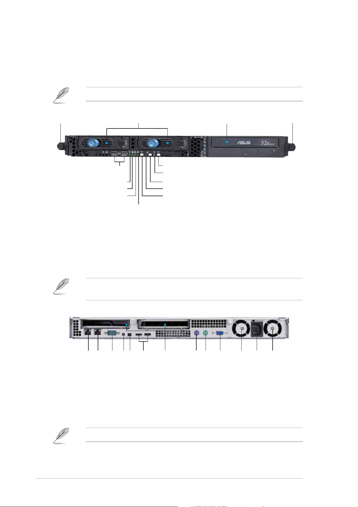
1.3 Front panel features
The barebone server displays a simple yet stylish front panel with easily
accessible features. The power and reset buttons, LED indicators, location
switch, optical drive, and two USB ports are located on the front panel.
Refer to section “1.6.2 Front panel LEDs” for the LED descriptions.
Rack screwRack screw
Rack screw
Rack screwRack screw
USB portsUSB ports
USB ports
USB portsUSB ports
HDD Access LEDHDD Access LED
HDD Access LED
HDD Access LEDHDD Access LED
LAN2 LEDLAN2 LED
LAN2 LED
LAN2 LEDLAN2 LED
LAN1 LEDLAN1 LED
LAN1 LED
LAN1 LEDLAN1 LED
Hot-swap HDD baysHot-swap HDD bays
Hot-swap HDD bays
Hot-swap HDD baysHot-swap HDD bays
Power buttonPower button
Power button
Power buttonPower button
Power LEDPower LED
Power LED
Power LEDPower LED
Location switchLocation switch
Location switch
Location switchLocation switch
Location LEDLocation LED
Location LED
Location LEDLocation LED
Reset buttonReset button
Reset button
Reset buttonReset button
Message LEDMessage LED
Message LED
Message LEDMessage LED
Optical driveOptical drive
Optical drive
Optical driveOptical drive
Rack screwRack screw
Rack screw
Rack screwRack screw
1.4 Rear panel features
The rear panel includes the expansion slots, system power socket, and rear
fans. The middle part includes the I/O shield with openings for the rear
panel connectors on the motherboard.
The ports for the PS/2 keyboard, PS/2 mouse, USB, VGA, and Gigabit
LAN do not appear on the rear panel if motherboard is not present.
1-41-4
1-4
1-41-4
Expansion slot
Expansion slotExpansion slot
LAN port1
LAN port1LAN port1
LAN port1LAN port1
Serial portSerial port
Serial portSerial port
LAN port2LAN port2
LAN port2LAN port2
Serial port
LAN port2
Locator LED
Locator switch
Locator LEDLocator LED
Locator switchLocator switch
Locator LEDLocator LED
Locator switchLocator switch
USB ports
USB portsUSB ports
USB portsUSB ports
Expansion slotExpansion slot
PS/2 mouse port
PS/2 keyboard port
PS/2 mouse portPS/2 mouse port
PS/2 mouse portPS/2 mouse port
PS/2 keyboard portPS/2 keyboard port
PS/2 keyboard portPS/2 keyboard port
VGA port
VGA portVGA port
VGA portVGA port
Power fan
Power fanPower fan
Power fanPower fan
Power fan
AC power socket
Power fanPower fan
Power fanPower fan
AC power socketAC power socket
AC power socketAC power socket
Refer to section “1.6.1 Rear panel LEDs” for the LED descriptions.
Chapter 1: Product introductionChapter 1: Product introduction
Chapter 1: Product introduction
Chapter 1: Product introductionChapter 1: Product introduction
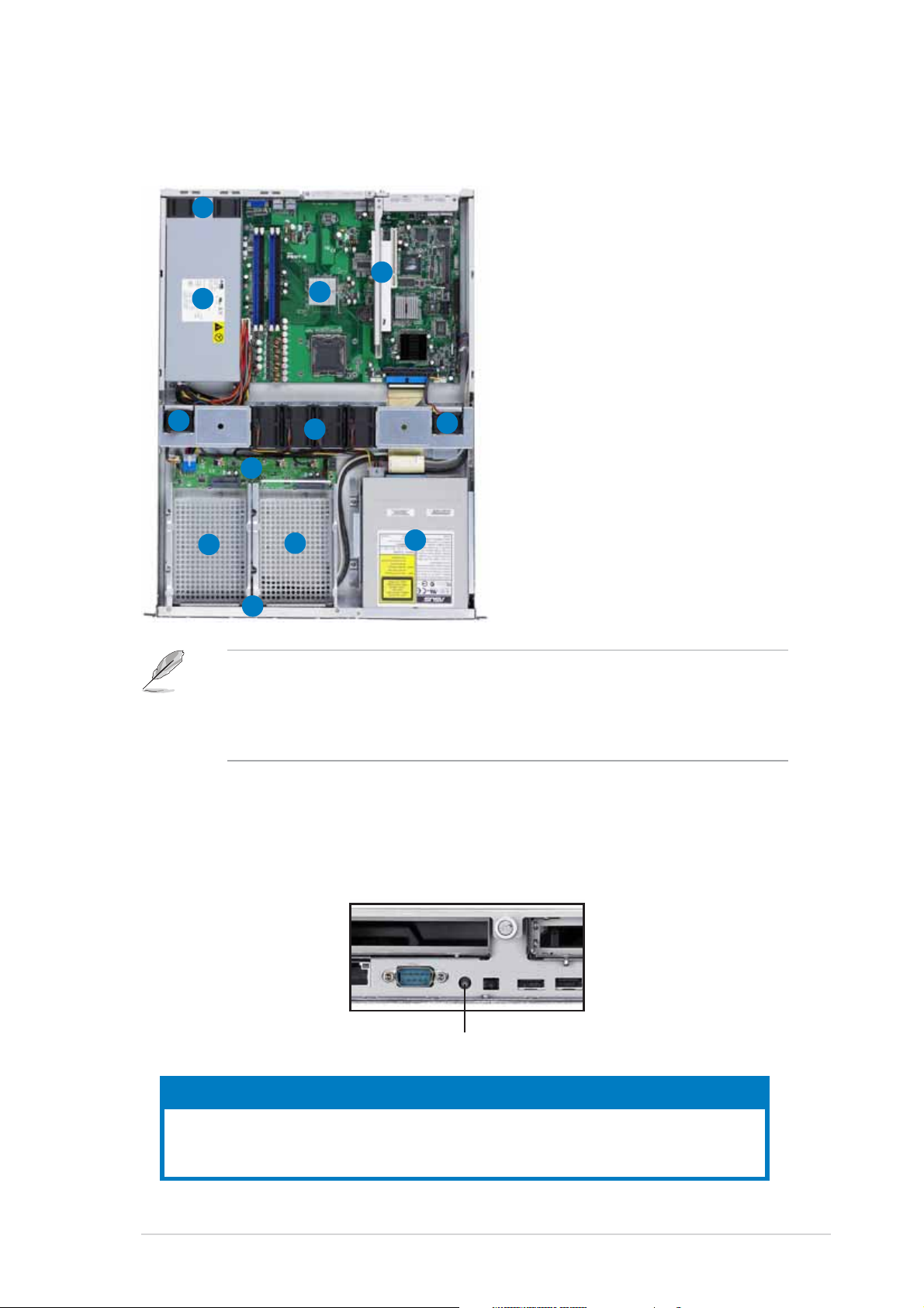
1.5 Internal features
The barebone server includes the basic components as shown.
22
2
22
1. PCI-X and PCI Express x8
riser card bracket
2. Power fans
11
1
11
33
3
44
4
44
33
3. ASUS P5MT-R motherboard
4. Power supply
5. Device fans (x 2)
6. System fans (x 4)
7. SATA backplane
55
5
55
66
6
66
55
5
55
8. Hot-swap HDD tray 1 Connects to SATA1 port
77
7
77
(Port0)
9. Hot-swap HDD tray 2 -
11
11
1
1
11
99
9
88
8
88
99
11
Connects to SATA3 port
(Port2)
10. Front I/O board (hidden)
1010
10
1010
11. Optical drive
• The barebone server does not include a floppy disk drive. Connect a
USB floppy disk drive to any of the USB ports on the front or rear
panel if you need to use a floppy disk.
• Only ASUS CD/DVD-ROMs fit the optical drive bay.
1.6 LED information
1.6.11.6.1
1.6.1
1.6.11.6.1
Rear panel LEDsRear panel LEDs
Rear panel LEDs
Rear panel LEDsRear panel LEDs
LEDLED
LED
LEDLED
Display statusDisplay status
Display status
Display statusDisplay status
Location LEDLocation LED
Location LED
Location LEDLocation LED
DescriptionDescription
Description
DescriptionDescription
Location LED OFF Normal status
ON Location switch is pressed
ASUS RS120-E3 (PA2)ASUS RS120-E3 (PA2)
ASUS RS120-E3 (PA2)
ASUS RS120-E3 (PA2)ASUS RS120-E3 (PA2)
(Press the location switch again to turn off)
1-51-5
1-5
1-51-5
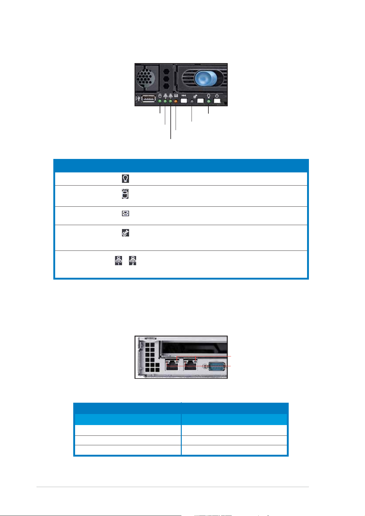
1.6.21.6.2
1.6.2
1.6.21.6.2
Front panel LEDsFront panel LEDs
Front panel LEDs
Front panel LEDsFront panel LEDs
HDD Access LEDHDD Access LED
HDD Access LED
HDD Access LEDHDD Access LED
LAN2 LEDLAN2 LED
LAN2 LED
LAN2 LEDLAN2 LED
Message LEDMessage LED
Message LED
Message LEDMessage LED
LAN1 LEDLAN1 LED
LAN1 LED
LAN1 LEDLAN1 LED
LEDLED
LED
LEDLED
Power LED ON System power ON
HDD Access LED OFF No activity
Message LED OFF System is normal; no incoming event
Location LED OFF Normal status
LAN LEDs OFF No LAN connection
IconIcon
Icon
IconIcon
Display statusDisplay status
Display status
Display statusDisplay status
Blinking Read/write data into the HDD
Blinking ASWM indicates a HW monitor event
ON Location switch is pressed
Blinking LAN is transmitting or receiving data
ON LAN connection is present
Power LEDPower LED
Power LED
Power LEDPower LED
Location LEDLocation LED
Location LED
Location LEDLocation LED
DescriptionDescription
Description
DescriptionDescription
(Press the location switch again to turn off)
1-61-6
1-6
1-61-6
1.6.31.6.3
1.6.3
1.6.31.6.3
LAN (RJ-45) LEDsLAN (RJ-45) LEDs
LAN (RJ-45) LEDs
LAN (RJ-45) LEDsLAN (RJ-45) LEDs
SPEED LEDSPEED LED
SPEED LED
SPEED LEDSPEED LED
ACT/LINK LEDACT/LINK LED
ACT/LINK LED
ACT/LINK LEDACT/LINK LED
ACT/LINK LEDACT/LINK LED
ACT/LINK LED
ACT/LINK LEDACT/LINK LED
StatusStatus
Status
StatusStatus
OFF No link OFF 10 Mbps connection
GREEN Linked ORANGE 100 Mbps connection
BLINKING Data activity GREEN 1 Gbps connection
DescriptionDescription
Description
DescriptionDescription
StatusStatus
Status
StatusStatus
Chapter 1: Product introductionChapter 1: Product introduction
Chapter 1: Product introduction
Chapter 1: Product introductionChapter 1: Product introduction
SPEED LEDSPEED LED
SPEED LED
SPEED LEDSPEED LED
DescriptionDescription
Description
DescriptionDescription
Chapter 2
This chapter lists the hardware
setup procedures that you have to
perform when installing or removing
system components.
ASUS RS120-E3 (PA2)ASUS RS120-E3 (PA2)
ASUS RS120-E3 (PA2)
ASUS RS120-E3 (PA2)ASUS RS120-E3 (PA2)
Hardware setup
2-1
2.1 Chassis cover
2.1.12.1.1
2.1.1
2.1.12.1.1
Removing the coverRemoving the cover
Removing the cover
Removing the coverRemoving the cover
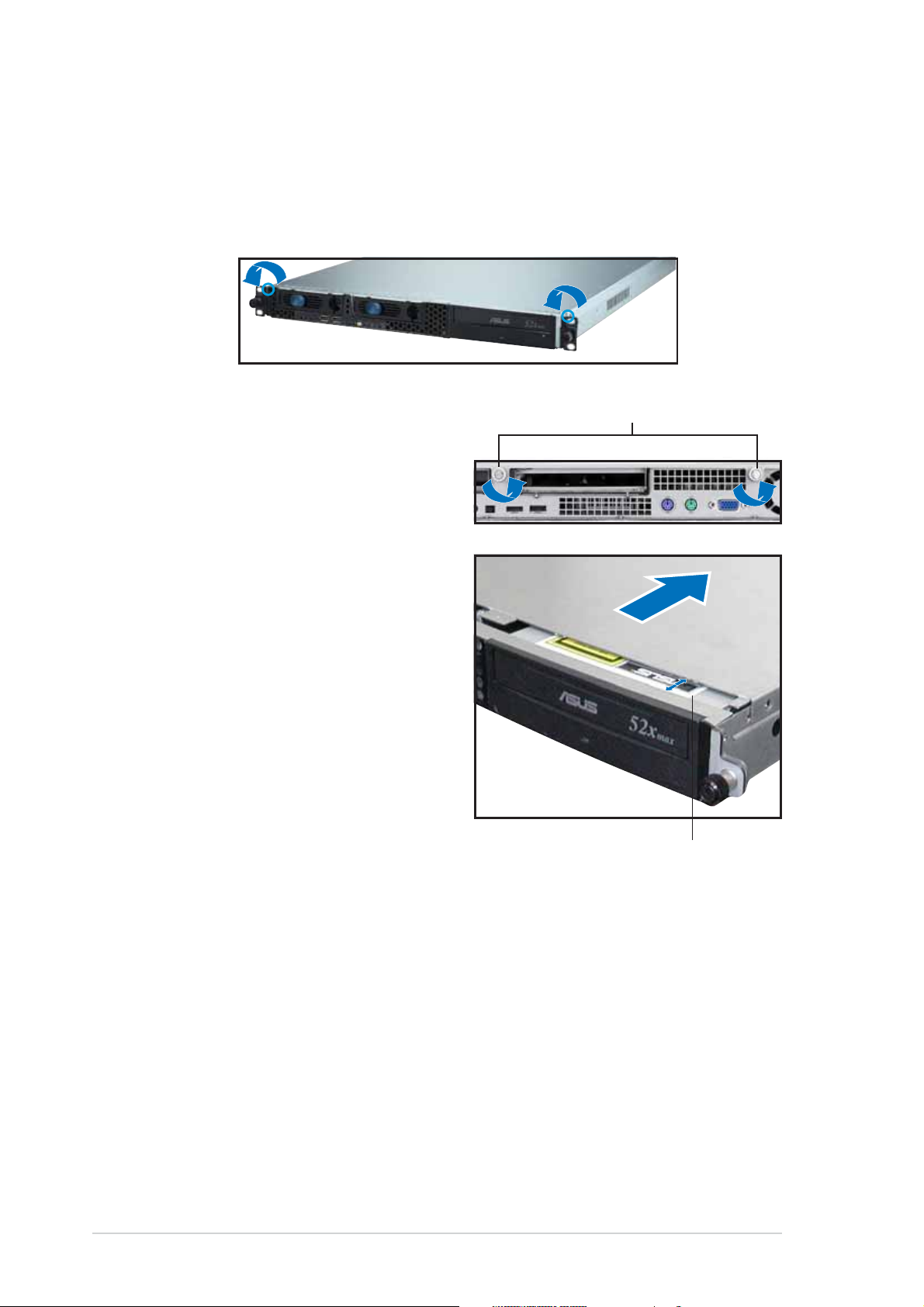
1. Use a Phillips screwdriver to remove the screw on each front end of
the top cover.
ThumbscrewsThumbscrews
Thumbscrews
2. Loosen the two thumbscrews
ThumbscrewsThumbscrews
on the rear panel to release the
top cover from the chassis.
3. Firmly hold the cover and slide it
toward the rear panel for about
half an inch until it is disengaged
from the chassis.
4. Lift the cover from the chassis.
2-22-2
2-2
2-22-2
1/2 inch distance1/2 inch distance
1/2 inch distance
1/2 inch distance1/2 inch distance
Chapter 2: Hardware setupChapter 2: Hardware setup
Chapter 2: Hardware setup
Chapter 2: Hardware setupChapter 2: Hardware setup
2.1.22.1.2
2.1.2
2.1.22.1.2
Installing the coverInstalling the cover
Installing the cover
Installing the coverInstalling the cover
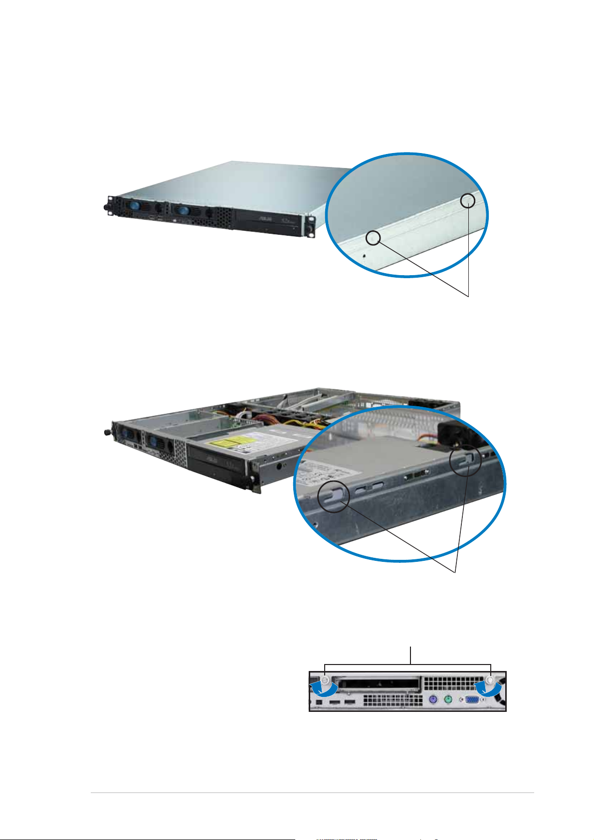
1. Position the cover on top of the chassis with the thumbscrews on the
rear, and leaving a gap of about half an inch from the front panel.
Side markingsSide markings
Side markings
Side markingsSide markings
2. Make sure that the side markings on the cover (two on each side) are
aligned to the grooves on the chassis.
GroovesGrooves
Grooves
GroovesGrooves
3. Slide the cover toward the front until it snaps in place.
ThumbscrewsThumbscrews
Thumbscrews
4. Tighten the thumbscrews on
ThumbscrewsThumbscrews
the rear to secure the cover.
ASUS RS120-E3 (PA2)ASUS RS120-E3 (PA2)
ASUS RS120-E3 (PA2)
ASUS RS120-E3 (PA2)ASUS RS120-E3 (PA2)
2-32-3
2-3
2-32-3
2.2 Central Processing Unit (CPU)
The system motherboard comes with a surface mount LGA775 socket
designed for Intel® Pentium® 4 or Pentium® D processor in the 775-land
package.
•
Upon purchase of the motherboard, make sure that the PnP cap is
on the socket and the socket contacts are not bent. Contact your
retailer immediately if the PnP cap is missing, or if you see any
damage to the PnP cap/socket contacts/motherboard components.
ASUS will shoulder the cost of repair only if the damage is shipment/
transit-related.
•
Keep the cap after installing the motherboard. ASUS will process
Return Merchandise Authorization (RMA) requests only if the
motherboard comes with the cap on the LGA775 socket.
• The product warranty does not cover damage to the socket
contacts resulting from incorrect CPU installation/removal, or
misplacement/loss/incorrect removal of the PnP cap.
2.2.12.2.1
2.2.1
2.2.12.2.1
Installing the CPUInstalling the CPU
Installing the CPU
Installing the CPUInstalling the CPU
To install a CPU:
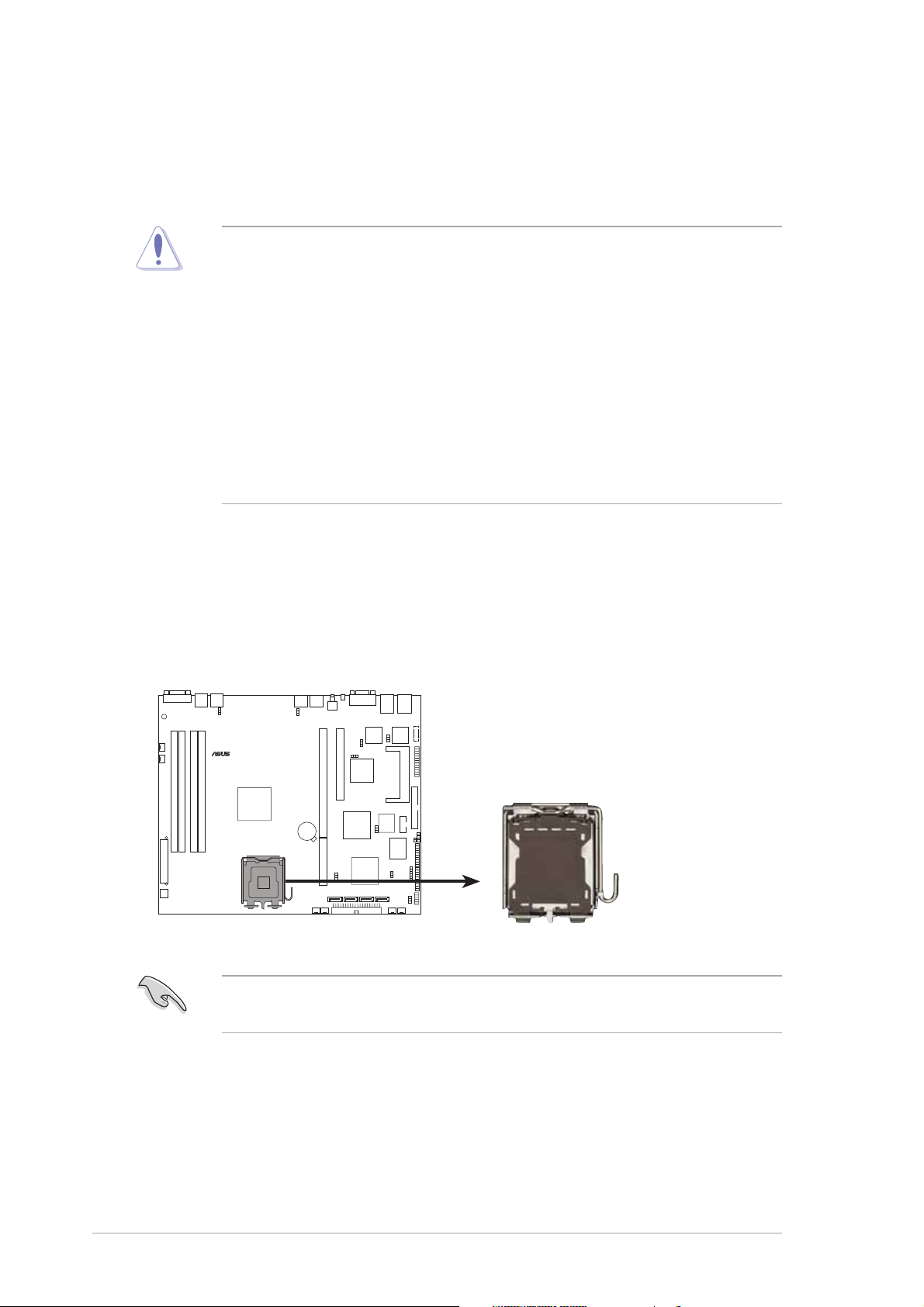
1. Locate the CPU socket on the motherboard.
®
P5MT-R
P5MT-R CPU Socket 775
Before installing the CPU, make sure that the cam box is facing towards
you and the load lever is on your left.
2-42-4
2-4
2-42-4
Chapter 2: Hardware setupChapter 2: Hardware setup
Chapter 2: Hardware setup
Chapter 2: Hardware setupChapter 2: Hardware setup
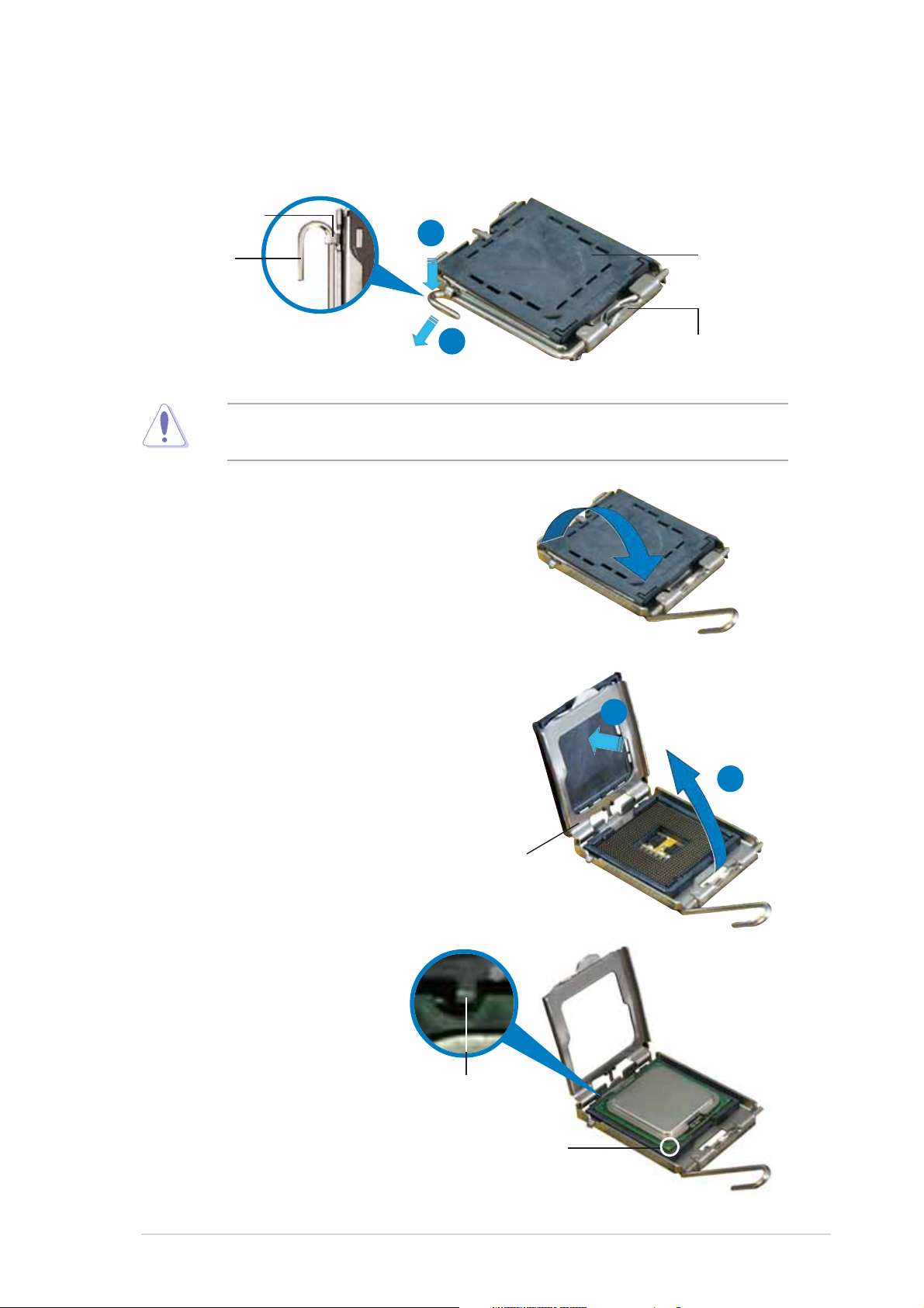
2. Press the load lever with your thumb (A), then move it to the left (B)
until it is released from the retention tab.
Retention tabRetention tab
Retention tab
Retention tabRetention tab
A
PnP capPnP cap
PnP cap
Load leverLoad lever
Load lever
Load leverLoad lever
PnP capPnP cap
To prevent damage to the socket pins, do not remove the PnP cap
unless you are installing a CPU.
3. Lift the load lever in the
direction of the arrow to a 135º
angle.
4. Lift the load plate with your
thumb and forefinger to a 100º
angle (A), then push the PnP cap
from the load plate window to
remove (B).
B
This side of theThis side of the
This side of the
This side of theThis side of the
socket box shouldsocket box should
socket box should
socket box shouldsocket box should
face you.face you.
face you.
face you.face you.
B
A
5. Position the CPU over
the socket, making sure
that the gold triangle is
on the bottom-left
corner of the socket.
The socket alignment
key should fit into the
CPU notch.
ASUS RS120-E3 (PA2)ASUS RS120-E3 (PA2)
ASUS RS120-E3 (PA2)
ASUS RS120-E3 (PA2)ASUS RS120-E3 (PA2)
Load plateLoad plate
Load plate
Load plateLoad plate
Alignment keyAlignment key
Alignment key
Alignment keyAlignment key
Gold triangle markGold triangle mark
Gold triangle mark
Gold triangle markGold triangle mark
2-52-5
2-5
2-52-5
The CPU fits in only one correct orientation. DO NOT force the CPU into
the socket to prevent bending the connectors on the socket and
damaging the CPU!
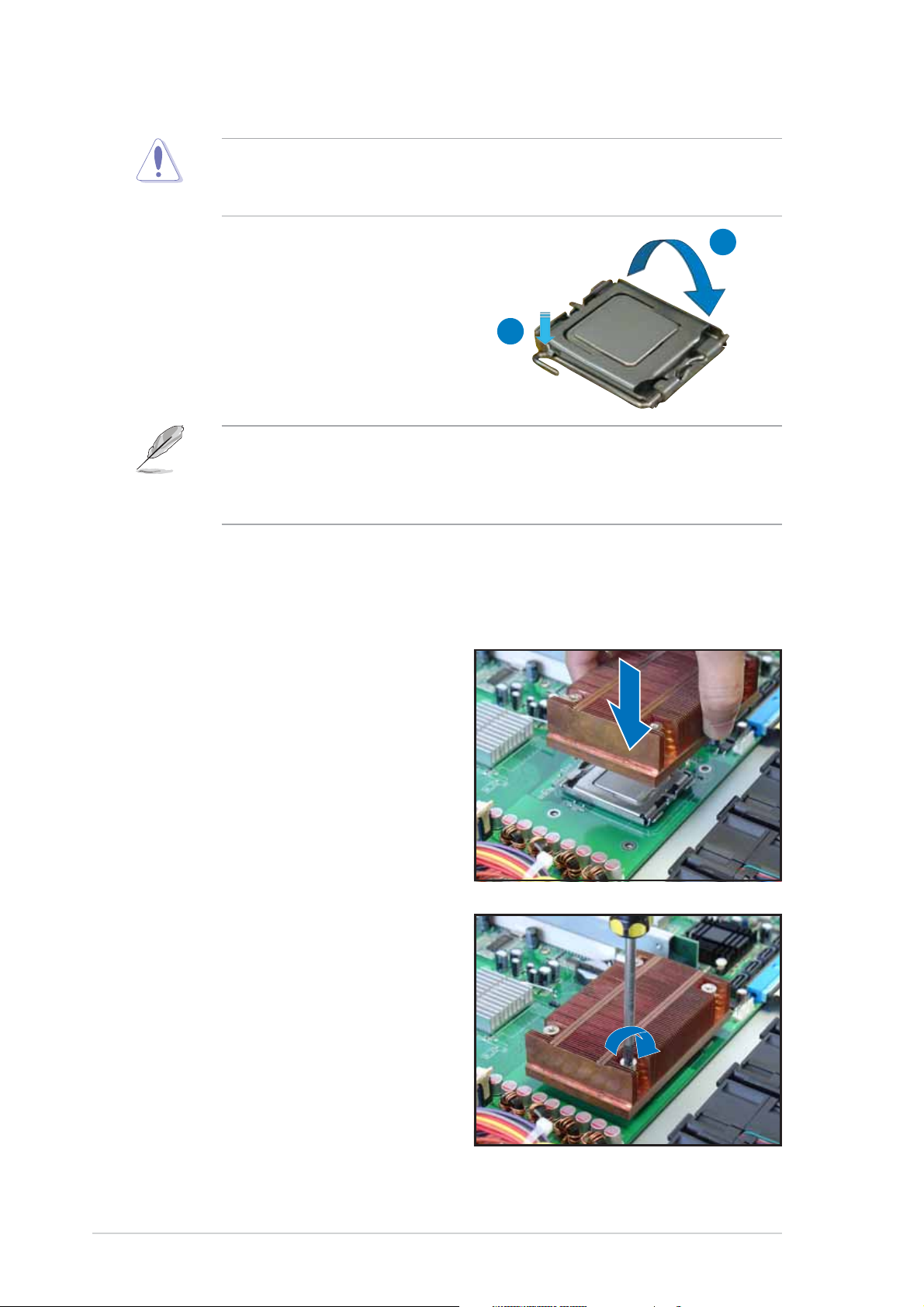
6. Close the load plate (A), then
push the load lever (B) until it
snaps into the retention tab.
The motherboard supports Intel® Pentium® 4 LGA775 processors with
the Intel® Enhanced Memory 64 Technology (EM64T), Enhanced Intel
SpeedStep® Technology (EIST), and Hyper-Threading Technology. Refer
to the Appendix for more information on these CPU features.
A
B
2.2.22.2.2
2.2.2
2.2.22.2.2
Installing the CPU heatsink and airductInstalling the CPU heatsink and airduct
Installing the CPU heatsink and airduct
Installing the CPU heatsink and airductInstalling the CPU heatsink and airduct
To install the CPU heatsink:
1. Carefully place the heatsink on
top of the installed CPU.
2. Twist each of the four screws
with a Philips (cross) screwdriver
just enough to attach the
heatsink to the motherboard.
When the four screws are
attached, tighten them one by
one to completely secure the
heatsink.
2-62-6
2-6
2-62-6
Chapter 2: Hardware setupChapter 2: Hardware setup
Chapter 2: Hardware setup
Chapter 2: Hardware setupChapter 2: Hardware setup
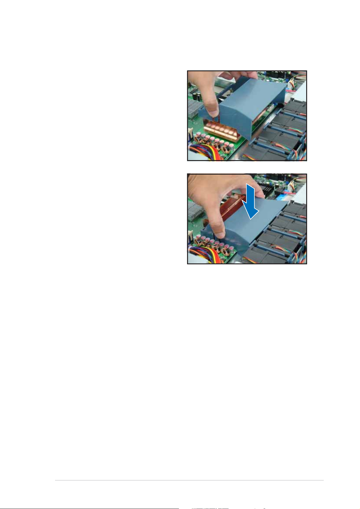
To install the airduct:
1. Position the airduct on top of
the heatsink.
2. Carefully lower the airduct until
it fits in place.
ASUS RS120-E3 (PA2)ASUS RS120-E3 (PA2)
ASUS RS120-E3 (PA2)
ASUS RS120-E3 (PA2)ASUS RS120-E3 (PA2)
2-72-7
2-7
2-72-7
2.3 System memory
2.3.12.3.1
2.3.1
2.3.12.3.1
DIMM sockets locationDIMM sockets location
DIMM sockets location
DIMM sockets locationDIMM sockets location
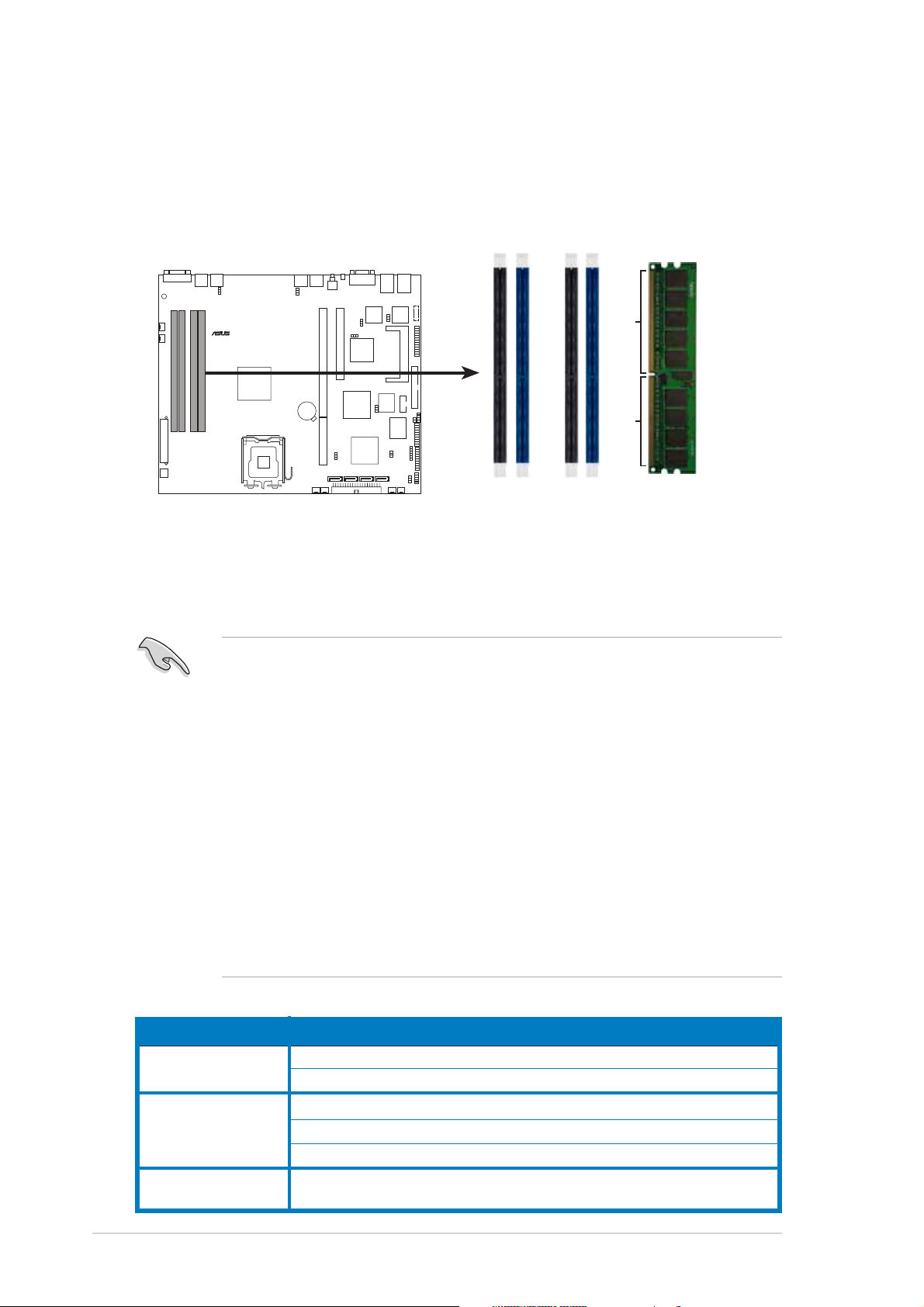
The system motherboard comes with four Double Data Rate II (DDR2) Dual
Inline Memory Modules (DIMM) sockets to support 240-pin DDR2 modules.
The figure illustrates the location of the DDR2 DIMM sockets:
®
P5MT-R
112 Pins 128 Pins
P5MT-R 240-pin DDR2 DIMM sockets
2.3.22.3.2
2.3.2
2.3.22.3.2
Memory configurationsMemory configurations
Memory configurations
Memory configurationsMemory configurations
DIMM_B2
DIMM_B1
DIMM_A2
DIMM_A1
You may install 256 MB, 512 MB, 1 GB, and 2 GB unbuffered ECC or
non-ECC DDR2-533/667 DIMMs to the DIMM sockets.
• Always install DIMMs with the same CAS latency. For optimum
compatibility, it is recommended that you obtain memory modules
from the same vendor. Visit the ASUS website for an updated DDR2
Qualified Vendors List for this motherboard.
• Due to chipset resource allocation, and depending on the number of
expansion cards installed, the following conditions may occur:
- the system may detect less than 8 GB system memory when
you installed four 2 GB DDR2 memory modules
- may show an available memory space of less than 4 GB when
you installed four 1 GB DDR2 memory modules
• Three DDR2 DIMMs installed into any three memory sockets will
function in Dual channel asymmetric mode.
• When installing a single or two DIMMs, install the modules on the
blue slots (DIMM_A2/DIMM_B2). Refer to the recommended memory
configuration table below.
Recommended memory configurationsRecommended memory configurations
Recommended memory configurations
Recommended memory configurationsRecommended memory configurations
ModeMode
Mode
ModeMode
Single channel (1) — populated — —
(2) — — — populated
DIMM_A1DIMM_A1
DIMM_A1
DIMM_A1DIMM_A1
DIMM_A2DIMM_A2
DIMM_A2
DIMM_A2DIMM_A2
DIMM_B1DIMM_B1
DIMM_B1
DIMM_B1DIMM_B1
DIMM_B2DIMM_B2
DIMM_B2
DIMM_B2DIMM_B2
2-82-8
2-8
2-82-8
Dual channel (1) populated — populated —
(2) — populated — populated
(3) populated populated populated populated
Dual channel (1) populated populated — populated
(Asymmetric mode)
Chapter 2: Hardware setupChapter 2: Hardware setup
Chapter 2: Hardware setup
Chapter 2: Hardware setupChapter 2: Hardware setup
2.3.32.3.3
2.3.3
2.3.32.3.3
Installing a DIMMInstalling a DIMM
Installing a DIMM
Installing a DIMMInstalling a DIMM
Make sure to unplug the power supply before adding or removing DIMMs
or other system components. Failure to do so may cause severe damage
to both the motherboard and the components.
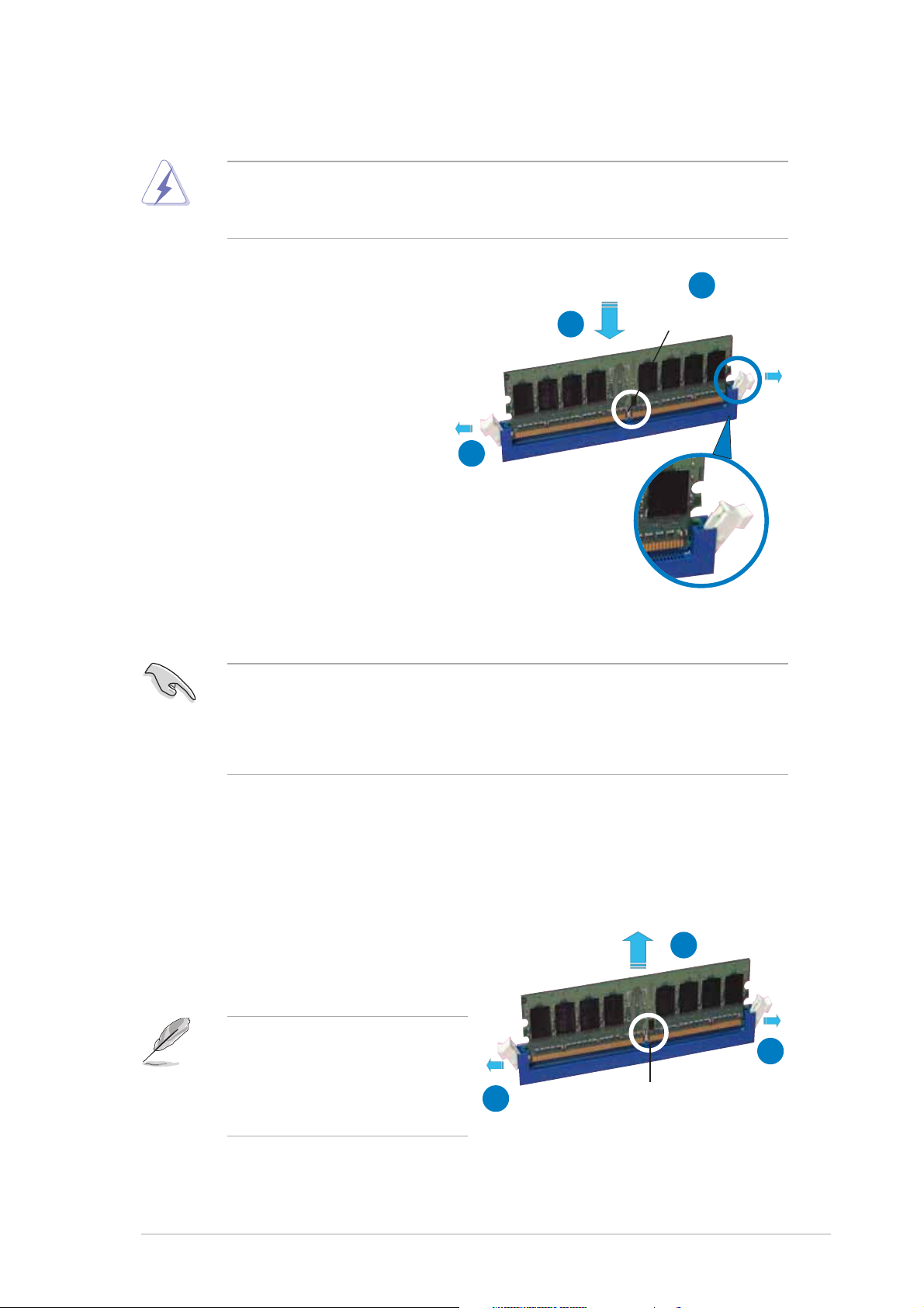
To install a DIMM:
1. Unlock a DIMM socket by
pressing the retaining clips
outward.
2. Align a DIMM on the socket
such that the notch on the
DIMM matches the break on
the socket.
3. Firmly insert the DIMM into
the socket until the retaining
clips snap back in place and
the DIMM is properly seated.
2
DDR2 DIMM notchDDR2 DIMM notch
DDR2 DIMM notch
3
1
Unlocked retaining clipUnlocked retaining clip
Unlocked retaining clip
Unlocked retaining clipUnlocked retaining clip
DDR2 DIMM notchDDR2 DIMM notch
• A DDR2 DIMM is keyed with a notch so that it fits in only one direction.
Do not force a DIMM into a socket to avoid damaging the DIMM.
• The DDR2 DIMM sockets do not support DDR DIMMs. DO NOT install
DDR DIMMs to the DDR2 DIMM sockets.
2.3.42.3.4
2.3.4
2.3.42.3.4
Removing a DIMMRemoving a DIMM
Removing a DIMM
Removing a DIMMRemoving a DIMM
Follow these steps to remove a DIMM.
1. Simultaneously press the
retaining clips outward to unlock
the DIMM.
Support the DIMM lightly with
your fingers when pressing the
retaining clips. The DIMM
might get damaged when it
flips out with extra force.
2
1
DDR2 DIMM notchDDR2 DIMM notch
DDR2 DIMM notch
1
DDR2 DIMM notchDDR2 DIMM notch
2. Remove the DIMM from the socket.
ASUS RS120-E3 (PA2)ASUS RS120-E3 (PA2)
ASUS RS120-E3 (PA2)
ASUS RS120-E3 (PA2)ASUS RS120-E3 (PA2)
2-92-9
2-9
2-92-9
2.4 Hard disk drives
The system supports two hot-swap Serial ATA hard disk drives. The hard
disk drive installed on the left tray connects to the motherboard SATA1
(Port0) port, while the right tray hard disk drive connects to the
motherboard SATA3 (Port2) port via the SATA backplane.
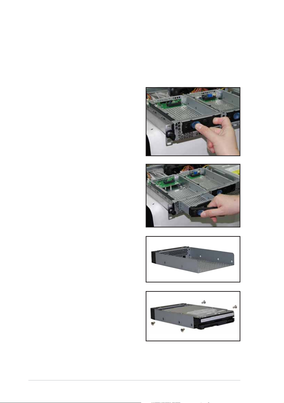
To install a hot-swap SATA HDD:
1. Release a drive tray by pushing
the spring lock to the right,
then pulling the tray lever
outward. The drive tray ejects
slightly after you pull out the
lever.
2. Firmly hold the tray lever and
pull the drive tray out of the
bay.
3. Take note of the drive tray
holes. Each side has three holes
to fit different types of hard
disk drives. Use two screws on
each side to secure the hard
disk drive.
4. Place a SATA hard disk drive on
the tray, then secure it with
four screws.
2-102-10
2-10
2-102-10
Chapter 2: Hardware setupChapter 2: Hardware setup
Chapter 2: Hardware setup
Chapter 2: Hardware setupChapter 2: Hardware setup
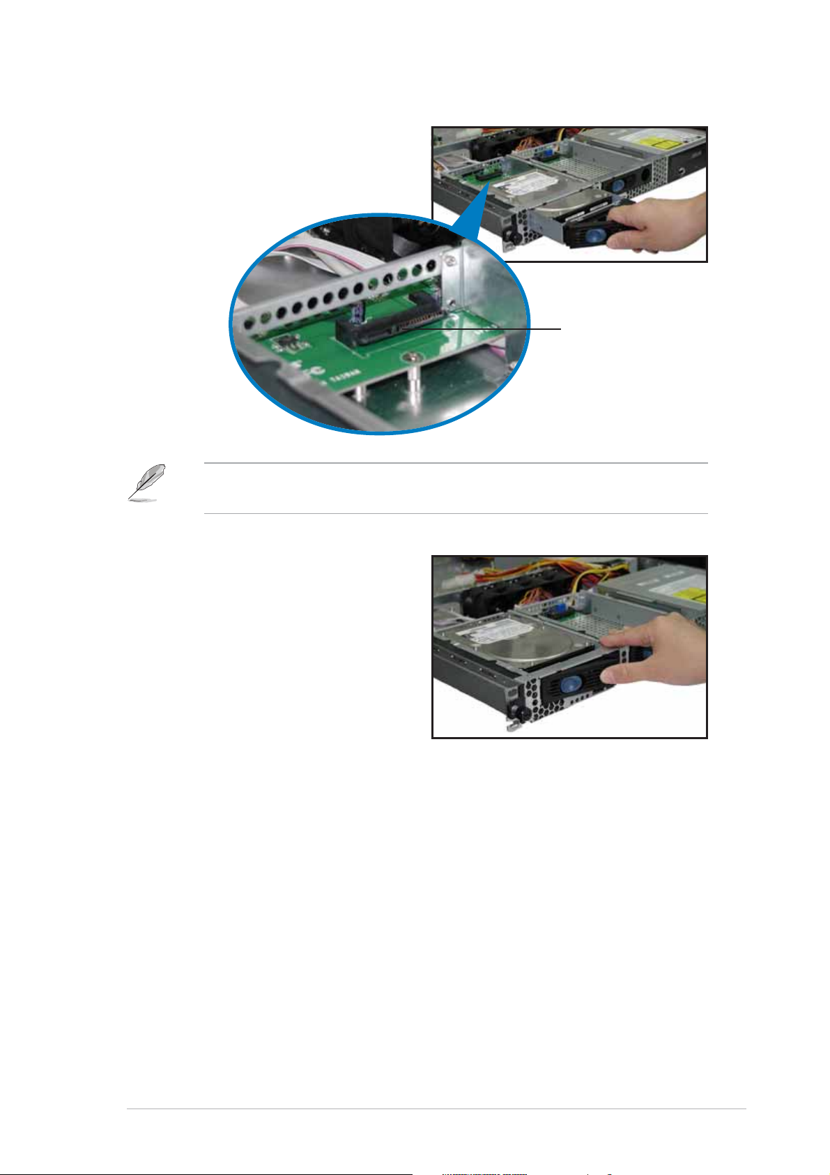
5. Carefully insert the drive tray
and push it all the way to the
depth of the bay until just a
small fraction of the tray edge
protrudes.
When installed, the SATA connector on the drive connects to the SATA
interface on the backplane.
SATA interfaceSATA interface
SATA interface
SATA interfaceSATA interface
on the backplaneon the backplane
on the backplane
on the backplaneon the backplane
6. Push the tray lever until it
clicks, and secures the drive
tray in place. The drive tray is
correctly placed when its front
edge aligns with the bay edge.
7. Repeat steps 1 to 6 if you wish
to install a second SATA drive.
8. Connect the bundled SATA cables to the connectors on the SATA
backplane. Refer to section “2.7 SATA backplane cabling” for
information on the SATA backplane cable connections.
ASUS RS120-E3 (PA2)ASUS RS120-E3 (PA2)
ASUS RS120-E3 (PA2)
ASUS RS120-E3 (PA2)ASUS RS120-E3 (PA2)
2-112-11
2-11
2-112-11
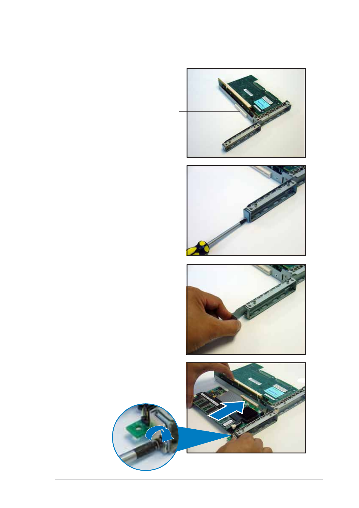
2.5 Expansion slot
2.5.12.5.1
2.5.1
2.5.12.5.1
The barebone server comes with a riser card bracket. You need to remove
the bracket if you want to install a PCI-X and/or a PCI Express x8 expansion
cards.
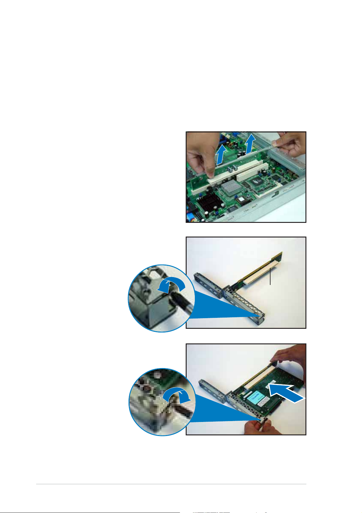
To install a PCI-X card:
1. Firmly hold the riser card
bracket, then pull it up to
detach it from the PCI Express
x8 and PCI-X slots on the
motherboard.
Installing an expansion card to theInstalling an expansion card to the
Installing an expansion card to the
Installing an expansion card to theInstalling an expansion card to the
riser card bracketriser card bracket
riser card bracket
riser card bracketriser card bracket
2. Place the riser card bracket on a
flat and stable surface, then
remove the screw from the
PCI-X slot bay.
3. Install a PCI-X card to the
bracket as shown, then secure
the card with a screw.
PCI-X slotPCI-X slot
PCI-X slot
PCI-X slotPCI-X slot
2-122-12
2-12
2-122-12
Chapter 2: Hardware setupChapter 2: Hardware setup
Chapter 2: Hardware setup
Chapter 2: Hardware setupChapter 2: Hardware setup
To install a PCI Express x8 card:
1. Follow steps 1 to 2 of the
previous section.
PCI Express x8 slotPCI Express x8 slot
PCI Express x8 slot
PCI Express x8 slotPCI Express x8 slot
2. Use a Phillips (cross)
screwdriver to remove the
screw that secures the slot
metal cover.
3. Remove the slot metal cover,
then set it aside.
4. Install a PCI Express x8 card to
the bracket as shown, then
secure the card with a screw
you removed earlier.
ASUS RS120-E3 (PA2)ASUS RS120-E3 (PA2)
ASUS RS120-E3 (PA2)
ASUS RS120-E3 (PA2)ASUS RS120-E3 (PA2)
2-132-13
2-13
2-132-13
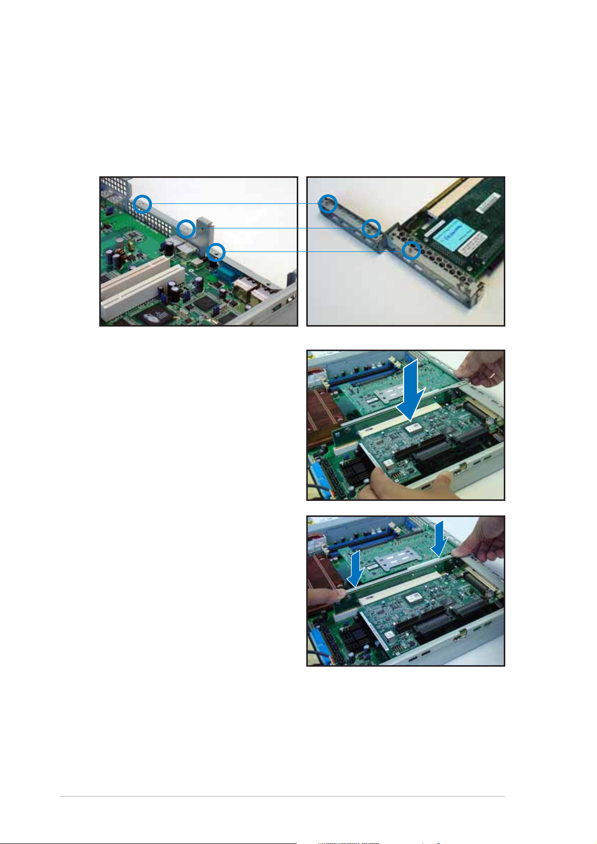
2.5.22.5.2
2.5.2
2.5.22.5.2
Reinstalling the riser card bracketReinstalling the riser card bracket
Reinstalling the riser card bracket
Reinstalling the riser card bracketReinstalling the riser card bracket
To reinstall the riser card bracket:
1. Take note of the holes on the riser card bay. The three pegs on the
riser card bracket should match these holes to ensure that the
bracket is properly in place.
Pegs on the riserPegs on the riser
Pegs on the riser
Pegs on the riserPegs on the riser
card bracketcard bracket
card bracket
card bracketcard bracket
2. Install the riser card bracket
with the card into the PCI
Express x8 and PCI-X slots on
the motherboard.
3. Press the riser card bracket until
the golden connectors
completely fit the slot and the
bracket aligns with the rear
panel.
4. Connect the cable(s) to the
card, if applicable.
2-142-14
2-14
2-142-14
Chapter 2: Hardware setupChapter 2: Hardware setup
Chapter 2: Hardware setup
Chapter 2: Hardware setupChapter 2: Hardware setup
 Loading...