How it Works
Log In / Sign Up
Buy Points
How it Works
FAQ
Contact Us
Questions and Suggestions
Users
ASUS
Loading...
R
ROG Maximus II Gene
ROG Maximus IX Apex
ROG Maximus IX Code
2
ROG Maximus VIII Hero Alpha
2
ROG Maximus VIII Impact
2
ROG Maximus VIII Ranger
ROG Maximus X Formula
ROG Maximus X Hero
ROG Maximus XI Extreme
ROG Maximus XI Formula
ROG Maximus XI Gene
2
ROG Maximus XI Hero
4
ROG Maximus XI Hero - Call of Duty - Black Ops 4 Edition
ROG MAXIMUS XI HERO (WI-FI)
2
ROG MAXIMUS XII APEX
2
ROG Maximus XII extreme
2
ROG Maximus XII Formula
2
ROG Maximus XII Hero
2
ROG Phone
3
Rog Phone 3
ROG PHONE E14163
ROG Phone II
2
ROG Phone ZS600 KL
ROG Phone ZS661KS
ROG Pugio
2
ROG Pugio II
ROG Radeon RX 570
ROG Rampage II Gene
ROG RAMPAGE V EDITION 10
4
ROG RAMPAGE VI APEX
5
ROG RAMPAGE VI EXTREME
7
ROG RAMPAGE VI Extreme Encore
7
ROG RAMPAGE VI EXTREME OMEGA
3
ROG Rapture GT-AC2900
3
ROG Rapture GT-AC5300
2
ROG Rapture GT-AX11000
4
ROG Ryuo 240
ROG Sagaris GK1100
ROG Scabbard
ROG Sica
2
ROG Spartha
ROG Spatha
2
ROG STRIX
ROG Strix Arion
ROG Strix B350-I Gaming
ROG Strix B360-F Gaming
2
ROG Strix B360-G Gaming
ROG Strix B360-H Gaming
ROG Strix B360-I Gaming
2
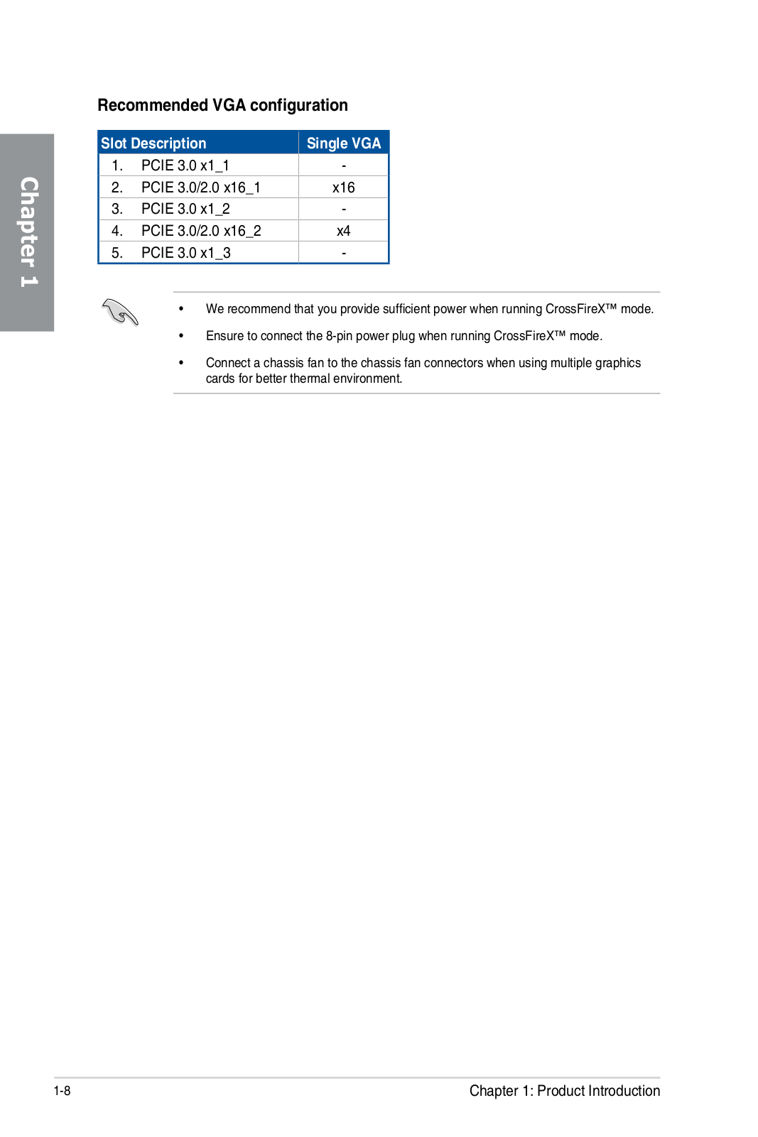
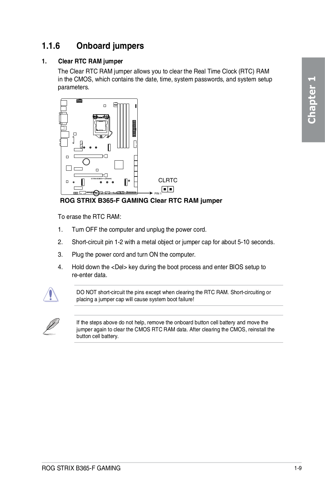
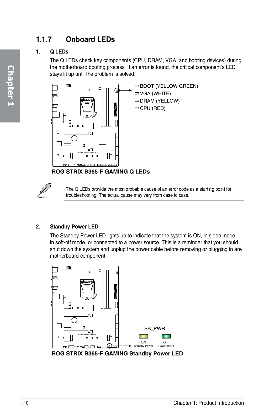
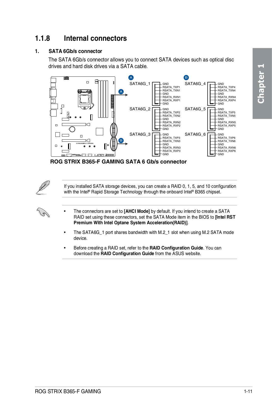
ROG Strix B365-F Gaming
ROG Strix B365-G Gaming
2
ROG Strix B450-E Gaming
2
ROG STRIX B450-F GAMING
3
ROG Strix B450-F Gaming II
ROG Strix B450-I Gaming
ROG Strix B460-F Gaming
2
ROG Strix B460-G Gaming
2
ROG Strix B460-H Gaming
2
ROG STRIX B460-I GAMING
2
ROG Strix B550-A Gaming
ROG STRIX B550-E
ROG Strix B550-E Gaming
2
ROG STRIX B550-F
ROG Strix B550-F Gaming
3
ROG STRIX B550-F GAMING WI-FI
ROG Strix B550-I Gaming
2
ROG Strix B550-XE Gaming WIFI
2
ROG Strix Carry
ROG Strix Edge
2
ROG Strix Evolve
2
ROG Strix Flare PINK
ROG STRIX Fusion
ROG Strix Fusion 300
3
ROG Strix Fusion 500
2
ROG Strix Fusion 700
2
ROG Strix Fusion Wireless
2
ROG Strix G
ROG Strix G15DH-NL028T
ROG Strix G15 G512LV-HN033T
ROG Strix G15 G512LW-HN055T
2
ROG Strix G17
ROG Strix G17 G712LWS-EV003
3
ROG Strix G35DX-NL013T
ROG Strix GA15 G15DH-DE008T
ROG Strix GA35 G35DX-DE005T
2
ROG Strix GL503GE-EN296T
ROG STRIX GL531GT-AL299T
ROG STRIX GL702VM
ROG Strix Go USB-C
ROG Strix H370-F Gaming
2
ROG Strix H370-I Gaming
2
ROG Strix H470-I Gaming
2
ROG STRIX HELIOS
ROG Strix Hero II
ROG Strix Hero II GL504GM-BN328
ROG Strix Hero II GL504GM-BN328T
ROG Strix Hero II GL504GM-BN337
ROG Strix Hero II GL504GV-ES117
ROG Strix LC 120
2
ROG Strix LC 360
Loading...
Loading...
Nothing found
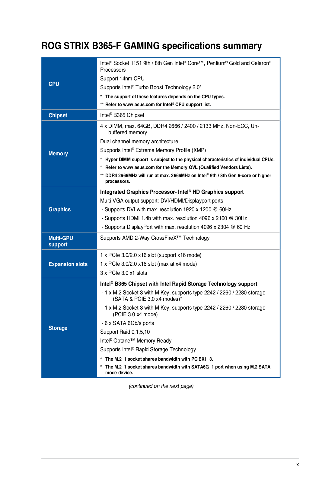
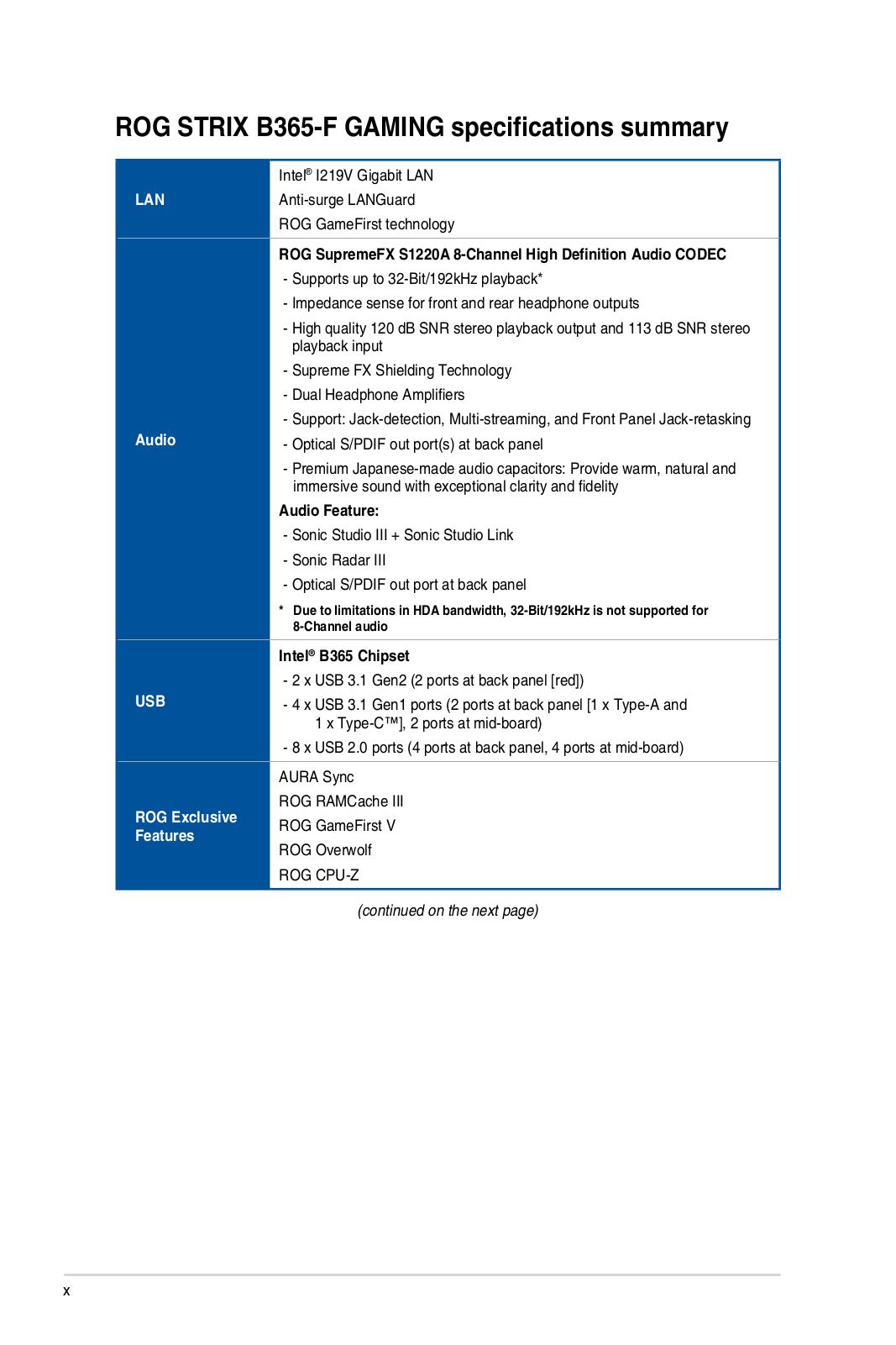
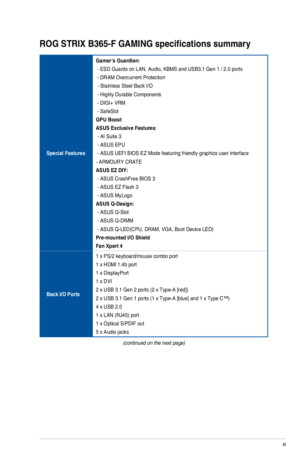
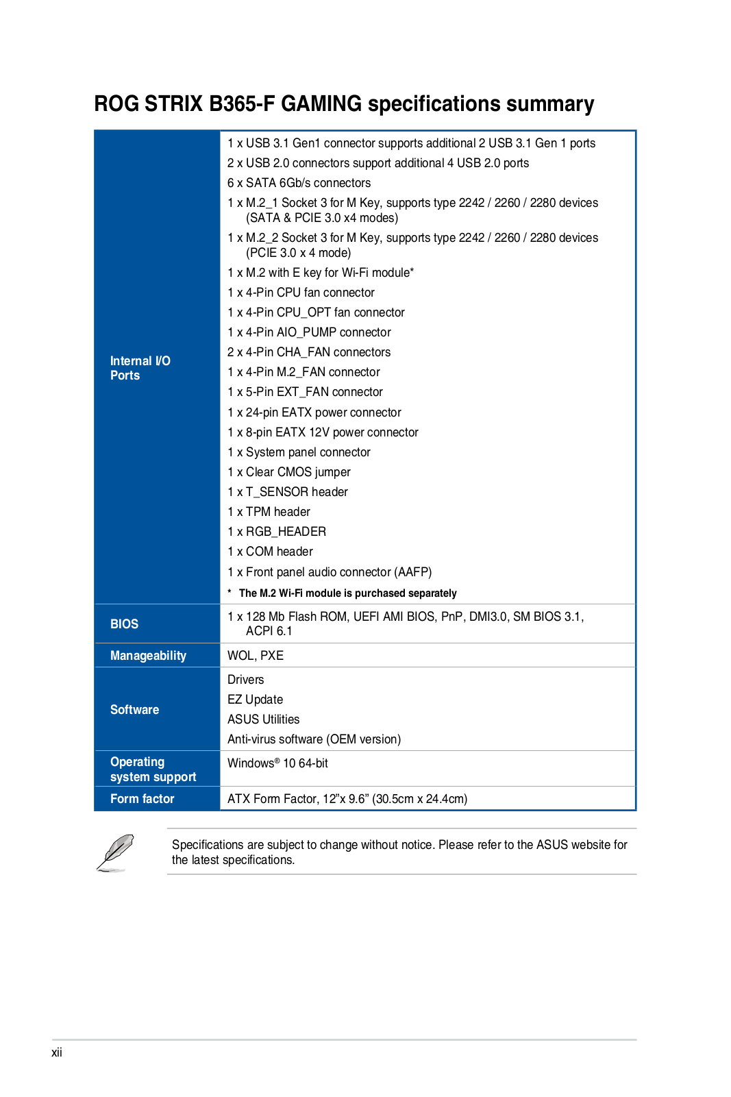
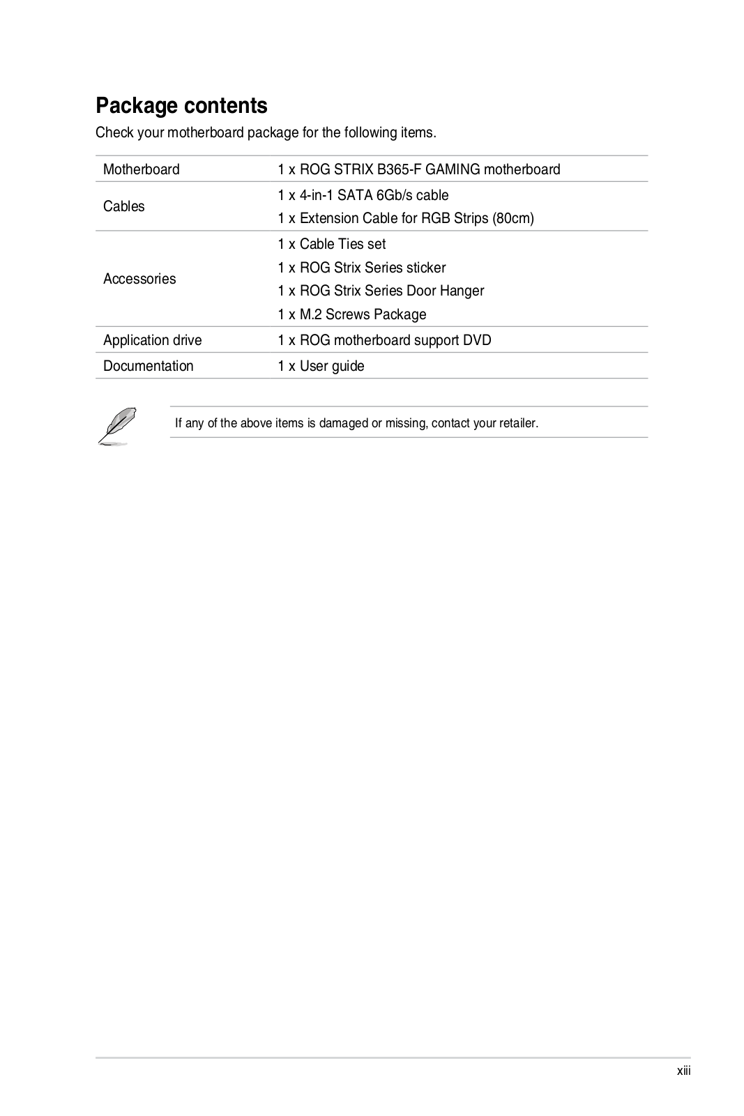
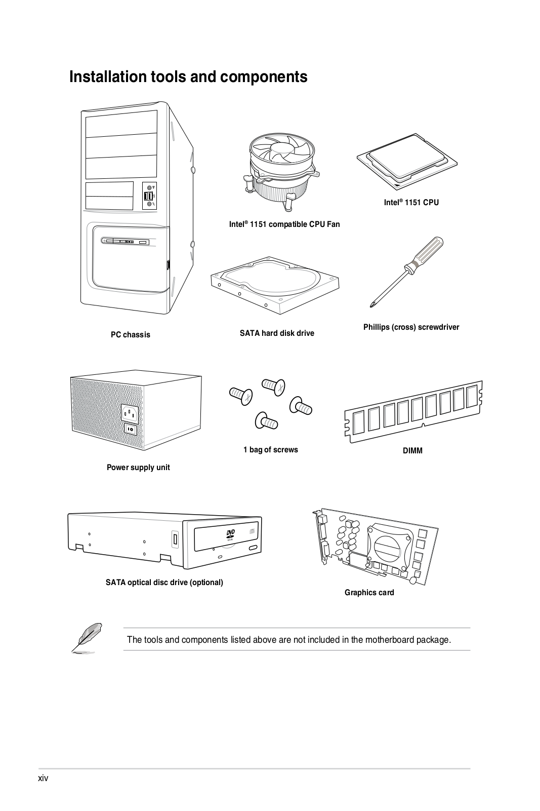
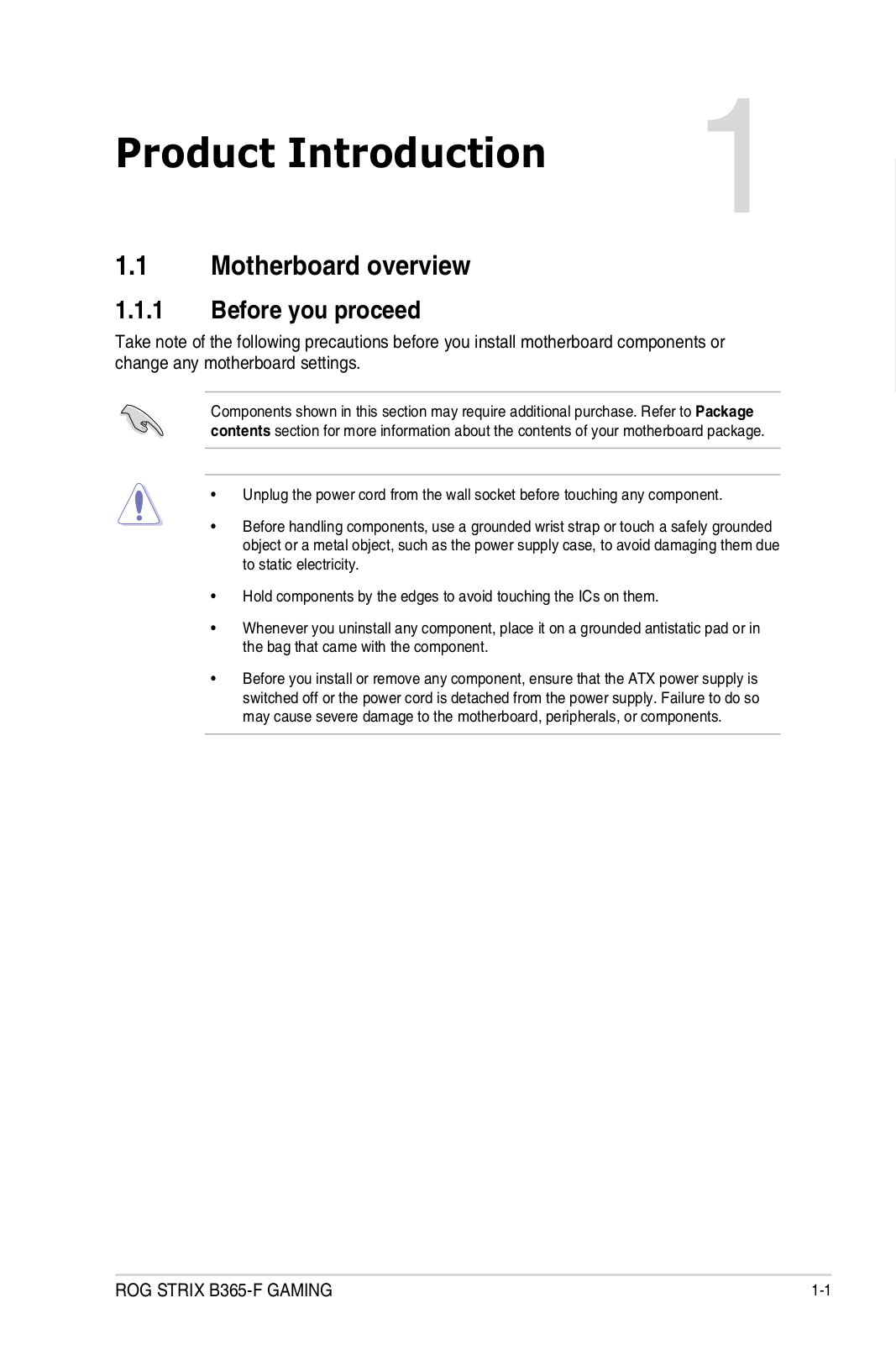
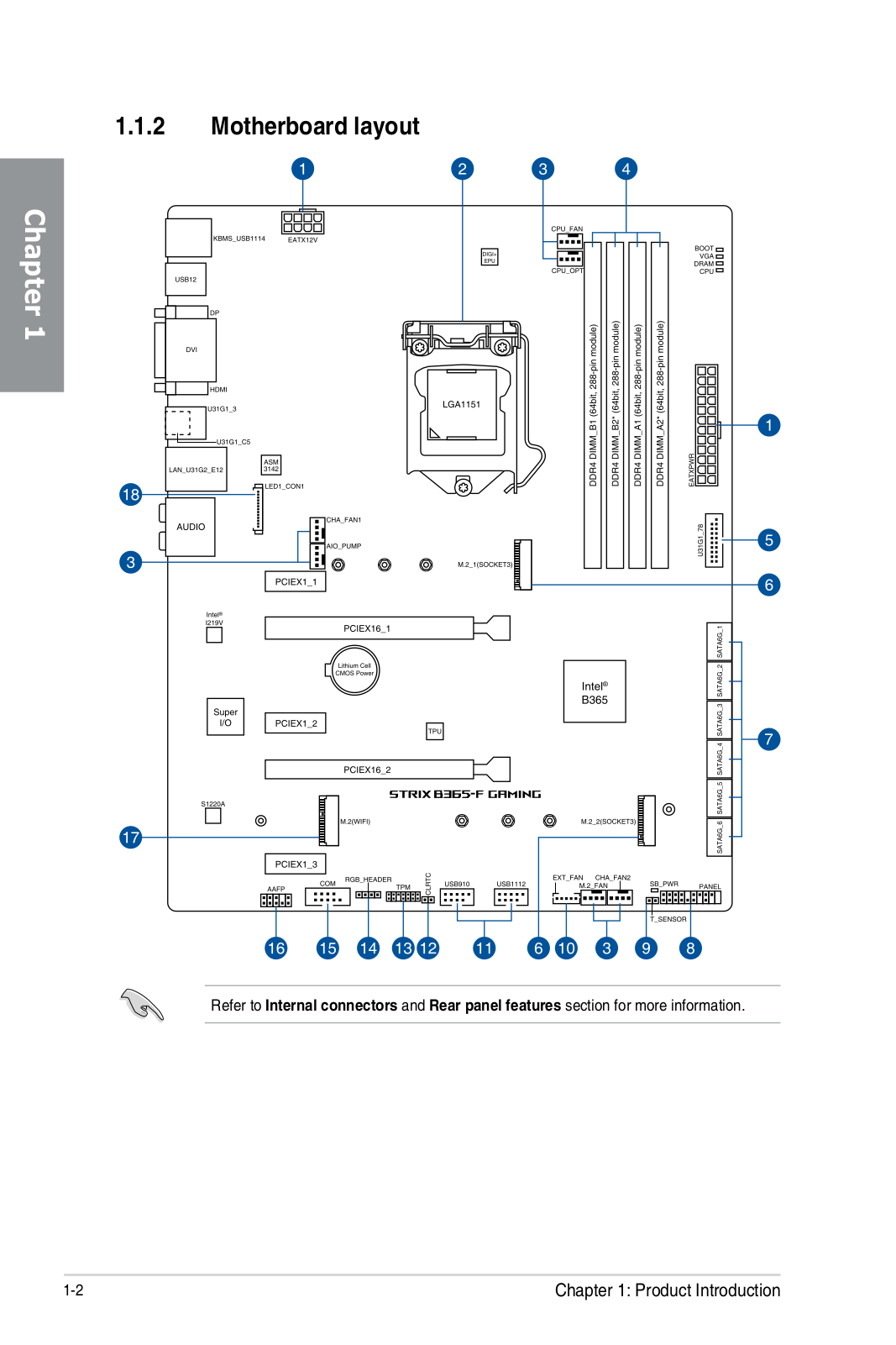
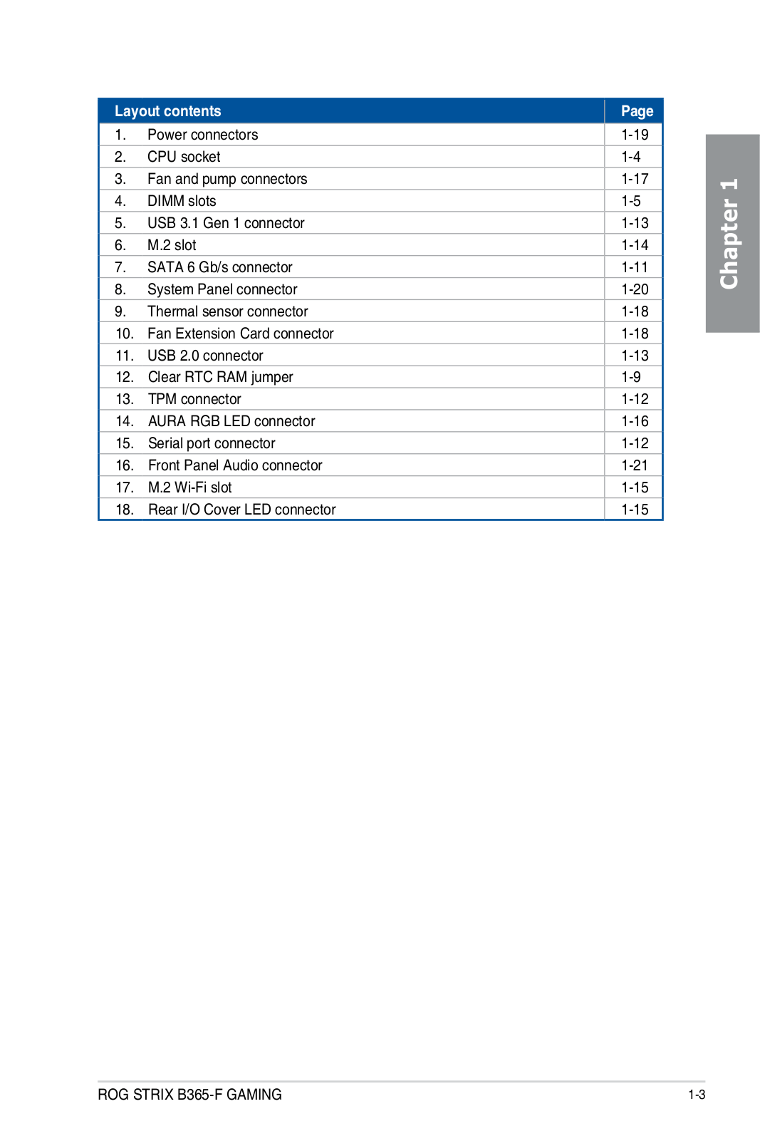
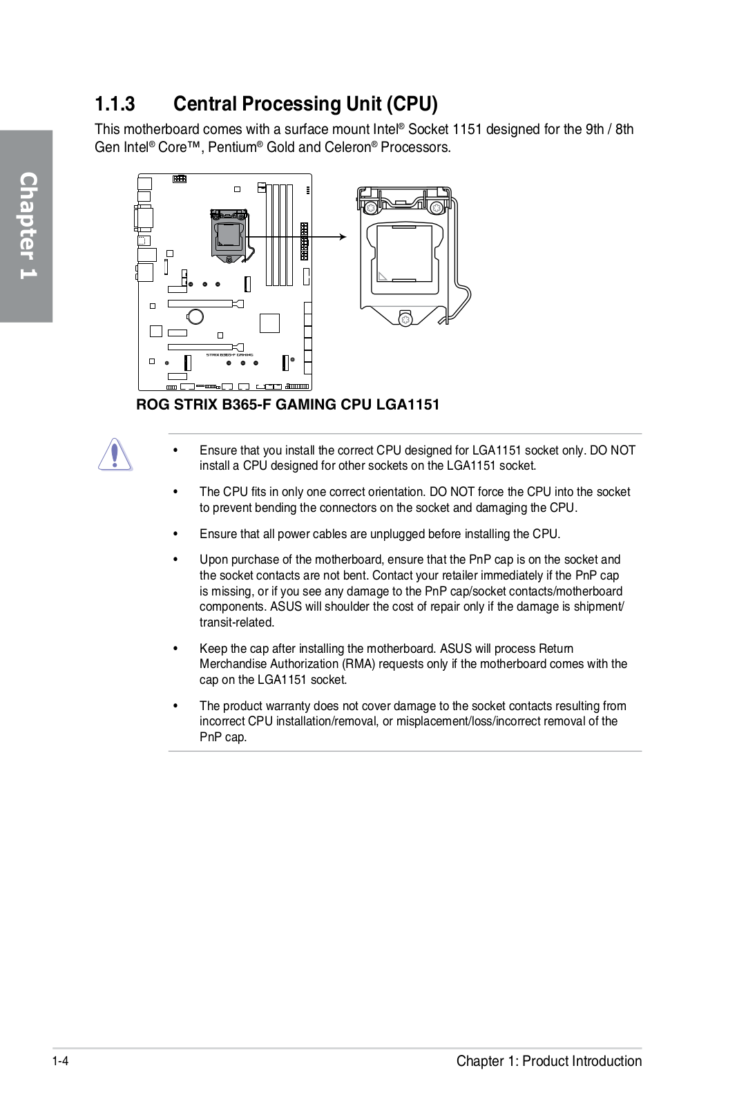
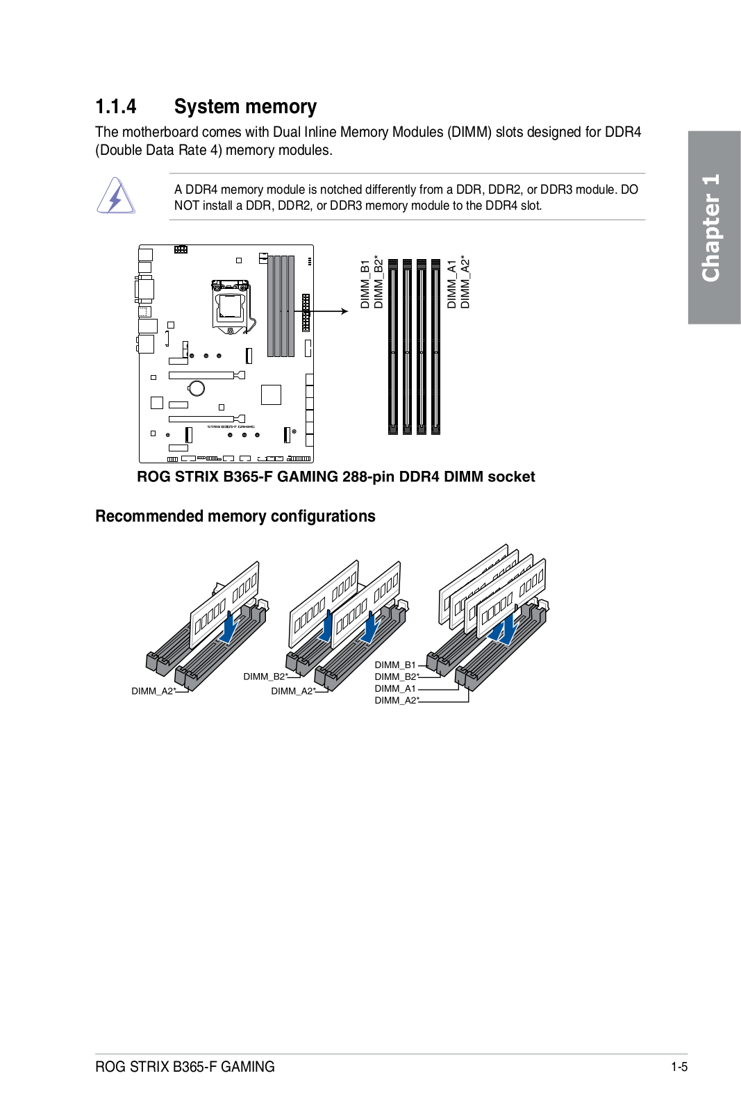
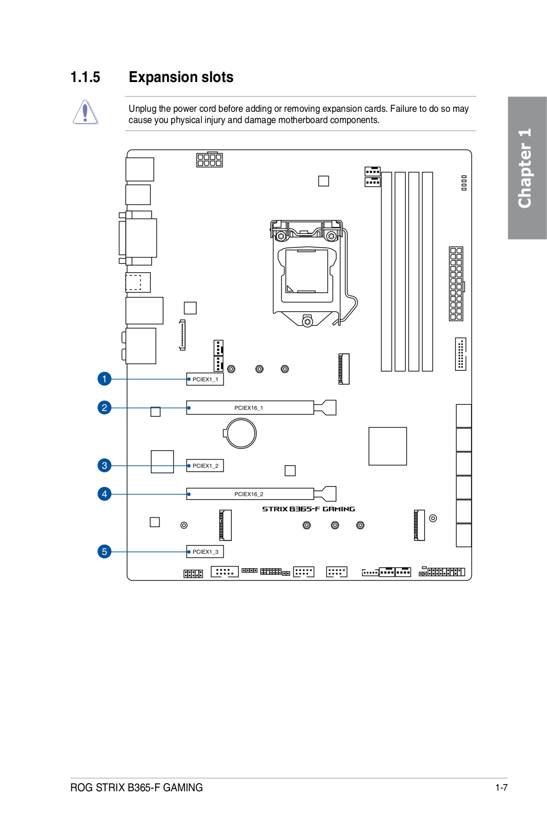
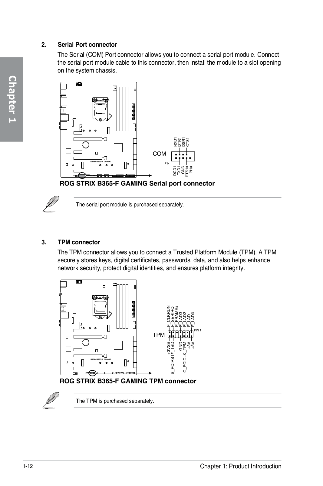
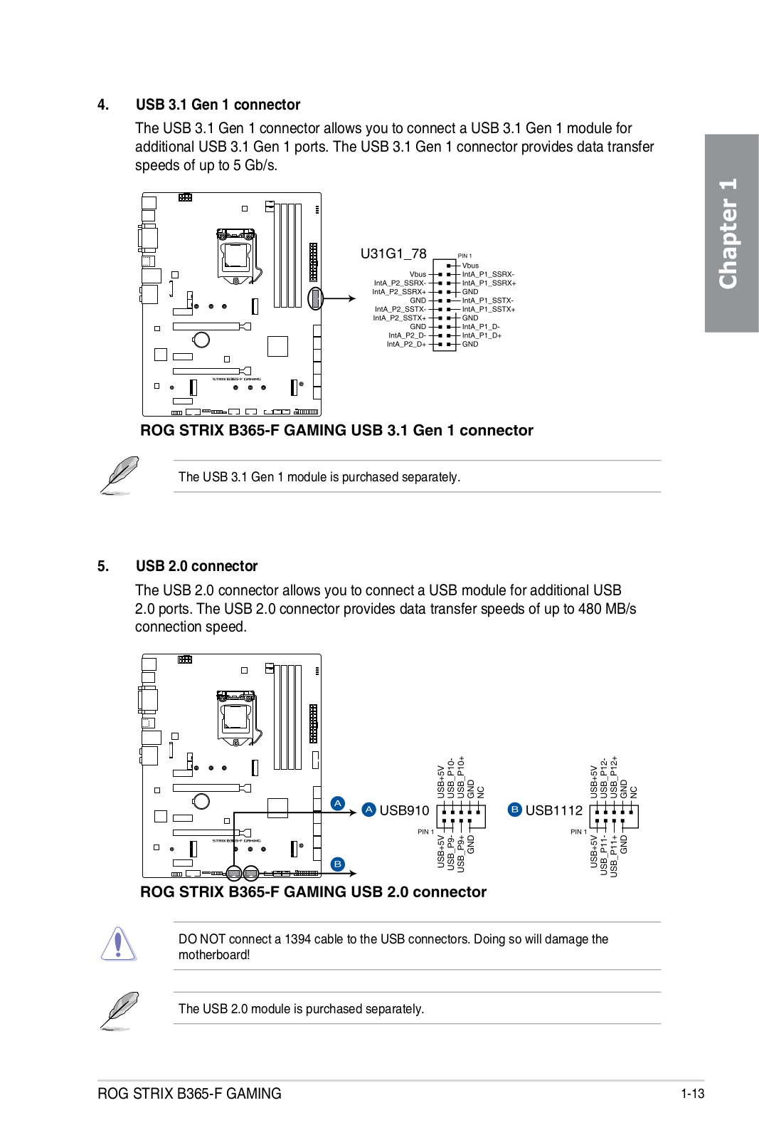
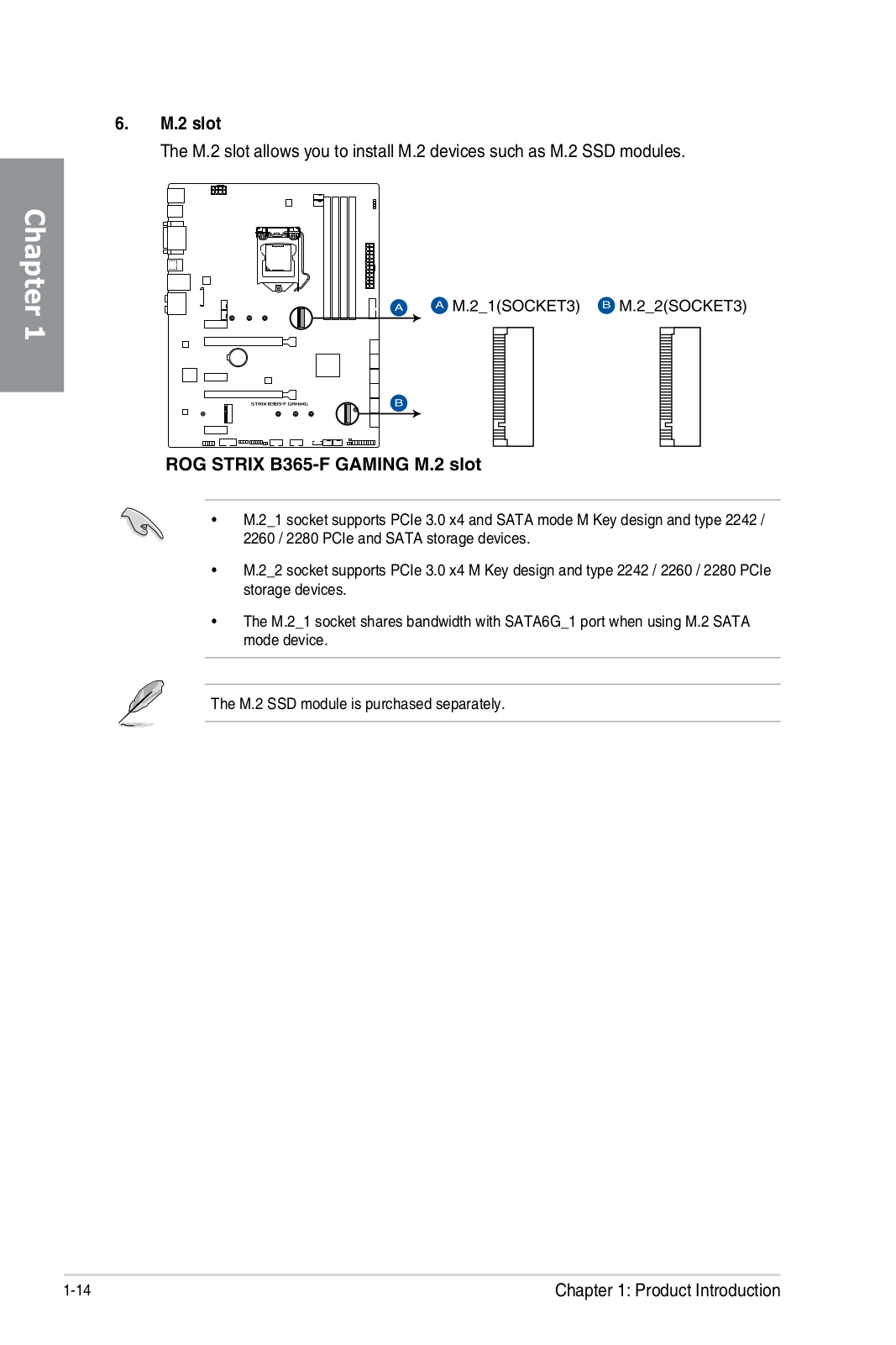
ROG Strix B365-F Gaming
Service Manual
92 pgs
6.58 Mb
0
Table of contents
Loading...
ASUS ROG Strix B365-F Gaming Service Manual
...
ASUS Service Manual
Download
Specifications and Main Features
Frequently Asked Questions
User Manual
Download
Loading...
+
64
hidden pages
Unhide
You need points to download manuals.
1 point = 1 manual.
You can buy points or you can get point for every manual you upload.
Buy points
Upload your manuals
 Loading...