

Page 1
Pundit P3-PH4/P3-PH5
ASUS PC (Desktop Barebone)
Installation Manual
English
Download the latest manual from the ASUS website: www.asus.com
Page 2
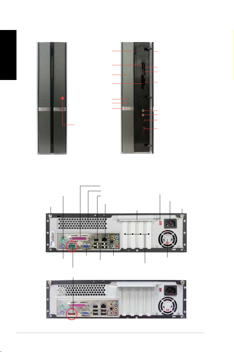
Front panel features
English
Close Open
Optical drive
eject button
Memory Stick®/
Pro™card slot
Optical drive bay cover
CompactFlash®
card slot
HDD LED
Power LED
Power button
Press to open the
front panel cover
Rear panel features
Parallel port
PS/2 mouse port
Cover screw
Air vents
IEEE 1394a port
LAN (RJ-45) port
Metal bracket lock
Front panel cover
SmartMedia® card slot
Card reader LED
Secure Digital™/
MultimediaCard slot
Headphone port
Microphone port
IEEE 1394a port
USB 2.0 ports
Voltage selector
Power connector
Cover screw
PS/2 keyboard port
Serial port (for P3-PH4 model)
ESATA port (for P3-PH5 model)
VGA port
8-channel audio ports
USB 2.0 ports
2 Installation Manual
PCI slot metal brackets
Power fan vents
Page 3
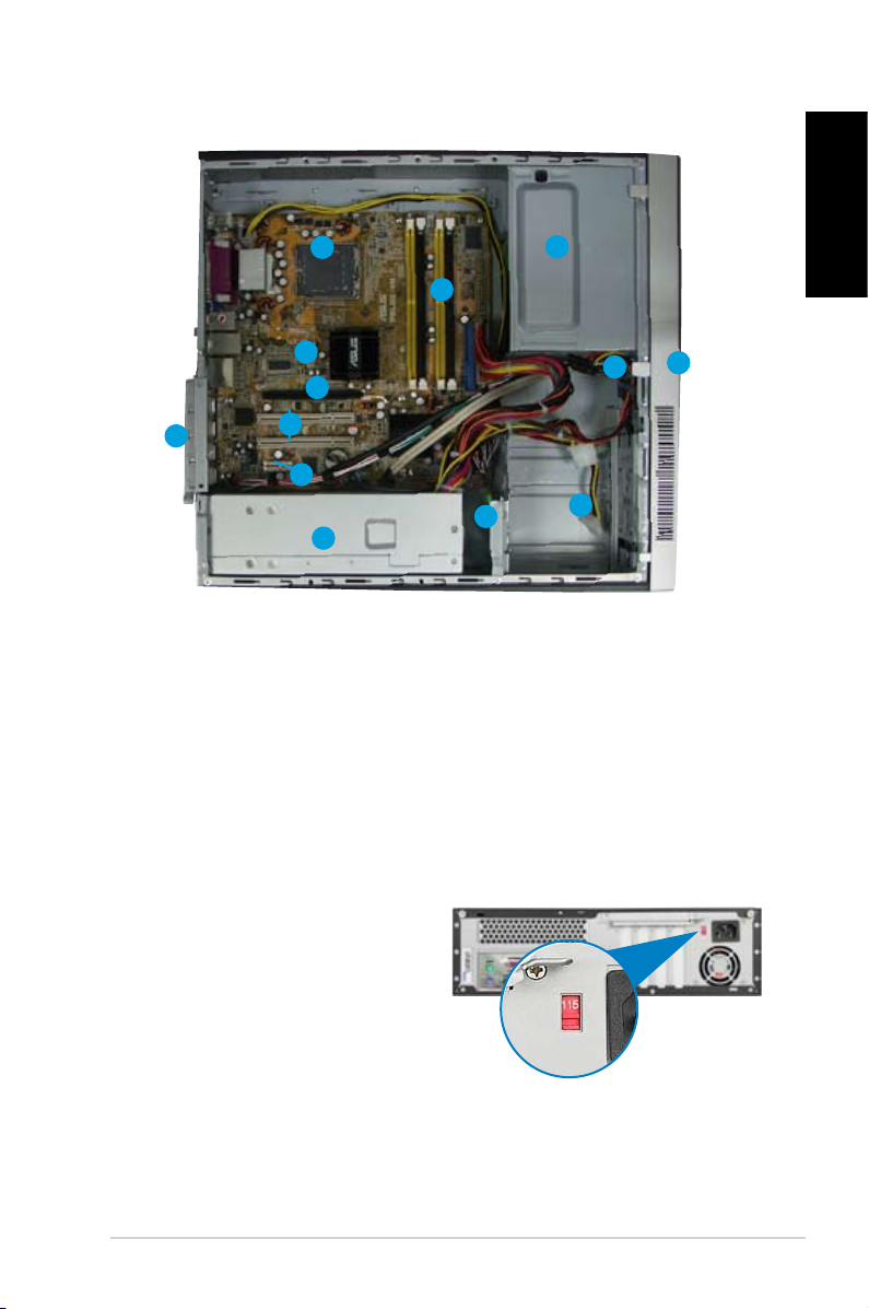
Internal components
12
10
9
11
8
7
6
1. 5.25-inch empty optical drive bay
2. Front panel cover
3. Optical drive lock
4. Hard disk drive bays
5. Hard disk drive lock
6. Power supply unit
Selecting the voltage
The system’s power supply unit has
a 115 V/230 V voltage selector switch
located beside the power connector.
Use this switch to select the appropriate
system input voltage according to the
voltage supply in your area.
If the voltage supply in your area is
100-127 V, set the switch to 115 V.
If the voltage supply in your area is
200-240 V, set the switch to 230 V.
1
13
3
5
4
7. PCI Express x1 slot
8. PCI slots
9. PCI Express x16 slot
10. ASUS motherboard
11. Metal bracket lock
12. LGA775 socket
13. DIMM sockets
English
2
3Installation Manual
Page 4

Removing the cover
English
1. Locate two cover screws.
3. Pull the cover.
5. Lift the expansion card lock to a
90º-100º angle.
2. Remove the cover screws.
4. Lift the cover, then set aside.
6. Lift the chassis support bracket,
then remove.
Removing the front panel assembly
1. Locate the front panel
assembly hooks.
2. Pull the hooks
outward to remove.
4 Installation Manual
Page 5

Installing a CPU
1. Locate the CPU socket. 2. Unlock the load lever.
A
Load leverRetention tab
English
B
3. Lift the load lever.
5. Carefully push the PnP cap from
the load plate window to remove.
A
4. Lift the load plate.
6. Install the CPU, noting the
position of the gold triangle as
shown.
5Installation Manual
Page 6

English
Installing the CPU fan and heatsink assembly
8. Lock the load lever.7. Close the load plate.
1. Place the heatsink on top of the
installed CPU.
2. Drive four screws into the fan
holes to secure the fan to the
motherboard.
Installing a DIMM
1. Locate the DIMM sockets in the
motherboard.
2. Unlock a DIMM socket by
pressing the retaining clips
outward.
3. Align a DIMM on the socket
such that the notch on the DIMM
matches the break on the socket.
3. Connect the CPU fan cable.
2
1
DDR2 DIMM notch
1
6 Installation Manual
Page 7

Installing an expansion card
1. Remove the metal cover opposite
the slot that you intend to use.
2. Insert the card connector to the
slot, then press the card rmly
until it ts in place.
Installing an optical drive
1. Drive a screw on the top right
screw hole on both sides of the
drive.
3. Push the drive all the way into the
bay until the drive lock clicks.
4. Connect a 4-pin power plug from
the power supply unit to the power
connector at the back of the drive.
2. Connect the IDE and audio cable
at the back of the drive.
English
Installing a SATA hard disk drive
1. Drive two screws with rubber
washers on both sides of the
drive.
Power cable
and plug
Signal cable
and plug
Rubber washer
2. Connect the SATA signal and
power plug at the back of the
drive.
7Installation Manual
Page 8

English
3. Place the HDD on the tray. 4. When the HDD screws align,
push the drive on the bay.
HDD screw lock
Replacing the covers
1. Replace the front panel assembly.
2. Reinstall the metal chassis
support and the expansion card
lock.
3. Insert the cover hooks to the
holes on the chassis side.
8 Installation Manual
4. Push the cover to the direction of
the front panel, then replace the
cover screws.
 Loading...