

Page 1
Pundit P3-PH4
Barebone System
Quick Installation Guide
Page 2
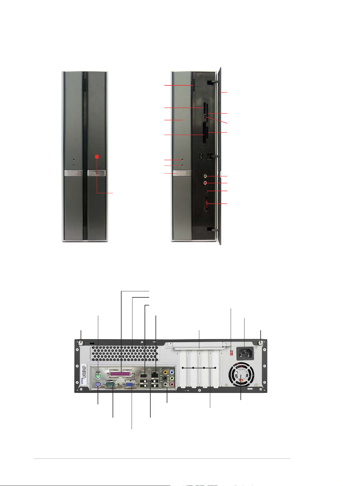
Front panel features
CloseClose
Close
CloseClose
Optical driveOptical drive
Optical drive
Optical driveOptical drive
eject buttoneject button
eject button
eject buttoneject button
®®
®
Memory StickMemory Stick
Memory Stick
Memory StickMemory Stick
Pro™ card slotPro™ card slot
Pro™ card slot
Pro™ card slotPro™ card slot
Optical driveOptical drive
Optical drive
Optical driveOptical drive
bay coverbay cover
bay cover
bay coverbay cover
CompactFlashCompactFlash
CompactFlash
CompactFlashCompactFlash
card slotcard slot
card slot
card slotcard slot
HDD LEDHDD LED
HDD LED
HDD LEDHDD LED
Power LEDPower LED
Power LED
Power LEDPower LED
Power buttonPower button
Power button
Power buttonPower button
PressPress
to open to open
Press
to open
PressPress
to open to open
the front the front
the front
the front the front
covercover
cover
covercover
®®
panelpanel
panel
panelpanel
OpenOpen
Open
OpenOpen
Front panel coverFront panel cover
Front panel cover
Front panel coverFront panel cover
//
/
//
SmartMediaSmartMedia
SmartMedia
SmartMediaSmartMedia
Card reader LEDCard reader LED
Card reader LED
Card reader LEDCard reader LED
Secure Digital™/Secure Digital™/
Secure Digital™/
®®
®
®®
Secure Digital™/Secure Digital™/
MultimediaCard slotMultimediaCard slot
MultimediaCard slot
MultimediaCard slotMultimediaCard slot
Headphone portHeadphone port
Headphone port
Headphone portHeadphone port
Microphone portMicrophone port
Microphone port
Microphone portMicrophone port
IEEE 1394a portIEEE 1394a port
IEEE 1394a port
IEEE 1394a portIEEE 1394a port
USB 2.0 portsUSB 2.0 ports
USB 2.0 ports
USB 2.0 portsUSB 2.0 ports
®®
®
®®
card slot card slot
card slot
card slot card slot
Rear panel features
Parallel portParallel port
Parallel port
Parallel portParallel port
Air ventsAir vents
Air vents
Air ventsAir vents
IEEE 1394a portIEEE 1394a port
IEEE 1394a port
IEEE 1394a portIEEE 1394a port
LAN (RJ-45) portLAN (RJ-45) port
PS/2 mouse portPS/2 mouse port
PS/2 mouse port
PS/2 mouse portPS/2 mouse port
Cover screwCover screw
Cover screw
Cover screwCover screw
PS/2 keyboard portPS/2 keyboard port
PS/2 keyboard port
PS/2 keyboard portPS/2 keyboard port
Serial portSerial port
Serial port
Serial portSerial port
USB 2.0 portsUSB 2.0 ports
USB 2.0 ports
USB 2.0 portsUSB 2.0 ports
VGA portVGA port
VGA port
VGA portVGA port
LAN (RJ-45) port
LAN (RJ-45) portLAN (RJ-45) port
audio portsaudio ports
audio ports
audio portsaudio ports
Metal bracket lockMetal bracket lock
Metal bracket lock
Metal bracket lockMetal bracket lock
8-channel8-channel
8-channel
8-channel8-channel
PCI slot metal bracketsPCI slot metal brackets
PCI slot metal brackets
PCI slot metal bracketsPCI slot metal brackets
Voltage selectorVoltage selector
Voltage selector
Voltage selectorVoltage selector
Power connectorPower connector
Power connector
Power connectorPower connector
Cover screwCover screw
Cover screw
Cover screwCover screw
Power fan ventsPower fan vents
Power fan vents
Power fan ventsPower fan vents
22
2
22
Quick Installation GuideQuick Installation Guide
Quick Installation Guide
Quick Installation GuideQuick Installation Guide
Page 3
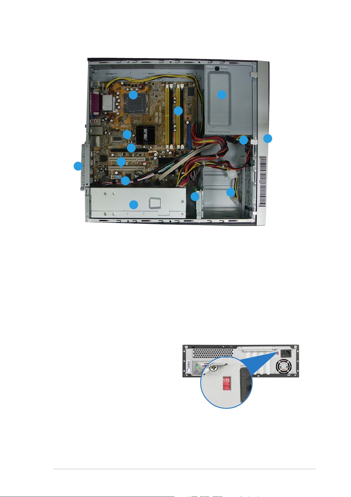
Internal components
1212
12
1212
11
1
11
1010
10
1010
99
9
99
88
8
11
11
1
1
11
11
88
77
7
77
66
6
66
11
1
11
33
3
33
22
2
33
3
33
44
4
55
5
55
44
22
1. 5.25-inch empty optical drive bay
2. Front panel cover
3. Optical drive lock
4. Hard disk drive bays
5. Hard disk drive lock
6. Power supply unit
Selecting the voltage
The system’s power supply unit has
a 115 V/230 V voltage selector
switch located beside the power
connector. Use this switch to select
the appropriate system input voltage
according to the voltage supply in
your area.
7. PCI Express x1 slot
8. PCI slots
9. PCI Express x16 slot
10. ASUS motherboard
11. Metal bracket lock
12. LGA775 socket
13. DIMM sockets
If the voltage supply in your area is
100-127 V, set the switch to 115 V.
If the voltage supply in your area is
200-240 V, set the switch to 230 V.
Quick Installation GuideQuick Installation Guide
Quick Installation Guide
Quick Installation GuideQuick Installation Guide
33
3
33
Page 4

Removing the cover
1. Locate two cover screws.
3. Pull the cover.
2. Remove the cover screws.
4. Lift the cover, then set aside.
5. Lift the expansion card lock to
a 90º-100º angle.
6. Lift the chassis support
bracket, then remove.
Removing the front panel assembly
1. Locate the front
panel assembly
hooks.
2. Pull the hooks
outward to remove.
44
4
44
Quick Installation GuideQuick Installation Guide
Quick Installation Guide
Quick Installation GuideQuick Installation Guide
Page 5

Installing a CPU
1. Locate the CPU socket. 2. Unlock the load lever.
AA
A
AA
BB
B
BB
Retention tabRetention tab
Retention tab
Retention tabRetention tab
Load leverLoad lever
Load lever
Load leverLoad lever
3. Lift the load lever. 4. Lift the load plate.
5. Carefully push the PnP cap
from the load plate window to
remove.
6. Install the CPU, noting the
position of the gold triangle as
shown.
AA
A
AA
Quick Installation GuideQuick Installation Guide
Quick Installation Guide
Quick Installation GuideQuick Installation Guide
55
5
55
Page 6

8. Lock the load lever.7. Close the load plate.
Installing the CPU fan and heatsink assembly
1. Place the heatsink on top of
the installed CPU.
2. Drive four screws into the fan
holes to secure the fan to the
motherboard.
Installing a DIMM
3. Connect the CPU fan cable.
1. Locate the DIMM sockets in
the motherboard.
2. Unlock a DIMM socket by
pressing the retaining clips
outward.
3. Align a DIMM on the socket
such that the notch on the
DIMM matches the break on
the socket.
66
6
66
DDR2 DIMM notchDDR2 DIMM notch
DDR2 DIMM notch
1
Quick Installation GuideQuick Installation Guide
Quick Installation Guide
Quick Installation GuideQuick Installation Guide
DDR2 DIMM notchDDR2 DIMM notch
2
1
Page 7

Installing an expansion card
1. Remove the metal cover
opposite the slot that you
intend to use.
2. Insert the card connector to
the slot, then press the card
firmly until it fits in place.
Installing an optical drive
1. Drive a screw on the top right
screw hole on both sides of
the drive.
2. Connect the IDE and audio
cable at the back of the drive.
3. Push the drive all the way into
the bay until the drive lock clicks.
4. Connect a 4-pin power plug
from the power supply unit to
the power connector at the
back of the drive.
Installing a SATA hard disk drive
1. Drive two screws with rubber
washers on both sides of the
drive.
Power cablePower cable
Power cable
Power cablePower cable
and plugand plug
and plug
and plugand plug
Signal cableSignal cable
Signal cable
Signal cableSignal cable
and plugand plug
and plug
and plugand plug
2. Connect the SATA signal and
power plug at the back of the
drive.
Rubber washerRubber washer
Rubber washer
Rubber washerRubber washer
Quick Installation GuideQuick Installation Guide
Quick Installation Guide
Quick Installation GuideQuick Installation Guide
77
7
77
Page 8

3. Place the HDD on the tray. 4. When the HDD screws align,
push the drive on the bay.
HDD screw lockHDD screw lock
HDD screw lock
HDD screw lockHDD screw lock
Replacing the covers
1. Replace the front panel
assembly.
3. Insert the cover hooks to the
holes on the chassis side.
2. Reinstall the metal chassis
support and the expansion
card lock.
4. Push the cover to the direction
of the front panel, then
replace the cover screws.
88
8
88
Quick Installation GuideQuick Installation Guide
Quick Installation Guide
Quick Installation GuideQuick Installation Guide
 Loading...