


ASUS PUNDIT P3-PE5 User Guide
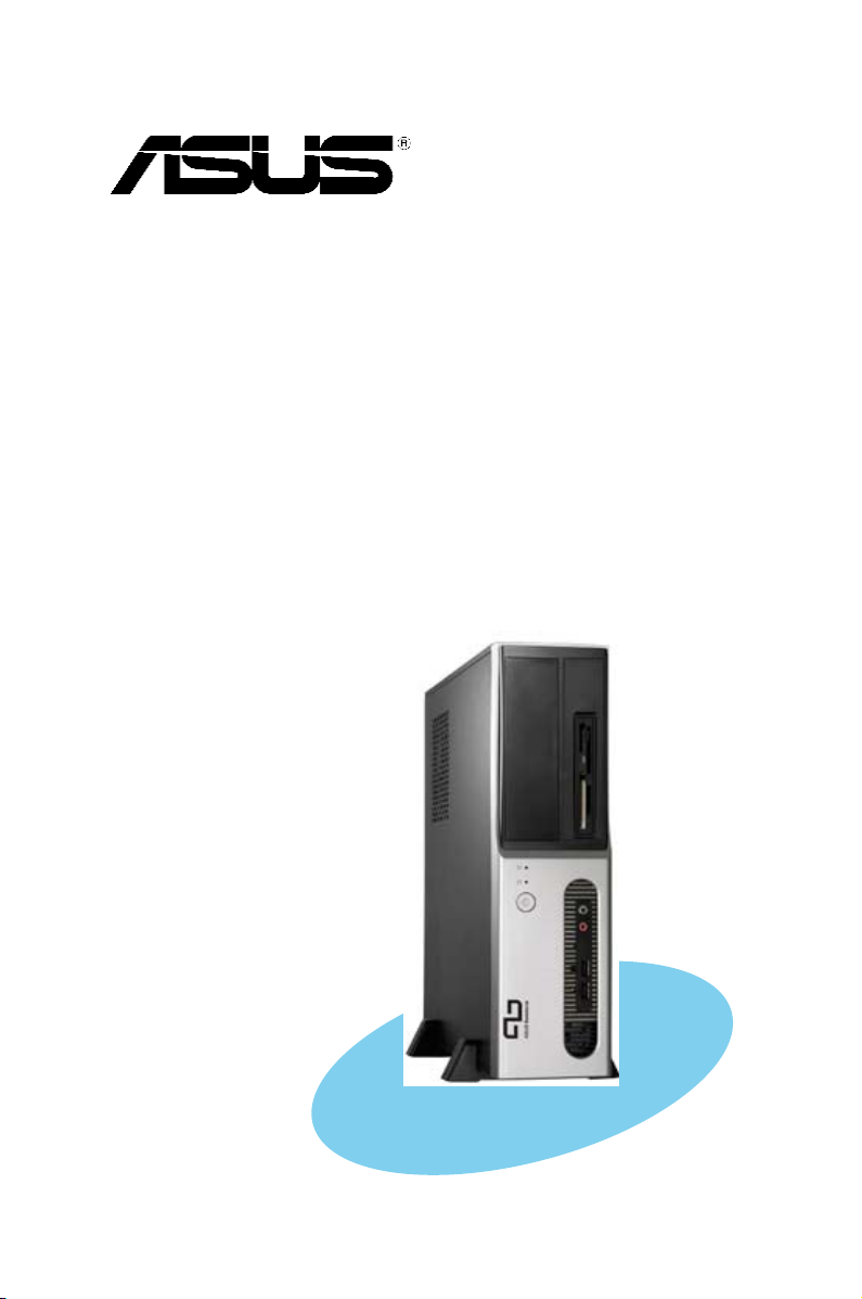
Pundit P3-PE5
ASUS PC (Desktop Barebone)
E300 7
Firs t E diti o n V1
Octo b e r 200 6
Copyright © 2006 ASUSTeK COMPUTER INC. All Rights Reserved.
No part of this manual, including the products and software described in it, may be reproduced,
transmitted, transcribed, stored in a retrieval system, or translated into any language in any form
or by any means, except documentation kept by the purchaser for backup purposes, without the
express written permission of ASUSTeK COMPUTER INC. (“ASUS”).
Product warranty or service will not be extended if: (1) the product is repaired, modied or
altered, unless such repair, modication of alteration is authorized in writing by ASUS; or (2) the
serial number of the product is defaced or missing.
ASUS PROVIDES THIS MANUAL “AS IS” WITHOUT WARRANTY OF ANY KIND, EITHER EXPRESS
OR IMPLIED, INCLUDING BUT NOT LIMITED TO THE IMPLIED WARRANTIES OR CONDITIONS OF
MERCHANTABILITY OR FITNESS FOR A PARTICULAR PURPOSE. IN NO EVENT SHALL ASUS,
ITS DIRECTORS, OFFICERS, EMPLOYEES OR AGENTS BE LIABLE FOR ANY INDIRECT, SPECIAL,
INCIDENTAL, OR CONSEQUENTIAL DAMAGES (INCLUDING DAMAGES FOR LOSS OF PROFITS, LOSS
OF BUSINESS, LOSS OF USE OR DATA, INTERRUPTION OF BUSINESS AND THE LIKE), EVEN IF ASUS
HAS BEEN ADVISED OF THE POSSIBILITY OF SUCH DAMAGES ARISING FROM ANY DEFECT OR
ERROR IN THIS MANUAL OR PRODUCT.
SPECIFICATIONS AND INFORMATION CONTAINED IN THIS MANUAL ARE FURNISHED FOR
INFORMATIONAL USE ONLY, AND ARE SUBJECT TO CHANGE AT ANY TIME WITHOUT NOTICE, AND
SHOULD NOT BE CONSTRUED AS A COMMITMENT BY ASUS. ASUS ASSUMES NO RESPONSIBILITY
OR LIABILITY FOR ANY ERRORS OR INACCURACIES THAT MAY APPEAR IN THIS MANUAL,
INCLUDING THE PRODUCTS AND SOFTWARE DESCRIBED IN IT.
Products and corporate names appearing in this manual may or may not be registered
trademarks or copyrights of their respective companies, and are used only for identication or
explanation and to the owners’ benet, without intent to infringe.
ii
Table of contents
Notices ................................................................................................ vi
Safety information ..............................................................................vii
About this guide .................................................................................viii
System package contents .................................................................... x
Cha p te r 1 : S y ste m I n tro d uc t ion
1.1 Welcome! .............................................................................. 1-2
1.2 Front panel ............................................................................
1.3 Rear panel .............................................................................
1.4 Internal components .............................................................
Cha p te r 2 : Bas i c I nst a ll a tio n
2.1 Preparation ........................................................................... 2-2
2.2 Before you proceed ..............................................................
2.3 Removing the cover and front panel assembly .....................
2.4 Central Processing Unit (CPU) ..............................................
2.4.1 Overview .................................................................
2.4.2 Installing CPU ..........................................................
2.4.3 Installing the CPU fan and heatsink assembly .........
2.5 Installing a DIMM ...................................................................
2.5.1 Memory congurations ...........................................
2.5.2 Installing a DDR2 DIMM ...........................................
2.5.3 Removing a DDR2 DIMM ..........................................
2.6 Expansion slots ...................................................................
2.6.1 Installing an expansion card ..................................
2.6.2 Conguring an expansion card ..............................
2.6.3 PCI Express x 1 slot ..............................................
2.6.4 PCI slots ................................................................
2.6.5 PCI Express x 16 slot ............................................
2.7 Installing an optical drive ....................................................
2.8 Removing the card reader
2.9 Installing hard disk drivers (HDDs) ......................................
2.9.1 Hard disk drive bays ..............................................
2.9.2 SATA hard disk drive installation ..........................
2.9.3 IDE hard disk drive installation ..............................
2.9.4 Uninstalling a hard disk drive ................................
................................................... 2-15
1-2
1-4
1-6
2-2
2-3
2-4
2-4
2-4
2-6
2-7
2-7
2-9
2-9
2-10
2-10
2-10
2-12
2-12
2-12
2-13
2-16
2-16
2-16
2-16
2-16
iii

Table of contents
2.10 Replacing the covers ........................................................... 2-19
2.10.1 Replacing the front panel assembly ......................
2.10.2 Replacing the system cover ..................................
2.11 Installing the foot stands ....................................................
Cha p te r 3 : Sta r ti n g u p
3.1 Installing an operating system .............................................. 3-2
3.2 Powering up ..........................................................................
3.3 Support CD information ........................................................
3.3.1 Running the support CD ..........................................
3.3.2 Utilities menu ..........................................................
3.3.3 Make Disk ................................................................
3.3.4 ASUS contact information ......................................
3.4 Software information ............................................................
Cha p te r 4 : Mot h er b oar d I n fo
4.1 Introduction .......................................................................... 4-2
4.2 Motherboard layout ..............................................................
4.3 Jumpers ................................................................................
4.4 Connectors ...........................................................................
2-19
2-20
2-21
3-2
3-2
3-3
3-4
3-5
3-5
3-6
4-2
4-3
4-6
Cha p te r 5 : BIO S I n for m at i on
5.1 Managing and updating your BIOS ........................................ 5-2
5.1.1 ASUS Update utility ................................................
5.1.2 Creating a bootable oppy disk ..............................
5.1.3 ASUS EZ Falsh .........................................................
5.1.4 AwardBIOS Flsh Utility .............................................
5.1.5 Saving the current BIOS le ....................................
5.1.6 ASUS CrashFree BIOS 2 utility ..............................
5.2 BIOS setup program ............................................................
5.2.1 BIOS menu screen .................................................
5.2.2 Menu bar ...............................................................
5.2.3 Legend bar ............................................................
iv
5-2
5-5
5-6
5-7
5-9
5-10
5-11
5-12
5-12
5-13

Table of contents
5.2.4 Menu items ........................................................... 5-13
5.2.5 Sub-menu items ....................................................
5.2.6 Conguration elds ...............................................
5.2.7 Pop-up window ......................................................
5.2.8 General help ..........................................................
5.3 Main menu ...........................................................................
5.3.1 System Time ........................................................
5.3.2 System Date ........................................................
5.3.3 Primary IDE Master/Slave ......................................
5.3.4 First/Second SATA Master ...................................
5.3.5 HDD SMART Monitoring .........................................
5.4 Advanced menu ..................................................................
5.4.1 CPU Condiguration ................................................
5.4.2 Chipset ..................................................................
5.4.3 PCIPnP ...................................................................
5.4.4 Onboard Device Conguration ..............................
5.4.5 USB Conguration .................................................
5.5 Power menu ........................................................................
5.5.1 ACPI Suspend Type ...............................................
5.5.2 ACPI APIC Support ................................................
5.5.3 APM Conguration ................................................
5.5.4 Hardware Monitor ..................................................
5.6 Boot menu ..........................................................................
5.6.1 Boot Device Priority ..............................................
5.6.2 Hard Disk Drives ....................................................
5.6.3 Boot Settings Conguration .................................
5.6.4 Security .................................................................
5.7 Exit menu ............................................................................
5-13
5-13
5-14
5-14
5-15
5-15
5-15
5-16
5-18
5-19
5-19
5-20
5-21
5-23
5-24
5-25
5-26
5-26
5-26
5-27
5-29
5-31
5-31
5-31
5-32
5-33
5-34
v
Notices
Fed er al Co mm un ica ti on s C om mi ssi on S tat em en t
This device complies with Part 15 of the FCC Rules. Operation is subject to
the following two conditions:
•
This device may not cause harmful interference, and
•
This device must accept any interference received including
interference that may cause undesired operation.
This equipment has been tested and found to comply with the limits for a
Class B digital device, pursuant to Part 15 of the FCC Rules. These limits
are designed to provide reasonable protection against harmful interference
in a residential installation. This equipment generates, uses and can radiate
radio frequency energy and, if not installed and used in accordance with
manufacturer’s instructions, may cause harmful interference to radio
communications. However, there is no guarantee that interference will
not occur in a particular installation. If this equipment does cause harmful
interference to radio or television reception, which can be determined by
turning the equipment off and on, the user is encouraged to try to correct
the interference by one or more of the following measures:
•
Reorient or relocate the receiving antenna.
•
Increase the separation between the equipment and receiver.
•
Connect the equipment to an outlet on a circuit different from that to
which the receiver is connected.
•
Consult the dealer or an experienced radio/TV technician for help.
WARNING! The use of shielded cables for connection of the monitor to
the graphics card is required to assure compliance with FCC regulations.
Changes or modications to this unit not expressly approved by the
party responsible for compliance could void the user’s authority to
operate this equipment.
Can ad ia n D ep ar tme nt o f C om mu nic at io ns St at eme nt
This digital apparatus does not exceed the Class B limits for radio noise
emissions from digital apparatus set out in the Radio Interference
Regulations of the Canadian Department of Communications.
This class B digital apparatus complies with Canadian ICES-003.
vi
Safety information
Ele ct ri cal s af ety
•
To prevent electrical shock hazard, disconnect the power cable from
the electrical outlet before relocating the system.
•
When adding or removing devices to or from the system, ensure that
the power cables for the devices are unplugged before the signal cables
are connected.
•
If the power supply is broken, do not try to fix it by yourself. Contact a
qualified service technician or your retailer.
Ope ra ti on sa fe ty
•
Before installing devices into the system, carefully read all the
documentation that came with the package.
•
Before using the product, make sure all cables are correctly connected
and the power cables are not damaged. If you detect any damage,
contact your dealer immediately.
•
To avoid short circuits, keep paper clips, screws, and staples away from
connectors, slots, sockets and circuitry.
•
Avoid dust, humidity, and temperature extremes. Do not place the
product in any area where it may become wet. Place the product on a
stable surface.
•
If you encounter technical problems with the product, contact a
qualified service technician or your retailer.
Lithium-Ion Battery Warning
CAUTION: Danger of explosion if battery is incorrectly replaced.
Replace only with the same or equivalent type recommended by
the manufacturer. Dispose of used batteries according to the
manufacturer’s instructions.
VORSICHT: Explosionsgetahr bei unsachgemäßen Austausch der
Batterie. Ersatz nur durch denselben oder einem vom Hersteller
empfohlenem ähnljchen Typ. Entsorgung gebrauchter Batterien nach
Angaben des Herstellers.
LASER PRODUCT WARNING
CLA SS 1 LA SE R PRO DU CT
vii
About this guide
Aud ie nc e
This guide provides general information and installation instructions about
the ASUS Pundit P3 - PE5 barebone system. This guide is intended for
experienced users and integrators with hardware knowledge of personal
computers.
How t hi s g ui de is o rg ani ze d
This guide contains the following parts:
1. Chap t e r 1: S y s tem i n t rodu c t i on
This chapter gives a general description of the ASUS
Pundit P3 - PE5. The chapter lists the system features, including
introduction on the front and rear panel, and internal components.
2. Chap t e r 2: B a s ic i n s t alla t i o n
This chapter provides step-by-step instructions on how to install
components in the system.
3. Chap t e r 3: S t a rtin g u p
This chapter helps you power up the system and install drivers and
utilities from the support CD.
4. Chap t e r 4: M o t herb o a r d in f o r mati o n
This chapter gives information about the motherboard that comes
with the system. This chapter includes the motherboard layout,
jumper settings, and connector locations.
5. Chap t e r 5: B I O S in f o r mati o n
This chapter tells how to change system settings through the BIOS
Setup menus and describes the BIOS parameters.
viii
Con ve nt ion s us ed in t his g ui de
WARNING: Information to prevent injury to yourself when trying
to complete a task.
CAUTION: Information to prevent damage to the components
when trying to complete a task.
IMPORTANT: Instructions that you MUST follow to complete a
task.
NOTE: Tips and additional information to aid in completing a
task.
Whe re t o f in d mor e in for ma ti on
Refer to the following sources for additional information and for product
and software updates.
1. ASUS W e bsit e s
The ASUS websites worldwide provide updated information on
ASUS hardware and software products. Refer to the ASUS contact
information.
2. Opti o n a l Do c u m enta t i o n
Your product package may include optional documentation, such as
warranty yers, that may have been added by your dealer. These
documents are not part of the standard package.
ix
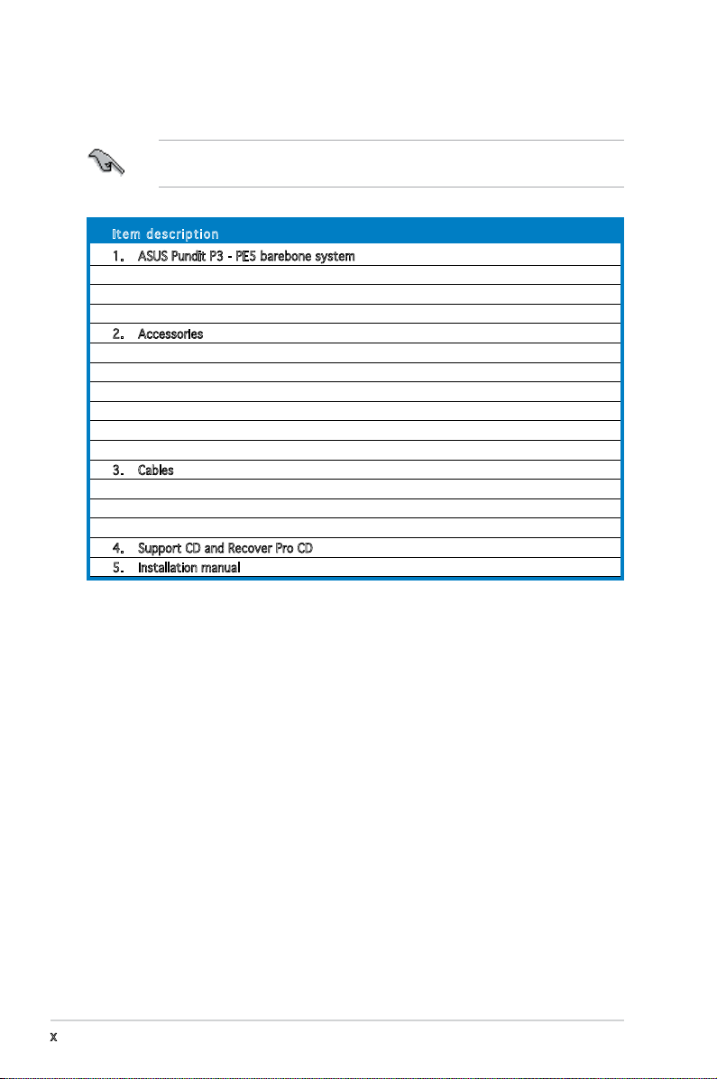
System package contents
Check your Pundit P3 - PE5 system package for the following items.
If any of the items is damaged or missing, contact your retailer
immediately.
Ite m d escri p t i on
1. ASUS Pundit P3 - PE5 barebone system with
• ASUS motherboard
• 275 W PFC power supply unit
• 6-in-1 storage card reader
2. Accessories
• CPU fan and heatsink assembly
• Foot stand and screw (1 pair) for vertical placement
• Rubber stand (x 4) for horizontal placement
• Hard disk drive screw (x 8)
• Optical drive screw (x 2)
• Rubber washer (x 8)
3. Cables
• AC power cable
• Serial ATA signal cable (x 2)
• IDE cable (x 2)
4. Support CD and Recover Pro CD
5. Installation manual
x
Chapter 1
This chapter gives a general
description of the ASUS
Pundit P3-PE5. The chapter lists
the system features including
introduction on the front and rear
panel, and internal components.
ASUS Pundit P3-PE5
System introduction
1.1 Welcome!
Thank you for choosing the ASUS Pundit P3-PE5!
The ASUS Pundit P3-PE5 is an all-in-one barebone system with a versatile
home entertainment feature.
The system comes in a stylish mini-tower casing and powered by the ASUS
motherboard that supports the Intel® Pentium® D, Intel® Pentium® 4 or
Intel® Celeron® processor in the 775-land package.
The system supports up to 2 GB of system memory using
DDR2-533/400 DIMMs, high-resolution graphics via integrated graphics
controller or PCI Express x16 slot, Serial ATA, USB 2.0, and
6-channel audio features the system takes you ahead in the world of power
computing.
1.2 Front panel
The front panel includes the optical drive bays, power button, and several
I/O ports are located at the front panel.
4
1
3
5
1-2 Chapter 1: System introduction
7
6
11
12
2
8
10
9
13
1. HDD LED. This LED lights up when data is read from or written to the
hard disk drive.
2. 5.25-inch bay. This bay is for an IDE optical drive.
3. Power button. Press this button to turn the system on.
4. Power LED.
5. USB 2.0 ports. These Universal Serial Bus 2.0 (USB 2.0) ports are
available for connecting USB 2.0 devices such as a mouse, printer,
scanner, camera, PDA, and others.
6. Microphone port. This Mic (pink) port connects a microphone.
7. Headphone port. This Line In (green) port connects a headphone with
a stereo mini-plug.
8. 6- in1 card reader.
9. Memory Stick/Pro
TM
Card slot.
10. Card reader LED.
11. CompactFlashTM Card slot.
12. Secure DigitalTM /MultimediaCard slot.
13. SmartMediaTM card slot.
1-3ASUS Pundit P3-PE5
1.3 Rear panel
The system rear panel includes the power connector and several I/O ports
that allow convenient connection of devices.
3
2
1
12
11
5
4
6
14
13 15
7
8
10
9
1816 17
1. Cover screw.
2. PS/2 mouse port. This green 6-pin connector is for a PS/2 mouse.
3. Parallel port. This 25-pin port connects a printer, scanner, or other
devices.
4. Air vents.
5. USB 2.0 ports 1, 2, 3 and 4. These 4-pin Universal Serial Bus (USB)
ports are available for connecting USB 2.0 devices.
6. LAN (RJ-45) port. This port allows Gigabit connection to a Local Area
Network (LAN) through a network hub.
7. Metal bracket lock.
8. Voltage selector. This switch allows you to adjust the system input
voltage according to the voltage supply in your area. If the voltage
supply in your area is 100-127V, set this switch to 115V. If the
voltage supply in your area is 200-240V, set this switch to 230V.
9. Power connector. This connector is for the power cable and plug.
10. Cover screw.
WARNING! Setting the switch to 115V in a 230V environment or 230V
in a 115 environment will seriously damage the system!
1-4 Chapter 1: System introduction
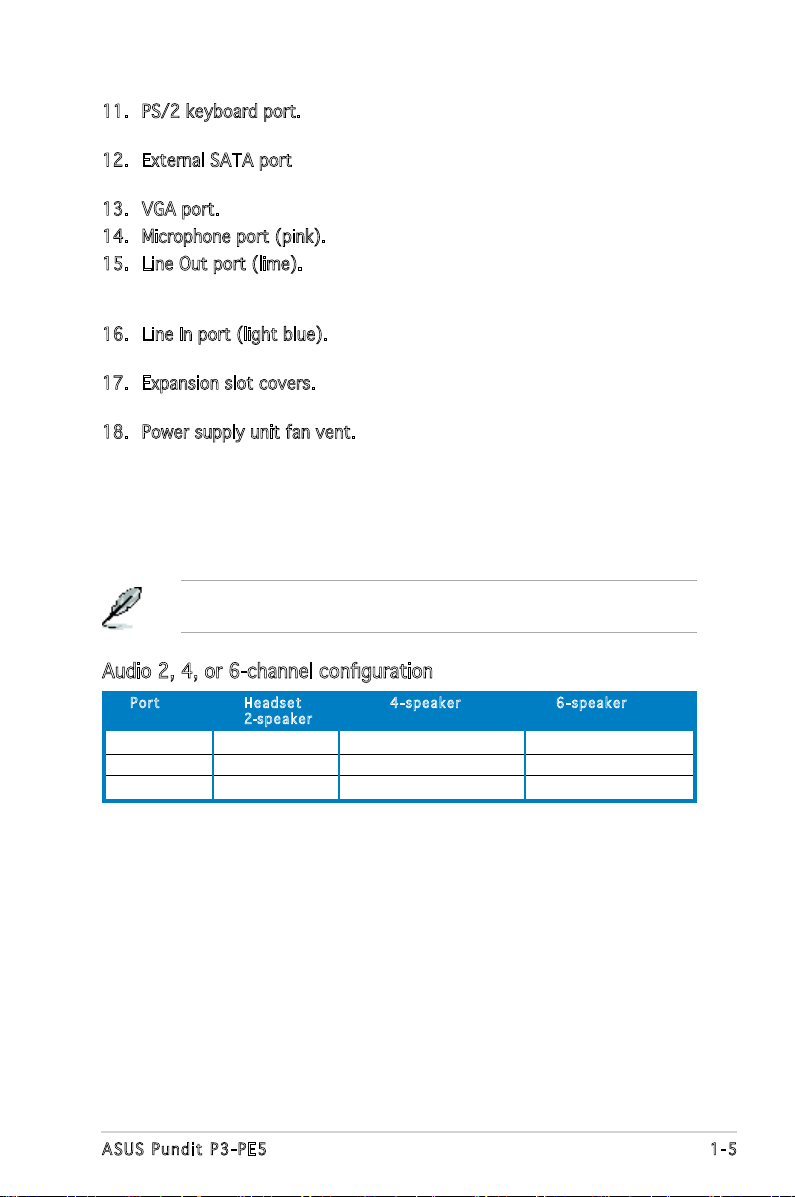
11. PS/2 keyboard port. This purple 6-pin connector is for a
PS/2 keyboard.
12. External SATA port. This port connects to an external SATA box or a
Serial ATA port multiplier.
13. VGA port. This port connects a VGA monitor.
14. Microphone port (pink). This port connects a microphone.
15. Line Out port (lime). This port connects a headphone or a speaker.
In 4-channel and 6-channel conguration, the function of this port
becomes Front Speaker Out.
16. Line In port (light blue). This port connects the tape, CD, DVD player,
or other audio sources.
17. Expansion slot covers. Remove these covers when installing expansion
cards.
18. Power supply unit fan vent. This vent is for the PSU fan that provides
ventilation inside the power supply unit.
Refer to the audio conguration table below for the function of the audio
ports in 2, 4, or 6-channel conguration.
Audio 2, 4, or 6-channel conguration
Por t He a d s et 4-s p e a ker 6- s p e a ker
2-spe a k e r
Light Blue Line In Surround Out Surround Out
Lime Line Out Front Speaker Out Front Speaker Out
Pink Mic In Mic In Center/Bass
1-5ASUS Pundit P3-PE5
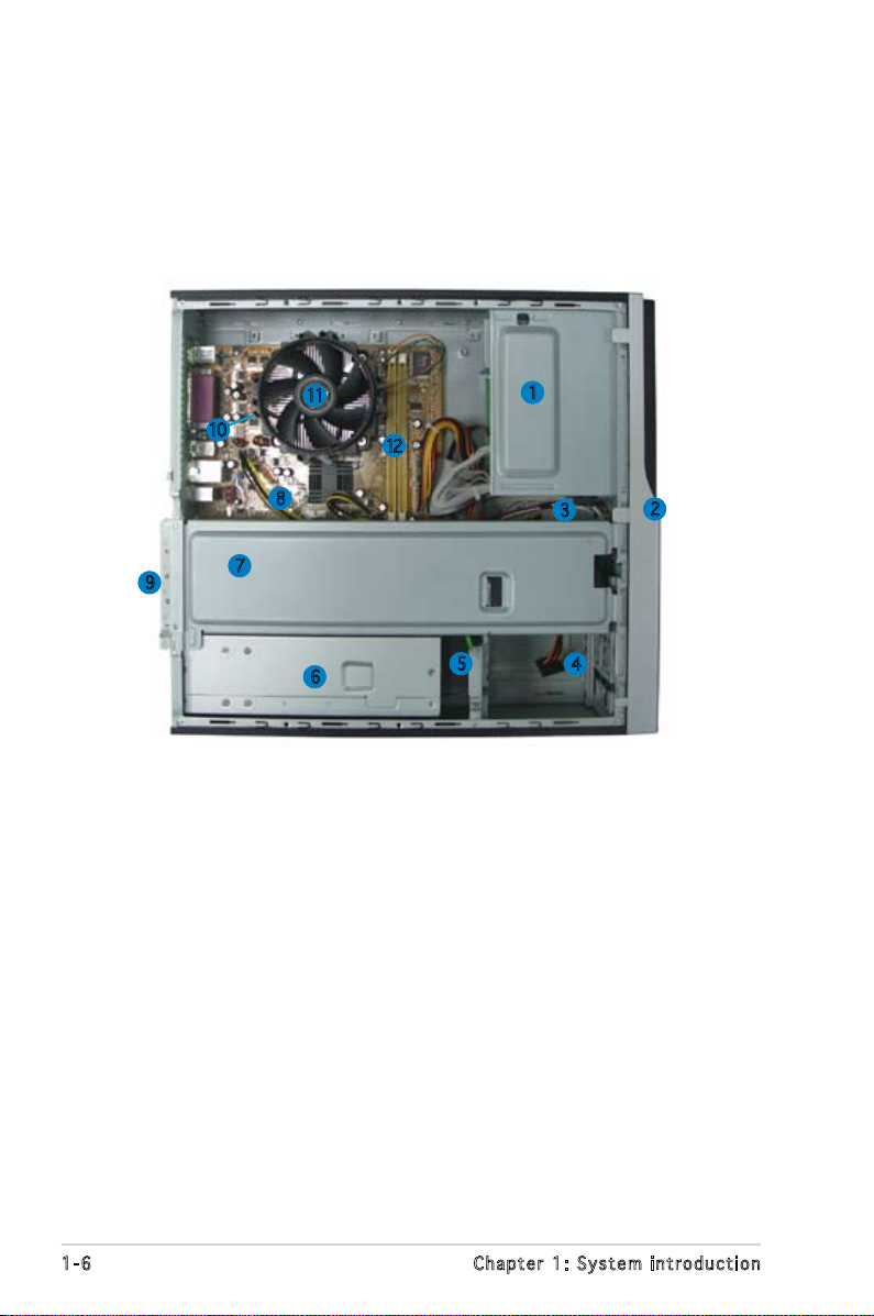
1.4 Internal components
The illustration below is the internal view of the system when you remove
the top cover. The installed components are labeled for your reference.
Proceed to Chapter 2 for instructions on installing additional system
components.
11
10
8
9
7
6
12
1. 5.25-inch empty optical drive bay
2. Front panel cover
3. Optical drive lock
4. Hard disk drive bays
5. Hard disk drive lock
6. Power supply unit
7. Chassis support bracket
1
3
5
4
2
8. ASUS motherboard
9. Metal bracket lock
10. LGA775 socket (under the CPU
fan and heatsink assembly)
11. CPU fan and heatsink assembly
12. DIMM sockets
1-6 Chapter 1: System introduction
Chapter 2
This chapter provides step-by-step
instructions on how to install
components in the system.
ASUS Pundit P3-PE5
Basic installation
2.1 Preparation
R
Onboard LED
SB_PWR
ON
Standby
Power
OFF
Powered
Off
Before you proceed, make sure that you have all the components you plan
to install in the system.
Bas i c c omp o ne n ts t o i nst a ll
1. Central Processing Unit (CPU)
2. DDR2 Dual Inline Memory Module (DIMM)
3. Expansion card(s)
4. Hard disk drive
5. Optical drive
Too l
Phillips (cross) screw driver
2.2 Before you proceed
Take note of the following precautions before you install components into
the system.
•
Use a grounded wrist strap or touch a safely grounded object or
a metal object, such as the power supply case, before handling
components to avoid damaging them due to static electricity.
•
Hold components by the edges to avoid touching the ICs on them.
•
Whenever you uninstall any component, place it on a grounded
antistatic pad or in the bag that came with the component.
The motherboard comes with an onboard standby power LED. This LED
lights up to indicate that the system is ON, in sleep mode or in soft-off
mode, and not powered OFF. Unplug the power cable from the power outlet
and make sure that the standby power LED is OFF before installing any
system component.
2-2 Chapter 2: Basic installation
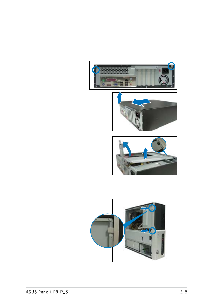
2.3 Removing the cover and front
panel assembly
To remove the cover:
1. Locate two cover
screws.
2. Remove the cover
screws.
3. Pull the cover.
4. Lift the cover, then set aside.
5. Lift the expansion card lock to
a 90º-100º angle.
6. Lift the chassis support
bracket, then remove.
To remove the front panel assembly:
1. Locate the front panel
assembly hooks.
2. Pull the hooks outward to
remove.
2-3ASUS Pundit P3-PE5
2.4 Central Processing Unit (CPU)
2.4 .1 Ove rv ie w
The motherboard comes with a surface mount LGA775 socket designed for
the Intel® Pentium® 4 processor in the 775-land package.
• Your boxed Intel® Pentium® 4 LGA775 processor package should
come with installation instructions for the CPU, heatsink, and the
retention mechanism. If the instructions in this section do not match
the CPU documentation, follow the latter.
•
Check your motherboard to make sure that the PnP cap is on the
CPU socket and the socket contacts are not bent. Contact your
retailer immediately if the PnP cap is missing, or if you see any
damage to the PnP cap/socket contacts/motherboard components.
ASUS will shoulder the cost of repair only if the damage is shipment/
transit-related.
•
Keep the cap after installing the motherboard. ASUS will process
Return Merchandise Authorization (RMA) requests only if the
motherboard comes with the cap on the LGA775 socket.
• The product warranty does not cover damage to the socket
contacts resulting from incorrect CPU installation/removal, or
misplacement/loss/incorrect removal of the PnP cap.
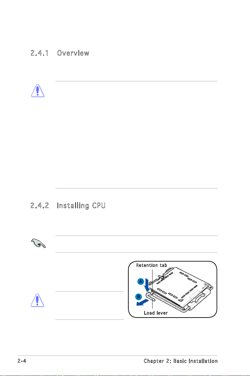
2.4 .2 Ins ta ll ing C PU
To install a CPU:
1. Locate the CPU socket on the motherboard.
Before installing the CPU, make sure that the socket box is facing
towards you and the load lever is on your left.
2. Press the load lever with your
Ret e n t ion t a b
thumb (A), then move it to the
left (B) until it is released from
the retention tab.
To prevent damage to the
socket pins, do not remove
the PnP cap unless you are
installing a CPU.
2-4 Chapter 2: Basic installation
A
B
Loa d l ever
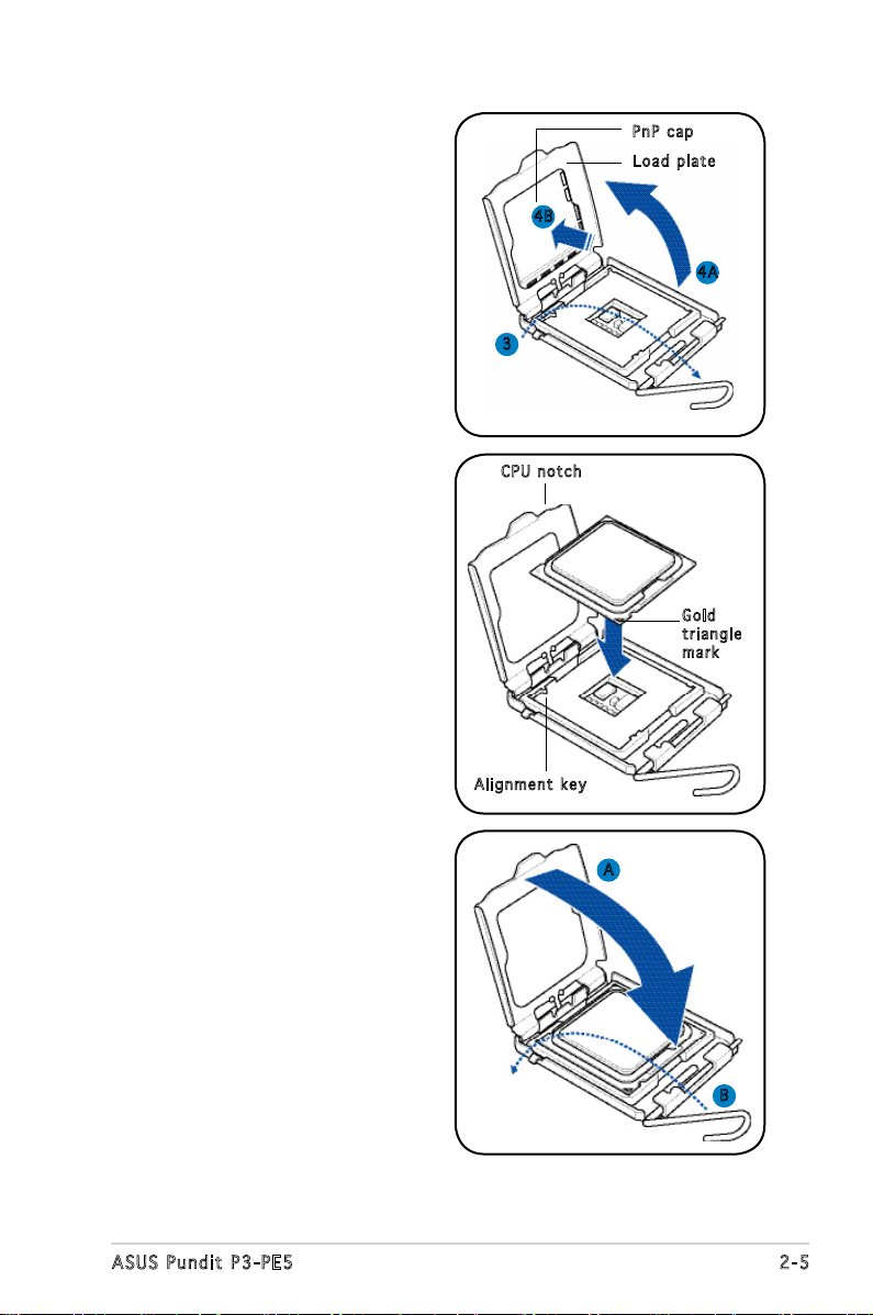
3. Lift the load lever in the
direction of the arrow to a 135º
angle.
PnP c a p
Loa d p late
4. Lift the load plate with your
thumb and forenger to a 100º
angle (4A), then push the PnP
cap from the load plate window
to remove (4B).
5. Position the CPU over the
socket, making sure that
the gold triangle is on the
bottom-left corner of the socket
then t the socket alignment
key into the CPU notch.
6. Close the load plate (A), then
push the load lever (B) until it
snaps into the retention tab.
4B
4A
3
CPU n o tch
Gol d
tri a n g le
mar k
Ali g n m ent k e y
A
B
2-5ASUS Pundit P3-PE5
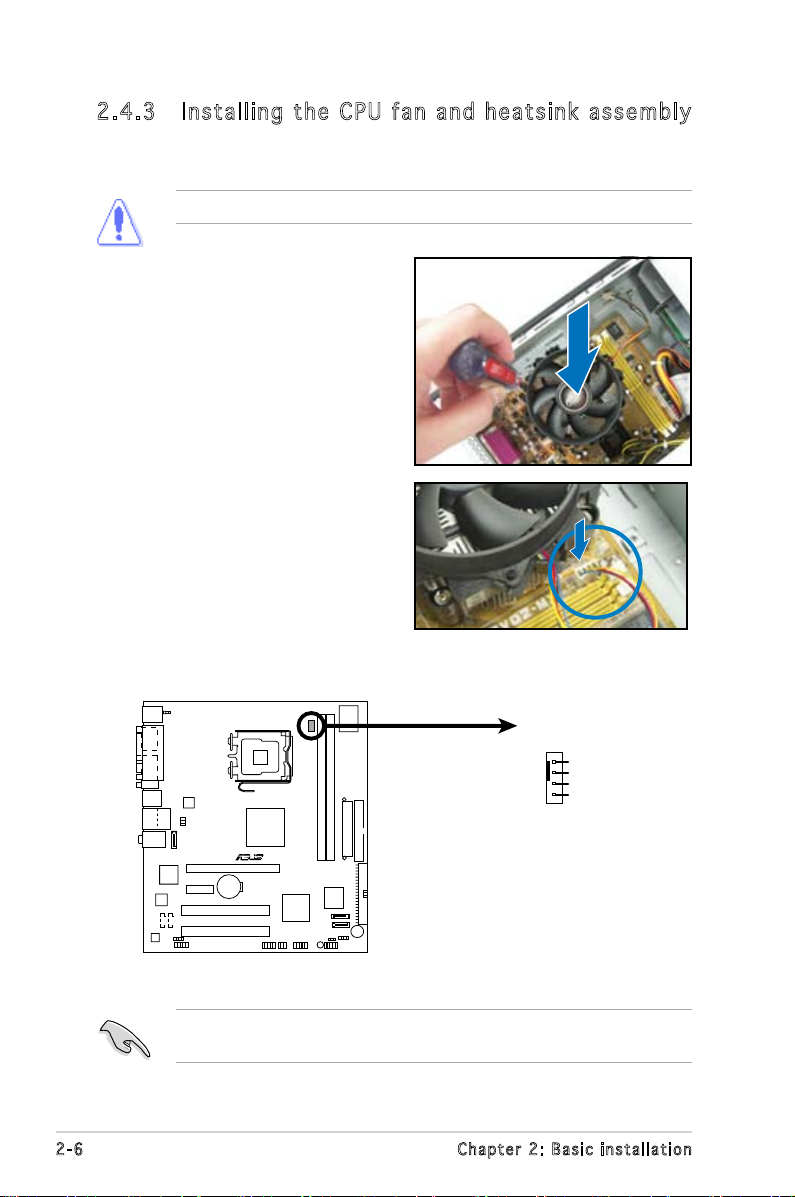
2.4 .3 Ins ta ll ing t he CP U f an a n d he a ts in k a ss em bly
R
Fan Connectors
CPU_FAN
GND
CPU FAN PWR
CPU FAN IN
CPU FAN PWM
The system package includes a proprietary CPU fan and heatsink assembly
to ensure optimum thermal condition and performance.
DO NOT replace the proprietary CPU fan and heatsink with other models!
To install the CPU fan and heatsink
assembly:
1. Place the heatsink on top of the
installed CPU.
2. Drive four screws into the fan
holes to secure the fan to the
motherboard.
3. Connect the CPU fan cable.
Refer to the gure below for the location of the CPU fan connector on
the motherboard.
Do not forget to connect the CPU fan connector! Hardware monitoring
errors can occur if you fail to plug this connector.
2-6 Chapter 2: Basic installation
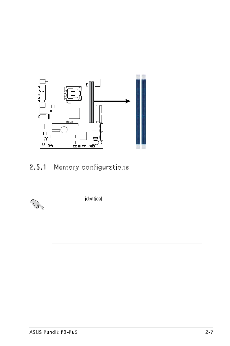
2.5 Installing a DIMM
R
240-pin DDR2 DIMM Sockets
DIMM1
DIMM2
The system motherboard comes with two Double Data Rate 2 (DDR2) Dual
Inline Memory Module (DIMM) sockets.
The following gure illustrates the location of the sockets:
2.5 .1 Mem or y con fi gu rat io ns
You may install up to 2 GB system memory using 256 MB, 512 MB, and 1
GB DDR2 DIMMs.
• Install only identical (the same type and size) DDR2 memory
modules.
• Install only ASUS-certied memory modules. Refer to the DDR2
Qualied Vendors List on the next page for details.
• Always install DIMMs with the same CAS latency. For optimum
compatibility, we recommend that you obtain memory modules from
the same vendor.
2-7ASUS Pundit P3-PE5
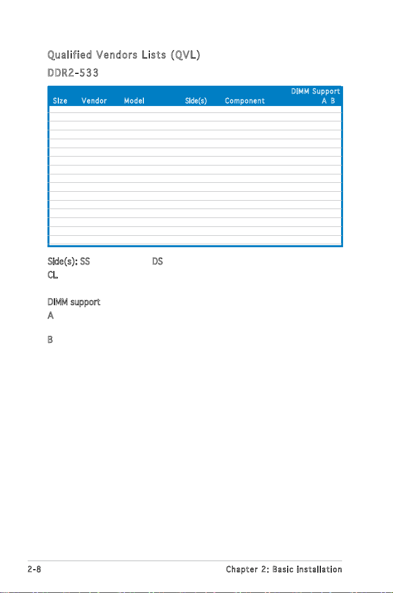
Qua l if i ed V en d ors Li s ts ( QV L )
DDR 2 -53 3
Siz e Ve n d o r Mod e l Side(s) C o m p onen t A B
DIM M S uppor t
512MB SAMSUNG K4T56083QF-GCD5 DS M378T6453FG0-CD5 V
5512MB Inneon HYB18T512800BF37 SS HYS64T64000HU-3.7-B V
1024MB Inneon HYB18T512800BF37 DS HYS64T128020HU-3.7-B V
512MB Hynix HY5PS12821AFP-C3 SS HYMP564U64AP8-C3 V
1024MB ELPIDA E5108AB-5C-E DS EBE11UD8ABFA-5C-E V
512MB CORSAIR MI110052432M8CEC DS VS512MB533D2 V
1024MB KINGMAX E5108AE-5C-E DS KLBD48F-A8EB4 V
512MB Transcend K4T51083QB-GCD5 SS TS64MLQ64V5J V
256MB Aeneon AET960UD00-37C88X SS AET560UD00-370A98X V
512MB Aeneon AET960UD00-37C88X SS AET660UD00-370A98X V
512MB Aeneon AET93F370AG0513 SS AET660UD00-370A98X V
512MB NANYA NT5TU64M8AF-37B SS NT512T64U88A0F-37B V
512MB PQI 64MX8D2-E SS MEAB-423LA V
256MB SimpleTech 858S032F25A SS SVM-42DR2/256 V
1024MB Patriot Heat-Sink Package SS PDC21G5600+XBLK V
1024MB MDT 18D51280D-3.70448 DS M924-533-16 V V
Side(s): SS - Single-sided DS - Double-sided
CL: CAS Latency
DIMM support:
A - Supports one module inserted into either slot, in Single-channel
memory conguration.
B - Supports one pair of modules inserted into both slots as one pair
of Dual-channel memory conguration.
2-8 Chapter 2: Basic installation
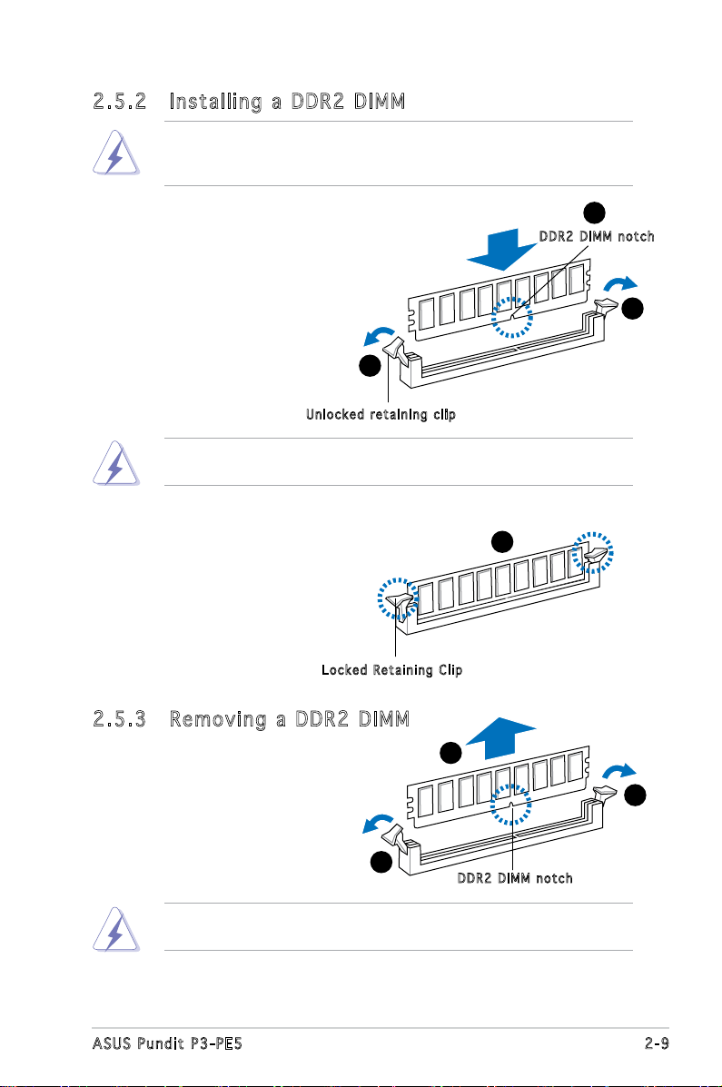
2.5 .2 Ins ta ll ing a D DR2 D IM M
Make sure to unplug the power supply before adding or removing DIMMs
or other system components. Failure to do so may cause severe damage
to both the motherboard and the components.
1. Unlock a DDR2 DIMM socket
by pressing the retaining clips
outward.
2. Align a DIMM on the socket
such that the notch on the
DIMM matches the break on
the socket.
Unl o c k ed re t a i ning c l i p
A DDR2 DIMM is keyed with a notch so that it ts in only one direction.
DO NOT force a DIMM into a socket to avoid damaging the DIMM.
1
2
DDR 2 D IMM n o t c h
1
3. Firmly insert the DIMM into the
socket until the retaining clips
snap back in place and the DIMM
is properly seated.
Loc k e d Reta i n i ng Cl i p
2.5 .3 Rem ov in g a D DR 2 D IM M
Follow these steps to remove a DIMM.
1. Simultaneously press the
retaining clips outward to
unlock the DIMM.
1
Support the DIMM lightly with your ngers when pressing the retaining
clips. The DIMM might get damaged when it ips out with extra force.
2. Remove the DIMM from the socket.
3
2
1
DDR 2 D IMM n o t c h
2-9ASUS Pundit P3-PE5
2.6 Expansion slots
In the future, you may need to install expansion cards. The motherboard
has two PCI, one PCI Express™ x1, and one PCI Express™ x16 slot. The
following sub-sections describe the slots and the expansion cards that they
support.
The system supports low prole PCI, PCI Express x16, and PCI Express
x1 cards. You can only install low prole expansion cards on this system.
Ask your retailer for details.
2.6 .1 Exp an si on sl ot s
PCI sl o ts
The PCI slots support cards such as a LAN card, SCSI card, USB card,
andother cards that comply with PCI specications.
PCI Ex p res s x 1 6 s l ot
This motherboard supports PCI Express x16 graphic cards that comply with
the PCI Express specications. The following gure shows a graphics card
installed on the PCI Express x16 slot.
PCI Ex p res s x 1 sl o t
This motherboard supports PCI Express x1 network cards, SCSI cards and
other cards that comply with the PCI Express specications.
Before installing an expansion card, read the documentation that came
with it and make the necessary hardware settings for the card.
2.6 .2 Exp an si on ca rd in st al lat io n
Make sure to unplug the power cord before adding or removing
expansion cards. Failure to do so may cause you physical injury and
damage motherboard components.
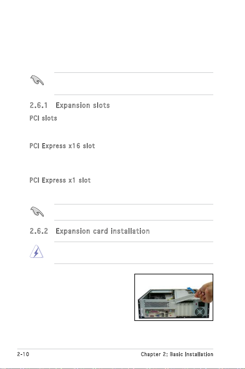
To install an expansion card:
1. Lay the system on its side on a
at and stable surface.
2. Lift the expansion card lock to a
90º-100º angle.
2-10 Chapter 2: Basic installation
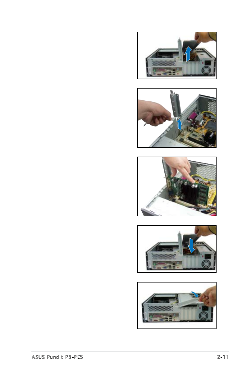
2. Remove the chassis support
bracket.
3. Remove the metal cover opposite
the slot that you intend to use.
4. Align the card connector with
the slot and press rmly until
the card is completely seated
on the slot.
5. If you have already installed a hard
disk drive, replace the chassis
support bracket; otherwise,
install other components before
replacing the chassis support
bracket.
6. Replace the expansion card lock
to secure the card to the chassis.
2-11ASUS Pundit P3-PE5
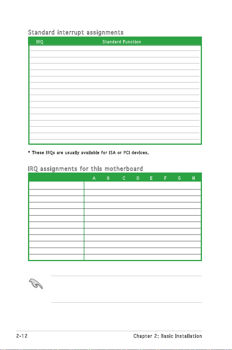
Sta n da r d i n te r rup t a s sig n me n ts
IRQ S tand a r d Func t i o n
0 System Timer
1 Keyboard Controller
2 Re-direct to IRQ#9
3 IRQ holder for PCI steering*
4 Communications Port (COM1)*
5 IRQ holder for PCI steering*
6 Floppy Disk Controller
7 Printer Port (LPT1)*
8 System CMOS/Real Time Clock
9 IRQ holder for PCI steering*
10 IRQ holder for PCI steering*
11 IRQ holder for PCI steering*
12 PS/2 Compatible Mouse Port*
13 Numeric Data Processor
14 Primary IDE Channel
15 Secondary IDE Channel
* T h e s e IRQ s a re us u a l l y av a i l a ble f o r ISA o r P CI d e v i c es.
IRQ as s ign m en t s f o r t his mo t her b oa r d
A B C D E F G H
PCI slot 1 shared — — — — — — —
PCI slot 2 — shared — — — — — —
PCI Express x 16 slot shared — — — — — — —
PCI Express x 1 slot — shared — — — — — —
Onboard USB controller 1 — — — — — — — shared
Onboard USB controller 2 — — — shared — — — —
Onboard USB controller 3 — — shared — — — — —
Onboard USB controller 4 — — — shared — — — —
Onboard USB 2.0 controller — — — — — — — shared
Onboard IDE port — — — shared — — — —
Onboard HD audio shared — — — — — — —
Onboard LAN — shared — — — — — —
When using PCI cards on shared slots, ensure that the drivers support
“Share IRQ” or that the cards do not need IRQ assignments. Otherwise,
conicts will arise between the two PCI groups, making the system
unstable and the card inoperable.
2-12 Chapter 2: Basic installation
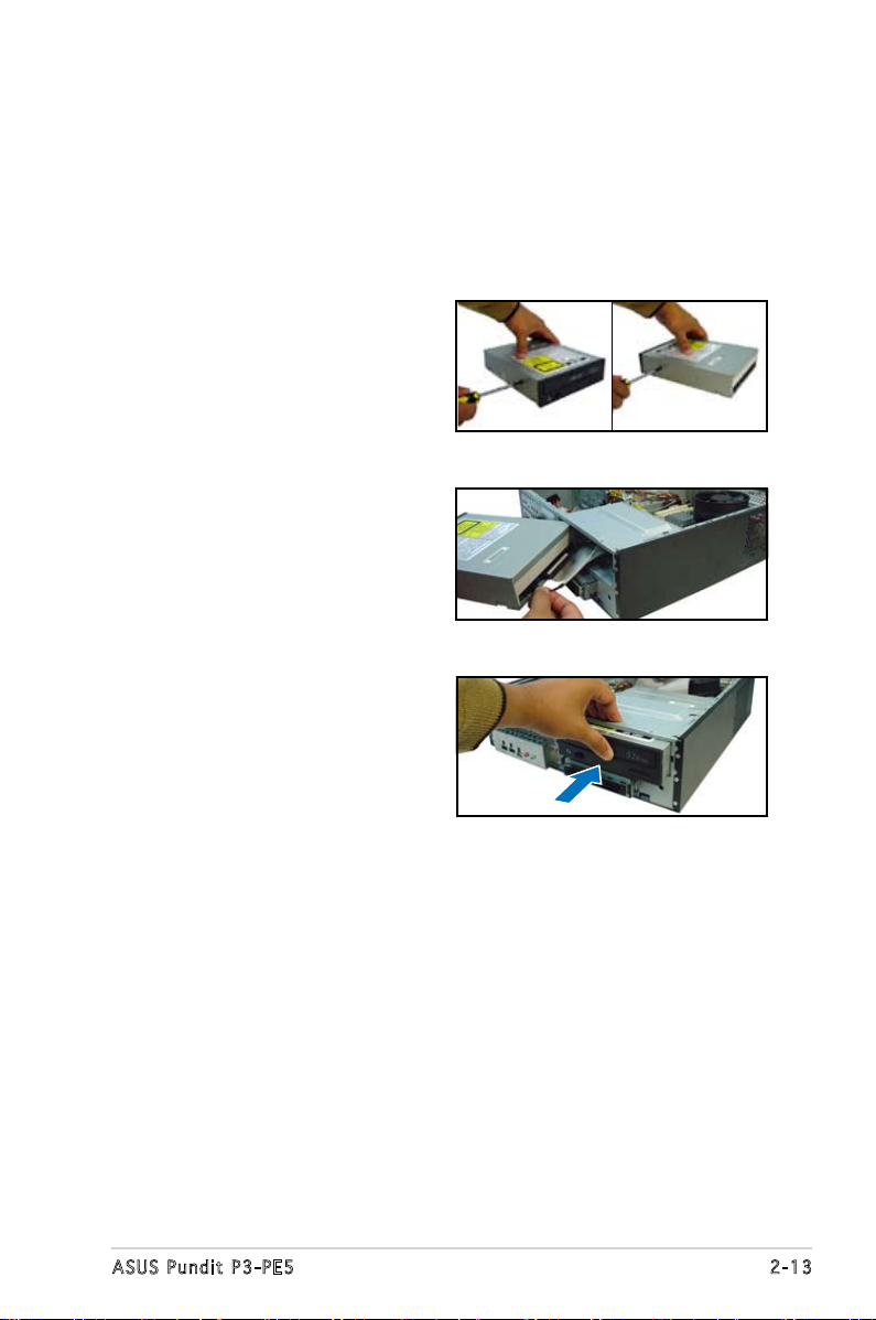
2.7 Installing an optical drive
Refer to the instructions in this section if you wish to install a new optical
drive.
Follow these steps to install an optical drive:
1. Drive a screw on the top right
screw hole on both sides of
the drive.
2. Connect the IDE and audio
cable at the back of the drive.
3. Push the drive all the way into
the bay until the drive lock clicks.
4. Connect a 4-pin power plug
from the power supply unit to
the power connector at the
back of the drive.
2-13ASUS Pundit P3-PE5
 Loading...