

Page 1
Pundit P3-PE5/P3-AE5
ASUS PC (Desktop Barebone)
Quick Installation Guide
Download the latest manual from the ASUS website: www.asus.com.
Page 2
2 Quick Installation Guide
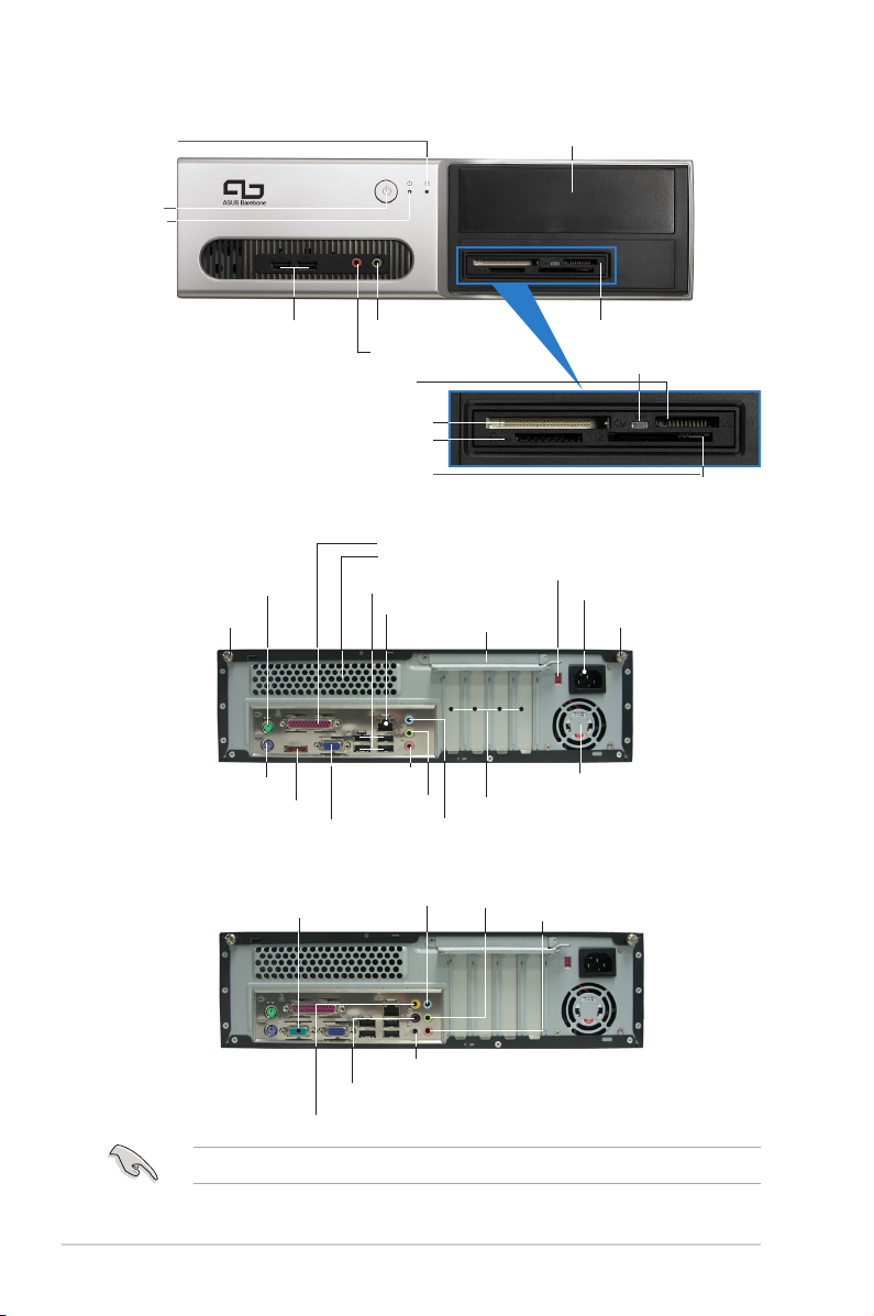
Rear panel features (P3-PE5)
Front panel features
Rear panel features (P3-AE5)
5.25-inch drive bay cover
HDD LED
USB 2.0 ports Microphone port
Headphone port
6-in-1 card reader
CompactFlash® card slot
Secure Digital™/MultimediaCard slot
SmartMedia® card slot
Card reader LED
Memory Stick/Pro™ card slot
Power
button
Power
LED
COM port
Side Surround L/R
Rear Surround L/R
Center/sub
The systems only support Low Profile PCI card.
PS/2 keyboard port
Cover screw
Cover screw
PS/2 mouse port
Parallel port
Line In
Voltage selector
Metal bracket lock
Power connector
VGA port
E-SATA port
USB 2.0 ports
MIC in
Line Out
PCI slot metal brackets
Power fan vent
Air vents
LAN (RJ-45) port
Line In
Line Out
MIC in
Page 3
3Quick Installation Guide
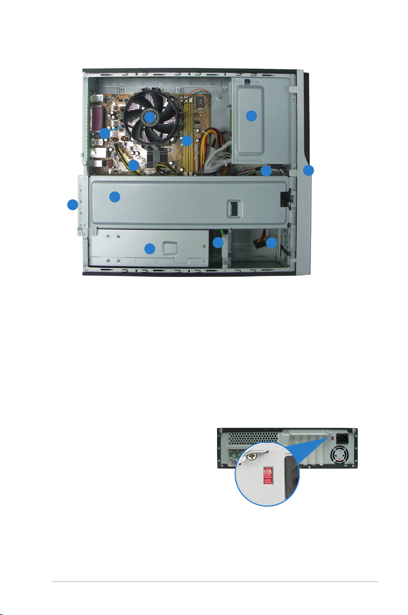
Internal components
8
1
2
9
1. 5.25-inch empty optical drive bay
2. Front panel cover
3. Optical drive lock
4. Hard disk drive bays
5. Hard disk drive lock
6. Power supply unit
7. Chassis support bracket
8. ASUS motherboard
9. Metal bracket lock
10. LGA775 socket for P3-PE5,
AM2 socket for P3-AE5 (under
the CPU fan and heatsink
assembly)
11. CPU fan and heatsink assembly
(P3-AE5 system doesnʼt
bundle with it)
12. DIMM sockets
Selecting the voltage
The systemʼs power supply unit has
a 115 V/230 V voltage selector
switch located beside the power
connector. Use this switch to select
the appropriate system input voltage
according to the voltage supply in
your area.
If the voltage supply in your area is
100-127 V, set the switch to 115 V.
If the voltage supply in your area is
200-240 V, set the switch to 230 V.
3
5
4
7
6
12
10
11
Page 4

4 Quick Installation Guide
3. Pull the cover.
Removing the cover
1. Locate two cover screws.
2. Remove the cover screws.
4. Lift the cover, then set aside.
Removing the front panel assembly
1. Locate the front panel
assembly hooks.
2. Pull the hooks outward to
remove.
5. Lift the expansion card lock to
a 90º-100º angle.
6. Lift the chassis support
bracket, then remove.
Page 5

5Quick Installation Guide
Installing a CPU (P3-PE5)
1. Locate the CPU socket, then
unlock and lift the load lever.
2. Lift the load plate (A), then
push the PnP cap from the load
plate window (B).
Retention
tab
Load
lever
Load plate
B
A
4. Close the load plate (A), then
lock the load lever (B).
3. Install the CPU.
Gold triangle
mark
A
B
Installing a CPU (P3-AE5)
1. Locate the CPU socket, then unlock the socket by pressing the lever
sideways and lift it up to a 90º angle.
2. Match the gold triangle of the CPU with the socket corner with a small
triangle, then carefully insert the CPU into the socket.
3. When the CPU is in place, push down the socket lever to secure the
CPU.
Socket
lever
Gold
triangle
Small
triangle
Page 6

6 Quick Installation Guide
Installing the CPU fan and heatsink
assembly (P3-PE5)
1. Place the heatsink on top of the
installed CPU.
2. Drive four screws into the fan
holes to secure the fan to the
motherboard.
3. Connect the CPU fan cable.
P3-AE5 does not bundle
with the CPU fan and
heatsink assembly. Please
use the AMD CPU box cooler
Installing a DIMM
1. Locate the DIMM sockets in
the motherboard.
2. Unlock a DIMM socket by
pressing the retaining clips
outward.
3. Align a DIMM on the socket
such that the notch on the
DIMM matches the break on
the socket.
DDR2 DIMM notch
1
2
1
Installing the CPU fan and heatsink assembly
(P3-AE5)
1. Place the heatsink on top of
the installed CPU.
2. Attach one end of the
retention bracket to the
retention module base.
3. Align the other end of the
retention bracket (near the
retention bracket lock) to the
retention module base.
4. Push down the retention
bracket lock.
5. Connect the CPU fan cable to the connector on the motherboard
labeled CPU_FAN.
1
3
4
5
2
CPU Fan
CPU
Heatsink
Retention
bracket
Retention bracket lock
Retention
Module Base
Page 7

7Quick Installation Guide
1. Remove the metal cover
opposite the slot that you
intend to use.
2. Insert the card connector to
the slot, then press the card
firmly until it fits in place.
Installing an expansion card
Installing an optical drive
1. Drive a screw on the top right
screw hole on both sides of
the drive.
2. Connect the IDE and audio
cable at the back of the drive.
3. Push the drive all the way into
the bay until the drive lock clicks.
4. Connect a 4-pin power plug
from the power supply unit to
the power connector at the
back of the drive.
Installing a SATA hard disk drive
1. Drive two screws with rubber
washers on both sides of the
drive.
2. Connect the SATA signal and
power plug at the back of the
drive.
Power cable and
plug
Signal cable and
plug
Rubber washer
Page 8

8 Quick Installation Guide
3. Place the HDD on the tray. 4. When the HDD screws align,
push the drive on the bay.
1. Replace the front panel
assembly. Remove the 5.25”
drive bay cover when you
installed an optical drive.
3. Insert the cover hooks to the
holes on the chassis side.
2. Reinstall the metal chassis
support and the expansion
card lock.
Replacing the covers
4. Push the cover to the direction
of the front panel, then
replace the cover screws.
 Loading...