

®
Pundit-PE2
1
2
©2005
Pundit-PE2
V1 T1932
2005 3
2
ASUSTeK COMPUTER INC.
15
886-2-2894-3447
0800-093-456
886-2-2890-7698
tw.asus.com
ASUS COMPUTER INTERNATIONAL
44370 Nobel Drive, Fremont ,CA 94538, USA
+1-510-608-4555
tmdl@asus.com
+1-502-933-8713
+1-502-995-0883
http://vip.asus.com/eservice/techserv.aspx
www.asus.com
ASUS COMPUTER GmbH
Harkort Str. 25, D-40880 Ratingen, Germany
49-2102-95990
49-2102-959911
www.asuscom.de
www.asuscom.de/sales
49-2102-95990 ... /
49-2102-959910 ...
49-2102-959911
www.asuscom.de/support
3
........................................................................................
........................................................................................
..........................................................................................................
............................................................................................
........................................................................................
..........................................................................................
.................................................
1.1
1.2
1.3
1.4
1.5
...............................................................................................
...........................................................
...........................................................
...................................................................................
...............................................................................
.................................................
2.1
2.2
2.3
2.4 CPU
2.4.1 CPU
2.4.2
2.4.3 CPU
2.5
2.6
2.7
2.8
...................................................................................
...............................................................................
...................................................................................
...................................................................
..........................................................................
........................................................................
......................................................
.................................................................................
.....................................................................................
.................................................................................
.....................................................................
2
3
4
7
8
10
1-1
1-3
1-3
1-4
1-5
1-6
2-1
2-3
2-5
2-5
2-7
2-7
2-8
2-9
2-10
2-11
2-12
2-13
.................................................
3.1
3.2
4
...............................................................................
.......................................................................................
3-1
3-3
3-3
6
3.3
3.3.1
3.3.2 Drivers Menu
3.3.3 Utilities Menu
3.3.4
3.4
3.4.1
3.4.2
3.4.3
3.5
3.5.1
3.5.2
3.5.3
.......................................................................
...............................................................................
............................................................................
....................................................................................
................................................................................
.........................................................................
...................................................
...............................................
..............................................................
..............................................................
..................................................
..............................................
4.1
4.2
4.3
BIOS
5.1 BIOS
5.1.1 EZ Flash BIOS
5.1.2 CrashFree BIOS 2 BIOS
5.1.3
5.2 BIOS
5.2.1 BIOS
5.2.2
5.2.3
5.3 Main Menu
5.3.1 Primary & Secondary Master/Slave
...............................................................................
...................................................................
.......................................................................................
........................................
........................................................
............................................................................
.....................................................................................
................................................................
..................................................................
......................................................................
..................................................................
.....................................
....................................
3-10
3-10
3-11
3-13
4-1
5-1
................................
.........................
5-10
5-10
5-11
5-12
.........................
5-14
3-4
3-4
3-5
3-5
3-6
3-7
3-7
3-8
3-9
4-3
4-4
4-5
5-3
5-3
5-5
5-6
5-9
5
5.3.2
5.4 Advanced Menu
5.4.1 Chip Configuration
5.4.2 PCI Configuration PCI
5.5 Power Menu
5.5.1 Power Up Control
5.5.2 Hardware Monitor
5.6 Boot Menu
5.7 Exit Menu
..........................................................................
5-17
......................................................
...................................
..................................................
....................................................
.........................................
........................................
...............................................................
................................................................
5-18
5-20
5-22
5-24
5-26
5-27
5-28
5-30
1) Pundit-PE2
•
CPU
•
IDE
•
2)
AC
•
•
•
3) Support CD
4)
5)
•
DVD-ROM Combo DVD RW
7
1.
2.
step-by-step
3.
4.
Jumper
5. BIOS
BIOS BIOS
Pundit-PE2
Pundit-PE2
8
1.
2.
http://tw.asus.com
3
9
•
•
•
•
•
•
•
•
10
•
•
•
•
•
IC
Pundit-PE2
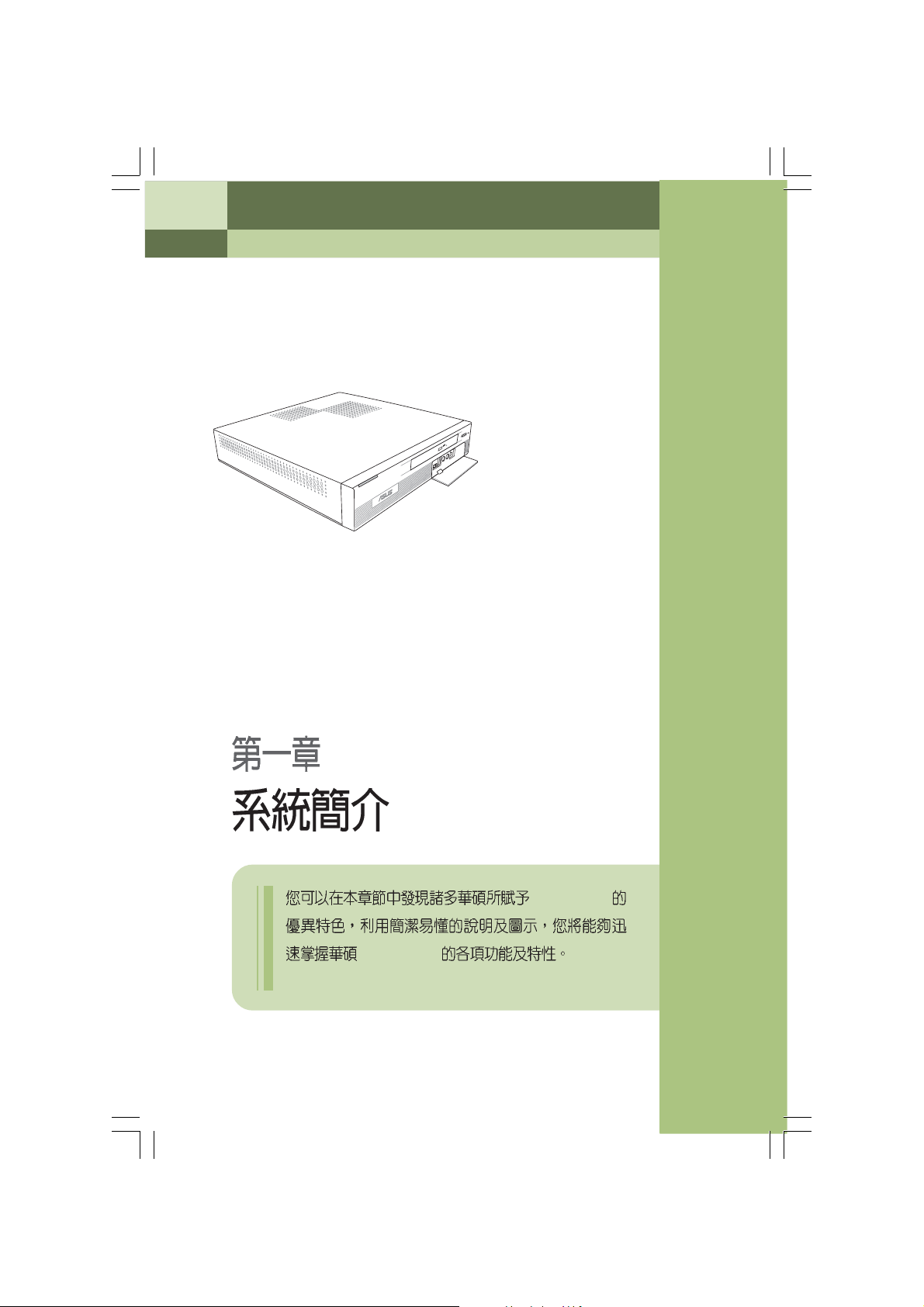
System Introduction
Pundit-PE2
1.1
1.2
1.3
1.4
1.5
...............................................................................................
...........................................................
...........................................................
...................................................................................
...............................................................................
1-3
1-3
1-4
1-5
1-6
1-2
1.1
1.2
Pundit-PE2
Pundit-PE2
CPU
4
2
1
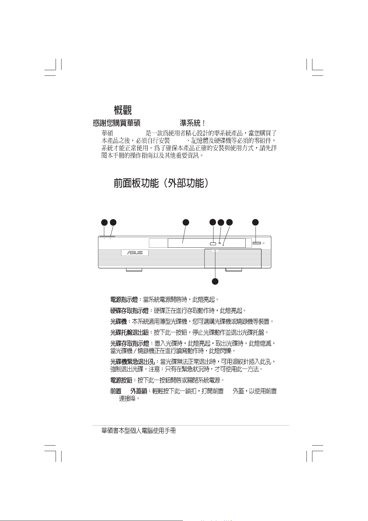
1.
2.
3.
4.
5.
6.
7.
8. I/O I/O
I/O
3
6
5
8
7
1-3
1.3
16
19 20 21 22 23
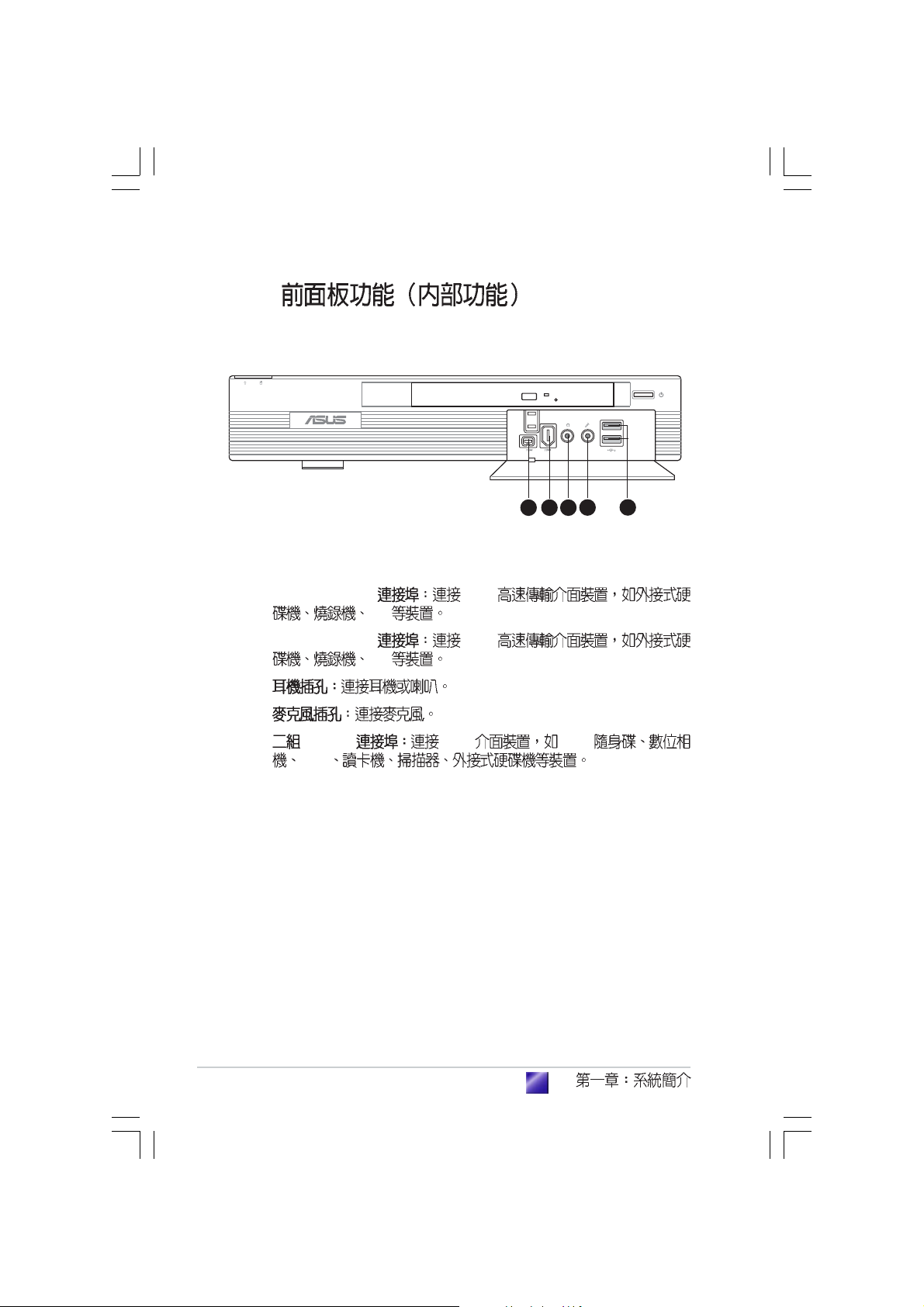
9. 4-pin IEEE 1394 1394
DV
10.6-pin IEEE 1394 1394
DV
11.
12.
13. USB 2.0 USB USB
PDA
119 10
1312
1-4
1.4
1.
2.
3.
1 2 3
4 5
9
8
7 6
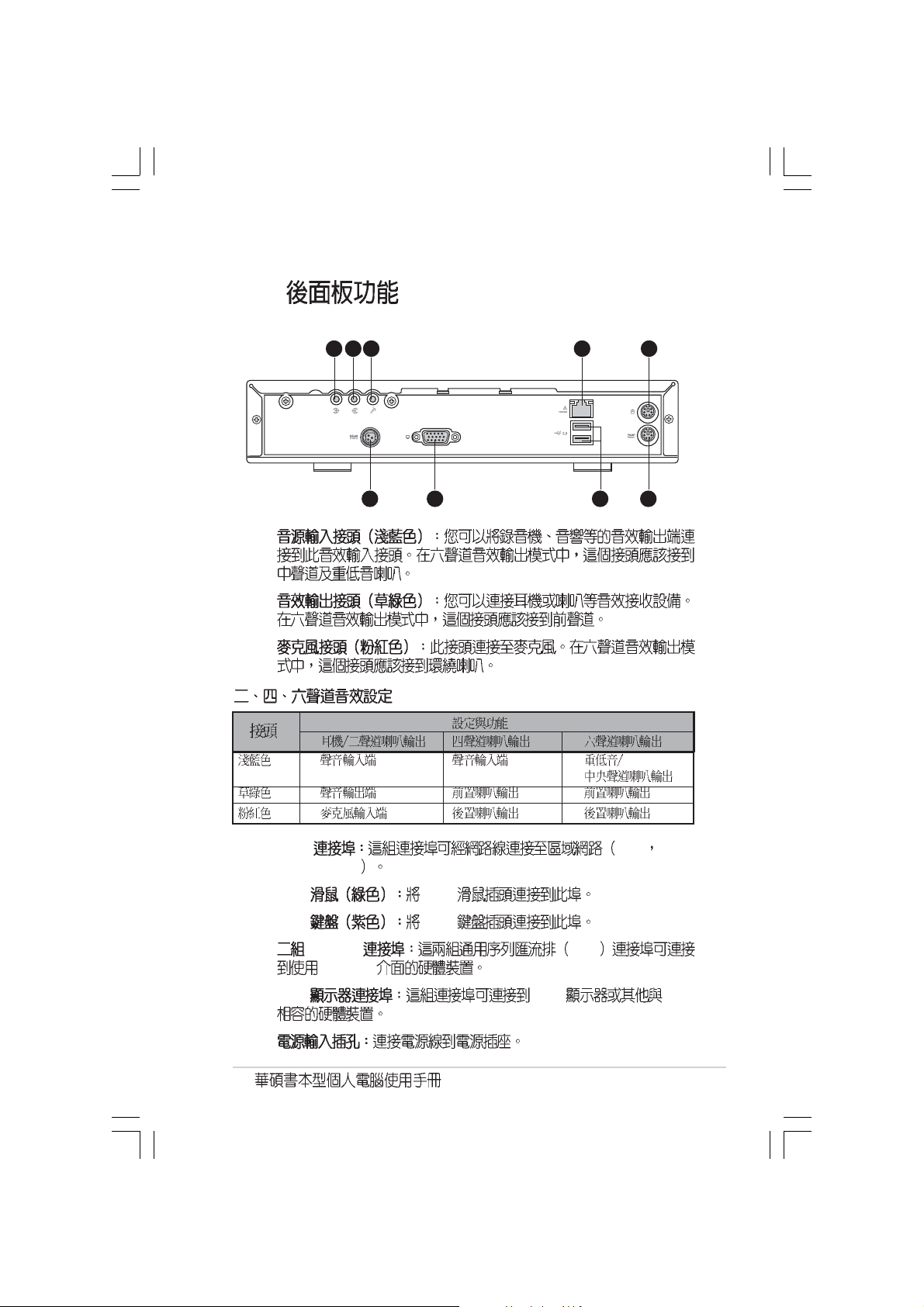
4. LAN LAN Local
Area Network
5. PS/2 PS/2
6. PS/2 PS/2
7. USB2.0 USB
USB 2.0
8. VGA VGA VGA
9.
1-5
1.5
4
1
2
3
7
5
6
8
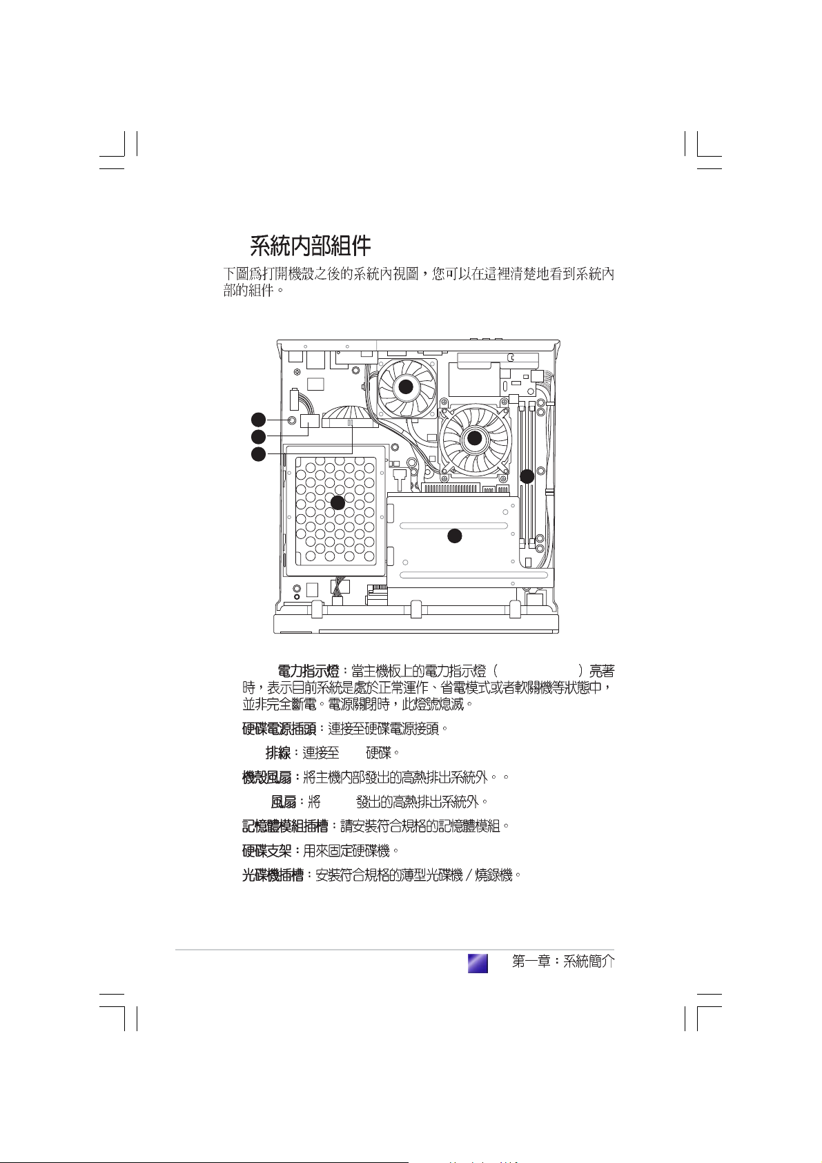
1. LED SBPWRLED
2.
3. IDE IDE
4.
5. CPU CPU
6.
7.
8.
1-6
step-by-step
Starting up
2.1
2.2
2.3
2.4 CPU
2.4.1 CPU
2.4.2
2.4.3 CPU
2.5
2.6
2.7
2.8
...................................................................................
...............................................................................
...................................................................................
.................................................................................
.....................................................................................
.................................................................................
2-3
2-5
2-5
...................................................................
..........................................................................
........................................................................
......................................................
.....................................................................
2-7
2-7
2-8
2-9
2-10
2-11
2-12
2-13
2.1
1. CPU
2.
3.
1.
2.
3.
4.
5.
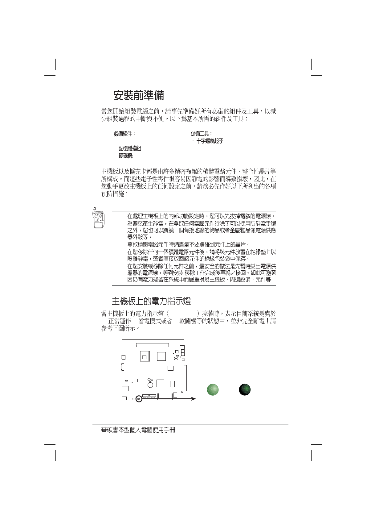
SB_PWR
(1) (2) (3)
/
Onboard LED
SBPWRLED
ON
Standby
Power
OFF
Powered
Off
2-3
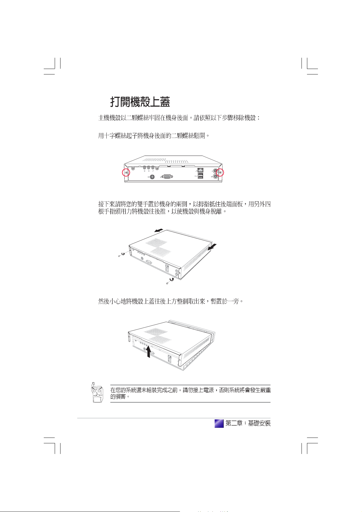
2.2
1.
2.
2-4
3.
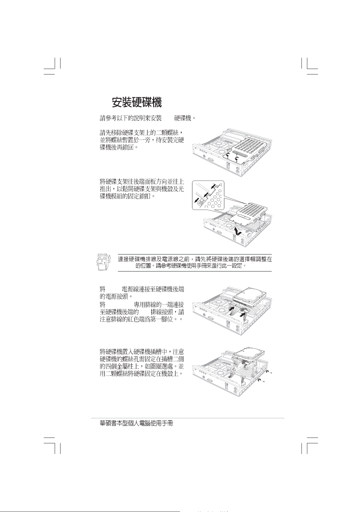
2.3
1.
2.
IDE
Master
3. 4-pin
4. 40-pin IDE
5.
IDE
2-5

6.
7.
2-6
2.4 CPU
ZIF Intel Pentium 4
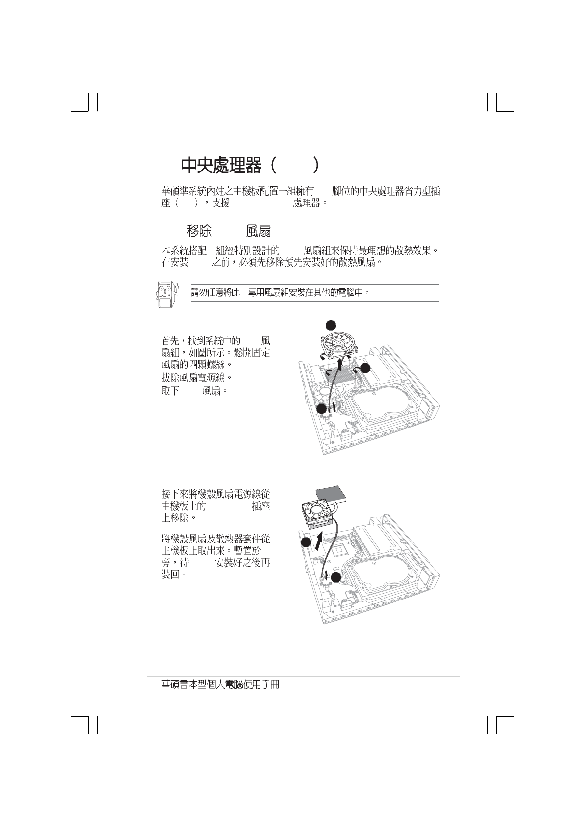
2.4.1 CPU
CPU
CPU
1. CPU
2.
3. CPU
478
3
1
2
4.
5.
CHA_FAN
5
CPU
4
2-7
2.4.2 CPU
˚
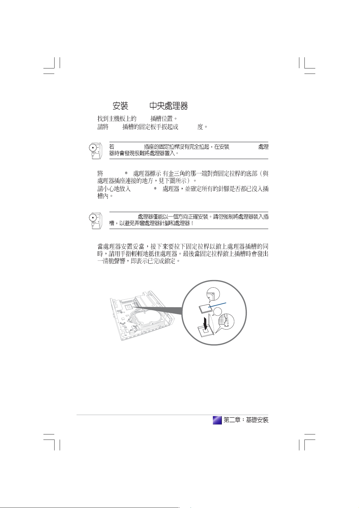
1. CPU
2. CPU 90-100
Socket-478 Pentium
3. Pentium 4 .
4. Pentium 4
Pentium
®
4
5.
CPU
®
4
2-8
2.4.3 CPU
CPU CPU
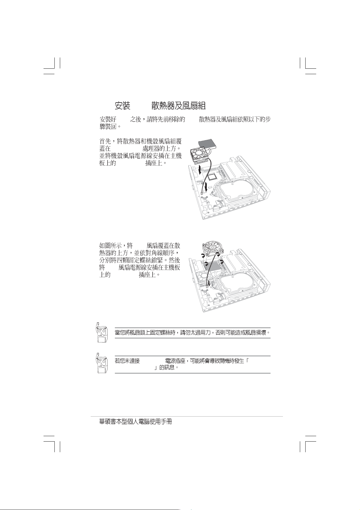
1.
Pentium
®
4
CHA_FAN
2. CPU
CPU
CPU_FAN
CPU_FAN Hardware
monitoring errors
2-9
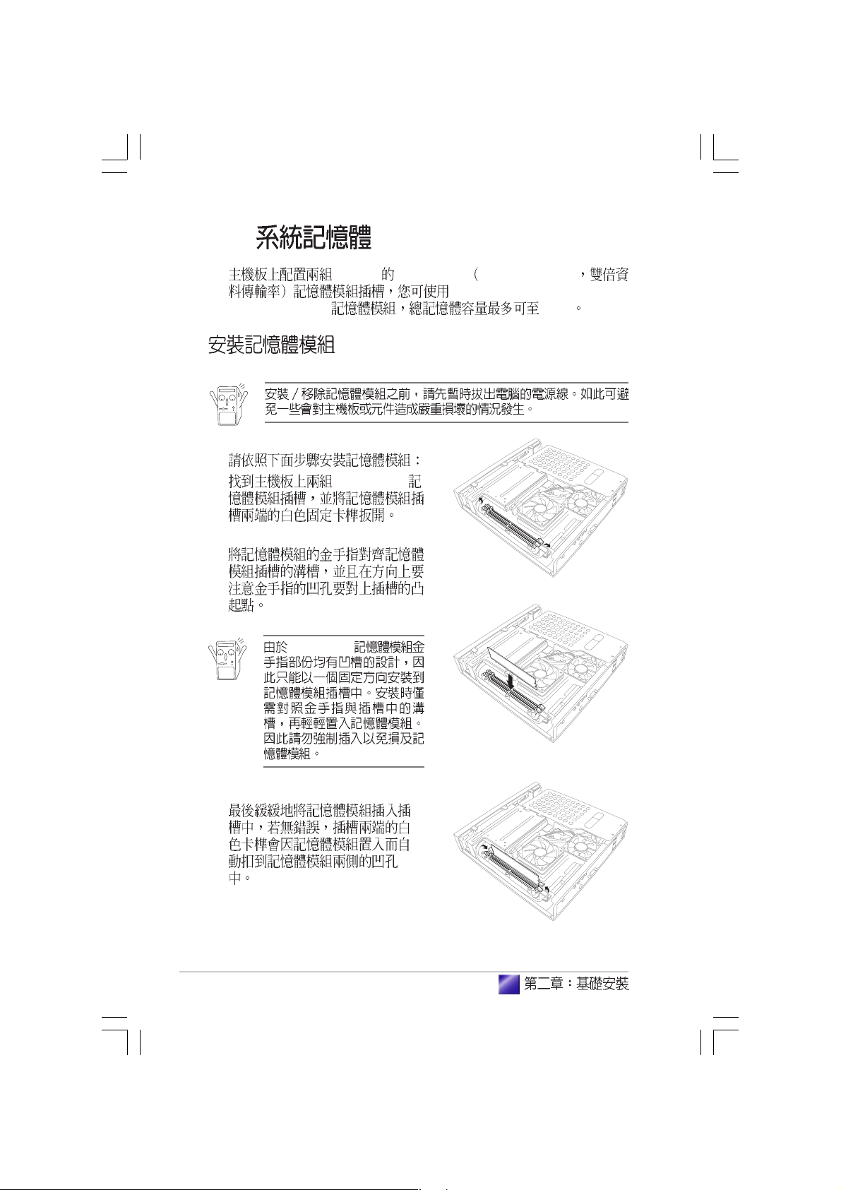
2.5
184-pin DDR DIMM Double Data Rate
unbuffered non-ECC 2700/2100/
1600 DDR DIMM 2 GB
1. DDR DIMM
2.
DDR DIMM
2-10
3.

2.6
1.
2.
2-11

2.7
100V 240V
1.
2.
3. LED
4. DCIN
4
2
2-12
3
1

2.8
VGA
Hub Router
USB
PS/2
PS/2
2-13

2-14

Getting started

3.1
3.2
3.3
3.3.1
3.3.2 Drivers Menu
3.3.3 Utilities Menu
3.3.4
3.4
3.4.1
3.4.2
3.4.3
3.5
3.5.1
3.5.2
3.5.3
...............................................................................
.......................................................................................
...................................................
.......................................................................
...............................................................................
............................................................................
....................................................................................
................................................................................
.........................................................................
..............................................................
..............................................................
..................................................
3-3
3-3
3-4
...............................................
.....................................
....................................
3-4
3-5
3-5
3-6
3-7
3-7
3-8
3-9
3-10
3-10
3-11
3-13
3-2

3.1
Windows 2000/XP
Windows
Windows
3.2
Windows Windows
Windows
3-3

3.3
3.3.1
Support CD
http://tw.asus.com.
3-4
BIN ASSETUP.EXE

3.3.2 Drivers menu
SiS 651
SiS 651
AD1980
AD1980 SoundMAX
SiS PCI
SiS PCI
SiS Mini IDE
SiS Mini IDE
USB 2.0
USB 2.0
3.3.3 Utilities menu
3-5

Microsoft DirectX
Microsoft DirectX 9.0c
Adobe Acrobat Reader
Adobe Acrobat Reader PDF Portable Document
Format
3.3.4
CPU
BIOS
TCP/IP
3-6

3.4
3.4.1
SoundMAX
5.1
SoundMAX SoundMAX
5.1
Multi-drive
3-7

3.4.2
MIDI
3-8

DVD
AC3 SPDIF PCM SPDIF
3.4.3
Mic2 Select
3-9

3.5 PC Probe
CPU
3.5.1
ASUS Utility\Probe Vx.xx Vx.xx
Show up in next execution
3-10

3.5.2
CPU
CPU
CPU
CPU
CPU
3-11

3-12
FAT

DMI
CPU
3.5.3
CPU
CPU !!!
3-13


Jumper
Motherboard Information

4.1
4.2
4.3
...............................................................................
...................................................................
.......................................................................................
4-3
4-4
4-5

4.1
ADAPTER
VGA
LAN_USB78
PS/2
T:Mouse
B:Keyboard
CHA_FAN
CPU_FAN
IDEPWR
DDR DIMM2 (64/72-bit, 184-pin module)
DDR DIMM1 (64/72-bit, 184-pin module)
Socket 478
RTL
8201BL
SBPWRLED
BUZZER
27.2cm (10.7in)
CLRTC
CR2032 3V
Lithium Cell
CMOS Power
PRI_IDE
SiS 651
Host
Memory
Controller
SiS
962L
USB34
FONT
MIC
AD1980
IE1394_1
FONT
LOUT
IE1394_2
PWRSW
VIA
VT6307
AUD_CON
CD
AUX
26.9cm (10.6in)
UA
PCI1
Super
I/O
4 Mb
ISA
LED_CON
4-3

4.2
BIOS Clear RTC RAM CLR_RTC
CMOS
CMOS
1
2
3 CLRTC [2-3] CMOS
4 CLRTC [1-2]
5
6 <Del> BIOS
BIOS
CLRTC
2312
Normal
(Default)
Clear CMOS
4-4
Clear RTC RAM

4.3
1. IDE 40-1 pin PRI_IDE
IDE IDE
IDE CD-ROM ZIP MO
IDE
Master Slave
1. IDE
UltraDMA
2. UltraDMA133/100/66
PIN 1
IDE connector
PRI_IDE
NOTE: Orient the red markings
(usually zigzag) on the IDE
ribbon cable to PIN 1.
PIN1
UltraDMA133/100/66 IDE
80 IDE
80 IDE UltraDMA 133/100/66
4-5

2. 3-pin
CPU_FAN, CHA_FAN
350mA 4.2 12
RPM Rotations Per
Minute
CPU
CPU jumpers
jumper
CHA_FAN CPU_FAN
Rotation
GND
+12V
Rotation
Fan connectors
3. (4-pin AUX1, CD1)
CD1 CD-ROM AUX1 TV/FM
Right Audio Channel
CD (Black)
AUX (White)
Internal audio connectors
4-6
Ground
Ground
GND
+12V
Rotation
Left Audio Channel

4. IDE (4-pin IDEPWR)
IDE
IDEPWR
IDE power connector
5. (2-pin PWRSW)
Power switch connector
+5V
GND
PWRSW
GND
+12V
4-7

6. (10-1pin AUD_CON)
+5V
AUD_CON
Rear panel audio connector
7. LED (6-pin LED_CON)
LED
GND
VREFOUT
SURR_L
LOUT_R
LINE_IN_LT
LINE_IN_RT
SURR_RLOUT_L
1
4-8
Front panel LED connector
HDD LED
Power LED
LED_CON
1

BIOS
BIOS
BIOS Information
BIOS
BIOS

5.1 BIOS
5.1.1 EZ Flash BIOS
5.1.2 CrashFree BIOS 2 BIOS
5.1.3
5.2 BIOS
5.2.1 BIOS
5.2.2
5.2.3
5.3 Main Menu
5.3.1 Primary & Secondary Master/Slave
5.3.2
5.4 Advanced Menu
5.4.1 Chip Configuration
5.4.2 PCI Configuration PCI
5.5 Power Menu
5.5.1 Power Up Control
5.5.2 Hardware Monitor
5.6 Boot Menu
5.7 Exit Menu
............................................................................
.....................................................................................
......................................................................
..........................................................................
........................................................
................................................................
..................................................................
..................................................................
......................................................
..................................................
....................................................
...............................................................
................................................................
................................
.........................
5-10
5-10
5-11
5-12
.........................
...................................
.........................................
........................................
5-14
5-17
5-18
5-20
5-22
5-24
5-26
5-27
5-28
5-30
5-3
5-3
5-5
5-6
5-9
5-2
BIOS

5.1 BIOS
BIOS
1. ASUS EZ Flash Power-On Self
Test POST BIOS
2. ASUS CrashFree BIOS 2 BIOS
BIOS
3. ASUS Update Windows BIOS
5.1.1 EZ Flash BIOS
EZ Flash BIOS
DOS EZ Flash BIOS
Power-On Self Test
POST <Alt> + <F2> EZ Flash
EZ Flash BIOS
1.
BIOS
BIOS EZ Flash
BIOS
2.
3. POST <Alt> + <F2>
EZ Flash
ASUS EZ Flash V1.00
Copyright (C) 2002, ASUSTek COMPUTER INC.
[Onboard BIOS Information]
BIOS Version: ASUS P4S8L ACPI BIOS Revision 1002
BIOS Model : P4SQ-X
BIOS Built Date: 04/16/02
Please Enter File Name for NEW BIOS: _
*Note: EZ Flash will copy from A:\, Press [ESC] to reboot
BIOS
5-3

4. BIOS
WARNING! Device not ready
5. Please Enter File Name for NEW BIOS:_
BIOS <Enter>
EZ Flash
[BIOS Information in File]
BIOS Version: P4SQ-X Boot Block
WARNING! Continue to update the BIOS (Y/N)? _
BIOS WARNING! File
not found. <Enter>
<Enter>
6. BIOS Y
BIOS N EZ Flash
BIOS
Y
Flash Memory: SST 42LF008
Update Main BIOS area (Y/N)? _
7. 1.Update Main BIOS area Y
BIOS
8. Press a key to reboot
BIOS
5-4
BIOS

5.1.2 CrashFree BIOS 2 BIOS
CrashFree BIOS 2 BIOS
BIOS BIOS
BIOS
BIOS
1.
2.
3.
BIOS
Bad BIOS checksum. Starting BIOS recovery...
Checking for floppy...
Bad BIOS checksum. Starting BIOS recovery...
Checking for floppy...
Floppy not found!
Checking for CD-ROM...
CD-ROM found.
Reading file “P4SQ-X.BIN”. Completed.
Start flashing...
4. BIOS
BIOS http://tw.asus.com
BIOS
BIOS
BIOS
5-5

5.1.3
BIOS
1. BIOS
2. BIOS
3. BIOS BIOS
4. BIOS
5. BIOS
1.
Windows
ISP
2. VX.XX.
XX
3.
BIOS
5-6
BIOS

BIOS
BIOS
1. ASUS ASUSUpdate ASUSUpdate
2. Update
BIOS from the Internet
Next
3. FTP
Auto Select
Next
5-7

4. BIOS
Next
5.
BIOS
BIOS
BIOS BIOS
BIOS BIOS
1. ASUS
ASUSUpdate ASUSUpdate
2. Update BIOS
from a file Next
3. BIOS
4.
BIOS
5-8
BIOS

5.2 BIOS
BIOS Basic Input and Output System
BIOS
BIOS
BIOS
RUN SETUP BIOS
BIOS
EEPROM Electrical Erasable Programmable
Read-Only Memory BIOS EEPROM
BIOS BIOS
BIOS
CMOS RAM
BIOS
POST Power-On Self Test
DEL DEL
ALT - CTRL - DEL
BIOS
BIOS
BIOS
5-9

5.2.1 BIOS
5.2.2
BIOS
Main
Advanced
Power
Boot
Exit BIOS
5-10
BIOS
BIOS
[ ] BIOS
BIOS

5.2.3
BIOS
<F1> or <Alt + H>
<Esc> or<Alt + X>
Exit
or
← ←
←
← ←
↑↑
↑
↑↑
- (minus key)
+ (plus key) or spacebar
<Enter>
<Home> or <PgUp>
<End> or <PgDn>
<F5>
<F10> BIOS
(keypad arrow)
→ →
→
→ →
or
(keypad arrows)
↓ ↓
↓
↓ ↓
F1 Alt + H
PgUp PgDn
Home
End Enter
Esc
Enter
ESC
BIOS
BIOS F5
BIOS
BIOS
5-11

5.3 Main Menu
BIOS
System Time [XX:XX:XX]
00 23 00 59 00 59 Tab
Tab + Shift
System Date [XX/XX/XXXX]
1 12 1 31 00 99 Tab
Tab + Shift
Supervisor Password [Disabled]
Enter
Enter 8
Enter BIOS
Enter
5-12
Enter
Enter
BIOS

BIOS BIOS
BIOS Supervisor
password User password
BIOS
Supervisor
BIOS
?
CMOS
RTC
2.7
RTC
Halt On [All Errors]
[All Errors] [No Error] [All but Keyboard] [All but Disk] [All but
Disk/Key]
Installed Memory [XXX MB]
5-13

5.3.1 Primary & Secondary Master/Slave
IDE
Auto
Type [Auto]
[Auto] IDE
5-14
BIOS IDE
[Auto] :
......................................................................................................................................
[None] - - IDE
IDE BIOS IDE
FDISK
active
BIOS

[User Type HDD]
FDISK
active
Cylinder Head
Sector
BIOS
FDISK
[None]
[CD-ROM] - IDE
[LS-120] - LS-120
[ZIP] - ZIP
[MO] - IDE
[Other ATAPI Device] - IDE
Esc
Main
5-15

Translation Method [LBA]
LBA Logical Block Access
28 cylinders heads sectors
LBA
504MB LBA
[LBA] [LARGE] [Normal] [Match Partition Table] [Manual]
Cylinders
Cylinder
[User Type HDD]
Translation Method [Manual]
Head
Head
[User Type HDD]
Translation Method [Manual]
Sector
Sector
[User Type
HDD] Translation Method [Manual]
CHS Capacity
BIOS CHS
Maximum LBA Capacity
BIOS LBA
PIO Mode
PIO Programmed Input/Output
IDE Mode 0 Mode 4 :
[Auto] [Mode 0] [Mode 1] [Mode 2] [Mode 3] [Mode 4]
Ultra DMA Mode
Ultra DMA IDE
[Disabled] Ultra DMA : [Disabled]
[Auto]
5-16
BIOS

5.3.2
Boot Up NumLock Status [On]
Number Lock
[Off] [On]
Keyboard Auto-Repeat Rate [12/Sec]
[10/Sec] [12/Sec] [15/Sec] [20/Sec] [24/Sec] [30/Sec]
[6/Sec] [8/Sec]
Keyboard Auto-Repeat Delay [1/4 Sec]
[1/2 Sec] [3/4 Sec] [1 Sec]
[1/4 Sec]
5-17

5.4 Advanced Menu
CPU Speed [Manual]
CPU
[Manual] CPU
CPU
[Manual] [1733MHz]
Memory Frequency [Auto]
[266MHz] [355MHz] [333MHz]
BIOS Update [Enabled]
[Disabled] [Enabled]
5-18
CPU (MHz) [Auto]
BIOS CPU
BIOS CPU
BIOS

PS/2 Mouse Function Control [Auto]
Auto PS/2 MOUSE
IRQ 12 PS/2 MOUSE IRQ 12
[Enabled] PS/2
MOUSE IRQ 12 PS/2 MOUSE [Enabled]
[Auto]
USB Legacy Support [Auto]
USB [Auto]
USB USB USB legacy mode
USB USB legacy mode
[Disabled] USB USB
legacy mode [Disabled] [Enabled] [Auto]
5-19

5.4.1 Chip Configuration
SDRAM Configuration [By SPD]
2 4
[By SPD] SPD
Serial Presence Detect 2 4
EEPROM memory
type size speed voltage module
banks [User Define] [By SPD]
SDRAM CAS Latency [2.5T]
SDRAM
SDRAM RAS to CAS Delay [3T]
SDRAM /
[User Define] [3T][2T][4T]
SDRAM RAS Precharge Time [3T]
SDRAM Precharge
[User Define] [3T][2T][4T]
5-20
[2.5T] [2T] [1.5T] [3T]
SDRAM Configuration
SDRAM Configuration
BIOS

SDRAM RAS Active Time [6T]
SDRAM RAS
[6T][7T][5T][4T]
SDRAM Command Lead-off Time [Auto]
SDRAM [Auto] [2T]
[1T]
Graphics Aperture Size [64MB]
AGP
[4MB] [8MB] [16MB] [32MB] [64MB] [128MB] [256MB]
Onboard VGA Shared Memory Size [32M]
VGA
3D 16MB
VGA
[32MB] [64MB]
5-21

5.4.2 PCI Configuration PCI
PCI Latency Timer [32]
[32] PCI
USB Function [Enabled]
USB Universal Serial Bus
USB [Enabled]
USB [Disabled] [Disabled]
[Enabled]
USB 2.0 Function [Enabled]
[Enabled] [Disabled] [Disabled]
[Enabled]
5-22
USB 2.0 USB 2.0
BIOS

PCI Onboard PCI Device Control
Onboard SIS 10/100 LAN Controller [Enabled]
SIS 10/100
[Enabled]
[Disabled] [Enabled]
Onboard SIS 10/100 LAN Boot ROM [Disabled]
SIS 10/100 ROM
[Disabled] [Enabled]
Onboard AC97 Audio Controller[Auto]
AC97
[Disabled] [Auto]
Onboard IEEE 1394 Controller [Enabled]
IEEE 1394
[Disabled] [Enabled]
5-23

5.5 Power Menu
Power Management: [User Define]
[Max Saving]
Doze Standby Suspend
Mode [Min Saving] [Max
Saving] [Disable]
[User Define] [User Define] [Disabled]
[Min Saving] [Max Saving]
5-24
APM Advanced Power Management
BIOS Power
Management DOS CONFIG.SYS
C:\DOS\POWER.EXE Windows APM
Windows 98
APM
BIOS

Video Off Option [Suspend -> Off ]
[Always On] [Suspend ->
Off]
Video Off Method [DPMS OFF]
DPMS OFF
DPMS Reduce ON Blank Screen V/H SYNC + Blank DPMS Standby
DPMS Suspend DPMS (Display Power Management System)
BIOS DPMS [Blank Screen]
[V/H
SYNC+Blank] DPMS
BIOS GREEN
Blank Screen
[Blank Screen] [V/H SYNC+Blank] [DPMS Standby] [DPMS
Suspend] [DPMS OFF] [DPMS Reduce ON]
HDD Power Down [Disabled]
[Disable] [1 Min] [2 Min] [3 Min]...[15 Min]
ACPI Suspend-to-RAM [Enabled]
Suspend-to-RAM STR Suspend-to-RAM
5
[Auto] BIOS 720mA/+5VSB
BIOS STR STR
STR
[Disabled] [Auto] [Disabled]
Suspend Mode [Disable]
Suspend Mode [Disabled]
[1~2 Min] [2~3 Min] [4~5 min] [8~9 Min] [20 Min] [30 Min]
PWR Button < 4 Secs [Soft off]
Soft Off ATX ATX
Suspend ATX
ATX
[Soft off] [Suspend]
5-25

5.5.1 Power Up Control
AC Power Loss Restart [Disabled]
[Previous State]
Power Up On PCI Device [Disabled]
[Enabled] PCI
ATX 1
5VSB [Disabled] [Enabled]
[Disabled]
[Previous State]
[Disabled] [Enabled]
Power On By PS/2 Keyboard [Disabled]
1 5VSB [Disabled] [Space
Bar][Ctrl-Esc][Power Key]
Automatic Power Up [Disabled]
[Everyday] [By
Date] [Disabled] [Everyday][By Date]
ACPI Windows 98
5-26
ATX
BIOS

5.5.2 Hardware Monitor
CPU Q-Fan Function [Enabled]
Chassis Q-Fan Function [Enabled]
ASUS Q-Fan
CPU [Disabled]
[Enabled]
MB Temperature [xxxC/xxxF]
CPU Temperature [xxxC/xxxF]
CPU
CPU Fan Speed [xxxxRPM] or [N/A]
Chassis Fan Speed [xxxxRPM] or [N/A]
RPM Rotations Per Minute
VCORE Voltage, +3.3V Voltage, +5V Voltage, +12V Voltage
CPU
5-27

5.6 Boot Menu
Space
[Removable Devices] [IDE Hard Drive] [ATAPI CD-ROM] [Other Boot
Device]
Removable Device [Disable]
Floppy] [LS120] [ZIP-100] [ATAPI MO] [Disable] [USB FDD] [USB
ZIP]
IDE Hard Drive
IDE
ATAPI CD-ROM
Enter ATAPI
5-28
[Legacy
IDE Enter
ATAPI IDE
BIOS

Other Boot Device Select [INT 18 Device Network ]
[Disabled][INT18 Device (Network)]
Plug & Play O/S [No]
PnP Plug-and-Play
PCI BIOS [Yes]
[No] [No] [Yes]
Boot Virus Detection [Enabled]
BIOS
BIOS
[Disabled] [Enabled]
Quick Power On Self Test [Enabled]
POST
POST [Disabled] [Enabled]
Full Screen Logo [Enabled]
Logo [Disabled]
[Enabled] [Enabled] ASUS MyLogoTM
Interrupt Mode [APIC]
Advanced Programmable Interrupt Controller (APIC) 16
IRQ IRQ [PIC] [APIC]
5-29

5.7 Exit Menu
: Esc
Exit Saving Change
BIOS CMOS
Yes CMOS BIOS
No BIOS
Exit BIOS
BIOS
Enter
5-30
BIOS BIOS
Enter
BIOS
BIOS

Exit Discarding Change
BIOS
Enter Yes
CMOS BIOS No BIOS
Load Setup Default
F5 Enter
Yes
BIOS No BIOS
Discard Changes
BIOS
Enter
Yes BIOS
No BIOS
Save Changes
BIOS
Enter
Yes BIOS No
BIOS
5-31

5-32
BIOS
 Loading...