

Page 1
Pundit
Barebone System
Model PE2
Page 2

E1932E1932
E1932
E1932E1932
First edition V1First edition V1
First edition V1
First edition V1First edition V1
February 2005February 2005
February 2005
February 2005February 2005
Copyright © 2005 ASUSTeK COMPUTER INC. All Rights Reserved.Copyright © 2005 ASUSTeK COMPUTER INC. All Rights Reserved.
Copyright © 2005 ASUSTeK COMPUTER INC. All Rights Reserved.
Copyright © 2005 ASUSTeK COMPUTER INC. All Rights Reserved.Copyright © 2005 ASUSTeK COMPUTER INC. All Rights Reserved.
No part of this manual, including the products and software described in it, may be reproduced,
transmitted, transcribed, stored in a retrieval system, or translated into any language in any form
or by any means, except documentation kept by the purchaser for backup purposes, without the
express written permission of ASUSTeK COMPUTER INC. (“ASUS”).
Product warranty or service will not be extended if: (1) the product is repaired, modified or
altered, unless such repair, modification of alteration is authorized in writing by ASUS; or (2) the
serial number of the product is defaced or missing.
ASUS PROVIDES THIS MANUAL “AS IS” WITHOUT WARRANTY OF ANY KIND, EITHER EXPRESS OR
IMPLIED, INCLUDING BUT NOT LIMITED TO THE IMPLIED WARRANTIES OR CONDITIONS OF
MERCHANTABILITY OR FITNESS FOR A PARTICULAR PURPOSE. IN NO EVENT SHALL ASUS, ITS
DIRECTORS, OFFICERS, EMPLOYEES OR AGENTS BE LIABLE FOR ANY INDIRECT, SPECIAL,
INCIDENTAL, OR CONSEQUENTIAL DAMAGES (INCLUDING DAMAGES FOR LOSS OF PROFITS, LOSS
OF BUSINESS, LOSS OF USE OR DATA, INTERRUPTION OF BUSINESS AND THE LIKE), EVEN IF ASUS
HAS BEEN ADVISED OF THE POSSIBILITY OF SUCH DAMAGES ARISING FROM ANY DEFECT OR
ERROR IN THIS MANUAL OR PRODUCT.
SPECIFICATIONS AND INFORMATION CONTAINED IN THIS MANUAL ARE FURNISHED FOR
INFORMATIONAL USE ONLY, AND ARE SUBJECT TO CHANGE AT ANY TIME WITHOUT NOTICE, AND
SHOULD NOT BE CONSTRUED AS A COMMITMENT BY ASUS. ASUS ASSUMES NO RESPONSIBILITY
OR LIABILITY FOR ANY ERRORS OR INACCURACIES THAT MAY APPEAR IN THIS MANUAL,
INCLUDING THE PRODUCTS AND SOFTWARE DESCRIBED IN IT.
Products and corporate names appearing in this manual may or may not be registered
trademarks or copyrights of their respective companies, and are used only for identification or
explanation and to the owners’ benefit, without intent to infringe.
iiii
ii
iiii
Page 3

Table of contents
Notices ................................................................................................ vi
Safety information ............................................................................. vii
About this guide ............................................................................... viii
System package contents ................................................................... x
Chapter 1: System IntroductionChapter 1: System Introduction
Chapter 1: System Introduction
Chapter 1: System IntroductionChapter 1: System Introduction
1.1 Welcome! .............................................................................. 1-2
1.2 Front panel (external) .......................................................... 1-2
1.3 Front panel (internal) ........................................................... 1-3
1.3 Rear panel ............................................................................. 1-4
1.4 Internal components ............................................................ 1-5
Chapter 2:Chapter 2:
Chapter 2:
Chapter 2:Chapter 2:
2.1 Preparation ........................................................................... 2-2
2.2 Before you proceed .............................................................. 2-2
2.3 Removing the top cover ....................................................... 2-3
2.4 Installing a hard disk drive (HDD) ......................................... 2-4
2.5 Installing a CPU ..................................................................... 2-6
2.5.1 Removing the CPU fan and heatsink assembly ....... 2-6
2.5.2 CPU installation ....................................................... 2-7
2.5.3 Reinstalling the CPU fan and heatsink assembly..... 2-8
2.6 Installing a DIMM ................................................................... 2-9
2.7 Replacing the top cover ..................................................... 2-10
2.8 Connecting the power cable ............................................... 2-11
2.9 Connecting external devices .............................................. 2-12
To the front panel ..............................................................2-12
To the rear panel ................................................................ 2-12
Basic InstallationBasic Installation
Basic Installation
Basic InstallationBasic Installation
Chapter 3:Chapter 3:
Chapter 3:
Chapter 3:Chapter 3:
3.1 Installing an operating system ............................................. 3-2
3.2 Support CD information ........................................................ 3-2
3.2.1 Running the support CD ......................................... 3-2
3.2.2 Drivers menu .......................................................... 3-3
3.2.3 Utilities menu .......................................................... 3-4
3.2.4 ASUS contact information ...................................... 3-5
3.2.5 Other information ................................................... 3-5
3.3 Software information ........................................................... 3-6
Getting startedGetting started
Getting started
Getting startedGetting started
iiiiii
iii
iiiiii
Page 4

Table of contents
Chapter 4:Chapter 4:
Chapter 4:
Chapter 4:Chapter 4:
4.1 Motherboard overview .......................................................... 4-2
4.2 Jumper ................................................................................. 4-3
4.3 Connectors ........................................................................... 4-4
4.3.1 Rear panel connectors ............................................ 4-4
4.3.2 Internal connectors................................................. 4-4
Chapter 5:Chapter 5:
Chapter 5:
Chapter 5:Chapter 5:
5.1 Managing and updating your BIOS ........................................ 5-2
5.1.1 ASUS EZ Flash ......................................................... 5-2
5.1.2 ASUS CrashFree BIOS utility ................................... 5-4
5.1.3 ASUS Update utility ................................................ 5-5
5.2 BIOS setup program ............................................................. 5-8
5.2.1 BIOS menu screen ................................................... 5-9
5.2.2 Menu bar ................................................................. 5-9
5.3 Main menu .......................................................................... 5-11
Motherboard InfoMotherboard Info
Motherboard Info
Motherboard InfoMotherboard Info
BIOS InformationBIOS Information
BIOS Information
BIOS InformationBIOS Information
5.3.1 Primary and Secondary Master/Slave ................... 5-13
5.3.2 Keyboard Features ............................................... 5-16
5.4 Advanced menu .................................................................. 5-17
5.4.1 Chip Configuration ................................................ 5-18
5.4.2 PCI Configuration .................................................. 5-20
5.5 Power menu ........................................................................ 5-22
5.5.1 Power Up Control .................................................. 5-24
5.5.2 Hardware Monitor ................................................. 5-25
5.6 Boot menu .......................................................................... 5-26
5.7 Exit menu ........................................................................... 5-28
iviv
iv
iviv
Page 5

Notices
Federal Communications Commission StatementFederal Communications Commission Statement
Federal Communications Commission Statement
Federal Communications Commission StatementFederal Communications Commission Statement
This device complies with Part 15 of the FCC Rules. Operation is subject to
the following two conditions:
•
This device may not cause harmful interference, and
•
This device must accept any interference received including interference
that may cause undesired operation.
This equipment has been tested and found to comply with the limits for a
Class B digital device, pursuant to Part 15 of the FCC Rules. These limits are
designed to provide reasonable protection against harmful interference in a
residential installation. This equipment generates, uses and can radiate radio
frequency energy and, if not installed and used in accordance with
manufacturer’s instructions, may cause harmful interference to radio
communications. However, there is no guarantee that interference will not
occur in a particular installation. If this equipment does cause harmful
interference to radio or television reception, which can be determined by
turning the equipment off and on, the user is encouraged to try to correct
the interference by one or more of the following measures:
•
Reorient or relocate the receiving antenna.
•
Increase the separation between the equipment and receiver.
•
Connect the equipment to an outlet on a circuit different from that to
which the receiver is connected.
•
Consult the dealer or an experienced radio/TV technician for help.
WARNING!WARNING!
WARNING! The use of shielded cables for connection of the monitor to
WARNING!WARNING!
the graphics card is required to assure compliance with FCC regulations.
Changes or modifications to this unit not expressly approved by the
party responsible for compliance could void the user’s authority to
operate this equipment.
Canadian Department of Communications StatementCanadian Department of Communications Statement
Canadian Department of Communications Statement
Canadian Department of Communications StatementCanadian Department of Communications Statement
This digital apparatus does not exceed the Class B limits for radio noise
emissions from digital apparatus set out in the Radio Interference
Regulations of the Canadian Department of Communications.
This class B digital apparatus complies with Canadian ICES-003.This class B digital apparatus complies with Canadian ICES-003.
This class B digital apparatus complies with Canadian ICES-003.
This class B digital apparatus complies with Canadian ICES-003.This class B digital apparatus complies with Canadian ICES-003.
vv
v
vv
Page 6

Safety information
Electrical safetyElectrical safety
Electrical safety
Electrical safetyElectrical safety
•
To prevent electrical shock hazard, disconnect the power cable from the
electrical outlet before relocating the system.
•
When adding or removing devices to or from the system, ensure that the
power cables for the devices are unplugged before the signal cables are
connected.
•
If the power supply is broken, do not try to fix it by yourself. Contact a
qualified service technician or your retailer.
Operation safetyOperation safety
Operation safety
Operation safetyOperation safety
•
Before installing devices into the system, carefully read all the
documentation that came with the package.
•
Before using the product, make sure all cables are correctly connected
and the power cables are not damaged. If you detect any damage,
contact your dealer immediately.
•
To avoid short circuits, keep paper clips, screws, and staples away from
connectors, slots, sockets and circuitry.
•
Avoid dust, humidity, and temperature extremes. Do not place the
product in any area where it may become wet. Place the product on a
stable surface.
•
If you encounter technical problems with the product, contact a qualified
service technician or your retailer.
Lithium-Ion Battery WarningLithium-Ion Battery Warning
Lithium-Ion Battery Warning
Lithium-Ion Battery WarningLithium-Ion Battery Warning
CAUTIONCAUTION
CAUTION: Danger of explosion if battery is incorrectly replaced.
CAUTIONCAUTION
Replace only with the same or equivalent type recommended by the
manufacturer. Dispose of used batteries according to the
manufacturerís instructions.
VORSICHTVORSICHT
VORSICHT: Explosionsgetahr bei unsachgemäßen Austausch der
VORSICHTVORSICHT
Batterie. Ersatz nur durch denselben oder einem vom Hersteller
empfohlenem ähnljchen Typ. Entsorgung gebrauchter Batterien nach
Angaben des Herstellers.
vivi
vi
vivi
LASER PRODUCT WARNINGLASER PRODUCT WARNING
LASER PRODUCT WARNING
LASER PRODUCT WARNINGLASER PRODUCT WARNING
CLASS 1 LASER PRODUCTCLASS 1 LASER PRODUCT
CLASS 1 LASER PRODUCT
CLASS 1 LASER PRODUCTCLASS 1 LASER PRODUCT
Page 7

About this guide
AudienceAudience
Audience
AudienceAudience
This guide provides general information and installation instructions about
the ASUS Pundit-PE2 barebone system. This guide is intended for
experienced users and integrators with hardware knowledge of personal
computers.
How this guide is organizedHow this guide is organized
How this guide is organized
How this guide is organizedHow this guide is organized
This guide contains the following parts:
1.1.
Chapter 1: System introductionChapter 1: System introduction
1.
Chapter 1: System introduction
1.1.
Chapter 1: System introductionChapter 1: System introduction
This chapter gives a general description of the barebone system. The
chapter lists the system features including introduction on the front
and rear panel, and internal components.
2.2.
Chapter 2: Basic installationChapter 2: Basic installation
2.
Chapter 2: Basic installation
2.2.
Chapter 2: Basic installationChapter 2: Basic installation
This chapter provides step-by-step instructions on how to install
components in the system.
3.3.
Chapter 3: Getting startedChapter 3: Getting started
3.
Chapter 3: Getting started
3.3.
Chapter 3: Getting startedChapter 3: Getting started
This chapter helps you power up the system and install drivers and
utilities from the support CD.
4.4.
Chapter 4: Motherboard informationChapter 4: Motherboard information
4.
Chapter 4: Motherboard information
4.4.
Chapter 4: Motherboard informationChapter 4: Motherboard information
This chapter gives information about the motherboard that comes
with the system. This chapter includes the motherboard layout,
jumper settings, and connector locations.
5.5.
Chapter 5: BIOS informationChapter 5: BIOS information
5.
Chapter 5: BIOS information
5.5.
Chapter 5: BIOS informationChapter 5: BIOS information
This chapter tells how to change system settings through the BIOS
Setup menus and describes the BIOS parameters.
viivii
vii
viivii
Page 8

Conventions used in this guideConventions used in this guide
Conventions used in this guide
Conventions used in this guideConventions used in this guide
WARNING: WARNING:
WARNING: Information to prevent injury to yourself when
WARNING: WARNING:
trying to complete a task.
CAUTION: CAUTION:
CAUTION: Information to prevent damage to the components
CAUTION: CAUTION:
when trying to complete a task.
IMPORTANT: IMPORTANT:
IMPORTANT: Instructions that you MUST follow to complete a
IMPORTANT: IMPORTANT:
task.
NOTE: NOTE:
NOTE: Tips and additional information to aid in completing a
NOTE: NOTE:
task.
Where to find more informationWhere to find more information
Where to find more information
Where to find more informationWhere to find more information
Refer to the following sources for additional information and for product
and software updates.
1.1.
ASUS WebsitesASUS Websites
1.
ASUS Websites
1.1.
ASUS WebsitesASUS Websites
The ASUS websites worldwide provide updated information on ASUS
hardware and software products. Refer to the ASUS contact
information.
2.2.
Optional DocumentationOptional Documentation
2.
Optional Documentation
2.2.
Optional DocumentationOptional Documentation
Your product package may include optional documentation, such as
warranty flyers, that may have been added by your dealer. These
documents are not part of the standard package.
viiiviii
viii
viiiviii
Page 9

System package contents
Check your Pundit-PE2 system package for the following items.
If any of the items is damaged or missing, contact your retailer
immediately.
1.1.
ASUS Pundit-PE2 barebone system withASUS Pundit-PE2 barebone system with
1.
ASUS Pundit-PE2 barebone system with
1.1.
ASUS Pundit-PE2 barebone system withASUS Pundit-PE2 barebone system with
• ASUS motherboard
• CPU fan and heatsink assembly
• IDE cable
2.2.
AccessoriesAccessories
2.
Accessories
2.2.
AccessoriesAccessories
• AC adapter and power plug
• Screws
3.3.
CablesCables
3.
Cables
3.3.
CablesCables
• DC IN power cable and plug
4.4.
Support CDSupport CD
4.
Support CD
4.4.
Support CDSupport CD
5.5.
User guideUser guide
5.
User guide
5.5.
User guideUser guide
6.6.
Optional itemsOptional items
6.
Optional items
6.6.
Optional itemsOptional items
• Slim optical disk drive
(DVD-ROM/Combo/DVD±RW)
ixix
ix
ixix
Page 10

xx
x
xx
Page 11

Chapter 1
This chapter gives a general
description of the barebone
system. The chapter lists the
system features including
introduction on the front and rear
panel, and internal components.
ASUS Pundit-PE2ASUS Pundit-PE2
ASUS Pundit-PE2
ASUS Pundit-PE2ASUS Pundit-PE2
System introduction
Page 12
1.1 Welcome!
Thank you for choosing the ASUS Pundit-PE2!
The ASUS Pundit-PE2 is a smart personal computer. Powered by an ASUS
motherboard, the Pundit-PE2 delivers the cutting edge technology for your
computing needs.
®
The Pundit-PE2 system supports the latest Intel
Pentium® 4 Prescott/
Northwood processor (up to 2.8 GHz) or Celeron processor (up to 3.06
GHz) with up to 533 MHz Front Side Bus and up to 2 GB system memory.
Providing the best connectivity for external devices and peripherals are USB
2.0 ports, IEEE 1394 ports, and 6-channel audio ports.
The Pundit-PE2 features the most silent system to give you pure acoustic
enjoyment. With the ASUS Pundit-PE2, you don’t need anything else!
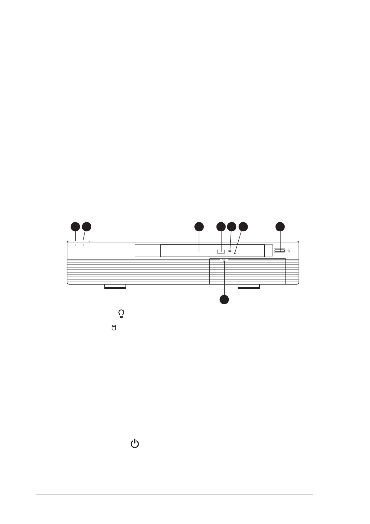
1.2 Front panel (external)
The front panel includes the power button, system LEDs, and the slim
optical drive.
11
1
11
1.1.
Power LED Power LED
1.
Power LED
1.1.
Power LED Power LED
2.2.
HDD LED HDD LED
2.
HDD LED
2.2.
HDD LED HDD LED
22
2
22
. .
. This LED lights up to indicate that the system is ON.
. .
. .
. This LED lights up when data is being read from or
. .
33
3
33
44
55
4
44
88
8
88
66
5
6
55
66
77
7
77
written to the hard disk drive.
3.3.
Optical driveOptical drive
3.
Optical drive. This is a slim optical disk drive.
3.3.
Optical driveOptical drive
4.4.
STOP/EJECT buttonSTOP/EJECT button
4.
STOP/EJECT button. Press this button to eject the disc loading tray.
4.4.
STOP/EJECT buttonSTOP/EJECT button
5.5.
Drive activity LEDDrive activity LED
5.
Drive activity LED. This LED lights up when you place a disc on the
5.5.
Drive activity LEDDrive activity LED
drive tray, and turns off when you remove the disc. The LED flashes
when data is being read from or written to the disc.
6.6.
Emergency eject pinholeEmergency eject pinhole
6.
Emergency eject pinhole. The emergency eject pinhole allows
6.6.
Emergency eject pinholeEmergency eject pinhole
you to manually eject a disc when the STOP button does not work due
to power failure or software problems. Insert the emergency eject pin
or a paper clip into this hole to manually eject the tray and the disc.
1-21-2
1-2
1-21-2
7.7.
Power button Power button
7.
Power button
7.7.
Power button Power button
8.8.
Front panel door lockFront panel door lock
8.
Front panel door lock. Press this lock to show the front panel I/O
8.8.
Front panel door lockFront panel door lock
. .
. Press this button to turn the system on.
. .
ports.
Chapter 1: System introductionChapter 1: System introduction
Chapter 1: System introduction
Chapter 1: System introductionChapter 1: System introduction
Page 13
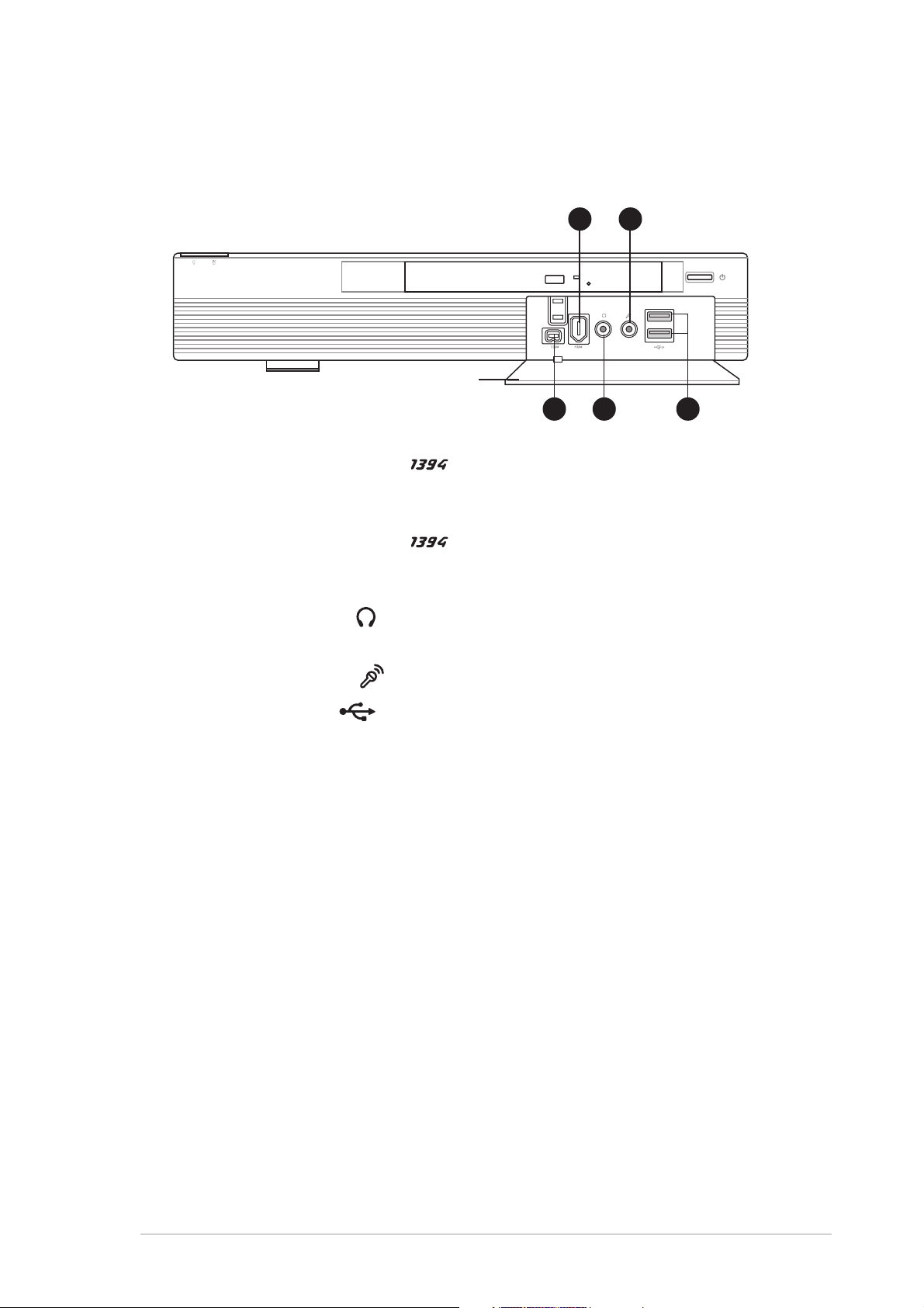
1.3 Front panel (internal)
The data and audio I/O ports are located inside the front panel door. Press
the front panel door lock to open.
Front panel doorFront panel door
Front panel door
Front panel doorFront panel door
9.9.
4-pin IEEE 1394 port 4-pin IEEE 1394 port
9.
4-pin IEEE 1394 port
9.9.
4-pin IEEE 1394 port 4-pin IEEE 1394 port
1010
10
1010
99
9
99
. .
. This port provides high-speed
. .
11
22
1
2
11
22
11
11
1
1
11
11
11
33
1
3
11
33
connectivity for IEEE 1394-compliant audio/video devices, storage
peripherals, and other PC devices.
10.10.
6-pin IEEE 1394 port 6-pin IEEE 1394 port
10.
6-pin IEEE 1394 port
10.10.
6-pin IEEE 1394 port 6-pin IEEE 1394 port
. This port provides high-speed
connectivity for IEEE 1394-compliant audio/video devices, storage
peripherals, and other PC devices.
11.11.
Headphone port Headphone port
11.
Headphone port
11.11.
Headphone port Headphone port
. .
. This port connects a headphone with a stereo
. .
mini-plug.
12.12.
Microphone port Microphone port
12.
Microphone port
12.12.
Microphone port Microphone port
13.13.
USB 2.0 ports USB 2.0 ports
13.
USB 2.0 ports
13.13.
USB 2.0 ports USB 2.0 ports
. .
. This Mic (pink) port connects a microphone.
. .
. .
. These Universal Serial Bus 2.0 (USB 2.0)
. .
ports are available for connecting USB 2.0 devices such as a mouse,
printer, scanner, camera, PDA, and others.
ASUS Pundit-PE2ASUS Pundit-PE2
ASUS Pundit-PE2
ASUS Pundit-PE2ASUS Pundit-PE2
1-31-3
1-3
1-31-3
Page 14
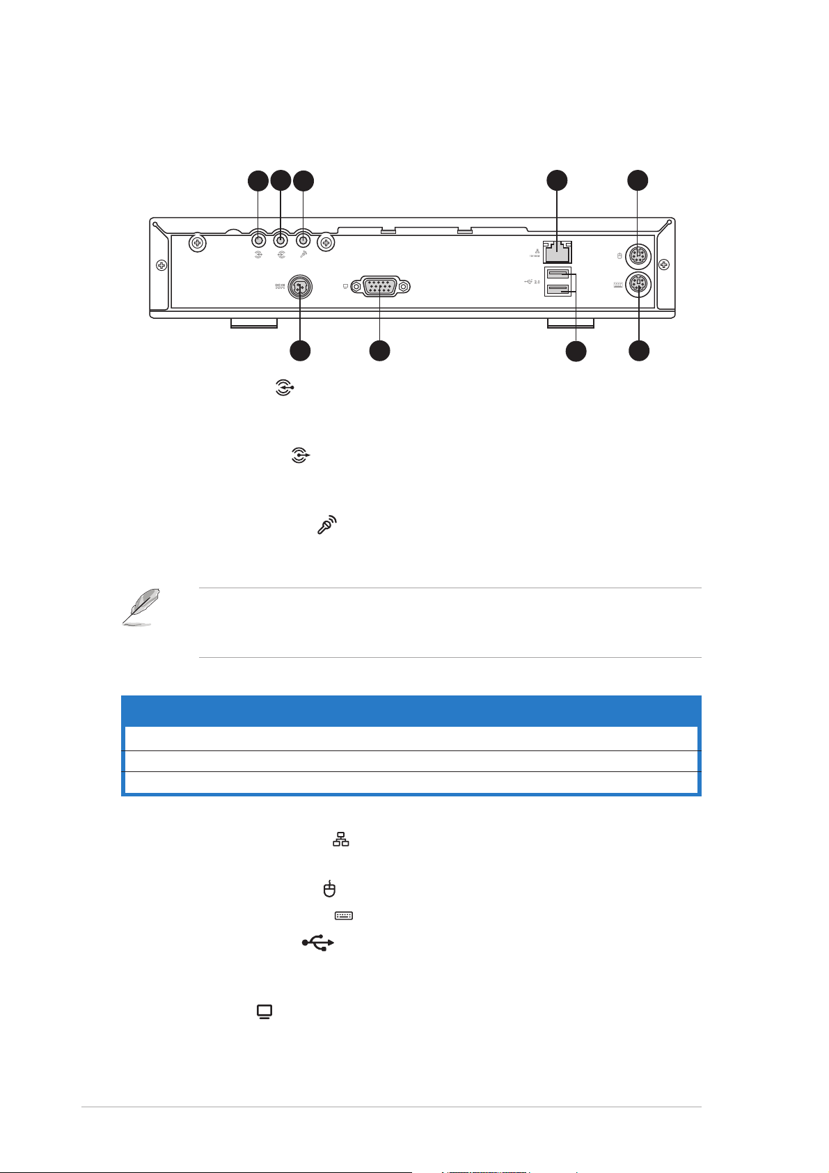
1.3 Rear panel
The system rear panel includes the power connector and several I/O ports
that allow convenient connection of devices.
1.1.
Line In port Line In port
1.
Line In port
1.1.
Line In port Line In port
44
4
11
1
11
33
22
3
2
33
22
99
9
99
. .
. This Line In (light blue) port connects a tape
. .
88
8
88
44
77
7
77
55
5
55
66
6
66
player or other audio sources. In 6-channel mode, the function of this
port becomes Low Frequency Enhanced Output/Center.
2.2.
Line Out port Line Out port
2.
Line Out port
2.2.
Line Out port Line Out port
. .
. This Line Out (lime) port connects a headphone
. .
or a speaker. In 4/6-channel mode, the function of this port becomes
Front Speaker Out.
3.3.
Microphone port Microphone port
3.
Microphone port
3.3.
Microphone port Microphone port
. .
. This Microphone (pink) port connects a
. .
microphone. In 4/6-channel mode, the function of this port becomes
Surround Speaker.
The functions of the Line Out, Line In, and Microphone ports change
when you select the 6-channel configuration. Refer to the table below
for audio ports function variation.
Audio ports function variationAudio ports function variation
Audio ports function variation
Audio ports function variationAudio ports function variation
PortPort
Port
PortPort
Light Blue Line In No function LFE Output*/Center
Lime Line Out Front Speaker Out Front Speaker Out
Pink Mic In Surround Surround
* Low Frequency Enhanced Output
4.4.
LAN (RJ-45) port LAN (RJ-45) port
4.
LAN (RJ-45) port
4.4.
LAN (RJ-45) port LAN (RJ-45) port
Headphone/2-ChannelHeadphone/2-Channel
Headphone/2-Channel
Headphone/2-ChannelHeadphone/2-Channel
. .
. This port allows Fast Ethernet connection to
. .
4-Channel4-Channel
4-Channel
4-Channel4-Channel
6-Channel6-Channel
6-Channel
6-Channel6-Channel
a Local Area Network (LAN) through a network hub.
55
..
PS/2 mouse port PS/2 mouse port
5
.
PS/2 mouse port
55
..
PS/2 mouse port PS/2 mouse port
6.6.
PS/2 keyboard port PS/2 keyboard port
6.
PS/2 keyboard port
6.6.
PS/2 keyboard port PS/2 keyboard port
7.7.
USB 2.0 ports USB 2.0 ports
7.
USB 2.0 ports
7.7.
USB 2.0 ports USB 2.0 ports
. This green 6-pin connector is for a PS/2 mouse.
. This purple 6-pin connector is for a PS/2 keyboard.
. .
. These Universal Serial Bus 2.0 (USB 2.0)
. .
ports are available for connecting USB 2.0 devices such as a mouse,
printer, scanner, camera, PDA, and others.
1-41-4
1-4
1-41-4
8.8.
VGA port VGA port
8.
VGA port
8.8.
VGA port VGA port
9.9.
Power connector.Power connector.
9.
Power connector. Connects the power plug is for the power cable
9.9.
Power connector.Power connector.
. .
. Connects a VGA monitor.
. .
and plug.
Chapter 1: System introductionChapter 1: System introduction
Chapter 1: System introduction
Chapter 1: System introductionChapter 1: System introduction
Page 15
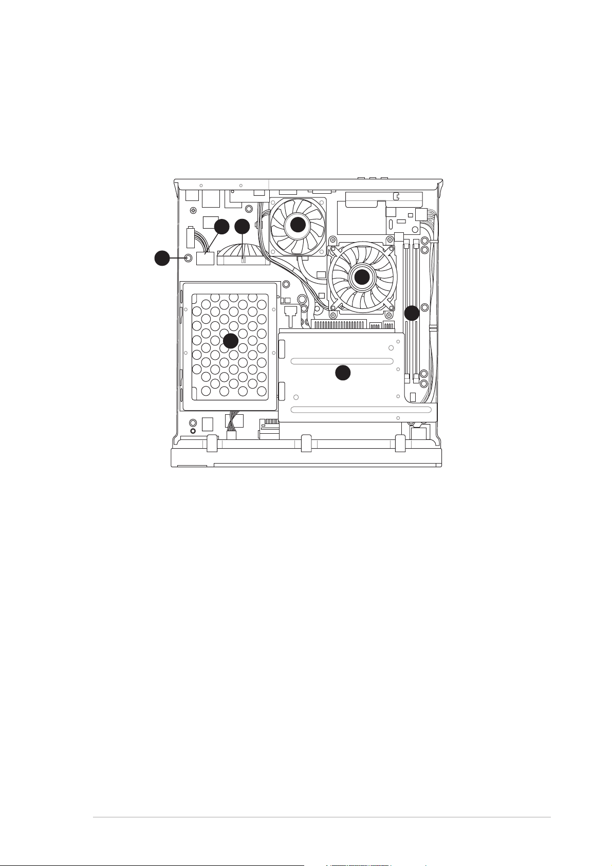
1.4 Internal components
The illustration below is the internal view of the system when you remove
the top cover. The installed components are labeled for your reference.
Proceed to Chapter 2 for instructions on installing other system
components.
44
4
33
3
22
33
2
22
11
1
11
77
7
77
44
55
5
55
66
6
66
88
8
88
1.1.
Standby power LEDStandby power LED
1.
Standby power LED
1.1.
Standby power LEDStandby power LED
2.2.
HDD power plug (to HDD power connector)HDD power plug (to HDD power connector)
2.
HDD power plug (to HDD power connector)
2.2.
HDD power plug (to HDD power connector)HDD power plug (to HDD power connector)
3.3.
IDE cable (to HDD connector)IDE cable (to HDD connector)
3.
IDE cable (to HDD connector)
3.3.
IDE cable (to HDD connector)IDE cable (to HDD connector)
4.4.
Chassis fanChassis fan
4.
Chassis fan
4.4.
Chassis fanChassis fan
5.5.
CPU fanCPU fan
5.
CPU fan
5.5.
CPU fanCPU fan
6.6.
DIMM socketsDIMM sockets
6.
DIMM sockets
6.6.
DIMM socketsDIMM sockets
7.7.
HDD metal trayHDD metal tray
7.
HDD metal tray
7.7.
HDD metal trayHDD metal tray
8.8.
Optical drive shieldOptical drive shield
8.
Optical drive shield
8.8.
Optical drive shieldOptical drive shield
ASUS Pundit-PE2ASUS Pundit-PE2
ASUS Pundit-PE2
ASUS Pundit-PE2ASUS Pundit-PE2
1-51-5
1-5
1-51-5
Page 16

1-61-6
1-6
1-61-6
Chapter 1: System introductionChapter 1: System introduction
Chapter 1: System introduction
Chapter 1: System introductionChapter 1: System introduction
Page 17

Chapter 2
This chapter provides step-by-step
instructions on how to install
components in the system.
ASUS Pundit-PE2ASUS Pundit-PE2
ASUS Pundit-PE2
ASUS Pundit-PE2ASUS Pundit-PE2
Basic installation
Page 18
2.1 Preparation
Before you proceed, make sure that you have all the components that you
plan to install in the Pundit-PE2 system.
Basic components to installBasic components to install
Basic components to install
Basic components to installBasic components to install
1. Hard disk drive (HDD)
2. Central processing unit (CPU)
3. DDR Dual Inline Memory Module (DIMM)
ToolTool
Tool
ToolTool
Phillips (cross) screw driver
2.2 Before you proceed
Take note of the following precautions before you install the system components.
• Unplug the AC adapter cable from the wall socket before touching
any component.
• Use a grounded wrist strap or touch a safely grounded object or to
a metal object, such as the power supply case, before handling
components to avoid damaging them due to static electricity.
• Hold components by the edges to avoid touching the ICs on them.
• Whenever you uninstall any component, place it on a grounded
antistatic pad or in the bag that came with the component.
Before you install or remove any component, ensureBefore you install or remove any component, ensure
•
Before you install or remove any component, ensure
Before you install or remove any component, ensureBefore you install or remove any component, ensure
that the system power supply is switched off or thethat the system power supply is switched off or the
that the system power supply is switched off or the
that the system power supply is switched off or thethat the system power supply is switched off or the
power cord is detached from the power supply. power cord is detached from the power supply.
power cord is detached from the power supply. Failure
power cord is detached from the power supply. power cord is detached from the power supply.
to do so may cause severe damage to the motherboard, peripherals,
and/or components.
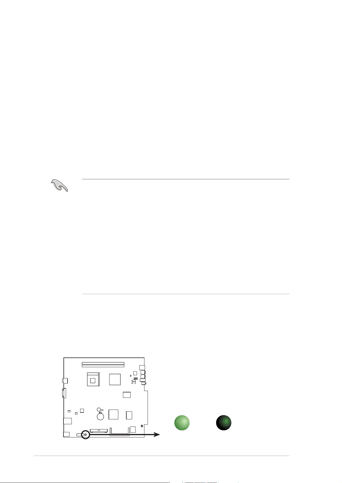
Onboard LEDOnboard LED
Onboard LED
Onboard LEDOnboard LED
The system motherboard comes with a standby power LED. The green LED
lights up to indicate that the system is ON, in sleep mode, or in soft-off
mode. This is a reminder that you should shut down the system and unplug
the AC adapter cable before removing or plugging in any system
component. The illustration below shows the location of the onboard LED.
2-22-2
2-2
2-22-2
Onboard LED
SBPWRLED
ON
Standby
Power
Chapter 2: Basic installationChapter 2: Basic installation
Chapter 2: Basic installation
Chapter 2: Basic installationChapter 2: Basic installation
OFF
Powered
Off
Page 19
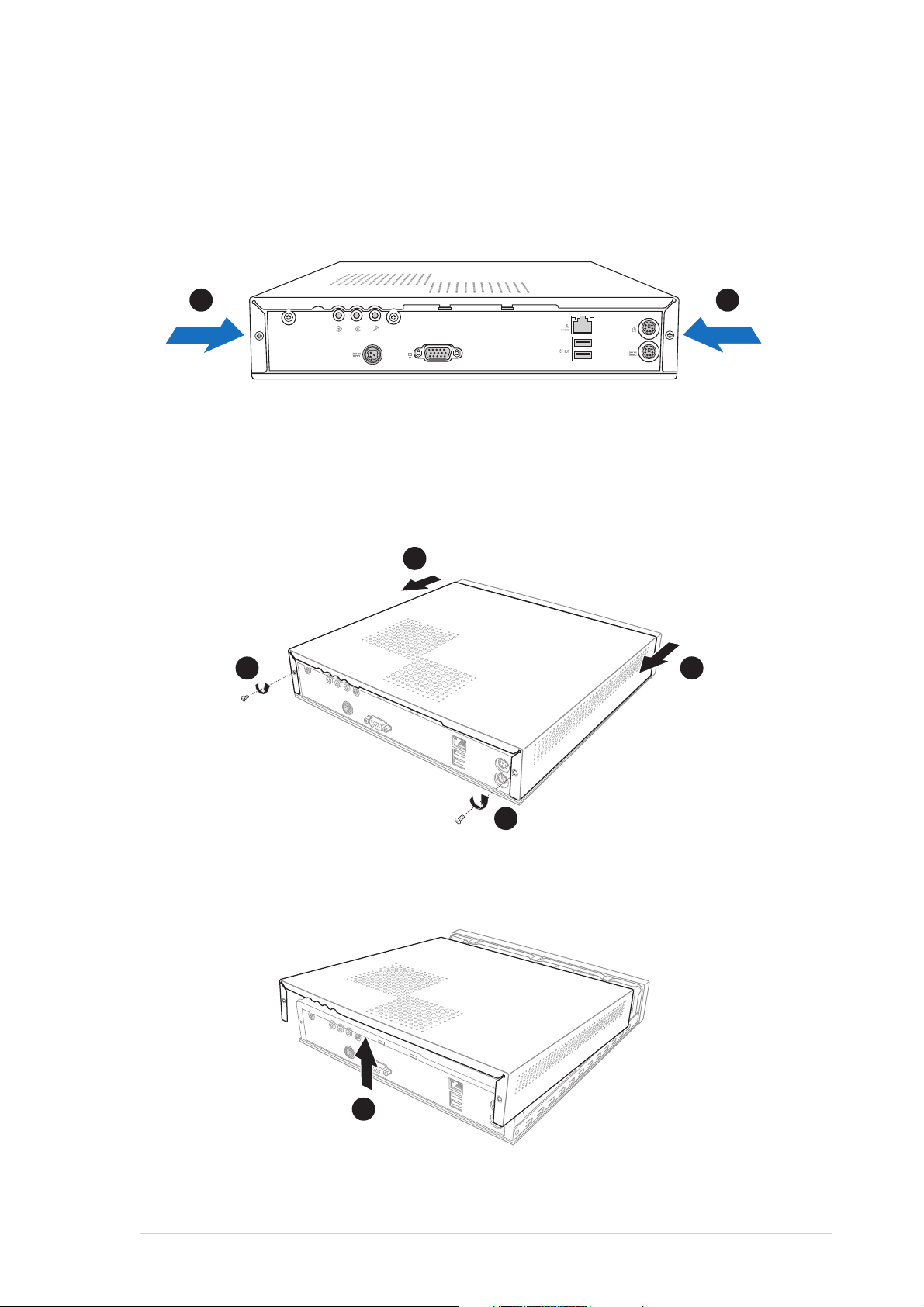
2.3 Removing the top cover
To remove the top cover:
1. On the rear panel, locate the two screws that secure the top cover to
the chassis.
11
1
11
11
1
11
2. Use a Phillips (cross) screw driver to remove the top cover screws.
Keep the screws for later use.
3. Pull the top cover slightly toward the rear panel until the side tabs are
disengaged from the chassis.
33
3
33
22
2
22
33
3
33
22
2
22
4. Hold the center edge of the top cover, then lift. Set the top cover
aside.
44
4
44
ASUS Pundit-PE2ASUS Pundit-PE2
ASUS Pundit-PE2
ASUS Pundit-PE2ASUS Pundit-PE2
2-32-3
2-3
2-32-3
Page 20
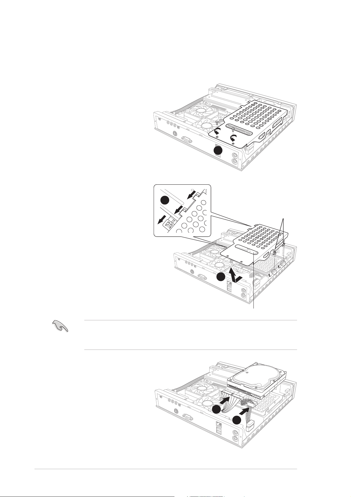
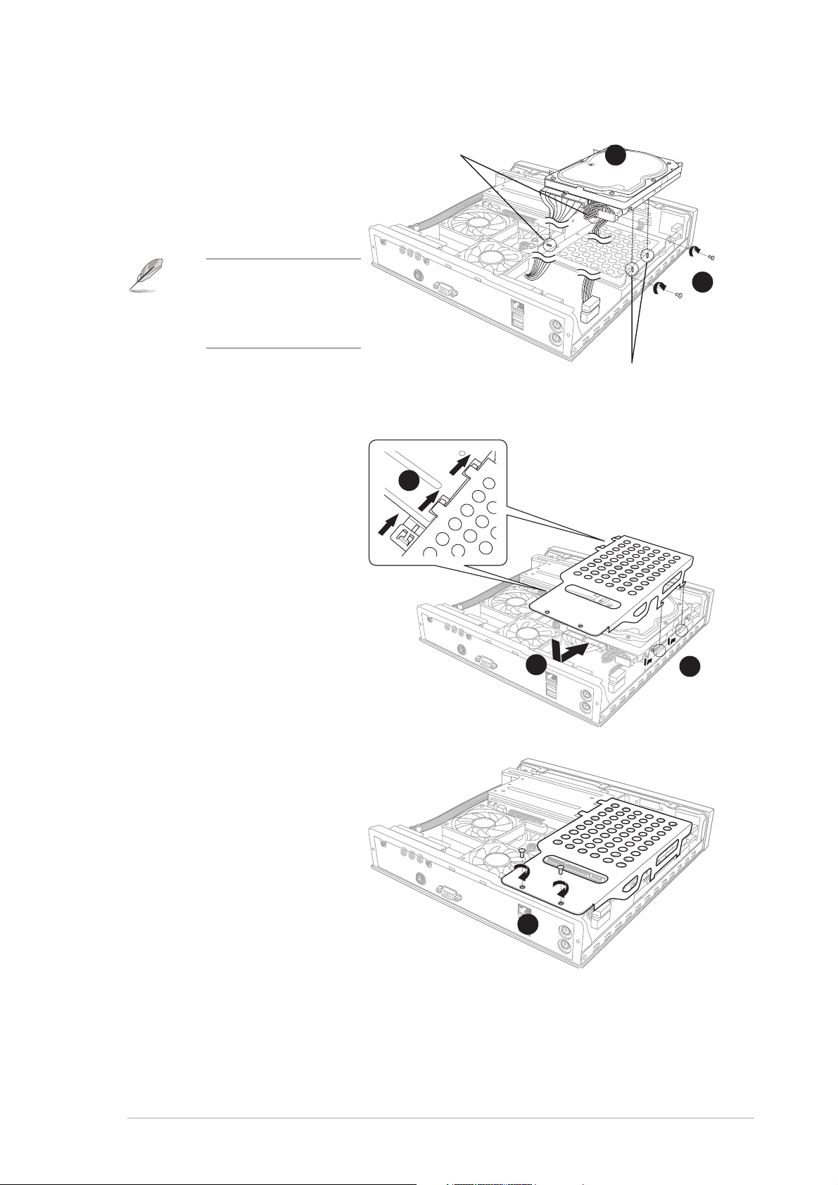
2.4 Installing a hard disk drive (HDD)
The Pundit-PE2 system supports one UltraATA133 IDE hard disk drive (HDD).
To install a hard disk drive:
1. Remove the two metal
cover screws. Keep the
screws for later use.
11
1
11
2. Use the metal cover
handle to slide the cover
toward the rear panel
until the side hooks
disengage from the HDD
metal tray and optical
drive shield tabs.
AA
A
AA
Side hooksSide hooks
Side hooks
Side hooksSide hooks
Side hooksSide hooks
Side hooks
Side hooksSide hooks
Lift the metal cover,
then set aside.
Set your hard disk drive as Master device before connecting the IDE
cable and power plug. Refer to the HDD documentation on how to set
the drive as Master device.
3. Connect the 40-pin IDE
cable to the IDE
connector on the drive.
4. Connect the 4-pin power
plug to the HDD power
connector.
BB
B
BB
HandleHandle
Handle
HandleHandle
33
3
33
44
4
44
2-42-4
2-4
2-42-4
Chapter 2: Basic installationChapter 2: Basic installation
Chapter 2: Basic installation
Chapter 2: Basic installationChapter 2: Basic installation
Page 21
5. Place the drive on the
tray. Insert the tray
metal tacks into the
drive screw holes (two
at the side and two at
the bottom).
Metal tacksMetal tacks
Metal tacks
Metal tacksMetal tacks
(To side of the drive)
55
5
55
Insert the side metal
tacks before
inserting the bottom
metal tacks.
6. Secure the drive with
two side screws.
7. Align the metal cover
side hooks with the HDD
metal tray and optical
drive shield tabs (A),
then slide the metal
cover toward the front
panel until it fits in place
(B).
AA
A
AA
Metal tacksMetal tacks
Metal tacks
Metal tacksMetal tacks
(To bottom of the drive)
BB
B
BB
AA
A
AA
66
6
66
8. Secure the metal cover
with screws that you
removed earlier.
ASUS Pundit-PE2ASUS Pundit-PE2
ASUS Pundit-PE2
ASUS Pundit-PE2ASUS Pundit-PE2
88
8
88
2-52-5
2-5
2-52-5
Page 22
2.5 Installing a CPU
The system motherboard has a surface mount 478-pin Zero Insertion Force
(ZIF) socket. This socket is specifically designed for the Intel
processor in the 478-pin package.
®
Pentium® 4
2.5.12.5.1
2.5.1
2.5.12.5.1
Removing the CPU fan and heatsink assemblyRemoving the CPU fan and heatsink assembly
Removing the CPU fan and heatsink assembly
Removing the CPU fan and heatsink assemblyRemoving the CPU fan and heatsink assembly
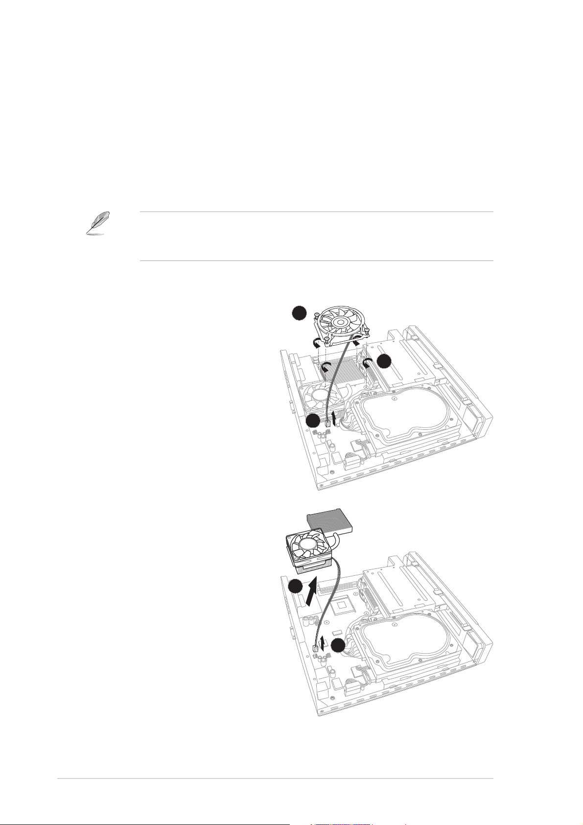
You must remove the CPU fan and heatsink assembly before you can install
a CPU.
The Pundit-PE2 system comes with a pre-installed proprietary CPU fan
and heatsink assembly for optimum CPU thermal control and system
ventilation. Do not replace the CPU fan with other models.
To remove the CPU fan and heatsink assembly:
1. Loosen the CPU fan screws.
33
3
33
2. Disconnect the CPU fan cable
from the CPU fan connector
on the motherboard.
11
1
11
3. Lift the CPU fan.
22
2
22
4. Disconnect the chassis fan
cable from the chassis fan
connector.
5. Move the chassis fan and
heatsink assembly toward
the direction of the front
panel, then lift.
Set the chassis fan and
heatsink assembly aside.
2-62-6
2-6
2-62-6
55
5
55
44
4
44
Chapter 2: Basic installationChapter 2: Basic installation
Chapter 2: Basic installation
Chapter 2: Basic installationChapter 2: Basic installation
Page 23

2.5.22.5.2
2.5.2
2.5.22.5.2
CPU installationCPU installation
CPU installation
CPU installationCPU installation
1. Locate the 478-pin CPU socket on the motherboard.
2. Unlock the socket by pressing the lever sideways then lifting it up to a
90° angle.
3. Position the CPU above the socket such that its marked corner (gold
mark) matches the base of the socket lever.
4. Carefully insert the CPU to the socket until it fits in place.
The CPU fits only in one correct orientation. Do not force the CPU into
the socket to prevent bending the pins and damaging the CPU!
33
3
33
11
1
11
CPUCPU
CPU
CPUCPU
˚
55
5
44
4
44
55
22
2
22
5. When the CPU is in place, push down the socket lever to secure the
CPU. The lever clicks on the side tab to indicate that it is locked.
ASUS Pundit-PE2ASUS Pundit-PE2
ASUS Pundit-PE2
ASUS Pundit-PE2ASUS Pundit-PE2
2-72-7
2-7
2-72-7
Page 24

2.5.32.5.3
2.5.3
2.5.32.5.3
Reinstalling the CPU fan and heatsinkReinstalling the CPU fan and heatsink
Reinstalling the CPU fan and heatsink
Reinstalling the CPU fan and heatsinkReinstalling the CPU fan and heatsink
assemblyassembly
assembly
assemblyassembly
To reinstall the CPU fan and heatsink assembly:
1. Place the chassis fan and
heatsink assembly on top of
the installed CPU. Make sure
that the CPU heatsink sits
properly on top of the CPU.
11
1
2. Connect the chassis fan
11
cable to the chassis fan
connector. See Chapter 4 for
22
2
the location of the chassis
22
fan connector.
3. Place the CPU fan over the
CPU heatsink, then fasten
the CPU fan screws to the
motherboard in a diagonal
pattern starting from two
opposite corner screws.
Do not overtighten the
CPU fan screws! Doing so
may damage the
motherboard.
4. Connect the CPU fan cable to
the CPU fan connector. See
Chapter 4 for the location of
the CPU fan connector.
33
3
33
44
4
44
2-82-8
2-8
2-82-8
Chapter 2: Basic installationChapter 2: Basic installation
Chapter 2: Basic installation
Chapter 2: Basic installationChapter 2: Basic installation
Page 25

2.6 Installing a DIMM
The system motherboard comes with two Double Data Rate (DDR) Dual
Inline Memory Module (DIMM) sockets. These sockets support up to 2 GB
system memory using unbuffered non-ECC PC2700/2100/1600 DIMMs.
To install a DDR DIMM:
1. Locate the two DIMM sockets
on the motherboard.
2. Unlock a socket by pressing
the retaining clips outward.
22
2
22
11
1
11
22
2
22
3. Align a DIMM on the socket
such that the notch on the
DIMM matches the break on
the socket.
33
3
33
a notch so that it fits in
only one direction. DO
NOT force a DIMM into a
socket to avoid damaging
the DIMM.
4. Firmly insert the DIMM into
the socket until the retaining
clips snap back in place and
the DIMM is properly seated.
3A DDR DIMM is keyed with
44
4
44
44
4
44
ASUS Pundit-PE2ASUS Pundit-PE2
ASUS Pundit-PE2
ASUS Pundit-PE2ASUS Pundit-PE2
2-92-9
2-9
2-92-9
Page 26

2.7 Replacing the top cover
Replace the top cover after installing the components.
To replace the top cover:
HooksHooks
Hooks
1. Position the front edge of
the top cover at least two
inches from the front panel
cover.
HooksHooks
22
2
22
2. Fit the top cover hooks with
the chassis side tabs and the
front panel cover tabs.
3. Lower the rear edge of the
top cover as shown.
4. Push the top cover slightly
toward the front panel until
it fits in place.
5. Secure the top cover with
two screws that you
removed earlier.
11
1
11
33
3
33
44
4
44
44
4
44
55
5
55
55
5
55
2-102-10
2-10
2-102-10
Chapter 2: Basic installationChapter 2: Basic installation
Chapter 2: Basic installation
Chapter 2: Basic installationChapter 2: Basic installation
Page 27

2.8 Connecting the power cable
The Pundit-PE2 system package includes a universal AC power adapter
(100V - 240V) with power cable and plug. The AC power adapter allows
you to use your system in any location regardless of the voltage output.
To connect the AC power adapter to the system:
1. Connect the power cable (female plug) to the AC power adapter.
2. Connect the other end of the power cable (male plug) to a power
outlet.
3. Check the AC power adapter LED. The LED lights up to indicate that
the power from the source is within the operating range.
4. Connect the DC IN power plug to the Pundit-PE2 DC IN socket.
DC IN power plugDC IN power plug
DC IN power plug
DC IN power plugDC IN power plug
Use an outlet adapter if the power plug does not fit the power outlet in
your area.
44
4
44
33
3
33
Power LEDPower LED
Power LED
Power LEDPower LED
11
1
11
Power adapterPower adapter
Power adapter
Power adapterPower adapter
22
2
22
Power cablePower cable
Power cable
Power cablePower cable
ASUS Pundit-PE2ASUS Pundit-PE2
ASUS Pundit-PE2
ASUS Pundit-PE2ASUS Pundit-PE2
2-112-11
2-11
2-112-11
Page 28

2.9 Connecting external devices
To the front panelTo the front panel
To the front panel
To the front panelTo the front panel
To the rear panelTo the rear panel
To the rear panel
To the rear panelTo the rear panel
CameraCamera
Camera
CameraCamera
HDDHDD
HDD
HDDHDD
HeadphoneHeadphone
Headphone
HeadphoneHeadphone
MicMic
Mic
MicMic
ScannerScanner
Scanner
ScannerScanner
Line InLine In
Line In
Line InLine In
Line OutLine Out
Line Out
Line OutLine Out
MicMic
Mic
MicMic
VGA MonitorVGA Monitor
VGA Monitor
VGA MonitorVGA Monitor
Hub or RouterHub or Router
Hub or Router
Hub or RouterHub or Router
USB MouseUSB Mouse
USB Mouse
USB MouseUSB Mouse
PS/2 MousePS/2 Mouse
PS/2 Mouse
PS/2 MousePS/2 Mouse
PS/2 KBPS/2 KB
PS/2 KB
PS/2 KBPS/2 KB
2-122-12
2-12
2-122-12
Chapter 2: Basic installationChapter 2: Basic installation
Chapter 2: Basic installation
Chapter 2: Basic installationChapter 2: Basic installation
Page 29

Chapter 3
This chapter helps you power up
the system and install drivers and
utilities from the support CD.
ASUS Pundit-PE2ASUS Pundit-PE2
ASUS Pundit-PE2
ASUS Pundit-PE2ASUS Pundit-PE2
Getting started
Page 30

3.1 Installing an operating system
This system supports Windows® 2000/XP operating systems (OS). Always
install the latest OS version and corresponding updates to maximize the
features of your system.
• Motherboard settings and hardware options vary. Use the setup
procedures presented in this chapter for reference only. Refer to
your OS documentation for detailed information.
®
• Make sure that you install Windows
Windows® XP Service Pack 1 or later versions before installing the
drivers for better compatibility and system stability.
2000 Service Pack 4 or the
3.2 Support CD information
The support CD that came with the system package contains the drivers,
software applications, and utilities that you can install to avail all system
features.
The contents of the support CD are subject to change at any time
without notice. Visit the ASUS website(www.asus.com) for updates.
3.2.13.2.1
3.2.1
3.2.13.2.1
Running the support CDRunning the support CD
Running the support CD
Running the support CDRunning the support CD
Place the support CD to the optical drive. The CD automatically displays the
Drivers Drivers
Dr i v e r s menu if Autorun is enabled in your computer.
Drivers Drivers
Click an icon toClick an icon to
Click an icon to
Click an icon toClick an icon to
display supportdisplay support
display support
display supportdisplay support
CD/motherboardCD/motherboard
CD/motherboard
CD/motherboardCD/motherboard
informationinformation
information
informationinformation
Click an item to installClick an item to install
Click an item to install
Click an item to installClick an item to install
3-23-2
3-2
3-23-2
Autorun Autorun
If
Autorun is NOT enabled in your computer, browse the contents of
Autorun Autorun
the support CD to locate the file ASSETUP.EXE from the BIN folder.
Double-click the
ASSETUP.EXEASSETUP.EXE
ASSETUP.EXE to run the CD.
ASSETUP.EXEASSETUP.EXE
Chapter 3: Getting startedChapter 3: Getting started
Chapter 3: Getting started
Chapter 3: Getting startedChapter 3: Getting started
Page 31

3.2.23.2.2
3.2.2
3.2.23.2.2
The drivers menu shows the available device drivers if the system detects
installed devices. Install the necessary drivers to activate the devices.
Drivers menuDrivers menu
Drivers menu
Drivers menuDrivers menu
SiS 651 Display DriverSiS 651 Display Driver
SiS 651 Display Driver
SiS 651 Display DriverSiS 651 Display Driver
Installs the SiS 651 display driver.
®®
®
AD1980 SoundMAXAD1980 SoundMAX
AD1980 SoundMAX
AD1980 SoundMAXAD1980 SoundMAX
Installs the AD1980 audio driver and the SoundMax
3-1X for details.
SiS PCI LAN DriverSiS PCI LAN Driver
SiS PCI LAN Driver
SiS PCI LAN DriverSiS PCI LAN Driver
Installs the SiS PCI LAN driver.
SiS Mini IDE DriverSiS Mini IDE Driver
SiS Mini IDE Driver
SiS Mini IDE DriverSiS Mini IDE Driver
Installs the SiS Mini IDE driver.
USB 2.0 DriverUSB 2.0 Driver
USB 2.0 Driver
USB 2.0 DriverUSB 2.0 Driver
Installs the USB 2.0 driver.
The screen display and drivers option may not be the same for different
operating system versions.
®®
Audio Driver Audio Driver
Audio Driver
Audio Driver Audio Driver
®
application. See page
ASUS Pundit-PE2ASUS Pundit-PE2
ASUS Pundit-PE2
ASUS Pundit-PE2ASUS Pundit-PE2
3-33-3
3-3
3-33-3
Page 32

3.2.33.2.3
3.2.3
3.2.33.2.3
The Utilities menu shows the applications and other software that the
motherboard supports.
ASUS PC ProbeASUS PC Probe
ASUS PC Probe
ASUS PC ProbeASUS PC Probe
Utilities menuUtilities menu
Utilities menu
Utilities menuUtilities menu
This smart utility monitors the fan speed, CPU temperature, and system
voltages, and alerts you of any detected problems. This utility helps you
keep your computer in healthy operating condition.
ASUS UpdateASUS Update
ASUS Update
ASUS UpdateASUS Update
The ASUS Update utility allows you to update the motherboard BIOS in a
Windows® environment. This utility requires an Internet connection either
through a network or an Internet Service Provider (ISP). See page 5-XX for
details.
Anti-Virus UtilityAnti-Virus Utility
Anti-Virus Utility
Anti-Virus UtilityAnti-Virus Utility
The anti-virus application scans, identifies, and removes computer viruses.
View the online help for detailed information.
Microsoft DirectX 9.0cMicrosoft DirectX 9.0c
Microsoft DirectX 9.0c
Microsoft DirectX 9.0cMicrosoft DirectX 9.0c
Installs the Microsoft® DirectX 9.0c driver.
ADOBE Acrobat ReaderADOBE Acrobat Reader
ADOBE Acrobat Reader
ADOBE Acrobat ReaderADOBE Acrobat Reader
Installs the Adobe® Acrobat® Reader V5.0.
ASUS Screen SaverASUS Screen Saver
ASUS Screen Saver
ASUS Screen SaverASUS Screen Saver
Installs the ASUS screen saver.
The screen display and utilities option may not be the same for different
operating system versions.
3-43-4
3-4
3-43-4
Chapter 3: Getting startedChapter 3: Getting started
Chapter 3: Getting started
Chapter 3: Getting startedChapter 3: Getting started
Page 33

3.2.43.2.4
3.2.4
3.2.43.2.4
ASUS contact informationASUS contact information
ASUS contact information
ASUS contact informationASUS contact information
Click the
also find this information on the inside front cover of this user guide.
Contact Contact
Contact tab to display the ASUS contact information. You can
Contact Contact
3.2.53.2.5
3.2.5
3.2.53.2.5
The icons on the top right corner of the screen give additional information
on the motherboard and the contents of the support CD. Click an icon to
display the specified information.
Other informationOther information
Other information
Other informationOther information
ASUS Pundit-PE2ASUS Pundit-PE2
ASUS Pundit-PE2
ASUS Pundit-PE2ASUS Pundit-PE2
3-53-5
3-5
3-53-5
Page 34

3.3 Software information
Multi-channel audio featureMulti-channel audio feature
Multi-channel audio feature
Multi-channel audio featureMulti-channel audio feature
The AD1980 AC ‘97 audio CODEC provides 6-channel audio capability to
your system.
Setting the multi-channel audioSetting the multi-channel audio
Setting the multi-channel audio
Setting the multi-channel audioSetting the multi-channel audio
To set the multi-channel audio:
1. Connect the speakers (4-channel/6-channel) to the audio I/O ports on
the system rear panel. Refer to the
variation variation
variation table on page 1-4.
variation variation
2. Install the AD1980 SoundMAX Audio Driver from the support CD.
Refer to page 3-3 for details.
3. After installing the driver, the
SoundMAX icon appears on the
taskbar. Double-click the icon to
display the SoundMAX Control
Panel.
Audio ports functionAudio ports function
Audio ports function
Audio ports functionAudio ports function
4. From the
option, click
Surround Sound SpeakersSurround Sound Speakers
Surround Sound Speakers
Surround Sound SpeakersSurround Sound Speakers
(5.1 Surround)(5.1 Surround)
(5.1 Surround) from the
(5.1 Surround)(5.1 Surround)
drop-down list box.
5. Click
Testing the multi-channel audioTesting the multi-channel audio
Testing the multi-channel audio
Testing the multi-channel audioTesting the multi-channel audio
To test the multi-channel audio:
1. Click the
Test ListeningTest Listening
the
Test Listening
Test ListeningTest Listening
Environment Environment
Environment window.
Environment Environment
Speaker SetupSpeaker Setup
Speaker Setup
Speaker SetupSpeaker Setup
, then select
ApplyApply
Apply.
ApplyApply
Listening Environment Listening Environment
The
Listening Environment tab also allows you to enable or disable
Listening Environment Listening Environment
the Virtual Theater Surround and select Acoustic Environments and
Virtual Ear.
Test Test
Test button to display
Test Test
3-63-6
3-6
3-63-6
Chapter 3: Getting startedChapter 3: Getting started
Chapter 3: Getting started
Chapter 3: Getting startedChapter 3: Getting started
Page 35

2. Select an audio test path, then
click the
Play Test NoisePlay Test Noise
Play Test Noise
Play Test NoisePlay Test Noise
button to test the speakers.
Audio pathAudio path
Audio path
Audio pathAudio path
indicatorindicator
indicator
indicatorindicator
While testing, the audio path
indicator (black circle) moves
from one speaker to another
based on your specified audio
test path.
While testing, the
PlayingPlaying
Playing. Click this button any time to stop testing.
PlayingPlaying
3. Click the
Configuring the MIDI settingsConfiguring the MIDI settings
Configuring the MIDI settings
Configuring the MIDI settingsConfiguring the MIDI settings
CloseClose
Close button when done.
CloseClose
Play Test Noise Play Test Noise
Play Test Noise button becomes toggles to
Play Test Noise Play Test Noise
To configure the MIDI settings:
1. Click the
SynthesizerSynthesizer
Synthesizer tab.
SynthesizerSynthesizer
2. From the
option, click
MIDI MusicMIDI Music
MIDI Music
MIDI MusicMIDI Music
Choose Default SetChoose Default Set
Choose Default Set
Choose Default SetChoose Default Set
, then select the
default synthesizer setting from
the drop-down list box.
3. Click
OK OK
O K when finished, then
OK OK
restart the computer.
StopStop
Stop
StopStop
ASUS Pundit-PE2ASUS Pundit-PE2
ASUS Pundit-PE2
ASUS Pundit-PE2ASUS Pundit-PE2
3-73-7
3-7
3-73-7
Page 36

Enabling the SPDIF optionsEnabling the SPDIF options
Enabling the SPDIF options
Enabling the SPDIF optionsEnabling the SPDIF options
To enable the SPDIF options:
1. After restart, click on the volume
control icon on the taskbar to display
Volume ControlVolume Control
the
Volume Control window.
Volume ControlVolume Control
2. Click the Volume Control
AdvancedAdvanced
Advanced
AdvancedAdvanced
button.
3. Check the options
PCM SPDIF PCM SPDIF
PCM SPDIF to achieve 6-channel audio
PCM SPDIF PCM SPDIF
AC3 SPDIFAC3 SPDIF
AC3 SPDIF and
AC3 SPDIFAC3 SPDIF
capability when playing DVDs.
4. Click
Enabling the front panel microphone portEnabling the front panel microphone port
Enabling the front panel microphone port
Enabling the front panel microphone portEnabling the front panel microphone port
Close Close
Close when finished.
Close Close
To enable the front panel microphone port:
1. Click the Microphone
button to display the
Controls for MicrophoneControls for Microphone
Controls for Microphone window.
Controls for MicrophoneControls for Microphone
2. Check the box before the
AdvancedAdvanced
Advanced
AdvancedAdvanced
AdvancedAdvanced
Advanced
AdvancedAdvanced
Mic2 SelectMic2 Select
Mic2 Select
Mic2 SelectMic2 Select
option to enable the front panel
microphone port.
3-83-8
3-8
3-83-8
3. Click
CloseClose
Close.
CloseClose
The rear panel Mic port (pink) is automatically disabled when you enable
the front panel Mic port. Only one Mic port works at a time.
Chapter 3: Getting startedChapter 3: Getting started
Chapter 3: Getting started
Chapter 3: Getting startedChapter 3: Getting started
Page 37

Chapter 4
This chapter gives information
about the motherboard that comes
with the system. This chapter
includes the motherboard layout,
jumper settings, and connector
locations.
ASUS Pundit-PE2ASUS Pundit-PE2
ASUS Pundit-PE2
ASUS Pundit-PE2ASUS Pundit-PE2
Motherboard info
Page 38

4.1 Motherboard overview
Motherboard layoutMotherboard layout
Motherboard layout
Motherboard layoutMotherboard layout
27.2cm (10.7in)
DDR DIMM2 (64/72-bit, 184-pin module)
DDR DIMM1 (64/72-bit, 184-pin module)
Socket 478
SiS 651
Host
Memory
ADAPTER
Controller
VT6307
PWRSW
VIA
AUD_CON
CD
AUX
AD1980
USB34
IE1394_1
FONT
MIC
FONT
LOUT
IE1394_2
26.9cm (10.6in)
LAN_USB78
PS/2
T:Mouse
B:Keyboard
CHA_FAN
CPU_FAN
8201BL
IDEPWR
BUZZER
RTL
SBPWRLED
CR2032 3V
Lithium Cell
CMOS Power
CLRTC
PRI_IDE
SiS
962L
UA
PCI1
Super
I/O
4 Mb
ISA
LED_CON
4-24-2
4-2
4-24-2
Chapter 4: Motherboard infoChapter 4: Motherboard info
Chapter 4: Motherboard info
Chapter 4: Motherboard infoChapter 4: Motherboard info
Page 39

4.2 Jumper
Clear RTC RAM (CLRTC)Clear RTC RAM (CLRTC)
Clear RTC RAM (CLRTC)
Clear RTC RAM (CLRTC)Clear RTC RAM (CLRTC)
This jumper allows you to clear the Real Time Clock (RTC) RAM in CMOS.
You can clear the CMOS memory of date, time, and system setup
parameters by erasing the CMOS RTC RAM data. The onboard button cell
battery powers the RAM data in CMOS, which include system setup
information such as system passwords.
To erase the RTC RAM:
1. Turn OFF the computer and unplug the power cord.
2. Remove the onboard battery.
3. Move the jumper cap from pins 1-2 (default) to pins 2-3. Keep the
cap on pins 2-3 for about 5~10 seconds, then move the cap back to
pins 1-2.
4. Reinstall the battery.
5. Plug the power cord and turn ON the computer.
6. Hold down the <Del> key during the boot process and enter BIOS
setup to re-enter data.
Except when clearing the RTC RAM, never remove the cap on CLRTC
jumper default position. Removing the cap will cause system boot failure!
Clear RTC RAM
Normal
(Default)
CLRTC
2312
Clear CMOS
ASUS Pundit-PE2ASUS Pundit-PE2
ASUS Pundit-PE2
ASUS Pundit-PE2ASUS Pundit-PE2
4-34-3
4-3
4-34-3
Page 40

4.3 Connectors
4.3.14.3.1
4.3.1
4.3.14.3.1
Refer to section “1.3 Rear panel” for a description of the rear panel I/O ports.
4.3.24.3.2
4.3.2
4.3.24.3.2
1.1.
Primary IDE connector (40-1 pin PRI_IDE)Primary IDE connector (40-1 pin PRI_IDE)
1.
Primary IDE connector (40-1 pin PRI_IDE)
1.1.
Primary IDE connector (40-1 pin PRI_IDE)Primary IDE connector (40-1 pin PRI_IDE)
This connector is for an Ultra DMA 100/66 signal cable. The Ultra
DMA 100/66 signal cable has three connectors: a blue connector for
the primary IDE connector on the motherboard, a black connector for
an Ultra DMA 100/66 IDE slave device (optical drive/hard disk drive),
and a gray connector for an Ultra DMA 100/66 IDE master device (hard
disk drive). If you install two hard disk drives, you must configure the
second drive as a slave device by setting its jumper accordingly. Refer
to the hard disk documentation for the jumper settings.
Rear panel connectorsRear panel connectors
Rear panel connectors
Rear panel connectorsRear panel connectors
Internal connectorsInternal connectors
Internal connectors
Internal connectorsInternal connectors
• Pin 20 on the IDE connector is removed to match the covered hole
on the Ultra DMA cable connector. This prevents incorrect insertion
when you connect the IDE cable.
• Use the 80-conductor IDE cable for Ultra DMA 100/66 IDE devices.
IDE connector
PRI_IDE
PIN 1
NOTE: Orient the red markings
(usually zigzag) on the IDE
ribbon cable to PIN 1.
4-44-4
4-4
4-44-4
Chapter 4: Motherboard infoChapter 4: Motherboard info
Chapter 4: Motherboard info
Chapter 4: Motherboard infoChapter 4: Motherboard info
Page 41

2.2.
CPU and Chassis Fan connectors (3-pin CPU_FAN, CHA_FAN)CPU and Chassis Fan connectors (3-pin CPU_FAN, CHA_FAN)
2.
CPU and Chassis Fan connectors (3-pin CPU_FAN, CHA_FAN)
2.2.
CPU and Chassis Fan connectors (3-pin CPU_FAN, CHA_FAN)CPU and Chassis Fan connectors (3-pin CPU_FAN, CHA_FAN)
The fan connectors support cooling fans of 350 mA~740 mA (8.88 W
max.) or a total of 1 A~2.22 A (26.64 W max.) at +12V. Connect the
fan cables to the fan connectors on the motherboard, making sure that
the black wire of each cable matches the ground pin of the connector.
Do not forget to connect the fan cables to the fan connectors.
Insufficient air flow inside the system may damage the motherboard
components. These are not jumpers! Do not place jumper caps on the
fan connectors!
CHA_FAN CPU_FAN
GND
+12V
Rotation
GND
+12V
Rotation
Fan connectors
3.3.
Internal audio connectors (4-pin CD1, AUX1)Internal audio connectors (4-pin CD1, AUX1)
3.
Internal audio connectors (4-pin CD1, AUX1)
3.3.
Internal audio connectors (4-pin CD1, AUX1)Internal audio connectors (4-pin CD1, AUX1)
These connectors allow you to receive stereo audio input from audio
sources such as an optical drive, TV tuner, or MPEG card.
Ground
Ground
Left Audio Channel
Right Audio Channel
CD (Black)
AUX (White)
Internal audio connectors
Enable the CD-IN function in the audio utility when using these
connectors.
ASUS Pundit-PE2ASUS Pundit-PE2
ASUS Pundit-PE2
ASUS Pundit-PE2ASUS Pundit-PE2
4-54-5
4-5
4-54-5
Page 42

4.4.
IDE power connector (4-pin IDEPWR)IDE power connector (4-pin IDEPWR)
4.
IDE power connector (4-pin IDEPWR)
4.4.
IDE power connector (4-pin IDEPWR)IDE power connector (4-pin IDEPWR)
The IDE power connector is for the IDE power cable. This connector
supplies power to the hard disk drive and the slim optical drive.
IDEPWR
IDE power connector
5.5.
Power switch connector (2-pin PWRSW)Power switch connector (2-pin PWRSW)
5.
Power switch connector (2-pin PWRSW)
5.5.
Power switch connector (2-pin PWRSW)Power switch connector (2-pin PWRSW)
+5V
GND
GND
+12V
This connects to the the system power switch button on the system
front panel.
PWRSW
Power switch connector
4-64-6
4-6
4-64-6
Chapter 4: Motherboard infoChapter 4: Motherboard info
Chapter 4: Motherboard info
Chapter 4: Motherboard infoChapter 4: Motherboard info
Page 43

6.6.
Rear panel audio connectors (10-1 pin AUD_CON)Rear panel audio connectors (10-1 pin AUD_CON)
6.
Rear panel audio connectors (10-1 pin AUD_CON)
6.6.
Rear panel audio connectors (10-1 pin AUD_CON)Rear panel audio connectors (10-1 pin AUD_CON)
This connector is for the ASUS proprietary rear panel audio board that
supports the rear panel audio I/O ports.
SURR_RLOUT_L
GND
+5V
VREFOUT
SURR_L
1
AUD_CON
LOUT_R
LINE_IN_LT
LINE_IN_RT
Rear panel audio connector
7.7.
Front panel LED connector (6-pin LED_CON)Front panel LED connector (6-pin LED_CON)
7.
Front panel LED connector (6-pin LED_CON)
7.7.
Front panel LED connector (6-pin LED_CON)Front panel LED connector (6-pin LED_CON)
The connector is for the power and HDD activity LED in the system
front panel.
Front panel LED connector
LED_CON
HDD LED
Power LED
1
ASUS Pundit-PE2ASUS Pundit-PE2
ASUS Pundit-PE2
ASUS Pundit-PE2ASUS Pundit-PE2
4-74-7
4-7
4-74-7
Page 44

4-84-8
4-8
4-84-8
Chapter 4: Motherboard infoChapter 4: Motherboard info
Chapter 4: Motherboard info
Chapter 4: Motherboard infoChapter 4: Motherboard info
Page 45

Chapter 5
This chapter tells how to change
system settings through the BIOS
Setup menus and describes the
BIOS parameters.
ASUS Pundit-PE2ASUS Pundit-PE2
ASUS Pundit-PE2
ASUS Pundit-PE2ASUS Pundit-PE2
BIOS setup
Page 46

5.1 Managing and updating your BIOS
The following utilities allow you to manage and update the motherboard
Basic Input/Output System (BIOS) setup.
ASUS EZFlash ASUS EZFlash
1.
ASUS EZFlash (Updates the BIOS in DOS mode using a USB floppy
ASUS EZFlash ASUS EZFlash
disk or memory card.)
ASUS CrashFree BIOS ASUS CrashFree BIOS
2.
ASUS CrashFree BIOS (Updates the BIOS using the motherboard
ASUS CrashFree BIOS ASUS CrashFree BIOS
support CD when the BIOS file fails or gets corrupted.)
ASUS Update ASUS Update
3.
ASUS Update (Updates the BIOS in Windows
ASUS Update ASUS Update
Refer to the corresponding sections for details on these utilities.
®
environment.)
5.1.15.1.1
5.1.1
5.1.15.1.1
ASUS EZ FlashASUS EZ Flash
ASUS EZ Flash
ASUS EZ FlashASUS EZ Flash
To update the BIOS file using ASUS EZ Flash:
1. Download the latest BIOS file from the ASUS website (www.asus.com),
then save the file to a floppy disk or a USB flash disk.
Write down the BIOS file name on a piece of paper. You need to type the
exact BIOS file nameexact BIOS file name
exact BIOS file name at the EZ Flash screen.
exact BIOS file nameexact BIOS file name
2. Restart the system.
3. During POST, press <Alt> + <F2> to display the ASUS EZ Flash screen.
ASUS EZ Flash V1.00
Copyright (C) 2002, ASUSTeK COMPUTER INC.
[Onboard BIOS Information]
BIOS Version : ASUS P4SQ-X ACPI BIOS Revision 1002
BIOS Model : P4SQ-X
BIOS Built Date : 01/20/05
Please Enter File Name for NEW BIOS: _
*Note: EZ Flash will copy file from A:\, Press [ESC] to reboot
The BIOS information in the above screen is for reference only. What you
see on your screen may not be exactly the same as shown.
4. Insert the flash disk/floppy disk that contains the new BIOS file to a
USB port/USB floppy disk drive. The display shows, “WARNING! Device
not ready.” if you proceed to step 5 without the flash disk/floppy disk
in the USB port/USB floppy drive.
5. At the “Please Enter File Name for NEW BIOS: _” prompt, type the file
name of the updated BIOS file, then press <Enter>.
The application automatically searches the USB flash disk/floppy disk
for the updated BIOS file.
5-25-2
5-2
5-25-2
Chapter 5: BIOS setupChapter 5: BIOS setup
Chapter 5: BIOS setup
Chapter 5: BIOS setupChapter 5: BIOS setup
Page 47

If you accidentally typed in a wrong BIOS file name, a
not found.”not found.”
not found.” message appears. Press <Enter> to close the message,
not found.”not found.”
type the correct BIOS file name, then press <Enter>.
“ WARNING! File“WARNING! File
“ WARNING! File
“ WARNING! File“WARNING! File
When the updated BIOS file is found, the following message appears
on screen.
[BIOS Information in File]
BIOS Version: P4SQ-X Boot Block
WARNING! Continue to update the BIOS (Y/N)? _
6. Press <Y> to continue updating the BIOS file.
7. When prompted, press <Y> to update the main BIOS area.
Flash Memory: SST 49LF004
Update Main BIOS area (Y/N)? _
DO NOT shutdown or reset the system while updating the BIOS area!
Doing so may cause system boot failure.
8. When the update process is finished, press any key to restart the
system.
ASUS Pundit-PE2ASUS Pundit-PE2
ASUS Pundit-PE2
ASUS Pundit-PE2ASUS Pundit-PE2
5-35-3
5-3
5-35-3
Page 48

5.1.25.1.2
5.1.2
5.1.25.1.2
ASUS CrashFree BIOS utilityASUS CrashFree BIOS utility
ASUS CrashFree BIOS utility
ASUS CrashFree BIOS utilityASUS CrashFree BIOS utility
The ASUS CrashFree BIOS is an auto recovery tool that allows you to restore
or update the BIOS file when it fails or gets corrupted during the updating
process. You can restore or update a corrupted BIOS file using the system
support CD.
Prepare the system support CD containing the original or updated BIOS
file before using this utility.
To recover the BIOS using the ASUS CrashFree BIOS Utility:
1. Turn on the system.
2. Place the support CD to the optical drive.
3. The utility displays the following message and automatically checks
the motherboard support CD for the original/updated BIOS file.
Bad BIOS checksum. Starting BIOS recovery...
Checking for floppy...
Floppy not found!
Checking for CD-ROM...
CD-ROM found!
Reading file “P4SQ-X.BIN”. Completed.
Start flashing...
When the original/updated BIOS file is found, the utility automatically
updates the corrupted BIOS file.
DO NOT shut down or reset the system while updating the BIOS! Doing
so can cause system boot failure!
The utility restarts the system after the updating process.
The recovered BIOS file may not be the updated BIOS for this system.
Visit the ASUS website (www.asus.com) to download the latest BIOS file.
5-45-4
5-4
5-45-4
Chapter 5: BIOS setupChapter 5: BIOS setup
Chapter 5: BIOS setup
Chapter 5: BIOS setupChapter 5: BIOS setup
Page 49

5.1.35.1.3
5.1.3
5.1.35.1.3
The ASUS Update is a utility that allows you to manage, save, and update
the system BIOS file in Windows® environment. The ASUS Update utility
allows you to:
• Save the current BIOS file
• Download the latest BIOS file from the Internet
• Update the BIOS from an updated BIOS file
• Update the BIOS directly from the Internet, and
• View the BIOS version information.
This utility is available in the support CD that comes with the system
package.
ASUS Update utilityASUS Update utility
ASUS Update utility
ASUS Update utilityASUS Update utility
ASUS Update requires an Internet connection either through a network
or an Internet Service Provider (ISP).
Installing ASUS UpdateInstalling ASUS Update
Installing ASUS Update
Installing ASUS UpdateInstalling ASUS Update
To install ASUS Update:
1. Place the support CD in the optical drive. The
2. Click the
the
3. The ASUS Update utility is copied to your system.
Utilities Utilities
Utilities tab, then click
Utilities Utilities
Utilities Utilities
Utilities screen menu.
Utilities Utilities
Quit all Windows® applications before you update the BIOS using this
utility.
ASUS UpdateASUS Update
ASUS Update. See page 3-4 for
ASUS UpdateASUS Update
Drivers Drivers
Drivers menu appears.
Drivers Drivers
ASUS Pundit-PE2ASUS Pundit-PE2
ASUS Pundit-PE2
ASUS Pundit-PE2ASUS Pundit-PE2
5-55-5
5-5
5-55-5
Page 50

Updating the BIOS through the InternetUpdating the BIOS through the Internet
Updating the BIOS through the Internet
Updating the BIOS through the InternetUpdating the BIOS through the Internet
To update the BIOS through the Internet:
®
1. Launch the ASUS Update utility from the Windows
clicking
ASUSUpdateASUSUpdate
ASUSUpdate. The ASUS Update main window appears.
ASUSUpdateASUSUpdate
Start Start
Start >
Start Start
Programs Programs
Programs >
Programs Programs
ASUS ASUS
ASUS >
ASUS ASUS
ASUSUpdate ASUSUpdate
ASUSUpdate >
ASUSUpdate ASUSUpdate
desktop by
2. Select
5-65-6
5-6
5-65-6
Update BIOS fromUpdate BIOS from
Update BIOS from
Update BIOS fromUpdate BIOS from
the Internet the Internet
the Internet option from the
the Internet the Internet
drop-down menu, then click
NextNext
Next.
NextNext
3. Select the ASUS FTP site
nearest you to avoid network
traffic, or click
NextNext
Click
Next.
NextNext
Chapter 5: BIOS setupChapter 5: BIOS setup
Chapter 5: BIOS setup
Chapter 5: BIOS setupChapter 5: BIOS setup
Auto SelectAuto Select
Auto Select.
Auto SelectAuto Select
Page 51

4. From the FTP site, select the
BIOS version that you wish to
download. Click Next.
5. Follow the screen instructions to
complete the update process.
The ASUS Update utility is
capable of updating itself
through the Internet. Always
update the utility to avail all
its features.
Updating the BIOS through a BIOS fileUpdating the BIOS through a BIOS file
Updating the BIOS through a BIOS file
Updating the BIOS through a BIOS fileUpdating the BIOS through a BIOS file
To update the BIOS through a BIOS file:
®
1. Launch the ASUS Update utility from the Windows
clicking
ASUSUpdateASUSUpdate
ASUSUpdate. The ASUS Update main window appears.
ASUSUpdateASUSUpdate
Start Start
Start >
Start Start
Programs Programs
Programs >
Programs Programs
ASUS ASUS
ASUS >
ASUS ASUS
ASUSUpdate ASUSUpdate
ASUSUpdate >
ASUSUpdate ASUSUpdate
desktop by
2. Select
file file
file option from the drop-down
file file
menu, then click
Update BIOS from aUpdate BIOS from a
Update BIOS from a
Update BIOS from aUpdate BIOS from a
NextNext
Next.
NextNext
3. Locate the BIOS file from the
Open Open
Open window, then click
Open Open
SaveSave
Save.
SaveSave
4. Follow the screen instructions to
complete the update process.
ASUS Pundit-PE2ASUS Pundit-PE2
ASUS Pundit-PE2
ASUS Pundit-PE2ASUS Pundit-PE2
5-75-7
5-7
5-75-7
Page 52

5.2 BIOS setup program
This motherboard supports a programmable firmware chip that you can
update using the provided utility described in section
updating your BIOS.”
Use the BIOS Setup program when you are installing a motherboard,
reconfiguring your system, or prompted to “Run Setup.” This section
explains how to configure your system using this utility.
Even if you are not prompted to use the Setup program, you can change
the configuration of your computer in the future. For example, you can
enable the security password feature or change the power management
settings. This requires you to reconfigure your system using the BIOS
Setup program so that the computer can recognize these changes and
record them in the CMOS RAM of the firmware hub.
The firmware hub on the motherboard stores the Setup utility. When you
start up the computer, the system provides you with the opportunity to
run this program. Press <Del>
during the Power-On-Self-Test (POST) to
enter the Setup utility; otherwise, POST continues with its test routines.
“
5.1 Managing and
If you wish to enter Setup after POST, restart the system by pressing
<Ctrl+Alt+Delete>, or by pressing the reset button on the system chassis.
You can also restart by turning the system off and then back on. Do this
last option only if the first two failed.
The Setup program is designed to make it as easy to use as possible. Being
a menu-driven program, it lets you scroll through the various sub-menus
and make your selections from the available options using the navigation
keys.
• The default BIOS settings for this motherboard apply for most
conditions to ensure optimum performance. If the system becomes
unstable after changing any BIOS settings, load the default settings
to ensure system compatibility and stability. Select the
Default SettingsDefault Settings
Default Settings item under the Exit Menu. See section “5.7 Exit
Default SettingsDefault Settings
Menu.”
• The BIOS setup screens shown in this section are for reference purposes
only, and may not exactly match what you see on your screen.
• Visit the ASUS website (www.asus.com) to download the latest BIOS
file for this motherboard.
LoadLoad
Load
LoadLoad
5-85-8
5-8
5-85-8
Chapter 5: BIOS setupChapter 5: BIOS setup
Chapter 5: BIOS setup
Chapter 5: BIOS setupChapter 5: BIOS setup
Page 53

5.2.15.2.1
5.2.1
5.2.15.2.1
BIOS menu screenBIOS menu screen
BIOS menu screen
BIOS menu screenBIOS menu screen
Menu itemsMenu items
Menu items
Menu itemsMenu items
Sub-menu itemsSub-menu items
Sub-menu items
Sub-menu itemsSub-menu items
Menu barMenu bar
Menu bar
Menu barMenu bar
Configuration fieldsConfiguration fields
Configuration fields
Configuration fieldsConfiguration fields
Legend bar and navigation keysLegend bar and navigation keys
Legend bar and navigation keys
Legend bar and navigation keysLegend bar and navigation keys
General helpGeneral help
General help
General helpGeneral help
5.2.25.2.2
5.2.2
5.2.25.2.2
Menu barMenu bar
Menu bar
Menu barMenu bar
The menu bar on top of the screen has the following main items:
MainMain
Main For changing the basic system configuration
MainMain
AdvancedAdvanced
Advanced For changing the advanced system settings
AdvancedAdvanced
PowerPower
Power For changing the advanced power management (APM)
PowerPower
configuration
BootBoot
Boot For changing the system boot configuration
BootBoot
ExitExit
Exit For selecting the exit options and loading default
ExitExit
settings
To select an item on the menu bar, press the right or left arrow key on the
keyboard until the desired item is highlighted.
ASUS Pundit-PE2ASUS Pundit-PE2
ASUS Pundit-PE2
ASUS Pundit-PE2ASUS Pundit-PE2
5-95-9
5-9
5-95-9
Page 54

5.2.35.2.3
5.2.3
5.2.35.2.3
Legend bar Legend bar
Legend bar
Legend bar Legend bar
At the bottom of the Setup screen is a legend bar. The keys in the legend bar
allow you to navigate through the various setup menus. The following table
lists the keys found in the legend bar with their corresponding functions.
Navigation Key(s)Navigation Key(s)
Navigation Key(s)
Navigation Key(s)Navigation Key(s)
<F1> or <Alt + H><F1> or <Alt + H>
<F1> or <Alt + H> Displays the General Help screen from anywhere in the BIOS Setup
<F1> or <Alt + H><F1> or <Alt + H>
<Esc><Esc>
<Esc> Jumps to the Exit menu or returns to the main menu from a sub-menu
<Esc><Esc>
Left or Right arrowLeft or Right arrow
Left or Right arrow Selects the menu item to the left or right
Left or Right arrowLeft or Right arrow
Up or Down arrowUp or Down arrow
Up or Down arrow Moves the highlight up or down between fields
Up or Down arrowUp or Down arrow
- (minus key)- (minus key)
- (minus key) Scrolls backward through the values for the highlighted field
- (minus key)- (minus key)
+ (plus key) or spacebar+ (plus key) or spacebar
+ (plus key) or spacebar Scrolls forward through the values for the highlighted field
+ (plus key) or spacebar+ (plus key) or spacebar
<Enter><Enter>
<Enter> Brings up a selection menu for the highlighted field
<Enter><Enter>
<Home> or <PgUp><Home> or <PgUp>
<Home> or <PgUp> Moves the cursor to the first field
<Home> or <PgUp><Home> or <PgUp>
<End> or <PgDn><End> or <PgDn>
<End> or <PgDn> Moves the cursor to the last field
<End> or <PgDn><End> or <PgDn>
<F5><F5>
<F5> Resets the current screen to its Setup Defaults
<F5><F5>
<F10><F10>
<F10> Saves changes and exits Setup
<F10><F10>
5.2.45.2.4
5.2.4
5.2.45.2.4
General help General help
General help
General help General help
FunctionFunction
Function
FunctionFunction
In addition to the Item Specific Help window, the BIOS setup program also
provides a General Help screen. You may launch this screen from any menu
by simply pressing <F1> or the <Alt> + <H> combination. The General Help
screen lists the legend keys and their corresponding functions.
5.2.55.2.5
5.2.5
5.2.55.2.5
Sub-menu Sub-menu
Sub-menu
Sub-menu Sub-menu
Note that a right pointer symbol (as shown on the
right) appears to the left of certain fields. This
pointer indicates that you can display a sub-menu
from this field. A sub-menu contains additional
options for a field parameter. To display a submenu, move the highlight to the field and press
<Enter>. The sub-menu appears. Use the legend
keys to enter values and move from field to field
within a sub-menu as you would within a menu. Use
the <Esc> key to return to the main menu.
Take some time to familiarize yourself with the legend keys and their
corresponding functions. Practice navigating through the various menus
and sub-menus.
If you accidentally make unwanted changes to any of the fields, use the set
default hot key <F5> to load the Setup default values. While moving
around through the Setup program, note that explanations appear in the
Item Specific Help window located to the right of each menu. This window
displays the help text for the currently highlighted field.
5-105-10
5-10
5-105-10
Chapter 5: BIOS setupChapter 5: BIOS setup
Chapter 5: BIOS setup
Chapter 5: BIOS setupChapter 5: BIOS setup
Page 55

5.3 Main menu
When you enter the Setup program, the following screen appears.
System Time [XX:XX:XX]System Time [XX:XX:XX]
System Time [XX:XX:XX]
System Time [XX:XX:XX]System Time [XX:XX:XX]
Sets the system to the time that you specify (usually the current time).
The format is hour, minute, second. Valid values for hour, minute and
second are Hour: (00 to 23), Minute: (00 to 59), Second: (00 to 59). Use
the <Tab> or <Shift+Tab> keys to move between the hour, minute, and
second fields.
System Date [XX/XX/XXXX]System Date [XX/XX/XXXX]
System Date [XX/XX/XXXX]
System Date [XX/XX/XXXX]System Date [XX/XX/XXXX]
Sets the system to the date that you specify (usually the current date).
The format is month, day, year. Valid values for month, day, and year are
Month: (1 to 12), Day: (1 to 31), Year: (up to 2084). Use the <Tab> or
<Shift+Tab> keys to move between the month, day, and year fields.
Supervisor PasswordSupervisor Password
Supervisor Password
Supervisor PasswordSupervisor Password
User PaswordUser Pasword
User Pasword
User PaswordUser Pasword
Allows you to set the supervisor or user password.
To set a password:
1. Select
<Enter>.
Supervisor Password Supervisor Password
Supervisor Password or
Supervisor Password Supervisor Password
User PasswordUser Password
User Password, then press
User PasswordUser Password
2. Enter the password using a combination of eight (8) alpha-numeric
characters, then press <Enter>.
3. When prompted, re-type the same password, then press <Enter> to
confirm. When the password is activated, the password item value
now shows
ASUS Pundit-PE2ASUS Pundit-PE2
ASUS Pundit-PE2
ASUS Pundit-PE2ASUS Pundit-PE2
SetSet
Set.
SetSet
5-115-11
5-11
5-115-11
Page 56

To clear the password:
1. Select either the
Supervisor Password Supervisor Password
Supervisor Password or
Supervisor Password Supervisor Password
press <Enter> twice. A
Password Disabled! Password Disabled!
Password Disabled! message appears on
Password Disabled! Password Disabled!
User PasswordUser Password
User Password, then
User PasswordUser Password
screen to indicate that the password has been cleared.
2. Press any key to continue. The password item value now shows
Clear.Clear.
Clear.
Clear.Clear.
A note about passwordsA note about passwords
A note about passwords
A note about passwordsA note about passwords
The BIOS Setup program allows you to specify passwords in the Boot
menu. These passwords control access to the BIOS during system
startup. The BIOS Setup program allows you to specify two different
passwords: a
Supervisor Password Supervisor Password
Supervisor Password and a
Supervisor Password Supervisor Password
User PasswordUser Password
User Password. If you
User PasswordUser Password
did not set a Supervisor Password, anyone can access the BIOS Setup.
If you did, the Supervisor Password is required before entering the BIOS
Setup and gain full access to the configuration fields.
Forgot the password?Forgot the password?
Forgot the password?
Forgot the password?Forgot the password?
If you forget your password, you can clear it by erasing the CMOS Real
Time Clock (RTC) RAM. The RAM data containing the password
information is powered by the onboard button cell battery. If you need
to erase the CMOS RAM, refer to section “4.2 Jumper” for instructions.
Halt On [All Errors]Halt On [All Errors]
Halt On [All Errors]
Halt On [All Errors]Halt On [All Errors]
Specifies the type of error that will cause the system to halt.
Configuration options: [All Errors] [No Error] [All but Keyboard]
[All but Disk] [All but Disk/Keyboard]
Installed Memory [XXX MB]Installed Memory [XXX MB]
Installed Memory [XXX MB]
Installed Memory [XXX MB]Installed Memory [XXX MB]
Displays the amount of conventional memory auto-detected by the system
during the boot process.
5-125-12
5-12
5-125-12
Chapter 5: BIOS setupChapter 5: BIOS setup
Chapter 5: BIOS setup
Chapter 5: BIOS setupChapter 5: BIOS setup
Page 57

5.3.15.3.1
5.3.1
5.3.15.3.1
Type [Auto]Type [Auto]
Type [Auto]
Type [Auto]Type [Auto]
Primary and Secondary Master/SlavePrimary and Secondary Master/Slave
Primary and Secondary Master/Slave
Primary and Secondary Master/SlavePrimary and Secondary Master/Slave
Select [Auto] to automatically detect an IDE hard disk drive. If automatic
detection is successful, setup automatically fills in the correct values for
the remaining fields on this sub-menu. If automatic detection fails, this may
be because the hard disk drive is too old or too new. If the hard disk was
already formatted on an older system, setup may detect incorrect
parameters. In these cases, select [User Type HDD] to manually enter the
IDE hard disk drive parameters. Refer to the next section for details.
Before attempting to configure a hard disk drive, make sure you have
the correct configuration information supplied by the drive
manufacturer. Incorrect settings may cause the system to fail to
recognize the installed hard disk.
Multi-Sector Transfers [Maximum]Multi-Sector Transfers [Maximum]
Multi-Sector Transfers [Maximum]
Multi-Sector Transfers [Maximum]Multi-Sector Transfers [Maximum]
Automatically sets the number of sectors per block to the highest number
that the drive supports. When this field is automatically configured, the set
value may not always be the fastest value for the drive. Refer to the
documentation that came with the hard drive before setting this item to
the optimum value. Configuration options: [Disabled] [2 Sectors]
[4 Sectors] [8 Sectors] [16 Sectors] [32 Sectors] [Maximum]
ASUS Pundit-PE2ASUS Pundit-PE2
ASUS Pundit-PE2
ASUS Pundit-PE2ASUS Pundit-PE2
5-135-13
5-13
5-135-13
Page 58

SMART Monitoring [Disabled]SMART Monitoring [Disabled]
SMART Monitoring [Disabled]
SMART Monitoring [Disabled]SMART Monitoring [Disabled]
Allows you to enable or disable the S.M.A.R.T. (Self-Monitoring, Analysis
and Reporting Technology) system that utilizes internal hard disk drive
monitoring technology. This parameter is normally disabled because the
resources used in the SMART monitoring feature may decrease system
performance. Configuration options: [Disabled] [Enabled]
Manual HDD configurationManual HDD configuration
Manual HDD configuration
Manual HDD configurationManual HDD configuration
You can manually enter the number of cylinders, heads and sectors per
track for the drive when you set the Type item to [User Type HDD]. Refer
to the drive documentation or label for this information.
Other configuration options for the Type field include:
[CD-ROM][CD-ROM]
[CD-ROM] - for IDE CD-ROM drives
[CD-ROM][CD-ROM]
[LS120] [LS120]
[LS120] - for LS-120 compatible floppy disk drives
[LS120] [LS120]
[ZIP] [ZIP]
[ZIP] - for ZIP-compatible disk drives
[ZIP] [ZIP]
[MO] [MO]
[MO] - for IDE magneto-optical disk drives
[MO] [MO]
[Other ATAPI Device][Other ATAPI Device]
[Other ATAPI Device] - for IDE devices not listed here
[Other ATAPI Device][Other ATAPI Device]
After making your selections on this sub-menu, press the <Esc> key to
return to the Main menu. When the Main menu appears, the hard disk drive
field displays the size for the hard disk drive that you configured.
Translation Method [LBA]Translation Method [LBA]
Translation Method [LBA]
Translation Method [LBA]Translation Method [LBA]
Sets the hard disk drive translation mode. When Logical Block Addressing
(LBA) is enabled, the 28-bit addressing of the hard drive is used without
regard for cylinders, heads, or sectors. Note that LBA Mode is necessary
for drives with more than 504 MB storage capacity. Configuration options:
[LBA] [LARGE] [Normal] [Match Partition Table] [Manual]
5-145-14
5-14
5-145-14
Chapter 5: BIOS setupChapter 5: BIOS setup
Chapter 5: BIOS setup
Chapter 5: BIOS setupChapter 5: BIOS setup
Page 59

CylindersCylinders
Cylinders
CylindersCylinders
Configures the number of cylinders. Refer to the drive documentation to
determine the correct value.
HeadHead
Head
HeadHead
Configures the number of read/write heads. Refer to the drive documentation
to determine the correct value. To make changes to this field, set the IDE
Primary Master field to [Manual]
SectorSector
Sector
SectorSector
Configures the number of sectors per track. Refer to the drive
documentation to determine the correct value.
CHS CapacityCHS Capacity
CHS Capacity
CHS CapacityCHS Capacity
This field shows the drive’s maximum CHS capacity as calculated by the
BIOS based on the drive information you entered.
Maximum LBA CapacityMaximum LBA Capacity
Maximum LBA Capacity
Maximum LBA CapacityMaximum LBA Capacity
This field shows the drive’s maximum LBA capacity as calculated by the
BIOS based on the drive information you entered.
and the Access Mode to [CHS].
PIO ModePIO Mode
PIO Mode
PIO ModePIO Mode
Sets the PIO mode. Configuration options: [Auto] [Mode 0] [Mode 1]
[Mode 2] [Mode 3] [Mode 4]
Ultra UDMA ModeUltra UDMA Mode
Ultra UDMA Mode
Ultra UDMA ModeUltra UDMA Mode
Sets the Ultra UDMA transfer mode. Configuration options: [Disabled]
[Auto]
After entering the IDE hard disk drive information into BIOS, use a disk
utility, such as FDISK, to partition and format new IDE hard disk drives.
This is necessary so that you can write or read data from the hard disk.
Make sure to set the partition of the Primary IDE hard disk drives to
active.
ASUS Pundit-PE2ASUS Pundit-PE2
ASUS Pundit-PE2
ASUS Pundit-PE2ASUS Pundit-PE2
5-155-15
5-15
5-155-15
Page 60

5.3.25.3.2
5.3.2
5.3.25.3.2
Boot Up NumLock Status [On]Boot Up NumLock Status [On]
Boot Up NumLock Status [On]
Boot Up NumLock Status [On]Boot Up NumLock Status [On]
Keyboard FeaturesKeyboard Features
Keyboard Features
Keyboard FeaturesKeyboard Features
Enables users to activate the Number Lock function upon system boot.
Configuration options: [Off] [On]
Keyboard Auto-Repeat Rate [12/Sec]Keyboard Auto-Repeat Rate [12/Sec]
Keyboard Auto-Repeat Rate [12/Sec]
Keyboard Auto-Repeat Rate [12/Sec]Keyboard Auto-Repeat Rate [12/Sec]
Controls the speed at which the system registers repeated keystrokes.
Options range from 6 to 30 characters per second.
Configuration options: [6/Sec] [8/Sec] [10/Sec] [12/Sec] [15/Sec]
[20/Sec] [24/Sec] [30/Sec]
Keyboard Auto-Repeat Delay [1/4 Sec]Keyboard Auto-Repeat Delay [1/4 Sec]
Keyboard Auto-Repeat Delay [1/4 Sec]
Keyboard Auto-Repeat Delay [1/4 Sec]Keyboard Auto-Repeat Delay [1/4 Sec]
Sets the time interval for displaying the first and second characters.
Configuration options: [1/4 Sec] [1/2 Sec] [3/4 Sec] [1 Sec]
5-165-16
5-16
5-165-16
Chapter 5: BIOS setupChapter 5: BIOS setup
Chapter 5: BIOS setup
Chapter 5: BIOS setupChapter 5: BIOS setup
Page 61

5.4 Advanced menu
The Advanced menu items allow you to change the settings for the CPU
and other system devices.
CPU Speed [Manual]CPU Speed [Manual]
CPU Speed [Manual]
CPU Speed [Manual]CPU Speed [Manual]
Allows you select the CPU internal frequency. You can select either one of
the preset speeds, [2000MHz] or [2667MHz], or select [Manual] if you
wish to adjust the setting manually. Configuration options: [Manual]
[2000MHz] [2667MHz]
The CPU speed parameter is non-configurable when you install a locked CPU.
Memory Frequency [Auto]Memory Frequency [Auto]
Memory Frequency [Auto]
Memory Frequency [Auto]Memory Frequency [Auto]
Determines whether the memory clock frequency is set to be in
synchronous or asynchronous mode with respect to the system frequency.
The options that appear in the pop-up menu vary according to the CPU/PCI
Frequency (MHz). Configuration options: [Auto] [266MHz] [333MHz]
BIOS Update [Enabled]BIOS Update [Enabled]
BIOS Update [Enabled]
BIOS Update [Enabled]BIOS Update [Enabled]
Functions as an update loader integrated into the BIOS to supply the
processor with the required data. When set to [Enabled], the BIOS loads
the update on all processors during system bootup.
Configuration options: [Enabled] [Disabled]
PS/2 Mouse Function Control [Auto]PS/2 Mouse Function Control [Auto]
PS/2 Mouse Function Control [Auto]
PS/2 Mouse Function Control [Auto]PS/2 Mouse Function Control [Auto]
The default setting [Auto] allows the system to detect a PS/2 mouse at
startup. If a mouse is detected, the BIOS assigns IRQ12 to the PS/2 mouse.
Otherwise, IRQ12 can be used for expansion cards. When you set this field
to [Enabled], BIOS reserves IRQ12, whether or not a PS/2 mouse is
detected at startup. Configuration options: [Auto] [Enabled]
ASUS Pundit-PE2ASUS Pundit-PE2
ASUS Pundit-PE2
ASUS Pundit-PE2ASUS Pundit-PE2
5-175-17
5-17
5-175-17
Page 62

USB Legacy Support [Auto]USB Legacy Support [Auto]
USB Legacy Support [Auto]
USB Legacy Support [Auto]USB Legacy Support [Auto]
Setting to [Auto] allows the system to detect a USB device at startup. If
detected, the USB controller legacy mode is enabled. If not detected, the
USB controller legacy mode is disabled. When you set this field to
[Disabled], the USB controller legacy mode is disabled whether or not you
are using a USB device. Configuration options: [Auto] [Disabled] [Enabled]
5.4.15.4.1
5.4.1
5.4.15.4.1
SDRAM Configuration [By SPD]SDRAM Configuration [By SPD]
SDRAM Configuration [By SPD]
SDRAM Configuration [By SPD]SDRAM Configuration [By SPD]
Chip ConfigurationChip Configuration
Chip Configuration
Chip ConfigurationChip Configuration
Allows you to set the optimal timings for items 2 to 5, depending on the
memory modules that you are using. The default setting is [By SPD], which
configures items 2 to 5 by reading the contents in the SPD (Serial Presence
Detect) device. The EEPROM on the memory module stores critical
information about the module, such as memory type, size, speed, voltage
interface, and module banks. Configuration options: [User Defined]
[By SPD]
The SDRAM parameters (items 2 to 5) are user configurable only when
you set the SDRAM Configuration to [User Defined].
SDRAM CAS Latency [2.5T]SDRAM CAS Latency [2.5T]
SDRAM CAS Latency [2.5T]
SDRAM CAS Latency [2.5T]SDRAM CAS Latency [2.5T]
Controls the latency between the SDRAM read command and the time the
data actually becomes available. Configuration options: [2.5T] [2T] [1.5T]
[3T]
5-185-18
5-18
5-185-18
Chapter 5: BIOS setupChapter 5: BIOS setup
Chapter 5: BIOS setup
Chapter 5: BIOS setupChapter 5: BIOS setup
Page 63

SDRAM RAS to CAS Delay [3T]SDRAM RAS to CAS Delay [3T]
SDRAM RAS to CAS Delay [3T]
SDRAM RAS to CAS Delay [3T]SDRAM RAS to CAS Delay [3T]
Controls the latency between the SDRAM active command and the
read/write command. Configuration options: [3T] [2T] [4T]
SDRAM RAS Precharge Time [3T]SDRAM RAS Precharge Time [3T]
SDRAM RAS Precharge Time [3T]
SDRAM RAS Precharge Time [3T]SDRAM RAS Precharge Time [3T]
Controls the idle clocks after issuing a precharge command to the SDRAM.
Configuration options: [3T] [2T] [4T]
SDRAM RAS Active Time [6T]SDRAM RAS Active Time [6T]
SDRAM RAS Active Time [6T]
SDRAM RAS Active Time [6T]SDRAM RAS Active Time [6T]
Controls the number of SDRAM clocks used for SDRAM parameters.
Configuration options: [6T] [7T] [5T] [4T]
SDRAM Command Lead-off Time [Auto]SDRAM Command Lead-off Time [Auto]
SDRAM Command Lead-off Time [Auto]
SDRAM Command Lead-off Time [Auto]SDRAM Command Lead-off Time [Auto]
Allows you to select the SDRAM lead-off time.
Configuration options: [Auto] [2T] [1T]
Graphics Aperture Size [64MB]Graphics Aperture Size [64MB]
Graphics Aperture Size [64MB]
Graphics Aperture Size [64MB]Graphics Aperture Size [64MB]
Allows you to select the size of mapped memory for AGP graphic data.
Configuration options: [4MB] [8MB] [16MB] [32MB] [64MB] [128MB]
[256MB]
Onboard VGA Shared Memory Size [32M]Onboard VGA Shared Memory Size [32M]
Onboard VGA Shared Memory Size [32M]
Onboard VGA Shared Memory Size [32M]Onboard VGA Shared Memory Size [32M]
Allows you to set the memory space reserved for the VGA frame buffer
(display memory) within the system main memory. If you have installed a
3D graphics device, select at least 16 MB VGA shared memory size. Note
that the more system memory you share with VGA, the less memory space
is left for other system devices. Configuration options: [32M] [64M]
ASUS Pundit-PE2ASUS Pundit-PE2
ASUS Pundit-PE2
ASUS Pundit-PE2ASUS Pundit-PE2
5-195-19
5-19
5-195-19
Page 64

5.4.25.4.2
5.4.2
5.4.25.4.2
PCI Latency Timer [32]PCI Latency Timer [32]
PCI Latency Timer [32]
PCI Latency Timer [32]PCI Latency Timer [32]
PCI ConfigurationPCI Configuration
PCI Configuration
PCI ConfigurationPCI Configuration
Leave this field to the default setting [32] for optimum system
performance and stability.
USB Function [Enabled]USB Function [Enabled]
USB Function [Enabled]
USB Function [Enabled]USB Function [Enabled]
Allows you to enable or disable the southbridge USB 1.1 controller.
Configuration options: [Enabled] [Disabled]
USB 2.0 Function [Enabled]USB 2.0 Function [Enabled]
USB 2.0 Function [Enabled]
USB 2.0 Function [Enabled]USB 2.0 Function [Enabled]
Allows you to enable or disable the southbridge USB 2.0 controller.
Configuration options: [Enabled] [Disabled]
5-205-20
5-20
5-205-20
Chapter 5: BIOS setupChapter 5: BIOS setup
Chapter 5: BIOS setup
Chapter 5: BIOS setupChapter 5: BIOS setup
Page 65

Onboard PCI Devices ControlOnboard PCI Devices Control
Onboard PCI Devices Control
Onboard PCI Devices ControlOnboard PCI Devices Control
Onboard SIS 10/100 LAN Controller [Enabled]Onboard SIS 10/100 LAN Controller [Enabled]
Onboard SIS 10/100 LAN Controller [Enabled]
Onboard SIS 10/100 LAN Controller [Enabled]Onboard SIS 10/100 LAN Controller [Enabled]
Allows you to enable or disable the onboard LAN controller. Keep the
default enabled if you wish to use the onboard LAN feature.
Configuration options: [Enabled] [Disabled]
Onboard SIS 10/100 LAN Boot ROM [Disabled]Onboard SIS 10/100 LAN Boot ROM [Disabled]
Onboard SIS 10/100 LAN Boot ROM [Disabled]
Onboard SIS 10/100 LAN Boot ROM [Disabled]Onboard SIS 10/100 LAN Boot ROM [Disabled]
Allows you to enable or disable the option ROM in the onboard LAN
controller. Configuration options: [Disabled] [Enabled]
Onboard AC97 Audio Controller [Auto]Onboard AC97 Audio Controller [Auto]
Onboard AC97 Audio Controller [Auto]
Onboard AC97 Audio Controller [Auto]Onboard AC97 Audio Controller [Auto]
Setting to [Auto] allows the BIOS to detect whether you are using any
audio device. If an audio device is detected, the onboard audio controller is
enabled. If no audio device is detected, the controller is disabled. If there
are conflicts with the onboard audio controller, set the appropriate field to
[Disabled]. Configuration options: [Auto] [Disabled]
Onboard IEEE 1394 Controller [Enabled]Onboard IEEE 1394 Controller [Enabled]
Onboard IEEE 1394 Controller [Enabled]
Onboard IEEE 1394 Controller [Enabled]Onboard IEEE 1394 Controller [Enabled]
Allows you to enable or disable the onboard IEEE 1394 controller.
Configuration options: [Enabled] [Disabled]
ASUS Pundit-PE2ASUS Pundit-PE2
ASUS Pundit-PE2
ASUS Pundit-PE2ASUS Pundit-PE2
5-215-21
5-21
5-215-21
Page 66

5.5 Power menu
The Power menu items allow you to change the system power saving,
power up control, and hardware monitor settings. Select an item, then
press <Enter> to display the configuration options.
Power Management [User Defined]Power Management [User Defined]
Power Management [User Defined]
Power Management [User Defined]Power Management [User Defined]
Allows you to activate or deactivate the automatic power saving features.
When set to [Disabled], the power management features do not function
regardless of the other settings on this menu. The [User Defined] option
allows you to set the period of inactivity before the system enters suspend
mode. Refer to “Suspend Mode” later in this section.
When set to [Max Saving], system power is conserved to its greatest
amount. This setting automatically puts the system into suspend mode
after a brief period of system inactivity. [Min Saving] allows the least
power saving as the system enters suspend mode only after a long period
of inactivity. Configuration options: [User Defined] [Disabled] [Min Saving]
[Max Saving]
In Windows® 98 or later, APM is automatically installed as indicated by a
battery and power cord icon labeled “Power Management” in the Control
Panel. Select the item “Advanced” in the Power Management Properties
dialog box to configure the APM settings.
Video Off Option [Suspend -> Off ]Video Off Option [Suspend -> Off ]
Video Off Option [Suspend -> Off ]
Video Off Option [Suspend -> Off ]Video Off Option [Suspend -> Off ]
This field determines when to activate the video off feature for monitor
power management. Configuration options: [Suspend -> Off] [Always On]
5-225-22
5-22
5-225-22
Chapter 5: BIOS setupChapter 5: BIOS setup
Chapter 5: BIOS setup
Chapter 5: BIOS setupChapter 5: BIOS setup
Page 67

Video Off Method [DPMS OFF]Video Off Method [DPMS OFF]
Video Off Method [DPMS OFF]
Video Off Method [DPMS OFF]Video Off Method [DPMS OFF]
Defines the video off features. The Display Power Management System
(DPMS) feature allows the BIOS to control the video display card if it
supports the DPMS feature. [Blank Screen] only blanks the screen. Use this
for monitors without power management or “green” features.
Even if installed, your screen saver does not display when you select
[Blank Screen] for the above field.
[V/H SYNC+Blank] blanks the screen and turns off vertical and horizontal
scanning. Configuration options: [Blank Screen] [V/H SYNC+Blank]
[DPMS Standby] [DPMS Suspend] [DPMS OFF] [DPMS Reduce ON]
HDD Power Down [Disabled]HDD Power Down [Disabled]
HDD Power Down [Disabled]
HDD Power Down [Disabled]HDD Power Down [Disabled]
Shuts down any IDE hard disk drives in the system after a period of
inactivity as set in this item. This feature does not affect SCSI hard drives.
Configuration options: [Disabled] [1 Min] [2 Min] [3 Min]...[15 Min]
ACPI Suspend To RAM [Enabled]ACPI Suspend To RAM [Enabled]
ACPI Suspend To RAM [Enabled]
ACPI Suspend To RAM [Enabled]ACPI Suspend To RAM [Enabled]
Allows you to enable or disable the ACPI Suspend-to-RAM feature. To
support this feature, the +5VSB of the power supply should provide more
than 720 mA current. Configuration options: [Enabled] [Disabled]
Suspend Mode [Disabled]Suspend Mode [Disabled]
Suspend Mode [Disabled]
Suspend Mode [Disabled]Suspend Mode [Disabled]
Sets the time period before the system goes into suspend mode.
Configuration options: [Disabled] [1~2 Min] [2~3 Min] [4~5 min] [8~9 Min]
[20 Min] [30 Min]
PWR Button < 4 Secs [Soft Off]PWR Button < 4 Secs [Soft Off]
PWR Button < 4 Secs [Soft Off]
PWR Button < 4 Secs [Soft Off]PWR Button < 4 Secs [Soft Off]
When set to [Soft off], the ATX switch can be used as a normal system
power-off button when pressed for less than 4 seconds. [Suspend] allows
the button to have a dual function where pressing less than 4 seconds puts
the system in sleep mode. Regardless of the setting, holding the ATX
switch for more than 4 seconds powers off the system.
Configuration options: [Soft off] [Suspend]
ASUS Pundit-PE2ASUS Pundit-PE2
ASUS Pundit-PE2
ASUS Pundit-PE2ASUS Pundit-PE2
5-235-23
5-23
5-235-23
Page 68

5.5.15.5.1
5.5.1
5.5.15.5.1
AC Power Loss Restart [Disabled]AC Power Loss Restart [Disabled]
AC Power Loss Restart [Disabled]
AC Power Loss Restart [Disabled]AC Power Loss Restart [Disabled]
Power Up ControlPower Up Control
Power Up Control
Power Up ControlPower Up Control
Allows you to set whether or not to reboot the system after power
interruptions. [Disabled] leaves your system off while [Enabled] reboots
the system. [Previous State] sets the system back to the state it was
before the power interruption. Configuration options: [Disabled] [Enabled]
[Previous State]
Power Up On PCI Device [Disabled]Power Up On PCI Device [Disabled]
Power Up On PCI Device [Disabled]
Power Up On PCI Device [Disabled]Power Up On PCI Device [Disabled]
When set to [Enabled], this parameter allows you to turn on the system
through a PCI modem. This feature requires an ATX power supply that provides
at least 1A on the +5VSB lead. Configuration options: [Disabled] [Enabled]
Power On By PS/2 Keyboard [Disabled]Power On By PS/2 Keyboard [Disabled]
Power On By PS/2 Keyboard [Disabled]
Power On By PS/2 Keyboard [Disabled]Power On By PS/2 Keyboard [Disabled]
Allows you to use specific keys on the keyboard to turn on the system. This
feature requires an ATX power supply that provides at least 1A on the +5VSB
lead. Configuration options: [Disabled] [Space Bar] [Ctrl-Esc] [Power Key]
Automatic Power Up [Disabled]Automatic Power Up [Disabled]
Automatic Power Up [Disabled]
Automatic Power Up [Disabled]Automatic Power Up [Disabled]
Allows an unattended or automatic system power up. You may configure
your system to power up at a certain time of the day by selecting
[Everyday] or at a certain time and day by selecting [By Date].
Configuration options: [Disabled] [Everyday] [By Date]
5-245-24
5-24
5-245-24
The Automatic Power Up feature does not work if the system is powered
down by an operating system, such Windows® 98, that has an enabled
Advanced Configuration and Power Interface (ACPI) support.
Chapter 5: BIOS setupChapter 5: BIOS setup
Chapter 5: BIOS setup
Chapter 5: BIOS setupChapter 5: BIOS setup
Page 69

5.5.25.5.2
5.5.2
5.5.25.5.2
CPU Q-Fan Function [Enabled]CPU Q-Fan Function [Enabled]
CPU Q-Fan Function [Enabled]
CPU Q-Fan Function [Enabled]CPU Q-Fan Function [Enabled]
Chassis Q-Fan Function [Enabled]Chassis Q-Fan Function [Enabled]
Chassis Q-Fan Function [Enabled]
Chassis Q-Fan Function [Enabled]Chassis Q-Fan Function [Enabled]
Hardware MonitorHardware Monitor
Hardware Monitor
Hardware MonitorHardware Monitor
Allows you to enable or disable the ASUS Q-Fan feature that smartly
adjusts the CPU or chassis fan speed for more efficient system operation.
Configuration options: [Disabled] [Enabled]
MB Temperature [xxxC/xxxF]MB Temperature [xxxC/xxxF]
MB Temperature [xxxC/xxxF]
MB Temperature [xxxC/xxxF]MB Temperature [xxxC/xxxF]
CPU Temperature [xxxC/xxxF]CPU Temperature [xxxC/xxxF]
CPU Temperature [xxxC/xxxF]
CPU Temperature [xxxC/xxxF]CPU Temperature [xxxC/xxxF]
The onboard hardware monitor automatically detects and display the power
supply and CPU temperatures in these fields.
CPU Fan Speed [xxxxRPM]CPU Fan Speed [xxxxRPM]
CPU Fan Speed [xxxxRPM]
CPU Fan Speed [xxxxRPM]CPU Fan Speed [xxxxRPM]
Chassis Fan Speed [xxxxRPM]Chassis Fan Speed [xxxxRPM]
Chassis Fan Speed [xxxxRPM]
Chassis Fan Speed [xxxxRPM]Chassis Fan Speed [xxxxRPM]
The onboard hardware monitor automatically detects the CPU and chassis
fan speeds in rotations per minute (RPM).
VCORE VoltageVCORE Voltage
VCORE Voltage
VCORE VoltageVCORE Voltage
+3.3V Voltage+3.3V Voltage
+3.3V Voltage
+3.3V Voltage+3.3V Voltage
+5V Voltage+5V Voltage
+5V Voltage
+5V Voltage+5V Voltage
+12V Voltage+12V Voltage
+12V Voltage
+12V Voltage+12V Voltage
The onboard hardware monitor automatically detects the voltage output
through the onboard voltage regulators.
ASUS Pundit-PE2ASUS Pundit-PE2
ASUS Pundit-PE2
ASUS Pundit-PE2ASUS Pundit-PE2
5-255-25
5-25
5-255-25
Page 70

5.6 Boot menu
Boot Boot
The
Boot menu allows you to select among the four possible types of
Boot Boot
boot devices listed using the up and down arrow keys. By using the <+> or
<Space> key, you can promote devices and by using the <-> key, you can
demote devices. Promotion or demotion of devices alters the priority which
the system uses to search for a boot device on system power up.
Configuration fields include Removable Device, IDE Hard Drive, ATAPI CDROM, and Other Boot Device.
Removable Device [Disabled]Removable Device [Disabled]
Removable Device [Disabled]
Removable Device [Disabled]Removable Device [Disabled]
Allows you to select the removable device to use in the boot sequence.
Configuration options: [USB ZIP/Flash] [USB FDD] [LS120] [ZIP]
[ATAPI MO] [Disabled]
Use the front panel USB ports if you will boot the system using a USB
FDD or USB ZIP device.
IDE Hard DriveIDE Hard Drive
IDE Hard Drive
IDE Hard DriveIDE Hard Drive
Allows you to select the IDE hard disk drive to use in the boot sequence.
Pressing [Enter] will show the product ID of the connected IDE hard disk
drive.
ATAPI CD-ROMATAPI CD-ROM
ATAPI CD-ROM
ATAPI CD-ROMATAPI CD-ROM
Allows you to select the ATAPI CD-ROM drive to use in the boot sequence.
Pressing [Enter] will show the product ID of the connected ATAPI CD-ROM
drives.
5-265-26
5-26
5-265-26
Chapter 5: BIOS setupChapter 5: BIOS setup
Chapter 5: BIOS setup
Chapter 5: BIOS setupChapter 5: BIOS setup
Page 71

Other Boot Device Select [INT18 Device (Network)]Other Boot Device Select [INT18 Device (Network)]
Other Boot Device Select [INT18 Device (Network)]
Other Boot Device Select [INT18 Device (Network)]Other Boot Device Select [INT18 Device (Network)]
Configuration options: [Disabled] [INT18 Device (Network)]
Plug & Play O/S [No]Plug & Play O/S [No]
Plug & Play O/S [No]
Plug & Play O/S [No]Plug & Play O/S [No]
Allows you to use a Plug-and-Play (PnP) operating system to configure the
PCI bus slots instead of using the BIOS. When [Yes] is selected, interrupts
may be reassigned by the OS. If you installed a non-PnP OS or if you want
to prevent reassigning of interrupt settings, keep the default setting [No].
Configuration options: [No] [Yes]
Boot Virus Detection [Enabled]Boot Virus Detection [Enabled]
Boot Virus Detection [Enabled]
Boot Virus Detection [Enabled]Boot Virus Detection [Enabled]
Allows you to set boot virus detection, ensuring a virus-free boot sector.
The system halts and displays a warning message when it detects a virus. If
this occurs, you can either allow the operation to continue or use a virusfree bootable floppy disk to restart and investigate your system.
Configuration options: [Enabled] [Disabled]
Quick Power On Self Test [Enabled]Quick Power On Self Test [Enabled]
Quick Power On Self Test [Enabled]
Quick Power On Self Test [Enabled]Quick Power On Self Test [Enabled]
Speeds up the Power-On-Self Test (POST) routine by skipping retesting a
second, third, and fourth time. Configuration options: [Enabled] [Disabled]
Full Screen Logo [Enabled]Full Screen Logo [Enabled]
Full Screen Logo [Enabled]
Full Screen Logo [Enabled]Full Screen Logo [Enabled]
Allows you to enable or disable the full screen logo display feature.
Configuration options: [Disabled] [Enabled]
Set this item to [Enabled] to use the ASUS MyLogo™ feature.
Interrupt Mode [APIC]Interrupt Mode [APIC]
Interrupt Mode [APIC]
Interrupt Mode [APIC]Interrupt Mode [APIC]
The Advanced Programmable Interrupt Controller (APIC) setting allows you
to distribute interrupt routings more than the 16 IRQs. The Programmable
Interrupt Controller (PIC) setting allows you to use only the 16 IRQs.
Configuration options: [APIC] [PIC]
ASUS Pundit-PE2ASUS Pundit-PE2
ASUS Pundit-PE2
ASUS Pundit-PE2ASUS Pundit-PE2
5-275-27
5-27
5-275-27
Page 72

5.7 Exit menu
When you have made all of your selections from the various menus in the
Setup program, save your changes and exit Setup. Select Exit from the
menu bar to display the following menu.
Pressing <Esc> does not immediately exit this menu. Select one of the
options from this menu, or press <F10> to exit.
Exit & Save ChangesExit & Save Changes
Exit & Save Changes
Exit & Save ChangesExit & Save Changes
Once you are finished making your selections, choose this option to ensure
the values you selected are saved to the CMOS RAM. An onboard backup
battery sustains the CMOS RAM so it stays on even when the system is
turned off. When you select this option, a confirmation window appears.
Select
Exit & Discard ChangesExit & Discard Changes
Exit & Discard Changes
Exit & Discard ChangesExit & Discard Changes
Select this option only if you do not want to save the changes that you
made to the BIOS Setup. If you made changes to fields other than the
system date, system time, and password, the BIOS asks for a confirmation
before exiting.
Load Setup DefaultsLoad Setup Defaults
Load Setup Defaults
Load Setup DefaultsLoad Setup Defaults
This option allows you to load the default values for each of the
parameters on the BIOS Setup menus. When you select this option, or if
you press <F5>, a confirmation window appears. Select
default values. Select
before saving the values to the non-volatile RAM.
YesYes
Y e s to save changes and exit the BIOS Setup.
YesYes
YesYes
Y e s to load the
YesYes
Exit & Save ChangesExit & Save Changes
Exit & Save Changes or make other changes
Exit & Save ChangesExit & Save Changes
Discard ChangesDiscard Changes
Discard Changes
Discard ChangesDiscard Changes
This option allows you to discard the selections you made and restore the
previously saved values. After selecting this option, a confirmation appears.
YesYes
Y e s to discard any changes and load the previously saved values.
YesYes
Chapter 5: BIOS setupChapter 5: BIOS setup
Chapter 5: BIOS setup
Chapter 5: BIOS setupChapter 5: BIOS setup
5-285-28
5-28
5-285-28
Select
 Loading...