

Page 1

Pundit P2-AE2
Barebone System
Page 2

E2077E2077
E2077
E2077E2077
First edition V1First edition V1
First edition V1
First edition V1First edition V1
June 2005June 2005
June 2005
June 2005June 2005
Copyright © 2005 ASUSTeK COMPUTER INC. All Rights Reserved.Copyright © 2005 ASUSTeK COMPUTER INC. All Rights Reserved.
Copyright © 2005 ASUSTeK COMPUTER INC. All Rights Reserved.
Copyright © 2005 ASUSTeK COMPUTER INC. All Rights Reserved.Copyright © 2005 ASUSTeK COMPUTER INC. All Rights Reserved.
No part of this manual, including the products and software described in it, may be reproduced,
transmitted, transcribed, stored in a retrieval system, or translated into any language in any form
or by any means, except documentation kept by the purchaser for backup purposes, without the
express written permission of ASUSTeK COMPUTER INC. (“ASUS”).
Product warranty or service will not be extended if: (1) the product is repaired, modified or
altered, unless such repair, modification of alteration is authorized in writing by ASUS; or (2) the
serial number of the product is defaced or missing.
ASUS PROVIDES THIS MANUAL “AS IS” WITHOUT WARRANTY OF ANY KIND, EITHER EXPRESS OR
IMPLIED, INCLUDING BUT NOT LIMITED TO THE IMPLIED WARRANTIES OR CONDITIONS OF
MERCHANTABILITY OR FITNESS FOR A PARTICULAR PURPOSE. IN NO EVENT SHALL ASUS, ITS
DIRECTORS, OFFICERS, EMPLOYEES OR AGENTS BE LIABLE FOR ANY INDIRECT, SPECIAL,
INCIDENTAL, OR CONSEQUENTIAL DAMAGES (INCLUDING DAMAGES FOR LOSS OF PROFITS, LOSS
OF BUSINESS, LOSS OF USE OR DATA, INTERRUPTION OF BUSINESS AND THE LIKE), EVEN IF ASUS
HAS BEEN ADVISED OF THE POSSIBILITY OF SUCH DAMAGES ARISING FROM ANY DEFECT OR
ERROR IN THIS MANUAL OR PRODUCT.
SPECIFICATIONS AND INFORMATION CONTAINED IN THIS MANUAL ARE FURNISHED FOR
INFORMATIONAL USE ONLY, AND ARE SUBJECT TO CHANGE AT ANY TIME WITHOUT NOTICE, AND
SHOULD NOT BE CONSTRUED AS A COMMITMENT BY ASUS. ASUS ASSUMES NO RESPONSIBILITY
OR LIABILITY FOR ANY ERRORS OR INACCURACIES THAT MAY APPEAR IN THIS MANUAL,
INCLUDING THE PRODUCTS AND SOFTWARE DESCRIBED IN IT.
Products and corporate names appearing in this manual may or may not be registered
trademarks or copyrights of their respective companies, and are used only for identification or
explanation and to the owners’ benefit, without intent to infringe.
iiii
ii
iiii
Page 3

Table of contents
Notices ................................................................................................ vi
Safety information ............................................................................. vii
About this guide ............................................................................... viii
System package contents ................................................................... x
Chapter 1: System IntroductionChapter 1: System Introduction
Chapter 1: System Introduction
Chapter 1: System IntroductionChapter 1: System Introduction
1.1 Welcome! .............................................................................. 1-2
1.2 Front panel (external) .......................................................... 1-2
1.3 Front panel (internal) ........................................................... 1-3
1.4 Rear panel ............................................................................. 1-4
1.5 Internal components ............................................................ 1-5
Chapter 2:Chapter 2:
Chapter 2:
Chapter 2:Chapter 2:
2.1 Preparation ........................................................................... 2-2
2.2 Before you proceed .............................................................. 2-2
2.3 Removing the top cover ....................................................... 2-3
2.4 Installing a hard disk drive (HDD) ......................................... 2-4
2.5 Installing a CPU ..................................................................... 2-6
2.5.1 Removing the CPU fan and heatsink assembly ....... 2-6
2.5.2 CPU installation ....................................................... 2-7
2.5.3 Reinstalling the CPU fan and heatsink assembly..... 2-8
2.6 Installing a DIMM ................................................................... 2-9
2.7 Replacing the top cover ..................................................... 2-10
2.8 Connecting the power cable ............................................... 2-11
2.9 Connecting external devices .............................................. 2-12
2.9.1 To the front panel ................................................ 2-12
2.9.2 To the rear panel .................................................. 2-12
Basic InstallationBasic Installation
Basic Installation
Basic InstallationBasic Installation
Chapter 3:Chapter 3:
Chapter 3:
Chapter 3:Chapter 3:
3.1 Installing an operating system ............................................. 3-2
3.2 Support CD information ........................................................ 3-2
3.2.1 Running the support CD ......................................... 3-2
3.2.2 Drivers menu .......................................................... 3-3
3.2.3 Utilities menu .......................................................... 3-4
3.2.4 ASUS contact information ...................................... 3-5
3.2.5 Other information ................................................... 3-5
Getting startedGetting started
Getting started
Getting startedGetting started
iiiiii
iii
iiiiii
Page 4

Table of contents
3.3 Software information ........................................................... 3-6
®
3.3.1 SoundMAX
3.3.2 ASUS PC Probe II ................................................... 3-11
3.3.3 Cool ‘n’ Quiet!™ Technology ................................. 3-18
4 XL software ..................................... 3-6
Chapter 4:Chapter 4:
Chapter 4:
Chapter 4:Chapter 4:
4.1 Motherboard overview .......................................................... 4-2
4.2 Jumper ................................................................................. 4-3
4.3 Connectors ........................................................................... 4-4
4.3.1 Rear panel connectors ............................................ 4-4
4.3.2 Internal connectors................................................. 4-4
Chapter 5:Chapter 5:
Chapter 5:
Chapter 5:Chapter 5:
5.1 Managing and updating your BIOS ........................................ 5-2
5.1.1 ASUS EZ Flash utility .............................................. 5-2
5.1.2 ASUS CrashFree BIOS utility ................................... 5-4
5.1.3 ASUS Update utility ................................................ 5-5
5.2 BIOS setup program ............................................................. 5-8
5.2.1 BIOS menu screen ................................................... 5-9
5.2.2 Menu bar ................................................................. 5-9
5.2.3 Navigation keys ...................................................... 5-9
Motherboard InfoMotherboard Info
Motherboard Info
Motherboard InfoMotherboard Info
BIOS InformationBIOS Information
BIOS Information
BIOS InformationBIOS Information
5.2.4 Menu items ........................................................... 5-10
5.2.5 Sub-menu items ................................................... 5-10
5.2.6 Configuration fields .............................................. 5-10
5.2.7 Pop-up window ..................................................... 5-10
5.2.8 Scroll bar .............................................................. 5-10
5.2.9 General help .......................................................... 5-10
5.3 Main menu .......................................................................... 5-11
5.3.1 System Time ......................................................... 5-11
5.3.2 System Date ......................................................... 5-11
5.3.3 Primary IDE Master/Slave ..................................... 5-11
5.3.4 System Information .............................................. 5-13
5.4 Advanced menu .................................................................. 5-14
5.4.1 CPU Configuration ................................................. 5-14
5.4.2 Chipset ................................................................. 5-17
iviv
iv
iviv
Page 5

Table of contents
5.4.3 Onboard Devices Configuration ............................5-20
5.4.4 PCI PnP ................................................................. 5-21
5.5 Power menu ........................................................................ 5-23
5.5.1 Suspend Mode ...................................................... 5-23
5.5.2 Repost Video on S3 Resume ................................ 5-23
5.5.3 ACPI 2.0 Support .................................................. 5-23
5.5.4 ACPI APIC Support ................................................ 5-23
5.5.5 APM Configuration ................................................ 5-24
5.5.6 Hardware Monitor ................................................. 5-27
5.6 Boot menu .......................................................................... 5-28
5.6.1 Boot Device Priority .............................................. 5-28
5.6.2 Boot Settings Configuration ................................. 5-29
5.6.3 Security ................................................................ 5-30
5.7 Exit menu ........................................................................... 5-33
vv
v
vv
Page 6

Notices
Federal Communications Commission StatementFederal Communications Commission Statement
Federal Communications Commission Statement
Federal Communications Commission StatementFederal Communications Commission Statement
This device complies with Part 15 of the FCC Rules. Operation is subject to
the following two conditions:
•
This device may not cause harmful interference, and
•
This device must accept any interference received including interference
that may cause undesired operation.
This equipment has been tested and found to comply with the limits for a
Class B digital device, pursuant to Part 15 of the FCC Rules. These limits are
designed to provide reasonable protection against harmful interference in a
residential installation. This equipment generates, uses and can radiate radio
frequency energy and, if not installed and used in accordance with
manufacturer’s instructions, may cause harmful interference to radio
communications. However, there is no guarantee that interference will not
occur in a particular installation. If this equipment does cause harmful
interference to radio or television reception, which can be determined by
turning the equipment off and on, the user is encouraged to try to correct
the interference by one or more of the following measures:
•
Reorient or relocate the receiving antenna.
•
Increase the separation between the equipment and receiver.
•
Connect the equipment to an outlet on a circuit different from that to
which the receiver is connected.
•
Consult the dealer or an experienced radio/TV technician for help.
WARNING!WARNING!
WARNING! The use of shielded cables for connection of the monitor to
WARNING!WARNING!
the graphics card is required to assure compliance with FCC regulations.
Changes or modifications to this unit not expressly approved by the
party responsible for compliance could void the user’s authority to
operate this equipment.
Canadian Department of Communications StatementCanadian Department of Communications Statement
Canadian Department of Communications Statement
Canadian Department of Communications StatementCanadian Department of Communications Statement
This digital apparatus does not exceed the Class B limits for radio noise
emissions from digital apparatus set out in the Radio Interference
Regulations of the Canadian Department of Communications.
This class B digital apparatus complies with Canadian ICES-003.This class B digital apparatus complies with Canadian ICES-003.
This class B digital apparatus complies with Canadian ICES-003.
This class B digital apparatus complies with Canadian ICES-003.This class B digital apparatus complies with Canadian ICES-003.
vivi
vi
vivi
Page 7

Safety information
Electrical safetyElectrical safety
Electrical safety
Electrical safetyElectrical safety
•
To prevent electrical shock hazard, disconnect the power cable from the
electrical outlet before relocating the system.
•
When adding or removing devices to or from the system, ensure that the
power cables for the devices are unplugged before the signal cables are
connected.
•
If the power supply is broken, do not try to fix it by yourself. Contact a
qualified service technician or your retailer.
Operation safetyOperation safety
Operation safety
Operation safetyOperation safety
•
Before installing devices into the system, carefully read all the
documentation that came with the package.
•
Before using the product, make sure all cables are correctly connected
and the power cables are not damaged. If you detect any damage,
contact your dealer immediately.
•
To avoid short circuits, keep paper clips, screws, and staples away from
connectors, slots, sockets and circuitry.
•
Avoid dust, humidity, and temperature extremes. Do not place the
product in any area where it may become wet. Place the product on a
stable surface.
•
If you encounter technical problems with the product, contact a qualified
service technician or your retailer.
Lithium-Ion Battery WarningLithium-Ion Battery Warning
Lithium-Ion Battery Warning
Lithium-Ion Battery WarningLithium-Ion Battery Warning
CAUTIONCAUTION
CAUTION: Danger of explosion if battery is incorrectly replaced.
CAUTIONCAUTION
Replace only with the same or equivalent type recommended by the
manufacturer. Dispose of used batteries according to the
manufacturerís instructions.
VORSICHTVORSICHT
VORSICHT: Explosionsgetahr bei unsachgemäßen Austausch der
VORSICHTVORSICHT
Batterie. Ersatz nur durch denselben oder einem vom Hersteller
empfohlenem ähnljchen Typ. Entsorgung gebrauchter Batterien nach
Angaben des Herstellers.
LASER PRODUCT WARNINGLASER PRODUCT WARNING
LASER PRODUCT WARNING
LASER PRODUCT WARNINGLASER PRODUCT WARNING
CLASS 1 LASER PRODUCTCLASS 1 LASER PRODUCT
CLASS 1 LASER PRODUCT
CLASS 1 LASER PRODUCTCLASS 1 LASER PRODUCT
viivii
vii
viivii
Page 8

About this guide
AudienceAudience
Audience
AudienceAudience
This guide provides general information and installation instructions about
the ASUS barebone system. This guide is intended for experienced users
and integrators with hardware knowledge of personal computers.
How this guide is organizedHow this guide is organized
How this guide is organized
How this guide is organizedHow this guide is organized
This guide contains the following parts:
1.1.
Chapter 1: System introductionChapter 1: System introduction
1.
Chapter 1: System introduction
1.1.
Chapter 1: System introductionChapter 1: System introduction
This chapter gives a general description of the barebone system. The
chapter lists the system features including introduction on the front
and rear panel, and internal components.
2.2.
Chapter 2: Basic installationChapter 2: Basic installation
2.
Chapter 2: Basic installation
2.2.
Chapter 2: Basic installationChapter 2: Basic installation
This chapter provides step-by-step instructions on how to install
components in the system.
3.3.
Chapter 3: Getting startedChapter 3: Getting started
3.
Chapter 3: Getting started
3.3.
Chapter 3: Getting startedChapter 3: Getting started
This chapter helps you power up the system and install drivers and
utilities from the support CD.
4.4.
Chapter 4: Motherboard informationChapter 4: Motherboard information
4.
Chapter 4: Motherboard information
4.4.
Chapter 4: Motherboard informationChapter 4: Motherboard information
This chapter gives information about the motherboard that comes
with the system. This chapter includes the motherboard layout,
jumper settings, and connector locations.
5.5.
Chapter 5: BIOS informationChapter 5: BIOS information
5.
Chapter 5: BIOS information
5.5.
Chapter 5: BIOS informationChapter 5: BIOS information
This chapter tells how to change system settings through the BIOS
Setup menus and describes the BIOS parameters.
viiiviii
viii
viiiviii
Page 9

Conventions used in this guideConventions used in this guide
Conventions used in this guide
Conventions used in this guideConventions used in this guide
WARNING: WARNING:
WARNING: Information to prevent injury to yourself when
WARNING: WARNING:
trying to complete a task.
CAUTION: CAUTION:
CAUTION: Information to prevent damage to the components
CAUTION: CAUTION:
when trying to complete a task.
IMPORTANT: IMPORTANT:
IMPORTANT: Instructions that you MUST follow to complete a
IMPORTANT: IMPORTANT:
task.
NOTE: NOTE:
NOTE: Tips and additional information to aid in completing a
NOTE: NOTE:
task.
Where to find more informationWhere to find more information
Where to find more information
Where to find more informationWhere to find more information
Refer to the following sources for additional information and for product
and software updates.
1.1.
ASUS WebsitesASUS Websites
1.
ASUS Websites
1.1.
ASUS WebsitesASUS Websites
The ASUS websites worldwide provide updated information on ASUS
hardware and software products. Refer to the ASUS contact
information.
2.2.
Optional DocumentationOptional Documentation
2.
Optional Documentation
2.2.
Optional DocumentationOptional Documentation
Your product package may include optional documentation, such as
warranty flyers, that may have been added by your dealer. These
documents are not part of the standard package.
ixix
ix
ixix
Page 10

System package contents
Check your Pundit P2-AE2 system package for the following items.
If any of the items is damaged or missing, contact your retailer
immediately.
1.1.
ASUS Pundit P2-AE2 barebone system withASUS Pundit P2-AE2 barebone system with
1.
ASUS Pundit P2-AE2 barebone system with
1.1.
ASUS Pundit P2-AE2 barebone system withASUS Pundit P2-AE2 barebone system with
• ASUS motherboard
• CPU fan and heatsink assembly
• IDE cable
2.2.
AccessoriesAccessories
2.
Accessories
2.2.
AccessoriesAccessories
• AC adapter and power plug
• Screws
• DC IN power cable and plug
• SATA signal cable
• SATA power cable
3.3.
Support CDSupport CD
3.
Support CD
3.3.
Support CDSupport CD
4.4.
User guideUser guide
4.
User guide
4.4.
User guideUser guide
5.5.
Optional itemsOptional items
5.
Optional items
5.5.
Optional itemsOptional items
• Slim optical disk drive
(DVD-ROM/Combo/DVD-RW)
xx
x
xx
Page 11

Chapter 1
This chapter gives a general
description of the barebone
system. The chapter lists the
system features including
introduction on the front and rear
panel, and internal components.
ASUS Pundit P2-AE2ASUS Pundit P2-AE2
ASUS Pundit P2-AE2
ASUS Pundit P2-AE2ASUS Pundit P2-AE2
System introduction
Page 12
1.1 Welcome!
Thank you for choosing the
ASUS Pundit P2-AE2ASUS Pundit P2-AE2
ASUS Pundit P2-AE2!
ASUS Pundit P2-AE2ASUS Pundit P2-AE2
The Pundit P2-AE2 is a smart personal computer. Powered by an ASUS
motherboard, the barebone system delivers the cutting edge technology
for your computing needs.
The Pundit P2-AE2 system supports the latest AMD Athlon™ 64/Sempron™
processor with up to 3200+ MHz core speed. The system also supports
800 MHz Front Side Bus and up to 2 GB system memory. Providing the
best connectivity for external devices and peripherals are USB 2.0 ports,
IEEE 1394 ports, and 6-channel audio ports.
The Pundit P2-AE2 features the most silent system to give you pure acoustic
enjoyment. With the Pundit P2-AE2, you don’t need anything else!
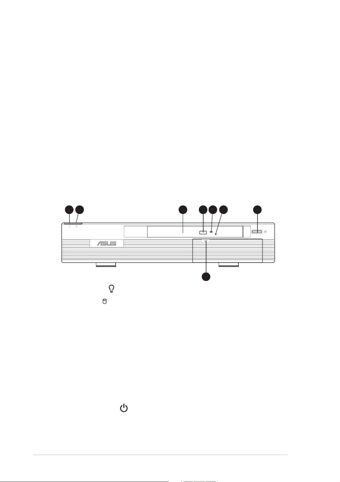
1.2 Front panel (external)
The front panel includes the power button, system LEDs, and the slim
optical disk drive.
11
22
1
2
11
22
33
3
33
44
55
4
44
66
5
6
55
66
77
7
77
88
8
88
1.1.
Power LED Power LED
1.
Power LED
1.1.
Power LED Power LED
2.2.
HDD LED HDD LED
2.
HDD LED
2.2.
HDD LED HDD LED
. .
. This LED lights up to indicate that the system is ON.
. .
. .
. This LED lights up when data is being read from or
. .
written to the hard disk drive.
3.3.
Optical driveOptical drive
3.
Optical drive. This is a slim optical disk drive.
3.3.
Optical driveOptical drive
4.4.
STOP/EJECT buttonSTOP/EJECT button
4.
STOP/EJECT button. Press this button to eject the disc loading tray.
4.4.
STOP/EJECT buttonSTOP/EJECT button
5.5.
Drive activity LEDDrive activity LED
5.
Drive activity LED. This LED lights up when you place a disc on the
5.5.
Drive activity LEDDrive activity LED
drive tray, and turns off when you remove the disc. The LED flashes
when data is being read from or written to the disc.
6.6.
Emergency eject pinholeEmergency eject pinhole
6.
Emergency eject pinhole. The emergency eject pinhole allows
6.6.
Emergency eject pinholeEmergency eject pinhole
you to manually eject a disc when the STOP button does not work due
to power failure or software problems. Insert the emergency eject pin
or a paper clip into this hole to manually eject the tray and the disc.
7.7.
Power button Power button
7.
Power button
7.7.
Power button Power button
8.8.
Front panel door lockFront panel door lock
8.
Front panel door lock. Press this lock to show the front panel I/O
8.8.
Front panel door lockFront panel door lock
. .
. Press this button to turn the system on.
. .
ports.
1-21-2
1-2
1-21-2
Chapter 1: System introductionChapter 1: System introduction
Chapter 1: System introduction
Chapter 1: System introductionChapter 1: System introduction
Page 13
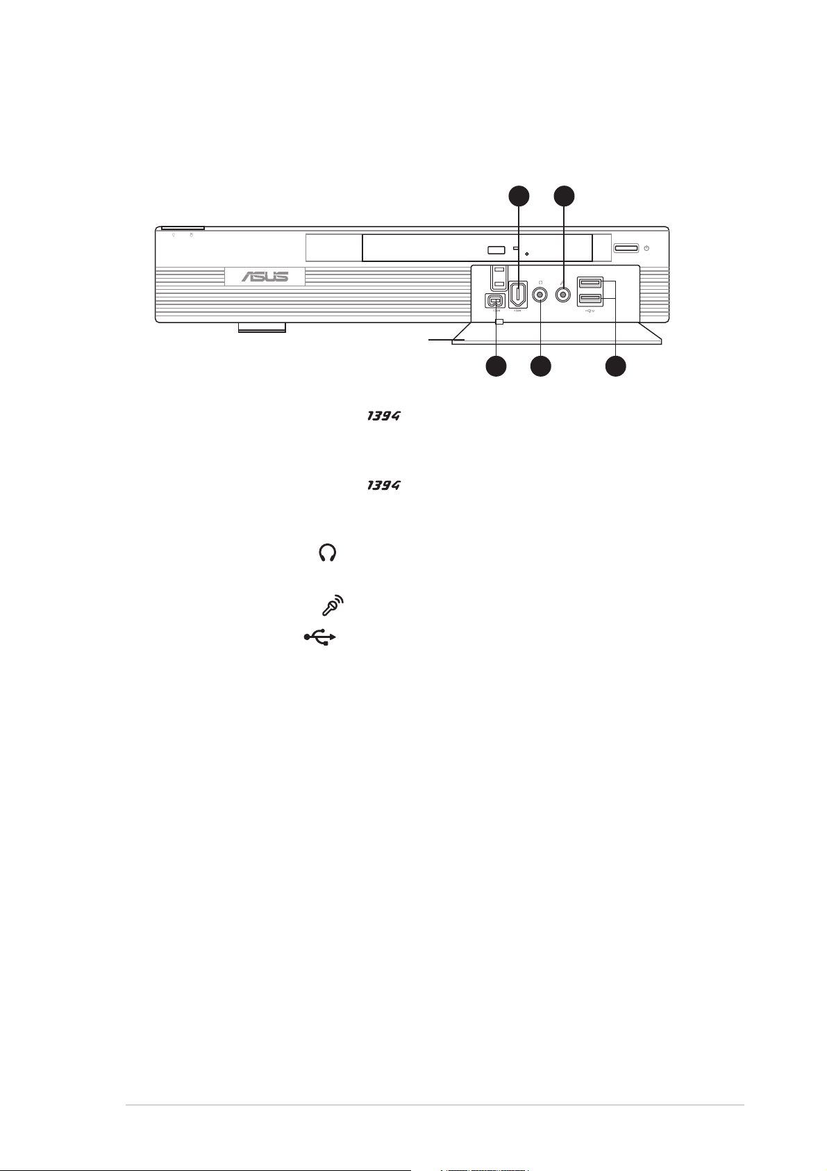
1.3 Front panel (internal)
The data and audio I/O ports are located inside the front panel door. Press
the front panel door lock to open.
Front panel doorFront panel door
Front panel door
Front panel doorFront panel door
9.9.
4-pin IEEE 1394 port 4-pin IEEE 1394 port
9.
4-pin IEEE 1394 port
9.9.
4-pin IEEE 1394 port 4-pin IEEE 1394 port
1010
10
1010
99
9
99
. .
. This port provides high-speed
. .
11
22
1
2
11
22
11
11
1
1
11
11
11
33
1
3
11
33
connectivity for IEEE 1394-compliant audio/video devices, storage
peripherals, and other PC devices.
10.10.
6-pin IEEE 1394 port 6-pin IEEE 1394 port
10.
6-pin IEEE 1394 port
10.10.
6-pin IEEE 1394 port 6-pin IEEE 1394 port
. This port provides high-speed
connectivity for IEEE 1394-compliant audio/video devices, storage
peripherals, and other PC devices.
11.11.
Headphone port Headphone port
11.
Headphone port
11.11.
Headphone port Headphone port
. .
. This port connects a headphone with a stereo
. .
mini-plug.
12.12.
Microphone port Microphone port
12.
Microphone port
12.12.
Microphone port Microphone port
13.13.
USB 2.0 ports USB 2.0 ports
13.
USB 2.0 ports
13.13.
USB 2.0 ports USB 2.0 ports
. .
. This Mic (pink) port connects a microphone.
. .
. .
. These Universal Serial Bus 2.0 (USB 2.0)
. .
ports are available for connecting USB 2.0 devices such as a mouse,
printer, scanner, camera, PDA, and others.
ASUS Pundit P2-AE2ASUS Pundit P2-AE2
ASUS Pundit P2-AE2
ASUS Pundit P2-AE2ASUS Pundit P2-AE2
1-31-3
1-3
1-31-3
Page 14
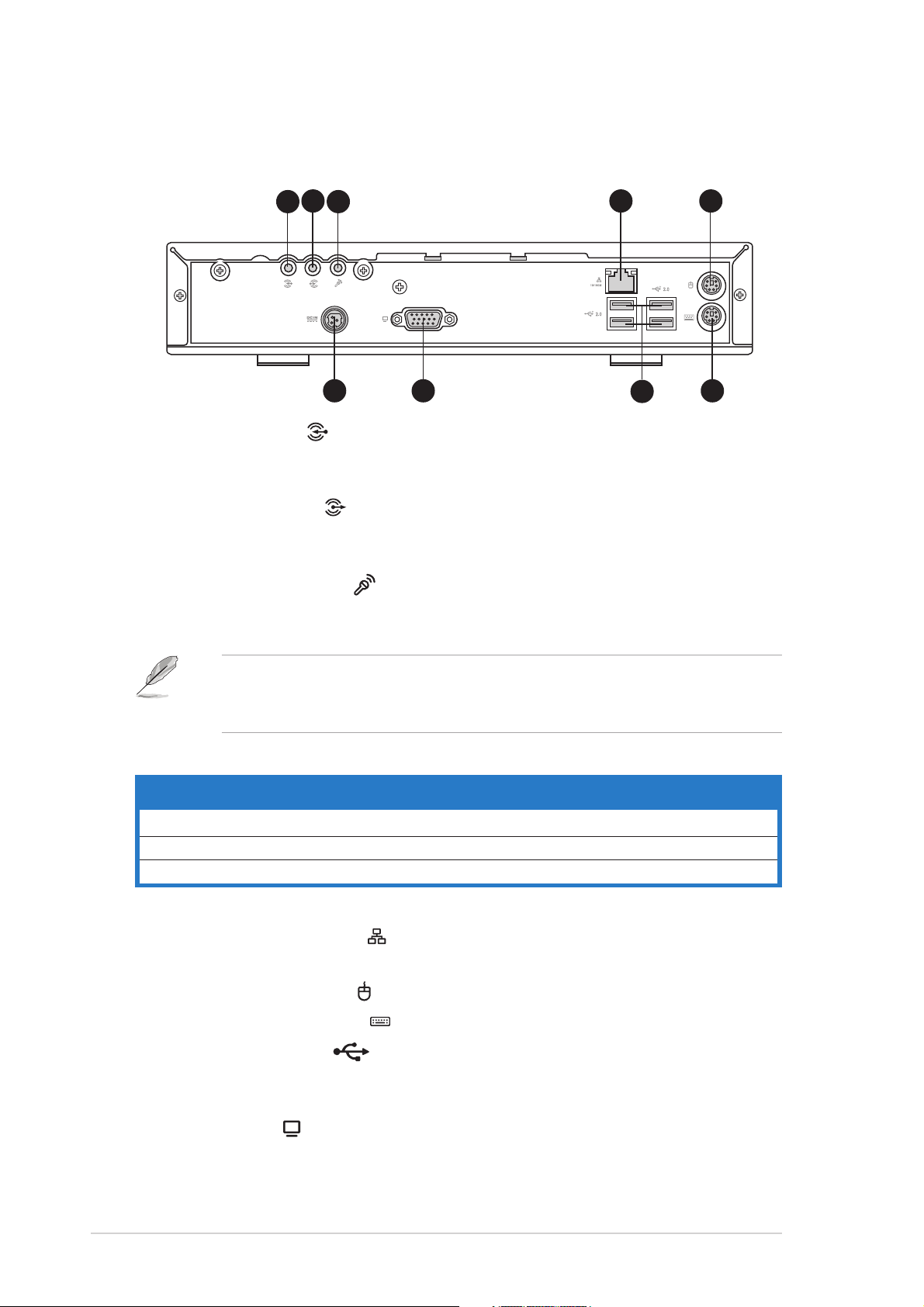
1.4 Rear panel
The system rear panel includes the power connector and several I/O ports
that allow convenient connection of devices.
1.1.
Line In port Line In port
1.
Line In port
1.1.
Line In port Line In port
44
4
11
1
11
33
22
3
2
33
22
99
9
99
. .
. This Line In (light blue) port connects a tape
. .
88
8
88
44
77
7
77
55
5
55
66
6
66
player or other audio sources. In 6-channel mode, the function of this
port becomes Low Frequency Enhanced Output/Center.
2.2.
Line Out port Line Out port
2.
Line Out port
2.2.
Line Out port Line Out port
. .
. This Line Out (lime) port connects a headphone
. .
or a speaker. In 4/6-channel mode, the function of this port becomes
Front Speaker Out.
3.3.
Microphone port Microphone port
3.
Microphone port
3.3.
Microphone port Microphone port
. .
. This Microphone (pink) port connects a
. .
microphone. In 4/6-channel mode, the function of this port becomes
Surround Speaker.
The functions of the Line Out, Line In, and Microphone ports change
when you select the 6-channel configuration. Refer to the table below
for audio ports function variation.
Audio ports function variationAudio ports function variation
Audio ports function variation
Audio ports function variationAudio ports function variation
PortPort
Port
PortPort
Light Blue Line In No function LFE Output*/Center
Lime Line Out Front Speaker Out Front Speaker Out
Pink Mic In Surround Surround
* Low Frequency Enhanced Output
4.4.
LAN (RJ-45) port LAN (RJ-45) port
4.
LAN (RJ-45) port
4.4.
LAN (RJ-45) port LAN (RJ-45) port
Headphone/2-ChannelHeadphone/2-Channel
Headphone/2-Channel
Headphone/2-ChannelHeadphone/2-Channel
. .
. This port allows Fast Ethernet connection to
. .
4-Channel4-Channel
4-Channel
4-Channel4-Channel
6-Channel6-Channel
6-Channel
6-Channel6-Channel
a Local Area Network (LAN) through a network hub.
55
..
PS/2 mouse port PS/2 mouse port
5
.
PS/2 mouse port
55
..
PS/2 mouse port PS/2 mouse port
6.6.
PS/2 keyboard port PS/2 keyboard port
6.
PS/2 keyboard port
6.6.
PS/2 keyboard port PS/2 keyboard port
7.7.
USB 2.0 ports USB 2.0 ports
7.
USB 2.0 ports
7.7.
USB 2.0 ports USB 2.0 ports
. This green 6-pin connector is for a PS/2 mouse.
. This purple 6-pin connector is for a PS/2 keyboard.
. .
. These Universal Serial Bus 2.0 ports are
. .
available for connecting USB 2.0 devices such as a mouse, printer,
scanner, camera, PDA, and others.
1-41-4
1-4
1-41-4
8.8.
VGA port VGA port
8.
VGA port
8.8.
VGA port VGA port
9.9.
Power connector.Power connector.
9.
Power connector. Connects the power plug is for the power cable
9.9.
Power connector.Power connector.
. .
. Connects a VGA monitor.
. .
and plug.
Chapter 1: System introductionChapter 1: System introduction
Chapter 1: System introduction
Chapter 1: System introductionChapter 1: System introduction
Page 15
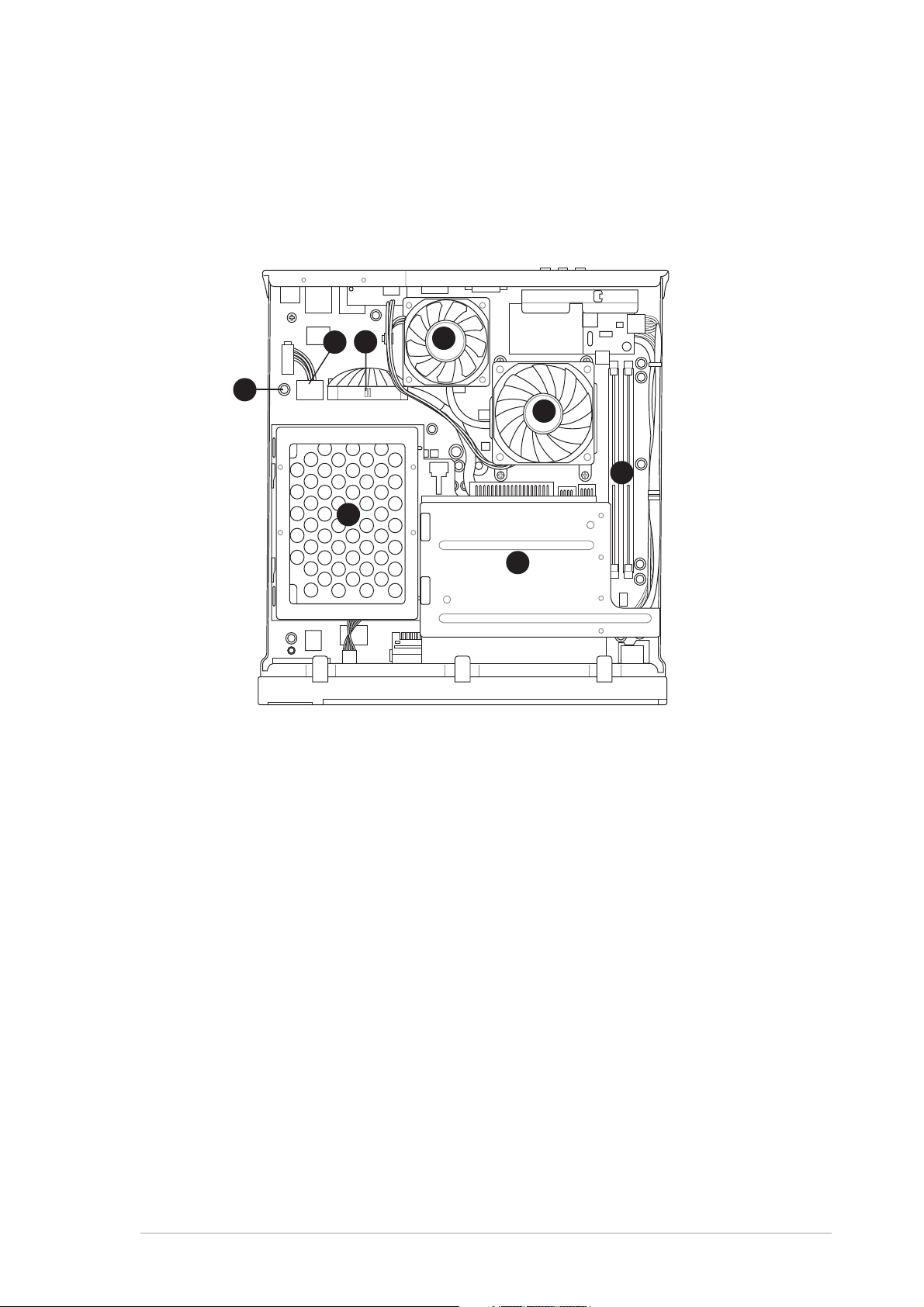
1.5 Internal components
The illustration below is the internal view of the system when you remove
the top cover. The installed components are labeled for your reference.
Proceed to Chapter 2 for instructions on installing other system
components.
44
4
33
3
22
33
2
22
11
1
11
77
7
77
44
55
5
55
66
6
66
88
8
88
1.1.
Standby power LEDStandby power LED
1.
Standby power LED
1.1.
Standby power LEDStandby power LED
2.2.
HDD power plug (to HDD power connector)HDD power plug (to HDD power connector)
2.
HDD power plug (to HDD power connector)
2.2.
HDD power plug (to HDD power connector)HDD power plug (to HDD power connector)
3.3.
IDE cable (to HDD connector)IDE cable (to HDD connector)
3.
IDE cable (to HDD connector)
3.3.
IDE cable (to HDD connector)IDE cable (to HDD connector)
4.4.
Chassis fanChassis fan
4.
Chassis fan
4.4.
Chassis fanChassis fan
5.5.
CPU fanCPU fan
5.
CPU fan
5.5.
CPU fanCPU fan
6.6.
DIMM socketsDIMM sockets
6.
DIMM sockets
6.6.
DIMM socketsDIMM sockets
7.7.
HDD metal trayHDD metal tray
7.
HDD metal tray
7.7.
HDD metal trayHDD metal tray
8.8.
Optical drive shieldOptical drive shield
8.
Optical drive shield
8.8.
Optical drive shieldOptical drive shield
ASUS Pundit P2-AE2ASUS Pundit P2-AE2
ASUS Pundit P2-AE2
ASUS Pundit P2-AE2ASUS Pundit P2-AE2
1-51-5
1-5
1-51-5
Page 16

1-61-6
1-6
1-61-6
Chapter 1: System introductionChapter 1: System introduction
Chapter 1: System introduction
Chapter 1: System introductionChapter 1: System introduction
Page 17

Chapter 2
This chapter provides step-by-step
instructions on how to install
components in the system.
ASUS Pundit P2-AE2ASUS Pundit P2-AE2
ASUS Pundit P2-AE2
ASUS Pundit P2-AE2ASUS Pundit P2-AE2
Basic installation
Page 18
2.1 Preparation
Before you proceed, make sure that you have all the components that you
plan to install in the system.
Basic components to installBasic components to install
Basic components to install
Basic components to installBasic components to install
1. Hard disk drive (HDD)
2. Central processing unit (CPU)
3. DDR Dual Inline Memory Module (DIMM)
ToolTool
Tool
ToolTool
Phillips (cross) screw driver
2.2 Before you proceed
Take note of the following precautions before you install the system components.
• Unplug the AC adapter cable from the wall socket before touching
any component.
• Use a grounded wrist strap or touch a safely grounded object or to
a metal object, such as the power supply case, before handling
components to avoid damaging them due to static electricity.
• Hold components by the edges to avoid touching the ICs on them.
• Whenever you uninstall any component, place it on a grounded
antistatic pad or in the bag that came with the component.
Before you install or remove any component, ensureBefore you install or remove any component, ensure
•
Before you install or remove any component, ensure
Before you install or remove any component, ensureBefore you install or remove any component, ensure
that the AC power adapter is detached from the powerthat the AC power adapter is detached from the power
that the AC power adapter is detached from the power
that the AC power adapter is detached from the powerthat the AC power adapter is detached from the power
outlet. outlet.
outlet. Failure to do so may cause severe damage to the
outlet. outlet.
motherboard, peripherals, and/or components.
Onboard LEDOnboard LED
Onboard LED
Onboard LEDOnboard LED
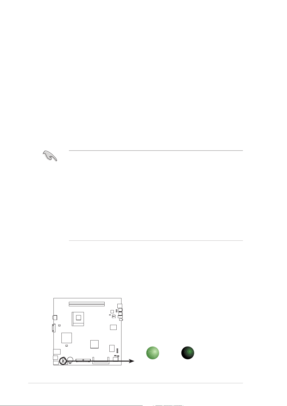
The system motherboard comes with a standby power LED. The green LED
lights up to indicate that the system is ON, in sleep mode, or in soft-off
mode. This is a reminder that you should shut down the system and unplug
the AC adapter cable before removing or plugging in any system
component. The illustration below shows the location of the onboard LED.
2-22-2
2-2
2-22-2
Onboard LED
ON
Standby
Power
SB_PWR1
OFF
Powered
Off
Chapter 2: Basic installationChapter 2: Basic installation
Chapter 2: Basic installation
Chapter 2: Basic installationChapter 2: Basic installation
Page 19
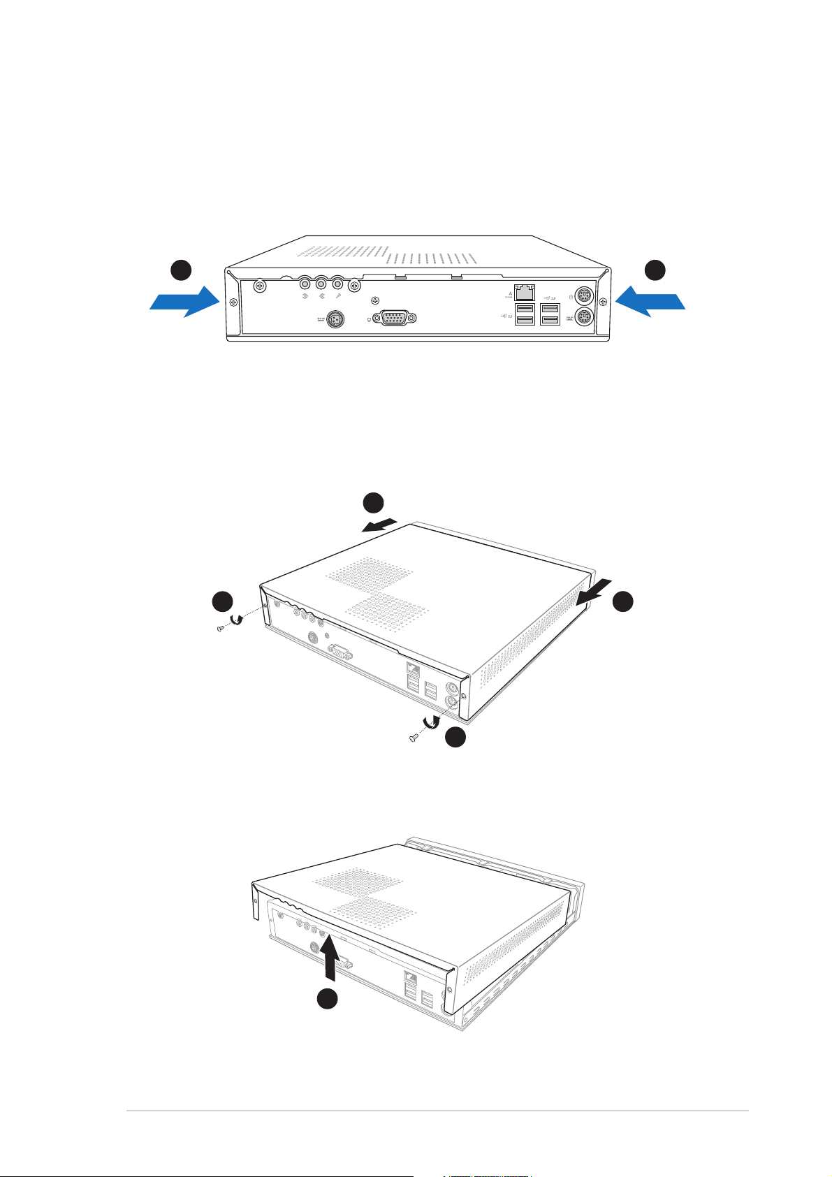
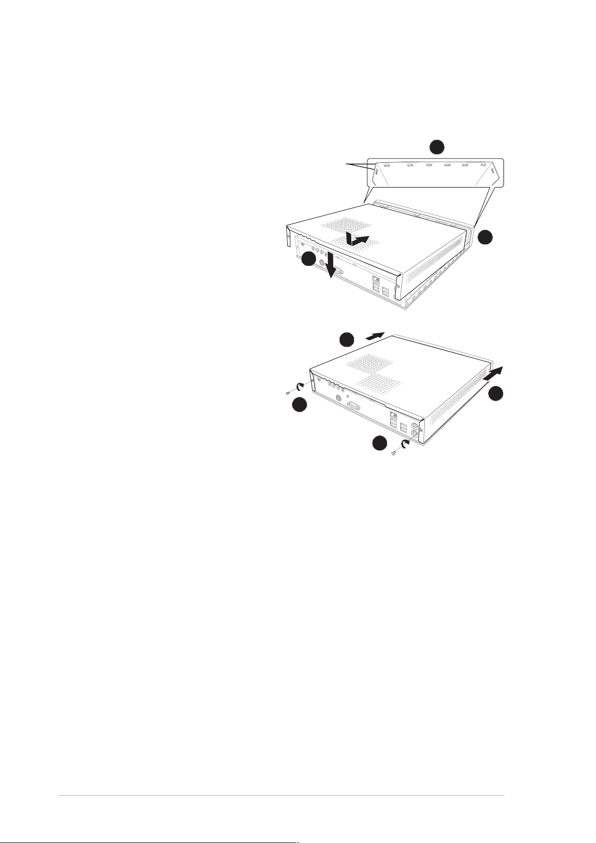
2.3 Removing the top cover
To remove the top cover:
1. On the rear panel, locate the two screws that secure the top cover to
the chassis.
11
1
11
11
1
11
2. Use a Phillips (cross) screw driver to remove the top cover screws.
Keep the screws for later use.
3. Pull the top cover slightly toward the rear panel until the side tabs are
disengaged from the chassis.
33
3
33
22
2
22
33
3
33
22
2
22
4. Hold the center edge of the top cover, then lift. Set the top cover
aside.
44
4
44
ASUS Pundit P2-AE2ASUS Pundit P2-AE2
ASUS Pundit P2-AE2
ASUS Pundit P2-AE2ASUS Pundit P2-AE2
2-32-3
2-3
2-32-3
Page 20
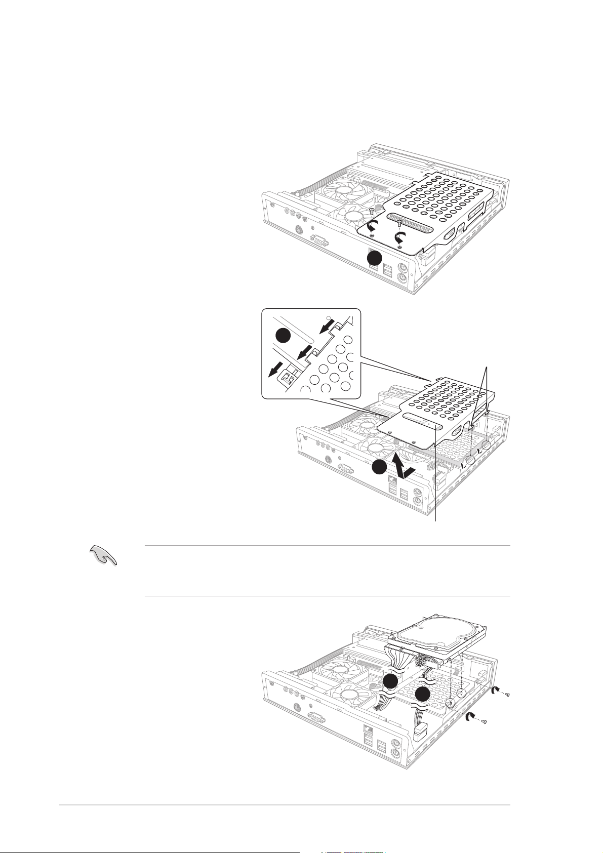
2.4 Installing a hard disk drive (HDD)
The system supports one UltraATA133 IDE hard disk drive (HDD).
To install a hard disk drive:
1. Remove the two metal
cover screws. Keep the
screws for later use.
11
1
11
2. Use the metal cover
handle to slide the cover
toward the rear panel
until the side hooks
disengage from the HDD
metal tray and optical
drive shield tabs.
AA
A
AA
Side hooksSide hooks
Side hooks
Side hooksSide hooks
Side hooksSide hooks
Side hooks
Side hooksSide hooks
Lift the metal cover,
then set aside.
Set your hard disk drive as Master device before connecting the IDE
cable and power plug. Refer to the HDD documentation on how to set
the drive as Master device.
3. Connect the 40-pin IDE
cable to the IDE
connector on the drive.
4. Connect the 4-pin power
plug to the HDD power
connector.
BB
B
BB
HandleHandle
Handle
HandleHandle
33
3
33
44
4
44
2-42-4
2-4
2-42-4
Chapter 2: Basic installationChapter 2: Basic installation
Chapter 2: Basic installation
Chapter 2: Basic installationChapter 2: Basic installation
Page 21
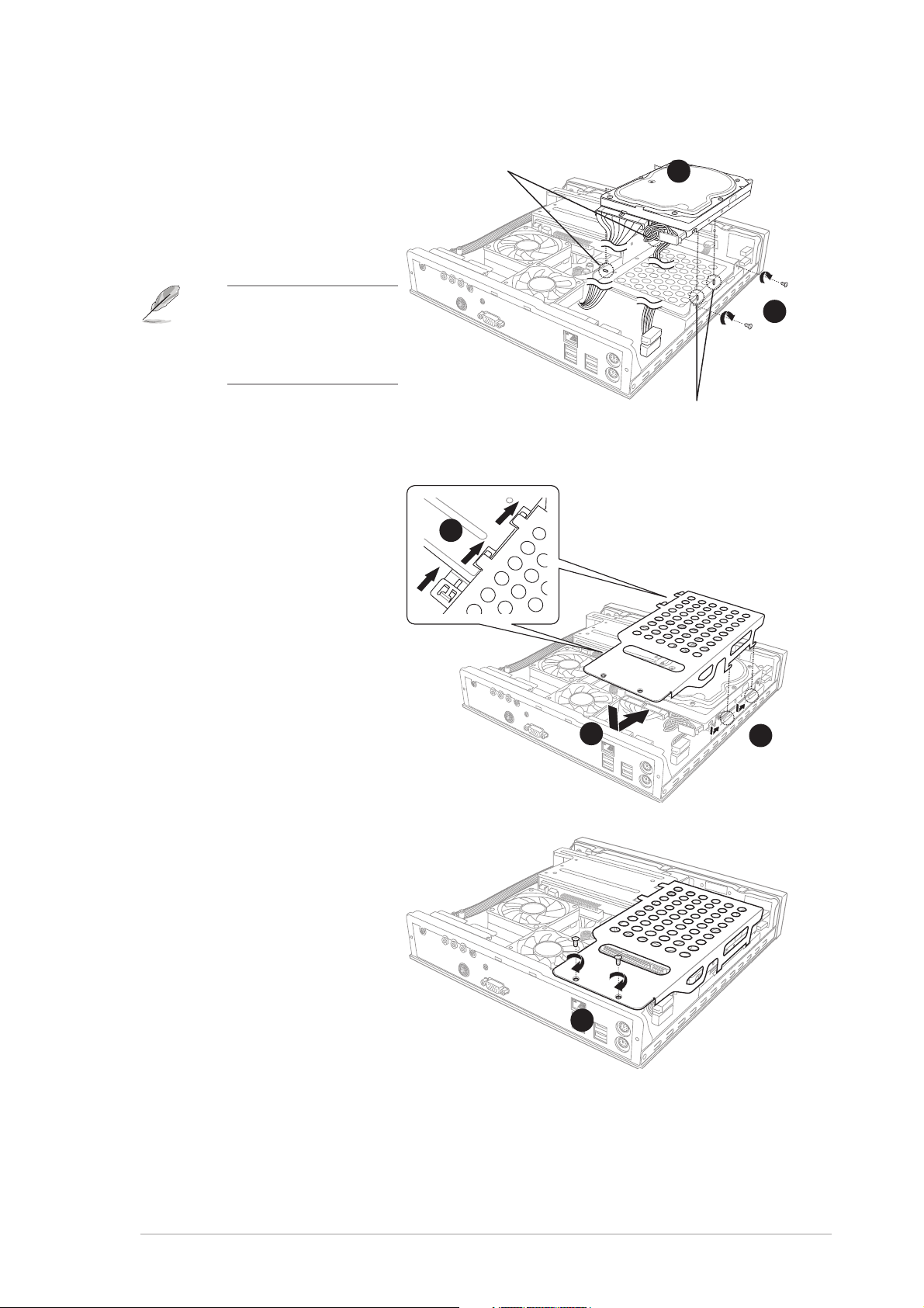
5. Place the drive on the
tray. Insert the tray
metal tacks into the
drive screw holes (two
at the side and two at
the bottom).
Metal tacksMetal tacks
Metal tacks
Metal tacksMetal tacks
(To side of the drive)
55
5
55
Insert the side metal
tacks before
inserting the bottom
metal tacks.
6. Secure the drive with
two side screws.
7. Align the metal cover
side hooks with the HDD
metal tray and optical
drive shield tabs (A),
then slide the metal
cover toward the front
panel until it fits in place
(B).
AA
A
AA
Metal tacksMetal tacks
Metal tacks
Metal tacksMetal tacks
(To bottom of the drive)
BB
B
BB
AA
A
AA
66
6
66
8. Secure the metal cover
with screws that you
removed earlier.
ASUS Pundit P2-AE2ASUS Pundit P2-AE2
ASUS Pundit P2-AE2
ASUS Pundit P2-AE2ASUS Pundit P2-AE2
88
8
88
2-52-5
2-5
2-52-5
Page 22
2.5 Installing a CPU
The system motherboard has a surface mount 754-pin Zero Insertion Force
(ZIF) socket. This socket is specifically designed for the AMD Athlon™ 64/
Athlon™ XP/Sempron™ processor in the 754-pin package.
2.5.12.5.1
2.5.1
2.5.12.5.1
Removing the CPU fan and heatsink assemblyRemoving the CPU fan and heatsink assembly
Removing the CPU fan and heatsink assembly
Removing the CPU fan and heatsink assemblyRemoving the CPU fan and heatsink assembly
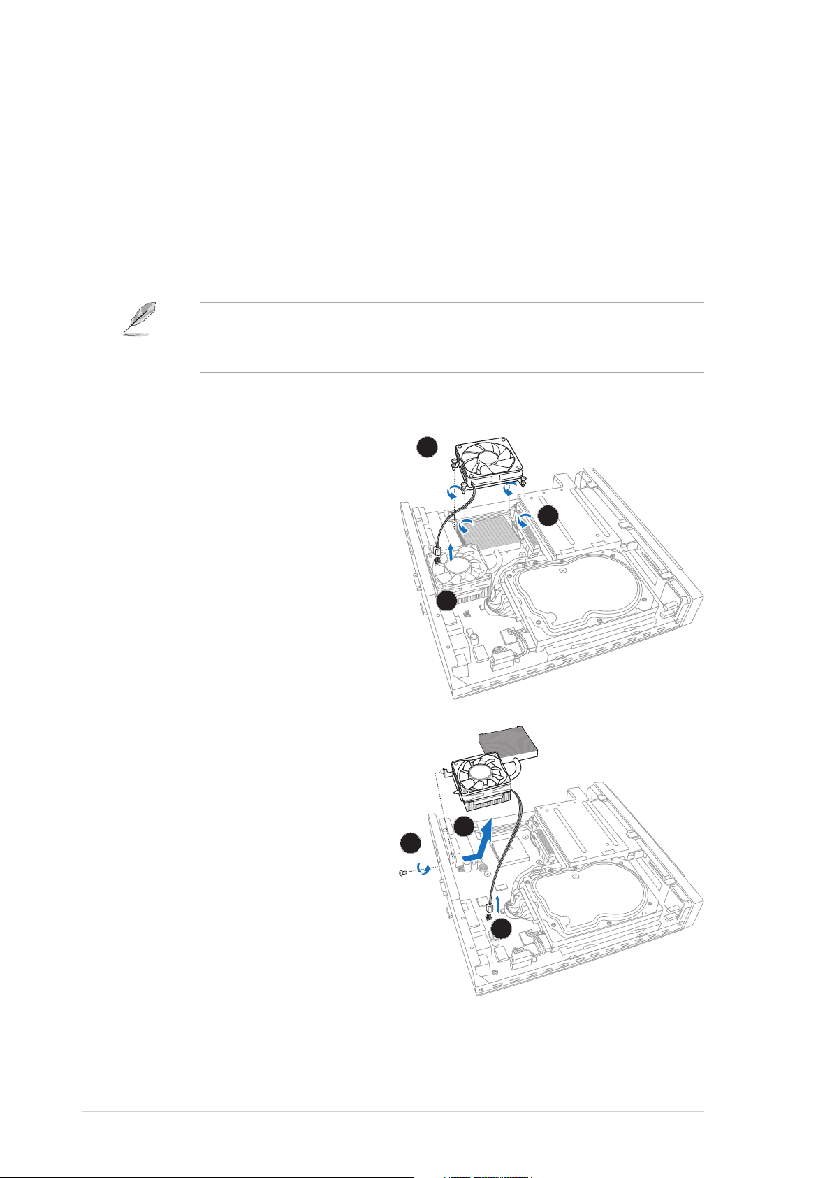
You must remove the CPU fan and heatsink assembly before you can install
a CPU.
The system comes with a pre-installed proprietary CPU fan and heatsink
assembly for optimum CPU thermal control and system ventilation. Do
not replace the CPU fan with other models.
To remove the CPU fan and heatsink assembly:
1. Loosen the CPU fan screws.
33
3
33
2. Disconnect the CPU fan cable
from the CPU fan connector
on the motherboard.
11
1
11
3. Lift the CPU fan.
22
2
22
4. Disconnect the chassis fan
cable from the chassis fan
connector.
5. Remove the chassis fan and
heatsink assembly screw
from the rear panel.
6. Move the chassis fan and
heatsink assembly toward
the direction of the front
panel, then lift.
Set the chassis fan and
heatsink assembly aside.
2-62-6
2-6
2-62-6
66
6
66
55
5
55
44
4
44
Chapter 2: Basic installationChapter 2: Basic installation
Chapter 2: Basic installation
Chapter 2: Basic installationChapter 2: Basic installation
Page 23
2.5.22.5.2
2.5.2
2.5.22.5.2
CPU installationCPU installation
CPU installation
CPU installationCPU installation
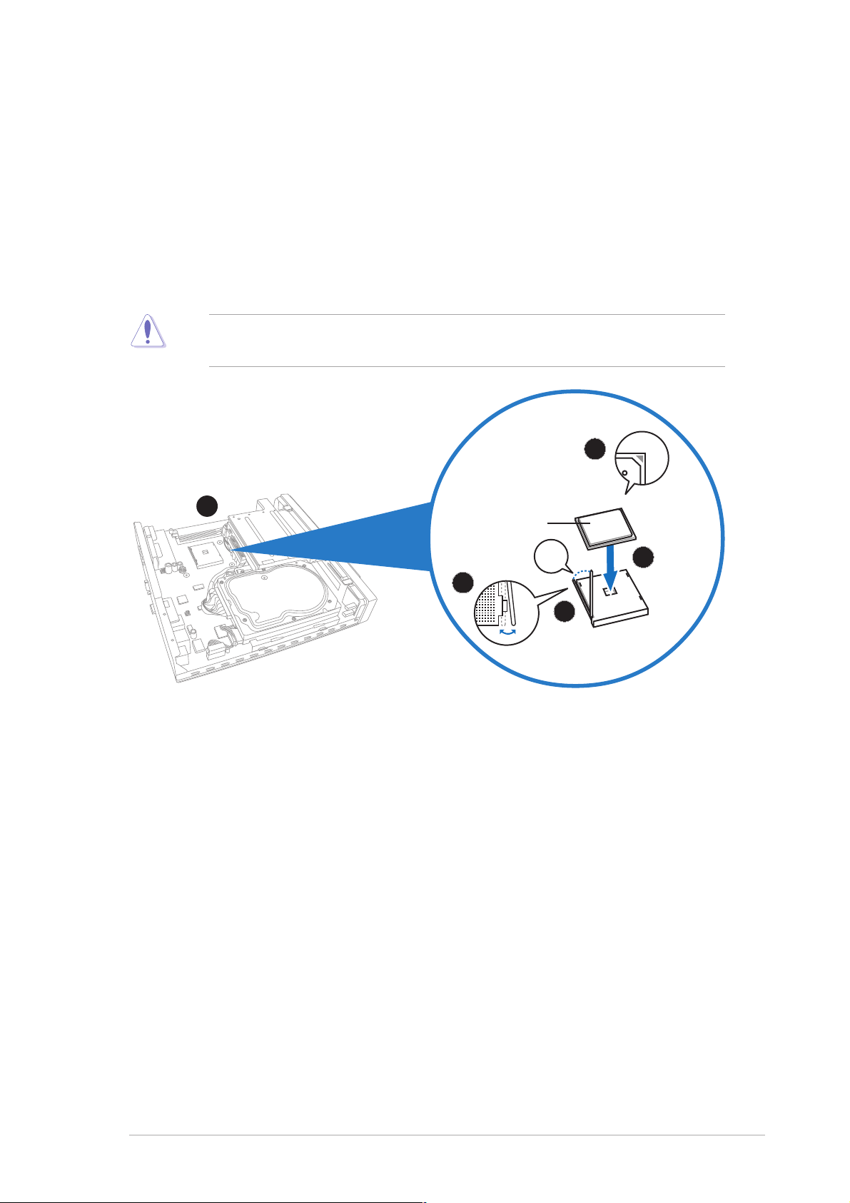
1. Locate the 754-pin CPU socket on the motherboard.
2. Unlock the socket by pressing the lever sideways then lifting it up to a
90° angle.
3. Position the CPU above the socket such that its marked corner (gold
mark) matches the base of the socket lever.
4. Carefully insert the CPU to the socket until it fits in place.
The CPU fits only in one correct orientation. Do not force the CPU into
the socket to prevent bending the pins and damaging the CPU!
33
3
33
11
1
11
CPUCPU
CPU
CPUCPU
˚
55
5
55
22
2
22
44
4
44
5. When the CPU is in place, push down the socket lever to secure the
CPU. The lever clicks on the side tab to indicate that it is locked.
ASUS Pundit P2-AE2ASUS Pundit P2-AE2
ASUS Pundit P2-AE2
ASUS Pundit P2-AE2ASUS Pundit P2-AE2
2-72-7
2-7
2-72-7
Page 24
2.5.32.5.3
2.5.3
2.5.32.5.3
Reinstalling the CPU fan and heatsinkReinstalling the CPU fan and heatsink
Reinstalling the CPU fan and heatsink
Reinstalling the CPU fan and heatsinkReinstalling the CPU fan and heatsink
assemblyassembly
assembly
assemblyassembly
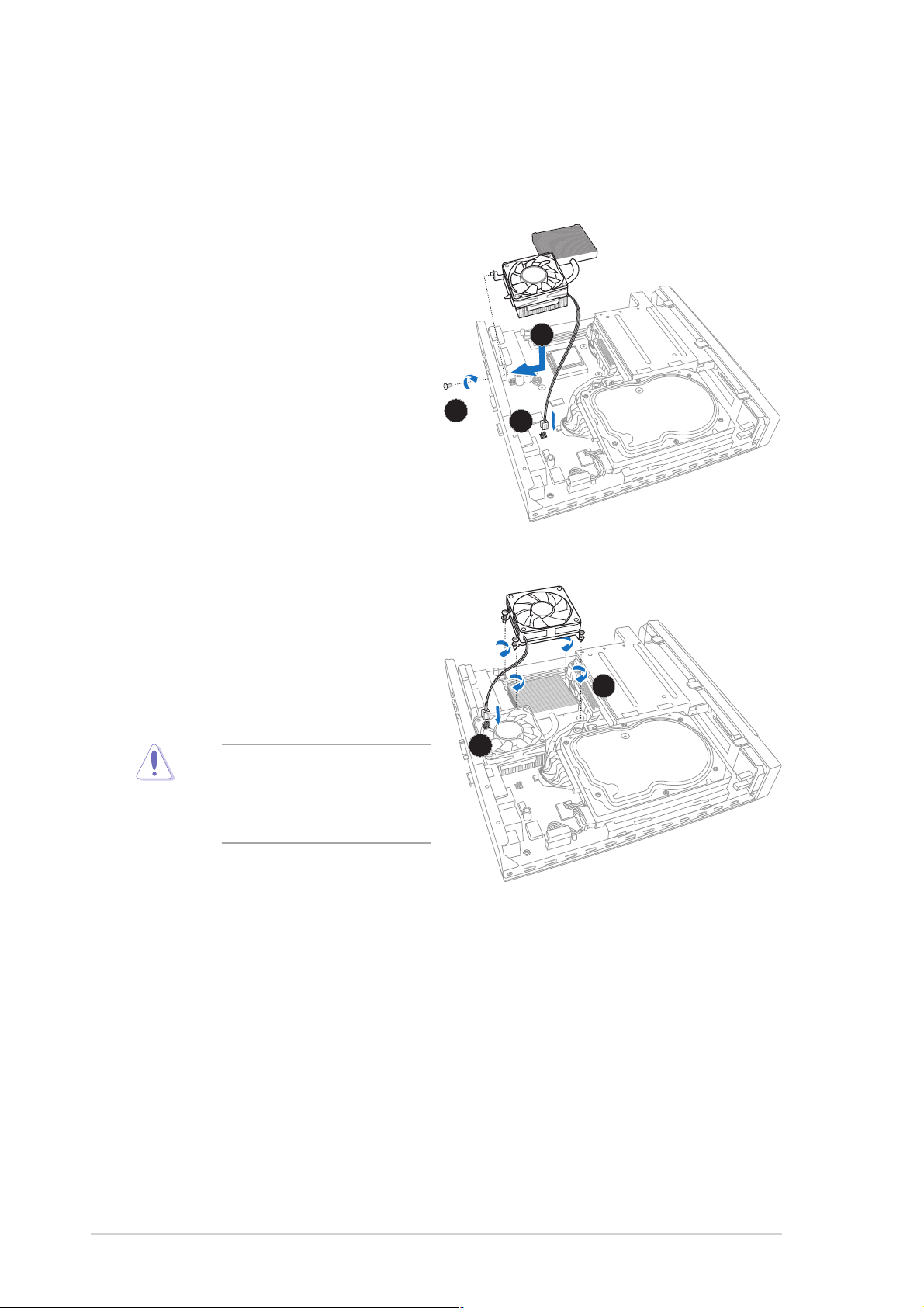
To reinstall the CPU fan and heatsink assembly:
1. Place the chassis fan and
heatsink assembly on top of
the installed CPU. Make sure
that the CPU heatsink sits
properly on top of the CPU.
11
1
11
2. Secure the chassis fan and
heatsink assembly with a
screw from the rear panel.
22
2
22
33
3
33
3. Connect the chassis fan
cable to the chassis fan
connector. See Chapter 4 for
the location of the chassis
fan connector.
4. Place the CPU fan over the
CPU heatsink, then fasten
the CPU fan screws to the
motherboard in a diagonal
pattern starting from two
opposite corners.
Do not overtighten the
CPU fan screws! Doing so
may damage the
motherboard.
5. Connect the CPU fan cable to
the CPU fan connector. See
Chapter 4 for the location of
the CPU fan connector.
44
4
44
55
5
55
2-82-8
2-8
2-82-8
Chapter 2: Basic installationChapter 2: Basic installation
Chapter 2: Basic installation
Chapter 2: Basic installationChapter 2: Basic installation
Page 25
2.6 Installing a DIMM
The system motherboard comes with two Double Data Rate (DDR) Dual
Inline Memory Module (DIMM) sockets. These sockets support up to 2 GB
system memory using unbuffered non-ECC PC2700/2100/1600 DIMMs.
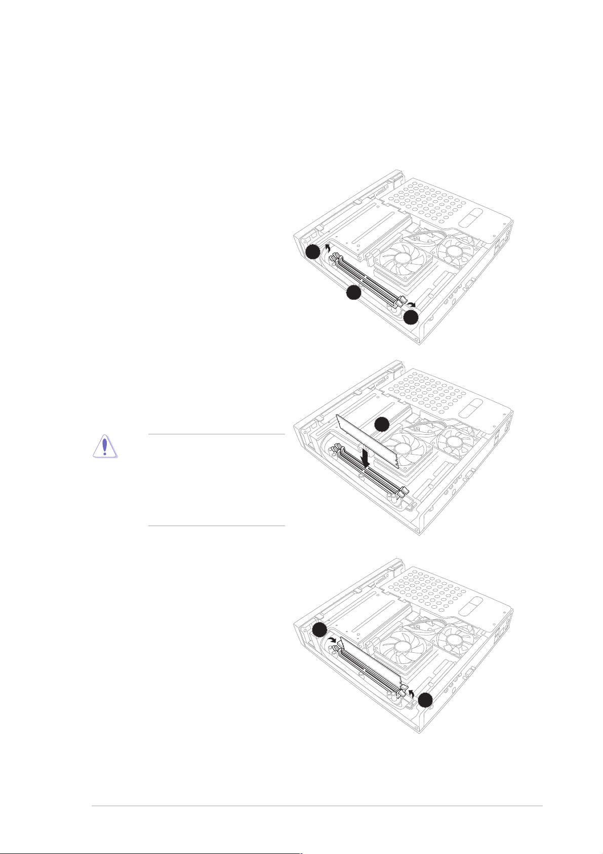
To install a DDR DIMM:
1. Locate the two DIMM sockets
on the motherboard.
2. Unlock a socket by pressing
the retaining clips outward.
22
2
22
11
1
11
22
2
22
3. Align a DIMM on the socket
such that the notch on the
DIMM matches the break on
the socket.
33
3
33
a notch so that it fits in
only one direction. DO
NOT force a DIMM into a
socket to avoid damaging
the DIMM.
4. Firmly insert the DIMM into
the socket until the retaining
clips snap back in place and
the DIMM is properly seated.
3A DDR DIMM is keyed with
44
4
44
44
4
44
ASUS Pundit P2-AE2ASUS Pundit P2-AE2
ASUS Pundit P2-AE2
ASUS Pundit P2-AE2ASUS Pundit P2-AE2
2-92-9
2-9
2-92-9
Page 26
2.7 Replacing the top cover
Replace the top cover after installing the components.
To replace the top cover:
1. Position the front edge of
the top cover at least two
inches from the front panel
cover.
2. Fit the top cover hooks with
the chassis side tabs and the
front panel cover tabs.
3. Lower the rear edge of the
top cover as shown.
4. Push the top cover slightly
toward the front panel until
it fits in place.
5. Secure the top cover with
two screws that you
removed earlier.
33
3
33
55
5
55
HooksHooks
Hooks
HooksHooks
22
2
22
11
1
11
44
4
44
44
4
44
55
5
55
2-102-10
2-10
2-102-10
Chapter 2: Basic installationChapter 2: Basic installation
Chapter 2: Basic installation
Chapter 2: Basic installationChapter 2: Basic installation
Page 27
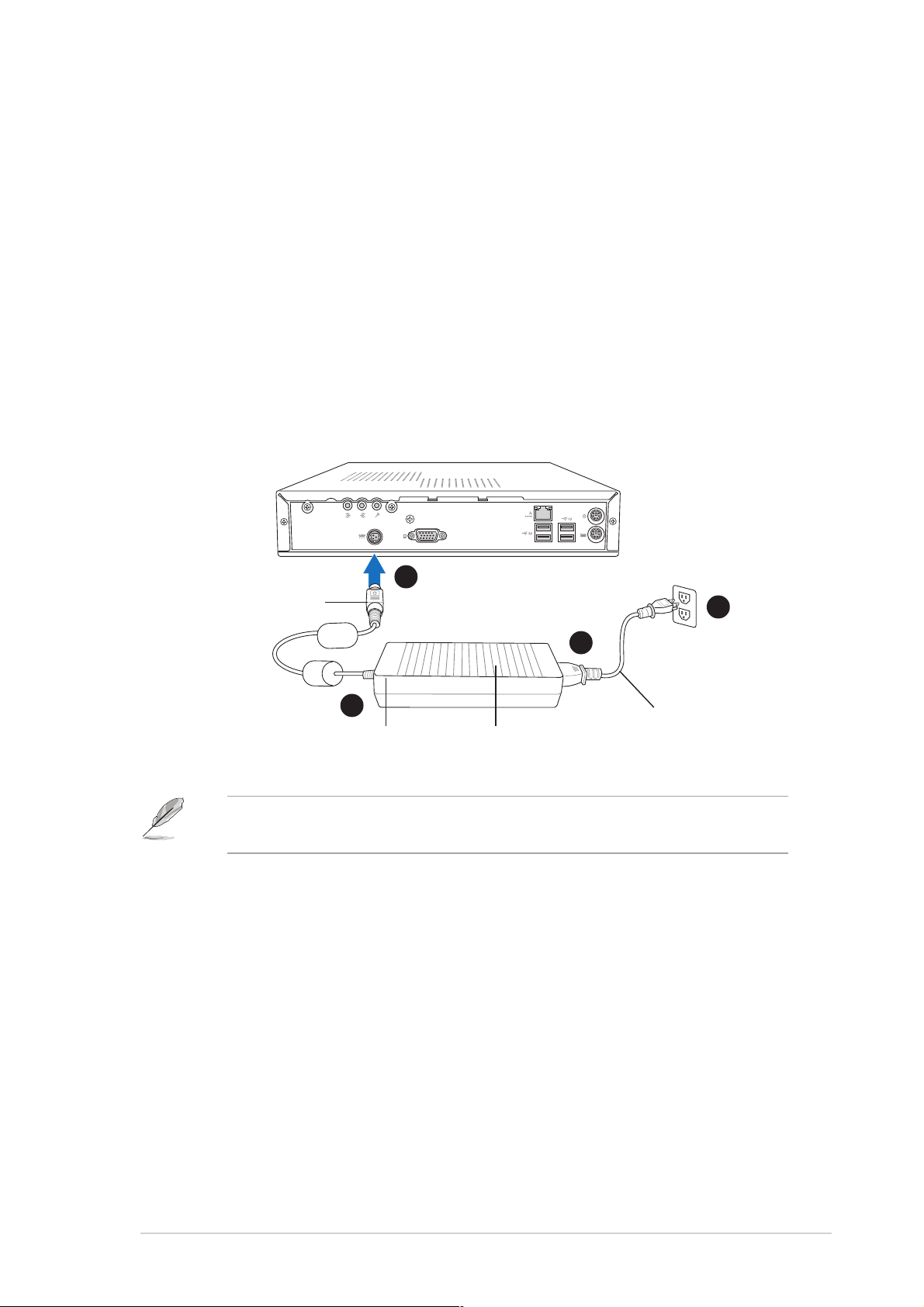
2.8 Connecting the power cable
The system package includes a universal AC power adapter (100V - 240V)
with power cable and plug. The AC power adapter allows you to use your
system in any location regardless of the voltage output.
To connect the AC power adapter to the system:
1. Connect the power cable (female plug) to the AC power adapter.
2. Connect the other end of the power cable (male plug) to a power
outlet.
3. Check the AC power adapter LED. The LED lights up to indicate that
the power from the source is within the operating range.
4. Connect the DC IN power plug to the system DC IN socket.
DC IN power plugDC IN power plug
DC IN power plug
DC IN power plugDC IN power plug
Use an outlet adapter if the power plug does not fit the power outlet in
your area.
44
4
44
33
3
33
Power LEDPower LED
Power LED
Power LEDPower LED
11
1
11
Power adapterPower adapter
Power adapter
Power adapterPower adapter
22
2
22
Power cablePower cable
Power cable
Power cablePower cable
ASUS Pundit P2-AE2ASUS Pundit P2-AE2
ASUS Pundit P2-AE2
ASUS Pundit P2-AE2ASUS Pundit P2-AE2
2-112-11
2-11
2-112-11
Page 28

2.9 Connecting external devices
2.9.12.9.1
2.9.1
2.9.12.9.1
To the front panelTo the front panel
To the front panel
To the front panelTo the front panel
CameraCamera
Camera
CameraCamera
HDDHDD
HDD
HDDHDD
HeadphoneHeadphone
Headphone
HeadphoneHeadphone
MicMic
Mic
MicMic
ScannerScanner
Scanner
ScannerScanner
2.9.22.9.2
2.9.2
2.9.22.9.2
Line InLine In
Line In
Line InLine In
To the rear panelTo the rear panel
To the rear panel
To the rear panelTo the rear panel
Line OutLine Out
Line Out
Line OutLine Out
MicMic
Mic
MicMic
VGA MonitorVGA Monitor
VGA Monitor
VGA MonitorVGA Monitor
Hub or RouterHub or Router
Hub or Router
Hub or RouterHub or Router
USB MouseUSB Mouse
USB Mouse
USB MouseUSB Mouse
PS/2 MousePS/2 Mouse
PS/2 Mouse
PS/2 MousePS/2 Mouse
PS/2 KBPS/2 KB
PS/2 KB
PS/2 KBPS/2 KB
2-122-12
2-12
2-122-12
Chapter 2: Basic installationChapter 2: Basic installation
Chapter 2: Basic installation
Chapter 2: Basic installationChapter 2: Basic installation
Page 29

Chapter 3
This chapter helps you power up
the system and install drivers and
utilities from the support CD.
ASUS Pundit P2-AE2ASUS Pundit P2-AE2
ASUS Pundit P2-AE2
ASUS Pundit P2-AE2ASUS Pundit P2-AE2
Getting started
Page 30

3.1 Installing an operating system
This system supports Windows® 2000/XP operating systems (OS). Always
install the latest OS version and corresponding updates to maximize the
features of your system.
• Motherboard settings and hardware options vary. Use the setup
procedures presented in this chapter for reference only. Refer to
your OS documentation for detailed information.
®
• Make sure that you install Windows
Windows® XP Service Pack 1 or later versions before installing the
drivers for better compatibility and system stability.
2000 Service Pack 4 or the
3.2 Support CD information
The support CD that came with the system package contains the drivers,
software applications, and utilities that you can install to avail all system
features.
The contents of the support CD are subject to change at any time
without notice. Visit the ASUS website (www.asus.com) for updates.
3.2.13.2.1
3.2.1
3.2.13.2.1
Running the support CDRunning the support CD
Running the support CD
Running the support CDRunning the support CD
Place the support CD to the optical drive. The CD automatically displays the
Drivers Drivers
Dr iv er s menu if Autorun is enabled in your computer.
Drivers Drivers
Click an icon toClick an icon to
Click an icon to
Click an icon toClick an icon to
display supportdisplay support
display support
display supportdisplay support
CD/motherboardCD/motherboard
CD/motherboard
CD/motherboardCD/motherboard
informationinformation
information
informationinformation
Click an item to installClick an item to install
Click an item to install
Click an item to installClick an item to install
3-23-2
3-2
3-23-2
Autorun Autorun
If
Autorun is NOT enabled in your computer, browse the contents of
Autorun Autorun
the support CD to locate the file ASSETUP.EXE from the BIN folder.
Double-click the
ASSETUP.EXEASSETUP.EXE
ASSETUP.EXE to run the CD.
ASSETUP.EXEASSETUP.EXE
Chapter 3: Getting startedChapter 3: Getting started
Chapter 3: Getting started
Chapter 3: Getting startedChapter 3: Getting started
Page 31

3.2.23.2.2
3.2.2
3.2.23.2.2
The drivers menu shows the available device drivers if the system detects
installed devices. Install the necessary drivers to activate the devices.
VIA 4 in 1 driversVIA 4 in 1 drivers
VIA 4 in 1 drivers
VIA 4 in 1 driversVIA 4 in 1 drivers
Drivers menuDrivers menu
Drivers menu
Drivers menuDrivers menu
This item installs the following drivers:
- VIA Registry (INF) driver
- VIA AGP VxD driver
- VIA ATAPI vendor support driver
- VIA PCI IRQ Miniport driver.
K8M800 Display DriverK8M800 Display Driver
K8M800 Display Driver
K8M800 Display DriverK8M800 Display Driver
Installs the chipset display driver.
AD1888 SoundMAX Audio DriverAD1888 SoundMAX Audio Driver
AD1888 SoundMAX Audio Driver
AD1888 SoundMAX Audio DriverAD1888 SoundMAX Audio Driver
Installs the AD1888 audio driver and the SoundMAX
See page 3-6 for details.
VIA Rhine Family Fast Ethernet Adapter DriverVIA Rhine Family Fast Ethernet Adapter Driver
VIA Rhine Family Fast Ethernet Adapter Driver
VIA Rhine Family Fast Ethernet Adapter DriverVIA Rhine Family Fast Ethernet Adapter Driver
Installs the onboard LAN controller driver.
USB 2.0 DriverUSB 2.0 Driver
USB 2.0 Driver
USB 2.0 DriverUSB 2.0 Driver
Installs the USB 2.0 driver.
®
application.
Cool ‘n’ Quiet DriverCool ‘n’ Quiet Driver
Cool ‘n’ Quiet Driver
Cool ‘n’ Quiet DriverCool ‘n’ Quiet Driver
Installs the AMD Cool ‘n’ Quiet!™ Technology driver.
The screen display and drivers option may not be the same for different
operating system versions.
ASUS Pundit P2-AE2ASUS Pundit P2-AE2
ASUS Pundit P2-AE2
ASUS Pundit P2-AE2ASUS Pundit P2-AE2
3-33-3
3-3
3-33-3
Page 32

3.2.33.2.3
3.2.3
3.2.33.2.3
The Utilities menu shows the applications and other software that the
motherboard supports.
Microsoft DirectX 9.0c DriverMicrosoft DirectX 9.0c Driver
Microsoft DirectX 9.0c Driver
Microsoft DirectX 9.0c DriverMicrosoft DirectX 9.0c Driver
Utilities menuUtilities menu
Utilities menu
Utilities menuUtilities menu
Installs the Microsoft® DirectX 9.0c driver.
ASUS PC Probe IIASUS PC Probe II
ASUS PC Probe II
ASUS PC Probe IIASUS PC Probe II
This smart utility monitors the fan speed, CPU temperature, and system
voltages, and alerts you of any detected problems. This utility helps you
keep your computer in healthy operating condition.
ASUS UpdateASUS Update
ASUS Update
ASUS UpdateASUS Update
The ASUS Update utility allows you to update the motherboard BIOS in a
Windows® environment. This utility requires an Internet connection either
through a network or an Internet Service Provider (ISP). See page 5-5 for
details.
Anti-Virus UtilityAnti-Virus Utility
Anti-Virus Utility
Anti-Virus UtilityAnti-Virus Utility
The anti-virus application scans, identifies, and removes computer viruses.
View the online help for detailed information.
ADOBE Acrobat Reader V7.0ADOBE Acrobat Reader V7.0
ADOBE Acrobat Reader V7.0
ADOBE Acrobat Reader V7.0ADOBE Acrobat Reader V7.0
Installs the Adobe® Acrobat® Reader V7.0.
ASUS Screen SaverASUS Screen Saver
ASUS Screen Saver
ASUS Screen SaverASUS Screen Saver
Installs the ASUS screen saver.
Cool ‘n’ Quiet SoftwareCool ‘n’ Quiet Software
Cool ‘n’ Quiet Software
Cool ‘n’ Quiet SoftwareCool ‘n’ Quiet Software
Installs the ASUS Cool ‘n’ Quiet software application. See page 3-13.
3-43-4
3-4
3-43-4
Chapter 3: Getting startedChapter 3: Getting started
Chapter 3: Getting started
Chapter 3: Getting startedChapter 3: Getting started
Page 33

3.2.43.2.4
3.2.4
3.2.43.2.4
ASUS contact informationASUS contact information
ASUS contact information
ASUS contact informationASUS contact information
Click the
also find this information on the inside front cover of this user guide.
Contact Contact
Contact tab to display the ASUS contact information. You can
Contact Contact
3.2.53.2.5
3.2.5
3.2.53.2.5
The icons on the top right corner of the screen give additional information
on the motherboard and the contents of the support CD. Click an icon to
display the specified information.
Other informationOther information
Other information
Other informationOther information
ASUS Pundit P2-AE2ASUS Pundit P2-AE2
ASUS Pundit P2-AE2
ASUS Pundit P2-AE2ASUS Pundit P2-AE2
3-53-5
3-5
3-53-5
Page 34

3.3 Software information
®®
®
3.3.13.3.1
3.3.1
3.3.13.3.1
SoundMAXSoundMAX
SoundMAX
SoundMAXSoundMAX
The ADI AD1888 AC ‘97 audio CODEC provides 6-channel audio capability
through the SoundMAX® 4 XL with AudioESP™ software to deliver you the
ultimate audio experience. The software implements high quality audio
synthesis/rendering, 3D sound positioning, and advanced voice-input
technologies.
Install the
SoundMAXSoundMAX
SoundMAX
SoundMAXSoundMAX
support CD that came with the system package to activate the 6-channel
audio feature.
•
You must use 4-channel or 6-channel speakers for this setup.
®®
4 XL software 4 XL software
4 XL software
4 XL software 4 XL software
®®
®
®®
Audio Driver and Application Audio Driver and Application
Audio Driver and Application from the
Audio Driver and Application Audio Driver and Application
• SoundMAX
that one of these operating systems is installed before installing
SoundMAX®.
If the SoundMAX
®
4 XL software is correctly
®
4 XL requires Microsoft® Windows® 2000/ XP. Make sure
installed, you will find the SoundMAX® 4 XL
icon on the taskbar.
From the taskbar, double-click on the
®®
®
SoundMAXSoundMAX
the
SoundMAX
SoundMAXSoundMAX
®®
Control Panel Control Panel
Control Panel.
Control Panel Control Panel
SoundMAXSoundMAX
SoundMAX
SoundMAXSoundMAX
SoundMAX® 4 XL icon
®®
®
®®
4 XL 4 XL
4 X L icon to display
4 XL 4 XL
3-63-6
3-6
3-63-6
Chapter 3: Getting startedChapter 3: Getting started
Chapter 3: Getting started
Chapter 3: Getting startedChapter 3: Getting started
Page 35

Using the Audio WizardUsing the Audio Wizard
Using the Audio Wizard
Using the Audio WizardUsing the Audio Wizard
The Audio Wizard helps you set up the speaker, microphone, and other
aduio settings for optimal audio performance.
To configure the speakers and microphone using the Audio Wizard:
1. Click the wizard icon
from the
SoundMAX® control panel. The Audio
Wizard initial window appears.
You can also launch the wizard by
Configuration Configuration
Configuration button
Configuration Configuration
2. Click
clicking the
when AudioESP detects and verifies
a newly connected peripheral.
NextNext
Next.
NextNext
3. Select the speaker configuration from
the drop-down list. Select
Speakers Speakers
Speakers if you have a 6-channel
Speakers Speakers
5.15.1
5.1
5.15.1
audio system.
The jack configuration illustration
specifies the correct audio speakers
connection.
4. Click
NextNext
Next.
NextNext
5. Adjust a speaker volume, then click
Test Test
Test to listen to your configuration.
Test Test
6. Click
NextNext
Next when finished.
NextNext
ASUS Pundit P2-AE2ASUS Pundit P2-AE2
ASUS Pundit P2-AE2
ASUS Pundit P2-AE2ASUS Pundit P2-AE2
3-73-7
3-7
3-73-7
Page 36

7. Adjust the microphone
volume, then click
Test Test
Test to
Test Test
listen to your configuration.
The microphone volume screen is disabled when you select a 5.1
speaker configuration.
8. Click
NextNext
Next when finished.
NextNext
9. After adjusting the audio
settings, click
Finish Finish
Finish to exit
Finish Finish
the Audio Wizard.
Changing the audio settingsChanging the audio settings
Changing the audio settings
Changing the audio settingsChanging the audio settings
You can change the general audio, listening environment, synthesizer, and
microphone settings using the Preferences window of the SoundMAX
application.
To change the audio settings using the Preferences window:
1. Click the Preferences icon
from the SoundMAX® control panel. The
Preferences window appears.
2. Click a tab (General, Listening environment, MIDI Music Synthesizer,
Microphone) to display the audio settings and preferences.
3-83-8
3-8
3-83-8
Chapter 3: Getting startedChapter 3: Getting started
Chapter 3: Getting started
Chapter 3: Getting startedChapter 3: Getting started
Page 37

General
General General
The
General tab allows you to select and adjust the playback and
General General
recording devices, and the SoundMAX application preferences.
Listening Environment
Listening Environment Listening Environment
The
Listening Environment tab allows you to select the speaker setup,
Listening Environment Listening Environment
set the acoustic environment, enable the Virtual Theater(TM) Surround
feature, and set the VirtualEar(TM) mode.
ASUS Pundit P2-AE2ASUS Pundit P2-AE2
ASUS Pundit P2-AE2
ASUS Pundit P2-AE2ASUS Pundit P2-AE2
3-93-9
3-9
3-93-9
Page 38

MIDI Music Synthesizer
MIDI Music Synthesizer MIDI Music Synthesizer
The
MIDI Music Synthesizer tab allows you to set the MIDI and
MIDI Music Synthesizer MIDI Music Synthesizer
synthesizer settings for your selected audio configuration.
Microphone
Microphone Microphone
The
Microphone tab allows you to select the microphone setup and
Microphone Microphone
environment.
3-103-10
3-10
3-103-10
Chapter 3: Getting startedChapter 3: Getting started
Chapter 3: Getting started
Chapter 3: Getting startedChapter 3: Getting started
Page 39

3.3.23.3.2
3.3.2
3.3.23.3.2
ASUS PC Probe IIASUS PC Probe II
ASUS PC Probe II
ASUS PC Probe IIASUS PC Probe II
PC Probe II is a utility that monitors the computer’s vital components, and
detects and alerts you of any problem with these components. PC Probe II
senses fan rotations, CPU temperature, and system voltages, among
others. The PC Probe II is available from the support CD that came with
your system package. Refer to page 3-4 for installation details.
Launching PC Probe IILaunching PC Probe II
Launching PC Probe II
Launching PC Probe IILaunching PC Probe II
You can launch the PC Probe II right after installation or anytime from the
Windows® desktop.
®
To launch the PC Probe II from the Windows
Programs > ASUS Programs > ASUS
Programs > ASUS >
Programs > ASUS Programs > ASUS
PC Probe IIPC Probe II
PC Probe II. The PC Probe II main window appears.
PC Probe IIPC Probe II
desktop, click
Start Start
Start >
Start Start
AllAll
All
AllAll
After launching the application, the PC Probe II icon appears in the
®
Windows
Using PC Probe IIUsing PC Probe II
Using PC Probe II
Using PC Probe IIUsing PC Probe II
taskbar. Click this icon to close or restore the application.
Main window
The PC Probe II main window allows you to view the current status of your
system and change the utility configuration. By default, the main window
displays the
Preference Preference
Preference section. You can close or restore the
Preference Preference
PreferencePreference
Preference
PreferencePreference
section by clicking on the triangle on the main window right handle.
Click to close theClick to close the
Click to close the
Click to close theClick to close the
Preference panelPreference panel
Preference panel
Preference panelPreference panel
ButtonButton
Button
ButtonButton
ASUS Pundit P2-AE2ASUS Pundit P2-AE2
ASUS Pundit P2-AE2
ASUS Pundit P2-AE2ASUS Pundit P2-AE2
FunctionFunction
Function
FunctionFunction
Opens the
Opens the
Opens the
Opens the
Opens the
Opens the hard disk drive, memory, CPU usage window
Shows/Hides the
Minimizes the application
Closes the application
Configuration Configuration
Configuration window
Configuration Configuration
Report Report
Report window
Report Report
Desktop Management Interface Desktop Management Interface
Desktop Management Interface window
Desktop Management Interface Desktop Management Interface
Peripheral Component Interconnect Peripheral Component Interconnect
Peripheral Component Interconnect window
Peripheral Component Interconnect Peripheral Component Interconnect
Windows Management Instrumentation Windows Management Instrumentation
Windows Management Instrumentation window
Windows Management Instrumentation Windows Management Instrumentation
Preference Preference
Preference section
Preference Preference
3-113-11
3-11
3-113-11
Page 40

Sensor alert
When a system sensor
detects a problem, the
main window right handle
turns red. Refer to the
illustration below.
When displayed, the monitor panel for that sensor also turns red. Refer to
Monitor panels Monitor panels
the
Monitor panels section for details.
Monitor panels Monitor panels
PreferencesPreferences
Preferences
PreferencesPreferences
You can customize the application using the
Preference section in the main window. Click
the box before each preference to activate or
deactivate. Refer to the table below.
PreferencePreference
Preference
PreferencePreference
Always on top the utility main window always appear on top of all
Enable Monitoring Panel the utility displays large (hexagonal) or small
Enable Sound Effect the utility plays a sound everytime you click a button
Run in Boot up Session the utility launches automatically everytime the
Refer to the online help file for detailed information on the application
preferences and configuration.
When checkedWhen checked
When checked
When checkedWhen checked
opened windows
(rectangular) monitor panels for system sensors. See
the next section for details
on the interface
computer starts
3-123-12
3-12
3-123-12
Chapter 3: Getting startedChapter 3: Getting started
Chapter 3: Getting started
Chapter 3: Getting startedChapter 3: Getting started
Page 41

Hardware monitor panelsHardware monitor panels
Hardware monitor panels
Hardware monitor panelsHardware monitor panels
The hardware monitor panels display the current value of a system sensor
such as fan rotation, CPU temperature, and voltages.
The hardware monitor panels come in two display modes: hexagonal (large)
and rectangular (small). When you check the
option from the
PreferencePreference
Preference section, the monitor panels appear on your
PreferencePreference
Enable Monitoring PanelEnable Monitoring Panel
Enable Monitoring Panel
Enable Monitoring PanelEnable Monitoring Panel
computer’s desktop.
Small displaySmall display
Small display
Small displaySmall display
Large displayLarge display
Large display
Large displayLarge display
Changing the monitor panels positionChanging the monitor panels position
Changing the monitor panels position
Changing the monitor panels positionChanging the monitor panels position
To change the position of the monitor
panels in the desktop, click the arrow down
button of the
Scheme Scheme
Scheme options, then
Scheme Scheme
select another position from the list box.
OK OK
Click
O K when finished.
OK OK
Moving the monitor panelsMoving the monitor panels
Moving the monitor panels
Moving the monitor panelsMoving the monitor panels
All monitor panels move together using a
magnetic effect. If you want to detach a
monitor panel from the group, click the
horseshoe magnet icon. You can now move
or reposition the panel independently.
Adjusting the sensor threshold valueAdjusting the sensor threshold value
Adjusting the sensor threshold value
Adjusting the sensor threshold valueAdjusting the sensor threshold value
You can adjust the sensor threshold
value in the monitor panel by clicking
the or buttons. You can also adjust
Click toClick to
Click to
the threshold values using the
Config Config
Config window.
Config Config
Click toClick to
increaseincrease
increase
increaseincrease
valuevalue
value
valuevalue
You cannot adjust the sensor threshold
decreasedecrease
decrease
values in a small monitoring panel.
ASUS Pundit P2-AE2ASUS Pundit P2-AE2
ASUS Pundit P2-AE2
ASUS Pundit P2-AE2ASUS Pundit P2-AE2
decreasedecrease
Click toClick to
Click to
Click toClick to
valuevalue
value
valuevalue
3-133-13
3-13
3-133-13
Page 42

Monitoring sensor alertMonitoring sensor alert
Monitoring sensor alert
Monitoring sensor alertMonitoring sensor alert
The monitor panel turns red when a component value exceeds or is lower
than the threshold value. Refer to the illustrations below.
Small displaySmall display
Small display
Small displaySmall display
Large displayLarge display
Large display
Large displayLarge display
WMI browserWMI browser
WMI browser
WMI browserWMI browser
Click to display the WMI (Windows Management Instrumentation)
browser. This browser displays various Windows
®
management information.
Click an item from the left panel to display on the right panel. Click the plus
sign (+) before
WMI Information WMI Information
WMI Information to display the available information.
WMI Information WMI Information
3-143-14
3-14
3-143-14
You can enlarge or reduce the browser size by dragging the bottom right
corner of the browser.
Chapter 3: Getting startedChapter 3: Getting started
Chapter 3: Getting started
Chapter 3: Getting startedChapter 3: Getting started
Page 43

DMI browserDMI browser
DMI browser
DMI browserDMI browser
Click to display the DMI (Desktop Management Interface) browser.
This browser displays various desktop and system information. Click the
plus sign (+) before
DMI Information DMI Information
DMI Information to display the available
DMI Information DMI Information
information.
PCI browserPCI browser
PCI browser
PCI browserPCI browser
Click to display the PCI (Peripheral Component Interconnect)
browser. This browser provides information on the PCI devices installed on
your system. Click the plus sign (+) before the
PCI Information PCI Information
PCI Information item to
PCI Information PCI Information
display available information.
ASUS Pundit P2-AE2ASUS Pundit P2-AE2
ASUS Pundit P2-AE2
ASUS Pundit P2-AE2ASUS Pundit P2-AE2
3-153-15
3-15
3-153-15
Page 44

UsageUsage
Usage
UsageUsage
Usage Usage
The
Usage browser displays real-time information on the CPU, hard disk
Usage Usage
drive space, and memory usage. Click
CPU usageCPU usage
CPU usage
CPU usageCPU usage
CPUCPU
The
C P U tab displays real-time CPU usage in line graph representation. If
CPUCPU
to display the Usage browser.
the CPU has an enabled Hyper-Threading*, two separate line graphs display
the operation of the two logical processors.
*On Intel*On Intel
*On Intel
*On Intel*On Intel
®®
®
®®
CPUs only. CPUs only.
CPUs only.
CPUs only. CPUs only.
3-163-16
3-16
3-163-16
Chapter 3: Getting startedChapter 3: Getting started
Chapter 3: Getting started
Chapter 3: Getting startedChapter 3: Getting started
Page 45

Hard disk drive space usageHard disk drive space usage
Hard disk drive space usage
Hard disk drive space usageHard disk drive space usage
Hard Disk Hard Disk
The
Hard Disk tab displays the used and available hard disk drive space.
Hard Disk Hard Disk
The left panel of the tab lists all logical drives. Click a hard disk drive to
display the information on the right panel. The pie chart at the bottom of
the window represents the used (blue) and the available HDD space.
Memory usageMemory usage
Memory usage
Memory usageMemory usage
The Memory tab shows both used and available physical memory. The pie
chart at the bottom of the window represents the used (blue) and the
available physical memory.
ASUS Pundit P2-AE2ASUS Pundit P2-AE2
ASUS Pundit P2-AE2
ASUS Pundit P2-AE2ASUS Pundit P2-AE2
3-173-17
3-17
3-173-17
Page 46

3.3.33.3.3
3.3.3
3.3.33.3.3
The system motherboard supports the AMD Cool ‘n’ Quiet!™ Technology
that dynamically and automatically change the CPU speed, voltage, and
amount of power depending on the CPU loading.
Enabling Cool ‘n’ Quiet!™ TechnologyEnabling Cool ‘n’ Quiet!™ Technology
Enabling Cool ‘n’ Quiet!™ Technology
Enabling Cool ‘n’ Quiet!™ TechnologyEnabling Cool ‘n’ Quiet!™ Technology
To enable Cool ‘n’ Quiet!™ Technology:
Cool ‘n’ Quiet!™ TechnologyCool ‘n’ Quiet!™ Technology
Cool ‘n’ Quiet!™ Technology
Cool ‘n’ Quiet!™ TechnologyCool ‘n’ Quiet!™ Technology
• Make sure to install the Cool ‘n’ Quiet!™ driver and application before
using this feature.
• The AMD Cool ‘n’ Quiet!™ technology supports AMD Athlon™ XP and
higher processors only.
1. Turn on the system and enter BIOS by pressing the <Del>
the Power On Self-Tests (POST).
2. Go to the
EnabledEnabled
Enabled. See section “5.4 Advanced Menu” for details.
EnabledEnabled
3. Go to the
YesYes
Y e s. See section “5.5 Power Menu” for details.
YesYes
4. Save your changes, then exit the BIOS Setup.
5. Set the
system. Refer to the next section for details.
Setting the power optionsSetting the power options
Setting the power options
Setting the power optionsSetting the power options
Advanced Advanced
Advanced menu, then set the
Advanced Advanced
Power Power
Power menu, then set the
Power Power
Power Option Properties Power Option Properties
Power Option Properties depending on the operating
Power Option Properties Power Option Properties
Cool ‘n ’ Quiet Cool ‘ n’ Quiet
Cool ‘n ’ Quiet item to
Cool ‘n ’ Quiet Cool ‘ n’ Quiet
ACPI 2.0 SupportACPI 2.0 Support
ACPI 2.0 Support item to
ACPI 2.0 SupportACPI 2.0 Support
key during
Windows® 2000/XP
1. From the Windows® 2000/XP
operating system, click the
StartStart
Start button. Select
StartStart
Control PanelControl Panel
then
Control Panel.
Control PanelControl Panel
2. Make sure the Control Panel is
set to Classic View.
SettingsSettings
Settings,
SettingsSettings
3. Double-click the
the Control Panel then select the
Screen SaverScreen Saver
Screen Saver tab.
Screen SaverScreen Saver
4. Click the
following dialog box appears.
5. From the
combo list box, select
Power ManagementPower Management
Power Management.
Power ManagementPower Management
OK OK
O K to effect settings.
OK OK
3-183-18
3-18
3-183-18
6. Click
Display Display
Display icon in
Display Display
Power...Power...
Power... button. The
Power...Power...
Power schemesPower schemes
Power schemes
Power schemesPower schemes
MinimalMinimal
Minimal
MinimalMinimal
Chapter 3: Getting startedChapter 3: Getting started
Chapter 3: Getting started
Chapter 3: Getting startedChapter 3: Getting started
Page 47

Launching the Cool ‘n’ Quiet!™ applicationLaunching the Cool ‘n’ Quiet!™ application
Launching the Cool ‘n’ Quiet!™ application
Launching the Cool ‘n’ Quiet!™ applicationLaunching the Cool ‘n’ Quiet!™ application
The motherboard support CD includes the Cool ‘n’ Quiet!™ software
application that enables you to view your system’s real-time CPU frequency
and core voltage.
Make sure to install the Cool ‘n’ Quiet!™ software from the motherboard
support CD. Refer to section “3.2.3 Utilities menu”, for details.
To launch the Cool ‘n’ Quiet!™ application:
Windows® 2000 OS
1. Click the
2. Select
StartStart
Start button.
StartStart
Programs > ASUS > Cool & Quiet > Cool & Quiet.Programs > ASUS > Cool & Quiet > Cool & Quiet.
Programs > ASUS > Cool & Quiet > Cool & Quiet.
Programs > ASUS > Cool & Quiet > Cool & Quiet.Programs > ASUS > Cool & Quiet > Cool & Quiet.
Windows® XP OS
1. Click the
2. Select
Quiet.Quiet.
Quiet.
Quiet.Quiet.
StartStart
Start button.
StartStart
All Programs > ASUS > Cool & Quiet > Cool &All Programs > ASUS > Cool & Quiet > Cool &
All Programs > ASUS > Cool & Quiet > Cool &
All Programs > ASUS > Cool & Quiet > Cool &All Programs > ASUS > Cool & Quiet > Cool &
The Cool ‘n’ Quiet!™ application window appears and displays the current
CPU frequency and core voltage. Click
(X) (X)
(X) to close the window or
(X) (X)
( –) ( –)
( –) to
( –) ( –)
minimize.
ASUS Pundit P2-AE2ASUS Pundit P2-AE2
ASUS Pundit P2-AE2
ASUS Pundit P2-AE2ASUS Pundit P2-AE2
3-193-19
3-19
3-193-19
Page 48

3-203-20
3-20
3-203-20
Chapter 3: Getting startedChapter 3: Getting started
Chapter 3: Getting started
Chapter 3: Getting startedChapter 3: Getting started
Page 49

Chapter 4
This chapter gives information
about the motherboard that comes
with the system. This chapter
includes the motherboard layout,
jumper settings, and connector
locations.
ASUS Pundit P2-AE2ASUS Pundit P2-AE2
ASUS Pundit P2-AE2
ASUS Pundit P2-AE2ASUS Pundit P2-AE2
Motherboard info
Page 50

4.1 Motherboard overview
Motherboard layoutMotherboard layout
Motherboard layout
Motherboard layoutMotherboard layout
27.2cm (10.7in)
DDR DIMM2 (64/72-bit, 184-pin module)
DDR DIMM1 (64/72-bit, 184-pin module)
ADAPTER1
PWRSW1
AD1888
AUD_CON
CD
AUX
IE1394_1
USB12
FONT
MIC
FONT
LOUT
IE1394_2
VGA
LAN_USB34
USB_56
PS/2
T:Mouse
B:Keyboard
SB_PWR1
CPU_FAN1
K8M800
BUZZER1
VIA
CHA_FAN1
CR2032 3V
Lithium Cell
CMOS Power
IDE_PWR
Socket 754
PRI_IDE
VIA
VT8237R
PCI1
VIA
VT6307
Super
I/O
CLRTC
4Mb
BIOS
26.9cm (10.6in)
SATA1
LED_CON1
4-24-2
4-2
4-24-2
Chapter 4: Motherboard infoChapter 4: Motherboard info
Chapter 4: Motherboard info
Chapter 4: Motherboard infoChapter 4: Motherboard info
Page 51

4.2 Jumper
Clear RTC RAM (CLRTC)Clear RTC RAM (CLRTC)
Clear RTC RAM (CLRTC)
Clear RTC RAM (CLRTC)Clear RTC RAM (CLRTC)
This jumper allows you to clear the Real Time Clock (RTC) RAM in CMOS.
You can clear the CMOS memory of date, time, and system setup
parameters by erasing the CMOS RTC RAM data. The onboard button cell
battery powers the RAM data in CMOS, which include system setup
information such as system passwords.
To erase the RTC RAM:
1. Turn OFF the computer and unplug the power cord.
2. Remove the onboard battery.
3. Move the jumper cap from pins 2-3 (default) to pins 1-2. Keep the
cap on pins 1-2 for about 5 to 10 seconds, then move the cap back
to pins 2-3.
4. Reinstall the battery.
5. Plug the power cord and turn ON the computer.
6. Hold down the <Del> key during the boot process and enter BIOS
setup to re-enter data.
Except when clearing the RTC RAM, never remove the cap on CLRTC
jumper default position. Removing the cap will cause system boot failure!
Clear RTC RAM
CLRTC
Clear CMOS
2312
Normal
(Default)
ASUS Pundit P2-AE2ASUS Pundit P2-AE2
ASUS Pundit P2-AE2
ASUS Pundit P2-AE2ASUS Pundit P2-AE2
4-34-3
4-3
4-34-3
Page 52

4.3 Connectors
4.3.14.3.1
4.3.1
4.3.14.3.1
Refer to section “1.4 Rear panel” for a description of the rear panel I/O ports.
4.3.24.3.2
4.3.2
4.3.24.3.2
1.1.
Primary IDE connector (40-1 pin PRI_IDE)Primary IDE connector (40-1 pin PRI_IDE)
1.
Primary IDE connector (40-1 pin PRI_IDE)
1.1.
Primary IDE connector (40-1 pin PRI_IDE)Primary IDE connector (40-1 pin PRI_IDE)
This connector is for an Ultra DMA 133/100/66 signal cable. The Ultra
DMA 133/100/66 signal cable has three connectors: a blue connector
for the primary IDE connector on the motherboard, a black connector
for an Ultra DMA 133/100/66 IDE slave device (optical drive/hard disk
drive), and a gray connector for an Ultra DMA 133/100/66 IDE master
device (hard disk drive). If you install two hard disk drives, you must
configure the second drive as a slave device by setting its jumper
accordingly. Refer to the hard disk documentation for the jumper
settings.
Rear panel connectorsRear panel connectors
Rear panel connectors
Rear panel connectorsRear panel connectors
Internal connectorsInternal connectors
Internal connectors
Internal connectorsInternal connectors
• Pin 20 on the IDE connector is removed to match the covered hole
on the Ultra DMA cable connector. This prevents incorrect insertion
when you connect the IDE cable.
• Use the 80-conductor IDE cable for Ultra DMA 133/100/66 IDE
devices.
IDE connector
PRI_IDE
PIN 1
NOTE: Orient the red markings
(usually zigzag) on the IDE
ribbon cable to PIN 1.
4-44-4
4-4
4-44-4
Chapter 4: Motherboard infoChapter 4: Motherboard info
Chapter 4: Motherboard info
Chapter 4: Motherboard infoChapter 4: Motherboard info
Page 53

2.2.
CPU and Chassis Fan connectors (3-pin CPU_FANCPU and Chassis Fan connectors (3-pin CPU_FAN
2.
CPU and Chassis Fan connectors (3-pin CPU_FAN
2.2.
CPU and Chassis Fan connectors (3-pin CPU_FANCPU and Chassis Fan connectors (3-pin CPU_FAN
CHA_FANCHA_FAN
CHA_FAN
CHA_FANCHA_FAN
11
1
11
))
)
))
11
1
11
,,
,
,,
The fan connectors support cooling fans of 350 mA~740 mA (8.88 W
max.) or a total of 1 A~2.22 A (26.64 W max.) at +12V. Connect the
fan cables to the fan connectors on the motherboard, making sure that
the black wire of each cable matches the ground pin of the connector.
You can monitor the CPU and chassis fan rotations using the ASUS PC
Probe utility. Refer to page 3-9 for details.
Do not forget to connect te fan cables to the fan connectors.
Insufficient air flow inside the system may damage the motherboard
components. These are not jumpers! Do not place jumper caps on the
fan connectors!
GND
+12V
CPU_FAN1
Rotation
CHA_FAN1
Fan connectors
3.3.
Internal audio connectors (4-pin CD, AUX)Internal audio connectors (4-pin CD, AUX)
3.
Internal audio connectors (4-pin CD, AUX)
3.3.
Internal audio connectors (4-pin CD, AUX)Internal audio connectors (4-pin CD, AUX)
GND
+12V
Rotation
These connectors allow you to receive stereo audio input from audio
sources such as an optical drive, TV tuner, or MPEG card.
Ground
Ground
Left Audio Channel
Right Audio Channel
CD (Black)
AUX (White)
Internal audio connectors
ASUS Pundit P2-AE2ASUS Pundit P2-AE2
ASUS Pundit P2-AE2
ASUS Pundit P2-AE2ASUS Pundit P2-AE2
4-54-5
4-5
4-54-5
Page 54

4.4.
IDE power connector (4-pin IDE_PWR)IDE power connector (4-pin IDE_PWR)
4.
IDE power connector (4-pin IDE_PWR)
4.4.
IDE power connector (4-pin IDE_PWR)IDE power connector (4-pin IDE_PWR)
The IDE power connector is for the IDE power cable. This connector
supplies power to the hard disk drive and the slim optical drive.
IDE_PWR
IDE power connector
5.5.
Power switch connector (2-pin PWRSW)Power switch connector (2-pin PWRSW)
5.
Power switch connector (2-pin PWRSW)
5.5.
Power switch connector (2-pin PWRSW)Power switch connector (2-pin PWRSW)
+5V
GND
GND
+12V
This connects to the the system power switch button on the system
front panel.
PWRSW
Power switch connector
4-64-6
4-6
4-64-6
Chapter 4: Motherboard infoChapter 4: Motherboard info
Chapter 4: Motherboard info
Chapter 4: Motherboard infoChapter 4: Motherboard info
Page 55

6.6.
Rear panel audio connectors (10-1 pin AUD_CON)Rear panel audio connectors (10-1 pin AUD_CON)
6.
Rear panel audio connectors (10-1 pin AUD_CON)
6.6.
Rear panel audio connectors (10-1 pin AUD_CON)Rear panel audio connectors (10-1 pin AUD_CON)
This connector is for the ASUS proprietary rear panel audio board that
supports the rear panel audio I/O ports.
AUD_CON
SURR_R LOUT_L
SURR_L
GND
VREFOUT
+5V
LOUT_R
LINE_IN_LT
LINE_IN_RT
Rear panel audio connector
7.7.
Front panel LED connector (6-pin LED_CON1)Front panel LED connector (6-pin LED_CON1)
7.
Front panel LED connector (6-pin LED_CON1)
7.7.
Front panel LED connector (6-pin LED_CON1)Front panel LED connector (6-pin LED_CON1)
The connector is for the power and HDD activity LED in the system
front panel.
Front pannel LED connector
LED_CON1
1
HDD LED
Power LED
ASUS Pundit P2-AE2ASUS Pundit P2-AE2
ASUS Pundit P2-AE2
ASUS Pundit P2-AE2ASUS Pundit P2-AE2
4-74-7
4-7
4-74-7
Page 56

8.8.
Serial ATA connector (7-pin SATA1)Serial ATA connector (7-pin SATA1)
8.
Serial ATA connector (7-pin SATA1)
8.8.
Serial ATA connector (7-pin SATA1)Serial ATA connector (7-pin SATA1)
This connector is for the Serial ATA signal cables for a Serial ATA hard
disk drive.
SATA1
GND
RSATA_RXP1
RSATA_RXN1
GND
RSATA_TXN1
RSATA_TXP1
GND
SATA connector
You must install Windows® 2000 Service Pack 4 or the Windows® XP
Service Pack 1 before using a Serial ATA hard disk drive.
4-84-8
4-8
4-84-8
Chapter 4: Motherboard infoChapter 4: Motherboard info
Chapter 4: Motherboard info
Chapter 4: Motherboard infoChapter 4: Motherboard info
Page 57

Chapter 5
This chapter tells how to change
system settings through the BIOS
Setup menus and describes the
BIOS parameters.
ASUS Pundit P2-AE2ASUS Pundit P2-AE2
ASUS Pundit P2-AE2
ASUS Pundit P2-AE2ASUS Pundit P2-AE2
BIOS setup
Page 58

5.1 Managing and updating your BIOS
The following utilities allow you to manage and update the motherboard
Basic Input/Output System (BIOS) setup.
ASUS EZFlash ASUS EZFlash
1.
ASUS EZFlash (Updates the BIOS in DOS mode using the
ASUS EZFlash ASUS EZFlash
motherboard support CD.)
ASUS CrashFree BIOS ASUS CrashFree BIOS
2.
ASUS CrashFree BIOS (Updates the BIOS using the motherboard
ASUS CrashFree BIOS ASUS CrashFree BIOS
support CD when the BIOS file fails or gets corrupted.)
ASUS Update ASUS Update
3.
ASUS Update (Updates the BIOS in Windows
ASUS Update ASUS Update
Refer to the corresponding sections for details on these utilities.
®
environment.)
5.1.15.1.1
5.1.1
5.1.15.1.1
The ASUS EZ Flash feature allows you to update the BIOS without having to
go through the long process of booting from a floppy disk and using a
DOS-based utility. The EZ Flash utility is built-in the BIOS chip so it is
accessible by pressing <Alt> + <F2> during the Power-On Self Tests (POST).
To update the BIOS using EZ Flash:
1. Visit the ASUS website (www.asus.com) to download the latest BIOS
file for the motherboard and rename the same to
2. Save the BIOS file to a CD, then restart the system.
3. Press <Alt> + <F2> during POST to display the following.
ASUS EZ Flash utilityASUS EZ Flash utility
ASUS EZ Flash utility
ASUS EZ Flash utilityASUS EZ Flash utility
You can use the motherboard support CD to recover the original BIOS file.
K8VQ.ROMK8VQ.ROM
K8VQ.ROM.
K8VQ.ROMK8VQ.ROM
EZFlash starting BIOS update
Checking for floppy...
Floppy not found!
Checking for CD-ROM...
5-25-2
5-2
5-25-2
Chapter 5: BIOS setupChapter 5: BIOS setup
Chapter 5: BIOS setup
Chapter 5: BIOS setupChapter 5: BIOS setup
Page 59

4. Insert the CD that contains the BIOS file to the optical drive. When the
correct BIOS file is found, EZ Flash performs the BIOS update process
and automatically reboots the system when done.
EZFlash starting BIOS update
Checking for floppy...
Floppy not found!
Checking for CD-ROM...
CD-ROM found!
Reading file “K8VQ.rom”. Completed.
Start erasing.......|
Start programming...|
Flashed successfully. Rebooting.
• Do not shut down or reset the system while updating the BIOS to
prevent system boot failure!
• A “CD-ROM not found!” error message appears if there is no CD in
the optical drive. A “K8VQ.ROM not found!” error message appears if
the correct BIOS file is not found in the CD. Make sure that you
rename the BIOS file to K8VQ.ROM.
ASUS Pundit P2-AE2ASUS Pundit P2-AE2
ASUS Pundit P2-AE2
ASUS Pundit P2-AE2ASUS Pundit P2-AE2
5-35-3
5-3
5-35-3
Page 60

5.1.25.1.2
5.1.2
5.1.25.1.2
ASUS CrashFree BIOS utilityASUS CrashFree BIOS utility
ASUS CrashFree BIOS utility
ASUS CrashFree BIOS utilityASUS CrashFree BIOS utility
The ASUS CrashFree BIOS is an auto recovery tool that allows you to restore
or update the BIOS file when it fails or gets corrupted during the updating
process. You can restore or update a corrupted BIOS file using the system
support CD.
Prepare the system support CD containing the original or updated BIOS
file before using this utility.
To recover the BIOS using the ASUS CrashFree BIOS Utility:
1. Turn on the system.
2. Place the support CD to the optical drive.
3. The utility displays the following message and automatically checks
the motherboard support CD for the original/updated BIOS file.
Bad BIOS checksum. Starting BIOS recovery...
Checking for floppy...
Floppy not found!
Checking for CD-ROM...
CD-ROM found!
Reading file “P4SQ-X.BIN”. Completed.
When the original/updated BIOS file is found, the utility automatically
Start flashing...
updates the corrupted BIOS file.
DO NOT shut down or reset the system while updating the BIOS! Doing
so can cause system boot failure!
The utility restarts the system after the updating process.
The recovered BIOS file may not be the updated BIOS for this system.
Visit the ASUS website (www.asus.com) to download the latest BIOS file.
5-45-4
5-4
5-45-4
Chapter 5: BIOS setupChapter 5: BIOS setup
Chapter 5: BIOS setup
Chapter 5: BIOS setupChapter 5: BIOS setup
Page 61

5.1.35.1.3
5.1.3
5.1.35.1.3
The ASUS Update is a utility that allows you to manage, save, and update
the system BIOS file in Windows® environment. The ASUS Update utility
allows you to:
• Save the current BIOS file
• Download the latest BIOS file from the Internet
• Update the BIOS from an updated BIOS file
• Update the BIOS directly from the Internet, and
• View the BIOS version information.
This utility is available in the support CD that comes with the system
package.
ASUS Update utilityASUS Update utility
ASUS Update utility
ASUS Update utilityASUS Update utility
ASUS Update requires an Internet connection either through a network
or an Internet Service Provider (ISP).
Installing ASUS UpdateInstalling ASUS Update
Installing ASUS Update
Installing ASUS UpdateInstalling ASUS Update
To install ASUS Update:
1. Place the support CD in the optical drive. The
2. Click the
the
3. The ASUS Update utility is copied to your system.
Utilities Utilities
Utilities tab, then click
Utilities Utilities
Utilities Utilities
Utilities screen menu.
Utilities Utilities
Quit all Windows® applications before you update the BIOS using this
utility.
ASUS UpdateASUS Update
ASUS Update. See page 3-4 for
ASUS UpdateASUS Update
Drivers Drivers
Drivers menu appears.
Drivers Drivers
ASUS Pundit P2-AE2ASUS Pundit P2-AE2
ASUS Pundit P2-AE2
ASUS Pundit P2-AE2ASUS Pundit P2-AE2
5-55-5
5-5
5-55-5
Page 62

Updating the BIOS through the InternetUpdating the BIOS through the Internet
Updating the BIOS through the Internet
Updating the BIOS through the InternetUpdating the BIOS through the Internet
To update the BIOS through the Internet:
®
1. Launch the ASUS Update utility from the Windows
clicking
ASUSUpdateASUSUpdate
ASUSUpdate. The ASUS Update main window appears.
ASUSUpdateASUSUpdate
Start Start
Start >
Start Start
Programs Programs
Programs >
Programs Programs
ASUS ASUS
ASUS >
ASUS ASUS
ASUSUpdate ASUSUpdate
ASUSUpdate >
ASUSUpdate ASUSUpdate
desktop by
2. Select
the Internet the Internet
the Internet option from the
the Internet the Internet
Update BIOS fromUpdate BIOS from
Update BIOS from
Update BIOS fromUpdate BIOS from
drop-down menu, then click
NextNext
Next.
NextNext
3. Select the ASUS FTP site
nearest you to avoid network
traffic, or click
NextNext
Click
Next.
NextNext
Auto SelectAuto Select
Auto Select.
Auto SelectAuto Select
5-65-6
5-6
5-65-6
Chapter 5: BIOS setupChapter 5: BIOS setup
Chapter 5: BIOS setup
Chapter 5: BIOS setupChapter 5: BIOS setup
Page 63

4. From the FTP site, select the
BIOS version that you wish to
download. Click Next.
5. Follow the screen instructions to
complete the update process.
The ASUS Update utility is
capable of updating itself
through the Internet. Always
update the utility to avail all
its features.
Updating the BIOS through a BIOS fileUpdating the BIOS through a BIOS file
Updating the BIOS through a BIOS file
Updating the BIOS through a BIOS fileUpdating the BIOS through a BIOS file
To update the BIOS through a BIOS file:
®
1. Launch the ASUS Update utility from the Windows
clicking
ASUSUpdateASUSUpdate
ASUSUpdate. The ASUS Update main window appears.
ASUSUpdateASUSUpdate
Start Start
Start >
Start Start
Programs Programs
Programs >
Programs Programs
ASUS ASUS
ASUS >
ASUS ASUS
ASUSUpdate ASUSUpdate
ASUSUpdate >
ASUSUpdate ASUSUpdate
desktop by
2. Select
file file
file option from the drop-down
file file
menu, then click
Update BIOS from aUpdate BIOS from a
Update BIOS from a
Update BIOS from aUpdate BIOS from a
NextNext
Next.
NextNext
3. Locate the BIOS file from the
Open Open
Open window, then click
Open Open
SaveSave
Save.
SaveSave
4. Follow the screen instructions to
complete the update process.
ASUS Pundit P2-AE2ASUS Pundit P2-AE2
ASUS Pundit P2-AE2
ASUS Pundit P2-AE2ASUS Pundit P2-AE2
5-75-7
5-7
5-75-7
Page 64

5.2 BIOS setup program
This motherboard supports a programmable firmware chip that you can
update using the provided utility described in section
updating your BIOS.”
Use the BIOS Setup program when you are installing a motherboard,
reconfiguring your system, or prompted to “Run Setup.” This section
explains how to configure your system using this utility.
Even if you are not prompted to use the Setup program, you can change
the configuration of your computer in the future. For example, you can
enable the security password feature or change the power management
settings. This requires you to reconfigure your system using the BIOS
Setup program so that the computer can recognize these changes and
record them in the CMOS RAM of the firmware hub.
The firmware hub on the motherboard stores the Setup utility. When you
start up the computer, the system provides you with the opportunity to
run this program. Press <Del>
during the Power-On-Self-Test (POST) to
enter the Setup utility; otherwise, POST continues with its test routines.
“
5.1 Managing and
If you wish to enter Setup after POST, restart the system by pressing
<Ctrl+Alt+Delete>, or by pressing the reset button on the system chassis.
You can also restart by turning the system off and then back on. Do this
last option only if the first two failed.
The Setup program is designed to make it as easy to use as possible. Being
a menu-driven program, it lets you scroll through the various sub-menus
and make your selections from the available options using the navigation
keys.
• The default BIOS settings for this motherboard apply for most
conditions to ensure optimum performance. If the system becomes
unstable after changing any BIOS settings, load the default settings
to ensure system compatibility and stability. Select the
Default SettingsDefault Settings
Default Settings item under the Exit Menu. See section “5.7 Exit
Default SettingsDefault Settings
Menu.”
• The BIOS setup screens shown in this section are for reference purposes
only, and may not exactly match what you see on your screen.
• Visit the ASUS website (www.asus.com) to download the latest BIOS
file for this motherboard.
LoadLoad
Load
LoadLoad
5-85-8
5-8
5-85-8
Chapter 5: BIOS setupChapter 5: BIOS setup
Chapter 5: BIOS setup
Chapter 5: BIOS setupChapter 5: BIOS setup
Page 65

5.2.15.2.1
5.2.1
5.2.15.2.1
BIOS menu screenBIOS menu screen
BIOS menu screen
BIOS menu screenBIOS menu screen
Menu itemsMenu items
Menu items
Menu itemsMenu items
System Time [11:51:19]
System Date [Thu 05/07/2004]
Primary IDE Master : [ST320413A]
Primary IDE Slave : [ASUS CD-S520/A]
System Information
Sub-menu itemsSub-menu items
Sub-menu items
Sub-menu itemsSub-menu items
5.2.25.2.2
5.2.2
5.2.25.2.2
Menu barMenu bar
Menu bar
Menu barMenu bar
Menu barMenu bar
Menu bar
Menu barMenu bar
Configuration fieldsConfiguration fields
Configuration fields
Configuration fieldsConfiguration fields
General helpGeneral help
General help
General helpGeneral help
Use [ENTER], [TAB]
or [SHIFT-TAB] to
select a field.
Use [+] or [-] to
configure system time.
Select Screen
Select Item
+- Change Field
Tab Select Field
F1 General Help
F10 Save and Exit
ESC Exit
Navigation keysNavigation keys
Navigation keys
Navigation keysNavigation keys
The menu bar on top of the screen has the following main items:
MainMain
Main For changing the basic system configuration
MainMain
AdvancedAdvanced
Advanced For changing the advanced system settings
AdvancedAdvanced
PowerPower
Power For changing the advanced power management (APM)
PowerPower
configuration
BootBoot
Boot For changing the system boot configuration
BootBoot
ExitExit
Exit For selecting the exit options and loading default
ExitExit
settings
To select an item on the menu bar, press the right or left arrow key on the
keyboard until the desired item is highlighted.
5.2.35.2.3
5.2.3
5.2.35.2.3
Navigation keysNavigation keys
Navigation keys
Navigation keysNavigation keys
At the bottom right corner of a menu screen are the navigation keys for
that particular menu. Use the navigation keys to select items in the menu
and change the settings.
Some of the navigation keys differ from one screen to another.
ASUS Pundit P2-AE2ASUS Pundit P2-AE2
ASUS Pundit P2-AE2
ASUS Pundit P2-AE2ASUS Pundit P2-AE2
5-95-9
5-9
5-95-9
Page 66

5.2.45.2.4
5.2.4
5.2.45.2.4
Menu itemsMenu items
Menu items
Menu itemsMenu items
The highlighted item on the menu
bar displays the specific items for
that menu. For example, selecting
Main Main
Main shows the Main menu items.
Main Main
The other items (Advanced, Power,
Boot, and Exit) on the menu bar have
Use [ENTER], [TAB]
or [SHIFT-TAB] to
select a field.
Use [+] or [-] to
configure system time.
Select Screen
Select Item
+- Change Field
Tab Select Field
F1 General Help
F10 Save and Exit
ESC Exit
their respective menu items.
Main menu itemsMain menu items
Main menu items
Main menu itemsMain menu items
5.2.55.2.5
5.2.5
5.2.55.2.5
Sub-menu itemsSub-menu items
Sub-menu items
Sub-menu itemsSub-menu items
A solid triangle before each item on any menu screen means that the iteam
has a sub-menu. To display the sub-menu, select the item and press
<Enter>.
5.2.65.2.6
5.2.6
5.2.65.2.6
Configuration fieldsConfiguration fields
Configuration fields
Configuration fieldsConfiguration fields
These fields show the values for the menu items. If an item is userconfigurable, you can change the value of the field opposite the item. You
cannot select an item that is not user-configurable.
A configurable field is enclosed in brackets, and is highlighted when
selected. To change the value of a field, select it then press <Enter> to
display a list of options. Refer to “5.2.7 Pop-up window.”
5.2.75.2.7
5.2.7
5.2.75.2.7
Pop-up windowPop-up window
Pop-up window
Pop-up windowPop-up window
Select a menu item then press <Enter> to display a pop-up window with
the configuration options for that item.
5.2.85.2.8
5.2.8
5.2.85.2.8
A scroll bar appears on the right
side of a menu screen when there
are items that do not fit on the
screen. Press the Up/Down arrow
keys or <Page Up> /<Page
Down> keys to display the other
Scroll barScroll bar
Scroll bar
Scroll barScroll bar
Advanced Chipset settings
WARNING: Setting wrong values in the sections below
may cause system to malfunction.
Configure DRAM Timing by SPD [Enabled]
Memory Acceleration Mode [Auto]
DRAM Idle Timer [Auto]
DRAm Refresh Rate [Auto]
Graphic Adapter Priority [AGP/PCI]
Graphics Aperture Size [ 64 MB]
Spread Spectrum [Enabled]
ICH Delayed Transaction [Enabled]
MPS Revision [1.4]
Select Screen
Select Item
+- Change Option
F1 General Help
F10 Save and Exit
ESC Exit
items on the screen.
Pop-up windowPop-up window
Pop-up window
5.2.95.2.9
5.2.9
5.2.95.2.9
General helpGeneral help
General help
General helpGeneral help
Pop-up windowPop-up window
At the top right corner of the menu screen is a brief description of the
selected item.
5-105-10
5-10
5-105-10
Chapter 5: BIOS setupChapter 5: BIOS setup
Chapter 5: BIOS setup
Chapter 5: BIOS setupChapter 5: BIOS setup
Page 67

5.3 Main menu
When you enter the BIOS Setup program, the
Main Main
Main menu screen appears,
Main Main
giving you an overview of the basic system information.
Refer to section “5.2.1 BIOS menu screen” for information on the menu
screen items and how to navigate through them.
System Time [11:51:19]
System Date [Thu 05/07/2004]
Primary IDE Master : [ST320413A]
Primary IDE Slave : [ASUS CD-S520/A]
System Information
Use [ENTER], [TAB]
or [SHIFT-TAB] to
select a field.
Use [+] or [-] to
configure system time.
Select Screen
Select Item
+- Change Field
Tab Select Field
F1 General Help
F10 Save and Exit
ESC Exit
5.3.15.3.1
5.3.1
5.3.15.3.1
System Time [xx:xx:xx]System Time [xx:xx:xx]
System Time [xx:xx:xx]
System Time [xx:xx:xx]System Time [xx:xx:xx]
Allows you to set the system time.
5.3.25.3.2
5.3.2
5.3.25.3.2
System Date [Day xx/xx/xxxx]System Date [Day xx/xx/xxxx]
System Date [Day xx/xx/xxxx]
System Date [Day xx/xx/xxxx]System Date [Day xx/xx/xxxx]
Allows you to set the system date.
5.3.35.3.3
5.3.3
5.3.35.3.3
Primary IDE Master/SlavePrimary IDE Master/Slave
Primary IDE Master/Slave
Primary IDE Master/SlavePrimary IDE Master/Slave
The BIOS automatically detects the connected IDE devices. There is a
separate sub-menu for each IDE device. Select a device item, then press
<Enter> to display the IDE device information.
Primary IDE Master
Device : Hard Disk
Vendor : ST320413A
Size : 20.0GB
LBA Mode : Supported
Block Mode : 16 Sectors
PIO Mode : 4
Async DMA : MultiWord DMA-2
Ultra DMA : Ultra DMA-5
SMART Monitoring: Supported
Type [Auto]
LBA/Large Mode [Auto]
Block(Multi-sector Transfer) [Auto]
PIO Mode [Auto]
DMA Mode [Auto]
SMART Monitoring [Auto]
32Bit Data Transfer [Disabled]
Acoustics [Maximum Performance]
Select the type
of device connected
to the system.
Select Screen
Select Item
+- Change Option
F1 General Help
F10 Save and Exit
ESC Exit
ASUS Pundit P2-AE2ASUS Pundit P2-AE2
ASUS Pundit P2-AE2
ASUS Pundit P2-AE2ASUS Pundit P2-AE2
5-115-11
5-11
5-115-11
Page 68

The BIOS automatically detects the values opposite the dimmed items
(Device, Vendor, Size, LBA Mode, Block Mode, PIO Mode, Async DMA, Ultra
DMA, and SMART monitoring). These values are not user-configurable.
These items show N/A if no IDE device is installed in the system.
Type [Auto]Type [Auto]
Type [Auto]
Type [Auto]Type [Auto]
Selects the type of IDE drive. Setting to [Auto] allows automatic selection
of the appropriate IDE device type. Select [CDROM] if you are specifically
configuring a CD-ROM drive. Select [ARMD] (ATAPI Removable Media
Device) if your device is either a ZIP, LS-120, or MO drive.
Configuration options: [Not Installed] [Auto] [CDROM] [ARMD]
LBA/Large Mode [Auto]LBA/Large Mode [Auto]
LBA/Large Mode [Auto]
LBA/Large Mode [Auto]LBA/Large Mode [Auto]
Enables or disables the LBA mode. Setting to [Auto] enables the LBA mode
if the device supports this mode, and if the device was not previously
formatted with LBA mode disabled. Configuration options: [Disabled]
[Auto]
Block (Multi-sector Transfer) [Auto]Block (Multi-sector Transfer) [Auto]
Block (Multi-sector Transfer) [Auto]
Block (Multi-sector Transfer) [Auto]Block (Multi-sector Transfer) [Auto]
Enables or disables data multi-sectors transfers. When set to [Auto], the
data transfer from and to the device occurs multiple sectors at a time if
the device supports multi-sector transfer feature. When set to [Disabled],
the data transfer from and to the device occurs one sector at a time.
Configuration options: [Disabled] [Auto]
PIO Mode [4]PIO Mode [4]
PIO Mode [4]
PIO Mode [4]PIO Mode [4]
Selects the PIO mode. Configuration options: [Auto] [0] [1] [2] [3] [4]
DMA Mode [Auto]DMA Mode [Auto]
DMA Mode [Auto]
DMA Mode [Auto]DMA Mode [Auto]
Selects the DMA mode.
Configuration options: [Auto] [SWDMA0] [SWDMA1] [SWDMA2]
[MWDMA0] [MWDMA1] [MWDMA2] [UDMA0] [UDMA1] [UDMA2] [UDMA3]
[UDMA4] [UDMA5] [UDMA6]
SMART Monitoring [Auto]SMART Monitoring [Auto]
SMART Monitoring [Auto]
SMART Monitoring [Auto]SMART Monitoring [Auto]
Sets the Smart Monitoring, Analysis, and Reporting Technology.
Configuration options: [Auto] [Disabled] [Enabled]
32Bit Data Transfer [Disabled]32Bit Data Transfer [Disabled]
32Bit Data Transfer [Disabled]
32Bit Data Transfer [Disabled]32Bit Data Transfer [Disabled]
Enables or disables 32-bit data transfer.
Configuration options: [Disabled] [Enabled]
5-125-12
5-12
5-125-12
Chapter 5: BIOS setupChapter 5: BIOS setup
Chapter 5: BIOS setup
Chapter 5: BIOS setupChapter 5: BIOS setup
Page 69

Acoustics [Maximum Performance]Acoustics [Maximum Performance]
Acoustics [Maximum Performance]
Acoustics [Maximum Performance]Acoustics [Maximum Performance]
Allows you to manage the hard disk drive acoustics. The default
Performance Performance
Performance provides no acoustic management. The HDD acoustics
Performance Performance
decrease if you set this item to
SilentSilent
Silent, but may reduce the HDD
SilentSilent
MaximumMaximum
Maximum
MaximumMaximum
performance. Configuration options: [Maximum Performance] [Medium]
[Silent]
5.3.45.3.4
5.3.4
5.3.45.3.4
System InformationSystem Information
System Information
System InformationSystem Information
This menu gives you an overview of the general system specifications. The
BIOS automatically detects the items in this menu.
AMI BIOS
Version : 08.00.09
Revision : 01.15.0711
Build Date : 05/04/05
ID : A0242000
System Memory
Size : 256MB
LAN MAC EF9FE9F7F7F7
PCIdent Nr Chassis Serial Number
System Serial System Serial Number
Asset Tag Asset-1234567890
AMI BIOSAMI BIOS
AMI BIOS
AMI BIOSAMI BIOS
Displays the auto-detected BIOS information.
System MemorySystem Memory
System Memory
System MemorySystem Memory
Displays the auto-detected system memory.
LAN MACLAN MAC
LAN MAC
LAN MACLAN MAC
Displays the auto-detected MAC address of the onboard LAN.
PCIdent NrPCIdent Nr
PCIdent Nr
PCIdent NrPCIdent Nr
Displays the chassis serial number.
System SerialSystem Serial
System Serial
System SerialSystem Serial
Displays the system serial number.
Asset TagAsset Tag
Asset Tag
Asset TagAsset Tag
Displays the system’s asset tag.
ASUS Pundit P2-AE2ASUS Pundit P2-AE2
ASUS Pundit P2-AE2
ASUS Pundit P2-AE2ASUS Pundit P2-AE2
5-135-13
5-13
5-135-13
Page 70

5.4 Advanced menu
The Advanced menu items allow you to change the settings for the CPU
and other system devices.
Take caution when changing the settings of the Advanced menu items.
Incorrect field values can cause the system to malfunction.
Cool N’Quiet [Enabled]
CPU Configuration
Chipset
Onboard Devices Configuration
PCIPnP
Cool N’ Quiet [Enabled]Cool N’ Quiet [Enabled]
Cool N’ Quiet [Enabled]
Cool N’ Quiet [Enabled]Cool N’ Quiet [Enabled]
Adjust system
frequency/voltage.
Allows you to enable or disable the AMD cool and quiet function.
Configuration options: [Enabled] [Disabled]
5.4.15.4.1
5.4.1
5.4.15.4.1
CPU ConfigurationCPU Configuration
CPU Configuration
CPU ConfigurationCPU Configuration
The items in this menu show the CPU-related information auto-detected by
BIOS.
5-145-14
5-14
5-145-14
HyperTransport (HT) Configuration
Memory Configuration
Processor
Type : AMD Athlon (tm) 64 processor 2900+
Speed : 1800MHz
L1DC Size : 64KB
L1IC Size : 64KB
L2 Size : 128KB
CPUID : 10FC0
Patch ID : 41
HyperTransport
Configuration Options.
Chapter 5: BIOS setupChapter 5: BIOS setup
Chapter 5: BIOS setup
Chapter 5: BIOS setupChapter 5: BIOS setup
Page 71

HyperTransport (HT) ConfigurationHyperTransport (HT) Configuration
HyperTransport (HT) Configuration
HyperTransport (HT) ConfigurationHyperTransport (HT) Configuration
HyperTransport Configuration
HT Frequency [800 MHz]
HT DATA Width (Upstream) [16 BIT]
HT DATA Width (Downstream) [16 BIT]
Enable link tristate
during the
disconnected state of
an LDTSTOP.
HT Frequency [800 MHz]
Allows you to select the frequency of HyperTransport transfer from
K8 CPU to AGP. Configuration options: [200 MHz] [400 Mhz]
[600 Mhz] [800 Mhz]
HT DATA Width (Upstream) [16 BIT]
Allows selection of the HyperTransport upstream data width.
Configuration options: [16 BIT] [8 BIT]
HT DATA Width (Downstream) [16 BIT]
Allows selection of the HyperTransport downstream data width.
Configuration options: [16 BIT] [8 BIT]
Memory ConfigurationMemory Configuration
Memory Configuration
Memory ConfigurationMemory Configuration
The Memory Configuration menu allows you to change the system memory
settings. The dimmed items are auto-detected by the BIOS.
Memory Configuration
Memory Configuration
Memory CLK : 166 MHz
CAS Latency (Tcl) : 2.5
RAS/CAS Delay (Trcd) : 3 CLK
Min Active RAS (Tras) : 7 CLK
Row Precharge Time (Trp) : 3 CLK
RAS/RAS Delay (Trrd) : 2 CLK
Row Cycle (Trc) : 10 CLK
Row Refresh Cycle (Trfc) : 12 CLK
Read Write Delay (Trwt) : 4 CLK
Read Preamble : 7.5 ns
Asynchronous Latency : 8 ns
ASUS Pundit P2-AE2ASUS Pundit P2-AE2
ASUS Pundit P2-AE2
ASUS Pundit P2-AE2ASUS Pundit P2-AE2
5-155-15
5-15
5-155-15
Page 72

Memory Configuration
Memory Configuration
Memclock Mode [Auto]
MCT Timing Mode [Auto]
User Config Mode [Auto]
Bank Interleaving [Auto]
Burst Length [4 Beats]
Enable Clock to All DIMMs [Disabled]
SoftWare Memory Hole [Disabled]
Memclock Mode [Auto]Memclock Mode [Auto]
Memclock Mode [Auto]
Memclock Mode [Auto]Memclock Mode [Auto]
MEMCLK can be set by
the code using AUTO,
or if you use LIMIT,
you can set one of
the standard values.
Allows you to set the memory clock mode. Set by the code using
[Auto] or select [Manual] to set using one of the standard values.
Configuration options: [Auto] [Limit]
Memcheck to CPU Ratio Memcheck to CPU Ratio
The
Memcheck to CPU Ratio item appears only when you set the
Memcheck to CPU Ratio Memcheck to CPU Ratio
Memclock Mode Memclock Mode
Memclock Mode item to [Limit].
Memclock Mode Memclock Mode
Memcheck to CPU Ratio [Auto]Memcheck to CPU Ratio [Auto]
Memcheck to CPU Ratio [Auto]
Memcheck to CPU Ratio [Auto]Memcheck to CPU Ratio [Auto]
Allows you to set the memory to CPU ratio.
Configuration options: [1:1 (DDR 200)] [4:3 (DDR 266)]
[3:2] [5:3 (DDR 333)] [2:1 (DDR 400)]
MCT Timing Mode [Auto]MCT Timing Mode [Auto]
MCT Timing Mode [Auto]
MCT Timing Mode [Auto]MCT Timing Mode [Auto]
Allows you to set the MCT timing mode.
Configuration options: [Auto] [Manual]
User Config Mode [Auto]User Config Mode [Auto]
User Config Mode [Auto]
User Config Mode [Auto]User Config Mode [Auto]
Allows you to set the user configuration mode.
Configuration options: [Auto] [Manual]
Bank Interleaving [Auto]Bank Interleaving [Auto]
Bank Interleaving [Auto]
Bank Interleaving [Auto]Bank Interleaving [Auto]
Allows you to enable or disabled memory bank interleaving.
Configuration options: [Auto] [Disabled]
Burst Lenght [4 Beats]Burst Lenght [4 Beats]
Burst Lenght [4 Beats]
Burst Lenght [4 Beats]Burst Lenght [4 Beats]
Allows you to set the memory burst length.
Configuration options: [8 Beats] [4 Beats] [2 Beats]
5-165-16
5-16
5-165-16
Enable Clock to All DIMMs [Disabled]Enable Clock to All DIMMs [Disabled]
Enable Clock to All DIMMs [Disabled]
Enable Clock to All DIMMs [Disabled]Enable Clock to All DIMMs [Disabled]
Allows you enable the memory clock to all installed DIMMs.
Configuration options: [Disabled] [Enabled]
Chapter 5: BIOS setupChapter 5: BIOS setup
Chapter 5: BIOS setup
Chapter 5: BIOS setupChapter 5: BIOS setup
Page 73

SoftWare Memory Hole [Disabled]SoftWare Memory Hole [Disabled]
SoftWare Memory Hole [Disabled]
SoftWare Memory Hole [Disabled]SoftWare Memory Hole [Disabled]
Allows you enable or disable the software memory hole.
Configuration options: [Disabled] [Enabled]
5.4.25.4.2
5.4.2
5.4.25.4.2
ChipsetChipset
Chipset
ChipsetChipset
The Chipset menu allows you to change the advanced chipset settings.
Select an item then press <Enter> to display the sub-menu.
AGP Bridge Configuration
SouthBridge Configuration
USB Configuration
AGP Bridge ConfigurationAGP Bridge Configuration
AGP Bridge Configuration
AGP Bridge ConfigurationAGP Bridge Configuration
Options for VIA AGP
chipset.
OnChip VGA Frame Buffer Size [64MB]
VLink 8X Supported [Enabled
AGP Mode [AGP 8X]
AGP Fast Write [Enabled]
Graphics Aperture Size [64MB]
AGP 3.0 Calibration Cycle [Disabled]
DBI Output for AGP Trans [Disabled]
Enable / Dsable CPU
direct frame link
tristate during the
disconnected state of
an LDTSTOP.
OnChip VGA Frame Buffer Size [64MB]
Allows you to set the frame buffer size for the onboard graphic
controller. Configuration options: [64MB] [32MB] [16MB] [8MB]
VLink 8X Supported [Enabled]
Allows you to enable the VIA dedicated bus that supports 4X and 8X
data transfer rates. Configuration options: [Enabled] [Disabled]
ASUS Pundit P2-AE2ASUS Pundit P2-AE2
ASUS Pundit P2-AE2
ASUS Pundit P2-AE2ASUS Pundit P2-AE2
5-175-17
5-17
5-175-17
Page 74

AGP Mode [AGP 8X]
Allows you to set the speed of the onboard graphics controller. When
set to [AGP 4X] mode, the AGP interface only provides a peak data
throughput of 1.06GB/s. Configuration options: [AGP 8X] [AGP 4X]
AGP Fast Write [Enabled]
Enables or disables the AGP Fast Write feature.
Configuration options: [Enabled] [Disabled]
Graphics Aperture Size [64MB]
Allows you to select the size of mapped memory for AGP graphic
data. Configuration options: [256MB] [128MB] [64MB] [32MB]
AGP 3.0 Calibration Cycle [Enabled]
Enables or disables the AGP Fast Write feature.
Configuration options: [Enabled] [Disabled]
DBI Output for AGP Trans [Disabled]
Enables or disables the DBI Output for the AGP.
Configuration options: [Disabled] [Enabled]
SouthBridge ConfigurationSouthBridge Configuration
SouthBridge Configuration
SouthBridge ConfigurationSouthBridge Configuration
MPS Revision [1.4]
PCI Delay Transaction [Disabled]
MPS Revision [1.4]MPS Revision [1.4]
MPS Revision [1.4]
MPS Revision [1.4]MPS Revision [1.4]
Sets the MPS revision value. Configuration options: [1.1] [1.4]
PCI Delay Transaction [Disabled]PCI Delay Transaction [Disabled]
PCI Delay Transaction [Disabled]
PCI Delay Transaction [Disabled]PCI Delay Transaction [Disabled]
Enables or disables the PCI delay transaction feature.
Configuration options: [Disabled] [Enabled]
5-185-18
5-18
5-185-18
Chapter 5: BIOS setupChapter 5: BIOS setup
Chapter 5: BIOS setup
Chapter 5: BIOS setupChapter 5: BIOS setup
Page 75

USB ConfigurationUSB Configuration
USB Configuration
USB ConfigurationUSB Configuration
USB Configuration
Module Version - 2.23.0-7.4
USB Devices Enabled :
None
USB 1.1 Ports Configuration [USB 8 Ports]
USB 2.0 Controller [Enabled]
Legacy USB Support [Auto]
USB 2.0 Controller Mode [HiSpeed]
The Module Version and USB Devices Enabled items show the autodetected values. If no USB device is detected, the item shows None.
USB 1.1 Ports Configuration [USB 8 Ports]USB 1.1 Ports Configuration [USB 8 Ports]
USB 1.1 Ports Configuration [USB 8 Ports]
USB 1.1 Ports Configuration [USB 8 Ports]USB 1.1 Ports Configuration [USB 8 Ports]
Allows you to set the number of USB ports to activate. Configuration
options: [Disabled] [USB 2 Ports] [USB 4 Ports] [USB 6 Ports] [USB 8 Ports]
USB 2.0 Controller [Enabled]USB 2.0 Controller [Enabled]
USB 2.0 Controller [Enabled]
USB 2.0 Controller [Enabled]USB 2.0 Controller [Enabled]
Allows you to enable or disable the USB 2.0 controller.
Configuration options: [Enabled] [Disabled]
Legacy USB Support [Auto]Legacy USB Support [Auto]
Legacy USB Support [Auto]
Legacy USB Support [Auto]Legacy USB Support [Auto]
Allows you to enable or disable support for legacy USB devices. Setting to
Auto allows the system to detect the presence of USB devices at startup.
If detected, the USB controller legacy mode is enabled. If no USB device is
detected, the legacy USB support is disabled. Configuration options: [Auto]
[Disabled] [Enabled]
USB 2.0 Controller Mode [HiSpeed]USB 2.0 Controller Mode [HiSpeed]
USB 2.0 Controller Mode [HiSpeed]
USB 2.0 Controller Mode [HiSpeed]USB 2.0 Controller Mode [HiSpeed]
Allows you to configure the USB 2.0 controller to HiSpeed (480Mbps) or
FullSpeed (12Mbps). Configuration options: [HiSpeed] [FullSpeed]
ASUS Pundit P2-AE2ASUS Pundit P2-AE2
ASUS Pundit P2-AE2
ASUS Pundit P2-AE2ASUS Pundit P2-AE2
5-195-19
5-19
5-195-19
Page 76

5.4.35.4.3
5.4.3
5.4.35.4.3
Onboard Devices ConfigurationOnboard Devices Configuration
Onboard Devices Configuration
Onboard Devices ConfigurationOnboard Devices Configuration
Onboard AC’97 Audio [Enabled]
OnChip SATA BOOT ROM [Enabled]
Onboard LAN [Enabled]
Onboard LAN BOOT ROM [Enabled]
Onboard IEEE 1394 [Enabled]
Onboard AC’97 Audio [Enabled]Onboard AC’97 Audio [Enabled]
Onboard AC’97 Audio [Enabled]
Onboard AC’97 Audio [Enabled]Onboard AC’97 Audio [Enabled]
Enable or disable
High Definition Audio
Controller.
Selecting [Enabled] allows the BIOS to detect whether you are using any
audio device. If an audio device is detected, the onboard audio controller is
enabled. If no audio device is detected, the controller is disabled.
Configuration options: [Enabled] [Disabled]
OnChip SATA BOOT ROM [Enabled]OnChip SATA BOOT ROM [Enabled]
OnChip SATA BOOT ROM [Enabled]
OnChip SATA BOOT ROM [Enabled]OnChip SATA BOOT ROM [Enabled]
Allows you to enable or disable the onboard SATA boot ROM.
Configuration options: [Enabled] [Disabled]
Onboard LAN [Enabled]Onboard LAN [Enabled]
Onboard LAN [Enabled]
Onboard LAN [Enabled]Onboard LAN [Enabled]
Allows you to enable or disable the onboard LAN controller.
Configuration options: [Disabled] [Enabled]
Onboard LAN BOOT ROM [Enabled]Onboard LAN BOOT ROM [Enabled]
Onboard LAN BOOT ROM [Enabled]
Onboard LAN BOOT ROM [Enabled]Onboard LAN BOOT ROM [Enabled]
Allows you to enable or disable the onboard LAN boot ROM.
Configuration options: [Enabled] [Disabled]
Onboard IEEE 1394 [Enabled]Onboard IEEE 1394 [Enabled]
Onboard IEEE 1394 [Enabled]
Onboard IEEE 1394 [Enabled]Onboard IEEE 1394 [Enabled]
Allows you to enable or disable the onboard IEEE 1394 controller.
Configuration options: [Disabled] [Enabled]
5-205-20
5-20
5-205-20
Chapter 5: BIOS setupChapter 5: BIOS setup
Chapter 5: BIOS setup
Chapter 5: BIOS setupChapter 5: BIOS setup
Page 77

5.4.45.4.4
5.4.4
5.4.45.4.4
PCI PnPPCI PnP
PCI PnP
PCI PnPPCI PnP
The PCI PnP menu items allow you to change the advanced settings for
PCI/PnP devices. The menu includes setting IRQ and DMA channel resources
for either PCI/PnP or legacy ISA devices, and setting the memory size block
for legacy ISA devices.
Take caution when changing the settings of the PCI PnP menu items.
Incorrect field values can cause the system to malfunction.
Advanced PCI/PnP Settings
WARNING: Setting wrong values in below sections
may cause system to malfunction.
Plug And Play O/S [No]
PCI Latency Timer [64]
Allocate IRQ to PCI VGA [Yes]
Palette Snooping [Disabled]
IRQ-3 assigned to [PCI Device]
IRQ-4 assigned to [PCI Device]
IRQ-5 assigned to [PCI Device]
IRQ-7 assigned to [PCI Device]
IRQ-9 assigned to [PCI Device]
IRQ-10 assigned to [PCI Device]
IRQ-11 assigned to [PCI Device]
IRQ-12 assigned to [PCI Device]
Plug And Play O/S [No]Plug And Play O/S [No]
Plug And Play O/S [No]
Plug And Play O/S [No]Plug And Play O/S [No]
NO: Lets the BIOS
configue all the
devices in the system.
YES: Lets the
operating system
configure Plug and
Play (PnP) devices not
required for boot if
your system has a Plug
and Play operating
system.
When set to [No], BIOS configures all the devices in the system. When set
to [Yes] and if you install a Plug and Play operating system, the operating
system configures the Plug and Play devices not required for boot.
Configuration options: [No] [Yes]
PCI Latency Timer [64]PCI Latency Timer [64]
PCI Latency Timer [64]
PCI Latency Timer [64]PCI Latency Timer [64]
Allows you to select the value in units of PCI clocks for the PCI device
latency timer register. Configuration options: [32] [64] [96] [128] [160]
[192] [224] [248]
Allocate IRQ to PCI VGA [Yes]Allocate IRQ to PCI VGA [Yes]
Allocate IRQ to PCI VGA [Yes]
Allocate IRQ to PCI VGA [Yes]Allocate IRQ to PCI VGA [Yes]
When set to [Yes], BIOS assigns an IRQ to PCI VGA card if the card
requests for an IRQ. When set to [No], BIOS does not assign an IRQ to the
PCI VGA card even if requested. Configuration options: [No] [Yes]
Palette Snooping [Disabled]Palette Snooping [Disabled]
Palette Snooping [Disabled]
Palette Snooping [Disabled]Palette Snooping [Disabled]
When set to [Enabled], the pallete snooping feature informs the PCI
devices that an ISA graphics device is installed in the system so that the
latter can function correctly. Configuration options: [Disabled] [Enabled]
ASUS Pundit P2-AE2ASUS Pundit P2-AE2
ASUS Pundit P2-AE2
ASUS Pundit P2-AE2ASUS Pundit P2-AE2
5-215-21
5-21
5-215-21
Page 78

IRQ-xx assigned to [PCI Device]IRQ-xx assigned to [PCI Device]
IRQ-xx assigned to [PCI Device]
IRQ-xx assigned to [PCI Device]IRQ-xx assigned to [PCI Device]
When set to [Available], the specific IRQ is free for use of PCI/PnP devices.
When set to [Reserved], the IRQ is reserved for legacy ISA devices.
Configuration options: [PCI Device] [Reserved]
5-225-22
5-22
5-225-22
Chapter 5: BIOS setupChapter 5: BIOS setup
Chapter 5: BIOS setup
Chapter 5: BIOS setupChapter 5: BIOS setup
Page 79

5.5 Power menu
The Power menu items allow you to change the settings for the Advanced
Power Management (APM) and Advanced Configuration and Power Interface
(ACPI). Select an item then press <Enter> to display the configuration options.
Suspend Mode [S1 (POS) & S3 (STR) Auto]
Repost Video on S3 Resume [No]
ACPI 2.0 Support [No]
ACPI APIC Support [Enabled]
APM Configuration
Hardware Monitor
5.5.15.5.1
5.5.1
5.5.15.5.1
Allows you to select the Advanced Configuration and Power Interface
(ACPI) state to be used for system suspend.
Configuration options: [S1 (POS) Only] [S3 Only]
[S1 (POS) & S3 (STR) Auto]
5.5.25.5.2
5.5.2
5.5.25.5.2
Suspend Mode [S1 (POS) & S3 (STR) Auto]Suspend Mode [S1 (POS) & S3 (STR) Auto]
Suspend Mode [S1 (POS) & S3 (STR) Auto]
Suspend Mode [S1 (POS) & S3 (STR) Auto]Suspend Mode [S1 (POS) & S3 (STR) Auto]
Repost Video on S3 Resume [No]Repost Video on S3 Resume [No]
Repost Video on S3 Resume [No]
Repost Video on S3 Resume [No]Repost Video on S3 Resume [No]
Select the ACPI state
used for System
Suspend.
Determines whether to invoke VGA BIOS post on S3/STR resume.
Configuration options: [No] [Yes]
5.5.35.5.3
5.5.3
5.5.35.5.3
Allows you to add more tables for Advanced Configuration and Power
Interface (ACPI) 2.0 specifications. Configuration options: [No] [Yes]
5.5.45.5.4
5.5.4
5.5.45.5.4
Allows you to enable or disable the Advanced Programmable Interrupt
Controller (APIC) mode under Advanced Configuration and Power Interface
(ACPI). When enabled, the ACPI APIC table pointer is included in the RSDT
pointer list. Configuration options: [Disabled] [Enabled]
ACPI 2.0 Support [No]ACPI 2.0 Support [No]
ACPI 2.0 Support [No]
ACPI 2.0 Support [No]ACPI 2.0 Support [No]
ACPI APIC Support [Enabled]ACPI APIC Support [Enabled]
ACPI APIC Support [Enabled]
ACPI APIC Support [Enabled]ACPI APIC Support [Enabled]
ASUS Pundit P2-AE2ASUS Pundit P2-AE2
ASUS Pundit P2-AE2
ASUS Pundit P2-AE2ASUS Pundit P2-AE2
5-235-23
5-23
5-235-23
Page 80

5.5.55.5.5
5.5.5
5.5.55.5.5
APM ConfigurationAPM Configuration
APM Configuration
APM ConfigurationAPM Configuration
Power Management/APM [Enabled]
Power Button Mode [On/Off]
Suspend Power Saving Type [C3]
Restore on AC Power Loss [Last State]
Power on RTC Alarm [Disabled]
Power on External Modems [Disabled]
Power on PCI Device [Disabled]
Power on PS/2 Keyboard [Disabled]
Power on PS/2 Mouse [Disabled]
Power on Onboard LAN [Disabled]
Power Management/APM [Enabled]Power Management/APM [Enabled]
Power Management/APM [Enabled]
Power Management/APM [Enabled]Power Management/APM [Enabled]
Go into On/Off, or
Suspend when Power
Button is pressed.
Allows you to enable or disable the Advanced Power Management (APM)
feature. Configuration options: [Disabled] [Enabled]
Power Button Mode [On/Off]Power Button Mode [On/Off]
Power Button Mode [On/Off]
Power Button Mode [On/Off]Power Button Mode [On/Off]
Allows the system to go into On/Off mode or suspend mode when the
power button is pressed. Configuration options: [On/Off] [Suspend]
Suspend Power Saving Type [C3]Suspend Power Saving Type [C3]
Suspend Power Saving Type [C3]
Suspend Power Saving Type [C3]Suspend Power Saving Type [C3]
Allows you to set the suspend power saving type.
Configuration options: [C3] [S1]
Restore on AC Power Loss [Last State]Restore on AC Power Loss [Last State]
Restore on AC Power Loss [Last State]
Restore on AC Power Loss [Last State]Restore on AC Power Loss [Last State]
When set to Power Off, the system goes into off state after an AC power
loss. When set to Power On, the system goes on after an AC power loss.
When set to Last State, the system goes into either off or on state,
whatever the system state was before the AC power loss.
Configuration options: [Last State] [Power Off] [Power On]
Standby Time Out [Disabled]Standby Time Out [Disabled]
Standby Time Out [Disabled]
Standby Time Out [Disabled]Standby Time Out [Disabled]
Allows you to set the time before the system goes on standby.
Configuration options: [Disabled] [1 minute] [2 minutes] [4 minutes]
[8 minutes] [10 minutes] [20 minutes] [30 minutes] [40 minutes]
[50 minutes] [60 minutes]
5-245-24
5-24
5-245-24
Chapter 5: BIOS setupChapter 5: BIOS setup
Chapter 5: BIOS setup
Chapter 5: BIOS setupChapter 5: BIOS setup
Page 81

Power On By RTC Alarm [Disabled]Power On By RTC Alarm [Disabled]
Power On By RTC Alarm [Disabled]
Power On By RTC Alarm [Disabled]Power On By RTC Alarm [Disabled]
Allows you to enable or disable RTC to generate a wake event. When this
item is set to Enabled, the items RTC Alarm Date, RTC Alarm Hour, RTC
Alarm Minute, and RTC Alarm Second appear with set values.
Configuration options: [Disabled] [Enabled]
The succeeding items appear when the
item is set to Enabled.
Power On By RTC AlarmPower On By RTC Alarm
Power On By RTC Alarm
Power On By RTC AlarmPower On By RTC Alarm
RTC Alarm Date (Days)
To set the alarm date, highlight this item and press the <+> or <->
key to make the selection. Configuration options: [Everyday] [1] [2]
[3]... ~ [31]
RTC Alarm Hour (Hours)
To set the alarm hour, highlight this item and press the <+> or <->
key to make the selection. Configuration options: [00] [1]... ~ [23]
RTC Alarm Minute (Minutes)
To set the alarm minute, highlight this item and press the <+> or
<-> key to make the selection. Configuration options: [00] [1]... ~ [59]
RTC Alarm Second (Seconds)
To set the alarm second, highlight this item and press the <+> or
<-> key to make the selection. Configuration options: [00] [1]... ~ [59]
Power on External Modems [Disabled]Power on External Modems [Disabled]
Power on External Modems [Disabled]
Power on External Modems [Disabled]Power on External Modems [Disabled]
Allows either settings of [Enabled] or [Disabled] for powering up the
computer when the external modem receives a call while the computer is in
Soft-off mode. Configuration option: [Disabled] [Enabled]
The computer cannot receive or transmit data until the computer and
applications are fully running. Thus, connection cannot be made on the
first try. Turning an external modem off and then back on while the
computer is off causes an initialization string that turns the system
power on.
Power On PCI Device [Disabled]Power On PCI Device [Disabled]
Power On PCI Device [Disabled]
Power On PCI Device [Disabled]Power On PCI Device [Disabled]
When set to [Enabled], this parameter allows you to turn the system
through a PCI LAN or modem card. This feature requires an ATX power
supply that provides at least 1A on the +5VSB lead.
Configuration options: [Disabled] [Enabled]
ASUS Pundit P2-AE2ASUS Pundit P2-AE2
ASUS Pundit P2-AE2
ASUS Pundit P2-AE2ASUS Pundit P2-AE2
5-255-25
5-25
5-255-25
Page 82

Power On PS/2 Keyboard [Disabled]Power On PS/2 Keyboard [Disabled]
Power On PS/2 Keyboard [Disabled]
Power On PS/2 Keyboard [Disabled]Power On PS/2 Keyboard [Disabled]
Allows you to use specific keys on the keyboard to turn on the system.
This feature requires an ATX power supply that provides at least 1A on the
+5VSB lead. Configuration options: [Disabled] [Enabled]
Power On PS/2 Mouse [Disabled]Power On PS/2 Mouse [Disabled]
Power On PS/2 Mouse [Disabled]
Power On PS/2 Mouse [Disabled]Power On PS/2 Mouse [Disabled]
When set to [Enabled], this parameter allows you to use the PS/2 mouse
to turn on the system. This feature requires an ATX power supply that
provides at least 1A on the +5VSB lead. Configuration options: [Disabled]
[Enabled]
Power On Onboard LAN [Disabled]Power On Onboard LAN [Disabled]
Power On Onboard LAN [Disabled]
Power On Onboard LAN [Disabled]Power On Onboard LAN [Disabled]
When set to [Enabled], this option allows you to use the onboard LAN to
turn on the system. Configuration options: [Disabled] [Enabled]
5-265-26
5-26
5-265-26
Chapter 5: BIOS setupChapter 5: BIOS setup
Chapter 5: BIOS setup
Chapter 5: BIOS setupChapter 5: BIOS setup
Page 83

5.5.65.5.6
5.5.6
5.5.65.5.6
Hardware Monitor
CPU Temperature [32.5ºC/90.5ºF]
MB Temperature [36.0ºC/96.5ºF]
Q-Fan Control [Enabled]
CPU Target Temperature [53ºC]
CPU Fan Speed [1798RPM]
Chassis Fan Speed [1534RPM]
VCORE Voltage [ 1.320V]
3.3V Voltage [ 3.345V]
5V Voltage [ 5.094V]
12V Voltage [11.880V]
CPU Temperature [xxxºC/xxxºF]CPU Temperature [xxxºC/xxxºF]
CPU Temperature [xxxºC/xxxºF]
CPU Temperature [xxxºC/xxxºF]CPU Temperature [xxxºC/xxxºF]
MB Temperature [xxxºC/xxxºF]MB Temperature [xxxºC/xxxºF]
MB Temperature [xxxºC/xxxºF]
MB Temperature [xxxºC/xxxºF]MB Temperature [xxxºC/xxxºF]
Hardware MonitorHardware Monitor
Hardware Monitor
Hardware MonitorHardware Monitor
The onboard hardware monitor automatically detects and displays the
motherboard and CPU temperatures. Select [Disabled] if you do not wish to
display the detected temperatures.
Q-Fan Control [Enabled]Q-Fan Control [Enabled]
Q-Fan Control [Enabled]
Q-Fan Control [Enabled]Q-Fan Control [Enabled]
Allows you to enable or disable the ASUS Q-Fan feature that smartly
adjusts the fan speeds for more efficient system operation. Configuration
options: [Disabled] [Enabled]
CPU Target Temperature [xxºC]CPU Target Temperature [xxºC]
CPU Target Temperature [xxºC]
CPU Target Temperature [xxºC]CPU Target Temperature [xxºC]
Allows you to set the CPU temperature threshold when the CPU fan speed
is increased to lower the CPU temperature. The configuration options for
this item depend on the recommended Intel
®
Fan Speed Control (FSC)
temperature settings. The Intel® FSC provides target temperature options
at 15 ºC with 3 ºC interval.
CPU Fan Speed [xxxxRPM] or [N/A]CPU Fan Speed [xxxxRPM] or [N/A]
CPU Fan Speed [xxxxRPM] or [N/A]
CPU Fan Speed [xxxxRPM] or [N/A]CPU Fan Speed [xxxxRPM] or [N/A]
The onboard hardware monitor automatically detects and displays the CPU
fan speed in rotations per minute (RPM). If the fan is not connected to the
motherboard, the field shows N/A.
Chassis Fan Speed [xxxxRPM] or [N/A]Chassis Fan Speed [xxxxRPM] or [N/A]
Chassis Fan Speed [xxxxRPM] or [N/A]
Chassis Fan Speed [xxxxRPM] or [N/A]Chassis Fan Speed [xxxxRPM] or [N/A]
The onboard hardware monitor automatically detects and displays the
chassis fan speed in rotations per minute (RPM). If the fan is not connected
to the motherboard, the field shows N/A.
VCORE Voltage, 3.3V Voltage, 5V Voltage, 12V VoltageVCORE Voltage, 3.3V Voltage, 5V Voltage, 12V Voltage
VCORE Voltage, 3.3V Voltage, 5V Voltage, 12V Voltage
VCORE Voltage, 3.3V Voltage, 5V Voltage, 12V VoltageVCORE Voltage, 3.3V Voltage, 5V Voltage, 12V Voltage
The onboard hardware monitor automatically detects the voltage output
through the onboard voltage regulators.
ASUS Pundit P2-AE2ASUS Pundit P2-AE2
ASUS Pundit P2-AE2
ASUS Pundit P2-AE2ASUS Pundit P2-AE2
5-275-27
5-27
5-275-27
Page 84

5.6 Boot menu
The Boot menu items allow you to change the system boot options. Select
an item then press <Enter> to display the sub-menu.
Boot Settings
Boot Device Priority
Boot Settings Configuration
Security
5.6.15.6.1
5.6.1
5.6.15.6.1
Boot Device Priority
1st Boot Device [PM-ST330620A]
2nd Boot Device [PS-ASUS CD-S360]
3rd Boot Device [PXE 2.33]
Boot Device PriorityBoot Device Priority
Boot Device Priority
Boot Device PriorityBoot Device Priority
Specifies the Boot
Device Priority
sequence
Select Screen
Select Item
Enter Go to Sub-screen
F1 General Help
F10 Save and Exit
ESC Exit
1st ~ 3rd Boot Device [PM-XXXXXXXXXX]1st ~ 3rd Boot Device [PM-XXXXXXXXXX]
1st ~ 3rd Boot Device [PM-XXXXXXXXXX]
1st ~ 3rd Boot Device [PM-XXXXXXXXXX]1st ~ 3rd Boot Device [PM-XXXXXXXXXX]
These items specify the boot device priority sequence from the available
devices. The number of device items that appears on the screen depends
on the number of devices installed in the system.
Configuration options: [xxxxx Drive] [Disabled]
5-285-28
5-28
5-285-28
Chapter 5: BIOS setupChapter 5: BIOS setup
Chapter 5: BIOS setup
Chapter 5: BIOS setupChapter 5: BIOS setup
Page 85

5.6.25.6.2
5.6.2
5.6.25.6.2
Boot Settings ConfigurationBoot Settings Configuration
Boot Settings Configuration
Boot Settings ConfigurationBoot Settings Configuration
Boot Settings Configuration
Quick Boot [Enabled]
Full Screen Logo [Disabled]
AddOn ROM Display Mode [Force BIOS]
Bootup Num-Lock [On]
PS/2 Mouse Support [Auto]
Wait for ‘F1’ If Error [Enabled]
Hit ‘DEL’ Message Display [Enabled]
Interrupt 19 Capture [Disabled]
Quick Boot [Enabled]Quick Boot [Enabled]
Quick Boot [Enabled]
Quick Boot [Enabled]Quick Boot [Enabled]
Allows BIOS to skip
certain tests while
booting. This will
decrease the time
needed to boot the
system.
Select Screen
Select Item
+- Change Option
F1 General Help
F10 Save and Exit
ESC Exit
Enabling this item allows the BIOS to skip some power on self tests (POST)
while booting to decrease the time needed to boot the system. When set
to [Disabled], BIOS performs all the POST items.
Configuration options: [Disabled] [Enabled]
Full Screen Logo [Disabled]Full Screen Logo [Disabled]
Full Screen Logo [Disabled]
Full Screen Logo [Disabled]Full Screen Logo [Disabled]
This allows you to enable or disable the full screen logo display feature.
Configuration options: [Disabled] [Enabled]
Set this item to [Enabled] to use the ASUS MyLogo™ feature.
Add On ROM Display Mode [Force BIOS]Add On ROM Display Mode [Force BIOS]
Add On ROM Display Mode [Force BIOS]
Add On ROM Display Mode [Force BIOS]Add On ROM Display Mode [Force BIOS]
Sets the display mode for option ROM.
Configuration options: [Force BIOS] [Keep Current]
Bootup Num-Lock [On]Bootup Num-Lock [On]
Bootup Num-Lock [On]
Bootup Num-Lock [On]Bootup Num-Lock [On]
Allows you to select the power-on state for the NumLock.
Configuration options: [Off] [On]
PS/2 Mouse Support [Auto]PS/2 Mouse Support [Auto]
PS/2 Mouse Support [Auto]
PS/2 Mouse Support [Auto]PS/2 Mouse Support [Auto]
Allows you to enable or disable support for PS/2 mouse.
Configuration options: [Disabled] [Enabled] [Auto]
Wait for ‘F1’ If Error [Enabled]Wait for ‘F1’ If Error [Enabled]
Wait for ‘F1’ If Error [Enabled]
Wait for ‘F1’ If Error [Enabled]Wait for ‘F1’ If Error [Enabled]
When set to Enabled, the system waits for the F1 key to be pressed when
error occurs. Configuration options: [Disabled] [Enabled]
ASUS Pundit P2-AE2ASUS Pundit P2-AE2
ASUS Pundit P2-AE2
ASUS Pundit P2-AE2ASUS Pundit P2-AE2
5-295-29
5-29
5-295-29
Page 86

Hit ‘DEL’ Message Display [Enabled]Hit ‘DEL’ Message Display [Enabled]
Hit ‘DEL’ Message Display [Enabled]
Hit ‘DEL’ Message Display [Enabled]Hit ‘DEL’ Message Display [Enabled]
When set to Enabled, the system displays the message “Press DEL to run
Setup” during POST. Configuration options: [Disabled] [Enabled]
Interrupt 19 Capture [Disabled]Interrupt 19 Capture [Disabled]
Interrupt 19 Capture [Disabled]
Interrupt 19 Capture [Disabled]Interrupt 19 Capture [Disabled]
When set to [Enabled], this function allows the option ROMs to trap
Interrupt 19. Configuration options: [Disabled] [Enabled]
5.6.35.6.3
5.6.3
5.6.35.6.3
SecuritySecurity
Security
SecuritySecurity
The Security menu items allow you to change the system security settings.
Select an item then press <Enter> to display the configuration options.
Security Settings
Supervisor Password : Not Installed
User Password : Not Installed
Change Supervisor Password
Change Supervisor PasswordChange Supervisor Password
Change Supervisor Password
Change Supervisor PasswordChange Supervisor Password
<Enter> to change
password.
<Enter> again to
disabled password.
Select Screen
Select Item
+- Change Option
F1 General Help
F10 Save and Exit
ESC Exit
Select this item to set or change the supervisor password. The Supervisor
Password item on top of the screen shows the default
After you set a password, this item shows
InstalledInstalled
Installed.
InstalledInstalled
Not InstalledNot Installed
Not Installed.
Not InstalledNot Installed
To set a Supervisor Password:
1. Select the Change Supervisor Password item and press <Enter>.
2. From the password box, type a password composed of at least six
letters and/or numbers, then press <Enter>.
3. Confirm the password when prompted.
5-305-30
5-30
5-305-30
Chapter 5: BIOS setupChapter 5: BIOS setup
Chapter 5: BIOS setup
Chapter 5: BIOS setupChapter 5: BIOS setup
Page 87

The message “Password Installed” appears after you successfully set your
password.
To change the supervisor password, follow the same steps as in setting a
user password.
To clear the supervisor password, select the Change Supervisor Password
then press <Enter>. The message “Password Uninstalled” appears.
If you forget your BIOS password, you clear it by erasing the CMOS Real
Time Clock (RTC) RAM. See section “4.2 Jumpers” for information on
how to erase the RTC RAM.
After you have set a supervisor password, the other items appear to allow
you to change other security settings.
Security Settings
Supervisor Password : Not Installed
User Password : Not Installed
Change Supervisor Password
User Access Level [Full Access]
Change User Password
Clear User Password
Password Check [Setup]
User Access Level (Full Access]User Access Level (Full Access]
User Access Level (Full Access]
User Access Level (Full Access]User Access Level (Full Access]
This item allows you to select the access restriction to the Setup items.
Configuration options: [No Access] [View Only] [Limited] [Full Access]
No AccessNo Access
No Access prevents user access to the Setup utility.
No AccessNo Access
View Only View Only
View Only allows access but does not allow change to any field.
View Only View Only
Limited Limited
Limited allows changes only to selected fields, such as Date and
Limited Limited
Time.
Full AccessFull Access
Full Access allows viewing and changing all the fields in the Setup
Full AccessFull Access
utility.
ASUS Pundit P2-AE2ASUS Pundit P2-AE2
ASUS Pundit P2-AE2
ASUS Pundit P2-AE2ASUS Pundit P2-AE2
5-315-31
5-31
5-315-31
Page 88

Change User PasswordChange User Password
Change User Password
Change User PasswordChange User Password
Select this item to set or change the user password. The User Password
item on top of the screen shows the default
a password, this item shows
To set a User Password:
1. Select the Change User Password item and press <Enter>.
2. On the password box that appears, type a password composed of at
least six letters and/or numbers, then press <Enter>.
3. Confirm the password when prompted.
The message “Password Installed” appears after you set your password
successfully.
To change the user password, follow the same steps as in setting a user
password.
Clear User PasswordClear User Password
Clear User Password
Clear User PasswordClear User Password
Select this item to clear the user password.
InstalledInstalled
Installed.
InstalledInstalled
Not InstalledNot Installed
Not Installed. After you set
Not InstalledNot Installed
Password Check [Setup]Password Check [Setup]
Password Check [Setup]
Password Check [Setup]Password Check [Setup]
When set to [Setup], BIOS checks for user password when accessing the
Setup utility. When set to [Always], BIOS checks for user password both
when accessing Setup and booting the system.
Configuration options: [Setup] [Always]
5-325-32
5-32
5-325-32
Chapter 5: BIOS setupChapter 5: BIOS setup
Chapter 5: BIOS setup
Chapter 5: BIOS setupChapter 5: BIOS setup
Page 89

5.7 Exit menu
The Exit menu items allow you to load the optimal or failsafe default values
for the BIOS items, and save or discard your changes to the BIOS items.
Exit Options
Exit & Save Changes
Exit & Discard Changes
Discard Changes
Load Setup Defaults
Pressing <Esc> does not immediately exit this menu. Select one of the
options from this menu or <F10> from the legend bar to exit.
Exit & Save ChangesExit & Save Changes
Exit & Save Changes
Exit & Save ChangesExit & Save Changes
Once you are finished making your selections, choose this option from the
Exit menu to ensure the values you selected are saved to the CMOS RAM.
An onboard backup battery sustains the CMOS RAM so it stays on even
when the PC is turned off. When you select this option, a confirmation
window appears. Select
If you attempt to exit the Setup program without saving your changes,
the program prompts you with a message asking if you want to save
your changes before exiting. Press <Enter> to save the changes while
exiting.
Exit & Discard ChangesExit & Discard Changes
Exit & Discard Changes
Exit & Discard ChangesExit & Discard Changes
<OK><OK>
<OK> to save changes and exit.
<OK><OK>
Select this option only if you do not want to save the changes that you
made to the Setup program. If you made changes to fields other than
System Date, System Time, and Password, the BIOS asks for a confirmation
before exiting.
Discard ChangesDiscard Changes
Discard Changes
Discard ChangesDiscard Changes
This option allows you to discard the selections you made and restore the
previously saved values. After selecting this option, a confirmation appears.
Select
ASUS Pundit P2-AE2ASUS Pundit P2-AE2
ASUS Pundit P2-AE2
ASUS Pundit P2-AE2ASUS Pundit P2-AE2
<OK><OK>
<OK> to discard any changes and load the previously saved values.
<OK><OK>
5-335-33
5-33
5-335-33
Page 90

Load Setup DefaultsLoad Setup Defaults
Load Setup Defaults
Load Setup DefaultsLoad Setup Defaults
This option allows you to load the default values for each of the
parameters on the Setup menus. When you select this option or if you
press <F5>, a confirmation window appears. Select
values. Select
Exit & Save ChangesExit & Save Changes
Exit & Save Changes or make other changes before
Exit & Save ChangesExit & Save Changes
<OK><OK>
<OK> to load default
<OK><OK>
saving the values to the non-volatile RAM.
5-345-34
5-34
5-345-34
Chapter 5: BIOS setupChapter 5: BIOS setup
Chapter 5: BIOS setup
Chapter 5: BIOS setupChapter 5: BIOS setup
 Loading...