


ASUS PUNDIT User Manual
®
AB-P 2600
Book Size Barebone System
User’s Guide
i

Disclaimer/Copyrights
Checklist
Copyright © 2002 ASUSTeK COMPUTER INC. All Rights Reserved.
No part of this manual, including the products and software described in it, may be
reproduced, transmitted, transcribed, stored in a retrieval system, or translated into any
language in any form or by any means, except documentation kept by the purchaser for
backup purposes, without the express written permission of ASUSTeK COMPUTER INC.
(“ASUS”).
Product warranty or service will not be extended if: (1) the product is repaired, modified or
altered, unless such repair, modification of alteration is authorized in writing by ASUS; or (2)
the serial number of the product is defaced or missing.
ASUS PROVIDES THIS MANUAL “AS IS” WITHOUT WARRANTY OF ANY KIND, EITHER
EXPRESS OR IMPLIED, INCLUDING BUT NOT LIMITED TO THE IMPLIED WARRANTIES
OR CONDITIONS OF MERCHANTABILITY OR FITNESS FOR A PARTICULAR PURPOSE.
IN NO EVENT SHALL ASUS, ITS DIRECTORS, OFFICERS, EMPLOYEES OR AGENTS BE
LIABLE FOR ANY INDIRECT, SPECIAL, INCIDENTAL, OR CONSEQUENTIAL DAMAGES
(INCLUDING DAMAGES FOR LOSS OF PROFITS, LOSS OF BUSINESS, LOSS OF USE
OR DATA, INTERRUPTION OF BUSINESS AND THE LIKE), EVEN IF ASUS HAS BEEN
ADVISED OF THE POSSIBILITY OF SUCH DAMAGES ARISING FROM ANY DEFECT OR
ERROR IN THIS MANUAL OR PRODUCT.
SPECIFICATIONS AND INFORMATION CONTAINED IN THIS MANUAL ARE FURNISHED
FOR INFORMATIONAL USE ONLY, AND ARE SUBJECT TO CHANGE AT ANY TIME
WITHOUT NOTICE, AND SHOULD NOT BE CONSTRUED AS A COMMITMENT BY ASUS.
ASUS ASSUMES NO RESPONSIBILITY OR LIABILITY FOR ANY ERRORS OR
INACCURACIES THAT MAY APPEAR IN THIS MANUAL, INCLUDING THE PRODUCTS
AND SOFTWARE DESCRIBED IN IT.
Products and corporate names appearing in this manual may or may not be registered
trademarks or copyrights of their respective companies, and are used only for identification or
explanation and to the owners’ benefit, without intent to infringe.
Product Name: ASUS Barebone System
Manual Revision: First Edition V1 E1181
Release Date: December 2002
ii

Table of contents
Disclaimer/Copyrights................................................................................. ii
FCC/CDC statements ................................................................................ iv
Safety information...................................................................................... vi
About this guide .........................................................................................vii
ASUS contact information.......................................................................... ix
System package contents........................................................................... x
Chapter 1: System Introduction.......................................... 1-1
1.1 Front Panel Features ..................................................................... 1-2
1.2 Rear Panel Features ..................................................................... 1-3
1.3 Internal Features ........................................................................... 1-4
Chapter 2: Basic Installation............................................... 2-1
2.1 Opening the chassis ...................................................................... 2-2
2.2 Removing the disk drive assembly ................................................ 2-4
Features
2.3 Installing the system memory ........................................................ 2-5
2.4 Installing the CPU .......................................................................... 2-6
2.5 Installing CPU heatsink and fan .................................................... 2-8
2.6 Installing a CD/DVD-ROM drive .................................................. 2-10
2.7 Installing a hard disk drive ........................................................... 2-12
2.8 Replacing chassis cover .............................................................. 2-13
2.9 Connect External Devices ........................................................... 2-14
2.10 Power Supply Specifications ....................................................... 2-15
2.10.1 Input Characteristics .................................................... 2-15
2.10.2 Output Characteristics ................................................. 2-15
2.10.3 Over-Voltage Protection (OVP)....................................2-15
Chapter 3: Optional Procedures ......................................... 3-1
3.1 Removing the PCI I/O cover .......................................................... 3-2
3.2 Installing a PCI expansion card ..................................................... 3-3
Chapter 4: System Placement............................................. 4-1
4.1 Vertical placement ......................................................................... 4-2
Chapter 5: Motherboard Information.................................. 5-1
5.1 Motherboard components.............................................................. 5-2
5.2 Motherboard layout........................................................................ 5-5
5.3 Before you proceed ....................................................................... 5-6
iii

5.4 Central Processing Unit (CPU) ...................................................... 5-6
5.5 System memory............................................................................. 5-7
5.6 Expansion slots ............................................................................. 5-7
5.6.1 Configuring an expansion card ......................................5-7
5.6.2 Standard Interrupt Assignments.....................................5-8
5.7 Jumpers ......................................................................................... 5-9
5.8 Connectors .................................................................................. 5-12
Chapter 6: BIOS Information............................................... 6-1
6.1 Managing and updating the BIOS ................................................. 6-2
6.1.1 Using ASUS EZ Flash to update the BIOS .................... 6-2
6.1.2 Using AFLASH to update the BIOS ............................... 6-4
6.1.3 CrashFree BIOS feature ................................................ 6-8
6.2 BIOS Setup program ..................................................................... 6-9
6.2.1 BIOS menu bar ............................................................ 6-10
6.2.2 Legend bar................................................................... 6-10
6.3 Main Menu ................................................................................... 6-12
6.3.1 Primary and Secondary Master/Slave ......................... 6-14
6.3.2 Keyboard Features ...................................................... 6-18
6.4 Advanced Menu........................................................................... 6-19
6.4.1 Chip Configuration ....................................................... 6-21
6.4.2 I/O Device Configuration.............................................. 6-24
6.4.3 PCI Configuration.........................................................6-25
6.4.3.1 Onboard PCI Devices Control..........................6-26
6.4.3.2 PCI IRQ Resource Exclusion........................... 6-27
6.5 Power Menu ................................................................................ 6-28
6.5.1 Power Up Control.........................................................6-30
6.5.2 Hardware Monitor ........................................................ 6-32
6.6 Boot Menu ................................................................................... 6-34
6.7 Exit Menu..................................................................................... 6-36
Chapter 7: Starting up .......................................................... 7-2
7.1 Install an operating system ............................................................ 7-2
7.2 Support CD information ................................................................. 7-2
7.2.1 Running the support CD ................................................ 7-2
7.2.2 Installation menus .......................................................... 7-3
7.2.3 Software and drivers description....................................7-3
iv
7.3 Software information...................................................................... 7-5
7.3.1 ASUS Update................................................................. 7-5
7.3.2 ASUS PC Probe.............................................................7-6
FCC/CDC statements
Federal Communications Commission Statement
This device complies with FCC Rules Part 15. Operation is subject to the
following two conditions:
• This device may not cause harmful interference, and
• This device must accept any interference received including
interference that may cause undesired operation.
This equipment has been tested and found to comply with the limits for a
Class B digital device, pursuant to Part 15 of the FCC Rules. These limits
are designed to provide reasonable protection against harmful interference
in a residential installation. This equipment generates, uses and can
radiate radio frequency energy and, if not installed and used in
accordance with manufacturer’s instructions, may cause harmful
interference to radio communications. However , there is no guarantee that
interference will not occur in a particular installation. If this equipment does
cause harmful interference to radio or television reception, which can be
determined by turning the equipment off and on, the user is encouraged to
try to correct the interference by one or more of the following measures:
• Reorient or relocate the receiving antenna.
• Increase the separation between the equipment and receiver.
• Connect the equipment to an outlet on a circuit different from that to
which the receiver is connected.
• Consult the dealer or an experienced radio/TV technician for help.
WARNING!
The use of shielded cables for connection of the monitor to the
graphics card is required to assure compliance with FCC
regulations. Changes or modifications to this unit not expressly
approved by the party responsible for compliance could void the
user’s authority to operate this equipment.
Canadian Department of Communications Statement
This digital apparatus does not exceed the Class B limits for radio noise
emissions from digital apparatus set out in the Radio Interference
Regulations of the Canadian Department of Communications.
This class B digital apparatus complies with Canadian ICES-003.
v

Safety information
Electrical safety
• To prevent electrical shock hazard, disconnect the power cable from
the electrical outlet before relocating the system.
• When adding or removing devices to or from the system, ensure
that the power cables for the devices are unplugged before the
signal cables are connected.
• Before connecting or removing cables from the motherboard,
ensure that all power cables are unplugged.
• Seek professional assistance before using an adapter or extension
cord. These devices could interrupt the grounding circuit.
• Make sure that your power supply is set to the correct voltage in
your area. If you are not sure about the voltage of the electrical
outlet you are using, contact your local power company.
• If the power supply is broken, do not try to fix it by yourself. Contact
a qualified service technician or your retailer.
Operation safety
• Before installing devices into the system, carefully read all the
documentation that came with the package.
• Before using the product, make sure all cables are correctly
connected and the power cables are not damaged. If you detect any
damage, contact your dealer immediately.
• To avoid short circuits, keep paper clips, screws, and staples away
from connectors, slots, sockets and circuitry.
• Avoid dust, humidity, and temperature extremes. Do not place the
product in any area where it may become wet.
• Place the product on a stable surface.
• If you encounter technical problems with the product, contact a
qualified service technician or your retailer.
vi

About this guide
Audience
This guide provides general information and installation instructions about
the ASUS Book Size Barebone System. This guide is intended for
experienced users and integrators with hardware knowledge of personal
computers.
How this guide is organized
This document contains the following parts:
1. Chapter 1: System Introduction
This chapter gives a general description of the ASUS book size
barebone system. It includes introduction on the front and rear
panel features, and the internal features.
2. Chapter 2: System Assembly
This chapter tells how to install components into the barebone system
through illustrated step-by-step instructions.
3. Chapter 3: Optional Components
This chapter detail steps in installing other optional components that
can be included in the system .
4. Chapter 4: System Placement
This chapter describes proper system placement for system safety
and compliment space saving design.
5. Chapter 5: Motherboard Information
This chapter gives information about the P4S8L motherboard that
came with the system.This chapter includes the motherboard layout,
jumper settings, and connector locations. It also includes information
on the USB/audio board located on the front panel.
6. Chapter 6: BIOS information
This chapter tells how to change system settings through the BIOS
Setup menus. It includes detailed descriptions of the BIOS
parameters.
7. Chapter 7: Starting up
This chapter helps you power up your system and install drivers and
utilities that came with the support CD.
vii
Safeguards
About this guide
Conventions used in this guide
WARNING!
Information to prevent injury to yourself when trying to
complete a task.
DANGER!
Information to prevent damage to the components when
trying to complete a task.
IMPORTANT
Information that you MUST follow to complete a task.
NOTE
Tips and additional information to aid in completing a
task.
Where to find more information
Refer to the following sources for additional information and for product
and software updates.
1. ASUS Websites
The ASUS websites worldwide provide updated information on
ASUS hardware and software products. The ASUS websites are
listed on page ix.
2. Optional Documentation
Your product package may include optional documentation, such
as warranty flyers, that may have been added by your dealer.
These documents are not part of the standard package.
viii

ASUS contact information
ASUSTeK COMPUTER INC. (Asia-Pacific)
Address: 150 Li-Te Road, Peitou, Taipei, Taiwan 112
General Tel: +886-2-2894-3447
General Fax: +886-2-2894-3449
General Email: info@asus.com.tw
Technical Support
MB/Others (Tel): +886-2-2890-7121 (English)
Notebook (Tel): +886-2-2890-7122 (English)
Desktop/Server (Tel): +886-2-2890-7123 (English)
Support Fax: +886-2-2890-7698
Support Email: tsd@asus.com.tw
Web Site: www.asus.com.tw
Newsgroup: cscnews.asus.com.tw
ASUS COMPUTER INTERNATIONAL (America)
Address: 6737 Mowry Avenue, Mowry Business Center,
Building 2, Newark, CA 94560, USA
General Fax: +1-510-608-4555
General Email: tmd1@asus.com
Technical Support
Support Fax: +1-510-608-4555
General Support: +1-502-933-8713
Web Site: www.asus.com
Support Email: tsd@asus.com
ASUS COMPUTER GmbH (Germany & Austria)
Address: Harkortstr. 25, 40880 Ratingen, BRD, Germany
General Fax: +49-2102-442066
General Email: sales@asuscom.de (for marketing requests only)
Technical Support
Support Hotline: MB/Others: +49-2102-9599-0
Notebook (Tel): +49-2102-9599-10
Support Fax: +49-2102-9599-11
Support (Email): www.asuscom.de/de/support (for online support)
Web Site: www.asuscom.de
ix
System package contents
Check your ASUS Barebone System package for the following items:
1. Barebone system
2. Motherboard
3. Switching power supply
4. Support CD
5. User’s guide
1. Optional items may not be present in your package.
2. If any of the above items is damaged or missing, contact your
dealer immediately.
If you are assembling the system by yourself, make sure to
prepare all the components before starting. It saves you a lot of
time not having to hunt down components when you need them.
x

Chapter 1
All about the ASUS Book Size Barebone System:
the front and rear panel features, and the internal
layout and design.
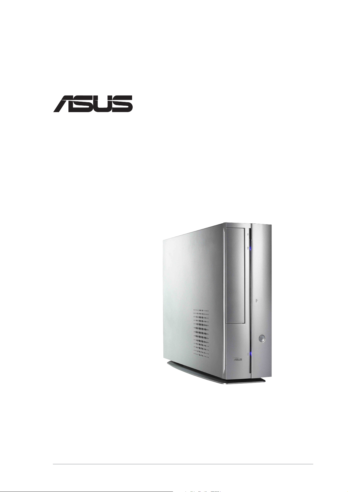
ASUS Book Size Barebone System
System Introduction
1-1
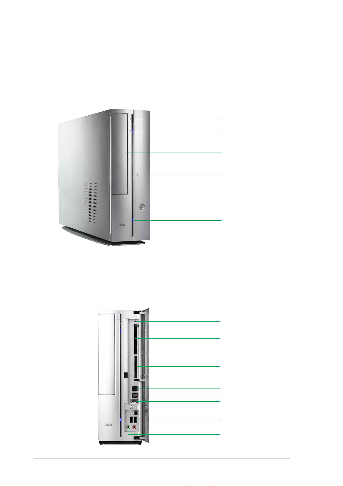
1.1 Front Panel Features
The ASUS Book Size Barebone System includes the ASUS motherboard,
a power supply and a CD-ROM or DVD drive built into in a dual-positional
chassis.
The front panel features:
CD/DVD Eject Button
HDD LED
CD-ROM / DVD Drive
I/O Panel,
(behind door,
press to open)
Power Button
Power LED
The front bezel door conceals the and features: a PCMCIA slot, 4-in-1
card slot, the fiber optical SPDIF in and out connectors, the 4 and 6-pin
1394 jacks, two USB connectors (Ports 2&3), headphone and microphone
connectors
Press PUSH icon to open the door.
Reset
PCMCIA
4-in-1 card reader
SPDIF in
SPDIF out
6-pin 1394
1-2
4-pin 1394
USB Ports (2&3)
Microphone
Headphone
Chapter 1: System Introduction
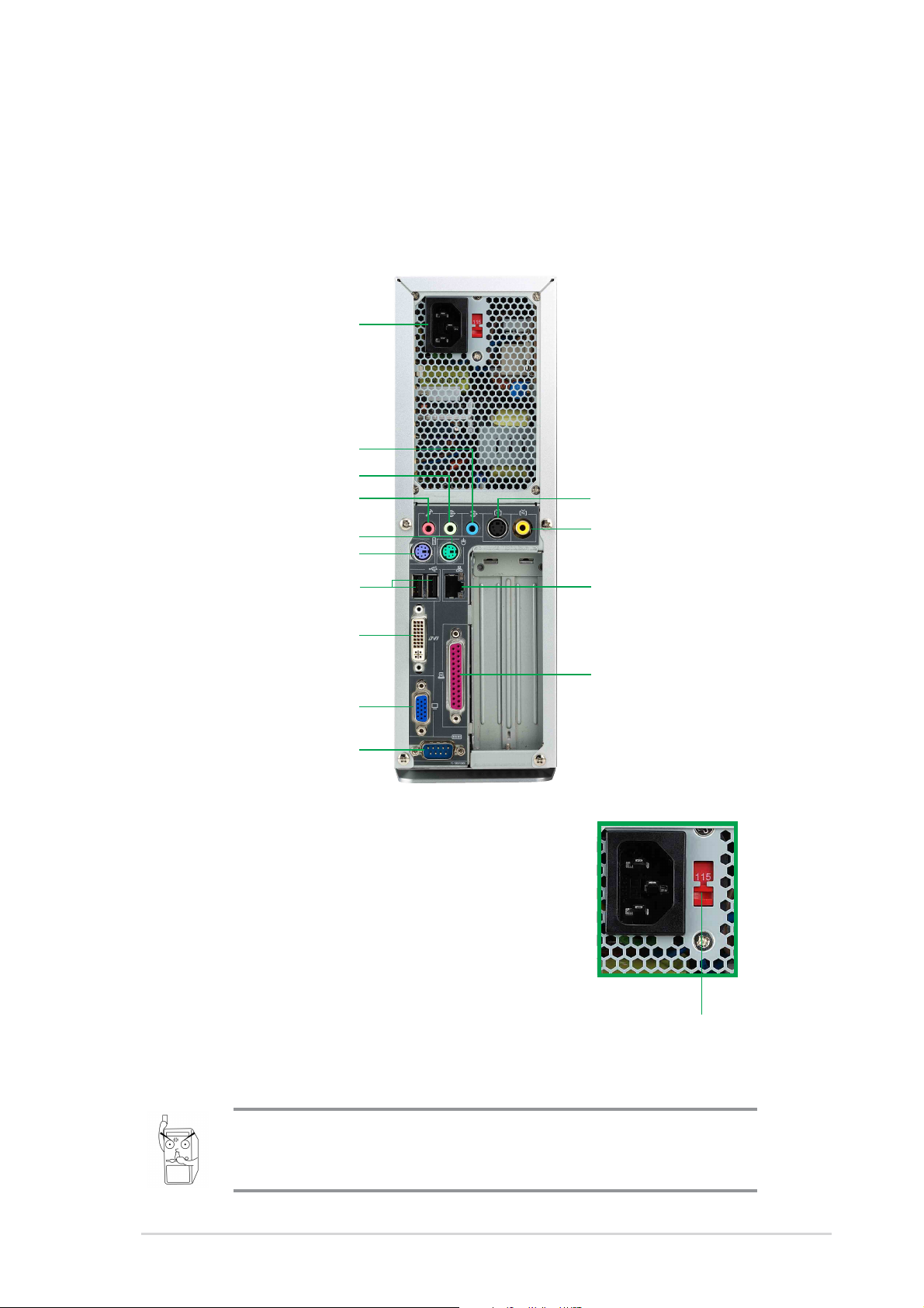
1.2 Rear Panel Features
The rear panel of the ASUS Book Size Barebone System includes the
standard PC99 I/O connectors for external devices, power supply socket,
and optional feature connectors.
The rear panel features:
Power Supply
Line In
Line Out
Microphone
S-Video
PS/2 Mouse
PS/2 Keyboard
USB (0&1)
DVI-Out
VGA Port
Serial Port
Voltage Selector
The switching power supply that came with
the system has a voltage selector switch
below the power socket. Use this switch to
select the appropriate voltage according to
the voltage supply in your area.
TV-Out
LAN Port
Parallel Port
If the voltage supply in your area is 100-127V,
set the switch to 115V.
If the voltage supply in your area is 200-240V,
set the switch to 230V.
Setting the switch to 115V in a 230V environment or 230V in a
115V environment will seriously damage the system!
ASUS Book Size Barebone System
115V/230V
Voltage Selector
1-3
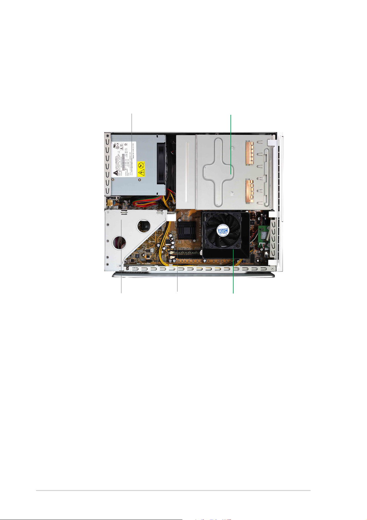
1.3 Internal Features
The figure below shows the system from above. The standard components
are already installed.
Power Supply
CD / DVD ROM Drive
PCI Riser Card
ASUS Motherboard
CPU Cooler
1-4
Chapter 1: System Introduction

Chapter 2
Step-by-step instructions on how to install basic
components.
ASUS has designed the Pundit for
an ASUS P4S8L motherboard only.
It is not advisable to install other
motherboards. Before installing
any motherboard other than the
original supplied by ASUS, make
sure that it fits into the case and
the I/O connectors correspond to
the openings on the back panel.
ASUS Book Size Barebone System
System Assembly
2-1
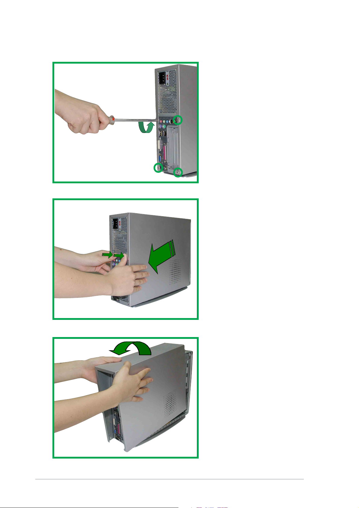
2.1 Opening the chassis
1. Remove the four screws
on each end of the back
panel. This frees the the
chassis cover.
2. Separate the case and
chassis cover: use your
thumbs to pull it off, from
the front to the back,
then lift it off the chassis.
2-2
3. Open the case, lifting
the top cover.
Chapter 2: System Assemby
5. Gently detach the three
front bezel hooks from
the case front so that it
may be removed.
6. Remove the front bezel
and set it aside.
ASUS Book Size Barebone System
2-3
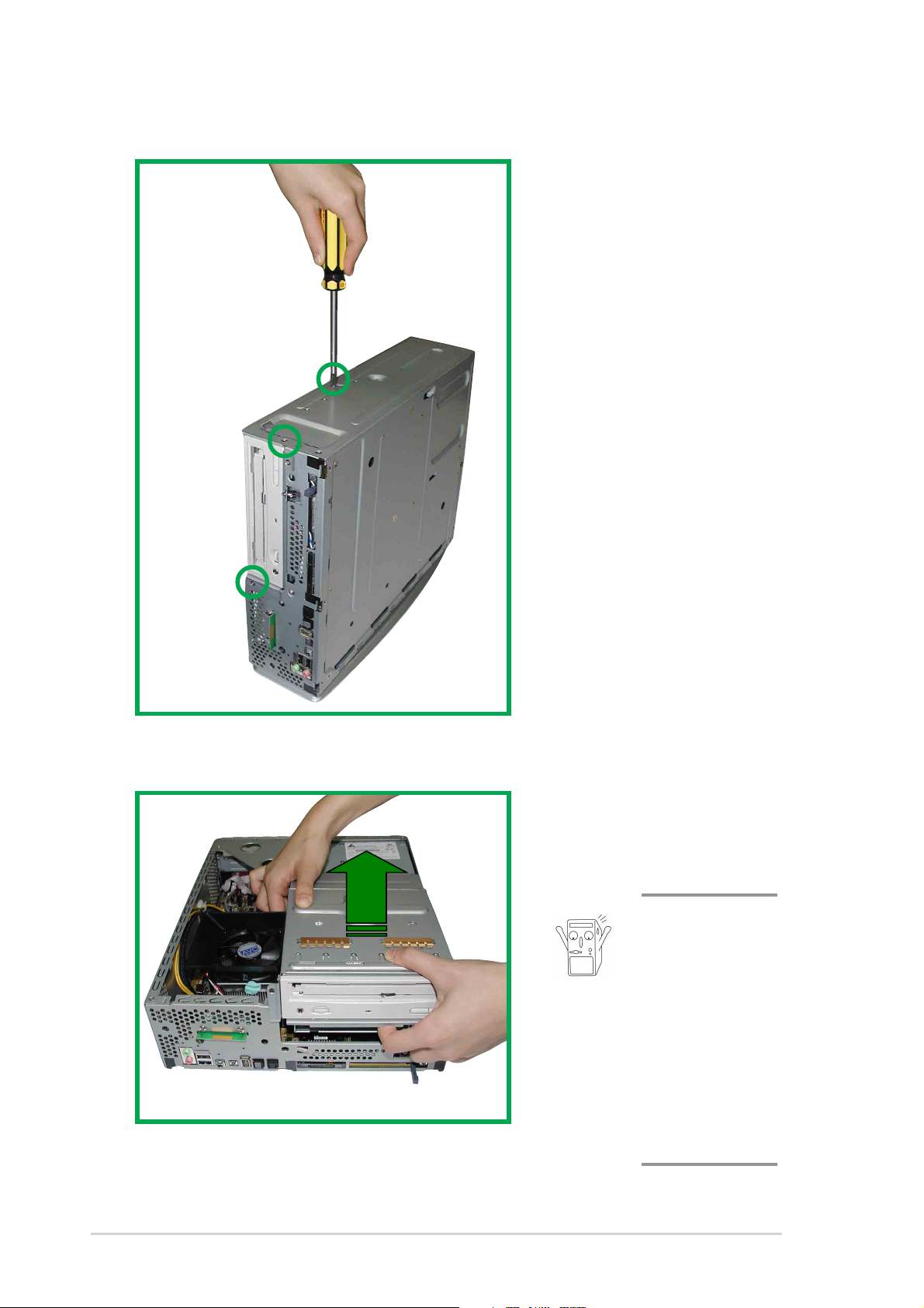
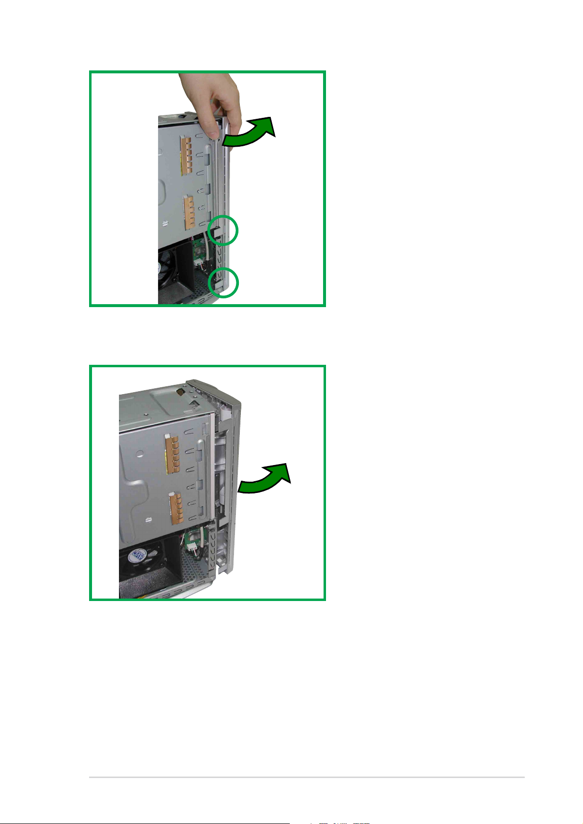
2.2 Removing the disk drive assembly
1. Remove the three
screws on each marked
location as shown. This
frees the DVD/CD/HD
drive assembly.
2. Slowly lift out the DVD/
CD/hard disk drive
module.
Take caution
when lifting out
the drive
assembly, you
may damage
the cables
connected to
the DVD/CD
and hard disk
drives.
2-4
Chapter 2: System Assemby
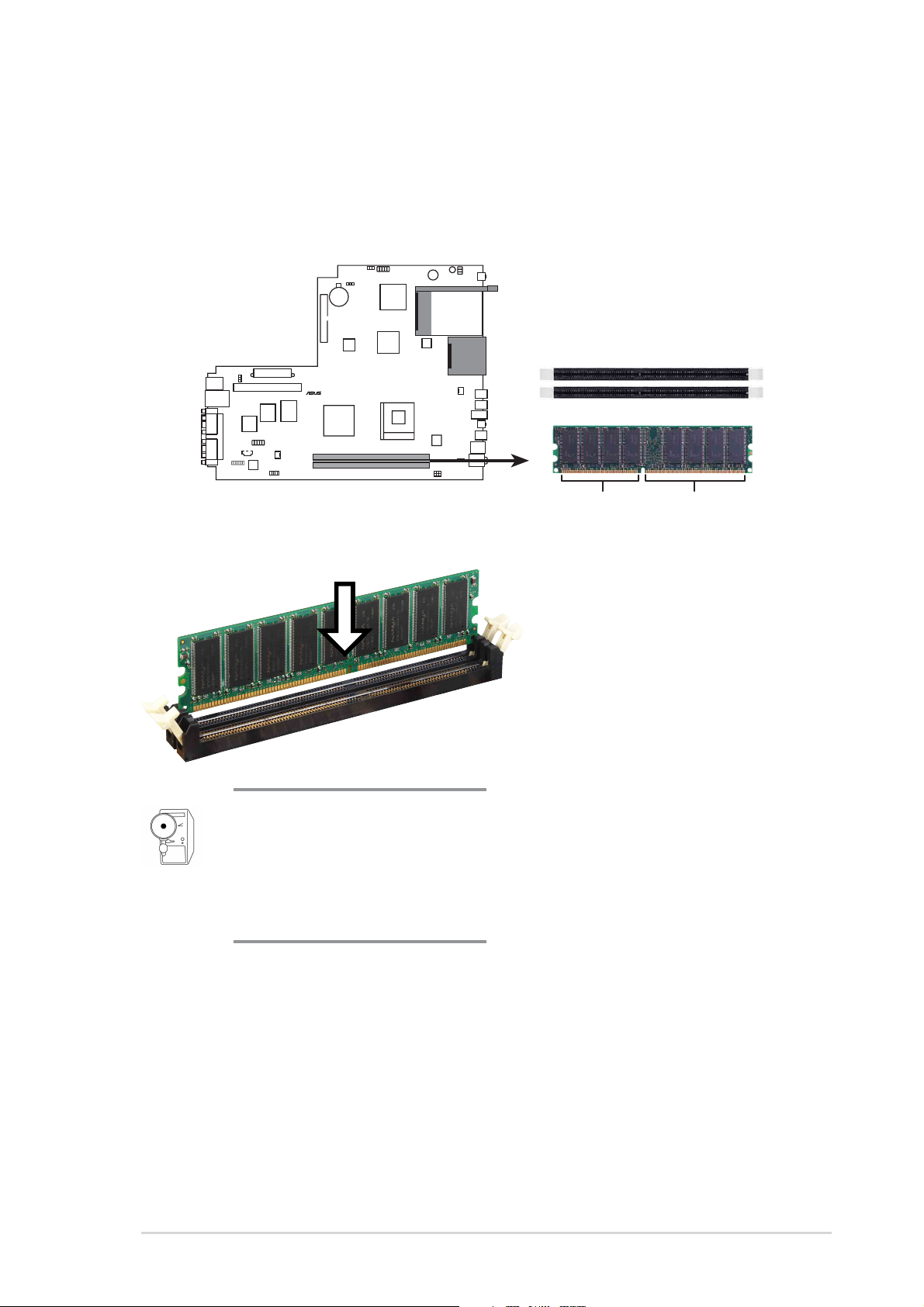
2.3 Installing the system memory
®
1. To perform this procedure, make sure
2 Locate the two DDR SDRAM DIMM sockets on the ASUS
motherboard.
P4S8L
P4S8L 184-Pin DDR DIMM Sockets
A DDR DIMM is keyed with a
notch so that it fits in only one
direction. DO NOT force a
DIMM into a socket to avoid
damaging the DIMM.
80 Pins 104 Pins
3. Unlock a DIMM socket
by pressing the retaining
clips outward.
4. Align a DIMM on the
socket such that the
notch on the DIMM
matches the break on
the socket.
5. Firmly insert the DIMM
into the socket until the
retaining clips snap back
in place and the DIMM is
properly seated.
6. After installing the
DIMM, place the CD and
floppy drive assembly
back into its original
position. Then, replace
the front bezel; take care
to insert the three plastic
tabs without stress.
ASUS Book Size Barebone System
2-5
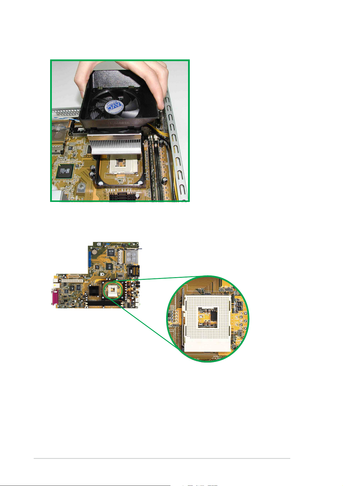
2.4 Installing the CPU
1. To install the CPU, it is
necessary to remove the
pre-installed heatsink
assembly.
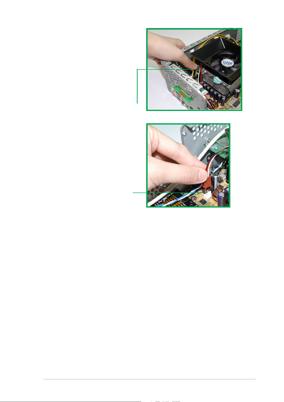
2. Press down and unhook
the metal retaining clips
on both sides of the
metal heatsink.
3. Disconnect the CPU fan
power cable if it is too
short.
4. Lift the heatsink
assembly up and out.
Pundit P4S8L Motherboard
5. Locate the CPU Socket
478 on the motherboard.
2-6
Chapter 2: System Assemby
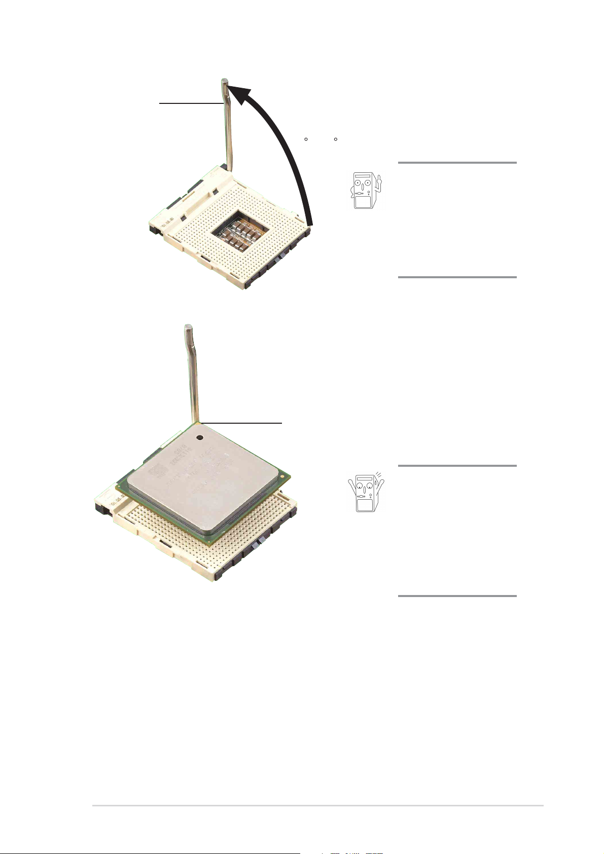
Socket Lever
0
6. Unlock the socket by
pressing the socket lever
sideways, then lift it up to
a 90°-100° angle.
90 -10
Make sure that the
socket lever is lifted
up to 90°-100° angle,
otherwise the CPU
does not fit in
completely.
7. Position the CPU above
the socket such that its
marked corner matches
the base of the socket
lever.
Gold Mark
into the socket until it fits
in place.
8. Carefully insert the CPU
The CPU fits only in
one correct
orientation. DO NOT
force the CPU into
the socket to prevent
bending the pins and
damaging the CPU!
9. When the CPU is in place, press it firmly on the socket while you push
down the socket lever to secure the CPU. The lever clicks on the side
tab to indicate that it is locked.
ASUS Book Size Barebone System
2-7
2.5 Installing the CPU heatsink and fan
The Intel® Pentium® 4 478/Northwood Processor requires a specially
designed heatsink and fan assembly to ensure optimum thermal condition
and performance.
When you buy a boxed Intel Pentium 4 478/Northwood Processor, the
package usually includes the heatsink and fan assembly.
Follow these steps to install the
CPU heatsink and fan.
1. Position the fan heatsink
assembly on top of the
installed CPU such that the
fan cable is nearest the CPU
fan connector on the
motherboard (marked
CPU_FAN1).
2. Align one retention bracket
with the rail on the side of the
heatsink. Orient the bracket
such that the locking lever is
on the side of the PCI slots.
3. Snap the hook of the metal
retention bracket into the hole
of the retention module.
4. Follow steps 2 and 3 to attach
the second retention bracket.
Retention bracket
Locking lever
Hole on the retention module
2-8
Chapter 2: System Assemby
5. Carefully press down the
locking lever on the other side
of the bracket and hook its end
into the hole of the retention
module to secure the fan
heatsink assembly in place.
6. Follow step 5 to lock the
second bracket.
Locking lever
7. Connect the CPU fan cable
from the assembly to the fan
connector labeled CPU_FAN1.
CPU fan connector
(CPU_FAN1)
ASUS Book Size Barebone System
2-9
2.6 Install a CD/DVD-ROM drive
In the future, you may want to upgrade your CD/DVD-ROM drive for higher
speed. Follow these steps to install a CD/DVD-ROM drive.
1. After dislodging the disk drive assembly and disconnecting all cable
connections, place disk drive assembly on a stable surface.
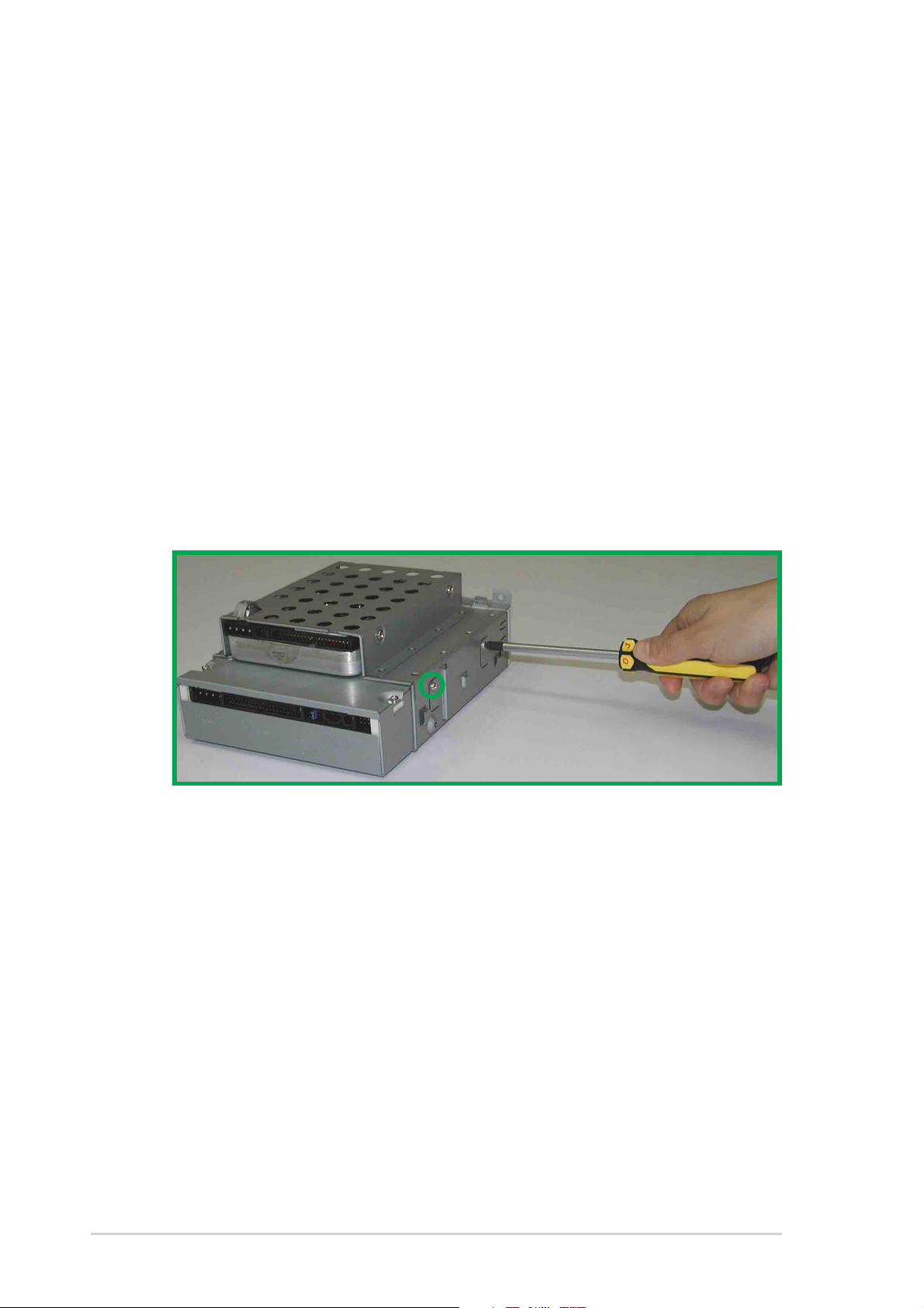
2. If you are replacing an installed CD/DVD-ROM drive, first remove the
four screws (two on each side) to dislodge currently installed drive.
3. Slide the new CD/DVD-ROM drive in the vacated CD/DVD-ROM
drive slot. Properly match the screw holes on each side of the drive. If
the screw holes doesn’t match, pull the drive out and reverse the
drive entry.
4. After properly matching the screw holes, tighten the four screws (two
on each side). Make sure the drive is stable in place.
2-10
Chapter 2: System Assemby
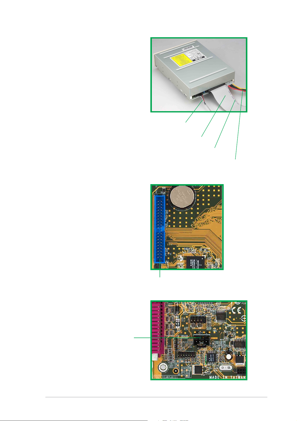
5. Connect a power cable from
the power supply to the power
connector at the back of the
CD/DVD-ROM. Use the cable
with the white connector
labeled P4.
6. Connect one end of the IDE
ribbon cable to the IDE
interface at the back of the
CD-ROM, matching the red
stripe on the cable with Pin 1
on the IDE interface.
CD/DVD-ROM Audio
Cable
IDE Ribbon Cable
7. Connect one end of the
CD-ROM audio cable to the
4-pin connector at the back of
the CD/DVD-ROM.
8. Connect the other end of the
IDE ribbon cable to the
primary IDE connector (blue
connector labeled PRI_IDE2)
on the motherboard.
Red Stripe to Pin 1
Power Cable (P4)
Primary IDE connector
(PRI_IDE1)
9. Connect the other end of the
audio cable to the black 4-pin
connector labeled CD on the
motherboard.
CD/DVD-ROM
Connector
(CD1)
ASUS Book Size Barebone System
2-11
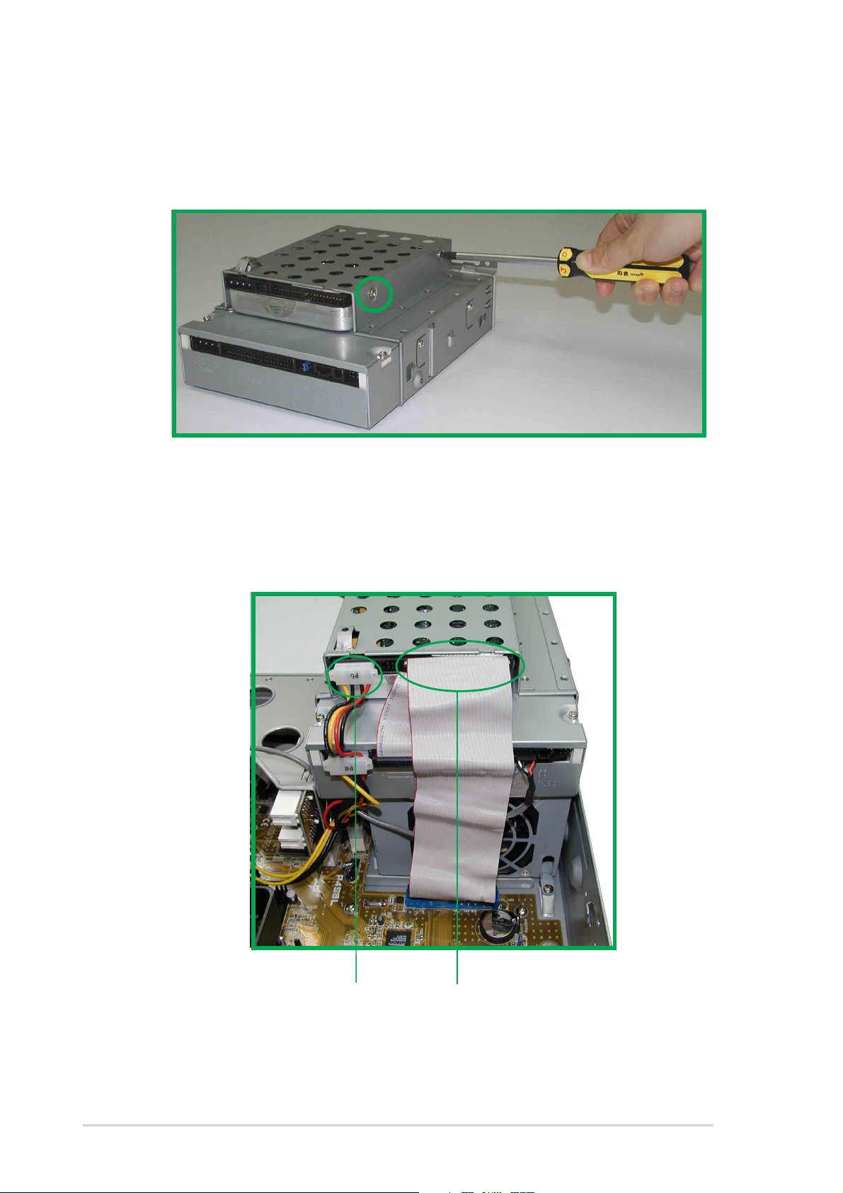
2.7 Installing a hard disk drive
1. Carefully slip the hard disk drive into the disk drive assembly. Ensure
that the four screw holes are properly aligned. Tighten in the screws.
2. Slide the disk drive assembly back into its original place. Connect the
middle connector of the IDE cable to the primary IDE connector on
the hard disk drive. Locate the P5 power cable and connect it to the
hard disk drive.
2-12
Power Cable (P5)
IDE Cable
(Red strip to Pin 1)
Chapter 2: System Assemby
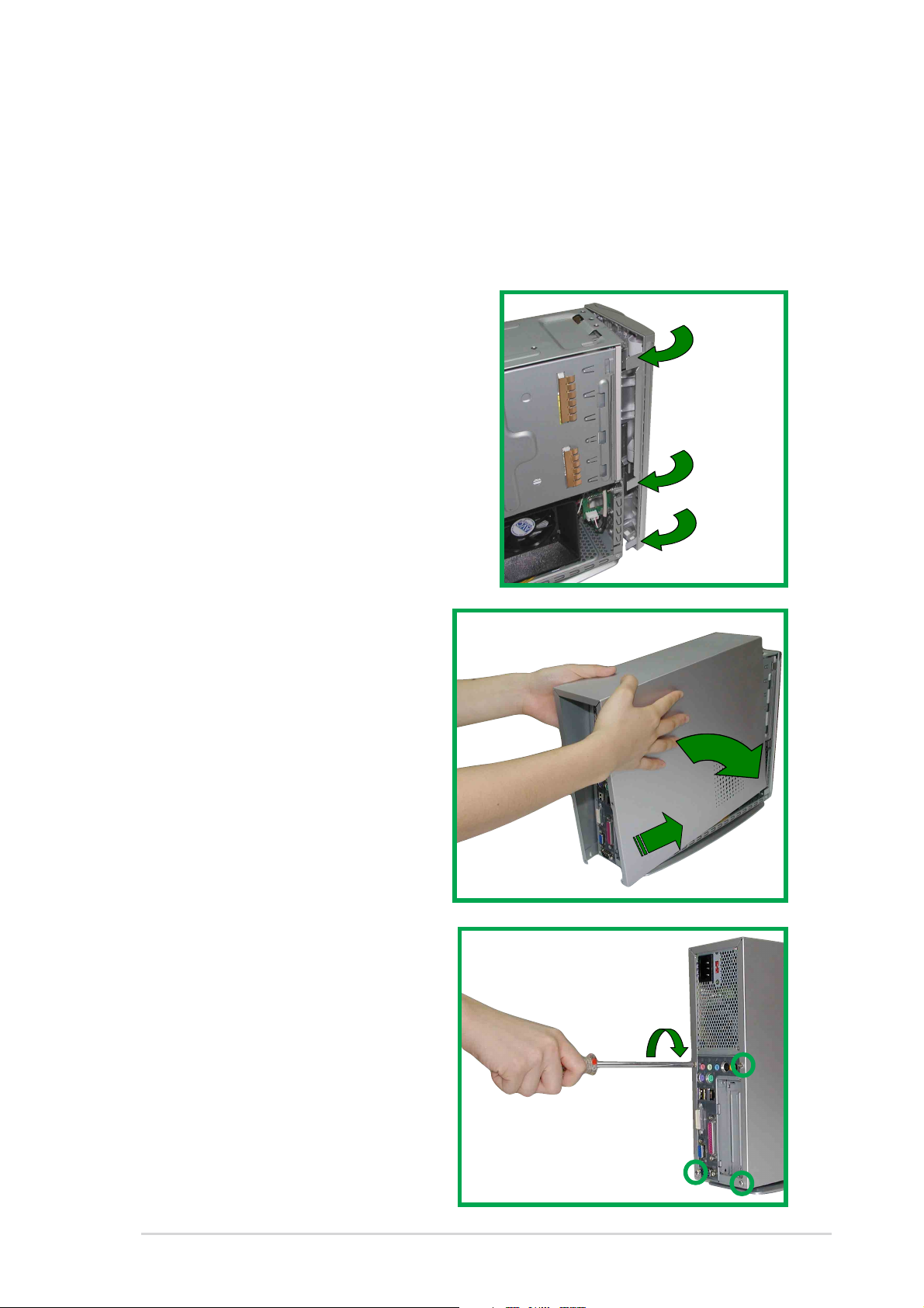
2.8 Replace the cover
After you have installed all the internal components and you have
connected all the necessary cables, you are now ready to put the system
back together.
Follow these steps to re-assemble
the system.
1. Replace the front cover bezel.
Make sure the front bezel
locks are properly clamped in
place.
2. Align chassis cover tabs and
push chassis cover towards
the front panel.
3. Make sure the four screw
holes on the chassis cover are
aligned to the holes on the
case.
4. Tighten the four screws.
ASUS Book Size Barebone System
2-13
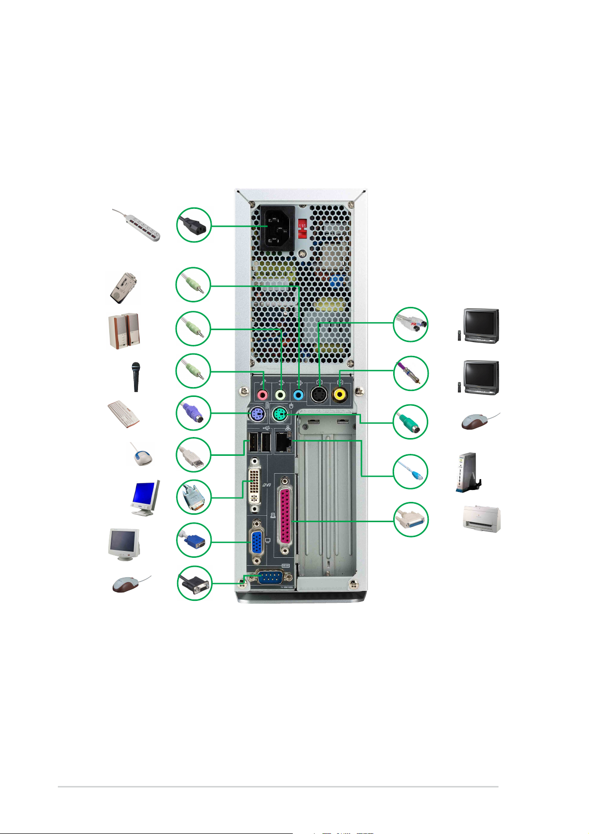
2.9 Connect External Devices
The figure below shows the specific connectors and devices that you can
connect to the rear panel ports.
AC
Line In
Line Out
Mic
PS/2 KB
USB
DVI
VGA
Serial
S-Video
TV-out
PS/2 Mouse
RJ-45
Parallel
2-14
Chapter 2: System Assemby
2.10 Power Supply Specifications
2.10.1 Input Characteristics
Input Voltage Range Min Nom Max
Range 1 90V 115V 135V
Range 2 180V 230V 265V
Input Frequency Range 47 Hz to 63 Hz
Maximum Input ac Current 4A max. at 115Vac
2A max. at 230Vac, maximum load
Inrush Current 90A max. at 115Vac,
full load cold start at 25°C
Efficiency 70% min. at nominal input,
maximum load
2.10.2 Output Characteristics
Output
Voltage Min Max Min Max Max
+5V 0.5A 4.0A -5% +5% 50mVp-p
+12V 0.45A 9.5A -5% +5% 120mVp-p
-12V 0A 0.2A -10% +10% 120mVp-p
+5VSB 0.05A 1.5A -5% +5% 50mVp-p
+3V3 1A 8.0A -5% +5% 50mVp-p
Load Range Regulation Ripple
2.10.3 Over-Voltage Protection (OVP)
Output Voltage Maximum Voltage
+5V 6.5V
+12V 15.6V
+3.3V 4.3V
The power supply will shut down and latch off for shorting +5V,
+12V, -12V, or +3.3V. By shorting +5VSB, the power supply can
latch down or automatically recover when the fault condition is
removed
ASUS Book Size Barebone System
2-15

2-16
Chapter 2: System Assemby
 Loading...