How it Works
Log In / Sign Up
Buy Points
How it Works
FAQ
Contact Us
Questions and Suggestions
Users
ASUS
Loading...
P
PRIME-B250M-PLUS
PRIME-B250-PLUS
Prime B365M-CCSM
Prime B365M-K
Prime B450M-A
3
Prime B450M-A II
2
Prime B450M-K
3
Prime B450M-K II
2
Prime B450-Plus
3
Prime B460-I Plus
2
Prime B460M-A
2
PRIME B460M-AJ
2
Prime B460M-K
2
Prime B460-Plus
2
Prime B550M-A
2
Prime B550M-A [WI-FI]
2
Prime B550M-K
2
Prime B550-Plus
2
PRIME H270
PRIME H270M-PLUS/CSM
5
Prime H270-Plus
2
Prime H310I-Plus
Prime H310I-Plus R2.0
2
PRIME H310M2 R2.0/FPT II
Prime H310M-A R2.0
2
Prime H310M-C
Prime H310M-C R2.0
Prime H310M-D
2
Prime H310M-D R2.0
Prime H310M-E
2
PRIME H310M-E/BR
Prime H310M-E R2.0
2
PRIME H310M-E R2.0/BR
Prime H310M-K R2.0
PRIME H310M-R R2.0
Prime H310-Plus R2.0
Prime H310T
Prime H370M-Plus
2
Prime H370-Plus
Prime H410I-Plus
Prime H410M-A
2
Prime H410M-D
2
Prime H410M-E
2
Prime H410M-K
2
PRIME H410M-R
2
Prime H470M-Plus
2
Prime H470-Plus
2
PRIME J3355I-C
Prime J4005I-C
PRIME J4005I-C/BR
PRIME-Q270M-C
2
PRIME TRX40-PRO
Prime TRX40-Pro S
2
Prime X299-A
Prime X299-A II
Prime X299-Deluxe
2
Prime X299-Deluxe II
2
Prime X299 Edition 30
prime x370-a
Prime X370-Pro
Prime X399-A
PRIME X470-PRO
Prime X570-P
2
Prime X570-Pro
PRIME Z270-A
PRIME Z270-AR
11
Prime Z270M-Plus
2
PRIME Z270M-PLUS/BR
5
Prime Z270-P
2
Prime Z370-P
Prime Z370-P II
Prime Z390-A
4
Prime Z390M-Plus
2
Prime Z390-P
Prime Z490-A
2
Prime Z490M-Plus
2
Prime Z490-P
2
Prime Z490-V
2
PRL-DL
PRL-DLS
PRL-DLS533
PRO 2300
PRO 32
27
PRO 35
PRO 36
2
PRO 36S
22
PRO 5
21
PRO 7
21
PRO 8
18
Pro A520M-C
2
Pro B460M-C
2
PRO B53A
Pro D641SC-I39100030R
Pro E500 G6
PRO H310M-R R2.0 WI-FI
PRO H310M-R R2.0 WI-FI/CSM
Pro H410M-C
2
Pro H410T
2
Pro P1440FA-FA1476R
Pro P1510CJA-BQ418R
Loading...
Loading...
Nothing found
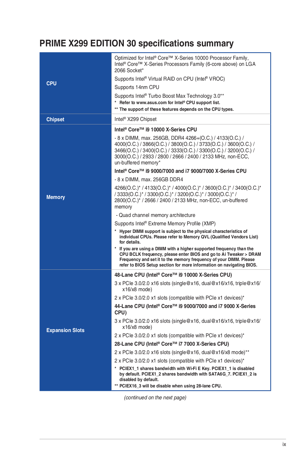
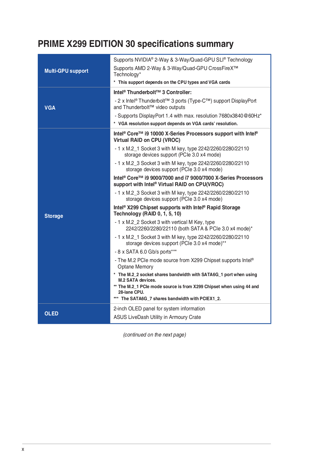
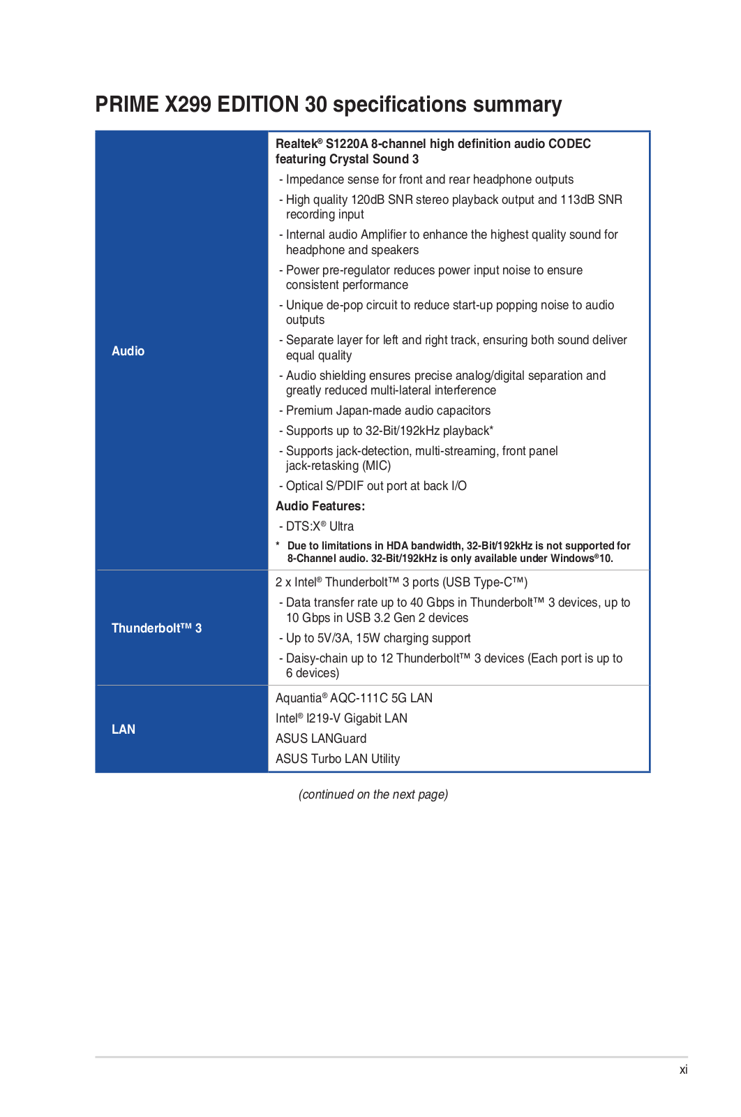
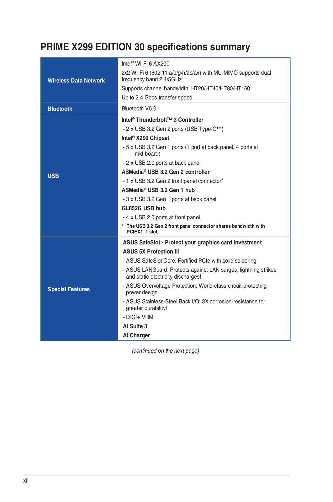
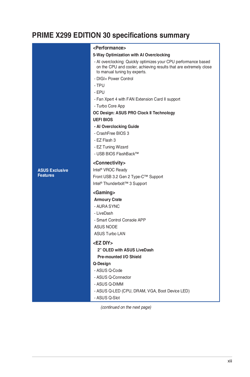
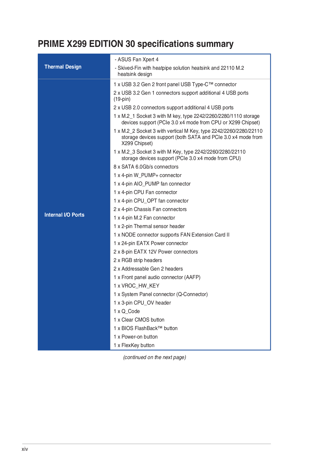
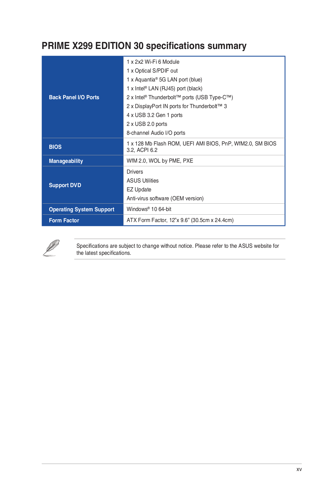
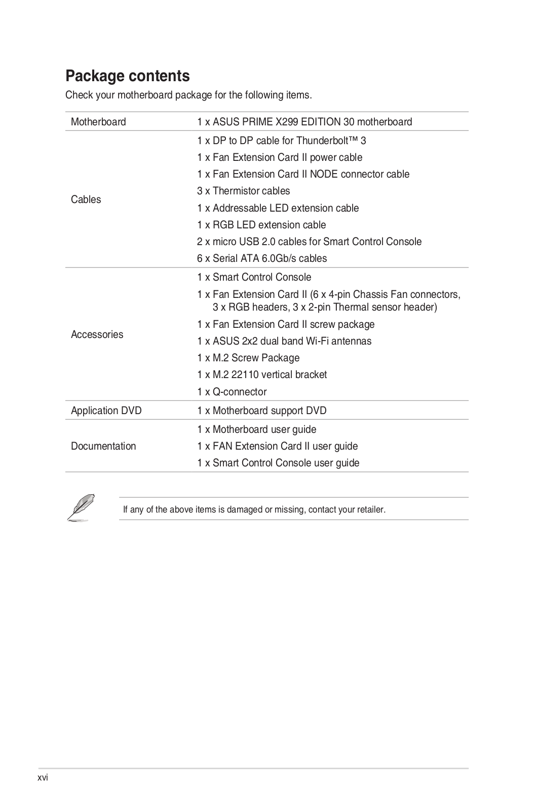
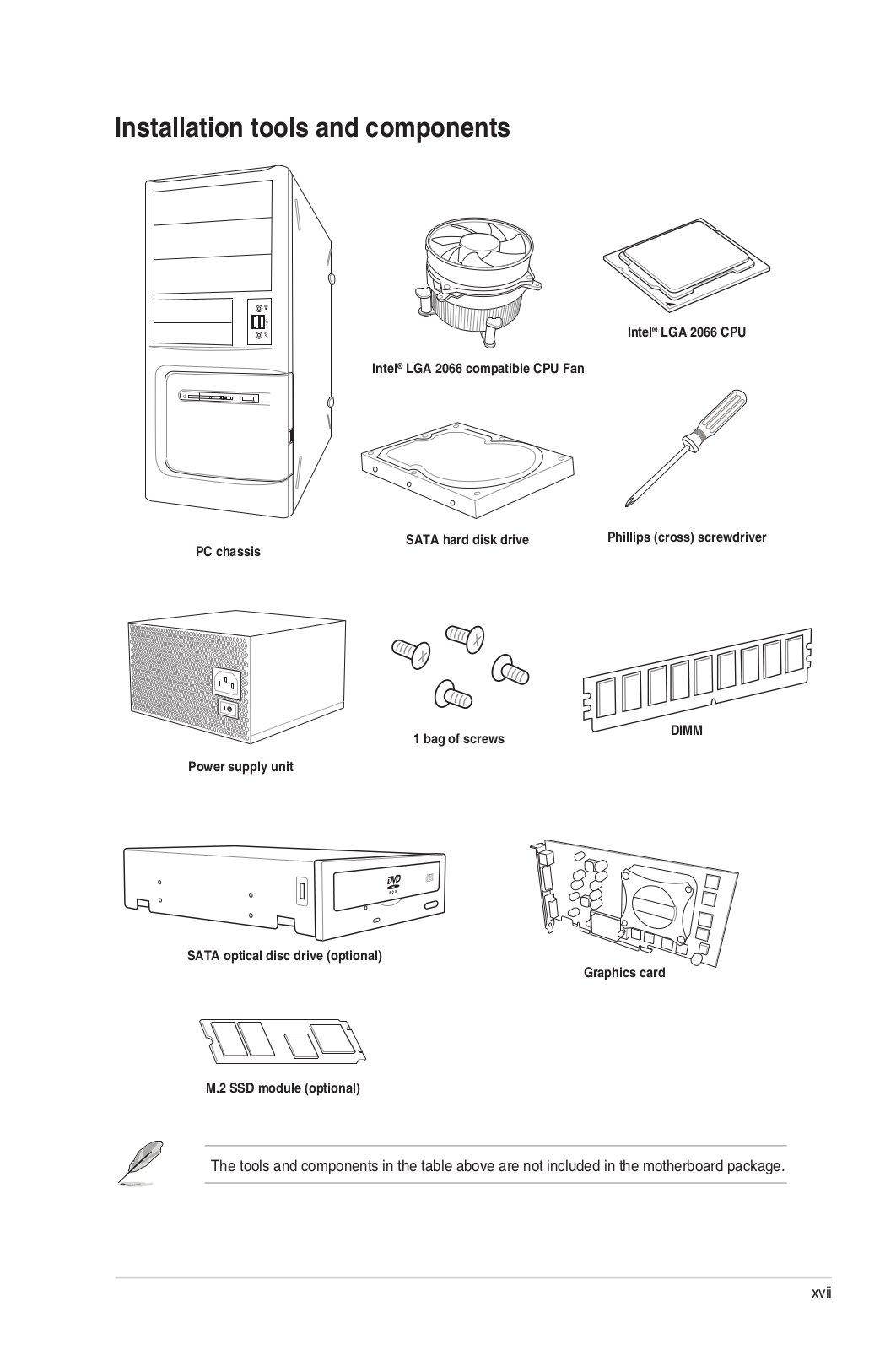
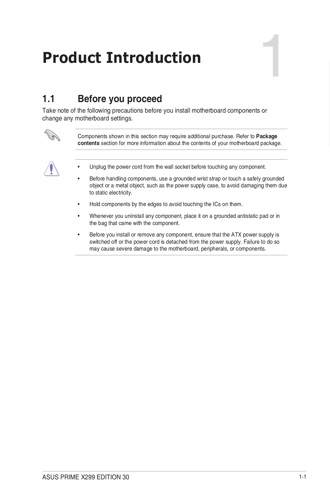
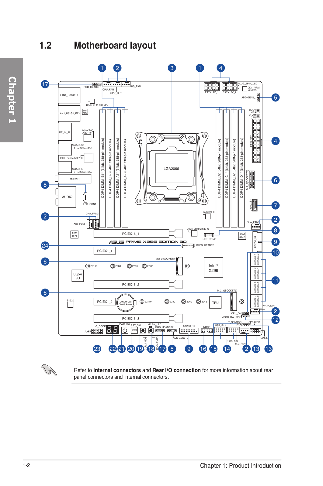
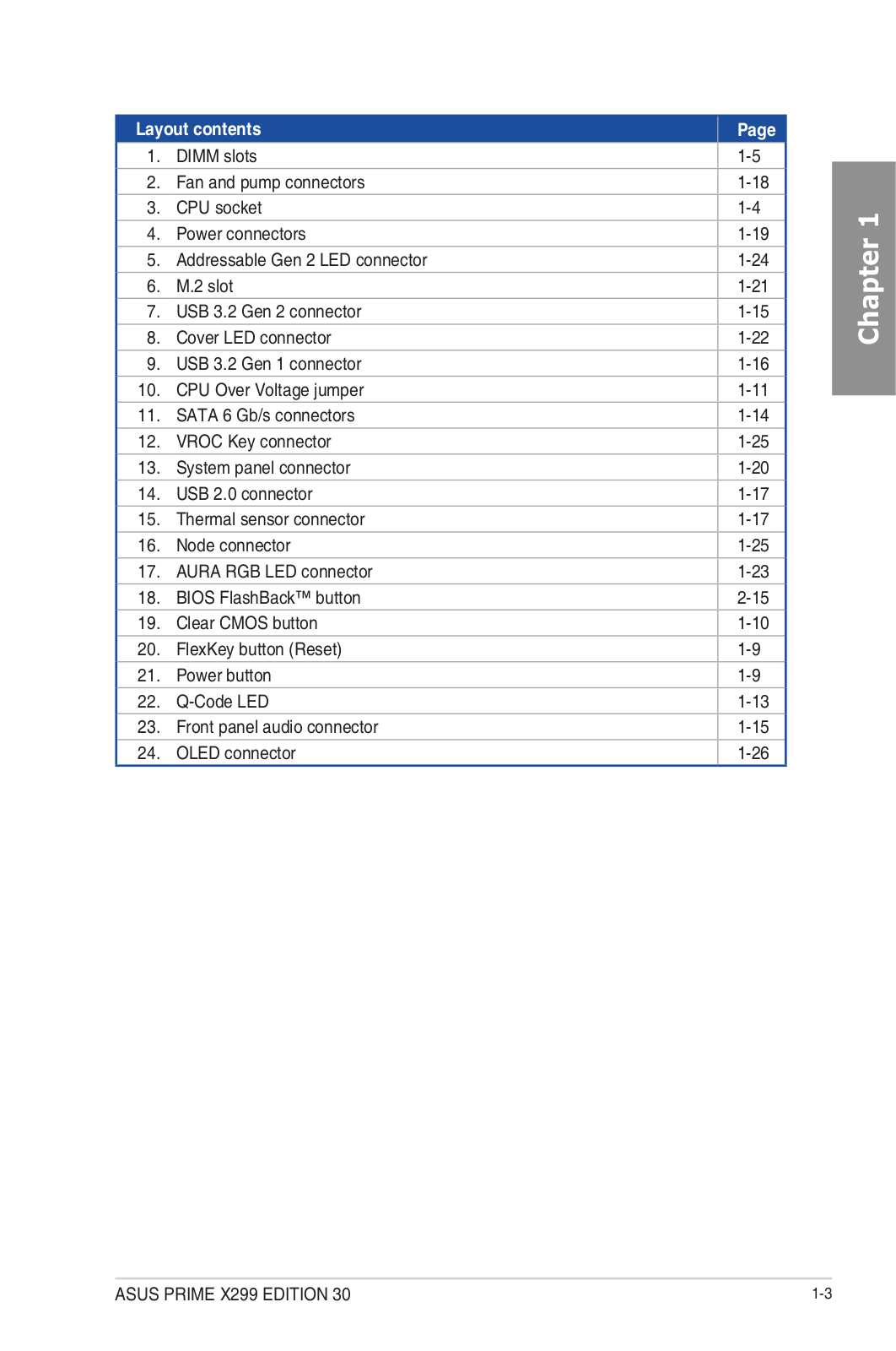
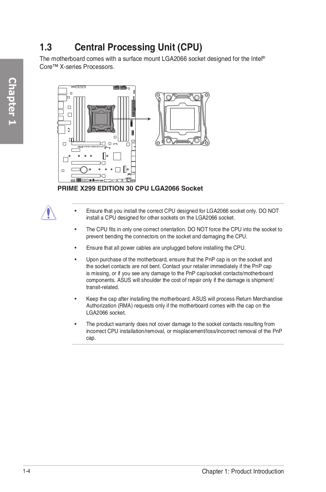
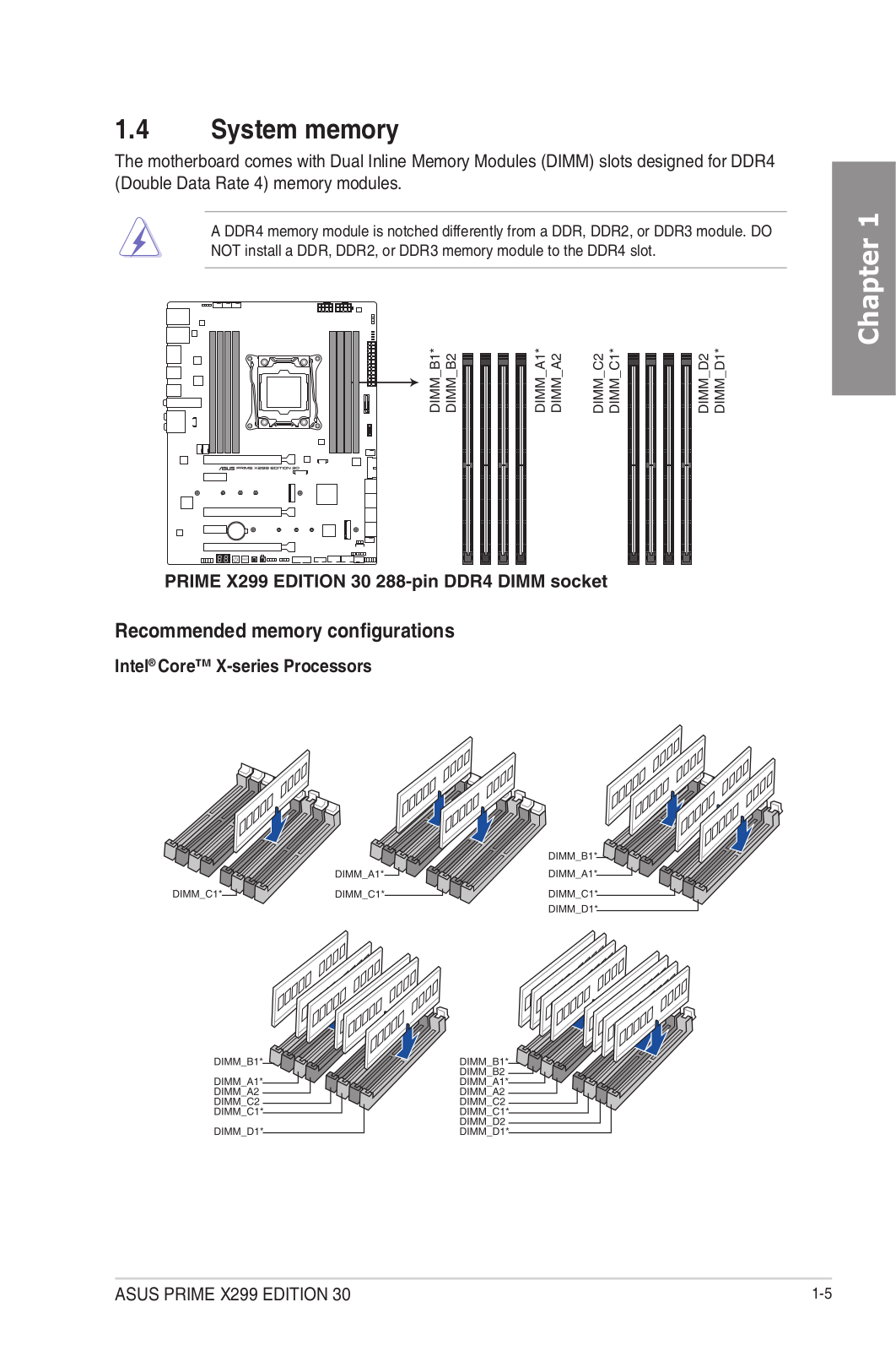
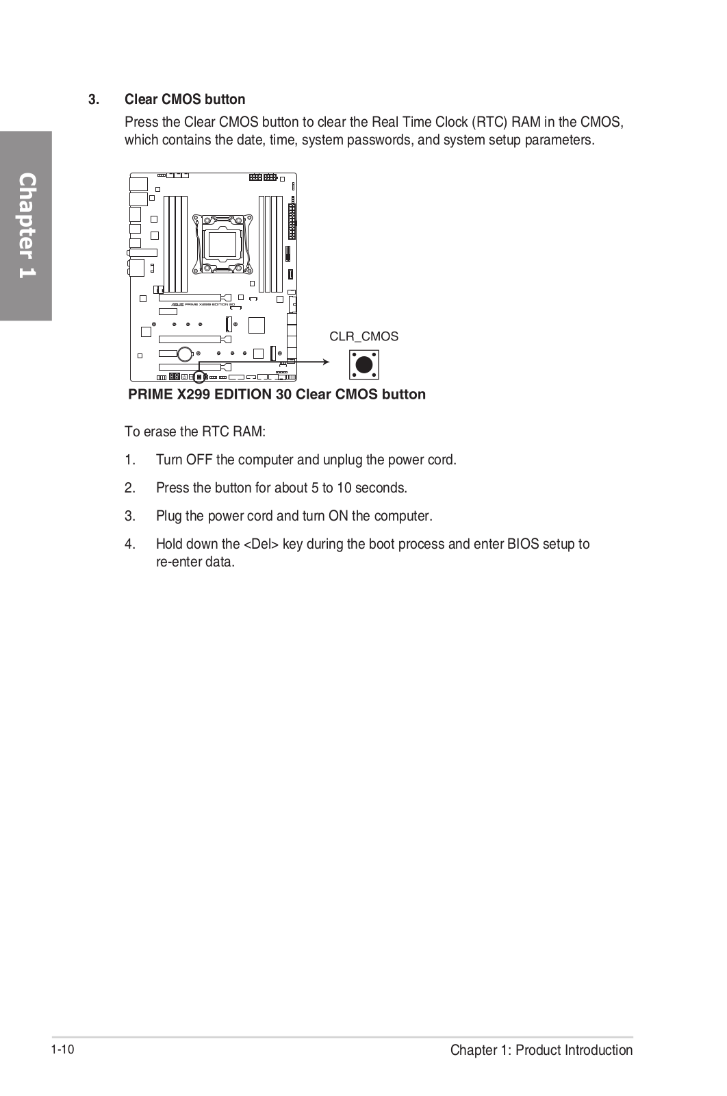
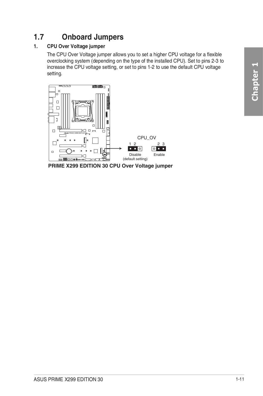
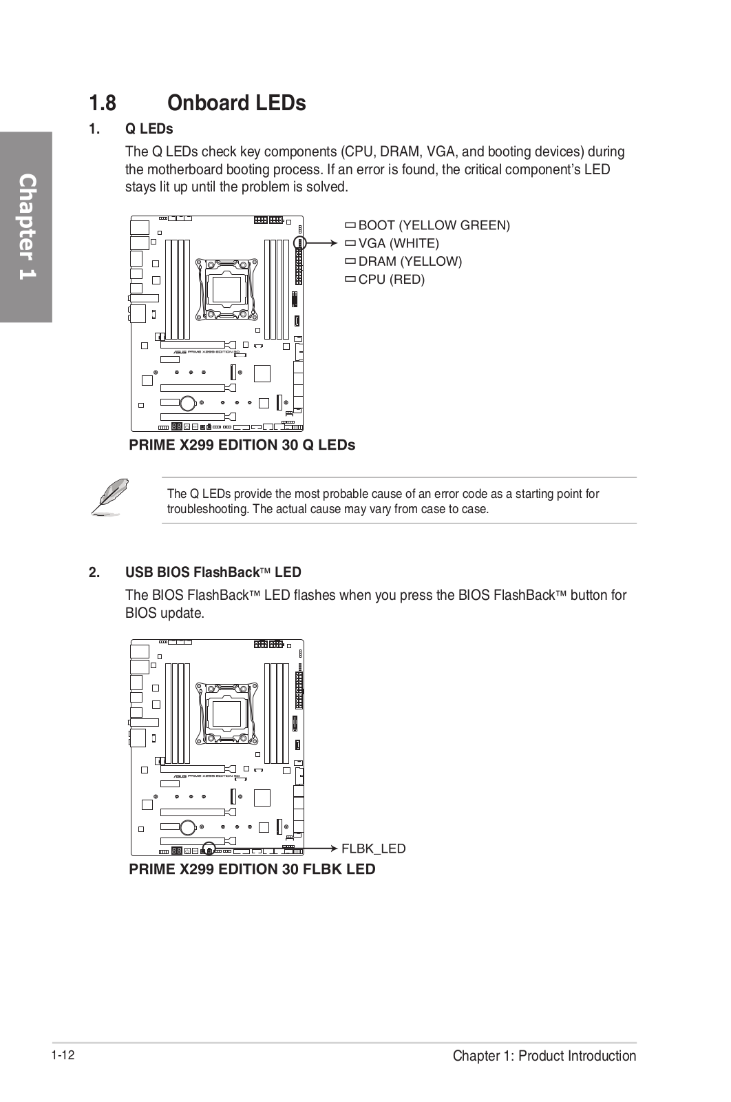
Prime X299 Edition 30
Service Manual
110 pgs
9.59 Mb
0
Table of contents
Loading...
ASUS Prime X299 Edition 30 Service Manual
...
ASUS Service Manual
Download
Specifications and Main Features
Frequently Asked Questions
User Manual
Download
Loading...
+
80
hidden pages
Unhide
You need points to download manuals.
1 point = 1 manual.
You can buy points or you can get point for every manual you upload.
Buy points
Upload your manuals
 Loading...