

Page 1
PIKE 2308
LSISAS RAID card
User Guide
Page 2

E8142
First Edition
March 2013
Copyright © 2013 ASUSTeK COMPUTER INC. All Rights Reserved.
No part of this manual, including the products and software described in it, may be reproduced,
transmitted, transcribed, stored in a retrieval system, or translated into any language in any form or by any
means, except documentation kept by the purchaser for backup purposes, without the express written
permission of ASUSTeK COMPUTER INC. (“ASUS”).
Product warranty or service will not be extended if: (1) the product is repaired, modied or altered, unless
such repair, modication of alteration is authorized in writing by ASUS; or (2) the serial number of the
product is defaced or missing.
ASUS PROVIDES THIS MANUAL “AS IS” WITHOUT WARRANTY OF ANY KIND, EITHER EXPRESS
OR IMPLIED, INCLUDING BUT NOT LIMITED TO THE IMPLIED WARRANTIES OR CONDITIONS OF
MERCHANTABILITY OR FITNESS FOR A PARTICULAR PURPOSE. IN NO EVENT SHALL ASUS, ITS
DIRECTORS, OFFICERS, EMPLOYEES OR AGENTS BE LIABLE FOR ANY INDIRECT, SPECIAL,
INCIDENTAL, OR CONSEQUENTIAL DAMAGES (INCLUDING DAMAGES FOR LOSS OF PROFITS,
LOSS OF BUSINESS, LOSS OF USE OR DATA, INTERRUPTION OF BUSINESS AND THE LIKE),
EVEN IF ASUS HAS BEEN ADVISED OF THE POSSIBILITY OF SUCH DAMAGES ARISING FROM ANY
DEFECT OR ERROR IN THIS MANUAL OR PRODUCT.
SPECIFICATIONS AND INFORMATION CONTAINED IN THIS MANUAL ARE FURNISHED FOR
INFORMATIONAL USE ONLY, AND ARE SUBJECT TO CHANGE AT ANY TIME WITHOUT NOTICE,
AND SHOULD NOT BE CONSTRUED AS A COMMITMENT BY ASUS. ASUS ASSUMES NO
RESPONSIBILITY OR LIABILITY FOR ANY ERRORS OR INACCURACIES THAT MAY APPEAR IN THIS
MANUAL, INCLUDING THE PRODUCTS AND SOFTWARE DESCRIBED IN IT.
Products and corporate names appearing in this manual may or may not be registered trademarks or
copyrights of their respective companies, and are used only for identication or explanation and to the
owners’ benet, without intent to infringe.
ii
Page 3

Contents
About this guide .........................................................................................................iv
PIKE 2308 specications summary .......................................................................... vi
Chapter 1: Product
introduction
1.1 Welcome! .................................................................................................... 1-2
1.2 Package contents.......................................................................................1-2
1.3 Card layout .................................................................................................1-3
1.4 System requirements.................................................................................1-3
1.5 Card installation ......................................................................................... 1-4
Chapter 2: RAID conguration
2.1 Setting up RAID ..........................................................................................2-2
2.1.1 RAID denitions .......................................................................... 2-2
2.1.2 Installing hard disk drives ............................................................ 2-2
2.2 LSI Corporation MPT Setup Utility ...........................................................2-3
2.2.1 RAID 1 volume ............................................................................ 2-4
2.2.2 RAID 1E/10 volume.....................................................................2-8
2.2.3 RAID 0 volume .......................................................................... 2-10
2.2.4 Managing Arrays .......................................................................2-12
2.2.5 Viewing SAS topology ............................................................... 2-19
2.2.6 Global Properties ...................................................................... 2-20
2.3 MegaRAID Storage Manager ................................................................... 2-23
2.3.1 Hardware and Software Requirements ..................................... 2-23
2.3.2 Installing MegaRAID Storage Manager Sofware on
Microsoft Windows OS .............................................................. 2-23
2.3.3 Installing MegaRAID Storage Manager Sofware for Linux........2-27
2.3.4 Linux Error Messages ............................................................... 2-28
2.3.5 Starting MegaRAID Storage Manager Software ....................... 2-29
2.3.6 MegaRAID Storage Manager Window ...................................... 2-31
Chapter 3: Driver installation
3.1 RAID driver installation .............................................................................3-2
3.1.1 Creating a RAID driver disk.........................................................3-2
3.1.2 Windows® Server 2003 OS ......................................................... 3-4
3.1.3 Red Hat® Enterprise Linux OS 5 ................................................. 3-9
3.1.4 SUSE Linux OS 11 .................................................................... 3-11
ASUS contact information ..................................................................................... 3-12
iii
Page 4

About this guide
This user guide contains the information you need when installing and conguring the server
management board.
How this guide is organized
This guide contains the following parts:
• Chapter 1: Product introduction
This chapter offers the PIKE 2308 SAS RAID card features and the new technologies
it supports.
• Chapter 2: RAID conguration
This chapter provides instructions on setting up, creating, and conguring RAID sets
using the available utilities.
• Chapter 3: Driver installation
This chapter provides instructions for installing the RAID drivers on different operating
systems.
Where to nd more information
Refer to the following sources for additional information and for product and software
updates.
1. ASUS websites
The ASUS website provides updated information on ASUS hardware and software
products. Refer to the ASUS contact information.
2. Optional documentation
Your product package may include optional documentation, such as warranty yers,
that may have been added by your dealer. These documents are not part of the
standard package.
iv
Page 5
Conventions used in this guide
To make sure that you perform certain tasks properly, take note of the following symbols used
throughout this manual.
DANGER/WARNING: Information to prevent injury to yourself
when trying to complete a task.
CAUTION: Information to prevent damage to the components
when trying to complete a task.
IMPORTANT: Instructions that you MUST follow to complete a
task.
NOTE: Tips and additional information to help you complete a
task.
Typography
Bold text Indicates a menu or an item to select.
Italics
Used to emphasize a word or a phrase.
<Key> Keys enclosed in the less-than and greater-than sign means
that you must press the enclosed key.
Example: <Enter> means that you must press the Enter or
Return key.
<Key1+Key2+Key3> If you must press two or more keys simultaneously, the key
names are linked with a plus sign (+).
Example: <Ctrl+Alt+D>
Command Means that you must type the command exactly as shown,
then supply the required item or value enclosed in
brackets.
Example: At the DOS prompt, type the command line:
format a:
v
Page 6
PIKE 2308 specications summary
Controller LSISAS2308
Interface ASUS PIKE interface
Ports 8 ports
Support device SAS/SAS II devices
SATA/SATA II/SATA III devices
Data transfer rate SATA III and SAS II 6Gb/s per PHY
RAID level RAID 0/RAID 1/RAID 1E/RAID 10
OS support* Windows® Server 2012
Windows® Server 2008 Enterprise R2
Windows® Server 2003 Enterprise R2
Windows® 8
Windows® 7 Ultimate
Red Hat Enterprise Linux AS 5.8
Red Hat Enterprise Linux AS 6.3
SuSE Linux Enterprise Server 10.4
SuSE Linux Enterprise Server 11.2
CentOS 6.2
Fedora 17
Form factor 6.44 in x 1.57 in (1U compatible)
* The exact OS support would base on the OS support list of the motherboard.
** Specications are subject to change without notice.
vi
Page 7

This chapter offers the PIKE 2308 SAS RAID card
features and the new technologies it supports.
Chapter 1: Product
introduction
1
Page 8

1.1 Welcome!
Thank you for buying an ASUS® PIKE 2308 SAS RAID card!
The ASUS PIKE 2308 allows you to create RAID 0, RAID 1, RAID 1E, and RAID 10 sets from
SATA/SATA II/SATA III/SAS/SAS II hard disk drives connected to the SAS connectors on the
motherboard.
Before you start installing the RAID card, check the items in your package with the list below.
1.2 Package contents
Check your package for the following items.
• ASUS PIKE 2308 SAS RAID card
• Support CD
• User guide
If any of the above items is damaged or missing, contact your retailer.
1-2
Chapter 1: Product introduction
Page 9
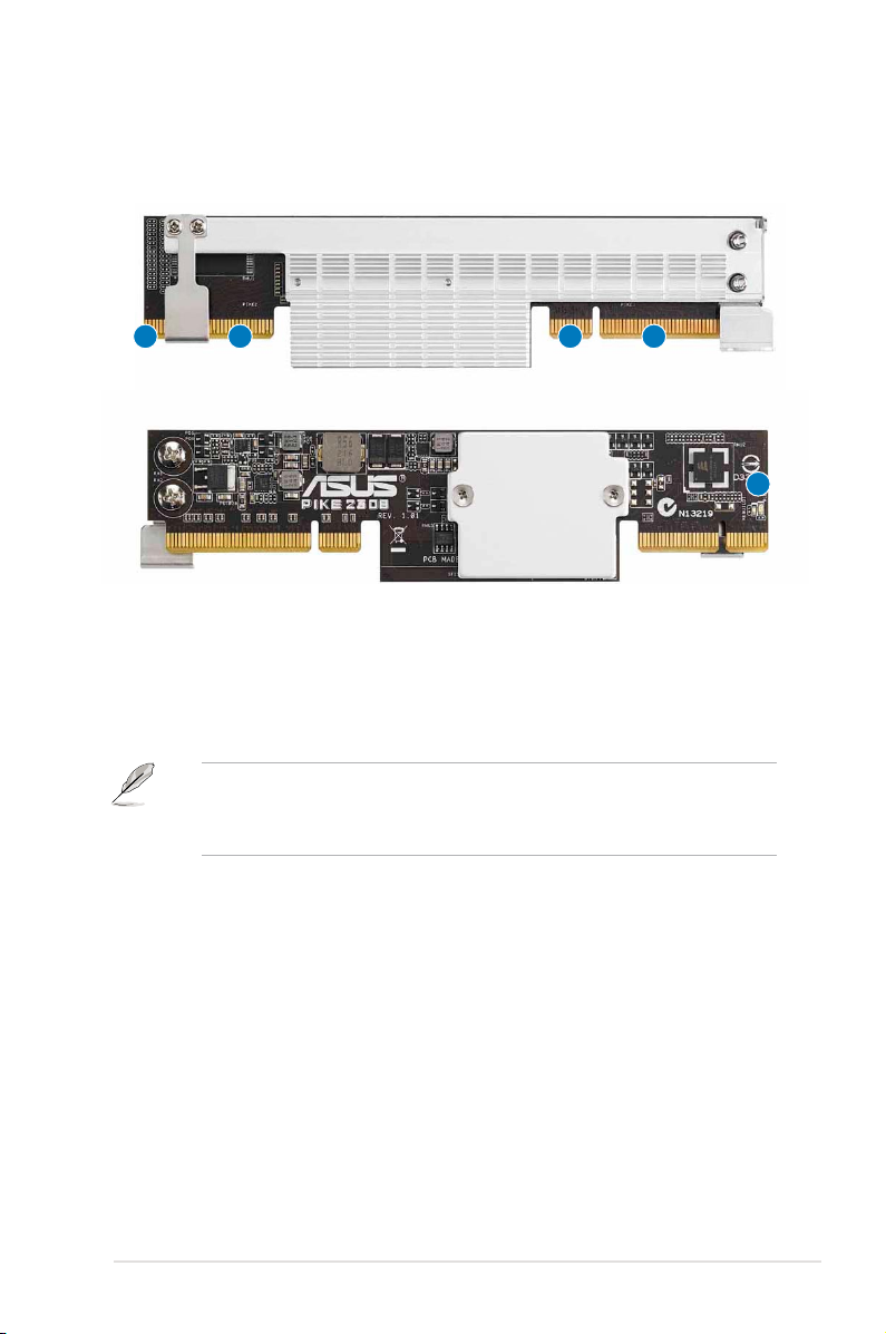
1.3 Card layout
The illustration below shows the major components of the RAID card.
2 1
12
3
1. ASUS PIKE interface-1: PCI-E x8
2. ASUS PIKE interface-2: 8-port SAS signal with SGPIO interface*
3. SAS RAID card status LED (lights up and blinks to indicate that the card is working
normally)
* The SGPIO interface is used for visibility into drive activity, failure and rebuild status,
so that users could build high-performatnce and reliable storage systems. Refer to the
motherboard manual for detailed information about using the SGPIO connectors on the
motherboard.
1.4 System requirements
Before you install the PIKE 2308 SAS RAID card, check if the system meets the following
requirements:
• Workstation or server motherboard with a PIKE RAID card slot
• SAS or SATA hard disk drives
• Supporting operating system:
Windows® and Linux operating systems (refer to website for details)
• Other requirement:
- Appropriate thermal solution
- Certied power supply module
ASUS PIKE 2308
1-3
Page 10
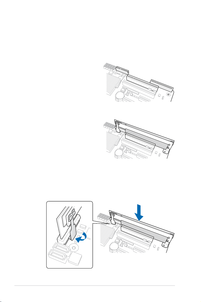
1.5 Card installation
Follow the below instructions to install the RAID card on your motherboard.
For 2U, 5U, or pedestal server
To install ASUS PIKE 2308 SAS RAID card on a 2U, 5U, or pedestal server
1. Locate the PIKE RAID card slot on the
motherboard.
2. Align the golden ngers of the RAID
card with the PIKE RAID card slot.
3. Insert the RAID card into the PIKE RAID card slot. Ensure the card is completely
inserted into the card slot, and the heatsink latch is completely hooked to the edge of
the card slot.
1-4
Chapter 1: Product introduction
Page 11
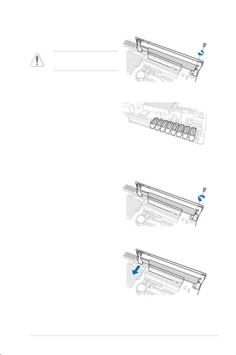
4. Secure the heatsink to the nearest
screw hole on the motherboard.
DO NOT overtighten the screw, or
the motherboard component can be
damaged.
5. Connect the hard disk drives to the SAS
connectors on the motherboard.
To uninstall ASUS PIKE 2308 SAS RAID card from a 2U, 5U, or pedestal server
1. Disconnect all SAS hard disk drives
from the motherboard.
2. Remove the screw that secures the
RAID card to the motherboard.
3. Release the heatsink latch from the
card slot with a nger, and then remove
the RAID card from the slot.
ASUS PIKE 2308
1-5
Page 12

1-6
Chapter 1: Product introduction
Page 13

This chapter provides instructions on setting up,
creating, and conguring RAID sets using the
available utilities.
Chapter 2: RAID
conguration
2
Page 14

2.1 Setting up RAID
The RAID card supports RAID 0, RAID 1, RAID 1E, and RAID 10.
2.1.1 RAID denitions
RAID 0
(Data striping)
parallel, interleaved stacks. Two hard disks perform the same work as a single drive but at a
sustained data transfer rate, double that of a single disk alone, thus improving data access
and storage. Use of at least two new identical hard disk drives is required for this setup.
RAID 1
(Data mirroring)
second drive. If one drive fails, the disk array management software directs all applications
to the surviving drive as it contains a complete copy of the data in the other drive. This RAID
conguration provides data protection and increases fault tolerance to the entire system. Use
two new drives or use an existing drive and a new drive for this setup. The new drive must be
of the same size or larger than the existing drive.
RAID 1E
alternate) copy stored on a different disk. You can use three or more hard disk drives for this
conguration.
RAID 10 is a striped conguration with RAID 1 segments whose segments are RAID 1 arrays.
This conguration has the same fault tolerance as RAID 1, and has the same overhead for
fault-tolerance as mirroring alone. RAID 10 achieves high input/output rates by striping RAID
1 segments. In some instances, a RAID 10 conguration can sustain multiple simultaneous
drive failure. A minimum of four hard disk drives is required for this setup.
(Enhanced RAID 1)
optimizes two identical hard disk drives to read and write data in
copies and maintains an identical image of data from one drive to a
has a striped layout with each stripe unit having a secondary (or
If you want to boot the system from a hard disk drive included in a created RAID set, copy
rst the RAID driver from the support CD to a oppy disk before you install an operating
system to the selected hard disk drive.
2.1.2 Installing hard disk drives
The RAID card supports SAS for RAID set conguration. For optimal performance, install
identical drives of the same model and capacity when creating a disk array.
To install the SAS hard disks for RAID conguration:
1. Install the SAS hard disks into the drive bays following the instructions in the system
user guide.
2. Connect a SAS signal cable to the signal connector at the back of each drive and to the
SAS connector on the motherboard.
3. Connect a power cable to the power connector on each drive.
2-2
Chapter 2: RAID conguration
Page 15
2.2 LSI Corporation MPT Setup Utility
The LSI Corporation MPT Setup Utility is an integrated RAID solution that allows you to
create the following RAID sets from SAS hard disk drives supported by the LSI SAS 2308
Series controller: RAID 0, RAID 1, RAID 1E, and RAID 10.
• You may use disks of different sizes in one volume; however, the size of the
smallest disk determines the “logical” size of each member disk.
• DO NOT combine Serial ATA and SAS disk drives in one volume.
• The RAID setup screens shown in this section are for reference only andThe RAID setup screens shown in this section are for reference only and
may not exactly match the items on your screen due to the controller
version difference.
• The adapter name shown on the setup screens differs according to theThe adapter name shown on the setup screens differs according to the
installed SAS RAID card.
• Before requesting support from the ASUS Technical Support team, youBefore requesting support from the ASUS Technical Support team, you
have to take note of the MPTFW and MPTBIOS version for the SAS RAID
card. After entering the SAS conguration utility, you can see below screen
and identify the MPTFW and MPTBIOS version:
MPTFW version: 5.00.00.00-IR
MPTBIOS version: v7.05.01.00 (2010.02.09)
LSI Corp Cong Utility v7.05.01.00 (2010.02.09)
Adapter List Global Properties
Adapter PCI PCI PCI PCI FW Revision Status Boot
BUS Dev Fnc Slot Order
Asus SAS2308 04 00 00 07 5.00.00.00-IR Enabled 0
Esc = Exit Menu F1/Shift+1 = Help
Alt+N = Global Properties -/+ = Alter Boot Order Ins/Del = Alter Boot List
ASUS PIKE 2308
2-3
Page 16
2.2.1 RAID 1 volume
The RAID 1 feature supports simultaneous mirrored volumes with two disks.
The RAID 1 feature supports hot swap capability, so when a disk in an RAID 1 volume fails,
you can easily restore the volume, and the swapped disk is automatically re-mirrored.
To create a RAID 1 volume:
1. Turn on the system after installing all SAS hard disk drives.
2. During POST, press <Ctrl+C> to enter the SAS conguration utility.
LSI Corporation MPT SAS2 BIOS
MPT2BIOS-7.05.01.00 (2010.02.09)
Copyright 2000-2010 LSI Corporation.
Press Ctrl-C to start LSI Corp Conguration Utility...
To avoid data loss, do not turn off the system when rebuilding.
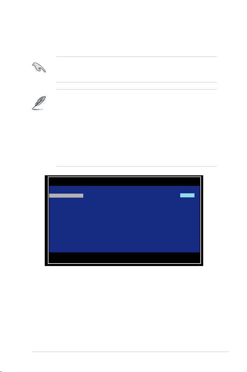
3. The following screen appears. Select a channel and press <Enter> to enter the setup.
LSI Corp Cong Utility v7.05.01.00 (2010.02.09)
Adapter List Global Properties
Adapter PCI PCI PCI PCI FW Revision Status Boot
BUS Dev Fnc Slot Order
Asus SAS2308 04 00 00 07 5.00.00.00-IR Enabled 0
2-4
Esc = Exit Menu F1/Shift+1 = Help
Alt+N = Global Properties -/+ = Alter Boot Order Ins/Del = Alter Boot List
The numbers of the channel depend on the controller.
Chapter 2: RAID conguration
Page 17
4. The Adapter Properties screen appears.
Use the arrow keys to select RAID Properties, then press <Enter>.
LSI Corp Cong Utility v7.05.01.00 (2010.02.09)
Adapter Properties -- SAS2308
Adapter Asus SAS2308
PCI Slot 07
PCI Address(Bus/Dev) 04:00
MPT Firmware Revision 5.00.00.00-IR
SAS Address 500E0180:1280E000
NVDATA Version 05.02
Status Enabled
Boot Order 0
Boot Support [Enabled BIOS & OS]
RAID Properties
SAS Topology
Advanced Adapter Properties
Esc = Exit Menu F1/Shift+1 = Help
Enter = Select Item -/+/Enter = Change Item
5. The Select New Volume Type screen appears.
Use the arrow keys to select Create RAID 1 Volume, then press <Enter>.
LSI Corp Cong Utility v7.05.01.00 (2010.02.09)
Select New Volume Type -- SAS2308
Create RAID 1 Volume Create a RAID 1 volume
Create RAID 1E/10 Volume Create a RAID 1E or RAID 10 volume
Create RAID 0 Volume Create a RAID 0 volume consisting of
consisting of 2 disks plus up to 2
optional hot spares. ALL DATA on
volume disks will be DELETED!
consisting of 3 to 10 disks including up
to 2 optional hot spares. ALL DATA on
volume disks will be DELETED!
2 to 10 disks. ALL DATA on
volume disks will be DELETED!
Esc = Exit Menu F1/Shift+1 = Help
Enter = Choose volume type to create
ASUS PIKE 2308
2-5
Page 18
6. The Create New Volume screen shows the disks you can add to make up the RAID
1 volume. Use the arrow key to select a disk, then move the cursor to the RAID Disk
column. To include this disk in the array, press <+>, <->, or <Space>.
LSI Corp Cong Utility v7.05.01.00 (2010.02.09)
Create New Volume -- SAS2308
Volume Type: RAID 1
Volume Size(GB): -------
Slot Device Identier RAID Drive Pred Size
Num Disk Status Fail (GB)
0 ATA WDC WD800JD-22LS1D06 [No] ---------- No 74
1 ATA WDC WD800JD-22LS1D06 [No] ---------- No 74
2 ATA WDC WD800JD-22LS1D06 [No] ---------- No 74
3 ATA WDC WD800JD-22LS1D06 [No] ---------- No 74
Esc = Exit Menu F1/Shift+1 = Help
SPACE/+/- = Select disk for volume C = Create volume
By default, the RAID Disk eld shows No before volume creation. This eld is grayed out
under the following conditions:
• The disk does not meet the minimum requirements for use in a RAID volume.
• The disk is not large enough to mirror existing data on the primary drive.
• The disk is already part of another volume.
2-6
Chapter 2: RAID conguration
Page 19

7. A warning screen appears. Press any key to continue.
Press <M> to keep existing data on the rst disk. If you choose this option, data on
the rst disk will be mirrored on the second disk that you will add to the volume later.
Ensure the data you want to mirror is on the rst disk.
Press <D> to overwrite any data and create the new IM array.
LSI Corp Cong Utility v7.05.01.00 (2010.02.09)
Create New Volume -- SAS2308
WARNING! Data was found on the selected disk, this data will be lost
when the volume is created!
Choose Discard conguration or Cancel Exit on the next screen to abort.
Esc = Exit Menu F1/Shift+1 = Help
SPACE/+/- = Select disk for volume C = Create array
8. Repeat step 6 to add the second disk to the volume.
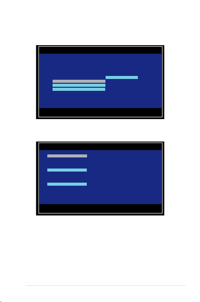
9. When done, press <C> to create the volume, then select Save changes then exit this
menu.
Create and save new volume?
Cancel Exit
Save changes then exit this menu
Discard changes then exit this menu
Exit the Conguration Utility and Reboot
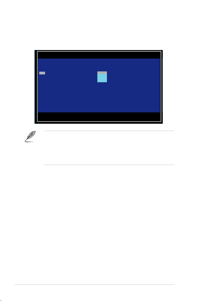
10. The utility creates the volume.
LSI Corp Cong Utility v7.05.01.00 (2010.02.09)
Create New Volume -- SAS2308
Processing...may take up to 1 minute
Creating RAID Volume...
ASUS PIKE 2308
2-7
Page 20

2.2.2 RAID 1E/10 volume
The RAID 1E/10 supports three to ten disks, or seven mirrored disks plus two hot spare
disks.
Use odd numbers of hard disk drives to create a RAID 1E volume; use even numbers of
hard disk drives to create a RAID 10 volume.
To create a RAID 1E/10 volume:
1. Follow steps 1–4 of the section RAID 1E/10 volume.
2. The Select New Volume Type screen appears.
Use the arrow keys to select Create RAID 1E/10 Volume, then press <Enter>.
LSI Corp Cong Utility v7.05.01.00 (2010.02.09)
Select New Volume Type -- SAS2308
Create RAID 1 Volume Create a RAID 1 volume
Create RAID 1E/10 Volume Create a RAID 1E or RAID 10 volume
Create RAID 0 Volume Create a RAID 0 volume consisting of
Esc = Exit Menu F1/Shift+1 = Help
Enter = Choose volume type to create
consisting of 2 disks plus up to 2
optional hot spares. ALL DATA on
volume disks will be DELETED!
consisting of 3 to 10 disks including up
to 2 optional hot spares. ALL DATA on
volume disks will be DELETED!
2 to 10 disks. ALL DATA on
volume disks will be DELETED!
3. The Create New Volume screen shows the disks you can add to make up the RAID
1E/10 volume.
RAID 1E/10 supports three to ten disks, or seven mirrored disks plus two hot spare
disks. Use the arrow key to select a disk, then move the cursor to the RAID Disk
column. To include this disk in the array, press <+>, <->, or <Space>.
2-8
Chapter 2: RAID conguration
Page 21

LSI Corp Cong Utility v7.05.01.00 (2010.02.09)
Create New Volume -- SAS2308
Volume Type: RAID 1E
Volume Size(GB): -------
Slot Device Identier RAID Drive Pred Size
Num Disk Status Fail (GB)
0 ATA WDC WD800JD-22LS1D06 [No] ---------- No 74
1 ATA WDC WD800JD-22LS1D06 [No] ---------- No 74
2 ATA WDC WD800JD-22LS1D06 [No] ---------- No 74
3 ATA WDC WD800JD-22LS1D06 [No] ---------- No 74
Esc = Exit Menu F1/Shift+1 = Help
SPACE/+/- = Select disk for volume C = Create volume
By default, the RAID Disk eld shows No before volume creation. This eld is grayed out
under the following conditions:
• The disk does not meet the minimum requirements for use in a RAID
volume.
• The disk is not large enough to mirror existing data on the primary drive.
• The disk is already part of another volume.
4. Repeat step 3 to add the other disks to the volume.
5. When done, press <C> to create the volume, then select Save changes then exit this
menu.
Create and save new volume?
Cancel Exit
Save changes then exit this menu
Discard changes then exit this menu
Exit the Conguration Utility and Reboot
6. The utility creates the volume.
LSI Corp Cong Utility v7.05.01.00 (2010.02.09)
Create New Volume -- SAS2308
Processing...may take up to 1 minute
Creating RAID Volume...
ASUS PIKE 2308
2-9
Page 22

2.2.3 RAID 0 volume
The RAID 0 feature supports volumes with two to ten disks. You may combine an RAID 0
volume with an RAID 1 or RAID 1E/10 volume.
To create a RAID 0 volume:
1. Follow steps 1–4 of the section RAID 1 volume.
2. The Select New Volume Type screen appears.
Use the arrow keys to select Create RAID 0 Volume, then press <Enter>.
LSI Corp Cong Utility v7.05.01.00 (2010.02.09)
Select New Volume Type -- SAS2308
Create RAID 1 Volume Create a RAID 1 volume
Create RAID 1E/10 Volume Create a RAID 1E or RAID 10 volume
Create RAID 0 Volume Create a RAID 0 volume consisting of
Esc = Exit Menu F1/Shift+1 = Help
Enter = Choose volume type to create
3. The Create New Volume screen shows the disks you can add to make up the RAID
0 volume. Use the arrow key to select a disk, then move the cursor to the RAID Disk
column. To include this disk in the array, press <+>, <->, or <Space>.
consisting of 2 disks plus up to 2
optional hot spares. ALL DATA on
volume disks will be DELETED!
consisting of 3 to 10 disks including up
to 2 optional hot spares. ALL DATA on
volume disks will be DELETED!
2 to 10 disks. ALL DATA on
volume disks will be DELETED!
2-10
LSI Corp Cong Utility v7.05.01.00 (2010.02.09)
Create New Volume -- SAS2308
Volume Type: RAID 0
Volume Size(GB): -------
Slot Device Identier RAID Drive Pred Size
Num Disk Status Fail (GB)
0 ATA WDC WD800JD-22LS1D06 [No] ---------- No 74
1 ATA WDC WD800JD-22LS1D06 [No] ---------- No 74
2 ATA WDC WD800JD-22LS1D06 [No] ---------- No 74
3 ATA WDC WD800JD-22LS1D06 [No] ---------- No 74
Esc = Exit Menu F1/Shift+1 = Help
SPACE/+/- = Select disk for volume C = Create volume
Chapter 2: RAID conguration
Page 23

By default, the RAID Disk eld shows No before volume creation. This eld is grayed out
under the following conditions:
• The disk does not meet the minimum requirements for use in a RAID
volume.
• The disk is not large enough to mirror existing data on the primary drive.
• The disk is already part of another volume.
4. Repeat step 3 to add the other disks to the volume.
5. When done, press <C> to create the volume, then select Save changes then exit this
menu.
Create and save new volume?
Cancel Exit
Save changes then exit this menu
Discard changes then exit this menu
Exit the Conguration Utility and Reboot
6. The utility creates the volume.
LSI Corp Cong Utility v7.05.01.00 (2010.02.09)
Create New Volume -- SAS2308
Processing...may take up to 1 minute
Creating RAID Volume...
ASUS PIKE 2308
2-11
Page 24

2.2.4 Managing Arrays
The LSI Corporation MPT Setup Utility allows you to perform other tasks related to
conguring and maintaining RAID volumes.
Refer to this section to view volume properties, manage the hot spare disk, proceed with the
volume consistency check, activate the volume, delete the volume, and expand the volume
capacity.
Viewing volume properties
To view volume properties:
1. On the main menu, select RAID Properties.
LSI Corp Cong Utility v7.05.01.00 (2010.02.09)
Adapter Properties -- SAS2308
Adapter PIKE 2308
PCI Slot 07
PCI Address(Bus/Dev) 04:00
MPT Firmware Revision 5.00.00.00-IR
SAS Address 500E0180:1280E000
NVDATA Version 05.02
Status Enabled
Boot Order 0
Boot Support [Enabled BIOS & OS]
RAID Properties
SAS Topology
Advanced Adapter Properties
Esc = Exit Menu F1/Shift+1 = Help
Enter = Select Item -/+/Enter = Change Item
2. On the next screen that appears, select View Existing Volume.
LSI Corp Cong Utility v7.05.01.00 (2010.02.09)
Select New Volume Type -- SAS2308
View Existing Volume View the existing conguration.
2-12
Create RAID 1 Volume Create a RAID 1 volume
Create RAID 1E/10 Volume Create a RAID 1E or RAID 10 volume
Create RAID 0 Volume Create a RAID 0 volume consisting of
Esc = Exit Menu F1/Shift+1 = Help
Enter = Choose volume type to create
consisting of 2 disks plus up to 2
optional hot spares. ALL DATA on
volume disks will be DELETED!
consisting of 3 to 10 disks including up
to 2 optional hot spares. ALL DATA on
volume disks will be DELETED!
2 to 10 disks. ALL DATA on
volume disks will be DELETED!
Chapter 2: RAID conguration
Page 25

3. The View Volume screen appears. Here you can view properties of the RAID
volume(s) created. If you have congured a hot spare, it will also be listed. If you
created more than one volume, you may view the next volume by pressing <Alt+N>.
LSI Corp Cong Utility v7.05.01.00 (2010.02.09)
View Volume -- SAS2308
Volume 1 of 1
Identier LSI Logical Volume 3000
Type RAID 1
Size(GB) 73
Status Optimal
Task None
Manage Volume
Slot Device Identier RAID Hot Drive Pred Size
Num Disk Spr Status Fail (GB)
0 ATA WDC WD800JD-22LS1D06 Yes No Primary No 73
1 ATA WDC WD800JD-22LS1D06 Yes No Secondary No 73
Esc = Exit Menu F1/Shift+1 = Help
Enter=Select Item Alt+N=Next Volume
ASUS PIKE 2308
2-13
Page 26

Managing hot spares
You may congure one disk as a global hot spare to protect critical data on the
RAID 1/1E/10 volume(s). You may create the hot spare disk at the same time you
create the RAID 1/1E/10 volume. Refer to this section when adding a hot spare
disk on an existing volume.
If a disk on an RAID 1/1E/10 volume fails, the utility automatically rebuilds the
failed disk data on the hot spare. When the failed disk is replaced, the utility
assigns the replacement as the new hot spare.
To create a hot spare:
1. Follow steps 1–3 of the section Viewing volume properties.
2. From the View Volume screen, select Manage Volume, then press <Enter>.
LSI Corp Cong Utility v7.05.01.00 (2010.02.09)
View Volume -- SAS2308
Volume 1 of 1
Identier LSI Logical Volume 3000
Type RAID 1
Size(GB) 73
Status Optimal
Task None
Manage Volume
Slot Device Identier RAID Hot Drive Pred Size
Num Disk Spr Status Fail (GB)
0 ATA WDC WD800JD-22LS1D06 Yes No Primary No 73
1 ATA WDC WD800JD-22LS1D06 Yes No Secondary No 73
Esc = Exit Menu F1/Shift+1 = Help
Enter=Select Item Alt+N=Next Volume
3. From the Manage Volume screen, select Manage Hot Spares, then press
<Enter>.
LSI Corp Cong Utility v7.05.01.00 (2010.02.09)
Manage Volume -- SAS2308
Identier LSI Logical Volume 3000
Type RAID 1
Size(GB) 73
Status Optimal
Task None
Manage Hot Spares
Consistency Check
Activate Volume
Delete Volume
Online Capacity Expansion
Esc = Exit Menu F1/Shift+1 = Help
Enter = Select Item
2-14
Chapter 2: RAID conguration
Page 27

4. Use the arrow key to select the disk you would like to congure as hot spare, then
move the cursor to the Hot Spr column. Press <+>, <->, or <Space>.
Press <C> to commit the changes. The Drive Status column eld now shows Hot
Spare.
LSI Corp Cong Utility v7.05.01.00 (2010.02.09)
Manage Hot Spare -- SAS2308
Identier LSI Logical Volume 3000
Type RAID 1
Size(GB) 73
Status Optimal
Task None
Slot Device Identier Hot Drive Pred Size
Num Spr Status Fail (GB)
0 ATA WDC WD800JD-22LS1D06 [No] RAID No 74
1 ATA WDC WD800JD-22LS1D06 [No] RAID No 74
2 ATA WDC WD800JD-22LS1D06 [No] ---------- No 74
3 ATA WDC WD800JD-22LS1D06 [No] ---------- No 74
Esc = Exit Menu F1/Shift+1 = Help
SPACE/+/- = Change Item C = Commit Changes
Running a consistency check
To run a consistency check on the RAID volume:
1. Follow steps 1–3 of the section Viewing volume properties and step 2 of the section
Managing hot spares.
2. From the Manage Volume screen select Consistency Check, then press <Enter>.
3. The below screen appears. Press <Enter> to start the consistency check on the RAID
volume.
LSI Corp Cong Utility v7.05.01.00 (2010.02.09)
Manage Volume -- SAS2308
Press Enter to run a consistency check on the RAID volume.
This eld is grayed out under the following conditions:
- The adapter’s MPT FW does not support the feature
- The volume is a RAID 0
- The volume is not optimal
- The volume is already running a consistency check
- The volume has a consistency check pending
Esc = Exit Menu F1/Shift+1 = Help
Enter = Select Item
ASUS PIKE 2308
2-15
Page 28

Activating a volume
If a volume is removed from one controller/computer or moved to another, the volume is
considered inactive. When you add the volume back to the system, you may reactivate the
volume.
To activate the volume:
1. From the Manage Volume screen, select Activate Volume, then press <Enter>.
LSI Corp Cong Utility v7.05.01.00 (2010.02.09)
Manage Volume -- SAS2308
Identier LSI Logical Volume 3000
Type RAID 1
Size(GB) 73
Status Optimal
Task None
Manage Hot Spares
Consistency Check
Activate Volume
Delete Volume
Online Capacity Expansion
Esc = Exit Menu F1/Shift+1 = Help
Enter = Select Item
2. The below screen appears. Press <Enter> to activate a RAID volume.
LSI Corp Cong Utility v7.05.01.00 (2010.02.09)
Manage Volume -- SAS2308
This eld is used to activate a RAID volume.
This eld is grayed out under the following conditions:
- The volume is currently active.
- Activating the volume would exceed the maximum number of
active volumes allowsed.
- Activating the volume would exceed the maximum number of
RAID disks allowed.
- The volume has incompatible metadata on it.
2-16
Esc = Exit Menu F1/Shift+1 = Help
Enter = Select Item
Chapter 2: RAID conguration
Page 29

Deleting a volume
• You cannot recover lost data if you delete a volume. Ensure you back up
important data before deleting a volume.
• If you delete a RAID 1 volume, the data is preserved on the primary disk.
To delete a volume:
1. From the Manage Volume screen, select Delete Volume, then press <Enter>.
LSI Corp Cong Utility v7.05.01.00 (2010.02.09)
Manage Volume -- SAS2308
Identier LSI Logical Volume 3000
Type RAID 1
Size(GB) 73
Status Optimal
Task None
Manage Hot Spares
Consistency Check
Activate Volume
Delete Volume
Online Capacity Expansion
Esc = Exit Menu F1/Shift+1 = Help
Enter = Select Item
2. The below screen appears. Press <Y> to delete, or <N> to cancel.
LSI Corp Cong Utility v7.05.01.00 (2010.02.09)
Manage Volume -- SAS2308
WARNING! All data will be lost when the volume is deleted!
Y Delete volume and exit to Adapter Properties
N Abandon volume deletion and exit this menu
Esc = Exit Menu F1/Shift+1 = Help
Enter = Select Item
ASUS PIKE 2308
2-17
Page 30

Expanding the volume capacity
You may use two new hard disk drives to replace the existing one, and expand the capacity
of the RAID volume.
• The capactiy of th new hard disk drives should be 50GB larger than the existing one.
• This function is available only when the RAID 1 volume is optimal.This function is available only when the RAID 1 volume is optimal.
To expand the capacity of the currently displayed RAID volume:
1. From the Manage Volume screen, select Online Capacity Expansion, then press
<Enter>.
LSI Corp Cong Utility v7.05.01.00 (2010.02.09)
Manage Volume -- SAS2308
Identier LSI Logical Volume 3000
Type RAID 1
Size(GB) 73
Status Optimal
Task None
Manage Hot Spares
Consistency Check
Activate Volume
Delete Volume
Online Capacity Expansion
Esc = Exit Menu F1/Shift+1 = Help
Enter = Select Item
2. The below screen appears. Press <Enter> to proceed with the capacity expansion.
LSI Corp Cong Utility v7.05.01.00 (2010.02.09)
Manage Volume -- SAS2308
This eld is used to expand the capacity of the currently displayed
RAID volume.
This eld is disabled under the following conditions:
- The volume is not a RAID 1 volume.
- Firmware is congured to diable this feature.
Esc = Exit Menu F1/Shift+1 = Help
Enter = Select Item
2-18
Chapter 2: RAID conguration
Page 31

2.2.5 Viewing SAS topologyViewing SAS topology
1. From the Adapter Properties screen, select SAS Topology, then press <Enter>.
LSI Corp Cong Utility v7.05.01.00 (2010.02.09)
Adapter Properties -- SAS2308
Adapter PIKE 2308
PCI Slot 07
PCI Address(Bus/Dev) 04:00
MPT Firmware Revision 5.00.00.00-IR
SAS Address 500E0180:1280E000
NVDATA Version 05.02
Status Enabled
Boot Order 0
Boot Support [Enabled BIOS & OS]
RAID Properties
SAS Topology
Advanced Adapter Properties
Esc = Exit Menu F1/Shift+1 = Help
Enter = Select Item -/+/Enter = Change Item
2. Information about the volume and its member-disks are then displayed.
LSI Corp Cong Utility v7.05.01.00 (2010.02.09)
SAS Topology -- SAS2308
Device Identier Device
PIKE 2308(04:00) Info
﹂ Controller Direct Attach Devices Controller
﹂ RAID1 VOL LSI Logical Volume 3000
Esc = Exit F1/Shift+1 = Help
Alt+D = Device Properties Alt+M = More Keys
You may press <Alt+D> to display device properties, or <Alt+M> to display more keys.
LSI Corp Cong Utility v7.05.01.00 (2010.02.09)
SAS Topology -- SAS2308
More keys for the SAS Topology display:
Alt+B = Select or deselect a device as the preferred boot device
Alt+A = Select or deselect a device as the alternate boot device
Enter = On a SAS Enclosure or Expander - Expand or Collapse Item
Enter = On a Disk Drive - Turn on the Locate LED (next key press turns off)
ASUS PIKE 2308
2-19
Page 32

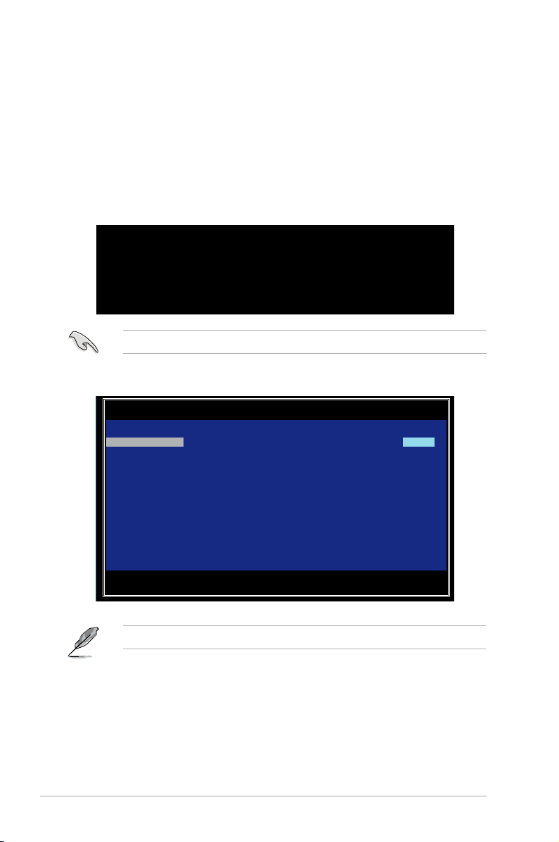
2.2.6 Global Properties
From the Adapter List screen, press <Alt+N> to enter Global Properties menu. From the
menu you may change related settings.
LSI Corp Cong Utility v7.05.01.00 (2010.02.09)
Adapter List Global Properties
Adapter PCI PCI PCI PCI FW Revision Status Boot
BUS Dev Fnc Slot Order
PIKE 2308 04 00 00 07 5.00.00.00-IR Enabled 0
Esc = Exit Menu F1/Shift+1 = Help
Alt+N = Global Properties -/+ = Alter Boot Order Ins/Del = Alter Boot List
Pause When Boot Alert Displayed
Sets whether to pause or not when the boot alert displays.
Conguration options: [Yes] [No]
LSI Corp Cong Utility v7.05.01.00 (2010.02.09)
Adapter List Global Properties
2-20
Pause When Boot Alert Displayed [No]
Boot Information Display Mode [Display minimal information]
Support Interrupt [Hook interrupt, the Default]
Restore Defaults
Esc = Exit Menu F1/Shift+1 = Help
Alt+N = Adapter List -/+ = Change Item
Chapter 2: RAID conguration
Page 33

Boot Information Display Mode
Sets the disk information display mode.
Conguration options: [Display adapters & installed devices]
[Display adapters only] [Display adapters and all devices]
[Display minimal information]
LSI Corp Cong Utility v7.05.01.00 (2010.02.09)
Adapter List Global Properties
Pause When Boot Alert Displayed [No]
Boot Information Display Mode [Display minimal information]
Support Interrupt [Hook interrupt, the Default]
Restore Defaults
Esc = Exit Menu F1/Shift+1 = Help
Alt+N = Adapter List -/+ = Change Item
Support Interrupt
Conguration options: [Hook interrupt, the Default] [Bypass interrupt hook]
LSI Corp Cong Utility v7.05.01.00 (2010.02.09)
Adapter List Global Properties
Pause When Boot Alert Displayed [No]
Boot Information Display Mode [Display minimal information]
Support Interrupt [Hook interrupt, the Default]
Restore Defaults
Esc = Exit Menu F1/Shift+1 = Help
Alt+N = Adapter List -/+ = Change Item
ASUS PIKE 2308
2-21
Page 34

Restore Defaults
This option allows you to discard the selections you made and restore the system defaults.
LSI Corp Cong Utility v7.05.01.00 (2010.02.09)
Adapter List Global Properties
Pause When Boot Alert Displayed [No]
Boot Information Display Mode [Display minimal information]
Support Interrupt [Hook interrupt, the Default]
Restore Defaults
Esc = Exit Menu F1/Shift+1 = Help
Alt+N = Adapter List -/+ = Change Item
2-22
Chapter 2: RAID conguration
Page 35

2.3 MegaRAID Storage Manager
MegaRAID Storage Manager software enables you to congure, monitor, and maintain
storage congurations on LSI SAS controllers. The MegaRAID Storage Manager graphical
user interface (GUI) makes it easy for you to create and manage storage congurations.
2.3.1 Hardware and Software Requirements
The hardware requirements for MegaRAID Storage Manager software are as follows:
PC-compatible computer with an IA-32 (32-bit) Intel Architecture processor or an
•
EM64T (64-bit) processor and at least 128 Mbytes of system memory (256 Mbytes
recommended)
Disk drive with at least 50 Mbytes available free space
•
Refer to your server documentation and to the operating system documentation for more
information on hardware and operating system requirements.
2.3.2 Installing MegaRAID Storage Manager Sofware on
Microsoft Windows OS
Follow these steps if you need to install MegaRAID Storage Manager software on a system
running Microsoft Windows OS:
1. Insert the MegaRAID Storage Manager software installation CD in the CD-ROM drive.
If necessary, nd and double-click the setup.exe le to start the installation program.
2. When the Welcome screen appears, click Next.
If MegaRAID Storage Manager software is already installed on this system, the
Program Maintenance screen appears. Read the screen text and select Modify,
Repair, or Remove.
3. When the next screen appears, read and accept the user license, and click Next.
The Customer Information screen appears, as shown in the following gure.
ASUS PIKE 2308
2-23
Page 36

4. Enter your user name and organization name. In the bottom part of the screen, select
an installation option:
– If you select All users, any user with administrative privileges can use this
version of MegaRAID Storage Manager software to view or change storage
congurations.
– If you select Only for current user, the MegaRAID Storage Manager shortcuts
and associated icons will be available only to the user with this user name.
5. Click Next to continue.
6. On the next screen, accept the default Destination Folder, or click Change to select a
different destination folder. Click Next to continue.
The Setup Type screen appears, as shown in the following gure.
2-24
Chapter 2: RAID conguration
Page 37

7. Select one of the Setup options. The options are fully explained in the screen text.
– Normally, you would select Complete if you are installing MegaRAID Storage
Manager software on a server.
– Select Custom Installation if you want to select individual program components.
8. Click Next to continue.
If you selected Custom Installation as your setup option, the second Setup Type
screen appears, as shown in the following gure.
If you select Complete as your setup option, the Installation Wizard is ready to install
MSM. To begin installation, click on Install on the next screen that appears.
9. Select one of the custom setup options. The options are fully explained in the screen
text.
– Select Client if you are installing MegaRAID Storage Manager software on a
PC that will be used to view and congure servers over a network. To begin
installation, click on Install on the next screen that appears.
– Select Server to install only those components required for remote server
management. To begin installation, click on Install on the next screen that
appears.
– Select StandAlone if you will use MegaRAID Storage Manager software to
create and manage storage congurations on a standalone workstation. To begin
installation, click on Install on the next screen that appears.
– Select Custom if you want to specify individual program features to install.
ASUS PIKE 2308
2-25
Page 38

If you select Custom, a window listing the installation features appears, as shown in
the following gure. Select the features you want on this screen.
10. Click Next to proceed.
11. Click Install to install the program.
12. When the nal Conguration Wizard screen appears, click Finish.
If you select Client installation for a PC used to monitor servers, and if there are no
available servers with a registered framework on the local subnet (that is, servers with
a complete installation of MegaRAID Storage Manager software), the server screen will
appear, as shown in the following gure. The server screen will not list any servers. You
can use this screen to manage systems remotely.
2-26
Chapter 2: RAID conguration
Page 39

2.3.3 Installing MegaRAID Storage Manager Sofware for
Linux
Follow these steps if you need to install MegaRAID Storage Manager software on a system
running Red Hat Linux or SUSE Linux:
1. Copy the MSM_linux_installer...tar.gz le to a temporary folder.
2. Untar the MSM_linux_installer...tar.gz le using the following command:
tar -zxvf MSM_linux_installer...tar.gz
A new disk directory is created.
3. Go to the new disk directory.
4. In the disk directory, nd and read the readme.txt le.
5. To start the installation, enter the following command:
csh install.sh -a
If you select Client installation for a PC used to monitor servers, and if there are no available
servers with a registered framework on the local subnet (that is, servers with a complete
installation of MegaRAID Storage Manager software), the server screen appears. The server
screen does not list any servers. You can use this screen to manage systems remotely.
ASUS PIKE 2308
2-27
Page 40

2.3.4 Linux Error Messages
The following messages may appear while you are installing MegaRAID Storage Manager
software on a Linux system:
• More than one copy of MegaRAID Storage Manager software has been installed.
This message indicates that the user has installed more than one copy of MegaRAID
Storage Manager software. (This can be done by using the rpm-force command to
install the rpm le directly, which is not recommended, instead of using the install.sh
le.) In such cases, the user must uninstall all the rpm les manually before installing
MegaRAID Storage Manager software with the procedure listed previously.
• The version is already installed.
This message indicates that the version of MegaRAID Storage Manager software you
are trying to install is already installed on the system.
• The installed version is newer.
This message indicates that a version of MegaRAID Storage Manager software is
already installed on the system, and it is a newer version than the version you are
trying to install.
• Exiting installation.
This is the message that appears when the installation is complete.
• RPM installation failed.
This message indicates that the installation failed for some reason. Additional message
text explains the cause of the failure.
2-28
Chapter 2: RAID conguration
Page 41

2.3.5 Starting MegaRAID Storage Manager Software
Follow these steps to start MegaRAID Storage Manager software and view the main window:
1. Start the program using the method required for your operating system environment:
– To start MegaRAID Storage Manager software on a Microsoft Windows system,
select Start > Programs > MegaRAID Storage Manager > StartupUI, or doubleclick the MegaRAID Storage Manager shortcut on the desktop.
If a warning appears stating that Windows Firewall has blocked some features of the
program, click Unblock to allow MegaRAID Storage Manager software to start. (The
Windows Firewall sometimes blocks the operation of programs that use Java.)
– To start MegaRAID Storage Manager software on a Red Hat Linux system, select
Applications > System Tools > MegaRAID Storage Manager StartupUI.
– To start MegaRAID Storage Manager software on a SUSE SLES system, select
Start > System > More Programs > MegaRAID Storage Manager.
2. When the program starts, the Select Server window appears, as shown in the following
gure.
If the circle in the server icon is yellow instead of green, it means that the server is
running in a degraded state—for example, because a disk drive used in a virtual disk
has failed. If the circle is red, the storage conguration in the server has failed.
ASUS PIKE 2308
2-29
Page 42

To access servers on a different subnet, type in the box at the bottom of the screen the IP
address of a server in the desired subnet where the MegaRAID Storage Manager software
is running, and click Update. If you check the Connect to remote server at: IP address
box, you can also access a standalone (remote) installation of MegaRAID Storage Manager
software, if it has a network connection.
3. Double-click the icon of the server that you want to access. The Server Login window
appears, as shown in the following gure.
4. Select an access mode from the drop-down menu.
– Select Full Access if you need to both view the current conguration and change
the conguration.
– Select View Only if you need to only view and monitor the conguration.
5. Enter your user name and password, and click Login.
If the computer is networked, this is the login to the computer itself, not the network login.
You must enter the root/administrator user name and password to use Full Access
mode. If your user name and password are correct for the Login mode you have
chosen, the main MegaRAID Storage Manager window appears.
2-30
Chapter 2: RAID conguration
Page 43

2.3.6 MegaRAID Storage Manager Window
This section describes the MegaRAID Storage Manager window, which is shown in the
following gure.
Physical/Logical View Panel
The left panel of the MegaRAID Storage Manager window displays either the Physical view
or the Logical view of the system and the devices in it, depending on which tab is selected.
The Physical view shows the hierarchy of physical devices in the system. At the top of
•
the hierarchy is the system itself. One or more controllers are installed in the system.
The controller label identies the MegaRAID controller, such as the ASUS PIKE 2308
controller, so that you can easily differentiate between multiple controllers. Each
controller has one or more ports. Disk drives and other devices are attached to the ports.
The Logical view shows the hierarchy of controllers, virtual disks, and disk groups that
•
are dened on the system. (Physical drives also appear in the Logical view, so you can
see which physical drives are used by each virtual disk.)
The following icons in the left panel represent the controllers, disk drives, and other devices:
System
•
Controller
•
Port
•
Volume
•
Virtual disk
•
ASUS PIKE 2308
2-31
Page 44

Physical drive
•
A red circle to the right of an icon indicates that the device has failed. For example, this icon
indicates that a physical drive has failed: .
A yellow circle to the right of an icon indicates that a device is running in a degraded state.
For example, this icon indicates that a virtual disk is running in a degraded state because a
disk drive has failed: .
Properties View Panel
The right panel of the MegaRAID Storage Manager window has the Properties tab that
displays information about the selected device. For example, if a controller icon is selected in
the left panel, the Properties tab lists information such as the controller name, NVRAM size,
and device port count.
Event Log Panel
The lower part of the MegaRAID Storage Manager window displays the system event log
entries. New event log entries appear during the session. Each entry has an ID, a timestamp
and date, an error level indicating the severity of the event, and a brief description of the
event.
Menu Bar
Here are brief descriptions of the main selections on the MegaRAID Storage Manager menu
bar.
Manage Menu
The Manager menu has an Exit option for exiting from the MegaRAID Storage
Manager software. It also has a Refresh option for updating the display in the
MegaRAID Storage Manager window. (Refresh is seldom required; the display
normally updates automatically.) The Manage menu options also include Check
Consistency, Initialize, and Show Progress.
2-32
Go To Menu
The Go To menu is available when a controller, physical drive, or virtual disk is
selected in the MegaRAID Storage Manager window. The Go To menu options vary
depending on what type of device is selected in the left panel of the MegaRAID
Storage Manager window. For example, the Scan Foreign Conguration option is
available only when a controller is selected. The options also vary depending on the
current state of the selected device. For example, if you select an ofine physical drive,
the Make Drive Online option will be available in the Go To menu.
Chapter 2: RAID conguration
Page 45

Log Menu
The Log menu includes options for saving and clearing the message log.
Tools Menu
On the Tools menu you can select Congure Alerts to access the Event Conguration
Notication screen, which you can use to set the alert delivery rules, event severity
levels, exceptions, and email settings.
Help Menu
On the Help menu you can select Help > Contents to view the MegaRAID Storage
Manager online help le. You can select Help > About MegaRAID Storage Manager
to view version information for the MegaRAID Storage Manager software.
• When you use the MegaRAID Storage Manager online help, you may see a warning
message that Internet Explorer has restricted the le from showing active content. If
this warning appears, click on the active content warning bar and enable the active
content.
• If you are using the Linux operating system, you must install Firefox® or Mozilla® for
the MegaRAID Storage Manager online help to display.
ASUS PIKE 2308
2-33
Page 46

2-34
Chapter 2: RAID conguration
Page 47

This chapter provides instructions for installing the
RAID drivers on different operating systems.
Chapter 3: Driver
installation
3
Page 48

3.1 RAID driver installation
After creating the RAID sets for your server system, you are now ready to install an operating
system to the independent hard disk drive or bootable array. This part provides instructions on
how to install or update the RAID card drivers.
The RAID card driver might be included in the Linux OS installation CD, and could be
loaded automatically during OS installation. However, we recommend using the RAID driver
packaged in the RAID card support CD for better reliability.
3.1.1 Creating a RAID driver disk
You may have to use another system to create the RAID driver disk from the RAID card
support CD or from the Internet.
A oppy disk with the RAID driver is required when installing Windows
®
Server 2003 or Linux
operating system on a hard disk drive that is included in a RAID set. You can create a RAID
driver disk in DOS (using the Makedisk application in the support CD).
To create a RAID driver disk in DOS environment:
1. Place the RAID card support CD in the optical drive.
2. Restart the computer, then enter the BIOS Setup.
3. Select the optical drive as the rst boot priority to boot from the support CD. Save your
changes, then exit the BIOS Setup.
4. Restart the computer.
5. The Makedisk menu appears. SelectThe Makedisk menu appears. Select PIKE 2308 SASs card Driver, and press <Enter>
to enter the sub-menu.
Create Driver Diskette Menu
PIKE 2308 SAS2 card Driver
FreeDOS command prompt
3-2
Chapter 3: Driver installation
Page 49

6. Use the arrow keys to select the type of RAID driver disk you want to create.
PIKE 2308 SAS2 card Driver
Windows XP x86
Windows XP x64
Windows Server 2003 x86
Windows Server 2003 x64
Windows Vista x86
Windows Vista x64
Windows Server 2008 x86
Windows Server 2008 x64
Windows 7 x86
Windows 7 x64
Windows Server 2008 R2 x64
RHEL 4 UP6 i686
RHEL 4 UP6 x86_64
RHEL 4 UP7 i686
RHEL 4 UP7 x86_64
RHEL 4 UP8 i686
RHEL 4 UP8 x86_64
RHEL 5 i686
RHEL 5 x86_64
RHEL 5 UP1 i686
RHEL 5 UP1 x86_64
RHEL 5 UP2 i686
7. Place a blank, high-density oppy disk to the oppy disk drive.
8. Press <Enter>.
9. Follow screen instructions to create the driver disk.
ASUS PIKE 2308
3-3
Page 50

3.1.2 Windows® Server 2003 OS
During Windows® Server 2003 OS installation
To install the RAID card driver when installing Windows® Server 2003 OS:
1. Boot the computer using the Windows® Server 2003 OS installation CD. The Window®
Setup starts.
2. Press <F6> when the message “Press F6 if you need to install a third party SCSI or
RAID driver...” appears at the bottom of the screen.
Windows Setup
Press F6 if you need to install a third party SCSI or RAID driver...
3. The next screen appears. Press <S> to specify an additional device.
3-4
Windows Setup
Setup could not determine the type of one or more mass storage devices
installed in your system, or you have chosen to manually specify an adapter.
Currently, Setup will load support for the following mass storage devices(s):
<none>
* To specify additional SCSI adapters, CD-ROM drives, or special
disk controllers for use with Windows, including those for
which you have a device support disk from a mass storage device
manufacturer, press S.
* If you do not have any device support disks from a mass storage
device manufacturer, or do not want to specify additional
mass storage devices for use with Windows, press ENTER.
S=Specify Additional Device ENTER=Continue F3=Exit
Chapter 3: Driver installation
Page 51

4. Insert the RAID driver disk you created earlier to the oppy disk drive, then press
<Enter>.
Windows Setup
Please insert the disk labeled
Manufacturer-supplied hardware support disk
into Drive A:
* Press ENTER when ready.
ENTER=Continue ESC=Cancel F3=Exit
5. Select LSI Fusion-MPT SAS Driver (Server 2003 32-bit), then press <Enter>.
Windows Setup
You have chosen to congure a SCSI Adapter for use with Windows,
using a device support disk provided by an adapter manufacturer.
Select the SCSI Adapter you want from the following list, or press ESC
to return to the previous screen.
LSI Fusion-MPT SAS Driver (Server 2003 32-bit)
ENTER=Select F3=Exit
6. The Windows® Setup loads the RAID card drivers from the RAID driver disk. When
next screen appears, press <Enter> to continue installation.
7. Setup then proceeds with the OS installation. Follow screen instructions to continue.
ASUS PIKE 2308
3-5
Page 52

After Windows® Server 2003 OS installation
To update the RAID card driver after installing Windows® Server 2003 OS:
1. Right-click the My Computer icon on the desktop and select Properties from the
menu.
2. Click the Hardware tab on the top, then click the Device Manager button.
3. Double-click the LSI Adapter, SAS2 2308 Falcon -StorPort item.
The controller name differs according to the installed SAS RAID card.
LSI Adapter, SAS2 2308 Falcon -StorPort
4. Click the Driver tab on the top, then click Update Driver.
LSI Adapter, SAS2 2008 Falcon -StorPort
3-6
Chapter 3: Driver installation
Page 53

5. Toggle Install from a list or specic location (Advanced), then click Next to
continue.
LSI Adapter, SAS2 2308 Falcon -StorPort
6. Toggle Don’t search. I will choose the driver to install, then click Next to continue.
7. Insert the RAID driver disk you created earlier to the oppy disk drive.
8. Highlight LSI Adapter, SAS2 2308 Falcon -StorPort, then click Have Disk.
LSI Adapter, SAS2 2308 Falcon -StorPort
ASUS PIKE 2308
3-7
Page 54

9. Select from the drop-down menu and locate the driver.
10. Click Next to start updating the driver.
LSI Adapter, SAS2 2308 Falcon -StorPort
11. After completing driver update, click Finish to close the wizard.
3-8
LSI Adapter, SAS2 2308 Falcon -StorPort
Chapter 3: Driver installation
Page 55

3.1.3 Red Hat® Enterprise Linux OS 5
To install the RAID card driver when installing Red Hat Red Hat® Enterprise OS:
1. Boot the system from the Red Hat® OS installation CD.
2. At the boot:, type linux dd, then press <Enter>.
- To install or upgrade in graphical mode, press the <ENTER> key.
- To install or upgrade in text mode, type: linux text <ENTER>.
- Use the function keys listed below for more information.
[F1-Main] [F2-Options] [F3-General] [F4-Kernel] [F5-Rescue]
boot: linux dd
3. Select Yes using the <Tab> key when asked if you have the driver disk, then press
<Enter>.
Main Menu
Do you have a driver disk?
Yes No
4. Insert the Red Hat® Enterprise RAID driver disk to the oppy disk drive, select OK, then
press <Enter>.
Insert Driver Disk
Insert your driver disk into /dev/sda and
press “OK” to continue.
OK
Back
The drivers for the RAID card are installed to the system.
ASUS PIKE 2308
3-9
Page 56

5. When asked if you will load additional RAID controller drivers, select No, then press
<Enter>.
More Driver Disks?
Do you wish to load any more
driver disks?
Yes No
6. Follow the screen instructions to continue the OS installation.
3-10
Chapter 3: Driver installation
Page 57

3.1.4 SUSE Linux OS 11
To install the RAID card driver when installing SUSE Linux Enterprise Server OS: SUSE Linux Enterprise Server OS:
1. Boot the system from the SUSE OS installation CD.
2. Use the arrow keys to select Installation from the Boot Options menu.
3. Press <F6>, then select Yes from the menu. Press <Enter>.
4. Insert the RAID driver disk to the oppy disk drive. Enure that Installation from the Boot
Options menu is selected, then press <Enter>.
5. When below screen appears, select the oppy disk drive (fd0) as the driver update
medium. Select OK, then press <Enter>.
Please choose the Driver Update medium.
sda: USB Floppy
sr0: CD-ROM, ASUS DRW-2014S1T
Other device
OK Back
The drivers for the RAID controller are installed to the system.
ASUS PIKE 2308
3-11
Page 58

ASUS contact information
ASUSTeK COMPUTER INC.
Address 15 Li-Te Road, Peitou, Taipei, Taiwan 11259
Telephone +886-2-2894-3447
Fax +886-2-2890-7798
E-mail info@asus.com.tw
Web site http://www.asus.com.tw
Technical Support
Telephone +86-21-38429911
Fax +86-21-58668722 ext: 9101
Online Support http://support.asus.com/techserv/techserv.aspx
ASUSTeK COMPUTER INC. (Taiwan)
Address 15 Li-Te Road, Peitou, Taipei, Taiwan 11259
Telephone +886-2-2894-3447
Fax +886-2-2890-7798
E-mail info@asus.com.tw
Web site http://www.asus.com.tw
Technical Support
Telephone +886-2-2894-3447 (0800-093-456)
Online Support http://support.asus.com/techserv/techserv.aspx
ASUSTeK COMPUTER INC. (China)
Address No.508, Chundong Road , Xinzhuang Industr ial Zone,
Minhang District, Shanghai, China.
Telephone +86-21-5442-1616
Fax +86-21-5442-0099
Web site http://www.asus.com.cn
Technical Support
Telephone +86-21-3407-4610 (800-820-6655)
Online Support http://support.asus.com/techserv/techserv.aspx
3-12
Chapter 3: Driver installation
Page 59

ASUS contact information
ASUS COMPUTER INTERNATIONAL (America)
Address 800 Corporate Way, Fremont, CA 94539, USA
Fax +1-510-608-4555
Web site http://usa.asus.com
Technical Support
Support fax +1-812-284-0883
General support +1-812-282-2787
Online support http://support.asus.com/techserv/techserv.aspx
ASUS COMPUTER GmbH (Germany and Austria)
Address Harkort Str. 21-23, D-40880 Ratingen, Germany
Fax +49-2102-959911
Web site http://www.asus.de
Online contact http://www.asus.de/sales
Technical Support
Telephone +49-1805-010923
Support Fax +49-2102-959911
Online support http://support.asus.com/techserv/techserv.aspx
ASUS Czech Service s.r.o. (Europe)
Address Na Rovince 887, 720 00 Ostrava – Hrabová, Czech
Republic
Telephone +420-596766888
Web site http://www.asus.cz
Technical Support
Telephone +420-596-766-891
Fax +420-596-766-329
E-mail advance.rma.eu@asus.com
Online Support http://support.asus.com/techserv/techserv.aspx
ASUS PIKE 2308
3-13
Page 60

ASUS contact information
ASUS Holland BV (The Netherlands)
Address Marconistraat 2, 7825GD EMMEN, The Netherlands
Web site http://www.asus.com
Technical Support
Telephone +31-(0)591-5-70292
Fax +31-(0)591-666853
E-mail advance.rma.eu@asus.com
Online Support http://support.asus.com/techserv/techserv.aspx
ASUS Polska Sp. z o.o. (Poland)
Address Ul. Postępu 6, 02-676 Warszawa, Poland
Web site http://pl.asus.com
Technical Support
Telephone +48-225718033
Online Support http://support.asus.com/techserv/techserv.aspx
ASK-Service (Russia and CIS)
Address г.Москва, ул. Орджоникидзе, д.10, Россия
Telephone (495) 640-32-75
Web site http://ru.asus.com
Technical Support
Telephone 008-800-100-ASUS (008-800-100-2787)
Online Support http://vip.asus.com/eservice/techserv.aspx?SLanguage=ru
3-14
Chapter 3: Driver installation
Page 61

DECLARATION OF CONFORMITY
Per FCC Part 2 Section 2. 1077(a)
Responsible Party Name: Asus Computer International
Address: 800 Corporate Way, Fremont
, CA 94539.
Phone/Fax No: (510)739-3777/(510)608-4555
hereby declares that the product
Product Name : RAID CARD
Model Number : PIKE 2308
Conforms to the following specifications:
FCC Part 15, Subpart B, Unintentional Radiators
Supplementary Information:
This device complies with part 15 of the FCC Rules. Operation is subject to
the following two conditions: (1) This device may not cause harmful
interference, and (2) this device must accept any interference received,
including interference that may cause undesired operation.
Representative Person’s Name : Steve Chang / President
Signature :
Date : Apr. 08, 2013
Ver. 120601
ASUS PIKE 2308
3-15
Page 62

EC Declaration of Conformity
We, the undersigned,
Manufacturer:
ASUSTeK COMPUTER INC.
Address, City:
4F, No. 150, LI-TE Rd., PEITOU, TAIPEI 112, TAIWAN
Country:
TAIWAN
Authorized representative in Europe:
ASUS COMPUTER GmbH
Address, City:
HARKORT STR. 21-23, 40880 RATINGEN
Country:
GERMANY
declare the following apparatus:
Product name : RAID CARD
Model name : PIKE 2308
conform with the essential requirements of the following directives:
2004/108/EC-EMC Directive
EN 55022:2010
EN 61000-3-2:2006+A2:2009
EN 55013:2001+A1:2003+A2:2006
EN 55024:2010
EN 61000-3-3:2008
EN 55020:2007+A11:2011
1999/5/EC-R &TTE Directive
EN 300 328 V1.7.1(2006-10)
EN 300 440-1 V1.6.1(2010-08)
EN 300 440-2 V1.4.1(2010-08)
EN 301 511 V9.0.2(2003-03)
EN 301 908-1 V5.2.1(2011-05)
EN 301 908-2 V5.2.1(2011-07)
EN 301 893 V1.6.1(2011-11)
EN 302 544-2 V1.1.1(2009-01)
EN 302 623 V1.1.1(2009-01)
EN 50360:2001
EN 62479:2010
EN 50385:2002
EN 62311:2008
EN 301 489-1 V1.9.2(2011-09)
EN 301 489-3 V1.4.1(2002-08)
EN 301 489-4 V1.4.1(2009-05)
EN 301 489-7 V1.3.1(2005-11)
EN 301 489-9 V1.4.1(2007-11)
EN 301 489-17 V2.1.1(2009-05)
EN 301 489-24 V1.5.1(2010-09)
EN 302 326-2 V1.2.2(2007-06)
EN 302 326-3 V1.3.1(2007-09)
EN 301 357-2 V1.4.1(2008-11)
EN 302 291-1 V1.1.1(2005-07)
EN 302 291-2 V1.1.1(2005-07)
2006/95/EC-LVD Directive
EN 60950-1 / A12:2011
EN 60065:2002 / A12:2011
2009/125/EC-ErP Directive
Regulation (EC) No. 1275/2008
Regulation (EC) No. 642/2009
Regulation (EC) No. 278/2009
2011/65/EU-RoHS Directive Ver. 130208
CE marking
Declaration Date: 08/04/2013
Year to begin affixing CE marking:2013
Position : CEO
Name : Jerry Shen
Signature : __________
(EC conformity marking)
3-16
Chapter 3: Driver installation
 Loading...