

ASUS P5GD2 DELUXE U User Manual

P5GD2
Deluxe
Motherboard

E1674E1674
E1674
E1674E1674
First EditionFirst Edition
First Edition
First EditionFirst Edition
June 2004June 2004
June 2004
June 2004June 2004
Copyright © 2004 ASUSTeK COMPUTER INC. All Rights Reserved.
No part of this manual, including the products and software described in it, may be reproduced,
transmitted, transcribed, stored in a retrieval system, or translated into any language in any form
or by any means, except documentation kept by the purchaser for backup purposes, without the
express written permission of ASUSTeK COMPUTER INC. (“ASUS”).
Product warranty or service will not be extended if: (1) the product is repaired, modified or
altered, unless such repair, modification of alteration is authorized in writing by ASUS; or (2)
the serial number of the product is defaced or missing.
ASUS PROVIDES THIS MANUAL “AS IS” WITHOUT WARRANTY OF ANY KIND, EITHER
EXPRESS OR IMPLIED, INCLUDING BUT NOT LIMITED TO THE IMPLIED WARRANTIES
OR CONDITIONS OF MERCHANTABILITY OR FITNESS FOR A PARTICULAR PURPOSE.
IN NO EVENT SHALL ASUS, ITS DIRECTORS, OFFICERS, EMPLOYEES OR AGENTS BE
LIABLE FOR ANY INDIRECT, SPECIAL, INCIDENTAL, OR CONSEQUENTIAL DAMAGES
(INCLUDING DAMAGES FOR LOSS OF PROFITS, LOSS OF BUSINESS, LOSS OF USE
OR DATA, INTERRUPTION OF BUSINESS AND THE LIKE), EVEN IF ASUS HAS BEEN
ADVISED OF THE POSSIBILITY OF SUCH DAMAGES ARISING FROM ANY DEFECT OR
ERROR IN THIS MANUAL OR PRODUCT.
SPECIFICATIONS AND INFORMATION CONTAINED IN THIS MANUAL ARE FURNISHED
FOR INFORMATIONAL USE ONLY, AND ARE SUBJECT TO CHANGE AT ANY TIME
WITHOUT NOTICE, AND SHOULD NOT BE CONSTRUED AS A COMMITMENT BY ASUS.
ASUS ASSUMES NO RESPONSIBILITY OR LIABILITY FOR ANY ERRORS OR
INACCURACIES THAT MAY APPEAR IN THIS MANUAL, INCLUDING THE PRODUCTS
AND SOFTWARE DESCRIBED IN IT.
Products and corporate names appearing in this manual may or may not be registered
trademarks or copyrights of their respective companies, and are used only for identification or
explanation and to the owners’ benefit, without intent to infringe.
iiii
ii
iiii

Contents
Notices ............................................................................................... vii
Safety information ............................................................................ viii
About this guide ................................................................................. ix
How this guide is organized .................................................... ix
Where to find more information .............................................. ix
Conventions used in this guide ................................................ x
Typography .......................................................................................... x
P5GD2 Deluxe specifications summary ............................................... xi
Chapter 1: Product introductionChapter 1: Product introduction
Chapter 1: Product introduction
Chapter 1: Product introductionChapter 1: Product introduction
1.1 Welcome! .............................................................................. 1-1
1.2 Package contents ................................................................. 1-1
1.3 Special features .................................................................... 1-2
1.3.1 Product highlights................................................... 1-2
1.3.2 ASUS Proactive features ........................................ 1-5
1.3.3 Innovative ASUS features ....................................... 1-6
Chapter 2: Hardware informationChapter 2: Hardware information
Chapter 2: Hardware information
Chapter 2: Hardware informationChapter 2: Hardware information
2.1 Before you proceed .............................................................. 2-1
2.2 Motherboard overview .......................................................... 2-2
2.2.1 Placement direction ................................................ 2-2
2.2.2 Screw holes ............................................................ 2-2
2.2.3 ASUS Stack Cool ..................................................... 2-3
2.2.4 Motherboard layout ................................................ 2-4
2.2.5 Layout Contents ..................................................... 2-5
2.3 Central Processing Unit (CPU) .............................................. 2-7
2.3.1 Installling the CPU ................................................... 2-7
2.3.2 Installling the CPU heatsink and fan ..................... 2-10
2.4 System memory ................................................................. 2-13
2.4.1 Overview ............................................................... 2-13
2.4.2 Memory Configurations .........................................2-13
2.4.3 Installing a DIMM ................................................... 2-15
2.4.4 Removing a DIMM ................................................. 2-15
2.5 Expansion slots ................................................................... 2-16
2.5.1 Installing an expansion card .................................. 2-16
2.5.2 Configuring an expansion card.............................. 2-16
iiiiii
iii
iiiiii

Contents
2.5.3 Interrupt assignments .......................................... 2-17
2.5.4 PCI slots ................................................................ 2-18
2.5.5 PCI Express x16 slot ............................................. 2-18
2.5.6 PCI Express x1 slot ............................................... 2-18
2.6 Jumpers .............................................................................. 2-19
2.7 Connectors ......................................................................... 2-22
2.7.1 Rear panel connectors .......................................... 2-22
2.7.2 Internal connectors............................................... 2-24
Chapter 3: Powering upChapter 3: Powering up
Chapter 3: Powering up
Chapter 3: Powering upChapter 3: Powering up
3.1 Starting up for the first time................................................ 3-1
3.2 Powering off the computer .................................................. 3-2
3.2.1 Using the OS shut down function ........................... 3-2
3.2.2 Using the dual function power switch .................... 3-2
3.3 ASUS POST Reporter™ .......................................................... 3-3
3.3.1 Vocal POST messages ............................................ 3-3
3.3.2 Winbond Voice Editor ............................................. 3-5
Chapter 4: BIOS setupChapter 4: BIOS setup
Chapter 4: BIOS setup
Chapter 4: BIOS setupChapter 4: BIOS setup
4.1 Managing and updating your BIOS ........................................ 4-1
4.1.1 Creating a bootable floppy disk .............................. 4-1
4.1.2 ASUS EZ Flash utility .............................................. 4-2
4.1.3 AFUDOS utility ........................................................ 4-3
4.1.4 ASUS CrashFree BIOS 2 utility ................................ 4-5
4.1.5 ASUS Update utility ................................................ 4-7
4.2 BIOS setup program ........................................................... 4-10
4.2.1 BIOS menu screen ................................................. 4-11
4.2.2 Menu bar ............................................................... 4-11
4.2.3 Navigation keys .................................................... 4-11
4.2.4 Menu items ........................................................... 4-12
iviv
iv
iviv
4.2.5 Sub-menu items ................................................... 4-12
4.2.6 Configuration fields .............................................. 4-12
4.2.7 Pop-up window ..................................................... 4-12
4.2.8 Scroll bar .............................................................. 4-12
4.2.9 General help .......................................................... 4-12

Contents
4.3 Main menu .......................................................................... 4-13
4.3.1 System Time ......................................................... 4-13
4.3.2 System Date ......................................................... 4-13
4.3.3 Legacy Diskette A ................................................4-13
4.3.4 Language .............................................................. 4-13
4.3.5 Primary, Third and Fourth IDE Master/Slave ......... 4-14
4.3.6 IDE Configuration .................................................. 4-15
4.3.7 System Information ..............................................4-17
4.4 Advanced menu .................................................................. 4-18
4.4.1 JumperFree Configuration .................................... 4-18
4.4.2 LAN Cable Status ................................................. 4-21
4.4.3 USB Configuration................................................. 4-22
4.4.4 CPU Configuration ................................................. 4-23
4.4.5 Chipset ................................................................. 4-24
4.4.6 Onboard Devices Configuration ............................4-26
4.4.7 PCI PnP ................................................................. 4-28
4.4.8 Speech Configuration ........................................... 4-29
4.5 Power menu ........................................................................ 4-30
4.5.1 Suspend Mode ...................................................... 4-30
4.5.2 Repost Video on S3 Resume ................................ 4-30
4.5.3 ACPI 2.0 Support .................................................. 4-30
4.5.4 ACPI APIC Support ................................................ 4-30
4.5.5 APM Configuration ................................................ 4-31
4.5.6 Hardware Monitor ................................................. 4-33
4.6 Boot menu .......................................................................... 4-35
4.6.1 Boot Device Priority .............................................. 4-35
4.6.2 Boot Settings Configuration ................................. 4-36
4.6.3 Security ................................................................ 4-37
4.7 Exit menu ........................................................................... 4-39
Chapter 5: Software supportChapter 5: Software support
Chapter 5: Software support
Chapter 5: Software supportChapter 5: Software support
5.1 Installing an operating system ............................................. 5-1
5.2 Support CD information ........................................................ 5-1
5.2.1 Running the support CD ......................................... 5-1
5.2.2 Drivers menu .......................................................... 5-2
vv
v
vv

Contents
5.2.3 Utilities menu .......................................................... 5-3
5.2.4 Manuals menu ......................................................... 5-5
5.2.5 ASUS Contact information ...................................... 5-6
5.2.6 Other information ................................................... 5-6
5.3 Software information ........................................................... 5-8
5.3.1 ASUS MyLogo2™ .................................................... 5-8
5.3.2 AI NET2 ................................................................ 5-10
Using the Virtual Cable Tester™ ........................... 5-10
5.3.3 C-Media 3D audio configuration ........................... 5-11
5.4 RAID configurations ............................................................ 5-15
5.4.1 Installing hard disks .............................................. 5-16
5.4.2 Silicon Image RAID configurations ........................ 5-17
®
5.4.3 Intel
5.4.4 ITE
RAID configurations .................................... 5-27
®
8212F RAID configurations ........................... 5-31
5.5 Creating a RAID driver disk ................................................. 5-37
vivi
vi
vivi

Notices
Federal Communications Commission StatementFederal Communications Commission Statement
Federal Communications Commission Statement
Federal Communications Commission StatementFederal Communications Commission Statement
This device complies with Part 15 of the FCC Rules. Operation is subject to
the following two conditions:
•
This device may not cause harmful interference, and
•
This device must accept any interference received including interference
that may cause undesired operation.
This equipment has been tested and found to comply with the limits for a
Class B digital device, pursuant to Part 15 of the FCC Rules. These limits are
designed to provide reasonable protection against harmful interference in a
residential installation. This equipment generates, uses and can radiate radio
frequency energy and, if not installed and used in accordance with
manufacturer’s instructions, may cause harmful interference to radio
communications. However, there is no guarantee that interference will not
occur in a particular installation. If this equipment does cause harmful
interference to radio or television reception, which can be determined by
turning the equipment off and on, the user is encouraged to try to correct
the interference by one or more of the following measures:
•
Reorient or relocate the receiving antenna.
•
Increase the separation between the equipment and receiver.
•
Connect the equipment to an outlet on a circuit different from that to
which the receiver is connected.
•
Consult the dealer or an experienced radio/TV technician for help.
The use of shielded cables for connection of the monitor to the graphics
card is required to assure compliance with FCC regulations. Changes or
modifications to this unit not expressly approved by the party
responsible for compliance could void the user’s authority to operate
this equipment.
Canadian Department of Communications StatementCanadian Department of Communications Statement
Canadian Department of Communications Statement
Canadian Department of Communications StatementCanadian Department of Communications Statement
This digital apparatus does not exceed the Class B limits for radio noise
emissions from digital apparatus set out in the Radio Interference
Regulations of the Canadian Department of Communications.
This class B digital apparatus complies with CanadianThis class B digital apparatus complies with Canadian
This class B digital apparatus complies with Canadian
This class B digital apparatus complies with CanadianThis class B digital apparatus complies with Canadian
ICES-003.ICES-003.
ICES-003.
ICES-003.ICES-003.
viivii
vii
viivii

Safety information
Electrical safetyElectrical safety
Electrical safety
Electrical safetyElectrical safety
•
To prevent electrical shock hazard, disconnect the power cable from
the electrical outlet before relocating the system.
•
When adding or removing devices to or from the system, ensure that
the power cables for the devices are unplugged before the signal cables
are connected. If possible, disconnect all power cables from the existing
system before you add a device.
•
Before connecting or removing signal cables from the motherboard,
ensure that all power cables are unplugged.
•
Seek professional assistance before using an adapter or extension cord.
These devices could interrupt the grounding circuit.
•
Make sure that your power supply is set to the correct voltage in your
area. If you are not sure about the voltage of the electrical outlet you
are using, contact your local power company.
•
If the power supply is broken, do not try to fix it by yourself. Contact a
qualified service technician or your retailer.
Operation safetyOperation safety
Operation safety
Operation safetyOperation safety
•
Before installing the motherboard and adding devices on it, carefully read
all the manuals that came with the package.
•
Before using the product, make sure all cables are correctly connected
and the power cables are not damaged. If you detect any damage,
contact your dealer immediately.
•
To avoid short circuits, keep paper clips, screws, and staples away from
connectors, slots, sockets and circuitry.
•
Avoid dust, humidity, and temperature extremes. Do not place the
product in any area where it may become wet.
•
Place the product on a stable surface.
•
If you encounter technical problems with the product, contact a qualified
service technician or your retailer.
viiiviii
viii
viiiviii

About this guide
This user guide contains the information you need when installing and
configuring the motherboard.
How this guide is organizedHow this guide is organized
How this guide is organized
How this guide is organizedHow this guide is organized
This manual contains the following parts:
••
Chapter 1: Product introductionChapter 1: Product introduction
•
Chapter 1: Product introduction
••
Chapter 1: Product introductionChapter 1: Product introduction
This chapter describes the features of the motherboard and the new
technology it supports.
••
Chapter 2: Hardware informationChapter 2: Hardware information
•
Chapter 2: Hardware information
••
Chapter 2: Hardware informationChapter 2: Hardware information
This chapter lists the hardware setup procedures that you have to
perform when installing system components. It includes description of
the switches, jumpers, and connectors on the motherboard.
••
Chapter 3: Powering upChapter 3: Powering up
•
Chapter 3: Powering up
••
Chapter 3: Powering upChapter 3: Powering up
This chapter describes the power up sequence, the vocal POST
messages, and ways of shutting down the system.
••
Chapter 4: BIOS setupChapter 4: BIOS setup
•
Chapter 4: BIOS setup
••
Chapter 4: BIOS setupChapter 4: BIOS setup
This chapter tells how to change system settings through the BIOS
Setup menus. Detailed descriptions of the BIOS parameters are also
provided.
••
Chapter 5: Software supportChapter 5: Software support
•
Chapter 5: Software support
••
Chapter 5: Software supportChapter 5: Software support
This chapter describes the contents of the support CD that comes
with the motherboard package.
Where to find more informationWhere to find more information
Where to find more information
Where to find more informationWhere to find more information
Refer to the following sources for additional information and for product
and software updates.
1.1.
ASUS websitesASUS websites
1.
ASUS websites
1.1.
ASUS websitesASUS websites
The ASUS website provides updated information on ASUS hardware
and software products. Refer to the ASUS contact information.
2.2.
Optional documentationOptional documentation
2.
Optional documentation
2.2.
Optional documentationOptional documentation
Your product package may include optional documentation, such as
warranty flyers, that may have been added by your dealer. These
documents are not part of the standard package.
ixix
ix
ixix

Conventions used in this guideConventions used in this guide
Conventions used in this guide
Conventions used in this guideConventions used in this guide
To make sure that you perform certain tasks properly, take note of the
following symbols used throughout this manual.
DANGER/WARNING: DANGER/WARNING:
DANGER/WARNING: Information to prevent injury to yourself
DANGER/WARNING: DANGER/WARNING:
when trying to complete a task.
CAUTION:CAUTION:
CAUTION: Information to prevent damage to the components
CAUTION:CAUTION:
when trying to complete a task.
IMPORTANT: IMPORTANT:
IMPORTANT: Instructions that you MUST follow to complete a
IMPORTANT: IMPORTANT:
task.
NOTE: NOTE:
NOTE: Tips and additional information to help you complete a
NOTE: NOTE:
task.
Typography
Bold textBold text
Bold text Indicates a menu or an item to select
Bold textBold text
Italics
<Key> Keys enclosed in the less-than and greater-than sign means
<Key1+Key2+Key3> If you must press two or more keys simultaneously, the
Command Means that you must type the command exactly as shown,
Used to emphasize a word or a phrase
that you must press the enclosed key
Example: <Enter> means that you must press the Enter or
Return key
key names are linked with a plus sign (+)
Example: <Ctrl+Alt+D>
then supply the required item or value enclosed in
brackets
Example: At the DOS prompt, type the command line:
afudos /i[filename]
afudos /iP5GD2.ROM
xx
x
xx
P5GD2 Deluxe specifications summary
CPUCPU
CPU
CPUCPU
ChipsetChipset
Chipset
ChipsetChipset
Front Side BusFront Side Bus
Front Side Bus
Front Side BusFront Side Bus
MemoryMemory
Memory
MemoryMemory
Expansion slotsExpansion slots
Expansion slots
Expansion slotsExpansion slots
StorageStorage
Storage
StorageStorage
LGA775 socket for Intel
Compatible with the Intel
®
Pentium® 4/Celeron processor
®
PCG 04A and 04B processors
Supports Intel® Hyper-Threading Technology
Northbridge: Intel
®
915P Memory Controller Hub (MCH)
Southbridge: Intel® ICH6R
800/533 MHz
Dual-channel memory architecture
4 x 240-pin DIMM sockets support unbufferred non-ECC
533/400 MHz DDR2 memory modules
1 x PCI Express x16 slot for discrete graphics card
3 x PCI Express x1 slots
3 x PCI slots
®
Intel
ICH6R Southbridge supports:
-1 x Ultra DMA 100/66/33
-4 x Serial ATA with RAID 0, RAID 1 configuration
a nd the Intel® Matrix Storage Technology
Silicon Image 3114R RAID controller supports:
-4 x Serial ATA
- RAID 0, RAID 1, RAID 10, JBOD configuration
- RAID 5 (Software patch available, no WHQL)
ITE 8212F IDE RAID controller supports:
-2 x Ultra DMA 133/100/66
- RAID 0, RAID 1, RAID 0+1, JBOD configuration
High DefinitionHigh Definition
High Definition
High DefinitionHigh Definition
AudioAudio
Audio
AudioAudio
Wireless LANWireless LAN
Wireless LAN
Wireless LANWireless LAN
(optional)(optional)
(optional)
(optional)(optional)
InnovativeInnovative
Innovative
InnovativeInnovative
Thermal solutionThermal solution
Thermal solution
Thermal solutionThermal solution
C-Media CMI9880 High Definition Audio solution with
7.1-channel CODEC
1 x Coaxial S/PDIF out port
1 x Optical S/PDIF out port
Supports Dolby® Digital Live™ Technology
WiFi-g™ wireless solution provides:
- support for IEEE 802.11g/b standard
- up to 54Mbps wireless data transmission
- Software Access Point (Soft AP) for Windows
®
XP
and 2003 Server)
ASUS Stack Cool patented fanless cooling system
(continued on the next page)
xixi
xi
xixi
P5GD2 Deluxe specifications summary
LANLAN
LAN
LANLAN
OverclockingOverclocking
Overclocking
OverclockingOverclocking
IEEE 1394IEEE 1394
IEEE 1394
IEEE 1394IEEE 1394
USBUSB
USB
USBUSB
Special featuresSpecial features
Special features
Special featuresSpecial features
Marvell
Supports Marvell® Virtual Cable Tester technology
Supports POST Network-diagnostic program
ASUS AI NOS (Non-delay Overclocking System) feature
ASUS AI Overclocking (Intelligent CPU frequency tuner)
ASUS C.P.R. (CPU Parameter Recall)
CPU, Memory, and PCI Express voltage adjustable
Stepless Frequency Selection(SFS) from 100 MHz up
Adjustable FSB/DDR2 ratio with fixed PCI/PCI-E
T1 1394 controller supports:
- 2 x IEEE 1394 connectors
Supports up to 8 USB 2.0 ports
ASUS Post Reporter™
ASUS Q-Fan2
ASUS CrashFree BIOS 2
ASUS Multi-language BIOS
ASUS MyLogo2
®
88E8053 PCI Express™ Gigabit LAN
controller
to 400 MHz at 1 MHz increment
frequencies
BIOS featuresBIOS features
BIOS features
BIOS featuresBIOS features
Rear panelRear panel
Rear panel
Rear panelRear panel
8 MB Flash ROM, AMI BIOS, PnP, DMI2.0, SM BIOS 2.3,
WfM2.0
1 x Parallel port
1 x LAN (RJ-45) port
1 x Rear speaker out port
1 x Side speaker out port
1 x Line In port
1 x Line Out port
1 x WiFi-g™ antenna port (Wireless Edition only)
1 x Wireless LAN LED (Wireless Edition only)
1 x Microphone port
1 x Center/Subwoofer port
4 x USB 2.0 ports
1 x Optical S/PDIF out port
1 x Coaxial S/PDIF out port
1 x PS/2 keyboard port
1 x PS/2 mouse port
(continued on the next page)
xiixii
xii
xiixii
P5GD2 Deluxe specifications summary
InternalInternal
Internal
InternalInternal
connectorsconnectors
connectors
connectorsconnectors
1 x Floppy disk drive connector
1 x Primary IDE connector
2 x IDE RAID connectors
8 x Serial ATA connectors
1 x CPU fan connector
1 x Power fan connector
2 x Chassis fan connector
1 x Serial port connector (COM port)
1 x 24-pin ATX power connector
1 x 4-pin ATX 12 V power connector
2 x USB 2.0 connectors for 4 additional USB 2.0 ports
1 x Optical drive audio connector
1 x GAME/MIDI connector
1 x Chassis intrusion connector
1 x Front panel audio connector
System panel connector
PowerPower
Power
PowerPower
RequirementRequirement
Requirement
RequirementRequirement
Form FactorForm Factor
Form Factor
Form FactorForm Factor
Support CDSupport CD
Support CD
Support CDSupport CD
contentscontents
contents
contentscontents
*Specifications are subject to change without notice.
ATX power supply (with 24-pin and 4-pin 12 V plugs)
ATX 12 V 2.0 compliant
ATX form factor: 12 in x 9.6 in (30.5 cm x 24.4 cm)
Device drivers
ASUS PC Probe
ASUS Live Update Utility
Anti-virus software (OEM version)
xiiixiii
xiii
xiiixiii

xivxiv
xiv
xivxiv

This chapter describes the motherboard
features and the new technologies
it supports.
introduction
Product
1

Chapter summary
1.1 Welcome! .............................................................................. 1-1
1.2 Package contents ................................................................. 1-1
1.3 Special features .................................................................... 1-2
ASUS P5GD2 DeluxeASUS P5GD2 Deluxe
ASUS P5GD2 Deluxe
ASUS P5GD2 DeluxeASUS P5GD2 Deluxe

1.1 Welcome!
®®
®
Thank you for buying an ASUSThank you for buying an ASUS
Thank you for buying an ASUS
Thank you for buying an ASUSThank you for buying an ASUS
®®
P5GD2 Deluxe motherboard! P5GD2 Deluxe motherboard!
P5GD2 Deluxe motherboard!
P5GD2 Deluxe motherboard! P5GD2 Deluxe motherboard!
The motherboard delivers a host of new features and latest technologies,
making it another standout in the long line of ASUS quality motherboards!
Before you start installing the motherboard, and hardware devices on it,
check the items in your package with the list below.
1.2 Package contents
Check your motherboard package for the following items.
MotherboardMotherboard
Motherboard ASUS P5GD2 Deluxe motherboard
MotherboardMotherboard
I/O modulesI/O modules
I/O modules Serial port module (COM port)
I/O modulesI/O modules
IEEE 1394 (1 port) module
USB 2.0 (2 ports) and GAME (1 port) module
CablesCables
Cables 6 x Serial ATA signal cables
CablesCables
3 x Serial ATA power cables (dual plugs)
2 x Ultra DMA/133 cables
40-conductor IDE cable
Floppy disk drive cable
AccessoriesAccessories
Accessories Dipolar wireless LAN antenna (Wireless Edition only)
AccessoriesAccessories
I/O shield
Application CDsApplication CDs
Application CDs ASUS motherboard support CD
Application CDsApplication CDs
InterVideo® WinDVD Suite® (retail box only)
DocumentationDocumentation
Documentation User guide
DocumentationDocumentation
If any of the above items is damaged or missing, contact your retailer.
ASUS P5GD2 DeluxeASUS P5GD2 Deluxe
ASUS P5GD2 Deluxe
ASUS P5GD2 DeluxeASUS P5GD2 Deluxe
1-11-1
1-1
1-11-1

1.3 Special features
1.3.11.3.1
1.3.1
1.3.11.3.1
Latest processor technology Latest processor technology
Latest processor technology
Latest processor technology Latest processor technology
The motherboard comes with a 775-pin surface mount Land Grid Array
(LGA) socket designed for the Intel® Pentium® 4 processor in the 775-land
package. The motherboard supports the Intel® Pentium® 4 processor. The
motherboard also supports the Intel® Hyper-Threading Technology and is
fully compatible with Intel® 04B and 04A processors.
See page 2-7 for details.
IntelIntel
Intel
IntelIntel
The Intel® 915P chipset provides the interface for a processor in the
775-land package with 533/800MHz front side bus (FSB), dual channel
DDR/DDR2 at speeds of up to 533MHz, and PCI Express x16-lane port for
graphics card. The Intel® 915P MCH platform is compliant to the Direct
Media Interface (DMI) and supports the sixth generation I/O Controller Hub
(ICH6).
Product highlightsProduct highlights
Product highlights
Product highlightsProduct highlights
®®
®
®®
915P 915P
915P
915P 915P
DDR2 memory support DDR2 memory support
DDR2 memory support
DDR2 memory support DDR2 memory support
The motherboard supports DDR2 memory which features data transfer
rates of 533/400 MHz to meet the higher bandwidth requirements of the
latest 3D graphics, multimedia, and Internet applications. The dual-channel
DDR2 architecture doubles the bandwidth of your system memory to boost
system performance, eliminating bottlenecks with peak bandwidths of up
to 8.5 GB/s. The motherboard also allows you to overclock DDR2-533
DIMMs up to 600 MHz while maintaining the CPU Front Side Bus at 800
MHz*. See pages 2-13 and 4-19 for details.
* Visit the ASUS website for the list of qualified DDR2-533 DIMMS that support 600 MHz
frequency.
Serial ATA technology Serial ATA technology
Serial ATA technology
Serial ATA technology Serial ATA technology
The motherboard supports the Serial ATA technology through the Serial ATA
interfaces and the Intel® ICH6R. The SATA specification allows for thinner,
more flexible cables with lower pin count, reduced voltage requirement, and
up to 150 MB/s data transfer rate.
1-21-2
1-2
1-21-2
Chapter 1: Product introductionChapter 1: Product introduction
Chapter 1: Product introduction
Chapter 1: Product introductionChapter 1: Product introduction
Triple RAID solution Triple RAID solution
Triple RAID solution
Triple RAID solution Triple RAID solution
Onboard RAID controllers provide the motherboard with multi-RAID
functionality that allows you to select the best RAID solution using IDE or
Serial ATA devices.
®
The Intel
connectors and supports the Intel® Matrix Storage Technology. See pages
2-26 and 5-27 for details.
The Sil3114R controller supports four additional SATA connectors and
allows RAID 0, RAID 1, RAID 10, JBOD, and a software patch to support
RAID 5. See pages 2-27 and 5-17 for details.
If you are using IDE hard disk drives, the ITE 8212 controller provides
RAID 0, RAID 1, RAID 0+1, and JBOD functionality for two IDE channels
that supports for up to four IDE hard disk drives. See pages 2-25 and 5-31
for details.
PCI Express™ interface PCI Express™ interface
PCI Express™ interface
PCI Express™ interface PCI Express™ interface
The motherboard fully supports PCI Express, the latest I/O interconnect
technology that speeds up the PCI bus. PCI Express features point-to-point
serial interconnections between devices and allows higher clockspeeds by
carrying data in packets. This high speed interface is software compatible with
existing PCI specifications. See page 2-18 for details.
ICH6R allows RAID 0 and RAID 1 configuration for four SATA
8-channel high definition audio 8-channel high definition audio
8-channel high definition audio
8-channel high definition audio 8-channel high definition audio
Onboard is the C-Media CMI9880 7.1-channel audio CODEC. This CODEC is
fully-compliant with Intel® High Definition Audio standard (192 KHz, 24-bit
audio). With the CODEC, 8-channel audio ports, and S/PDIF interfaces, you
can connect your computer to home theater decoders to produce
crystal-clear digital audio.
The CMI9880 CODEC comes with a software application that features jack
detection to monitor the plugging status of each jack, impedance sensing
to determine audio device classes, and pre-defined equalization for various
audio devices. See page 2-22 and 2-23 for details.
DolbyDolby
Dolby
DolbyDolby
The CMI9880 audio CODEC comes with an AC-3 encoder capable of
transforming your computer’s digital audio contents into real-time Dolby
Digital stream. This digital stream passes through the S/PDIF out interfaces
to an AC-3 or DTS decoder for 7.1-channel playback.
®
Digital Live Digital Live
Digital Live™
Digital Live Digital Live
®
ASUS P5GD2 DeluxeASUS P5GD2 Deluxe
ASUS P5GD2 Deluxe
ASUS P5GD2 DeluxeASUS P5GD2 Deluxe
1-31-3
1-3
1-31-3

S/PDIF digital sound ready S/PDIF digital sound ready
S/PDIF digital sound ready
S/PDIF digital sound ready S/PDIF digital sound ready
The motherboard supports the S/PDIF In/Out function through the S/PDIF
interfaces on the rear panel and at midboard. The S/PDIF technology turns
your computer into a high-end entertainment system with digital connectivity
to powerful audio and speaker systems. See page 2-23 for details.
USB 2.0 technology USB 2.0 technology
USB 2.0 technology
USB 2.0 technology USB 2.0 technology
The motherboard implements the Universal Serial Bus (USB) 2.0
specification, dramatically increasing the connection speed from the
12 Mbps bandwidth on USB 1.1 to a fast 480 Mbps on USB 2.0. USB 2.0 is
backward compatible with USB 1.1. See page 2-23 and 2-29 for details.
Temperature, fan, and voltage monitoringTemperature, fan, and voltage monitoring
Temperature, fan, and voltage monitoring
Temperature, fan, and voltage monitoringTemperature, fan, and voltage monitoring
The CPU temperature is monitored by the ASIC (integrated in the Winbond
Super I/O) to prevent overheating and damage. The system fan rotations
per minute (RPM) is monitored for timely failure detection. The ASIC
monitors the voltage levels to ensure stable supply of current for critical
components.
1-41-4
1-4
1-41-4
Chapter 1: Product introductionChapter 1: Product introduction
Chapter 1: Product introduction
Chapter 1: Product introductionChapter 1: Product introduction
1.3.21.3.2
1.3.2
1.3.21.3.2
ASUS Stack Cool ASUS Stack Cool
ASUS Stack Cool
ASUS Stack Cool ASUS Stack Cool
ASUS Stack Cool is an ideal thermal solution that reduces the heat
dissipated by large capacitors and motherboard components. By placing a
specially designed PCB under the motherboard CPU socket, Stack Cool
effectively lowers the system temperature by 10º Celsius. Cooler system
temperature means more stable system performance, longer component
life, and more silent operation.
ASUS Proactive featuresASUS Proactive features
ASUS Proactive features
ASUS Proactive featuresASUS Proactive features
ASUS WiFi-g™ ASUS WiFi-g™
ASUS WiFi-g™
ASUS WiFi-g™ ASUS WiFi-g™
ASUS WiFi-g™ is an IEEE 802.11g-compliant wireless LAN adapter that
allows data transmission of up to 54 Mbps using the 2.4 GHz frequency
band. ASUS provides full software application support and a user-friendly wizard
to help you set up your wireless local area network effortlessly. The ASUS
WiFi-g™ is backward compatible with IEEE 802.11b devices.
AI NOS™ (Non-Delay Overclocking System) AI NOS™ (Non-Delay Overclocking System)
AI NOS™ (Non-Delay Overclocking System)
AI NOS™ (Non-Delay Overclocking System) AI NOS™ (Non-Delay Overclocking System)
ASUS Non-delay Overclocking System™ (NOS) is a technology that
auto-detects the CPU loading and dynamically overclocks the CPU speed
only when needed.
AI Net2 AI Net2
AI Net2
AI Net2 AI Net2
AI Net2 is a BIOS-based diagnostic tool that detects and reports Ethernet
cable faults and shorts. With this utility, you can easily monitor the
condition of the Ethernet cable(s) connected to the LAN (RJ-45) port(s).
During the bootup process, AI Net2 immediately diagnoses the LAN
cable(s) and reports shorts and faults up to 100 meters at 1 meter
accuracy.
(Wireless Edition only)
ASUS P5GD2 DeluxeASUS P5GD2 Deluxe
ASUS P5GD2 Deluxe
ASUS P5GD2 DeluxeASUS P5GD2 Deluxe
1-51-5
1-5
1-51-5

1.3.31.3.3
1.3.3
1.3.31.3.3
CrashFree BIOS 2 CrashFree BIOS 2
CrashFree BIOS 2
CrashFree BIOS 2 CrashFree BIOS 2
This feature allows you to restore the original BIOS data from the support CD
in case when the BIOS codes and data are corrupted. This protection
eliminates the need to buy a replacement ROM chip. See details on page 4-5.
ASUS Q-Fan 2 technology ASUS Q-Fan 2 technology
ASUS Q-Fan 2 technology
ASUS Q-Fan 2 technology ASUS Q-Fan 2 technology
The ASUS Q-Fan 2 technology smartly adjusts the CPU and chassis fan
speeds according to the system loading to ensure quiet, cool, and efficient
operation. See page 4-33 for details.
ASUS POST Reporter™ ASUS POST Reporter™
ASUS POST Reporter™
ASUS POST Reporter™ ASUS POST Reporter™
The motherboard offers a new exciting feature called the ASUS POST
Reporter™ to provide friendly voice messages and alerts during the
Power-On Self-Tests (POST) informing you of the system boot status and
causes of boot errors, if any. The bundled Winbond Voice Editor software
lets you to customize the voice messages in different languages. See page
3-3 for details.
Innovative ASUS featuresInnovative ASUS features
Innovative ASUS features
Innovative ASUS featuresInnovative ASUS features
ASUS Multi-language BIOS ASUS Multi-language BIOS
ASUS Multi-language BIOS
ASUS Multi-language BIOS ASUS Multi-language BIOS
The multi-language BIOS allows you to select the language of your choice
from the available options. The localized BIOS menus allow you to configure
easier and faster. See page 4-13 for details.
ASUS MyLogo2™ ASUS MyLogo2™
ASUS MyLogo2™
ASUS MyLogo2™ ASUS MyLogo2™
This new feature present in the motherboard allows you to personalize and
add style to your system with customizable boot logos.
1-61-6
1-6
1-61-6
Chapter 1: Product introductionChapter 1: Product introduction
Chapter 1: Product introduction
Chapter 1: Product introductionChapter 1: Product introduction

This chapter lists the hardware setup
procedures that you have to perform
when installing system components.
It includes description of the jumpers
and connectors on the motherboard.
information
Hardware
2

Chapter summary
2.1 Before you proceed .............................................................. 2-1
2.2 Motherboard overview .......................................................... 2-2
2.3 Central Processing Unit (CPU) .............................................. 2-7
2.4 System memory ................................................................. 2-13
2.5 Expansion slots ................................................................... 2-16
2.6 Jumpers .............................................................................. 2-19
2.7 Connectors ......................................................................... 2-22
ASUS P5GD2 DeluxeASUS P5GD2 Deluxe
ASUS P5GD2 Deluxe
ASUS P5GD2 DeluxeASUS P5GD2 Deluxe
2.1 Before you proceed
Take note of the following precautions before you install motherboard
components or change any motherboard settings.
• Unplug the power cord from the wall socket before touching any
component.
• Use a grounded wrist strap or touch a safely grounded object or to
a metal object, such as the power supply case, before handling
components to avoid damaging them due to static electricity
• Hold components by the edges to avoid touching the ICs on them.
• Whenever you uninstall any component, place it on a grounded
antistatic pad or in the bag that came with the component.
Before you install or remove any component, ensureBefore you install or remove any component, ensure
•
Before you install or remove any component, ensure
Before you install or remove any component, ensureBefore you install or remove any component, ensure
that the ATX power supply is switched off or thethat the ATX power supply is switched off or the
that the ATX power supply is switched off or the
that the ATX power supply is switched off or thethat the ATX power supply is switched off or the
power cord is detached from the power supply. power cord is detached from the power supply.
power cord is detached from the power supply. Failure
power cord is detached from the power supply. power cord is detached from the power supply.
to do so may cause severe damage to the motherboard, peripherals,
and/or components.
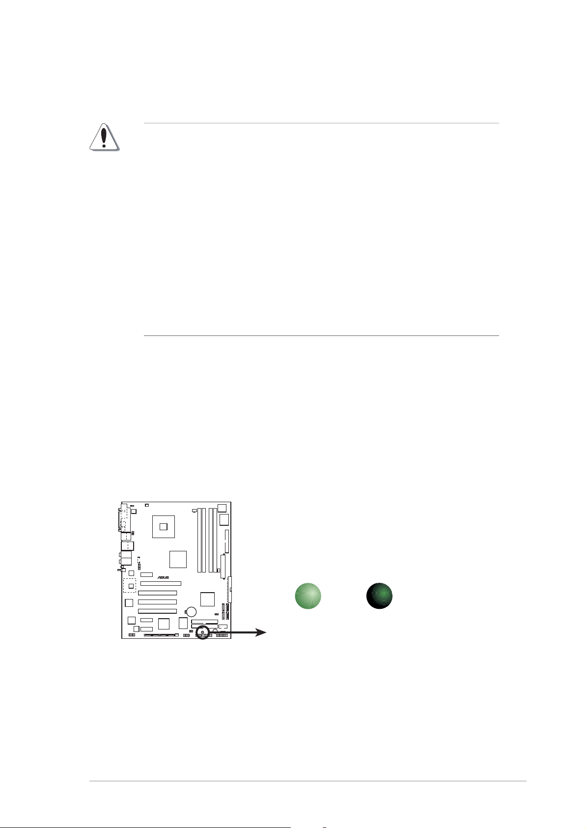
Onboard LEDOnboard LED
Onboard LED
Onboard LEDOnboard LED
The motherboard comes with a standby power LED that lights up to
indicate that the system is ON, in sleep mode, or in soft-off mode.
This is a reminder that you should shut down the system and unplug
the power cable before removing or plugging in any motherboard
component. The illustration below shows the location of the onboard
LED.
P5GD2
®
P5GD2 Deluxe Onboard LED
ON
Standby
Power
SB_PWR1
OFF
Powered
Off
ASUS P5GD2 DeluxeASUS P5GD2 Deluxe
ASUS P5GD2 Deluxe
ASUS P5GD2 DeluxeASUS P5GD2 Deluxe
2-12-1
2-1
2-12-1
2.2 Motherboard overview
Before you install the motherboard, study the configuration of your chassis
to ensure that the motherboard fits into it.
Make sure to unplug the power cord before installing or removing the
motherboard. Failure to do so can cause you physical injury and damage
motherboard components.
2.2.12.2.1
2.2.1
2.2.12.2.1
Placement directionPlacement direction
Placement direction
Placement directionPlacement direction
When installing the motherboard, make sure that you place it into the
chassis in the correct orientation. The edge with external ports goes to the
rear part of the chassis as indicated in the image below.
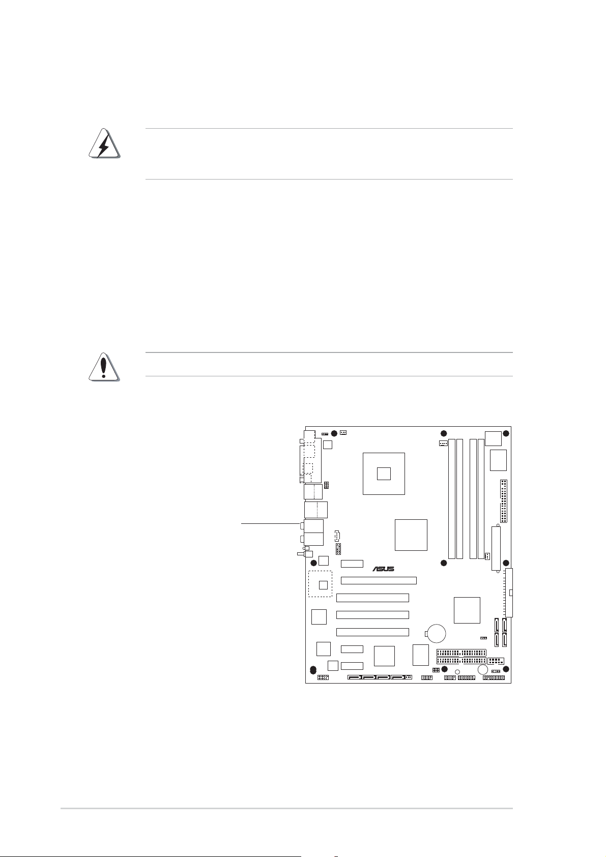
2.2.22.2.2
2.2.2
2.2.22.2.2
Screw holesScrew holes
Screw holes
Screw holesScrew holes
Place nine (9) screws into the holes indicated by circles to secure the
motherboard to the chassis.
Do not overtighten the screws! Doing so can damage the motherboard.
Place this side towardsPlace this side towards
Place this side towards
Place this side towardsPlace this side towards
the rear of the chassisthe rear of the chassis
the rear of the chassis
the rear of the chassisthe rear of the chassis
P5GD2
®
2-22-2
2-2
2-22-2
Chapter 2: Hardware informationChapter 2: Hardware information
Chapter 2: Hardware information
Chapter 2: Hardware informationChapter 2: Hardware information
2.2.32.2.3
2.2.3
2.2.32.2.3
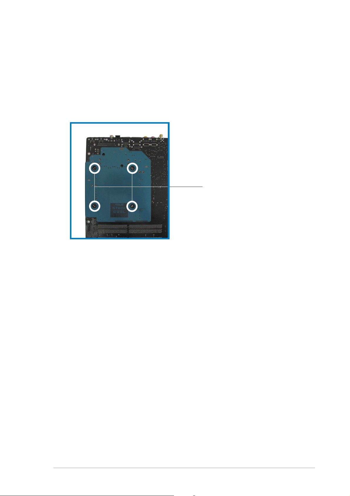
ASUS Stack CoolASUS Stack Cool
ASUS Stack Cool
ASUS Stack CoolASUS Stack Cool
The motherboard comes with ASUS Stack Cool, an innovative thermal
solution that provides supplementary cooling to the motherboard. Stack
Cool is a mini-PCB installed under the motherboard CPU socket to conduct
heat away from motherboard components. Stack Cool effectively lowers
the motherboard temperature by as much as 10ºC.
Motherboard holesMotherboard holes
Motherboard holes
Motherboard holesMotherboard holes
(for the CPU fan and(for the CPU fan and
(for the CPU fan and
(for the CPU fan and(for the CPU fan and
heatsink assembly pins)heatsink assembly pins)
heatsink assembly pins)
heatsink assembly pins)heatsink assembly pins)
ASUS P5GD2 DeluxeASUS P5GD2 Deluxe
ASUS P5GD2 Deluxe
ASUS P5GD2 DeluxeASUS P5GD2 Deluxe
2-32-3
2-3
2-32-3
2.2.42.2.4
2.2.4
2.2.42.2.4
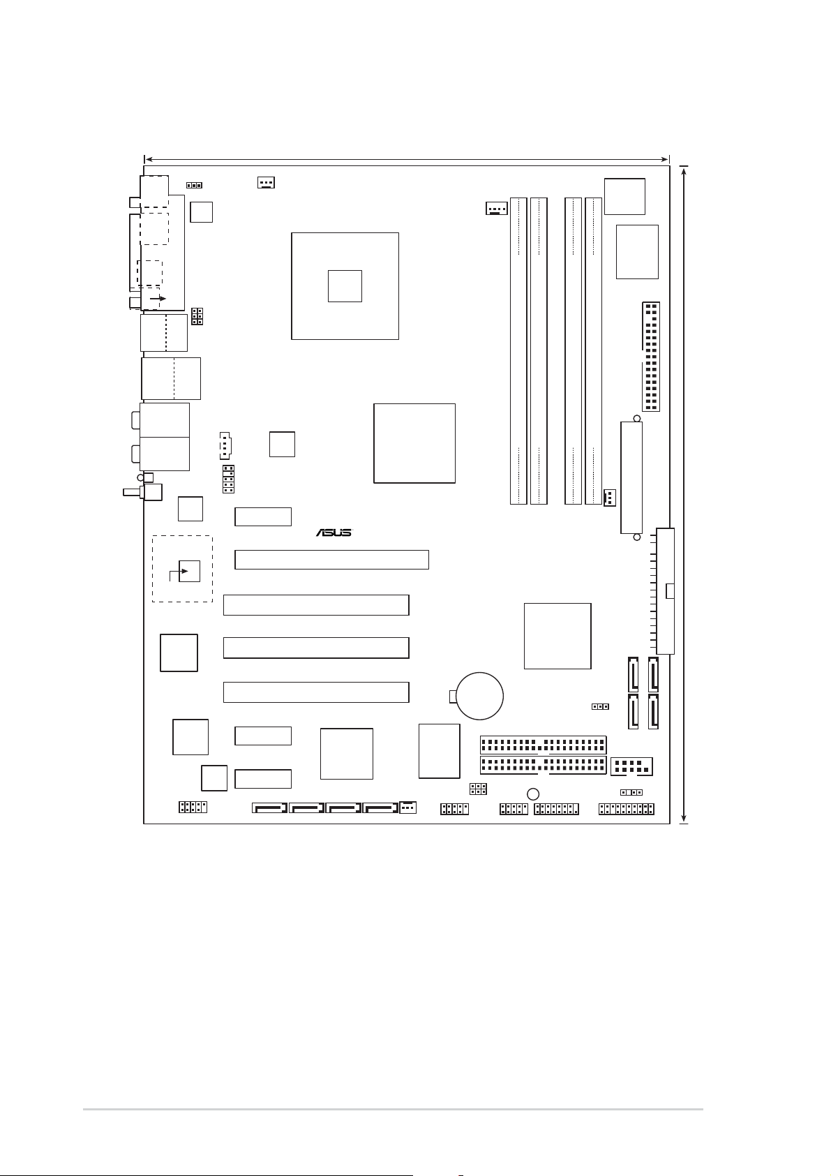
Motherboard layoutMotherboard layout
Motherboard layout
Motherboard layoutMotherboard layout
24.5cm (9.6in)
MS1KB1
SPDIF_O
SPDIF_O2
Bottom:
Top:
USB1
1394
USB2
USB2.0
Top:
T: USB3
RJ-45
B: USB4
Top:
Rear Speaker Out
Center:
Side Speaker Out
Below:
Center/Subwoofer
Top:Line In
Center:Line Out
Below:Mic In
WL_LED
WL_ANT
88W8000G
PARALLEL PORT
C-Media
CMI9880
KBPWR1
ATX12V1
USBPW12
USBPW34
CHA_FAN2
CD
AAFP
PCIEX1_1
Marvell
Gigabit
LAN
PCIEX16
PCI1
Intel
915P
CPU_FAN1
Intel FWH
8Mbit
I/O
Super
FLOPPY1
DDR2 DIMM_A2 (64 bit,240-pin module)
DDR2 DIMM_A1 (64 bit,240-pin module)
DDR2 DIMM_B1 (64 bit,240-pin module)
DDR2 DIMM_B2 (64 bit,240-pin module)
P5GD2
EATXPWR1
PWR_FAN1
PRI_IDE1
30.5cm (12.0in)
Marvell
88W8310
TSB43AB22A
IE1394_2
Speech
Controller
PCI2
PCI3
PCIEX1_2
PCIEX1_3
SATA_RAID1 SATA_RAID2 SATA_RAID3 SATA_RAID4
Silicon Image
SiL 3114R
CHA_FAN1
ITE
8212F
USB56
CR2032 3V
Lithium Cell
CMOS Power
USBPW56
USBPW78
Intel
ICH6R
SEC_RAID1
BUZZ1
SB_PWR1
GAME1USB78
CLRTC1
PRI_RAID1
SATA2
SATA1
COM1
CHASSIS1
PANEL1
SATA4
SATA3
2-42-4
2-4
2-42-4
Chapter 2: Hardware informationChapter 2: Hardware information
Chapter 2: Hardware information
Chapter 2: Hardware informationChapter 2: Hardware information
2.2.52.2.5
2.2.5
2.2.52.2.5
Layout ContentsLayout Contents
Layout Contents
Layout ContentsLayout Contents
SlotsSlots
Slots
SlotsSlots
1. DDR2 DIMM slots 2-13
2. PCI slots 2-18
3. PCI Express slot 2-18
JumpersJumpers
Jumpers
JumpersJumpers
1. Clear RTC RAM (3-pin CLRTC1) 2-19
2. USB Device wake-up (3-pin USBPW12, USBPW34, USBPW56, USBPW78) 2-20
3. Keyboard power (3-pin KBPWR1) 2-21
Rear panel connectorsRear panel connectors
Rear panel connectors
Rear panel connectorsRear panel connectors
1. Parallel port 2-22
2. IEEE 1394 port 2-22
3. RJ-45 port 2-22
4. Rear Speaker Out port 2-22
5. Side Speaker Out port 2-22
6. Line In port 2-22
7. Line Out port 2-22
8. WiFi-g antenna port 2-23
9. Wireless LAN LED 2-23
10. Microphone port 2-23
11. Center/Subwoofer port 2-23
12. USB 2.0 ports 3 and 4 2-23
13. USB 2.0 ports 1 and 2 2-23
14. S/PDIF optical out port 2-23
15. S/PDIF coaxial out port 2-23
16. PS/2 keyboard port 2-23
17. PS/2 mouse port 2-23
PagePage
Page
PagePage
PagePage
Page
PagePage
PagePage
Page
PagePage
ASUS P5GD2 DeluxeASUS P5GD2 Deluxe
ASUS P5GD2 Deluxe
ASUS P5GD2 DeluxeASUS P5GD2 Deluxe
2-52-5
2-5
2-52-5

Internal connectorsInternal connectors
Internal connectors
Internal connectorsInternal connectors
1. Floppy disk drive connector (34-1 pin FLOPPY) 2-24
2. Primary IDE connector (40-1 pin PRI_IDE1) 2-24
3. Primary RAID ATA connector (40-1 pin PRI_RAID1) 2-25
4. Secondary RAID ATA connector (40-1 pin SEC_RAID1) 2-25
5. Serial ATA connectors (7-pin SATA1, SATA2, SATA3, SATA4) 2-26
6. Serial ATA RAID connectors (7-pin SATA_RAID1, SATA_RAID2,
SATA_RAID3, SATA_RAID4) 2-27
7. CPU fan connector (4-pin CPU_FAN1) 2-28
8. Power fan connector (3-pin PWR_FAN1) 2-28
9. Chassis fan connector (3-pin CHA_FAN1) 2-28
10. Chassis fan 2 connector (3-pin CHA_FAN2) 2-28
11. Serial port connector (10-1 pin COM1) 2-29
12. USB headers (10-1 USB56, USB78) 2-29
13. ATX power connector (24-pin EATXPWR1) 2-30
14. ATX 12V power connector (4-pin ATX12V1) 2-30
15. Optical audio connector (4-pin CD) 2-31
16. GAME/MIDI connector (16-1 pin GAME1) 2-31
17. Chassis intrusion connector (4-1 pin CHASSIS1) 2-32
18. Front panel audio connector (10-1 pin AAFP) 2-32
19. System panel connectors (20-1 pin PANEL) 2-33
- System Power LED (Green 3-pin PLED)
- Hard Disk activity (Red 2-pin IDE_LED)
- System warning speaker (Orange 4-pin SPEAKER)
- Power/Soft-off button(Yellow 2-pin PWR)
- Reset switch (Blue 2-pin RESET)
PagePage
Page
PagePage
2-62-6
2-6
2-62-6
Chapter 2: Hardware informationChapter 2: Hardware information
Chapter 2: Hardware information
Chapter 2: Hardware informationChapter 2: Hardware information
 Loading...