


ASUS P4B266-SE User Manual
P4B266
®
User Guide
Motherboard

Checklist
E936
First Edition January 2002
Copyright © 2002 ASUSTeK COMPUTER INC. All Rights Reserved.
No part of this manual, including the products and software described in it, may be
reproduced, transmitted, transcribed, stored in a retrieval system, or translated into any
language in any form or by any means, except documentation kept by the purchaser for
backup purposes, without the express written permission of ASUSTeK COMPUTER INC.
(“ASUS”).
Product warranty or service will not be extended if: (1) the product is repaired, modified or
altered, unless such repair, modification of alteration is authorized in writing by ASUS; or (2)
the serial number of the product is defaced or missing.
ASUS PROVIDES THIS MANUAL “AS IS” WITHOUT WARRANTY OF ANY KIND, EITHER
EXPRESS OR IMPLIED, INCLUDING BUT NOT LIMITED TO THE IMPLIED WARRANTIES
OR CONDITIONS OF MERCHANTABILITY OR FITNESS FOR A PARTICULAR PURPOSE.
IN NO EVENT SHALL ASUS, ITS DIRECTORS, OFFICERS, EMPLOYEES OR AGENTS BE
LIABLE FOR ANY INDIRECT, SPECIAL, INCIDENTAL, OR CONSEQUENTIAL DAMAGES
(INCLUDING DAMAGES FOR LOSS OF PROFITS, LOSS OF BUSINESS, LOSS OF USE
OR DATA, INTERRUPTION OF BUSINESS AND THE LIKE), EVEN IF ASUS HAS BEEN
ADVISED OF THE POSSIBILITY OF SUCH DAMAGES ARISING FROM ANY DEFECT OR
ERROR IN THIS MANUAL OR PRODUCT.
SPECIFICATIONS AND INFORMATION CONTAINED IN THIS MANUAL ARE FURNISHED
FOR INFORMATIONAL USE ONLY, AND ARE SUBJECT TO CHANGE AT ANY TIME
WITHOUT NOTICE, AND SHOULD NOT BE CONSTRUED AS A COMMITMENT BY ASUS.
ASUS ASSUMES NO RESPONSIBILITY OR LIABILITY FOR ANY ERRORS OR
INACCURACIES THAT MAY APPEAR IN THIS MANUAL, INCLUDING THE PRODUCTS
AND SOFTWARE DESCRIBED IN IT.
Products and corporate names appearing in this manual may or may not be registered
trademarks or copyrights of their respective companies, and are used only for identification or
explanation and to the owners’ benefit, without intent to infringe.
ii

Contents
FCC/CDC statements .....................................................................vi
Safety information .......................................................................... vii
About this guide ............................................................................ viii
How this guide is organized.................................................. viii
Conventions used in this guide............................................... ix
Where to find more information .............................................. ix
ASUS contact information ................................................................x
Chapter 1: Product introduction ......................................... 1-1
1.1 Welcome!............................................................................ 1-1
1.2 Package contents ............................................................... 1-1
1.3 Special features .................................................................. 1-2
1.3.1 Product highlights ................................................... 1-2
1.3.2 Value-added solutions ............................................ 1-3
1.4 Overview............................................................................. 1-4
1.4.1 Motherboard components ....................................... 1-4
Chapter 2: Hardware information ........................................ 2-1
2.1 Motherboard installation ...................................................... 2-1
2.1.1 Placement direction ................................................ 2-1
2.1.2 Screw holes............................................................ 2-1
Features
2.2 Motherboard layout ............................................................. 2-2
2.3 Before you proceed............................................................. 2-3
2.4 Central Processing Unit (CPU) ............................................ 2-4
2.4.1 Overview ................................................................ 2-4
2.4.2 Installing the CPU ................................................... 2-5
2.4.3 Installing the heatsink and fan................................. 2-7
2.4.4 Connecting the CPU fan cable................................ 2-9
2.5 System memory ................................................................ 2-10
2.5.1 Overview .............................................................. 2-10
2.5.2 Memory configurations ..........................................2-11
2.5.3 Installing a DIMM ...................................................2-11
2.5.4 Removing a DIMM................................................ 2-12
iii

Safeguards
Contents
2.6 Expansion slots................................................................. 2-13
2.6.1 Installing an expansion card.................................. 2-13
2.6.2 Configuring an expansion card ............................. 2-13
2.6.3 PCI slots ............................................................... 2-15
2.6.4 AGP slot ............................................................... 2-15
2.6.5 CNR slot............................................................... 2-16
2.7 Switches and jumpers ....................................................... 2-17
2.8 Connectors ....................................................................... 2-25
Chapter 3: Powering up ....................................................... 3-1
3.1 Starting up for the first time.................................................. 3-1
3.2 Powering off the computer................................................... 3-2
Chapter 4: BIOS setup ......................................................... 4-1
4.1 Managing and updating your BIOS...................................... 4-1
4.1.1 Using the computer system for the first time ........... 4-1
4.1.2 Updating BIOS procedures ..................................... 4-3
4.2 BIOS Setup program........................................................... 4-5
4.2.1 BIOS menu bar....................................................... 4-6
4.2.2 Legend bar ............................................................. 4-6
4.3 Main Menu .......................................................................... 4-8
4.3.1 Primary and Secondary Master/Slave ..................... 4-9
4.3.2 Keyboard Features ............................................... 4-13
4.4 Advanced Menu ................................................................ 4-15
4.4.1 Chip Configuration ................................................ 4-18
4.4.2 I/O Device Configuration....................................... 4-21
4.4.3 PCI Configuration ................................................. 4-23
4.5 Power Menu...................................................................... 4-25
4.5.1 Power Up Control ................................................. 4-27
4.5.2 Hardware Monitor ................................................. 4-29
4.6 Boot Menu ........................................................................ 4-30
4.7 Exit Menu.......................................................................... 4-33
iv

Contents
Chapter 5: Software support ............................................... 5-1
5.1 Install an operating system.................................................. 5-1
5.2 Support CD information....................................................... 5-1
5.2.1 Running the support CD ......................................... 5-1
5.2.2 Main menu ............................................................. 5-2
5.2.3 Software menu ....................................................... 5-3
5.2.4 Drivers menu .......................................................... 5-5
5.2.5 DOS Utilities menu ................................................. 5-6
5.2.6 ASUS Contact Information...................................... 5-6
5.2.7 Other information .................................................... 5-7
5.3 Software information ........................................................... 5-9
5.3.1 ASUS Update ......................................................... 5-9
5.3.2 ASUS MyLogo™ .................................................. 5-10
5.3.3 Multi-Channel Audio Feature ................................ 5-12
Glossary ................................................................................ G-1
Index ........................................................................................ I-1
v

FCC/CDC statements
Federal Communications Commission Statement
This device complies with FCC Rules Part 15. Operation is subject to the
following two conditions:
• This device may not cause harmful interference, and
• This device must accept any interference received including interference
that may cause undesired operation.
This equipment has been tested and found to comply with the limits for a
Class B digital device, pursuant to Part 15 of the FCC Rules. These limits
are designed to provide reasonable protection against harmful interference
in a residential installation. This equipment generates, uses and can radiate
radio frequency energy and, if not installed and used in accordance with
manufacturer’s instructions, may cause harmful interference to radio
communications. However, there is no guarantee that interference will not
occur in a particular installation. If this equipment does cause harmful
interference to radio or television reception, which can be determined by
turning the equipment off and on, the user is encouraged to try to correct the
interference by one or more of the following measures:
• Reorient or relocate the receiving antenna.
• Increase the separation between the equipment and receiver.
• Connect the equipment to an outlet on a circuit different from that to
which the receiver is connected.
• Consult the dealer or an experienced radio/TV technician for help.
The use of shielded cables for connection of the monitor to the
graphics card is required to assure compliance with FCC regulations.
Changes or modifications to this unit not expressly approved by the
party responsible for compliance could void the user’s authority to
operate this equipment.
Canadian Department of Communications Statement
This digital apparatus does not exceed the Class B limits for radio noise
emissions from digital apparatus set out in the Radio Interference
Regulations of the Canadian Department of Communications.
This class B digital apparatus complies with Canadian ICES-003.
vi

Safety information
Electrical safety
• To prevent electrical shock hazard, disconnect the power cable from
the electrical outlet before relocating the system.
• When adding or removing devices to or from the system, ensure that
the power cables for the devices are unplugged before the signal
cables are connected. If possible, disconnect all power cables from the
existing system before you add a device.
• Before connecting or removing signal cables from the motherboard,
ensure that all power cables are unplugged.
• Seek professional assistance before using an adpater or extension
cord. These devices could interrupt the grounding circuit.
• Make sure that your power supply is set to the correct voltage in your
area. If you are not sure about the voltage of the electrical outlet you
are using, contact your local power company.
• If the power supply is broken, do not try to fix it by yourself. Contact a
qualified service technician or your retailer.
Operation safety
• Before installing the motherboard and adding devices on it, carefully
read all the manuals that came with the package.
• Before using the product, make sure all cables are correctly connected
and the power cables are not damaged. If you detect any damage,
contact your dealer immediately.
• To avoid short circuits, keep paper clips, screws, and staples away from
connectors, slots, sockets and circuitry.
• Avoid dust, humidity, and temperature extremes. Do not place the
product in any area where it may become wet.
• Place the product on a stable surface.
• If you encounter technical problems with the product, contact a
qualified service technician or your retailer.
vii

About this guide
This user guide contains the information you need when installing the
ASUS P4B266 motherboard.
How this guide is organized
This manual contains the following parts:
• Chapter 1: Product introduction
This chapter describes the features of the P4B266 motherboard. It
includes brief descriptions of the special attributes of the motherboard
and the new technology it supports.
• Chapter 2: Hardware information
This chapter lists the hardware setup procedures that you have to
perform when installing system components. It includes description of
the switches, jumpers, and connectors on the motherboard.
• Chapter 3: Powering up
This chapter describes the power up sequence and gives information
on the BIOS beep codes.
• Chapter 4: BIOS setup
This chapter tells how to change system settings through the BIOS
Setup menus. Detailed descriptions of the BIOS parameters are also
provided.
• Chapter 5: Software support
This chapter describes the contents of the support CD that comes with
the motherboard package.
• Glossary
This part lists the technical terms that you may encounter when
reading this document.
• Index
This part contains an alphabetical list of the topics found in this
document.
viii
Conventions used in this guide
To make sure that you perform certain tasks properly, take note of the
following symbols used throughout this manual.
WARNING: Information to prevent injury to yourself when trying
to complete a task.
CAUTION: Information to prevent damage to the components
when trying to complete a task.
IMPORTANT: Information that you MUST follow to complete a
task.
NOTE: Tips and additional information to aid in completing a task.
Where to find more information
Refer to the following sources for additional information and for product
and software updates.
1. ASUS Websites
The ASUS websites worldwide provide updated information on ASUS
hardware and software products. The ASUS websites are listed in the
ASUS Contact Information on page x.
2. Optional Documentation
Your product package may include optional documentation, such as
warranty flyers, that may have been added by your dealer. These
documents are not part of the standard package.
ix

ASUS contact information
ASUSTeK COMPUTER INC. (Asia-Pacific)
Address: 150 Li-Te Road, Peitou, Taipei, Taiwan 112
General Tel: +886-2-2894-3447
General Fax: +886-2-2894-3449
General Email: info@asus.com.tw
Technical Support
MB/Others (Tel): +886-2-2890-7121 (English)
Notebook (Tel): +886-2-2890-7122 (English)
Desktop/Server (Tel): +886-2-2890-7123 (English)
Support Fax: +886-2-2890-7698
Support Email: tsd@asus.com.tw
Web Site: www.asus.com.tw
Newsgroup: cscnews.asus.com.tw
ASUS COMPUTER INTERNATIONAL (America)
Address: 6737 Mowry Avenue, Mowry Business Center,
Building 2, Newark, CA 94560, USA
General Fax: +1-510-608-4555
General Email: tmd1@asus.com
Technical Support
Support Fax: +1-510-608-4555
Notebook (Tel): 1-877-918-ASUS (2787)
Web Site: www.asus.com
Support Email: tsd@asus.com
ASUS COMPUTER GmbH (Europe)
Address: Harkortstr. 25, 40880 Ratingen, BRD, Germany
General Fax: +49-2102-442066
General Email: sales@asuscom.de (for marketing requests only)
Technical Support
Support Hotline: MB/Others: +49-2102-9599-0
Notebook (Tel): +49-2102-9599-10
Support Fax: +49-2102-9599-11
Support (Email): www.asuscom.de/de/support (for online support)
Web Site: www.asuscom.de
x
Chapter 1
This chapter describes the features of the
P4B266
explanations of the special attributes of the
motherboard and the new technology it
supports.
motherboard. It includes brief
Product introduction

ASUS P4B266 motherboard
1.1 Welcome!
Thank you for buying the ASUS® P4B266 motherboard!
The ASUS
motherboard – minus some onboard features including USB 2.0, LAN,
POST Reporter™, and Memory Stick/Secure Digital interfaces.
P4B266 motherboard is basically an ASUS P4B266
This motherboard incorporates the Intel
package/Northwood Processor coupled with the Intel
chipset to set a new benchmark for an effective desktop platform solution.
Supporting up to 2GB of system memory with PC2100/1600 DDR
SDRAM, high-resolution graphics via an AGP 4X slot, communication and
networking options through a CNR slot, high-speed data transfers using
the ATA100 protocol, and enhanced PCI audio features, this motherboard
is your affordable vehicle to power computing!
Before you start installing the motherboard, and hardware devices on it,
check the items in your package with the list below.
®
Pentium® 4 Processor in 478-pin
®
845D (Brookdale)
1.2 Package contents
Check your P4B266 package for the following items.
ASUS P4B266
motherboard (ATX form factor: 12-in x 9.4-in)
ASUS P4B266 series support CD
ASUS 2-port USB 1.1 module
ASUS S/PDIF module (for audio models only)
80-conductor ribbon cable for UltraDMA/33/66/100 IDE drives
40-conductor IDE cable
Ribbon cable for a 3.5-inch floppy drive
Bag of extra jumper caps
User Guide
Quick Setup Guide and Reference Card (retail box only)
Jumpers and Connectors Sticker (retail box only)
If any of the above items is damaged or missing, contact your retailer.
ASUS P4B266 motherboard user guide
1-1

1.3 Special features
1.3.1 Product highlights
Latest processor technology
The P4B266 motherboard supports the latest Intel Pentium 4 478/
Northwood Processor, also known as P4, via a 478-pin surface mount ZIF
socket. The Pentium 4 processor utilizes the advanced 0.18 micron
processor core in FC-PGA2 package for a 2.0GHz frequency, while the
Northwood processor uses the 0.13 micron processor core with 512KB L2
cache for up to a speedy 2.4+GHz frequency. The P4 offers optimized
performance for audio, video, and Internet applications. See page 2-4.
DDR memory support
Employing the Double Data Rate (DDR) memory technology, the P4B266
motherboard supports up to 2GB of system memory using PC2100/1600
DDR DIMMs. The ultra-fast 266MHz memory bus doubles the speed of the
PC133 SDRAM to deliver the required bandwidth for the latest 3D
graphics, multimedia, and Internet applications. See page 2-10.
ASUS MyLogo™
This new feature present in the P4B266 motherboard allows you to
personalize and add style to your system with customizable boot logos.
See section “5.3.2 ASUS MyLogo” on page 5-10.
ASUS EZ Plug™
This patented ASUS technology lets you use your existing power supply
rather than buying a new ATX 12V power supply. The ASUS EZ Plug™ is
a 4-pin auxillary +12V connector mounted on the motherboard that
connects a regular 4-pin device power connector from the power supply.
This connector is necessary to provide the additional power required by
the P4 CPU. Refer to page 2-28.
Digital audio interface
On audio models, a digital audio connector is onboard to accommodate
the Sony/Philips Digital Interface (S/PDIF) In/Out module, which supports
coaxial interfaces. Experience 5.1-channel surround sound and enhanced
3D audio while playing DVDs and computer games. See page 2-32.
1-2
Chapter 1: Product introduction

1.3.2 Value-added solutions
Overclocking
The P4B266 overclocking features:
• adjustable CPU frequency multiple in BIOS using the ASUS
JumperFree™ solution
• adjustable FSB/DDR frequency ratio
• Stepless Frequency Selection (SFS) for fine-tuning system bus
frequency from 100MHz up to 200MHz at 1MHz increments
• optimized system performance through BIOS built-in optimization mode
• adjustable CPU V
and DDR memory voltage
CORE
ASUS iPanel support
The motherboard supports the ASUS iPanel to provide easy connectivity,
one-touch management of various peripherals, and convenient monitoring
of system status.
ASUS P4B266 motherboard user guide
1-3

1.4 Overview
Before you install the P4B266 motherboard, familiarize yourself with its
physical configuration and available features to facilitate the motherboard
installation and future upgrades. A sufficient knowledge of the motherboard
specifications will also help you avoid mistakes that may damage the
board and its components.
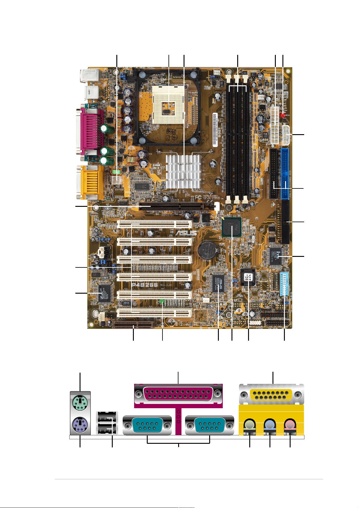
1.4.1 Motherboard components
The following are the major components of the P4B266 motherboard as
pointed out in the picture on page 1-5.
1. ATX 12V connector
2. CPU socket
3. North Bridge controller
4. DDR DIMM sockets
5. ATX power connector
6. AGP warning LED
7. ASUS EZ Plug™ auxilliary +12V
connector
8. IDE connectors
9. Floppy connector
10. Super I/O controller
11. DIP switches
12. Flash EEPROM
13. South Bridge controller
14. ASUS ASIC
15. Onboard LED
20. PS/2 mouse port
21. Parallel port
22. Game/MIDI port (optional)
23. Microphone jack (optional)
24. Line In jack (optional)
25. Line Out jack (optional)
26. Serial ports
27. USB ports
28. Keyboard port
1-4
16. CNR slot
17. Audio controller (optional)
18. PCI slots
19. AGP slot
See page 1-6 for a brief description of each component. Refer to
Chapter 2 for detailed information on the motherboard components.
Chapter 1: Product introduction
19
1
23 4
5 6
7
8
9
18
17
15 13
20 21 22
14 1116
12
10
ASUS P4B266 motherboard user guide
23242528 2627
1-5

1
ATX 12V connector. This power connector connects the 4-pin 12V
plug from the ATX 12V power supply.
2
CPU socket. A 478-pin surface mount, Zero Insertion Force (ZIF)
socket called mPGA478 B. This socket accommodates the Intel
®
Pentium® 4 478/Northwood Processor with 400MHz system bus.
3
North bridge controller. This controller called the Intel Memory
Controller Hub (MCH) is one of the two major components of the
Intel 845D (Brookdale) chipset. The MCH and the south bridge Intel
I/O Controller Hub 2 (ICH2) are interconnected through the Intel
proprietary Hub interface. The MCH provides the processor
interface, memory interface, AGP interface, and Hub Interface.
4
DDR DIMM sockets. These three 184-pin DIMM sockets support
up to 2GB using unbuffered ECC or non-ECC PC2100/1600 DDR
DIMMs.
5
ATX power connector. This 20-pin connector connects to an ATX
+12V power supply. The power supply must have at least 1A on the
+5V standby lead (+5VSB).
6
AGP warning LED. Serving as a smart burn-out protection for the
motherboard, this red LED lights up if you plug in any 3.3V AGP
card into the AGP slot. When this LED is lit, there is no way you
can turn on the system power even if you press the power button.
7
ASUS EZ Plug™ Auxilliary +12V connector. This ASUS patented
auxilliary power connector is used if you don’t have an ATX +12V
power supply. Connect a 4-pin device connector from a standard
power supply to this connector to provide sufficient power to the
CPU.
8
IDE connectors. These dual-channel bus master IDE connectors
support up to four Ultra DMA/100/66, PIO Modes 3 & 4 IDE
devices. Both the primary (blue) and secondary (black) connectors
are slotted to prevent incorrect insertion of the IDE ribbon cable.
9
Floppy disk connector. This connector accommodates the
provided ribbon cable for the floppy disk drive. One side of the
connector is slotted to prevent incorrect insertion of the floppy disk
cable.
1-6
Chapter 1: Product introduction

10
Super I/O controller. This Low Pin Count (LPC) interface provides
the commonly used Super I/O functionality. The chipset supports a
high-performance floppy disk controller for a 360K/720K/1.44M/
2.88M floppy disk drive, a multi-mode parallel port, two standard
compatible UARTs, a Standard Infrared (SIR), one MPU-401 UART
mode compatible MIDI/game port, and a Flash ROM interface.
11
12
13
14
15
DIP switches. This 10-switch Dual Inline Package (DIP) allows you
to set the CPU external frequency.
Flash EEPROM. This 2Mb firmware contains the programmable
BIOS program.
South bridge controller. Referred to as the Intel I/O Controller
Hub 2 (ICH2) of the Intel 845D chipset, this controller provides the
I/O subsystem that allows access to the rest of the system. The
ICH2 integrates I/O functions such as system bus interface, Ultra
ATA/100, Low Pin Count (LPC) interface, Universal Serial Bus
(USB) 1.1 interface, PCI interface, and CNR interface.
ASUS ASIC. This chip performs multiple system functions that
include hardware and system voltage monitoring, IRQ routing,
among others.
Onboard LED. This onboard LED lights up if there is a standby
power on the motherboard. This LED acts as a reminder to turn off
the system power before plugging or unplugging devices.
16
17
18
19
CNR slot. This slot is specifically designed for the Communications
and Networking Riser (CNR) card. The CNR supports V.90 analog
modem, HPNA, USB Hub, and the 10BASE-T/100BASE-TX
Ethernet networking.
Audio controller. This C-Media 6-channel PCI audio chip supports
legacy audio and HRTF 3D positional audio functions. The chip
also supports 24-bit S/PDIF In (0.5~5V) and S/PDIF Out (44.1K
and 48K formats) professional digital audio interface.
(on audio models only)
PCI slots. These six 32-bit PCI 2.2 expansion slots support bus
master PCI cards like SCSI or LAN cards with 133MB/s maximum
throughput.
AGP slot. This Accelerated Graphics Port (AGP) slot supports 1.5V
AGP4X mode graphics cards for 3D graphical applications.
ASUS P4B266 motherboard user guide
1-7

20
PS/2 mouse port. This green 6-pin connector is for a PS/2 mouse.
21
22
23
24
25
26
Parallel port. This 25-pin port connects a parallel printer, a
scanner, or other devices.
Game/MIDI port. This connector supports a joystick or a game pad
for playing games, and MIDI devices for playing or editing audio
files.
Microphone jack. This Mic (pink) jack connects a microphone. In
6-channel mode, the function of this jack becomes Bass/Center.
(on audio models only)
(on audio models only)
Line In jack. This Line In (light blue) jack connects a tape player or
other audio sources. In 6-channel mode, the function of this jack
becomes Rear Speaker Out.
Line Out jack. This Line Out (lime) jack connects a headphone or
a speaker. In 6-channel mode, the function of this jack becomes
Front Speaker Out.
Serial ports. These two 9-pin COM1/COM2 ports are for pointing
devices or other serial devices.
(on audio models only)
(on audio models only)
27
28
USB ports. These two 4-pin Universal Serial Bus (USB) ports are
available for connecting USB devices such as a mouse and PDA.
PS/2 keyboard port. This purple 6-pin connector is for a PS/2
keyboard.
1-8
Chapter 1: Product introduction
Chapter 2
This chapter describes the hardware setup
procedures that you have to perform when
installing system components. It includes
details on the switches, jumpers, and
connectors on the motherboard.
Hardware information

ASUS P4B266 motherboard
2.1 Motherboard installation
Before you install the motherboard, study the configuration of your chassis
to ensure that the motherboard fits into it. The P4B266 uses the ATX form
factor that measures 12 inches x 9.4 inches, a standard fit for most
chassis.
Make sure to unplug the power cord before installing or removing the
motherboard. Failure to do so may cause you physical injury and
damage motherboard components.
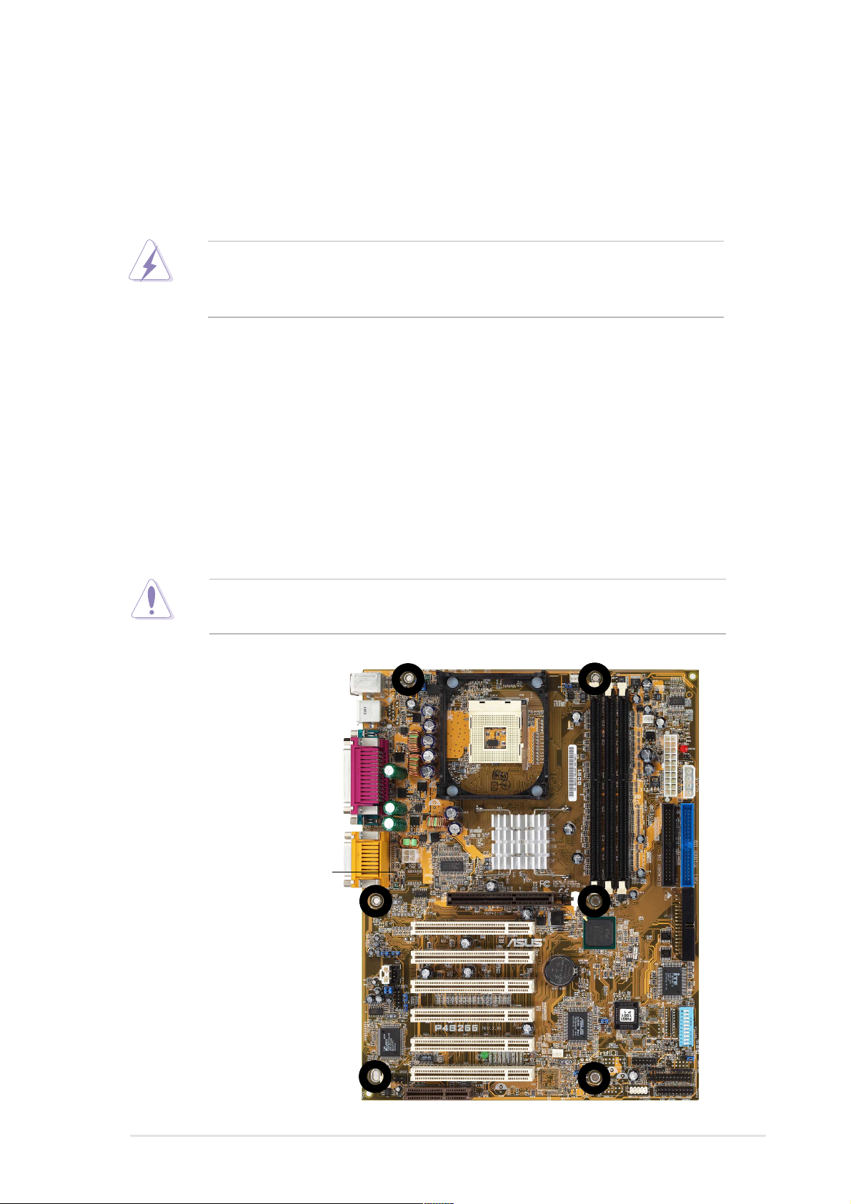
2.1.1 Placement direction
When installing the motherboard, make sure that you place it into the
chassis in the correct orientation. The edge with external ports goes to the
rear part of the chassis. Refer to the image below.
2.1.2 Screw holes
Place six (6) screws into the holes indicated by circles to secure the
motherboard to the chassis.
Do not overtighten the screws! Doing so may damage the
motherboard.
Place this side towards
the rear of the chassis
ASUS P4B266 motherboard user guide
2-1
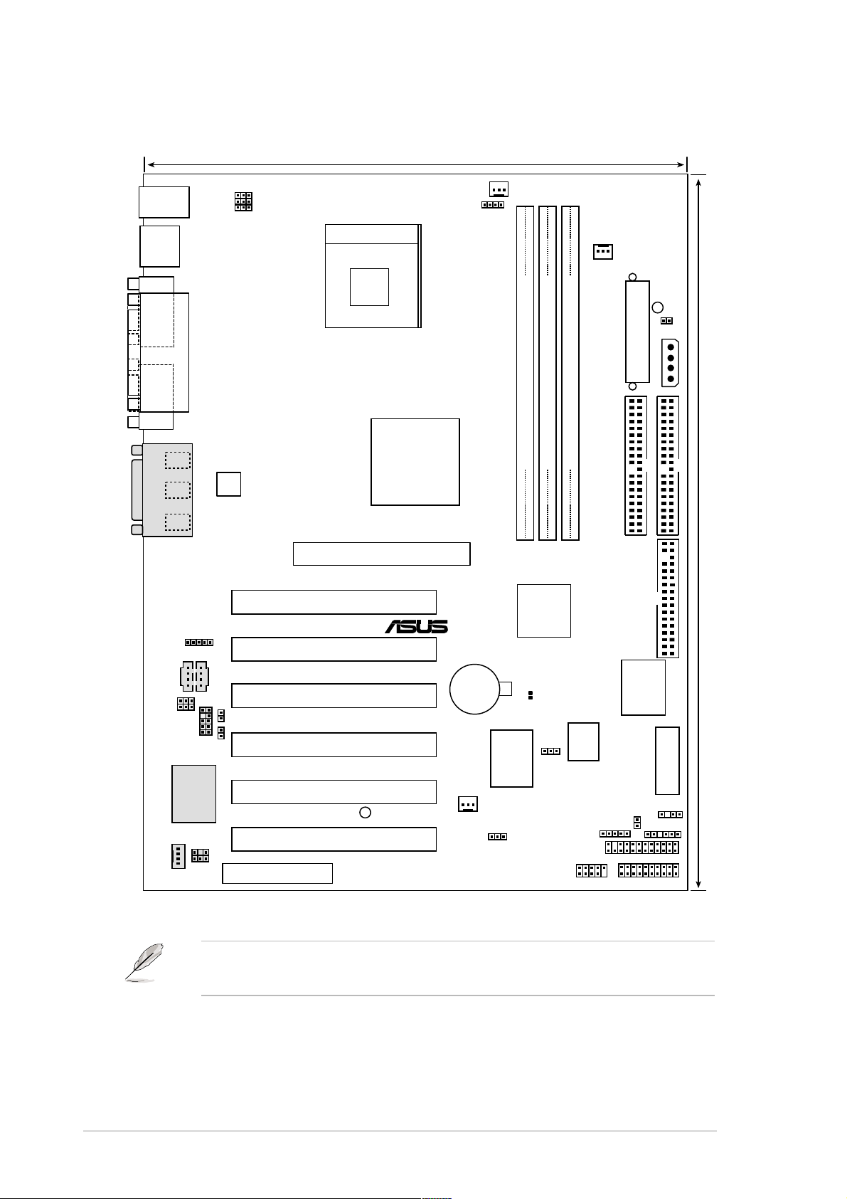
2.2 Motherboard layout
24cm (9.4in)
PS/2KBMS
T: Mouse
B: Keyboard
USB
T: USB1
B: USB2
COM1
PARALLEL PORT
COM2
Line
Out
Line
In
Mic
GAME_AUDIO
In
LINE_IN
BCS1
BCS2
IAPANEL
C-Media
SPDIF_C
MODEM
ATX12V
CDAUX
LO_L
LO_R
CMI8738 6CH
Audio Controller
KBPWR
USBPWR01
OVER_VOLT
P4B266
CNR
Socket 478
Intel 845D
Memory
Controller
Hub (MCH)
Accelerated Graphics Port
AGP
PCI1
PCI2
PCI3
PCI4
PCI5
LED1
PCI6
CPU_FAN
®
CR2032 3V
Lithium Cell
CMOS Power
USBPWR23
DDR_OV
Hardware
Monitor
CH_FAN
PWRFAN
ATX Power Connector
Hub
Firmware
IR
SECONDARY IDE
Super
I/O
CHASSIS
HDDLED
DDR DIMM2 (64/72 bit, 184-pin module)
DDR DIMM1 (64/72 bit, 184-pin module)
0 1
Intel I/O
Controller
(ICH2)
CLRTC(R197)
ASUS
ASIC
with
DDR DIMM2 (64/72 bit, 184-pin module)
2 3
2 3
Hub
2Mbit
JEN
AFPANEL
USB11_23
WARNING
TRPWR
EZ_PLUG
PRIMARY IDE
30.5cm (12.0in)
FLOPPY
SWITCH
SMB
PANEL
2-2
The audio features are optional. These components are grayed out in
the above motherboard layout.
Chapter 2: Hardware information
2.3 Before you proceed
Take note of the following precautions before you install motherboard
components or change any motherboard settings.
1. Unplug the power cord from the wall socket before touching any
component.
2. Use a grounded wrist strap or touch a safely grounded object or to
a metal object, such as the power supply case, before handling
components to avoid damaging them due to static electricity.
3. Hold components by the edges and do not to touch the ICs on them.
4. Whenever you uninstall any component, place it on a grounded
antistatic pad or in the bag that came with the component.
5. Before you install or remove any component, ensure that the
ATX power supply is switched off or the power cord is
detached from the power supply. Failure to do so may cause
severe damage to the motherboard, peripherals, and/or
components.
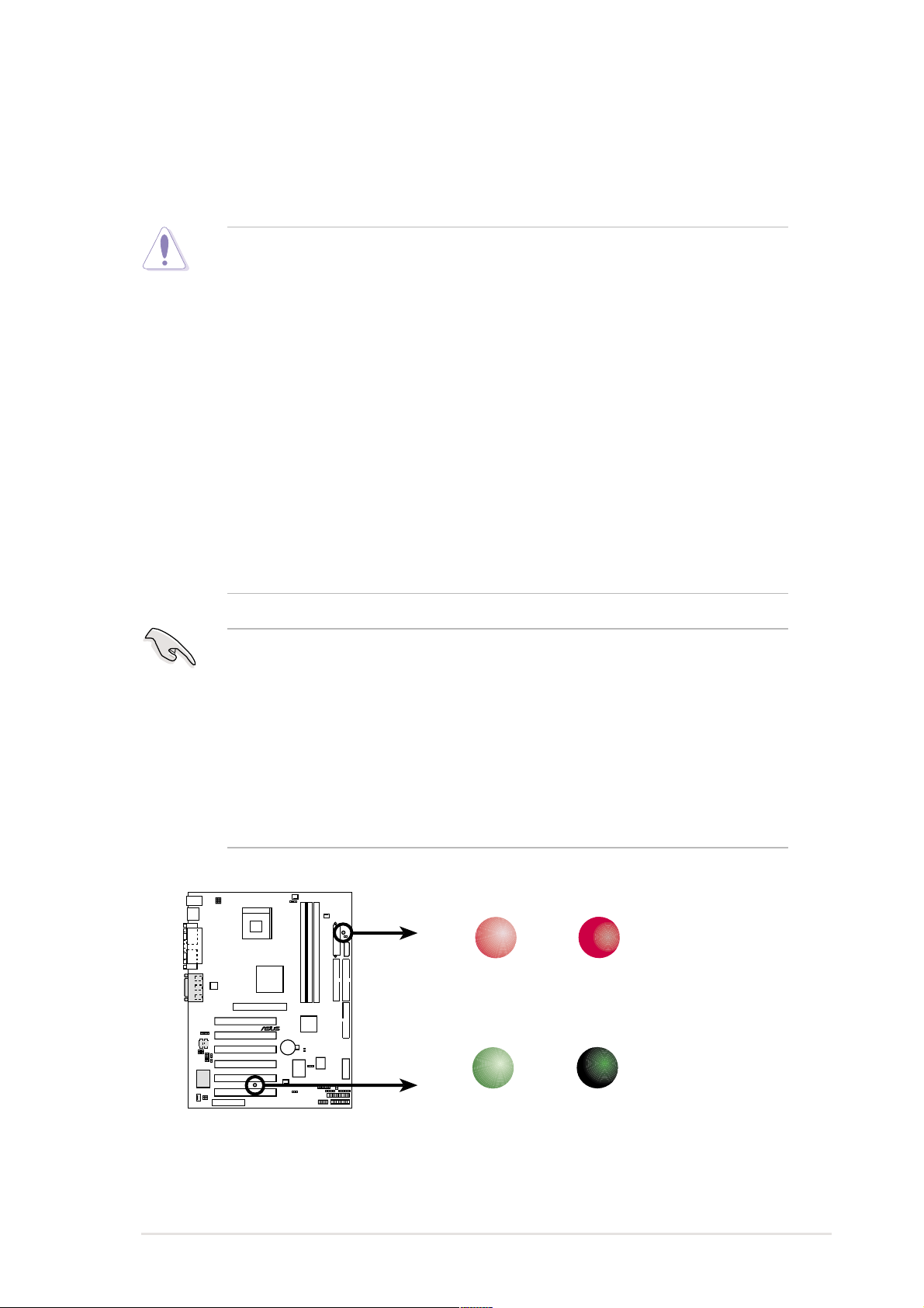
When lit, the green LED (LED1) indicates that the system is ON, in
sleep mode, or in soft-off mode, a reminder that you should shut down
the system before removing of plugging in any motherboard
component.
The red LED (WARNING) is a smart protection from motherboard burn
out caused by an incorrect AGP card. If you plug in any 3.3V AGP card
into the 1.5V AGP slot, this LED lights up thus preventing the system to
power up. This LED remains off if you plug in a 1.5V AGP card.
WARNING
P4B266
ON
Incorrect
AGP Card
®
LED1
OFF
Correct
AGP Card
ON
P4B266 Onboard LED
Standby
Power
ASUS P4B266 motherboard user guide
OFF
Powered
Off
2-3
2.4 Central Processing Unit (CPU)
2.4.1 Overview
The motherboard comes with a surface mount 478-pin Zero Insertion
Force (ZIF) socket. This socket is specifically designed for the Intel
Pentium® 4 478/Northwood Processor.
The Intel Pentium 4 Processor in the 478-pin package uses the Flip-Chip
Pin Grid Array 2 (FC-PGA2) package technology, and includes the Intel
NetBurst™ micro-architecture. The Intel NetBurst micro-architecture
features the hyper-pipelined technology, rapid execution engine, 400MHz
system bus, and execution trace cache. Together, these attributes improve
system performance by allowing higher processor frequencies, faster
execution of integer instructions, and a data transfer rate of 3.2GB/s.
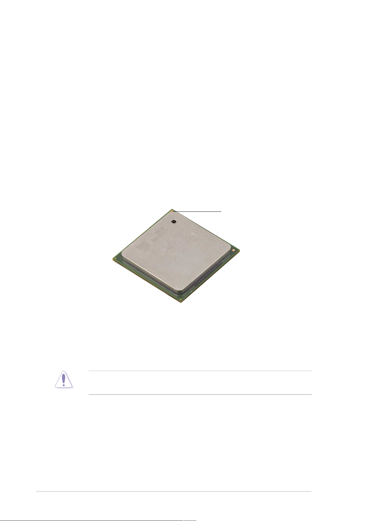
Gold Mark
®
®
Note in the illustration that the CPU has a gold triangular mark on one
corner. This mark indicates the processor Pin 1 that should match a
specific corner of the CPU socket.
Incorrect installation of the CPU into the socket may bend the pins and
severely damage the CPU!
2-4
Chapter 2: Hardware information
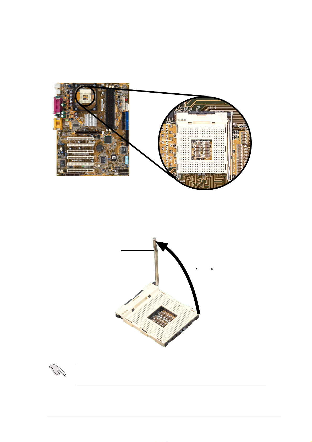
2.4.2 Installing the CPU
Follow these steps to install a CPU.
1. Locate the 478-pin ZIF socket on the motherboard.
2. Unlock the socket by pressing the lever sideways, then lift it up to a
90°-100° angle.
Socket Lever
90 -100
Make sure that the socket lever is lifted up to 90°-100° angle,
otherwise the CPU does not fit in completely.
ASUS P4B266 motherboard user guide
2-5
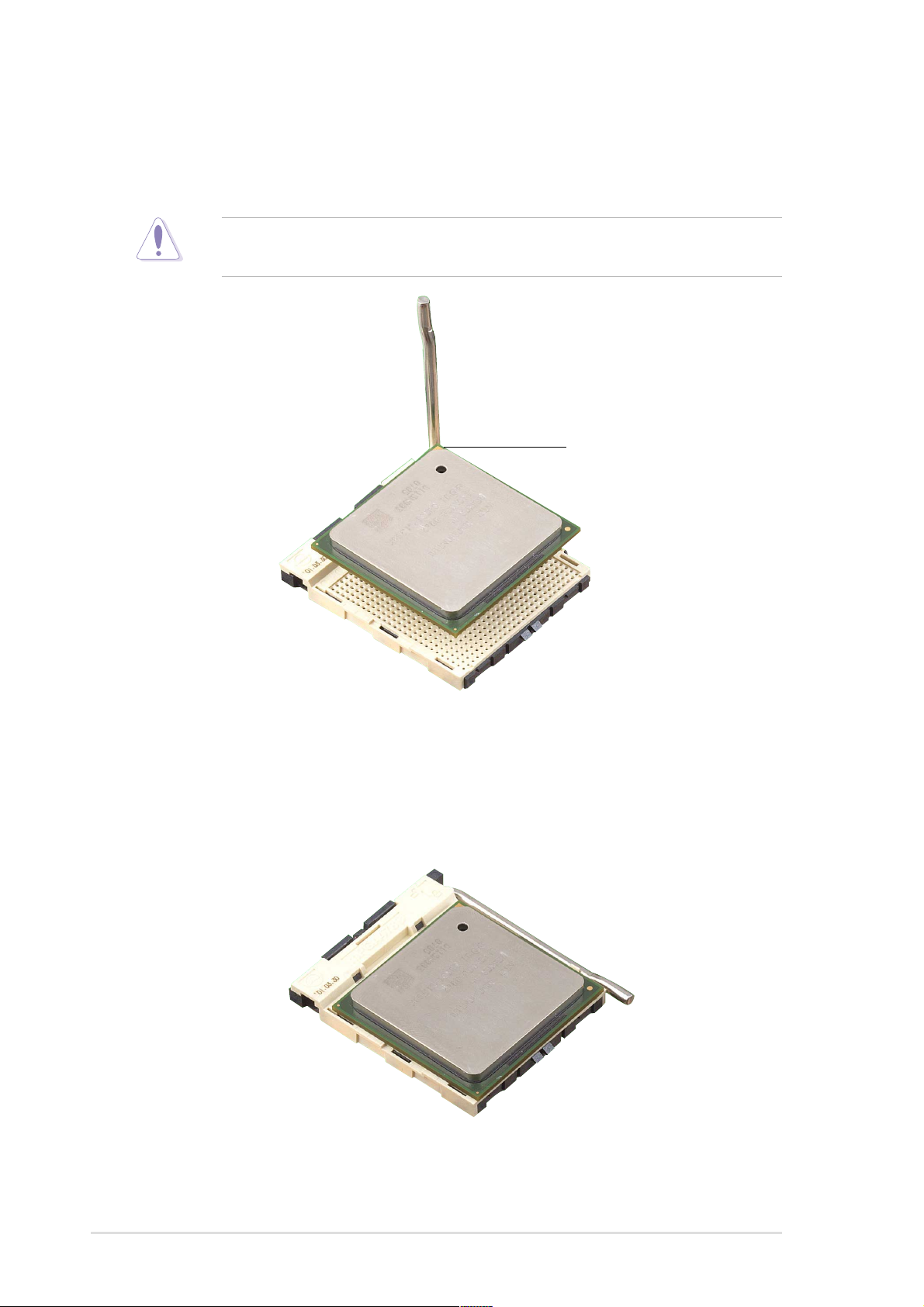
3. Position the CPU above the socket such that its marked corner
matches the base of the socket lever.
4. Carefully insert the CPU into the socket until it fits in place.
The CPU fits only in one correct orientation. DO NOT force the CPU
into the socket to prevent bending the pins and damaging the CPU!
Gold Mark
5. When the CPU is in place, press it firmly on the socket while you push
down the socket lever to secure the CPU. The lever clicks on the side
tab to indicate that it is locked.
2-6
Chapter 2: Hardware information
2.4.3 Installing the heatsink and fan
The Intel® Pentium® 4 478/Northwood Processor requires a specially
designed heatsink and fan assembly to ensure optimum thermal condition
and performance.
When you buy a boxed Intel Pentium 4 478/Northwood Processor, the
package includes the heatsink, fan, and retention mechanism.
In case you buy a CPU separately, make sure that you use only Intel
certified heatsink and fan.
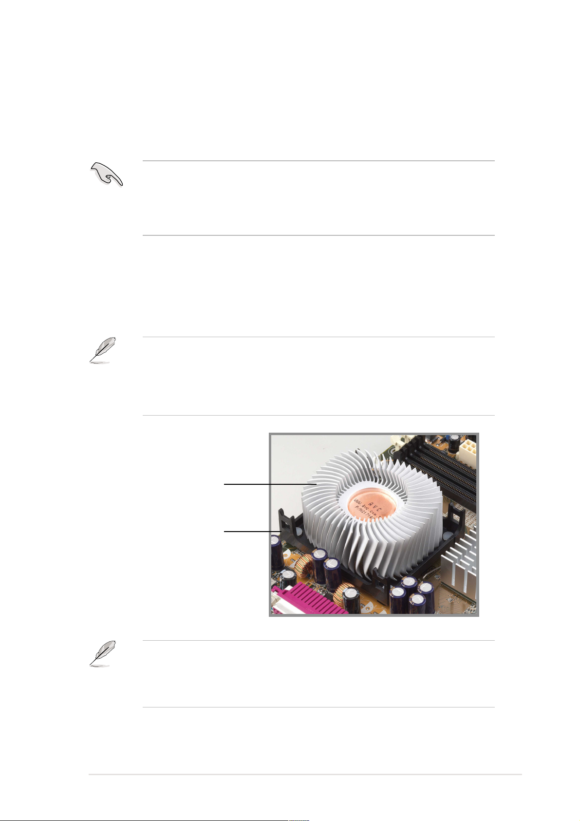
Follow these steps to install the CPU heatsink and fan.
1. Place the heatsink on top of the installed CPU, making sure that the
heatsink fits properly on the retention module base.
The retention module base is already installed on the motherboard
upon purchase.
You do not have to remove the retention module base when installing
the CPU or installing other motherboard components.
CPU Heatsink
Retention Module Base
Your boxed Intel Pentium 4 478/Northwood Processor package should
come with installation instructions for the CPU, heatsink, and the
retention mechanism. If the instructions in this section do not match the
CPU documentation, follow the latter.
ASUS P4B266 motherboard user guide
2-7
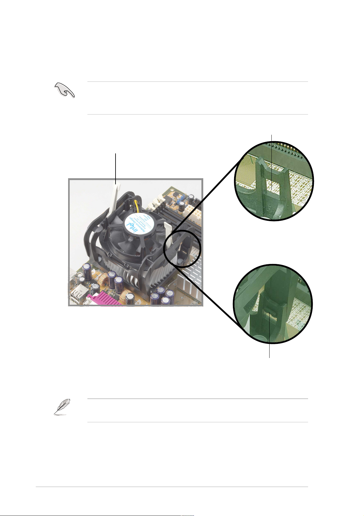
2. Position the fan with the retention mechanism on top of the heatsink.
Align and snap the four hooks of the retention mechanism to the holes
on each corner of the module base.
Make sure that the fan and retention mechanism assembly perfectly
fits the heatsink and module base, otherwise you cannot snap the
hooks into the holes.
Retention Hole
Retention Lock
2-8
Retention Hook Snapped
to the Retention Hole
Keep the retention locks lifted upward while fitting the retention
mechanism to the module base.
Chapter 2: Hardware information
 Loading...