


ASUS P3WE User Manual

®
P3W-E
Intel® 810e Motherboard
USER’S MANUAL

USER'S NOTICE
No part of this manual, including the products and software described in it, may be reproduced, transmitted, transcribed, stored in a retrieval system, or translated into any language in
any form or by any means, except documentation kept by the purchaser for backup purposes,
without the express written permission of ASUSTeK COMPUTER INC. (“ASUS”).
ASUS PROVIDES THIS MANUAL “AS IS” WITHOUT WARRANTY OF ANY KIND,
EITHER EXPRESS OR IMPLIED, INCLUDING BUT NOT LIMITED T O THE IMPLIED
WARRANTIES OR CONDITIONS OF MERCHANT ABILITY OR FITNESS FOR A PARTICULAR PURPOSE. IN NO EVENT SHALL ASUS, ITS DIRECTORS, OFFICERS,
EMPLOYEES OR AGENTS BE LIABLE FOR ANY INDIRECT, SPECIAL, INCIDENTAL, OR CONSEQUENTIAL DAMAGES (INCLUDING DAMAGES FOR LOSS OF
PROFITS, LOSS OF BUSINESS, LOSS OF USE OR DATA, INTERRUPTION OF BUSINESS AND THE LIKE), EVEN IF ASUS HAS BEEN ADVISED OF THE POSSIBILITY
OF SUCH DAMAGES ARISING FROM ANY DEFECT OR ERROR IN THIS MANUAL
OR PRODUCT.
Product warranty or service will not be extended if: (1) the product is repaired, modified or
altered, unless such repair, modification of alteration is authorized in writing by ASUS; or (2)
the serial number of the product is defaced or missing.
Products and corporate names appearing in this manual may or may not be registered trademarks or copyrights of their respective companies, and are used only for identification or
explanation and to the owners’ benefit, without intent to infringe.
• QuickStart and JumperFree are trademarks of ASUSTeK Computer Inc.
• Intel, LANDesk, and Pentium are registered trademarks of Intel Corporation.
• IBM and OS/2 are registered trademarks of International Business Machines.
• XGstudio and SoftSynthesizer are registered trademarks of Yamaha Corporation.
• Symbios is a registered trademark of Symbios Logic Corporation.
• Windows and MS-DOS are registered trademarks of Microsoft Corporation.
• Adobe and Acrobat are registered trademarks of Adobe Systems Incorporated.
The product name and revision number are both printed on the product itself. Manual revi-
sions are released for each product design represented by the digit before and after the period
of the manual revision number. Manual updates are represented by the third digit in the manual
revision number.
For previous or updated manuals, BIOS, drivers, or product release information, contact ASUS
at http://www.asus.com.tw or through any of the means indicated on the following page.
SPECIFICATIONS AND INFORMATION CONTAINED IN THIS MANUAL ARE FURNISHED FOR INFORMATIONAL USE ONLY, AND ARE SUBJECT TO CHANGE AT
ANY TIME WITHOUT NOTICE, AND SHOULD NOT BE CONSTRUED AS A COMMITMENT BY ASUS. ASUS ASSUMES NO RESPONSIBILITY OR LIABILITY FOR
ANY ERRORS OR INACCURACIES THAT MA Y APPEAR IN THIS MANUAL, INCLUDING THE PRODUCTS AND SOFTWARE DESCRIBED IN IT.
Copyright © 1999 ASUSTeK COMPUTER INC. All Rights Reserved.
Product Name: ASUS P3W-E
Manual Revision: 1.02 E451
Release Date: September 1999
2 ASUS P3W-E User’s Manual

ASUS CONTACT INFORMATION
ASUSTeK COMPUTER INC. (Asia-Pacific)
Marketing
Address: 150 Li-Te Road, Peitou, Taipei, Taiwan 112
Telephone: +886-2-2894-3447
Fax: +886-2-2894-3449
Email: info@asus.com.tw
Technical Support
MB/Cards (tel): English: +886-2-2890-7121
Notebook (tel): English: +886-2-2890-7122
Server (tel): English: +886-2-2890-7123
Fax: +886-2-2895-9254
Email: tsd@asus.com.tw
Newsgroup: news2.asus.com.tw
WWW: www.asus.com.tw
FTP: ftp.asus.com.tw/pub/ASUS
ASUS COMPUTER INTERNATIONAL (America)
Marketing
Address: 6737 Mowry Avenue, Mowry Business Center, Building 2
Newark, CA 94560, USA
Fax: +1-510-608-4555
Email: info-usa@asus.com.tw
Technical Support
Fax: +1-510-608-4555
BBS: +1-510-739-3774
Email: tsd@asus.com
WWW: www.asus.com
FTP: ftp.asus.com/Pub/ASUS
ASUS COMPUTER GmbH (Europe)
Marketing
Address: Harkort Str. 25, 40880 Ratingen, BRD, Germany
Telephone: MB/Other: +49-2102-9599-0 Notebook: +49-2102-9599-10
Fax: +49-2102-9599-11
Email: info@asuscom.de
Technical Support
Hotline: MB/Other: +49-2102-9599-0 Notebook: +49-2102-9599-10
Email: tsd@asuscom.de
WWW: www.asuscom.de
FTP: ftp.asuscom.de/pub/ASUSCOM
ASUS P3W-E User’s Manual 3

CONTENTS
1. INTRODUCTION ............................................................................. 7
1.1 How This Manual Is Organized .................................................. 7
1.2 Item Checklist ............................................................................. 7
2. FEATURES ........................................................................................ 8
2.1 The ASUS P3W-E Motherboard................................................. 8
2.1.1 Specifications..................................................................... 8
2.1.2 Optional Components ........................................................ 9
2.1.3 Performance ..................................................................... 10
2.1.4 Intelligence....................................................................... 11
2.2 Motherboard Part Definitions ................................................... 12
2.3 Motherboard Part Locations ..................................................... 13
3. HARDWARE SETUP ..................................................................... 14
3.1 Motherboard Layout ................................................................. 14
3.2 Layout Contents ........................................................................ 15
3.3 Hardware Setup Procedure ....................................................... 17
3.4 Motherboard Settings................................................................ 17
3.5 System Memory (DIMM) ......................................................... 24
3.5.1 General DIMM Notes ...................................................... 24
3.5.2 DIMM Installation ........................................................... 25
3.6 Central Processing Unit (CPU) ................................................. 26
3.6.1 Universal Retention Mechanism...................................... 26
3.6.2 Heatsinks.......................................................................... 27
3.6.3 Installing the Processor .................................................... 27
3.6.4 Recommended Heatsinks for Slot 1 Processors .............. 29
3.6.5 Precautions....................................................................... 30
3.7 Expansion Cards ....................................................................... 31
3.7.1 Expansion Card Installation Procedure............................ 31
3.7.2 Assigning IRQs for Expansion Cards .............................. 32
3.7.3 Assigning DMA Channels for ISA Cards ........................ 34
3.7.4 Audio Modem Riser (AMR) Slot .................................... 34
3.8 External Connectors.................................................................. 35
3.9 Power Connection Procedures .................................................. 47
4. BIOS SETUP..................................................................................... 48
4.1 Managing and Updating Your BIOS ......................................... 48
4.1.1 Upon First Use of the Computer System ......................... 48
4.1.2 Updating BIOS Procedures.............................................. 49
4.2 BIOS Setup Program ................................................................ 51
4.2.1 BIOS Menu Bar ............................................................... 52
4.2.2 Legend Bar....................................................................... 52
4.3 Main Menu................................................................................ 54
4.3.1 Primary & Secondary Master/Slave ................................ 55
4 ASUS P3W-E User’s Manual

CONTENTS
4.4 Advanced Menu ........................................................................ 60
4.4.1 Chip Configuration .......................................................... 62
4.4.2 I/O Device Configuration ................................................ 65
4.4.3 PCI Configuration............................................................ 67
4.4.4 Shadow Configuration ..................................................... 70
4.5 Power Menu .............................................................................. 71
4.5.1 Power Up Control ............................................................ 73
4.5.2 Hardware Monitor............................................................ 75
4.6 Boot Menu ................................................................................ 76
4.7 Exit Menu ................................................................................. 78
5. SOFTWARE SETUP........................................................................ 81
5.1 ASUS Smart Motherboard Support CD.................................... 81
5.2 Operating Systems .................................................................... 84
5.3 Starting Windows For the First Time........................................ 84
5.4 LDCM Local Setup................................................................... 88
5.5 LDCM Administrator Setup...................................................... 90
5.6 ASUS PC Probe ........................................................................ 93
5.7 ASUS LiveUpdate .................................................................... 94
5.8 Driver ........................................................................................ 95
5.9 Other ......................................................................................... 97
5.10 Uninstalling Programs ............................................................ 104
6. SOFTWARE REFERENCE .......................................................... 107
6.1 Display Properties ................................................................... 107
6.2 ASUS PC Probe ...................................................................... 111
6.3 ASUS LiveUpdate .................................................................. 116
6.4 Using Yamaha XGstudio Player ............................................. 117
6.5 Using Yamaha XGstudio Mixer .............................................. 118
6.6 Hardware Information............................................................. 120
7. APPENDIX...................................................................................... 121
7.1 PCI-L101 Fast Ethernet Card ................................................. 121
7.2 S370 Series CPU Cards .......................................................... 123
INDEX .................................................................................................. 125
ASUS P3W-E User’s Manual 5

FCC & DOC COMPLIANCE
Federal Communications Commission Statement
This device complies with FCC Rules Part 15. Operation is subject to the following
two conditions:
• This device may not cause harmful interference, and
• This device must accept any interference received, including interference that
may cause undesired operation.
This equipment has been tested and found to comply with the limits for a Class B
digital device, pursuant to Part 15 of the FCC Rules. These limits are designed to
provide reasonable protection against harmful interference in a residential installation. This equipment generates, uses and can radiate radio frequency energy and, if
not installed and used in accordance with manufacturer's instructions, may cause
harmful interference to radio communications. However, there is no guarantee that
interference will not occur in a particular installation. If this equipment does cause
harmful interference to radio or television reception, which can be determined by
turning the equipment off and on, the user is encouraged to try to correct the interference by one or more of the following measures:
• Re-orient or relocate the receiving antenna.
• Increase the separation between the equipment and receiver.
• Connect the equipment to an outlet on a circuit different from that to which the
receiver is connected.
• Consult the dealer or an experienced radio/TV technician for help.
WARNING! Any changes or modifications to this product not expressly ap-
proved by the manufacturer could void any assurances of safety or performance
and could result in violation of Part 15 of the FCC Rules.
Reprinted from the Code of Federal Regulations #47, part 15.193, 1993. Washington DC: Office of the Federal Register , National Archives and Records Administration, U.S. Government Printing Office.
Canadian Department of Communications Statement
This digital apparatus does not exceed the Class B limits for radio noise emissions
from digital apparatus set out in the Radio Interference Regulations of the Canadian
Department of Communications.
This Class B digital apparatus complies with Canadian ICES-003.
Cet appareil numérique de la classe B est conforme à la norme NMB-003 du Canada.
6 ASUS P3W-E User’s Manual
1. INTRODUCTION
1.1 How This Manual Is Organized
This manual is divided into the following sections:
1) INTRODUCTION Manual information and checklist
2) FEATURES Product information and specifications
3) HARDWARE SETUP Instructions on setting up the motherboard
4) BIOS SETUP Instructions on setting up the BIOS software
5) SOFTWARE SETUP Instructions on setting up the included software
6) SOFTWARE REFERENCE Reference material for the included software
7) APPENDIX Optional items
1.2 Item Checklist
Check that your package is complete. If you discover damaged or missing items,
please contact your retailer.
(1) ASUS Motherboard
Sections/Checklist
1. INTRODUCTION
(1) Universal Retention Mechanism for SECC2/SECC/SEPP processors
(1) 40-pin 80-conductor ribbon cable for internal UltraDMA/66 or UltraDMA/
33 IDE drives
(1) Ribbon cable for (1) 5.25” and (2) 3.5” floppy disk drives
(1) Bag of spare jumper caps
(1) Support CD with drivers and utilities
(1) This Motherboard User’s Manual
Serial COM2 connector with bracket (for non-LCD model only)
LCD panel & Serial COM2 connector with bracket (for LCD model only)
ASUS consumer infrared set (optional)
ASUS IrDA-compliant infrared module (optional)
ASUS S370 Series CPU card (optional)
ASUS PCI-L101 Wake-On-LAN 10/100 ethernet card (optional)
ASUS P3W-E User’s Manual 7

2. FEATURES
2.1 The ASUS P3W-E Motherboard
The P3W-E motherboard from ASUS is carefully designed for the demanding PC
user who wants many smart features in a small package. So what’s so smart about
the ASUS P3W-E motherboard?
2.1.1 Specifications
• Latest Intel Processor Support! Supports Intel Pentium® III (450MHz and
2. FEATURES
Specifications
• Latest Intel 810e Chipset! Features 133/100/66MHz FSB Intel 810e chipset
• Multi-Cache! Supports processors with 512, 256, 128, or 0KB Pipelined Burst
• Integrated Graphics! Controller supports 3D hyper pipelined architecture, par-
• ASUS Graphics Driver! You can gain about 12% performance over that of the
• V ersatile Memory Support! DRAM controller supports asymmetrical address-
• JumperFree™ Mode! Allows processor settings and easy overclocking of fre-
®
faster), Pentium
processors.
with the Accelerated Hub Architecture, which provides direct connections between the 810e chipset and subsystems such as IDE controllers, USB controllers, and PCI add-in cards.
Level 2 Cache.
allel data processing and compression, precise pixel interpolation, full 2D hardware acceleration, and motion video acceleration. Onboard 4MB 32-bit 100MHz
SDRAM display cache allows up to 1024x768x16bit color for 3D graphics and
1600x1200x8bit color for 2D graphics.
standard graphics driver (2D high-end graphics W inMark) using ASUS’ custom
graphics driver. ASUS custom graphics driver also provides more features and
provides selection of higher refresh rates and resolutions.
ing and three DIMM sockets support Intel PC100-compliant SDRAMs (16, 32,
64, 128, or 256MB) up to 512MB. (supports a maximum of 4 sides)
quency and Vcore voltage all through BIOS setup when JumperFree™ mode is
enabled. Easy-to-use DIP switches instead of jumpers are included incase you
want to manually adjust the processor’s external frequency.
II (233MHz to 450MHz), and Celeron™ (266MHz and faster)
• Smart Slots! Five 32-bit PCI (rev 2.2) with two 16-bit ISA expansion slots or
six PCI with no ISA, depending on territory . PCI supports up to 133MB/s maximum throughput. Each PCI slot can support a Bus Master PCI card (such as
SCSI or LAN cards).
• Latest Low Pin Count Multi-I/O: Provides two high-speed UAR T compatible
serial ports and one parallel port with EPP and ECP capabilities.
• Integrated IDE! Controller supports UltraDMA/66 up to 66MB/s, UltraDMA/
33 up to 33MB/s, and PIO Mode 4 up to 17MB/s.
• Peripheral Wake-Up! Supports Wake-On-LAN, Wake-On-Ring, Keyboard
Wake-Up, and BIOS Wake-Up.
• AMR Slot! Audio Modem Riser slot supports a very affordable audio and/or
modem riser card.
8 ASUS P3W-E User’ s Manual

2. FEATURES
• Around-the-Clock Intrusion Detection! Supports chassis intrusion monitor-
ing through the ASUS ASIC. The onboard battery supports detection even when
normal power is removed and through a new design, battery drain is even lower
than the RTC used for keeping time!
• Firmware Hub! Provides security and other latest power computing features.
• Monitoring for your PC’s Health! Provided ASUS PC Probe or Intel LDCM
allows PC health monitoring.
• Enhanced ACPI & Anti-Boot Virus Protection! Programmable BIOS (Flash
EEPROM), offering enhanced ACPI for W indows 98 compatibility , built-in firmware-based virus protection, and autodetection of most devices for virtually automatic setup.
• Smart BIOS! 4Mbit firmware gives a new easy-to-use interface which provides
more control and protection over the motherboard. Provides Vcore and CPU/
SDRAM frequency adjustments, boot block write protection, and HD/SCSI/MO/
ZIP/CD/Floppy boot selection. Hardware random number generator supports new
security software for data protection and secured Internet transactions.
• Wired for Management (WfM) V2.0! Supports remote monitor, diagnosis,
and management (Alert on LAN 2.0) network configuration.
2. FEATURES
Optional Components
2.1.2 Optional Components
The following onboard components are optional at the time of purchase:
• PCI Audio! Provides Crystal CS4280 PCI audio chipset with 3D surround and
positioning capability and AC’97 V2.1 codec compliant brings new levels of realism to games with sounds being positioned interactively around the user , making them
truly part of the 3D virtual experience.
• Smart Networking! Features the Intel 82559 Fast-Ethernet LAN Controller
(fully integrated 10BASE-T/100BASE-TX). Supports TCO function.
• Space Savings! Digital Flat Panel (DFP) Interface gives a direct digital connec-
tion for connecting a digital flat panel (analog flat panel must be connected to
the VGA-out connector) to your PC. This interface transmits sharp, bright images by eliminating digital-to-analog and analog-to-digital conversions, which
can accumulate noise and degrade image quality.
• No Messy Wires! Integrated Consumer IR and Serial IR supports an optional
remote control package for wireless interfacing with external peripherals, per-
sonal gadgets, or an optional remote controller.
ASUS P3W-E User’s Manual 9

2. FEATURES
Performance
2. FEATURES
2.1.3 Performance
• UltraPerformance! Onboard IDE Bus Master controller with two connectors
that support four IDE devices in two channels. Supports UltraDMA/66, UltraDMA/
33 (IDE DMA Mode 2), PIO Modes 3 & 4, and supports Enhanced IDE devices,
such as Tape Backup, CD-ROM, CD-R/RW, and LS-120 drives.
• 133MHz! Supports motherboard bus speeds of 133/100/66MHz.
• Double or Quadruple the IDE T ransfer Speed! IDE transfers using UltraDMA/
33 Bus Master IDE can handle rates up to 33MB/s and up to 66MB/s using
UltraDMA/66 technology. The best of all is that these new technology is compatible with existing ATA-2 IDE specifications so there is no need to upgrade
current IDE devices or cables.
• Concurrent PCI! Concurrent PCI allows multiple PCI transfers from PCI mas-
ter buses to memory to CPU.
• SDRAM Optimized Performance! ASUS smart series motherboards support the
new generation memory , Synchronous Dynamic Random Access Memory (SDRAM),
which increases the data transfer rate to 800MB/s max using PC100-compliant
SDRAM.
• ACPI Ready! ACPI (Advanced Configuration and Power Interface) is also imple-
mented on all ASUS smart series motherboards. ACPI provides more Energy
Saving Features for future operating systems (OS) supporting OS Direct Power
Management (OSPM) functionality . W ith these features implemented in the OS,
PCs can be ready around the clock, yet satisfy all the energy saving standards.
To fully utilize the benefits of ACPI, an ACPI-supported OS, such as Windows
98, must be used.
• Suspend and Go! Suspend-To-RAM (STR) provides maximum power savings
as an alternative to leaving the computer ON and QuickStart™ so that you do
not fall asleep waiting for system bootup. (STR requires OS support and does
not support ISA cards; ISA cards may fail to work coming out of STR mode.)
• New Compliancy! Both the BIOS and hardware levels of the motherboard meet
PC’99 compliancy . The new PC’99 requirements for systems and components are
based on the following high-level goals: Support for Plug and Play compatibility
and power management for configuring and managing all system components,
and 32-bit device drivers and installation procedures for W indows 95/98/NT . Colorcoded connectors and descriptive icons make identification easy as required by
PC’99.
• Highest Audio Quality! AC’97 DAC/ADC built into the audio codec reduces noise
to improve audio quality and performance for a SNR (signal to noise ratio) of
+90dB. These features greatly improve voice synthesis and recognition.
• Extreme Graphics! The integrated motion compensation allows for smooth
MPEG1 or MPEG2 video playback. Fast 3D graphics engine allows for an exciting gameplay experience.
10 ASUS P3W-E User’ s Manual

2. FEATURES
2.1.4 Intelligence
• Fan Status Monitoring and Alarm! To prevent system overheat and system
damage, the CPU, power supply, and system fans can be monitored for RPM
and failure. All the fans are set for its normal RPM range and alarm thresholds.
• Temperature Monitoring and Alert! CPU temperature is monitored by the
ASUS ASIC through the CPU’s internal thermal diode (on Pentium III, Deschutes
Pentium II, and PPGA 370 Celeron in conjunction with the ASUS S370-D or
S370-L CPU card, see 7.2 S370 Series CPU Cards) to prevent system overheat
and system damage. The temperature reported by the internal thermal diode is
the actual processor core temperature as opposed to the less accurate surface
temperature.
• Voltage Monitoring and Alert! System voltage levels are monitored to ensure
stable current to critical motherboard components. Voltage specifications are
more critical for future processors, so monitoring is necessary to ensure proper
system configuration and management.
Intelligence
2. FEATURES
• System Resources Alert! T oday’ s operating systems such as W indows 98, W in-
dows NT , and OS/2, require much more memory and hard drive space to present
enormous user interfaces and run large applications. The system resource monitor will warn the user before the system resources are used up to prevent possible application crashes. Suggestions will give the user information on managing their limited resources more efficiently.
• Dual Function Power Button! Through the BIOS, the power button can be
defined as the “Standby” (a.k.a. Suspend or Sleep) button or as the Soft-Off (see
ATX Power Switch Lead in 3.8 External Connectors for more information)
button. Regardless of the setting, pushing the power button for more than 4
seconds will enter the Soft-Off mode.
• Remote Ring On (requires modem)! This allows a computer to be turned on
remotely through an internal or external modem. With this benefit on-hand, users
can access any information from their computers from anywhere in the world!
• Message LED (requires ACPI OS support)! Chassis LEDs now act as infor-
mation providers. Through the way a particular LED illuminates, the user can
determine the stage the computer is in. A simple glimpse provides useful information to the user.
• Peripheral Power Up! Keyboard or Mouse power up can be enabled or dis-
abled through BIOS setup to allow the computer to be powered ON using your
keyboard or mouse.
ASUS P3W-E User’s Manual 11

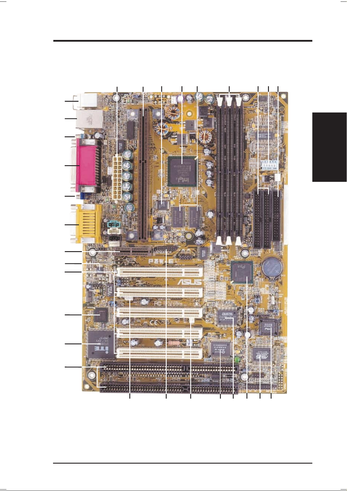
2.2 Motherboard Part Definitions
The following are part descriptions for the motherboard parts shown on the next
page.
Part Definitions
2. FEATURES
10
11
12
13
14
15
16
17
18
19
20
21
22
23
24
25
26
27
28
29
2. FEATURES
ATX Power Connector for connection to an ATX power supply
1
SEC CPU Socket
2
LCD Chipset (on LCD model only)
3
Intel 810e Integrated Graphics Chipset
4
Onboard high-speed 4MB SDRAM for integrated AGP VGA
5
Three DIMM Sockets
6
Primary and Secondary IDE Connectors
7
Feature Setting DIP Switches
8
Floppy Disk Drive Connector
9
Four Mbit Firmware Hub (programmable BIOS)
ASUS ASIC with Integrated Hardware Monitor
Intel I/O Controller Hub (ICH)
Crystal PCI Audio (on audio model only)
Low Pin Count Multi-I/O Chipset
Wake-On-Ring Connector
LCD Header for LCD connector set (LCD model only)
Wake-On-LAN Connector
Two ISA Slots (on ISA model only)
PCI to ISA Bridge (on ISA model only)
Intel 82559 Fast-Ethernet Chipset (on LAN model only)
Five or Six PCI Slots (depending on territory)
AC’97 V2.1 Compliant Audio CODEC (on audio model only)
Audio Modem Riser (AMR) Connector
Joystick, MIDI, Line Out, Line In, Microphone In Connectors (on audio
model only)
VGA Monitor Output Connector
Parallel Connector
Serial COM1 Connector
LAN (RJ45) and USB Connectors (LAN optional)
PS/2 Mouse, PS/2 Keyboard Connectors
12 ASUS P3W-E User’ s Manual
2. FEATURES
2.3 Motherboard Part Locations
2
29
28
27
3 4
7651
8 9
26
25
24
23
22
21
20
2. FEATURES
Part Locations
19
18
16
NOTE: The ISA model is shown above. ISA slots are optional at the time of pur-
chase. The model without ISA will have 6 PCI slots.
ASUS P3W-E User’s Manual 13
111415
121317
10
3. HARDWARE SETUP
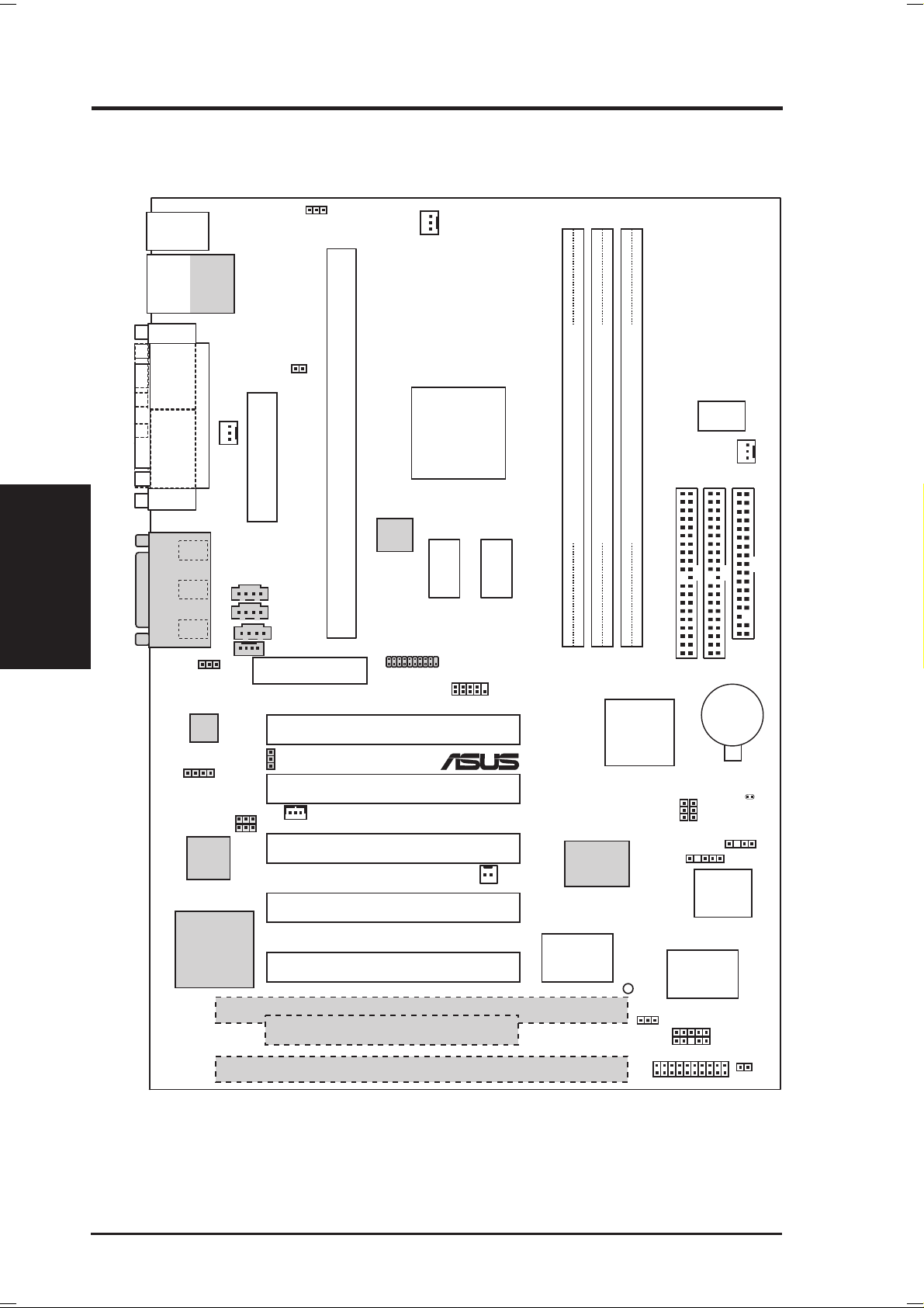
3.1 Motherboard Layout
PS/2
T: Mouse
B: Keyboard
Bottom:
USB1
USB
2
COM1
PARALLEL PORT
Motherboard Layout
3. H/W SETUP
VGA
Line
Out
Line
Mic
GAME_AUDIO
INT
MIC
SPEAKER
(SPKR)
Top:
RJ45
In
In
Audio
Codec
LAN_EN
PCI3VSEL
Intel Fast
Ethernet
JTPWR
PWR_FAN
ATX Power Connector
VIDEO
AUX
CD1
MODEM
Audio Modem Riser
(AMR)
SPK
VIO
WOL_CON
Slot1
LCD
Encoder
LCD Header
P3W-E
PCI1
PCI2
PCI3
PCI4
CPU_FAN
Intel 810e
Graphics &
Memory
Controller
Hub (GMCH)
2MB
(DFP)
SDRAM
COM2
2MB
SDRAM
WOR
01
01
01
DIP
Switches
CHA_FAN
SECONDARY
IDE
PRIMARY
IDE
DIMM1 (64/72 bit, 168-pin module)
DIMM2 (64/72 bit, 168-pin module)
DIMM3 (64/72 bit, 168-pin module)
Row
0 1
2 3
3 2
CR2032 3V
Intel I/O
Controller
®
Hub (ICH)
32-bit PCI
Audio
Chipset
Lithium Cell
CMOS Power
SAFE_MD
NO_REBOOT
CHASIS
SMB
4Mbit
Firmware
Hub
FLOPPY
CLRTC
(ACHA)
PCI to ISA
Bridge
PCI5
Multi-I/O
ISA1
PCI6
ISA2
NOTES: Grayed items are optional at the time of purchase.
The PCI/ISA configuration is dependent on territory.
14 ASUS P3W-E User’ s Manual
PLED2
JEN
ASUS
ASIC
with Hardware
Monitor
IR
PANEL
IDELED

3. HARDWARE SETUP
3.2 Layout Contents
Motherboard Settings
1) JEN p.18 JumperFree™ Mode Setting (Enable/Disable)
2) LAN_EN p.18 Onboard LAN Setting (Enable/Disable)
3) SW1 (DSW), SPK p.19 Onboard Audio Setting (Enable/Disable)
4) SAFE_MD p.20 Safe Mode Setting (Normal/Safe Mode)
5) NO_REBOOT p.20 Automatic Timeout Reboot Setting (Enable/Disable)
6) PCI3VSEL p.21 PCI 3 Volt Setting (Normal/STB)
7) VIO p.21 I/O Voltage Setting (Normal/+3.66V)
8) SW2-6 (DSW) p.22 CPU External Clock (Bus) Frequency Setting
Expansion Slots
1) DIMM1, DIMM2, DIMM3 p.25 168-Pin DIMM Memory Support
2) CPU Slot 1 p.26 Central Processing Unit (CPU) Socket
3) ISA1, ISA2 p.33 16-bit ISA Bus Expansion Slots (optional)
4) PCI1, 2, 3, 4, 5, 6 p.33 32-bit PCI Bus Expansion Slots (optional PCI6)
5) AMR p.34 Audio Modem Riser Slot
Connectors
1) PS2KBMS p.35 PS/2 Mouse Connector (6-pin female)
2) PS2KBMS p.35 PS/2 Keyboard Connector (6-pin female)
3) USB p.36 Universal Serial Bus Port Connectors (T wo 4-pin female)
4) PRINTER p.36 Parallel Port Connector (25-pin female)
5) COM1 p.36 Serial Port Connector (9-pin male)
6) VGA p.37 Monitor (VGA) Output Connector (15-pin female)
7) GAME_AUDIO p.37 Joystick/MIDI Connector (15-pin female) (optional)
8) GAME_AUDIO p.37 Audio Port Connectors (Three 1/8” female) (optional)
9) RJ45 p.37 Fast-Ethernet Port Connector (RJ45) (optional)
10) PRIMARY/SECONDARY p.38 Primary/Secondary IDE Connectors (Two 40-1 pins)
11) IDELED p.38 IDE Device Activity LED Lead (2 pins)
12) FLOPPY p.39 Floppy Drive Port Connector (34 pins)
13) CHA_, CPU_, PWR_FAN p.39 Chassis, CPU, Power Supply Fan Connectors (Three 3-pin)
3. H/W SETUP
Layout Contents
14) WOL_CON p.40 Wake-On-LAN Connector (3 pins)
15) WOR p.40 Wake-On-Ring Connector (2 pins)
16) VIDEO, AUX, CD1, MODEM p.41 Internal Audio Connectors (Four 4-pins) (optional)
17) SPKR p.41 Internal Speaker Connectors (4-pins) (optional)
18) INT MIC p.42 Internal Microphone Connector (3 pins)
19) SMB p.42 SMBus Connector (5-1 pins)
20) DFP p.43 Digital LCD Header (20-1 pins) (optional)
ASUS P3W-E User’s Manual 15

21) COM2 p.43 Serial Port Header (10-1 pin male)
22) IR p.44 Infrared Module Connectors (10-1 pins)
23) ACHA p.44 Chassis Intrusion Alarm Connector (4-1 pins)
24) KEYLOCK (PANEL) p.45 System Power LED Lead (3-1 pins)
25) KEYLOCK (PANEL) p.45 Keyboard Lock Switch Lead (2 pins)
26) SPEAKER (PANEL) p.45 System Warning Speaker Connector (4 pins)
27) RESET (PANEL) p.45 Reset Switch Lead (2 pins)
28) PWR (PANEL) p.45 ATX Power / Soft-Off Switch Lead (2 pins)
29) SMI (PANEL) p.45 System Management Interrupt Switch Lead (2 pins)
30) LED (PANEL) p.45 System Message LED (2 pins)
31) ATXPWR p.46 ATX Power Supply Connector (20 pins)
32) JTPWR p.46 Thermal Sensor Connector (2 pins)
Layout Contents
3. H/W SETUP
3. HARDWARE SETUP
16 ASUS P3W-E User’s Manual
3. HARDWARE SETUP
3.3 Hardware Setup Procedure
Before using your computer, you must complete the following steps:
• Check Motherboard Settings
• Install Memory Modules
• Install the Central Processing Unit (CPU)
• Install Expansion Cards
• Connect Ribbon Cables, Panel Wires, and Power Supply
3.4 Motherboard Settings
This section explains in detail how to change your motherboard’s function settings
through the use of switches and/or jumpers.
WARNING! Computer motherboards and expansion cards contain very delicate
Integrated Circuit (IC) chips. To protect them against damage from static electricity, you should follow some precautions whenever you work on your computer.
1. Unplug your computer when working on the inside.
2. Use a grounded wrist strap before handling computer components. If you do
not have one, touch both of your hands to a safely grounded object or to a metal
object, such as the power supply case.
3. Hold components by the edges and try not to touch the IC chips, leads or connectors, or other components.
4. Place components on a grounded antistatic pad or on the bag that came with the
component whenever the components are separated from the system.
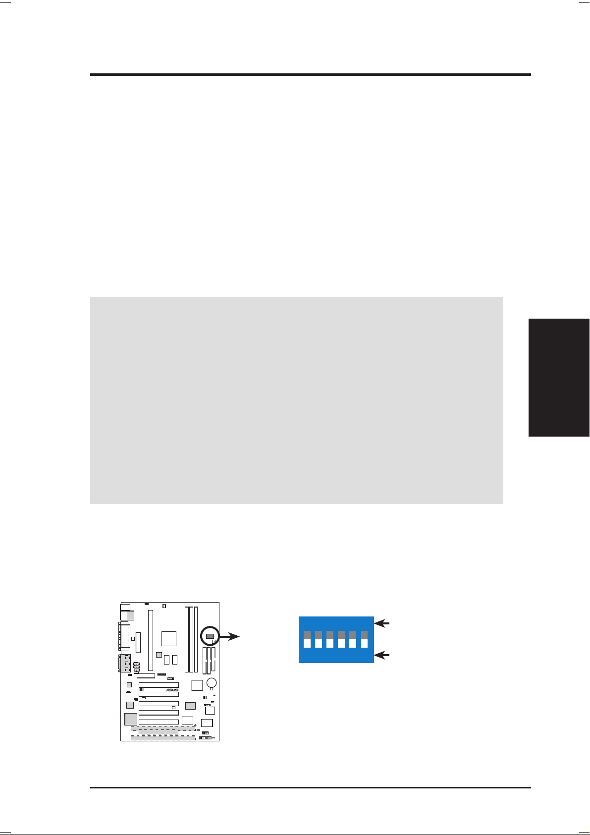
Motherboard Feature Settings (DIP Switches–DSW)
Some of the motherboard’ s onboard functions are adjusted through the DIP switches.
The white block represents the switch’s position. The example below shows all the
switches in the OFF position.
ON
DSW
ON
1010 1
3. H/W SETUP
Motherboard Settings
P3W-E
®
P3W-E DIP Switches
ASUS P3W-E User’s Manual 17
12345
1. Audio Setting
2. Frequency Selection
3. Frequency Selection
4. Frequency Selection
5. Frequency Selection
6. Frequency Selection
6
OFF
3. HARDWARE SETUP
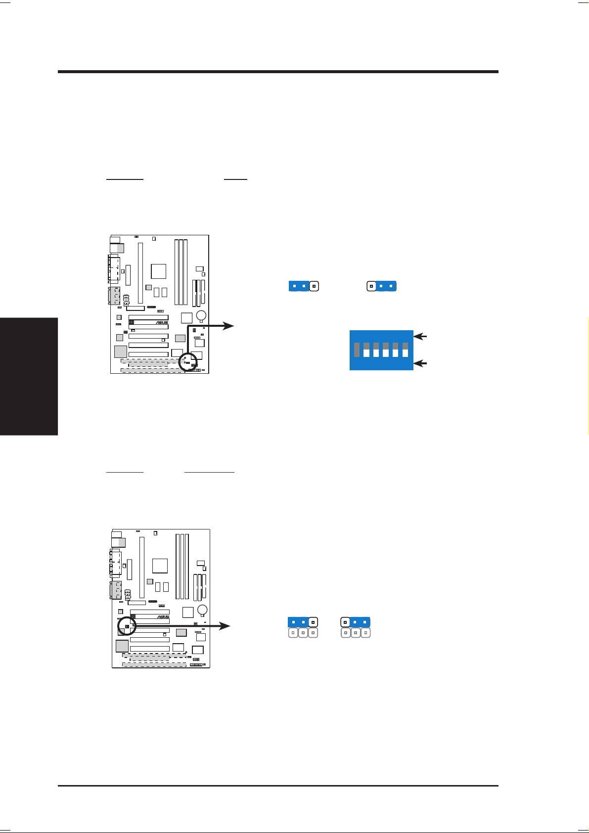
1) JumperFree™ Mode Setting (JEN)
This jumper allows you to enable or disable the JumperFree™ mode. The
JumperFree™ mode allows processor settings to be made through the BIOS
setup (see 4.4 Advanced Menu).
NOTE: For JumperFree™ mode, DIP switches 2-6 (DSW) must be set to OFF.
Setting JEN
Disable (Jumper) [1-2]
Enable (JumperFree) [2-3] (default)
1010 1
JEN
Motherboard Settings
3. H/W SETUP
P3W-E Jumper Mode Setting
2) Onboard LAN Setting (LAN_EN) available on LAN model only
The onboard LAN may be enabled or disabled by this jumper.
Setting LAN_EN
Enable [1-2] (default)
Disable [2-3]
P3W-E
123
Jumper JumperFree
®
1010 1
123
DSW
ON
1 2345
6
ON
OFF
LAN_EN
P3W-E
®
123
Enable Disable
123
P3W-E LAN Setting
18 ASUS P3W-E User’s Manual
3. HARDWARE SETUP
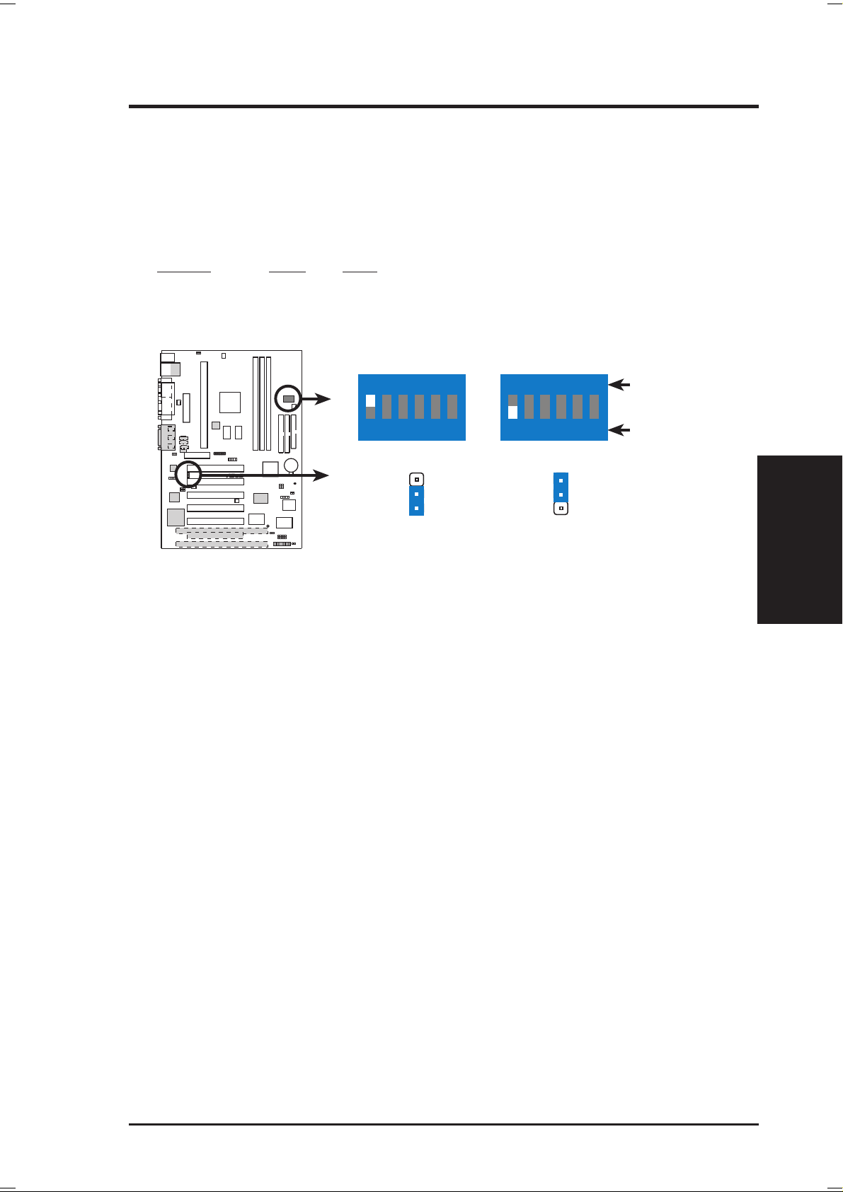
3) Onboard Audio Setting (DSW-SW1, SPK) available on audio model only
The onboard 32-bit PCI audio may be enabled by setting both the DIP switch
and jumper to Enable or disabled by setting both to Disable. Disable the onboard audio if you are using an ISA or PCI audio card on any of the expansion
slots or a primary AMR audio card on the AMR slot (see AMR Slot later in this
section).
Setting SW1 SPK
Enable [ON] [1-2] (default)
Disable [OFF] [2-3]
1010 1
P3W-E
®
P3W-E Audio Setting
DSW
ON
1 2345
SPK SPK
3
2
1
6
ON
1 2345
Enable Disable
ON
OFF
6
3
2
1
3. H/W SETUP
Motherboard Settings
ASUS P3W-E User’s Manual 19
3. HARDWARE SETUP
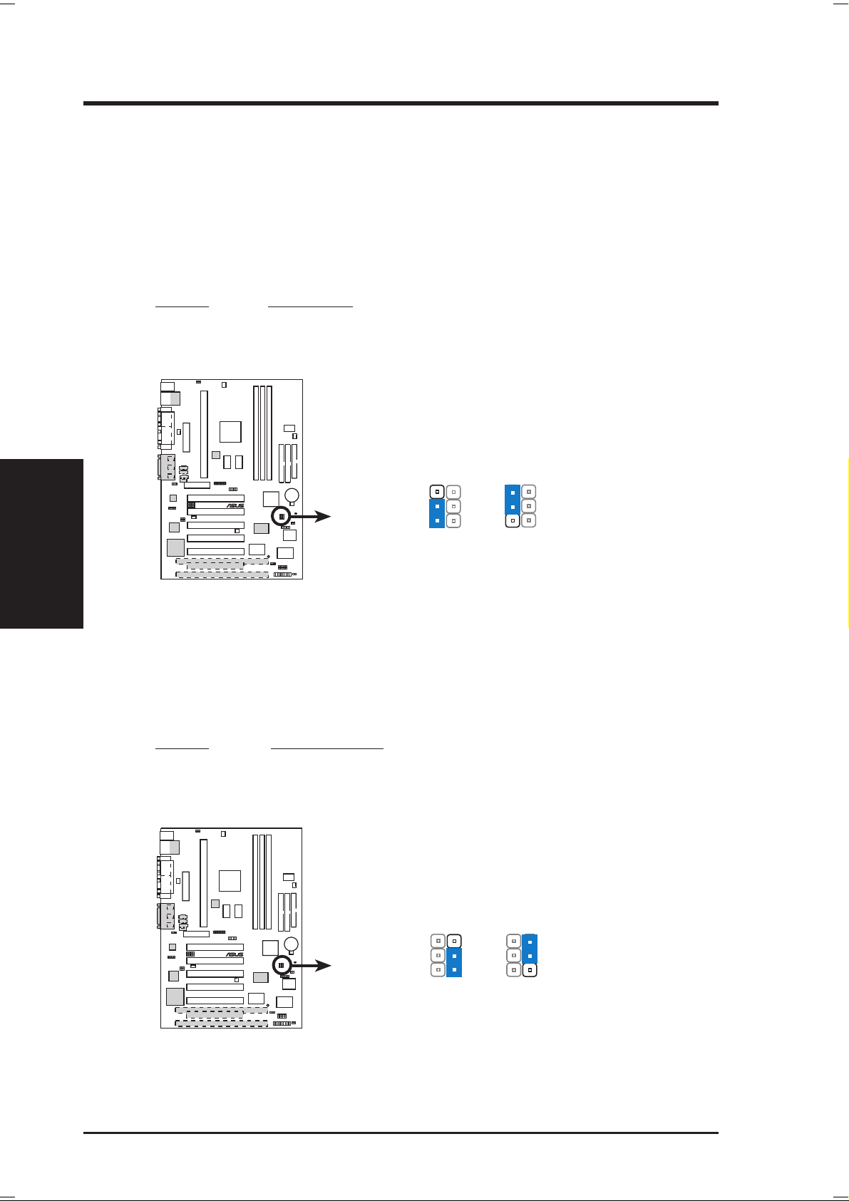
4) Safe Mode Setting (SAFE_MD)
For processors with locked frequency multiples, there is no way to exceed the
specified multiple whether through motherboard settings or BIOS setup. With
unlocked processors, exceeding the specified multiple is possible through BIOS
setup. Exceeding the specified multiple may result in hanging during bootup. If
this occurs, enable Safe Mode to force a multiple of 2 in order to enter BIOS
setup to correct the problem.
Setting SAFE_MD
Normal [1-2] (default)
Safe Mode [2-3]
1010 1
Motherboard Settings
3. H/W SETUP
P3W-E Safe Mode Setting
5) Automatic Timeout Reboot Setting (NO_REBOOT)
The motherboard is set so that when the BIOS detects a hang (timeout) during
bootup, the motherboard will automatically reboot. If rebooting is repeating ineffectively, set this jumper to No Reboot to disable auto-reboot.
Setting NO_REBOOT
Normal [1-2] (default)
No Reboot [2-3]
P3W-E
SAFE_MD
®
1010 1
3
2
1
Normal
(Default)
3
2
1
Safe Mode
NO_REBOOT
P3W-E
®
3
2
1
Normal
(Default)
3
2
1
No Reboot
P3W-E Reboot Setting
20 ASUS P3W-E User’s Manual
3. HARDWARE SETUP
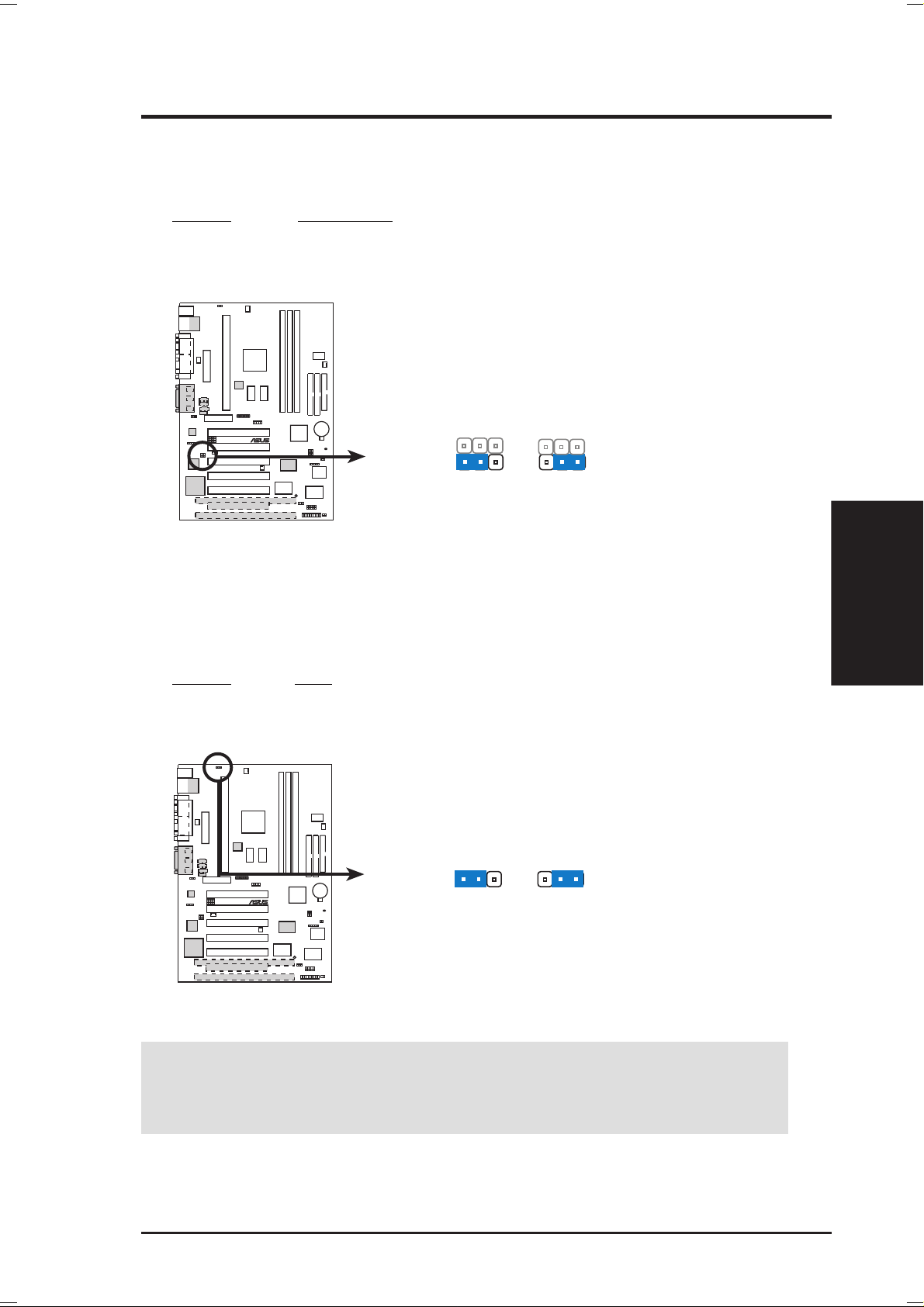
6) PCI 3 Volt Setting (PCI3VSEL)
This jumper allows you to select the voltage supplied to PCI devices. If you
have PCI devices that require auxiliary power, set this jumper to STB.
Setting PCI3VSEL
Normal [1-2]
Standby [2-3] (default)
1010 1
P3W-E
®
PCI3VSEL
123
Normal Standby
123
(STB)
P3W-E PCI 3Volt Selection
7) I/O Voltage Setting (VIO)
This jumper allows you to select the voltage supplied to the DRAM, chipset,
PCI, and the CPU’s I/O buffer. The default voltage should be used unless processor overclocking requires a higher voltage.
Setting VIO
Normal [1-2] (default)
3.66V [2-3]
1010 1
VIO
P3W-E
123
®
Normal 3.66Volt
123
3. H/W SETUP
Motherboard Settings
P3W-E I/O Voltage Setting
WARNING! Using a higher voltage may help when overclocking but may result
in the shortening of your computer component’ s life. It is strongly recommended
that you leave this setting on its default.
ASUS P3W-E User’s Manual 21
3. HARDWARE SETUP
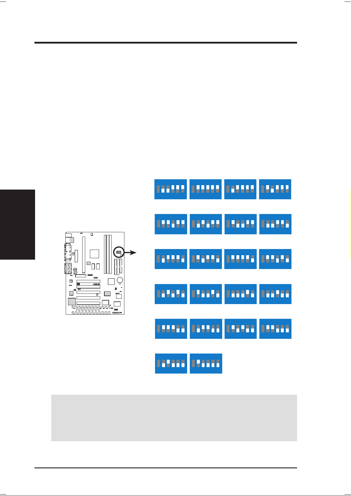
8) CPU External Frequency Setting (DSW–SW2-6)
This option tells the clock generator what frequency to send to the CPU, DRAM,
and the PCI bus. This allows the selection of the CPU’ s External frequency . The
CPU External Frequency multiplied by the Frequency Multiple equals the CPU’ s
Internal frequency (the advertised CPU speed). NOTE: You may set the memory
speed independently from the CPU External Frequency. Depending on your
memory type, select the appropriate “SDRAM” speed along with the appropriate “CPU” speed.
IMPORTANT: When JumperFree mode is enabled, use BIOS setup in place of
these switches (see CPU Speed in 4.4 Advanced Menu). Only selected switches
are illustrated, see the next page for a complete frequency listing.
NOTE: For JumperFree mode, DIP switches 2-6 (DSW) must be set to OFF.
Motherboard Settings
3. H/W SETUP
P3W-E CPU External Clock
(BUS) Frequency Selection
P3W-E
CPU
CPU
CPU
CPU
CPU
ON
1 2345
→
66MHz
→
100MHz
ON
1 2345
→
72MHz
→
108MHz
ON
1 2345
→
104MHz
→
104MHz
ON
1 2345
→
123MHz
→
123MHz
ON
1 2345
→
136MHz
→
102MHz
ON
DSW
SDRAM
1010 1
®
SDRAM
SDRAM
SDRAM
SDRAM
6
6
6
6
6
ON
1 2345
69MHz
103MHz
ON
1 2345
75MHz
112MHz
ON
1 2345
109MHz
109MHz
ON
1 2345
133MHz
133MHz
ON
1 2345
140MHz
105MHz
ON
6
6
6
6
6
ON
1 2345
70MHz
105MHz
ON
1 2345
76MHz
114MHz
ON
1 2345
111MHz
111MHz
ON
1 2345
142MHz
142MHz
ON
1 2345
143MHz
107MHz
ON
6
1 2345
6
ON
6
1 2345
6
6
71MHz
106MHz
ON
1 2345
100MHz
100MHz
117MHz
117MHz
ON
1 2345
133MHz
100MHz
ON
1 2345
146MHz
110MHz
6
6
6
6
6
CPU
SDRAM
1 2345
→
149MHz
→
112MHz
6
1 2345
153MHz
115MHz
6
WARNING! CPU frequencies other than 66MHz, 100MHz, and 133MHz are
not guaranteed to be stable. Premature wearing of the processor may result when
overclocking. Be sure that the DIMM you use can handle the specified SDRAM
MHz or else bootup will not be possible.
22 ASUS P3W-E User’s Manual

3. HARDWARE SETUP
External Frequency Table
The following table is for use by experienced motherboard installers only . Overclocking can result in system instability or even shortening the life of the processor .
CPU SDRAM PCI Frequency Selection Switches
(MHz) (MHz) (MHz) 23456
69.00 103.50 34.50 [ON] [ON] [ON] [ON] [ON]
70.00 105.00 35.00 [OFF] [ON] [ON] [ON] [ON]
71.00 106.50 35.50 [ON] [OFF] [ON] [ON] [ON]
66.82 100.23 33.41 [OFF] [OFF] [ON] [ON] [ON]
72.00 108.00 36.00 [ON] [ON] [OFF] [ON] [ON]
75.00 112.50 37.50 [OFF] [ON] [OFF] [ON] [ON]
76.60 114.90 38.40 [ON] [OFF] [OFF] [ON] [ON]
111.77 111.77 37.26 [ON] [ON] [ON] [ON] [OFF]
104.78 104.78 34.93 [OFF] [ON] [ON] [ON] [OFF]
109.51 109.51 36.50 [ON] [OFF] [ON] [ON] [OFF]
100.74 100.74 33.57 [OFF] [OFF] [ON] [ON] [OFF]
117.00 117.00 39.00 [ON] [ON] [OFF] [ON] [OFF]
123.75 123.75 41.25 [OFF] [ON] [OFF] [ON] [OFF]
133.33 133.33 44.44 [ON] [OFF] [OFF] [ON] [OFF]
142.50 142.50 47.50 [OFF] [OFF] [OFF] [ON] [OFF]
136.00 102.25 34.25 [ON] [ON] [ON] [OFF] [OFF]
140.00 105.00 70.00 [OFF] [ON] [ON] [OFF] [OFF]
143.00 107.50 36.00 [ON] [OFF] [ON] [OFF] [OFF]
133.90 100.68 33.73 [OFF] [OFF] [ON] [OFF] [OFF]
146.67 110.00 36.67 [ON] [ON] [OFF] [OFF] [OFF]
149.33 112.00 37.33 [OFF] [ON] [OFF] [OFF] [OFF]
153.30 115.29 38.60 [ON] [OFF] [OFF] [OFF] [OFF]
3. H/W SETUP
Motherboard Settings
NOTE: The PCI clock is equal to 1/3 the speed of the SDRAM. PCI’s specification
allows for up to 33MHz, therefore using PC100-compliant DIMM and setting
SDRAM to about 100MHz is recommended. For updated processor settings, visit
ASUS’s web site (see ASUS CONTACT INFORMATION).
ASUS P3W-E User’s Manual 23
3.5 System Memory (DIMM)
NOTE: No hardware or BIOS setup is required after adding or removing memory.
This motherboard uses only Dual Inline Memory Modules (DIMMs). Sockets are
available for 3.3Volt (power level) unbuffered Synchronous Dynamic Random Ac-
cess Memory (SDRAM) of 16, 32, 64, 128MB, or 256MB.
This chipset does not support ECC. However, ECC memory modules may still be
used, but the ECC function will not be available.
Memory speed setup is recommended through SDRAM Configuration in 4.4.1
Chip Configuration.
Install memory in any combination as follows:
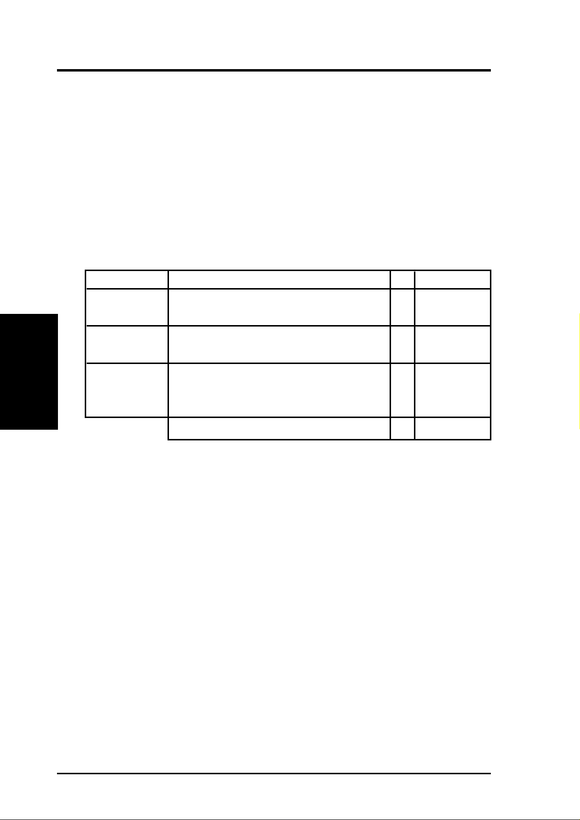
Location 168-pin DIMM SDRAM Total Memory
DIMM1 Single-Sided
System Memory
3. H/W SETUP
(Rows 0&1) Double-Sided x1
DIMM2 Single-Sided (must be occupied before DIMM3)
(Rows 2&3) Double-Sided (DIMM3 must be empty) x1
3. HARDWARE SETUP
DIMM3 Single-Sided (DIMM2 must be single-sided)
(Rows 3&2) (Double-Sided DIMM cannot be used here!) x1
(must be same or half DIMM2 memory size)
Total System Memory (Max 512MB) =
3.5.1 General DIMM Notes
• ASUS motherboards support SPD (Serial Presence Detect) DIMMs. This is the
memory of choice for best performance vs. stability.
• SDRAM chips are generally thinner with higher pin density than EDO (Extended Data Output) chips.
• BIOS shows SDRAM memory on bootup screen.
• Single-sided DIMMs come in 16, 32, 64,128MB; double-sided come in 32, 64,
128, 256MB.
24 ASUS P3W-E User’s Manual
3. HARDWARE SETUP
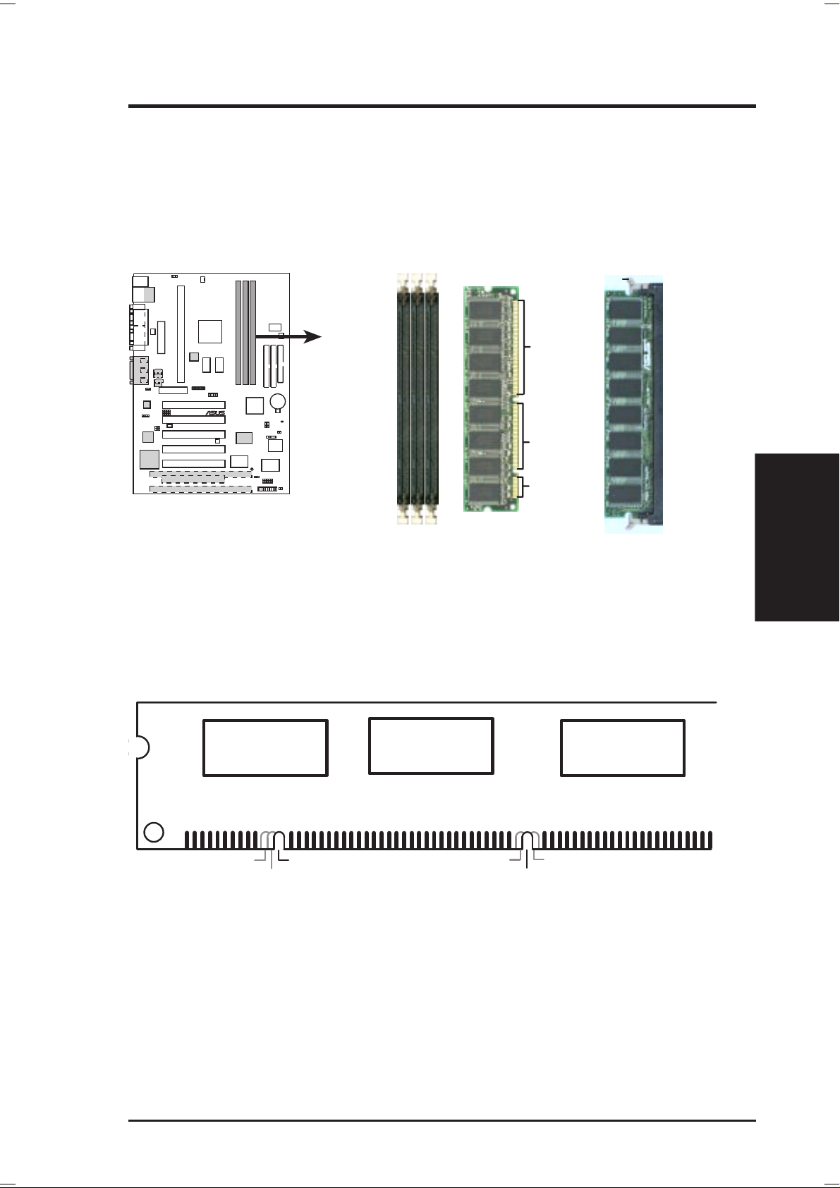
3.5.2 DIMM Installation
Insert the module(s) as shown. Because the number of pins are different on either
side of the breaks, the module will only fit in the orientation shown. DIMMs are
longer and have different pin contact on each side and therefore have a higher pin
density. SIMMs have the same pin contact on both sides.
10 101
88 Pins
P3W-E
®
60 Pins
20 Pins
Lock
FRONT
P3W-E 168-Pin DIMM Sockets
The DIMMs must be 3.3V Unbuffered for this motherboard. T o determine the DIMM
type, check the notches on the DIMMs (see figure below).
3. H/W SETUP
System Memory
168-Pin DIMM Notch Key Definitions (3.3V)
DRAM Key Position
RFU
Buffered
Unbuffered
Voltage Key Position
5.0V
Reserved
3.3V
The notches on the DIMM module will shift between left, center , or right to identify
the type and also to prevent the wrong type from being inserted into the DIMM slot
on the motherboard. You must ask your retailer the correct DIMM type before purchasing. This motherboard supports four clock signals per DIMM slot.
ASUS P3W-E User’s Manual 25
3.6 Central Processing Unit (CPU)
NOTE: The following pictures are provided for reference purposes only. The appearance of your retention mechanism and fan may be different from the following
examples.
Your motherboard provides a Slot 1 connector for a Pentium
aged in a Single Edge Contact Cartridge (SECC2), a Pentium® II processor packaged in SECC2/SECC, or a Celeron™ processor packaged in a Single Edge Processor Package (SEPP). An ASUS S370 CPU card can allow Socket 370 processors to
be used on any ASUS motherboard with the Slot 1 connector (See 7.2 S370 Series
CPU Card for instructions on using this card).
3. H/W SETUP
3. HARDWARE SETUP
®
III processor pack-
CPU
Pentium II processor packaged in an SECC with
heatsink and fan (top view)
Pentium III (in an SECC2) with heatsink and fan
NOTE: The SEPP fan (for Celeron processors) is
similar to SECC2 fan except that the clamping
design is different.
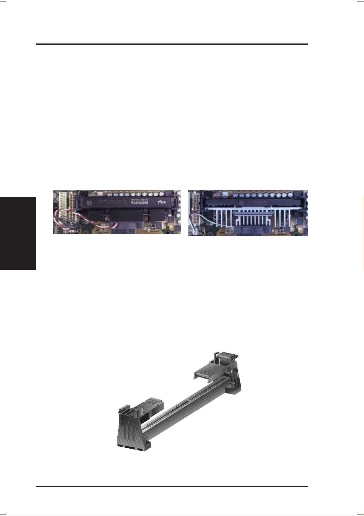
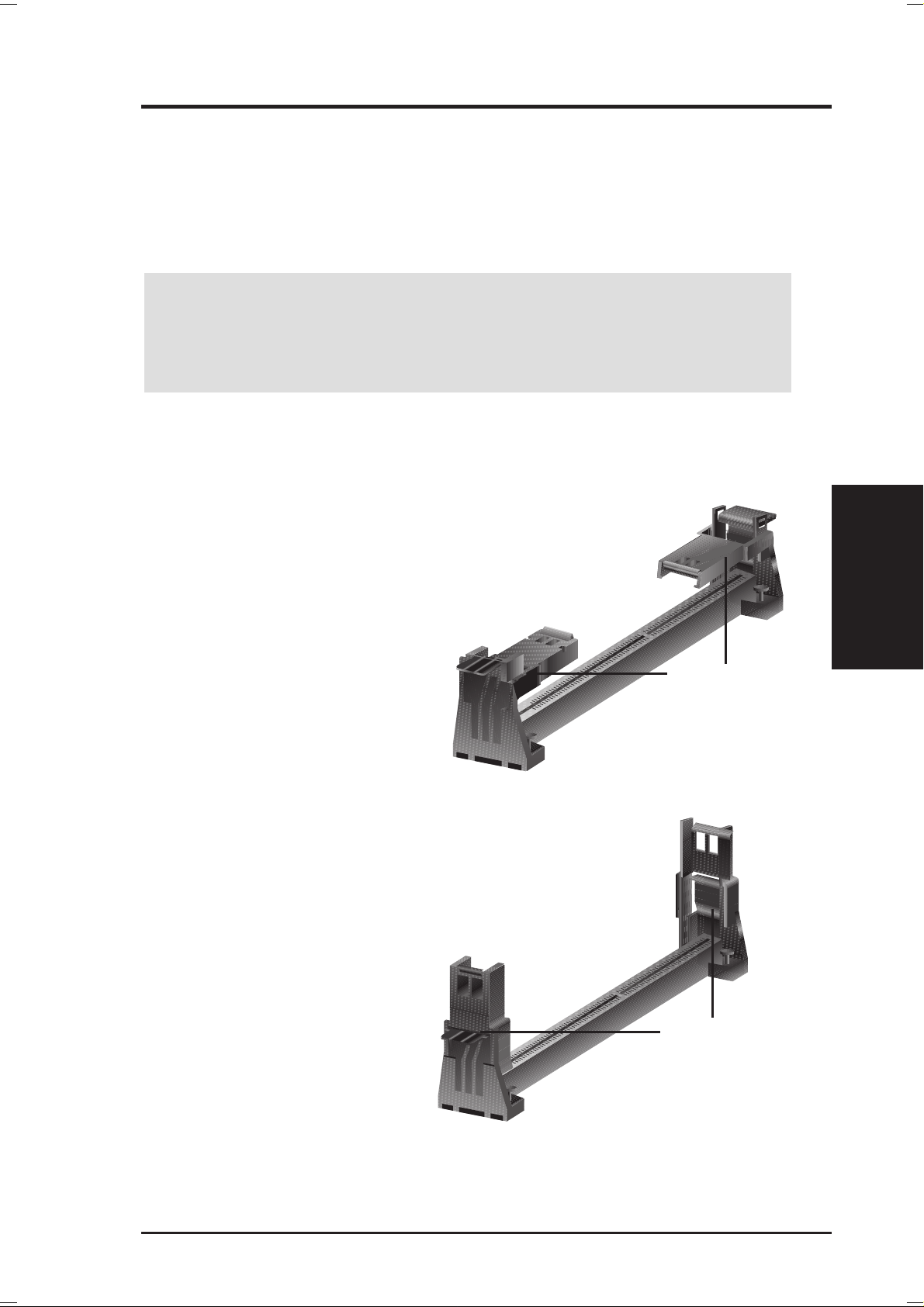
3.6.1 Universal Retention Mechanism
Y our motherboard comes preinstalled with a Universal Retention Mechanism (URM).
The URM supports Pentium III / II and Celeron processors.
Universal Retention Mechanism (URM)
26 ASUS P3W-E User’s Manual
3. HARDWARE SETUP
3.6.2 Heatsinks
The recommended heatsinks (see section on recommended heatsinks for Pentium
III / II processors for more information) for the boxed Pentium III / II and Celeron
processors are those with three-pin fans that can be connected to the fan connectors
on the motherboard.
WARNING! Be sure that there is sufficient air circulation across the processor’s
heatsink by regularly checking that your CPU fan is working. W ithout sufficient
circulation, the processor could overheat and damage both the processor and the
motherboard. You may install an auxiliary chassis fan, if necessary.
3.6.3 Installing the Processor
1. Unlock the URM’s Folding Support
Arms: The folding support arms of
the URM are locked when shipped.
T o unlock the support arms, simply flip
them up to an upright position.
CPU
3. H/W SETUP
Locked Folding Support
Unlocked Folding Support
The URM is now ready for the installation of your processor.
ASUS P3W-E User’s Manual 27
3. HARDWARE SETUP
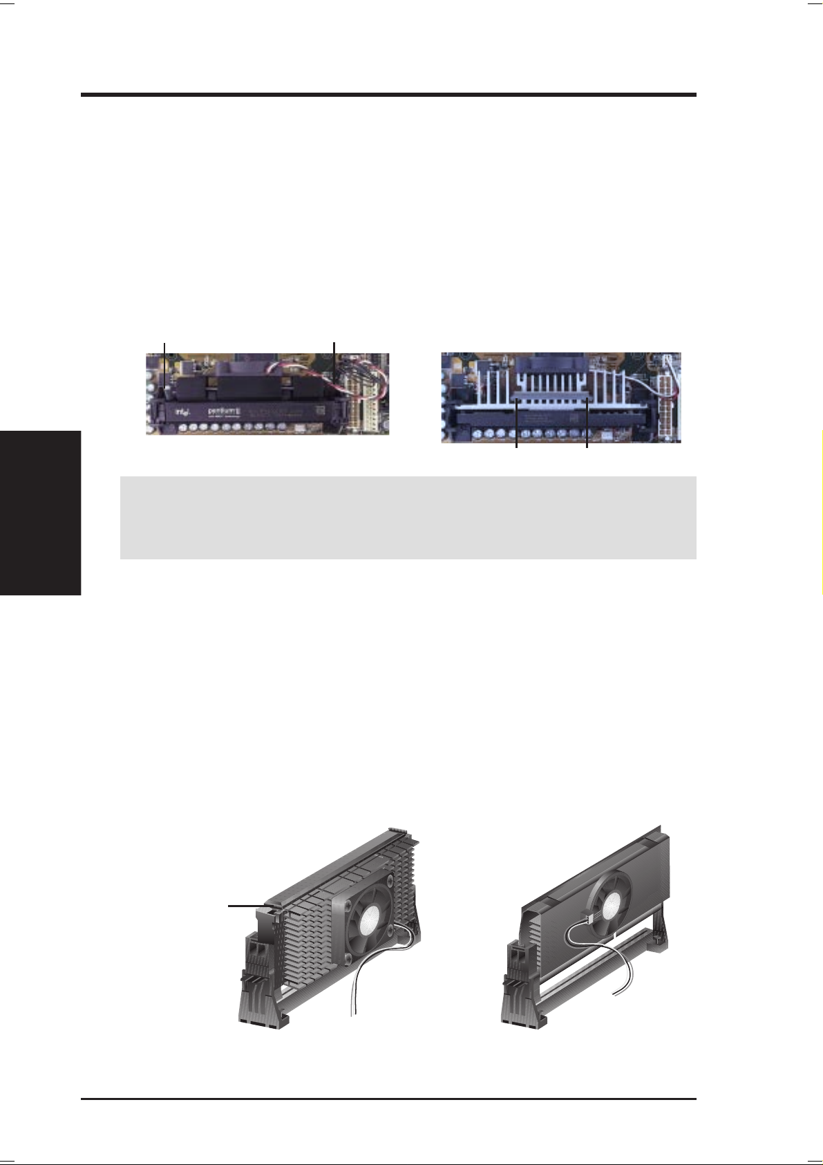
2. Attach the Heatsink
NOTE: If provided, you should follow the heatsink attachment instructions
that came with your heatsink or processor. The following steps are provided
only as a general guide and may not reflect those for your heatsink.
3. H/W SETUP
CPU
®
Using SECC fan with Pentium
Push the two lock arms one direction to
clamp the heatsink onto the processor
and the other direction to release.
Lock Arm
Lock Arm
II
Using SECC2 fan with Pentium
Insert the four heatsink’s pins through
the holes of the SECC2. Place the metal
clip on the ends of the pins and slide
until it locks into place.
Four Pins and metal clip
®
III
W ARNING! Make sure the heatsink is mounted tightly against the SECC2, SECC,
or SEPP; otherwise, the CPU will overheat. You may install an auxiliary fan to
provide adequate circulation across the processor’s passive heatsink.
NOTE: The SEPP heatsink and fan (for Intel Celeron processors) is similar to
the SECC2 heatsink and fan except that the clamping design is different.
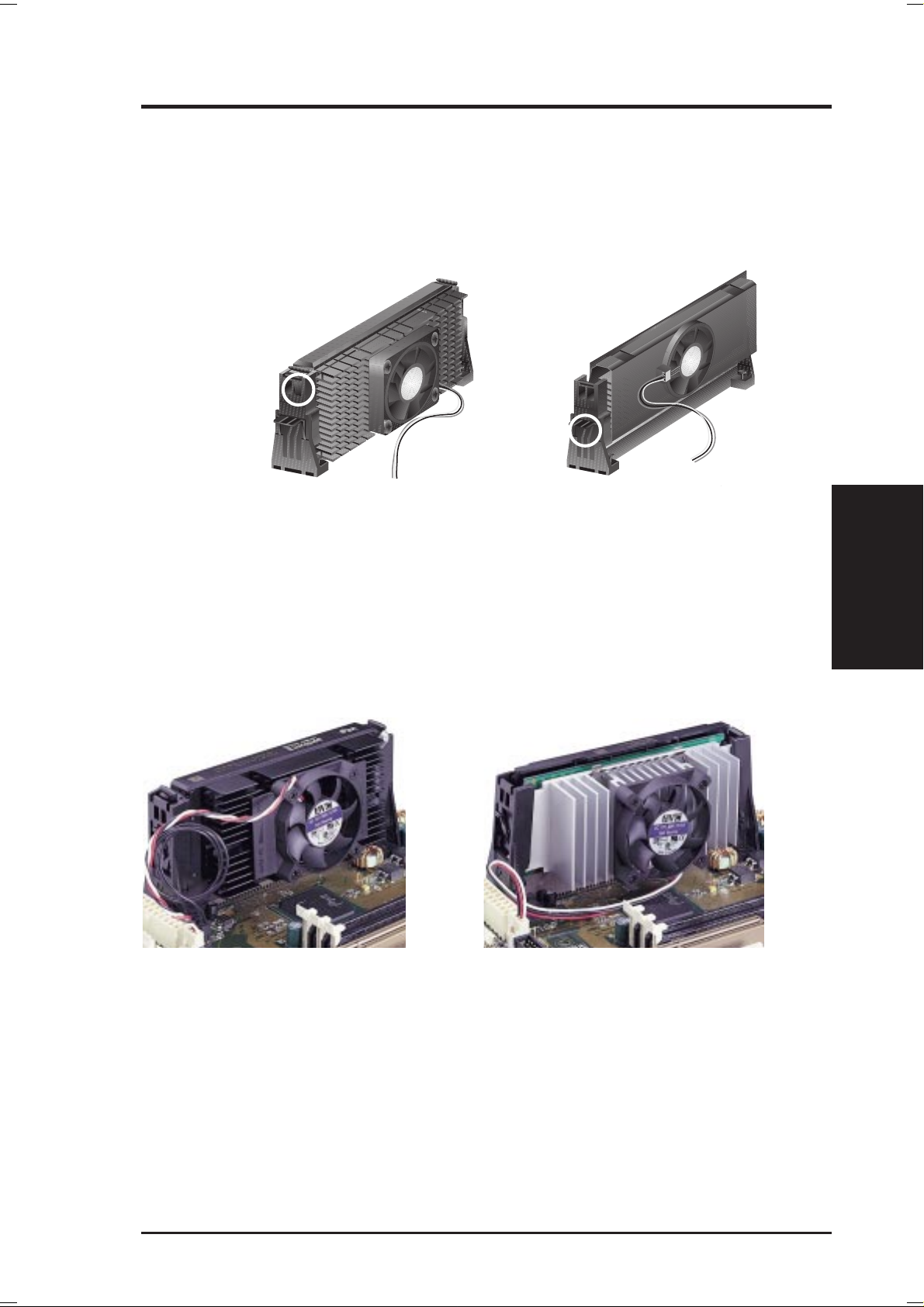
3. Insert the SECC2/SECC/SEPP
®
SECC with Pentium
II only: Push the SECC’s two locks inward until you hear
a click (the picture in step 2 shows the locks in the outward position and inward in
the picture below).
With the heatsink facing the motherboard’s chipset, push the SECC2, SECC, or
SEPP gently but firmly into the Slot 1 connector until it is fully inserted.
SECC
Push lock inward
CPU fan cable to
fan connector
SECC2/SEPP
CPU fan cable to
fan connector
28 ASUS P3W-E User’s Manual
3. HARDWARE SETUP
4. Secure the SECC2/SECC/SEPP
Secure the SECC2/SECC/SEPP in place by pushing the SECC2/SECC/SEPP
until it is firmly seated on the Slot 1 connector.
®
SECC with Pentium
cured so that the lock shows through the retention mechanism’s lock holes.
SECC SECC2/SEPP
Lock hole
II only: The SECC locks should be outward when se-
Lock hole
CPU fan cable to
fan connector
CPU fan
cable to fan
connector
3.6.4 Recommended Heatsinks for Slot 1 Processors
The recommended heatsinks for the Slot 1 processors are those with three-pin fans,
such as the ASUS Smart Fan, that can be connected to the motherboard’s CPU fan
connector . These heatsinks dissipate heat more efficiently and with an optional hardware monitor, they can monitor the fan’s RPM and use the alert function with the
Intel LANDesk Client Manager (LDCM) or the ASUS PC Probe software.
CPU
3. H/W SETUP
SECC Heatsink & Fan SECC2 Heatsink & Fan
NOTE: The SEPP heatsink and fan (for Intel Celeron processors) is similar to the
SECC2 heatsink and fan except that the clamping design is different.
ASUS P3W-E User’s Manual 29
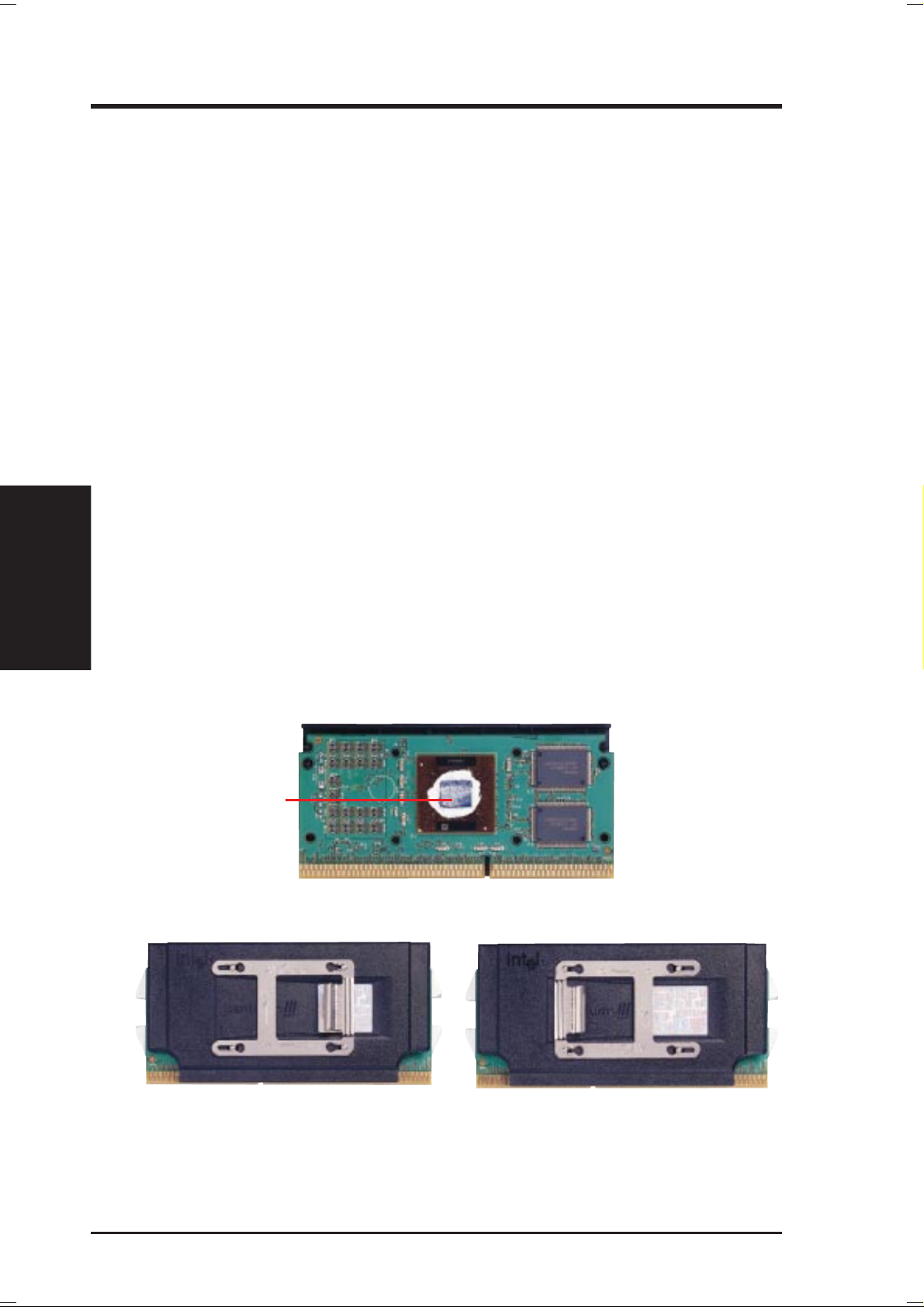
3.6.5 Precautions
Operating a processor at temperatures above its maximum specified operating temperature will shorten the processor lifetime and may cause unreliable operation. To
prevent system overheat and/or damage, it is important to have accurate temperature readings of the processor core (the main source of power dissipation) for system thermal management. Included inside Pentium III, Pentium II (Deschutes), and
PPGA370 Celeron processors is a thermal sensor that is connected to the internal
thermal diode.
Unlike other motherboards, this motherboard was designed to acquire thermal data
directly from the processor thermal diode. Therefore, the CPU temperature reported
may be higher than those from motherboards that take readings from thermal sensors external to the processor. This is not a cause for alarm. If, however, the BIOS
and/or your hardware monitoring program is reporting a CPU temperature above
the threshold, check the following:
3. H/W SETUP
3. HARDWARE SETUP
CPU
1. An Intel recommended fan heatsink is used.
2. Good quality thermal interface material is used.
3. The heatsink is correctly installed onto the processor with a strong retention clip.
4. There is no visible gap between the processor die and heatsink.
The thermal interface material
should be continuous with no
through-holes or debris.
Example of a correctly installed retention clip
Example of an incorrectly installed retention clip
30 ASUS P3W-E User’s Manual
 Loading...