

Page 1

Notebook PC
Software Reference
Product Name: Notebook PC Support CD
Manual Revision: 1.00 E992
Release Date: May 2002
1
Page 2

Software Reference
Support CD for Windows............................................................................. 5
Table of Contents
Drivers for Windows ................................................................................................................ 5
ATI Mobility Radeon VGA Driver..................................................................8
Display Settings for Windows XP.......................................................................................... 10
Display Properties............................................................................................................ 10
Intel Application Accelerator..................................................................... 14
Overview .......................................................................................................................... 14
Operating Systems not supported ...................................................................................14
General Features ............................................................................................................. 14
Component Overview ......................................................................................................14
Overview .......................................................................................................................... 16
Operating Systems not supported ...................................................................................16
General Features ............................................................................................................. 17
Component Overview: Intel® Application Accelerator Driver .......................................... 18
Component Overview: Displaying Controller and Device Information ............................ 18
Controller Parameters:..................................................................................................... 18
Device Parameters: .........................................................................................................18
Synaptics TouchPad .................................................................................. 19
Overview of Synaptics® TouchPad Features........................................................................ 20
Tap on the Pad Instead of Pressing the Buttons.............................................................. 20
Drag Icons, Windows and Other Objects without Using Buttons ..................................... 20
Adjust the Overall Touch Sensitivity................................................................................. 21
Customize Buttons and Taps ........................................................................................... 21
Prevent Accidental Pointing While Typing........................................................................ 22
Scroll Through A Document without Using Scroll Bars .................................................... 22
Zoom In/Out and Pan on Documents ..............................................................................22
Move the Pointer Long Distances .................................................................................... 23
Fine Tune the Pointer Movement..................................................................................... 23
Accessories...................................................................................................................... 23
More About the TouchPad................................................................................................ 23
Property Pages ..................................................................................................................... 23
Scrolling Properties Page ................................................................................................24
2
Page 3

Tap Zones Properties Pages............................................................................................ 25
More Features Properties Page....................................................................................... 26
Button Actions Properties Page ....................................................................................... 27
Touch Properties Page..................................................................................................... 28
Edge Motion Properties Page .......................................................................................... 29
Frequently Asked Questions ................................................................................................. 30
PC-cillin 2000.............................................................................................. 33
Welcome to PC-cillin ............................................................................................................. 34
What’s New in PC-cillin 2000........................................................................................... 35
What is a Computer Virus? .............................................................................................. 36
Test Virus ......................................................................................................................... 36
How Viruses Spread ........................................................................................................ 37
Virus Writers..................................................................................................................... 37
PC-cillin 2000 Screens..........................................................................................................38
Hotkey Utility .............................................................................................. 39
Hotkey Utility ......................................................................................................................... 40
Buttons............................................................................................................................. 40
Hotkey Actions ................................................................................................................. 41
Adding a Program to Run ................................................................................................ 44
Software Reference
Windows Flash Utility (WINFLASH).......................................................... 45
Updating Your BIOS ......................................................................................................... 46
Resetting Your BIOS ........................................................................................................ 47
ASUS PC Probe .......................................................................................... 49
Welcome to ASUS PC Probe ................................................................................................ 50
Starting ASUS PC Probe ................................................................................................. 50
Using ASUS PC Probe Monitoring................................................................................... 51
ASUS PC Probe Taskbar Icon ......................................................................................... 52
Power4 Gear ............................................................................................... 53
Benefits of Power4 Gear.................................................................................................. 54
Power4 Gear Interface..................................................................................................... 54
Power4 Gear Modes ........................................................................................................ 55
Power4 Gear Configuration ............................................................................................. 56
3
Page 4

Software Reference
Check Mail Utility ....................................................................................... 59
Check Mail Quick Setup........................................................................................................ 60
Check Mail Startup........................................................................................................... 60
Using Windows Start Menu.............................................................................................. 60
Using MS Configuration ................................................................................................... 60
LAN Settings............................................................................................... 60
Joining a Domain or Workgroup (Windows XP)............................................................... 63
Viewing Your Network ...................................................................................................... 64
Configuring the BIOS................................................................................. 65
BIOS Setup Program ............................................................................................................ 66
Updating your BIOS ..............................................................................................................66
BIOS Menu Bar................................................................................................................ 67
BIOS Legend Bar............................................................................................................. 67
Main Menu ............................................................................................................................ 69
Primary Master (sub-menu) .................................................................................................. 71
Secondary Master (sub-menus)............................................................................................ 74
Advanced Menu .................................................................................................................... 75
I/O Device Configuration (sub-menu).................................................................................... 76
Security Menu ....................................................................................................................... 78
Power Menu .......................................................................................................................... 80
Boot Menu............................................................................................................................. 81
Exit Menu .............................................................................................................................. 82
4
Page 5

Support CD for Windows
The Notebook PC you purchased may or may not be preloaded with an operating system. The support CD
included with this Notebook PC provides all the necessary drivers and utilities in order for you to use your
Notebook PC with Microsoft® Windows® XP (referred to as “Windows” in this User’s Manual).
The levels of hardware and software support may vary depending on the installed operating system. Operat-
ing systems not pre-installed on this Notebook PC may produce different results than the ones described in
the provided user’s manuals.
If your Notebook PC is not preloaded with any operating system, or you want to install another operating
system other than the preloaded one, the following pages will give step-by-step installation procedures for
typical system configurations under the Windows
online help provided with each of the applications after installation. The following are contents of a typical
support CD. Variations may be found for each territory or language. If the autorun menu does not appear,
double clicking the CD-ROM disc drive icon in “My Computer” (may be the (D:) drive or (E:) drive on hard
drives with two partitions) or running SETUP.EXE (through Start menu “Run...”) located in the root of the
support CD, will bring up the autorun menu.
®
operating system. For application usage, please see the
Drivers for Windows
The following are descriptions of each autorun menu item. Due to ongoing improvements in the support CD,
there may be some differences between this User’s Manual and your support CD. The names in quotations
are the actual driver names displayed in the System Properties of MS Windows. Windows cannot contain all
the device drivers from every manufacturer, with every update; therefore the provided support CD will
contain the best driver for your built-in devices and should be used in place of any Windows default drivers.
Intel 845M INF Update (required) “Intel 828XX” Drivers
Software Reference
Shown under Windows “System devices.” This installs drivers for the Notebook PC’s specific chipset.
ATKACPI Driver (required) “ATK0100 ACPI UTILITY” Driver
Shown under Windows “System devices.” This installs drivers for the Notebook PC’ s Advanced Configura-
tion and Power Interface (ACPI) for features utilizing power management functions.
VGA Driver (required) “ATI Mobility Radeon M7” Driver
Shown under Windows “Display adapters.” This installs display drivers for your operating system in order
to properly use the Notebook PC’s built-in graphics controller and to provide optimal features. Once the
display driver is installed, you can change your display’s resolution and color through Display Properties.
Audio Driver (required) “Crystal WDM Audio Codec” Driver
Shown under Windows “Sound, video and game contr ollers.” This installs audio drivers for your operating
system in order to properly use the Notebook PC’s built-in sound controller . All audio functions are configured
through Windows and help can be located within Windows documentation or Windows help files.
5
Page 6

Software Reference
IAA Utility (optional) Utility
The Intel® Application Accelerator is a software package designed specifically to increase the performance
of applications and computer systems running Intel® Pentium® III or Pentium® 4 Processor.
Modem Driver (required-WinME) “HSP56 MR” Driver
Installs the necessary driver in order for your operating system to have the correct files for the Notebook PC
with built-in modem and drivers for integration with the internal audio. With third-party software, fax and
speaker phone capabilities are possible using this Notebook PC.
TouchPad (recommended) “Synaptics PS/2 TouchPad” Driver
Shown under Windows “Mice and other pointing devices.” Installs “Synaptics® TouchPad” utility. The
Notebook PC already supports built-in or externally connected keyboard and PS/2 mouse devices. However,
the provided device driver will provide enhancements and features to the T ouchPad to increase the functionality of the TouchPad. For detailed information, see the Software Reference in the next section. To access
help, right-click the TouchPad icon on the taskbar and select Help.
Fast IR Driver (required) “IrDA Fast Infrared Port” Driver
Shown under “Network adapters”. Installs driver and configures your Infrared Transceiver A to “HP HSDL2300/3600” so that your Infrared port can work properly .
PC-cillin 2000 (optional) Utility
Installs T r end’s PC-cillin 2000, a world-class anti-virus protection software for the new Internet era, to keep
your PC virus-free. This very powerful anti-virus software is bundled with each Notebook PC to protect your
investment. As software become more and more a part of our daily lives, measures have to be taken to
protect them. You may skip this software if you have your own anti-virus software.
ATKACPI Utility (submenu) Link
Shows you a sub-menu with additional utilities. These utilities require that you first install the ATKACPI
driver. See next page for descriptions of the utilities.
LAN Driver (required) “Realtek RTL8139/810X Family PCI Fast Ethernet NIC” Driver
Located under Windows “Network Adapters.” Installs the required LAN driver for the Notebook PC’s
built-in PCI Fast-Ethernet controller. Fast-Ethernet supports both 10 Base-T or 100 Base-TX networks at
half or full duplex.
Read Me Text
Gives you notes concerning this support CD or the Notebook PC.
Browse this CD
Shows you the contents of this support CD using W indows Explorer.
6
Page 7

Technical Support Form Text
Opens up a T echnical Support Request Form so that you will understand what kind of information is needed
if you run into problems and require technical assistance.
Exit
Closes the support CD autorun screen.
ATKACPI Utility (Submenu)
Hotkey Utility (required) Utility
Installs Hotkey utility. Hotkey utility is a program designed to intercept key strokes so that key assignments
can be made to run a program or script. This program cannot be used to change default keys or key combi-
nations used by other software, operating systems, or by the Notebook PC’s hardware.
Windows Flash Utility (recommended) Utility
Installs a BIOS update utility for Windows so that you can conveniently update your Notebook PC’s BIOS
without having to restart your Notebook PC in DOS mode.
ASUS PC Probe (optional) Utility
Installs PC Probe utility to monitor the Notebook PC’s CPU temperature and other resources. This is an
optional software to help you better manage your Notebook PC’s resources.
Power4 Gear Utility (optional) Utility
Power4 Gear is a custom utility designed for this Notebook PC that allows you to use predefined or user
defined values for multi-selectable power saving modes or “gears”. You can “shift” between the “gears”
using the taskbar icon or the “Power Gear” key above the keyboard.
Software Reference
Check Mail Utility (optional) Utility
Installs Check Mail Utility to monitor and notify you of incoming email messages waiting in your Mi-
crosoft® Outlook or Outlook Express Inbox. (This utility may or may not be compatible with other email
applications.)
7
Page 8

8
Page 9

ATI Mobility Radeon VGA Driver
Topics Covered:
Display Properties and Settings
Software Reference
Screens will vary depending on your operating system but the contents should be the same.
9
Page 10
Software Reference
Display Settings for Windows XP
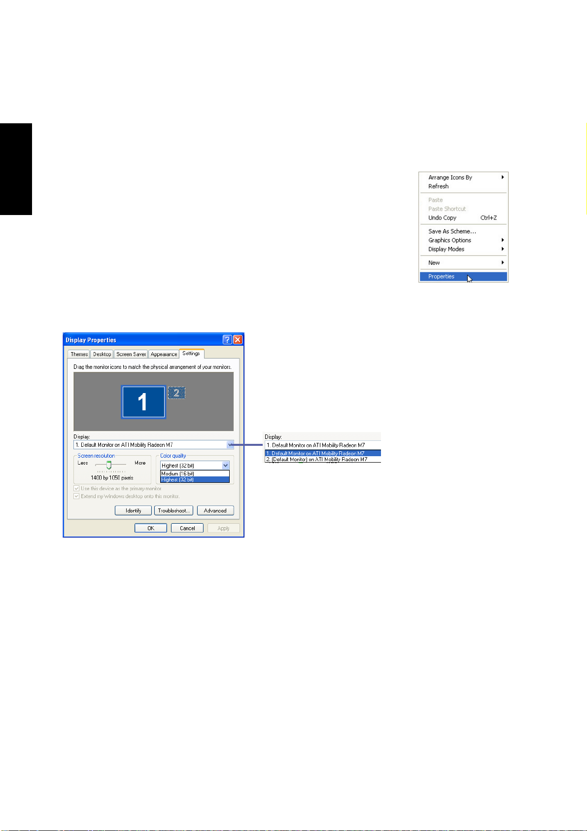
Display Properties
By right clicking your desktop and selecting Properties, you can view your display properties. For advanced graphics controller settings, click the Advanced
button.
Using Windows Display Properties
Dual View Funtion
If you connect an external display, you can select Display 2
and extend your desktop onto the second display .
10
You can set each display independently by choosing
monitor 1 or 2 here.
Page 11
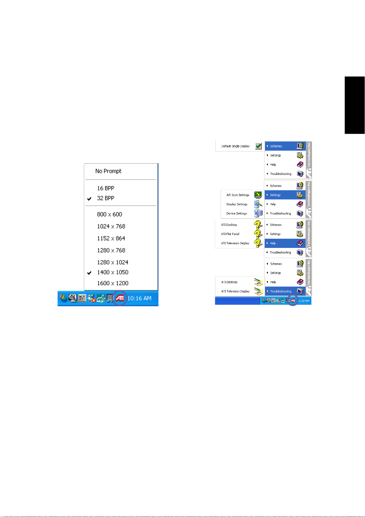
Using the Taskbar Icon
Left-click the ATI icon on the taskbar to bring
up shortcuts to screen resolution settings.
Right-click the ATI icon on the taskbar to bring
up shortcuts to other display settings.
Software Reference
11
Page 12
Software Reference
Only the tabs with the ATI logo are installed with the Notebook PC’s VGA driver. The other tabs are part of
the W indows operating system and will not be shown here.
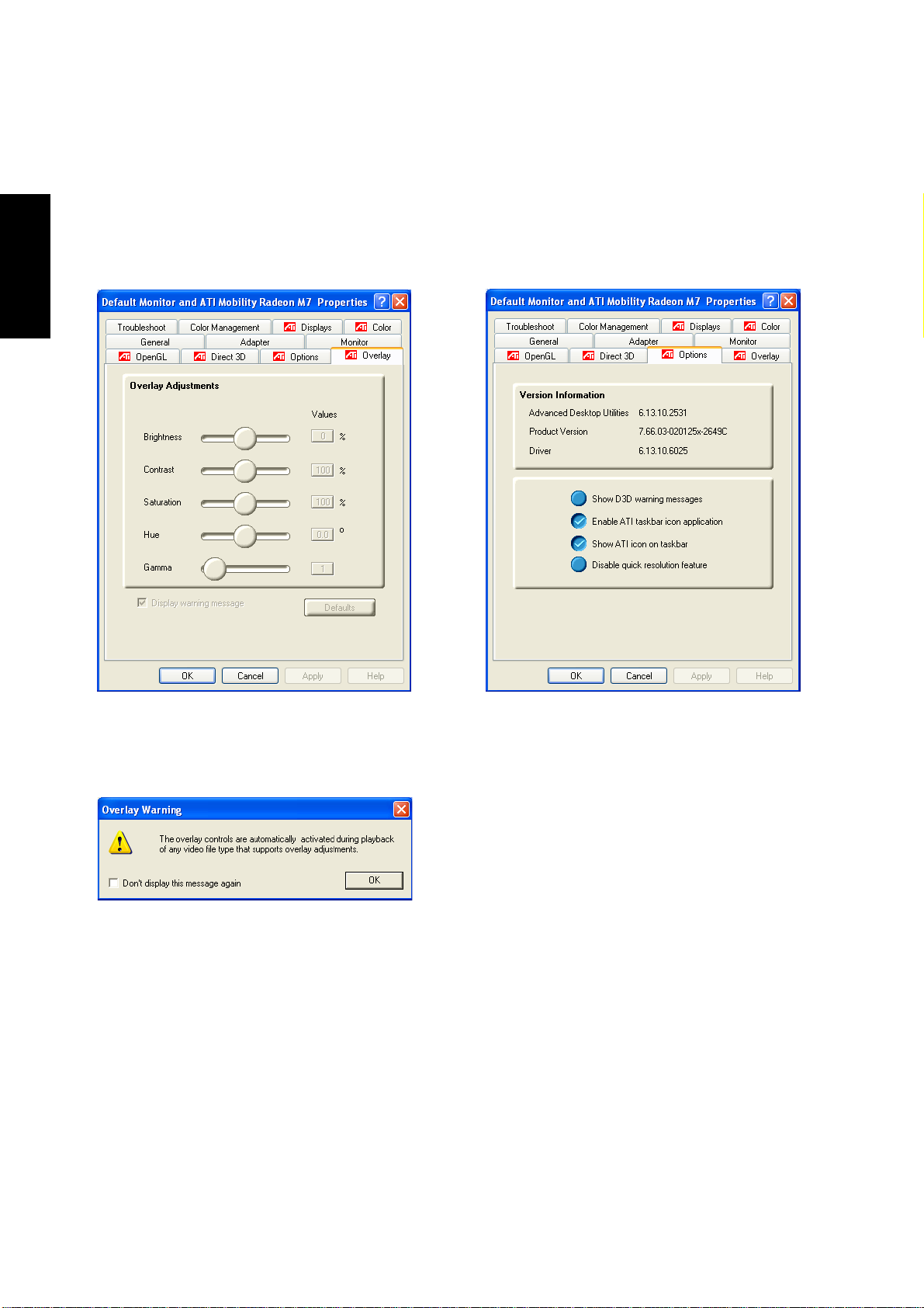
Overlay
This page allows you to make color and brightness settings for video playback.
Overlay Warning
The overlay controls are automatically activated
during playback of any video file type that supports overlay adjustment. This is to explain that
you will only see the results of these settings in
certain video files.
12
Options
This page allows you to enable or disable a few
ATI options.
Page 13
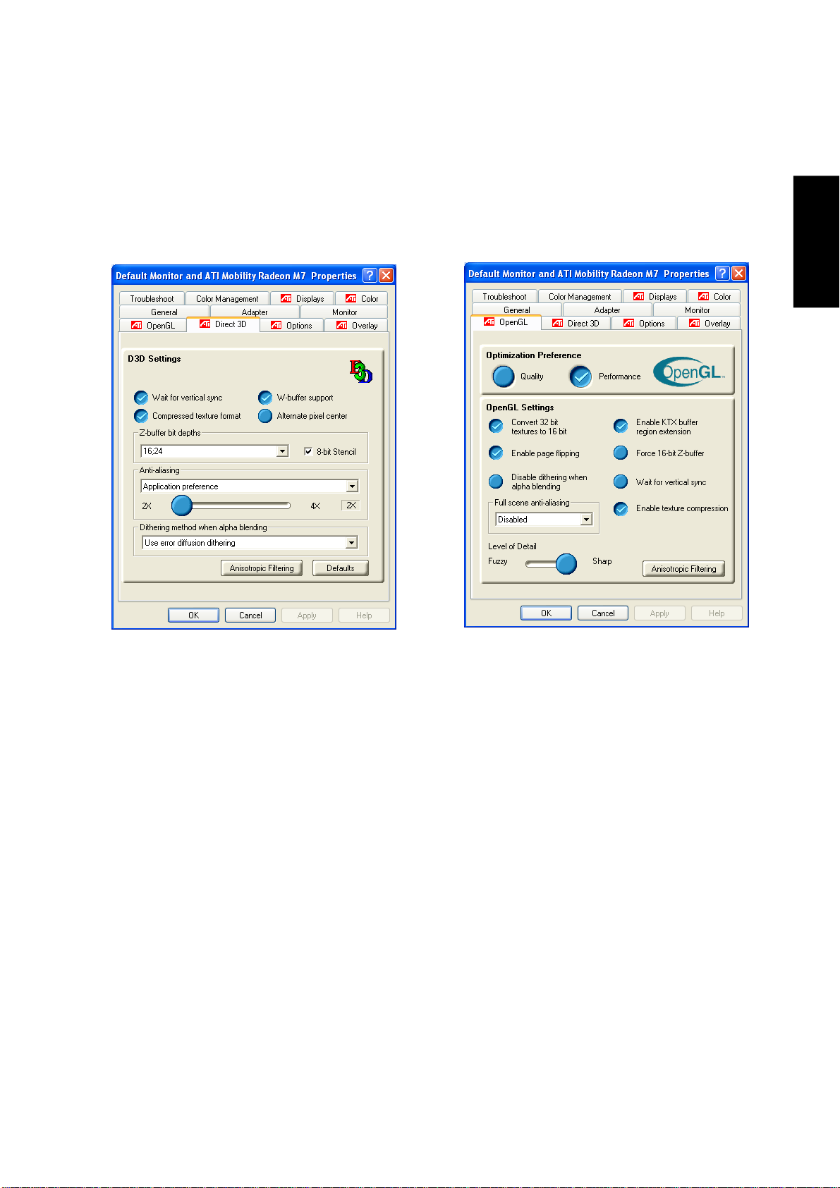
Only the tabs with the ATI logo are installed with the Notebook PC’s VGA driver. The other tabs are part of
the Windows operating system and will not be shown here.
Software Reference
Direct 3D
This page allows you to make Direct 3D settings.
Settings will not be utilized unless you run an
application specifically using Direct 3D.
OpenGL
This page allows you to make OpenGL settings.
Settings will not be utilized unless you run an
application specifically using OpenGL.
13
Page 14
Software Reference
Only the tabs with the ATI logo are installed with the Notebook PC’s VGA driver. The other tabs are part of
the W indows operating system and will not be shown here.
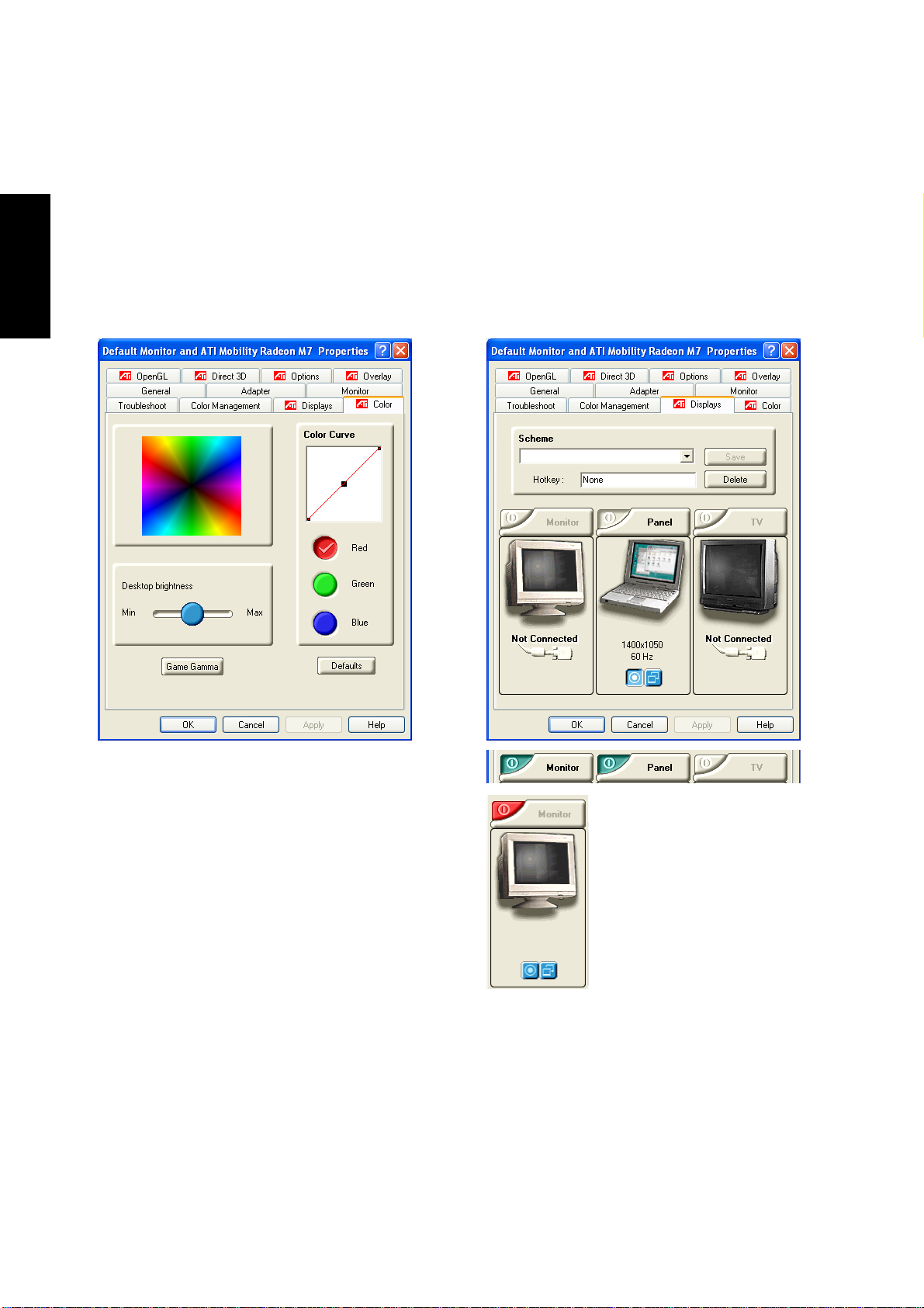
Color
This page allows you to make color, brightness,
and gamma adjustments for each RGB color individually or all together.
When changes are made, Defaults can be used
to easily return to factory settings.
14
Display connections will be
auto-detected and “Not Connected” will be shown for displays that are not detected.
If additional displays are detected, the ON/OFF button
will be shown with Green representing ON and Red represented OFF.
Page 15

Intel Application Accelerator
Topics Covered:
Overview
Operating Systems not supported
General Features
Component Overview
Parameters
Software Reference
Screens will vary depending on your operating system but the contents should be the same.
15
Page 16

Software Reference
Overview
The Intel® Application Accelerator is a software package designed specifically to increase the performance
of applications and computer systems running Intel® Pentium® III or Pentium® 4 Processor . This is achieved
by use of several methods:
1. Intel
put subsystem transfer rate, greatly enhancing the system speed.
2. Intel
systems running Microsoft* Windows* 2000 Professional and Windows XP only, an overall addi-
tional performance enhancement is realized for Windows 2000 and Windows XP - based applica-
tions.
Software installation is flexible and fully automated for Microsoft* Windows* 98, Windows 98 Second
Edition (SE), Windows Millennium Edition* (Me), Windows NT* 4.0, Windows 2000 Professional, and
Windows XP Home Edition and Professional operating systems.
Operating Systems not supported
• Any Version of Microsoft Windows 3.1
• Any Version of Microsoft Windows 95
• Any Version (including service pack) of Microsoft Windows NT 3.51
®
Application Accelerator Driver - This technology increases the performance of the Input/Out-
®
Advanced Pre-Fetch Module - With this technology , available for Pentium® 4 processor based
• Microsoft Windows 2000 Server, W indows 2000 Advanced Server, and Windows 2000 Data Center
• Microsoft Windows XP Server, Windows XP Advanced Server, and Windows XP Data Center
• Linux*
• UNIX*
• BeOS*
• MacOS*
• OS/2* (any version)
• DOS
* Other brands and names may be claimed as the property of others.
16
Page 17
General Features
Intel® Application Accelerator has the following fea-
tures available in property pages:
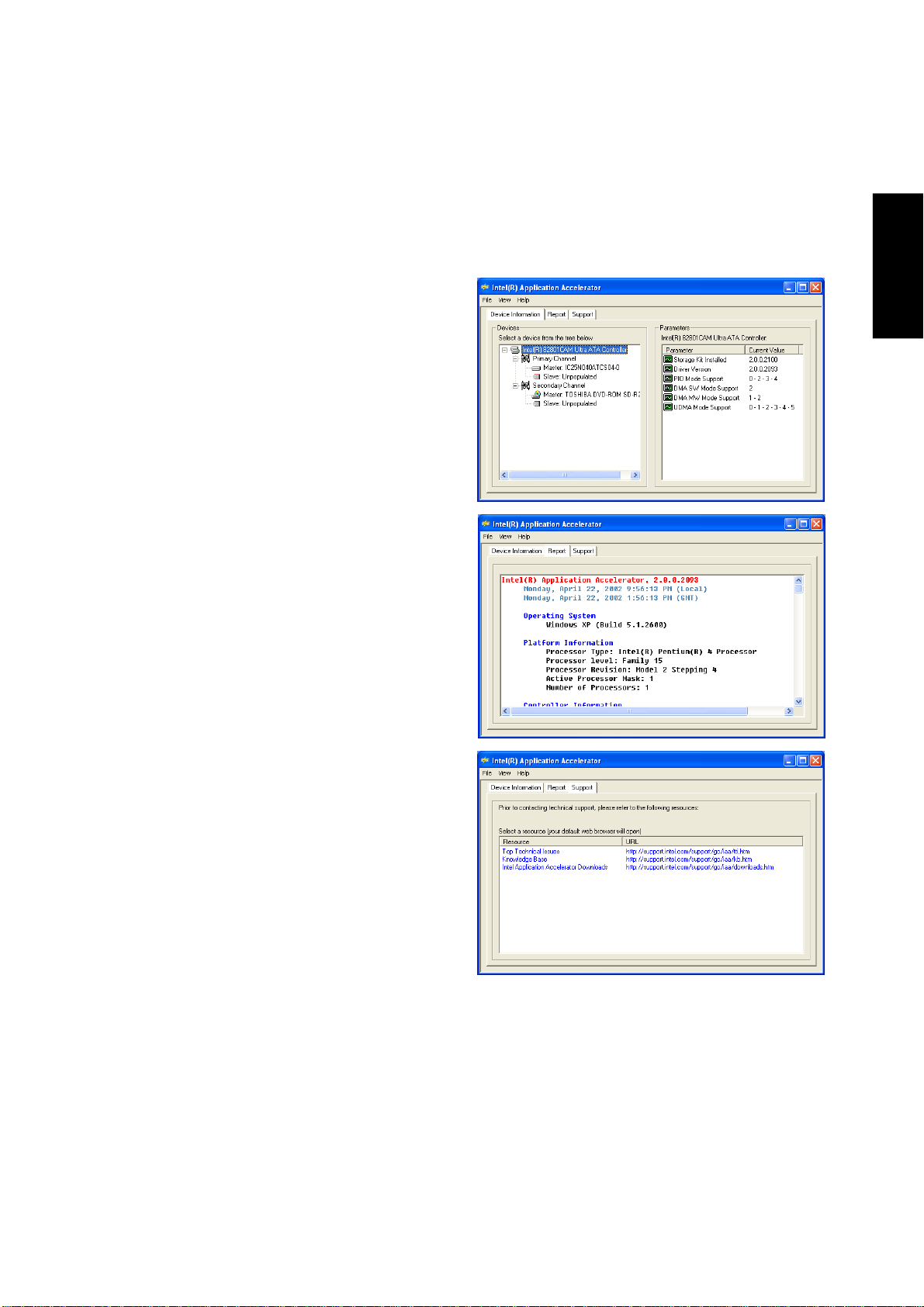
Device Information - This property page, available
for all matching system configurations, displays in-
formation generated and passed-down from the In-
tel® Application Accelerator Driver component. V ari-
ous parameters are seen giving information about the
computer’s IDE drive, transfer rates, and controller
versions.
Report - This property page, available for all match-
ing system criteria’s, displays a report for support
purposes about information relevant to the IDE con-
troller, the IDE channel, and the IDE drive. This
report also has the ability to be printed, saved as a
text file, and viewed in an external viewer.
Software Reference
Support - This property page, available for all
matching system criteria’s, displays support infor-
mation, such as support websites and various string
text for information, as well as any other informa-
tion relevant to support of the product.
* Other brands and names may be claimed as the property of others.
17
Page 18

Software Reference
Component Overview: Intel® Application Accelerator Driver
The Intel® Application Accelerator Driver component is a Windows* Hardware Quality Labs <http://
www.microsoft.com/hwtest/default.asp> (WHQL) certified component designed specifically with the intention to increase the disk to system subsystem speed.
The Intel
and to obtain detailed Ultra AT A Controller and device information, which is displayed in the Device Information Property Page, which can be saved to a file and displayed in the Report Property Page.
In addition, a refresh function can be used to refresh the Device Information Property Page when devices are
swapped under mobile configurations. The refresh function can be activated by pressing the “F5” function
key , located on the keyboard, or by clicking on the menu found at “View” then “Refresh F5”.
Component Overview: Displaying Controller and Device Information
When opened, the Devices window in the Device Information property page contains entries for the Intel
Ultra ATA controller and all connected ATA/ATAPI. Selecting a particular controller or device in the Devices window causes the application to display the corresponding configuration parameters in the Device
Information window . Parameters shown with an oscilloscope icon are read-only; parameters shown with a
wrench icon are read-write. The various parameters are described below on the next screen:
Controller Parameters:
Name Description
IDE Controller Controller product name
Driver Version Device driver version
VxD Build (1) VSD device driver product name
VxD Version (1) VSD device driver version
PIO Mode Support PIO modes supported by controller
DMA SW Mode Support Single-word DMA modes supported by controller
DMA MW Mode Support Multi-word DMA modes supported by controller
UDMA Mode Support Ultra DMA modes supported by controller
®
Application Accelerator has the ability to query the storage component via an IOCTL interface
®
Device Parameters:
Name Description
Firmware Device firmware revision
Serial # Device serial number
PIO Mode Support PIO modes supported by device
DMA SW Mode Support Single-word DMA modes supported by device
DMA MW Mode Support Multi-word DMA modes supported by device
UDMA Mode Support Ultra DMA modes supported by device
Disk Size (2) T otal size of disk
Current Transfer Mode Device’s current, configured transfer mode
Transfer Mode Limit Used to limit Current Transfer Mode, applies
to any device connected to that cable position
Cable Type (Host) Reports if system BIOS recognizes the device
is connected via a 40- or 80-conductor ATA cable
18
Page 19

Synaptics TouchPad
Topics Covered:
Overview of the TouchPad
Scrolling Properties Page
Tap Zones Properties Page
More Features Properties Page
Button Actions Properties Page
Touch Properties Page
Edge Motion Properties Page
Frequently Asked Questions
Software Reference
Screens will vary depending on your operating system but the contents should be the same.
19
Page 20

Software Reference
Overview of Synaptics® TouchPad Features
Your Synaptics TouchPad is much more powerful than an old-fashioned mouse. In addition to providing all
the features of an ordinary mouse, your TouchPad allows you to:
• Tap on the Pad Instead of Pressing the Buttons
• Drag Icons, Windows and Other Objects without Using Buttons
• Adjust the Overall Touch Sensitivity
• Customize Buttons and Taps
• Prevent Accidental Pointing While Typing (also known as Palm Check)
• Scroll Through a Document Without Using Scroll Bars
• Zoom In/Out and Pan on Documents
• Move the Pointer Long Distances
• Fine Tune the Pointer Movement
Tap on the Pad Instead of Pressing the Buttons
T apping on the surface of the pad is the same as clicking the left mouse or TouchPad button (i.e. the primary
T ouchPad button). Tapping is usually quicker and more convenient than using the button. To double-click,
just tap twice. A light, quick tap works best; very hard or very slow taps are less likely to work.
Drag Icons, Windows and Other Objects without Using Buttons
Often, you need to hold the mouse or TouchPad button down while moving the pointer (to move an icon or
window around the screen, for example). This action is called dragging. Just like clicking and double
clicking, you can also drag without using the button.
To move or drag an object (equivalent to pressing and holding the left TouchPad button):
1) Position the pointer over the object and tap twice, down-up-down, leaving your finger on the T ouch-
Pad on the second tap. This action is sometimes called tap-and-a-half.
2) Now move the selected object by sliding your finger across the TouchPad surface.
3) Lift your finger to drop the object.
Tap-and-a-Half
You might wonder what happens when you reach the edge of the pad and you are dragging an object. The
Synaptics T ouchPad has a feature called Locking Drags. This feature allows you to lift your finger from the
pad without ending the drag. You can drag an object across the screen using several finger strokes. T o end
a Locking Drag action, tap again. The Synaptics TouchPad also has a feature called Edge Motion to help
with long distance dragging. See Move the Pointer Long Distances for details.
The Tap and Drag and Locking Drags features are located on the Touch Properties Page in the Mouse
Properties dialog.
20
Page 21

Adjust the Overall Touch Sensitivity
You can control how much finger pressure you must apply before the TouchPad responds by adjusting the
T ouch Sensitivity slider . This slider is located on the Touch Properties Page in the Mouse Properties dialog.
At higher (more sensitive) T ouch Sensitivity settings, the TouchPad recognizes even a very slight touch. If
you see undesired or erratic pointer motion, try a lower setting. Lower (less sensitive) settings require a
firmer touch to move the pointer. In general, a lighter touch works best.
Customize Buttons and Taps
Most T ouchPads come with two buttons that work just like traditional mouse buttons. You can customize the
behavior of these buttons.
T apping on the TouchPad surface also performs the same action as pressing a button. T apping in the center
of the pad will always produce a left-click (the action of the primary button), but you can configure each of
the four corners of the T ouchPad surface to act as different buttons. These special corner regions are called
tap zones . With four corner tap zones, the center of the T ouchPad, and the two physical buttons you can turn
your TouchPad into a seven-button mouse!
A customization example:
Suppose you want to use your TouchPad like a three-button mouse. You can configure the left TouchPad
button to produce middle clicks when pressed. Remember that tapping on the TouchPad will produce left
clicks, and pressing the right TouchPad button will produce right clicks. For additional convenience, you
can configure the top right corner tap zone of the T ouchPad to produce right clicks. Looking at the T ouchPad
surface in the picture below , taps in the top right corner (the red shaded area) will produce right clicks, but
tapping anywhere else on the TouchPad (the solid gray area) produces left clicks.
Software Reference
An Example TouchPad
There are many different actions that you can assign to the buttons and tap zones. The following actions are
provided as built-in features with the Synaptics T ouchPad device driver. Additional actions might be avail-
able if you have installed any third-party TouchPad Plug-In software.
• Jump to the Start Button. This action causes the pointer to jump to the Start button in the Windows
task bar and automatically opens the Start Menu.
• Jump to the current application’s menu. This action causes the pointer to jump to the leftmost entry in
the application’s window menu (usually the File menu) and automatically pops up the submenu.
• Minimize the current application. This action minimizes the current application’s window . If the current
application’s window is already minimized, this action will restore it to its normal size and location.
• Maximize the current application. This action maximizes the current application’s window (expands
it to cover the full screen). If the current application’s window is already maximized, this action will
restore it to its normal size and location.
• Run a program of your choosing. This action allows you to specify the name of any program you
want to run automatically when you click the button or tap in the tap zone.
T o customize taps and buttons, go to the Button Actions Properties Page in the Mouse Properties dialog.
21
Page 22

Software Reference
Prevent Accidental Pointing While Typing
Unintentional pointer movement and accidental taps can be caused by accidentally brushing the surface of
the TouchPad with your palm or another part of your hand. The results of this contact can be observed as a
changing cursor location when typing, causing subsequent text to appear in the wrong place. Or text may
“spontaneously” be highlighted and replaced. Most often, this unwanted pointing activity occurs when typing on the keyboard. The TouchPad can detect and prevent accidental and unwanted pointer movement
while you are typing.
If you see unwanted pointer movement occurring while you are typing, you can adjust the Palm Check slider
located on the Touch Properties Page in the Mouse Properties dialog. Move the slider thumb to the right
towards Maximum. Now accidental brushes of your hand on the TouchPad while you are typing are more
likely to be ignored.
On the other hand, in the midst of typing, you might purposefully use the TouchPad to point and click, and
sometimes the TouchPad may not seem to respond. In this case, move the slider thumb to the left towards
Minimum. Now pointing during typing is less likely to be interpreted as an accidental brush with the pad
surface, and will not be ignored.
Scroll Through A Document without Using Scroll Bars
Virtual Scrolling allows you to perform a very common task – scrolling documents – without having to
move the pointer away from your work. By simply sliding your finger up and down the right edge of the
T ouchPad, the contents of the current window will scroll vertically . Similarly , by sliding your finger left and
right along the bottom edge of the TouchPad, the contents will scroll horizontally. You no longer need to
laboriously maneuver the pointer to the small scroll bar elements; you can scroll no matter where the pointer
happens to be.
V irtual Scrolling works with document windows (like word processors and spreadsheets), and it also works
with file lists, font lists, and other scrollable items. As a rule, you can use Virtual Scrolling when you are
working in any window that has a scroll bar .
And V irtual Scrolling does more than just make scrolling more convenient. It also can make scrolling smoother.
When you scroll by dragging the scroll thumb with the mouse, many applications do not re-display the
document window until you release the mouse button. Virtual Scrolling makes navigation through documents easier, because it forces the application to re-display the window contents as you scroll.
How do I use Virtual Scrolling?
T o customize the Virtual Scrolling feature, go to the Scrolling Properties Page located in the Mouse Properties dialog.
Zoom In/Out and Pan on Documents
Note that zooming and panning only work in applications that support the Microsoft Intellimouse. With
Intellimouse aware applications, you can zoom and/or pan to quickly maneuver your way through lengthy
documents. T o jump to a distant location within your document, zoom out, click on the desired location, then
zoom in. To scroll horizontally and vertically at the same time, simply pan in a diagonal direction!
22
Page 23

Move the Pointer Long Distances
Suppose you are dragging an object, scrolling at high speed (via Virtual Scrolling! ), or merrily moving the
pointer when you suddenly reach the edge of your TouchPad. Don’t despair , the Synaptics TouchPad Edge
Motion feature comes to the rescue! Edge Motion helps with long distance pointer motion. When you reach
an edge of the T ouchPad, the pointer (or scroll thumb when Virtual Scrolling) continues to move in the same
direction until you lift your finger from the TouchPad or move your finger away from the edge.
Edge Motion speed can be pressure-sensitive or constant. Pressure-sensitive speed means that the harder
you press, the faster the object or pointer moves.
You can configure the Edge Motion feature on the Edge Motion Properties Page in the Mouse Properties
dialog.
Fine Tune the Pointer Movement
The Synaptics TouchPad has many additional features to help you control the way your pointer moves.
Please take a look at the list of additional features.
Accessories
Your TouchPad is a productivity enhancing tool, designed for serious work. But we think it should also be
fun. W e have included two fun application programs that demonstrate some of the capabilities of the T ouchPad: Pressure Graph and The Incomparable, Mysterious Synaptics MoodPad.
To run these applications, click once on the Synaptics TouchPad Icon in the Taskbar, go to the Accessories
menu and select the desired application.
Software Reference
More About the TouchPad
The T ouchPad detects your finger by capacitive sensing (it is not sensitive to heat or applied force). As your
finger approaches the pad, it alters the electric field in the vicinity of the pad surface. The TouchPad sensor
is just a circuit board with a matrix of conductive traces printed on the top surface. A special chip on the back
side of the TouchPad continuously measures the capacitance of these traces, and thus can determine the
presence and location of your finger .
T o get the most out of your T ouchPad, be sure that the T ouchPad driver software is installed. If the Synaptics
T ouchPad driver is properly installed, the Mouse Properties dialog will include several TouchPad tabs along
the top in addition to the standard mouse tabs.
Property Pages
The property pages allow you to customize TouchPad settings for your Notebook PC. The following pages
will describe each property page with the Synaptics logo. The “Buttons”, “Pointers”, and “Pointer Options”
pages come with Windows and should be described in Windows documentation.
23
Page 24
Software Reference
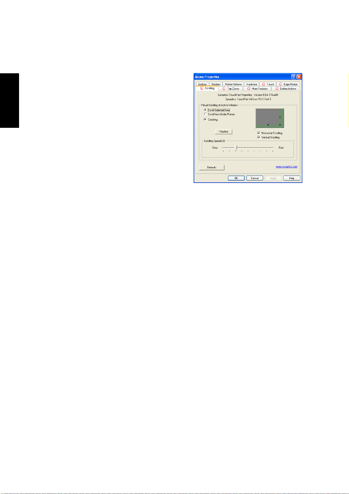
Scrolling Properties Page
The Scrolling properties page allows you to customize the
V irtual Scrolling capabilities of your TouchPad.
In some applications, the scroll zones which activate V irtual
Scrolling can be used for zooming too.
Enabling Virtual Scrolling of the
Active Window
Check the appropriate boxes on this page for the type of V ir tual Scrolling that you prefer:
• Horizontal Scrolling
• Vertical Scrolling
• Coasting
Choose where you want Virtual Scrolling to occur:
• Scroll Selected Item
- OR -
• Scroll Item Under Pointer
Customizing Scroll Zone Sizes
This page includes a small map of the TouchPad with the scroll zones shaded in red. See the Scroll Zone
T ouchPad Map for a more detailed description.
You can adjust the size of each zone by dragging one of the black resize handles on the TouchPad map. If
you are having trouble activating the V irtual Scrolling feature, you might want to try making the scroll zones
wider . If you find that scrolling sometimes gets activated when you didn’t mean to scroll, try narrowing the
scroll zones.
Customizing Virtual Scrolling Speed
Y ou can control the speed of V irtual Scrolling by adjusting the Scrolling Speed slider on this page. Drag the
slider thumb to the right for faster scrolling.
24
Page 25
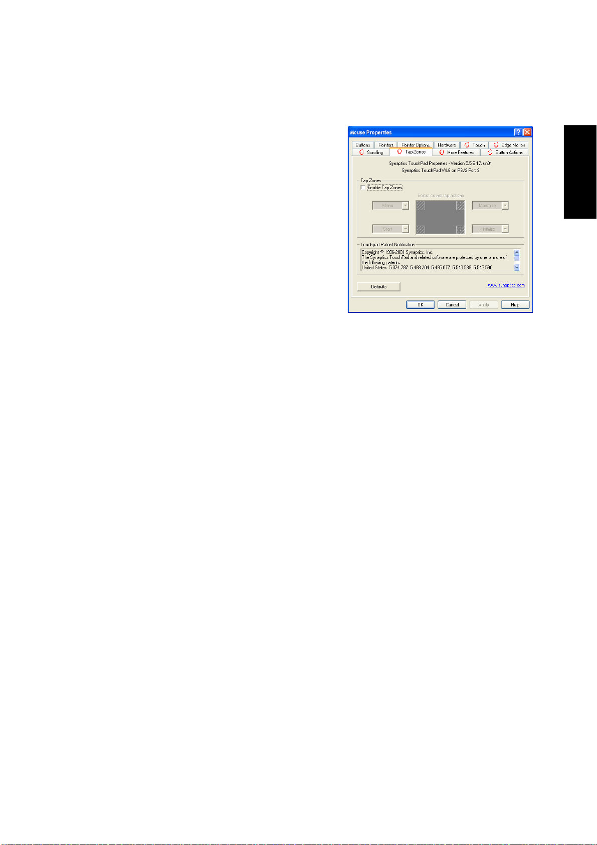
Tap Zones Properties Pages
The Tap Zones properties pages allow you to assign custom
actions to taps in the Touchpad’s corner zone regions (or tap
zone regions).
The Synaptics T ouchPad driver may also control other pointing devices attached to your system. If the Synaptics T ouchPad driver is controlling more than one pointing device on
your system, the Synaptics pages on the Mouse control panel
will have a drop-down box listing all of the pointing devices
that are controlled. You may set separate settings for each by
selecting the appropriate device (settings which don’t apply
to a particular pointing device will be grayed out).
Customizing the Tap Zones
When the tap zones are enabled, each tap inside a corresponding tap zone region on your T ouchPad can have
a different meaning or action. For example, you can define the upper right corner tap zone to mean right
clicks. Then when you tap your finger on the upper right corner of your T ouchPad, it is as if you are clicking
the right mouse or TouchPad button.
This page includes a small map of the T ouchPad with the active tap zones shaded in red. Next to each zone
is a text box specifying the action for that zone.
Software Reference
To Customize:
1. To activate the corner tap zones, check the box next to the text Enable T ap Zones. An unchecked box
means that all taps on every part of the TouchPad surface will have left-click behavior.
2. To change an action for a particular zone, locate the text box nearest the zone. The text box displays
the current action for this zone (for example, it might say No Zone which means that this particular
zone is disabled and any taps here will produce the default left-click action). Click on the down
arrow button located to the right of the text to display a list of actions. Select the desired action.
3. Each tap zone can be resized to be as large or as small as you desire by dragging one of the black
resize handles located on the TouchPad map.
25
Page 26
Software Reference
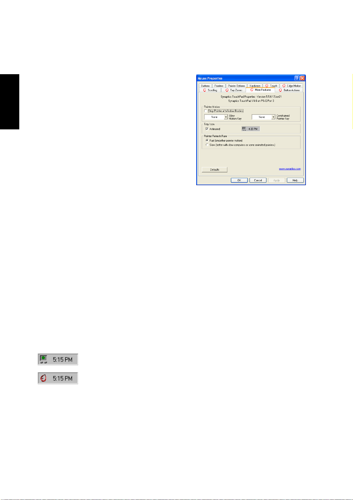
More Features Properties Page
The More Features properties page allows you to control the
following features of you Synaptics TouchPad:
Stop Pointer at Window Borders
This feature constrains the pointer to stay inside the active
window . When you try to move the pointer outside the window , it stops at the edge. If you try a second time, the pointer
is free to leave the window .
Stopping the pointer at the window borders makes it easy to
access controls that lie around the edges of windows. For
example, to close or resize a window, you can casually toss
the pointer in the general direction of the close box or the
edge of the window, and the pointer will stop exactly where
you want it.
Snap to Default Button
This feature automatically moves the pointer to the Default Button when a dialog box appears on your
screen.
Slow Motion Key
Sometimes you might need more accuracy when pointing with the T ouchPad, such as in a drawing program.
The speed of the pointer can make this type of accuracy difficult to obtain. To slow down the pointer movement, you can specify a slow motion key . Then, for slow pointer movement, press and hold this key as you
move the pointer.
Constrained Pointer Key
At times you may want to restrict the pointer to move only horizontally or only vertically . You can specify a
constrained pointer key, then press and hold this key as you move the pointer. The initial pointer direction
when holding this key determines whether the pointer is constrained to move only horizontally or only
vertically .
Synaptics TouchPad Tray Icon
The Synaptics T ouchPad tray icon appears in the W indows Taskbar near the clock. Y ou can
choose between two icons:
This is the animated T ouch Meter icon. The size of the dot on the touch meter indicates the
amount of finger pressure. The icon turns blue while Virtual Scrolling is in progress.
This is the non-animated Synaptics logo icon.
You can access the “TouchPad Properties” dialog by double clicking on either tray icon.
26
Page 27

Button Actions Properties Page
The Button Actions properties page allows you to customize
the physical buttons of your TouchPad.
The Rocker Switch settings are available on Notebook PC’s
with scroll buttons between the left and right buttons.
Customizing Button Assignments
You can customize the TouchPad buttons in the same way
that you customize the tap zones.
To Customize:
Each button has a text box that displays the current action
(for example, it might say Left, which means the left-click or
primary-click action). To display a list of possible actions, click on the down arrow button located to the
right of the text. Select the desired action.
Software Reference
27
Page 28

Software Reference
Touch Properties Page
The Touch properties page allows you to customize the tap
response and sensitivity of your TouchPad.
Taps
Check the appropriate boxes in the T aps section of the Touch
Properties Page for the tapping capabilities that you prefer:
• Tap to Click
• Tap and Drag
• Locking Drags
Touch Sensitivity
Use the Touch Sensitivity slider to control how much finger
pressure you must apply before the T ouchPad responds. See
Adjust the Overall Touch Sensitivity .
Palm Check
The Palm Check slider controls the TouchPad’s detection of accidental and unwanted pointing movement.
In addition to detecting palm contact with the TouchPad, the TouchPad can ignore much of the accidental
and unwanted pointer movement that may occur while typing (due to accidentally contacting your TouchPad). See Prevent Accidental Pointing While Typing for more details.
28
Page 29

Edge Motion Properties Page
The Edge Motion properties page allows you to customize
the long distance pointer motion capabilities of your TouchPad. When your finger reaches the edge of your TouchPad,
the Edge Motion feature allows the pointer to continue to
move until you lift your finger. See Move the Pointer Long
Distances for more details about the Edge Motion feature.
Enabling Edge Motion
Check the appropriate boxes on this page for the types of
Edge Motion that you desire:
• When Dragging
• Always
• When Scrolling
Customizing Edge Zone Sizes
This page includes a small map of the TouchPad with the edge zones shaded in red. See the Edge Zone
T ouchPad Map for a more detailed description. You can adjust the size of each zone by dragging one of the
black resize handles on the TouchPad map. If you are having trouble activating the Edge Motion feature,
you might want to try making the edge zones wider.
Customizing Edge Motion Speed
Software Reference
During Edge Motion, the speed at which the pointer (or dragged object or Virtual Scrolling scroll thumb)
moves can be pressure-sensitive or constant. With pressure-sensitive speed, the harder you press the faster
the object or pointer moves. For this type of speed, check the box labeled Control edge motion speed with
finger pressure.
If you prefer a constant speed for Edge Motion, you can adjust the speed with the Edge Motion speed slider
located on this page.
29
Page 30

Software Reference
Frequently Asked Questions
Q: When I use Virtual Scrolling, the pointer jumps over to the scroll bar, and then jumps back where it
came from when I’m done. Is this normal?
A: Yes.
Q: Why doesn’t the Virtual Scrolling feature work in some windows, even though they have a scroll bar?
A: In order to scroll, Virtual Scrolling must be able to “see” the window’s scroll bar. If the scroll bar is
partially obscured by another window, or partially off the screen, then Virtual Scrolling will not
activate in that window. In general, a window’s scroll bar must be entirely on the screen, and fully
visible, in order to use Virtual Scrolling in that window. There is an exception to this rule: Virtual
Scrolling has “special knowledge” about many common types of windows, and can scroll them even
if their scroll bars are not visible on the screen. A very small number of applications use nonstandard
scroll bars that might not work reliably with Virtual Scrolling.
Q: Why do some windows scroll smoothly , while others re-display their contents only occasionally as I
scroll?
A: The way a window responds to its scroll bars is entirely up to the application which owns that win-
dow. Some applications “smooth-scroll,” while others wait until you release the scroll bar before
updating their contents. Virtual Scrolling “knows” about many common applications and window
types, and uses this knowledge to “trick” many windows into smooth-scrolling (Microsoft ® Word
™ document windows, for example, do not normally smooth-scroll, but they do when you use Virtual Scrolling). If Virtual Scrolling does not “know” about a particular type of window, it still approximates smooth-scrolling by causing the window to re-display when your finger slows down or
stops. This can help you more accurately scroll to the right place in a document.
Q: Why does the scroll thumb sometimes “jump around” when I scroll, and not go exactly where the
pointer is?
A: Again, the application actually has complete control over the way the scroll thumb moves. Depending
upon the window contents, some applications will actually prevent you from moving the scroll thumb
to certain locations. Sometimes, the scroll thumb is only “allowed” to come to rest at one or two positions along the scroll bar! In these cases, even if you were to manually drag the scroll thumb with the
pointer, you would find that it would “jump” to a final location when you released it. Virtual Scrolling,
unfortunately, cannot control how applications manage their scroll bars.
Q: Why doesn’t Virtual Scrolling work properly with Microsoft Internet Explorer?
A: Make sure you are using Internet Explorer version 4.01 or later, and that the Use Smooth Scrolling
option on the Advanced page of the Internet Explorer Properties dialog is NOT checked.
30
Page 31

Q: When I press and hold the shift key or the control key (CTRL), the pointer movement is either very
slow or restricted to move only horizontally or only vertically. What is happening?
A: The shift keys and the control keys are special and are used for various things, such as selecting
multiple files in Microsoft Windows Explorer or for zooming in and out on a spread sheet in Microsoft Excel. These keys can also be used for special pointer movement, such as for slowing the
pointer down or for constraining the pointer to move only horizontally or only vertically. For example, you can assign the left shift key to be the Slow Motion Key. Then when you press and hold
the left shift key, the pointer motion will be slower than usual. Note that you can still use this shift
key for other special behaviors! You can still press and hold the left shift key to select multiple files
in Microsoft Windows Explorer, but the pointer motion will also be a bit slower. If you see slow or
constrained pointer movement when pressing shift or CTRL and you want to turn off this special
behavior, go to the More Features Properties Page in the Mouse Properties dialog and uncheck the
appropriate boxes.
Software Reference
31
Page 32

Software Reference
32
Page 33

PC-cillin 2000
Topics Covered:
PC-cillin 2000 Features
What’s New in PC-cillin 2000
Test Virus
What is a Computer Virus?
How Viruses Spread
Virus Writers
Software Reference
Screens will vary depending on your operating system but the contents should be the same.
33
Page 34

Software Reference
Welcome to PC-cillin
Welcome to PC-cillin 2000, Trend Micro’s award-winning antivirus software.
Here’s what PC-cillin will do “straight out of the box”:
• Checks for viruses every time you Open, Copy, Move, or Save a file
• Protects against downloading infected files from the Internet or FTP sites
• Guards against malicious Java applets and ActiveX controls while web surfing
• Monitors your Word and Excel sessions for macro viruses, using MacroTrapTM
• Scans and cleans all files on your hard drive every Friday
• Scans all program files for viruses every month Checks all your saved documents for macro viruses.
Here’s what you can do with just the click of a button:
• Scan every file on your system and clean any infected files
• Scan any file from Windows Explorer or My Computer by right-clicking the file icon
• Scan floppy diskettes and clean any infected files
• Check all of your Word and Excel document(s) for macro viruses
• If you use Outlook Express 4.0 or above or Eudora Pro 4.0 or above email clients, scan your email
message attachments as they are being downloaded from the POP3 email server.
• Manually scan message attachments in your local Outlook folders
No Limits
Of course, if you’re a person who likes to customize your software, there is no limit to the Scan tasks you can
configure PC-cillin to perform.
Y ou can “set and forget” as many tasks as you see fit. For each task, you can select the file types you want to
scan for viruses, the action PC-cillin will take upon finding a virus (Clean the infected file, Delete it, Quarantine it, Pass it, or Rename / Deny Access to it), and other program details.
Scan Engine
V iruses are detected using T rend’s 32-bit, multi-threaded scan engine and a process called pattern matching.
In addition to catching known viruses, PC-cillin detects and intercepts previously unknown polymorphic, or
mutation, viruses.
MacroTrap
Additional layers of protection come from MacroTrap™, Trend’s macro virus scanning engine, which detects and removes both known and unknown macro viruses.
34
Page 35

What’s New in PC-cillin 2000
PC-cillin 2000 includes the following enhancements over the previous version:
• Windows Support: PC-cillin fully supports Windows. Integration with the W indows installer means
that you can install PC-cillin while installing other Windows components. PC-cillin is Windows
compliant.
• Antivirus scanning of POP3 mail: If you use Microsoft Outlook Express 4.01 or above or Eudora Pro
4.0 or above as your email client, Trend PC-cillin 2000 will scan your email messages as they download from the POP3 server. Virus-infected attachments are stopped before they ever reach your computer!
• Virus Scanning of Local Outlook Folders: If you use Microsoft Outlook as your email client, Trend
PC-cillin 2000 provides on-demand scanning of local folders for virus-infected attachments. Trend
PC-cillin will automatically detect an installed copy of Microsoft Outlook on the computer and enable the user interface elements that permit the use of this feature. Please note that this feature does
not scan messages stored on a Microsoft Exchange server, but only scans messages in local folders.
• Incremental V irus Pattern Download: No longer do you have to download the entire virus pattern file
when updating your software. Trend PC-cillin 2000 supports incremental pattern updates whereby
only the virus patterns that have changed since the last update are downloaded. This greatly reduces
the download time, saving time and expense that you have to spend on Internet connection charges.
Software Reference
• PC-cillin Can Scan Virtually All Media: PC-cillin 2000 can scan the following types of drives in
addition to conventional hard disk drives: CD-ROM, CD-R, CD-RW, PD, FDD, DVD, ZIP and
LS120.
• PCSCAN Command Line Scanner Supports Pattern Files Larger Than 1.44 MB: Due to the large
number of known computer viruses that have been identified, the virus pattern file is now too large to
fit on a single 1.44 MB diskette. The emergency rescue disk creation utility can split the virus pattern
file over several diskettes. Additionally, the PCSCAN command line scanner supports virus pattern
files that have been spanned over more than one diskette.
35
Page 36

Software Reference
What is a Computer Virus?
Simply put, a computer virus is a program that replicates. To do so, it will need to attach itself to other
program files (for example, .exe, .com, .dll) and execute whenever the host program executes. Beyond
simple replication, a virus almost always seeks to fulfill another purpose: to cause damage.
Called the damage routine, or payload, the destructive portion of a virus can range from overwriting critical
information kept on your hard disk’s partition table to scrambling the numbers in your spreadsheets to just
taunting you with sounds, pictures, or obnoxious effects.
It’s worth bearing in mind, however, that even without a “damage routine,” viruses allowed to run unabated
will continue to propagate—consuming system memory, disk space, slowing network traffic and generally
degrading performance. Besides, virus code is often buggy and can also be the source of mysterious system
problems that take weeks to understand. So, whether it was written to be harmful or not, a virus on your
system can lead to instability and should not tolerated.
Some viruses, in conjunction with “logic bombs,” do not make their presence known for months. Instead of
causing damage right away, these viruses do nothing but replicate—until the preordained trigger day or
event when they unleash their damage routines across the network.
To learn more about any particular virus, or about viruses in general, you can access Trend Micro’s online
V irus Encyclopedia that comes with the program or visit Trend Micro’s web site at: http://www.antivirus.com
Test Virus
The European Institute of Computer Anti-virus Research, along with antivirus vendors, has developed a test
file that can be used in checking your installation and configuration.
The file is not an actual virus; it will cause no harm and it will not replicate. Rather, it is a specially created
file whose “signature ” has been included in the T rend Micro virus pattern file and as such, can be detected
by the virus engine.
You can download this file from: http://www.antivirus.com/vinfo/testfiles/index.htm!Internet (“http://
www .antivirus.com/vinfo/testfiles/index.htm”)
Alternatively , copy the following text into a text editor and then save the file with a *.com extension.
X5O!P%@AP[4\PZX54(P^)7CC)7}$EICAR-STANDARD-ANTIVIRUS-TEST-FILE!$H+H*
Y ou may need to disable real-time scanning before downloading the file. Once on your machine, you can use
the test virus to see for yourself how PC-cillin’s various scanning features work.
36
Page 37

How Viruses Spread
There are many ways for a virus to enter your system:
• Email attachments
• World Wide Web (WWW) sites
• FTP traffic from the Internet (file downloads)
• Shared network files & network traffic in general
• Demonstration software
• Pirated software
• Shrink-wrapped, production programs (rare)
• Computer labs
• Electronic bulletin boards (BBS)
• Diskette swapping (using other people’s diskettes for carrying data and programs back and forth)
The most likely virus entry points are email, Internet and network connections, floppy disk drives, and
modems or other serial or parallel port connections. In today’s increasingly interconnected workplace (Inter-
net, intranet, shared drives, removable drives, and email), virus outbreaks now can spread faster and wider
than ever before.
Virus Writers
In the typical scenario, it is an individual, working alone, who writes a virus program and then introduces it
onto a single computer, network server , or the Internet. Why? Ego, revenge, sabotage, and basic disgruntlement have all been cited as motivations. Recently, do-it-yourself “virus kits” have been popping up on the
Internet, and macro scripts are becoming both easier to learn and more powerful, putting the capacity to
engineer viruses in the hands of nearly everyone. In other words, no single, likely profile exits by which virus
writers can be described or understood.
Software Reference
So whatever the reason one may have for writing a virus, the important thing is to make certain your company is not victimized, that your data you are responsible for is safe, and that precious time is not wasted
hunting down (and cleaning up after) viruses.
37
Page 38

Software Reference
PC-cillin 2000 Screens
Double click the PC-cillin icon on the
taskbar to bring up the real-time scan
information page.
The real-time scan information page displays the current virus pattern number
and the current files being scanned. Y ou
can check the additional scan types to
enable virus checking for web or email.
Click the large Main button to view the
program’s settings.
38
The PC-cillin software has features to protect you from Virus
threats. Use the Help for more information.
Page 39

Hotkey Utility
Topics Covered:
Hotkey Utility
Buttons
Hotkey Actions
Adding a Program to Run
Software Reference
Screens will vary depending on your operating system but the contents should be the same.
39
Page 40

Software Reference
Hotkey Utility
Buttons
Add a Hotkey
Delete a Hotkey
Edit Hotkey
Enable all Hotkeys
Disable all Hotkeys
Delete all Hotkeys
Delete a Hotkey
Highlight a Hotkey and click this button to delete it from the current category .
The functions of
the buttons located on the left
side of the program window are
labeled here.
Add a Hotkey
Y ou can assign three Hotkeys to the two preset
by the utility for a maximum of five. If you
don’t use the two preset, you can delete them
for your own applications.
When you choose to add a hotkey, you can
specify a key by pressing that key or key combination in the Hotkey box (the <Fn> key cannot be entered and will be automatically added
to the “Notebook Fn Hotkey” category). The
available Hotkey actions for assignment are
shown in the “Hotkey Action” pull down.
If you did not select a Hotkey, a message will
show:
Delete all Hotkeys
Deletes all Hotkeys in the current category . This
confirmation will be shown:
40
If you already have five hotkey settings, you
will get this message.
Edit a Hotkey
Highlight a Hotkey and click this button to
change its Hotkey or action.
You can enter any information just like adding
a Hotkey .
Page 41

Enable all Hotkeys
Enables all Hotkeys by placing
check marks in front of the
Hotkeys in the current category .
Disable all Hotkeys
Disables all Hotkeys by removing check marks from the front of
the Hotkeys in the current category .
Hotkey Actions
Actions Descriptions Examples (of action)
Software Reference
None: Performs no action --
Move Window To Left: Moves the active window
left between 1-50 steps
Move Window To Up: Moves the active window
up between 1-50 steps
Move Window To Right: Moves the active window
right between 1-50 steps
41
Page 42

Software Reference
Actions Descriptions Examples (of action)
Move Window To Below: Moves the active window
Extend Window From Left: Stretches the active window
Extend Window From Up: Stretches the active window
Extend Window From Right: Stretches the active window
down between 1-50 steps
left between 1-50 steps
up between 1-50 steps
right between 1-50 steps
Extend Window From Below: Stretches the active window
down between 1-50 steps
Shrink Window from Left: Shrinks the active window
from the left between 1-50 steps
Shrink Window from Up: Shrinks the active window
from the top between 1-50 steps
Shrink Window From Right: Shrinks the active window
from the right between 1-50 steps
Shrink Window From Below: Shrinks the active window
from the bottom between 1-50 steps
42
Page 43

Actions Descriptions Examples (of action)
Minimize Window: Minimizes the active window
Maximize Window: Maximizes the active window
Show Normal Size: Shows the active window
in normal size (user adjustable)
Restore: Restores a minimized window
to its previous size.
Log Off: Logs the current user OFF from
the current Windows session and
any connected networks.
Software Reference
Shut Down: Exits from Windows and turns
OFF the Notebook PC.
Reboot: Restarts the Notebook PC
Run Explorer: Runs Windows Explorer
Run Browser: Runs the Internet Browser
Run Program: Runs a user defined program
43
Page 44

Software Reference
Adding a Program to Run
T o add a Hotkey to run a program follow the steps below.
Add a Hotkey
(2) Type a key or key
combination here.
(4) Choose an executable
file using explorer .
(1) Click Add a Hotkey
button.
(3) Choose Run Program
in this pull down menu.
44
(5) Verify your Hotkey and
make sure that it is enabled.
Page 45

Windows Flash Utility (WINFLASH)
Topics Covered:
Updating Your BIOS
Resetting Your BIOS
Software Reference
Screens will vary depending on your operating system but the contents should be the same.
45
Page 46

Software Reference
Updating Your BIOS
WINFLASH is a simple utility to update your Notebook PC’s BIOS.
To run WINFLASH, access the All Programs
shortcut through the Start button.
Do not update your BIOS for no reason.
You will be warned that you should only update
your BIOS if you know it will solve a specific problem. If you update your BIOS using the wrong
BIOS file, your Notebook PC may not boot up.
Example Only
When you enter WINFLASH, you will be immediately asked for the BIOS image file. Browse
to the file and click Open.
46
Compare the BIOS ROM (your current BIOS) to
the BIOS image (the new BIOS). If this is correct, click Flash to write the new BIOS to your
Notebook PC. You need to restart your Notebook
PC and “reset your BIOS”. See instructions on
the next page.
Page 47

Resetting Your BIOS
If you ever hear “reset your BIOS”, it entails pressing [F2] on bootup to enter BIOS setup and selecting Load
Setup Defaults, and then Exit Saving Changes on the “Exit” menu.
Software Reference
47
Page 48

Software Reference
48
Page 49

ASUS PC Probe
Topics Covered:
Starting ASUS PC Probe
Using PC Probe Monitoring
ASUS PC Probe Task Bar Icon
Software Reference
Screens will vary depending on your operating system but the contents should be the same.
49
Page 50

Software Reference
Welcome to ASUS PC Probe
ASUS PC Probe is a convenient utility to continuously monitor your computer system’s vital compo-
nents, such as fan rotations, voltages, and temperatures. It also has a utility that lets you review useful
information about your computer, such as hard disk space, memory usage, and CPU type, CPU speed,
and internal/external frequencies through the DMI Explorer.
Starting ASUS PC Probe
If the ASUS Probe icon (magnifying glass) is not shown on the taskbar (see below), click the Windows
Start button, point to Programs, and then ASUS Utility, and then click Probe VX.XX.
When ASUS PC Probe starts, a splash screen appears allowing you to select whether to show the screen
again when you open PC Probe or not. To bypass this startup screen, clear the Show up in next execu-
tion check box.
The PC Probe icon will appear on the taskbar’s system tray indicating that ASUS PC Probe is
running. Clicking the icon once will allow open the PC Probe interface.
Windows XP Taskbar
Windows XP will hide taskbar items. Click the arrow to show running services.
50
Page 51

Using ASUS PC Probe Monitoring
Software Reference
Monitor Summary
Shows a summary of the items being monitored.
Settings
Lets you set threshold levels and polling intervals or refresh times of the PC’s temperature, fan
rotation, and voltages.
Temperature Monitor
Shows the PC’s temperature.
History
Lets you record the temperature monitoring activity by date, time, and target history. Click the
record button and select a date. T o view a previous recording, simply choose that date.
51
Page 52

Software Reference
Information
Hard Drives
Shows the used and free space of the PC’s hard
disk drives and the file allocation table or file system used. Information on other hard drives can be
accessed by clicking on the relevant drive letter.
DMI Explorer
Shows information pertinent to the PC, such as
CPU type, CPU speed, and internal/external frequencies, and memory size.
Memory
Shows the PC’s memory load, memory usage,
and paging file usage.
ASUS PC Probe Taskbar Icon
Right clicking the PC Probe icon will bring up a
menu to open or exit ASUS PC Probe and pause
or resume all system monitoring.
When the ASUS PC
Probe senses a problem
with your PC, portions
of the ASUS PC Probe icon changes to red and
audio alerts will be heard from the speaker.
52
NOTE: PC Probe will constantly use resources to check the system status while
Windows is operating. It is suggested to
exit PC Probe while using high demanding applications.
Page 53

Power4 Gear
Topics Covered:
Benefits of Power4 Gear
Power4 Gear Interface
Power4 Gear Configuration
Software Reference
Screens will vary depending on your operating system but the contents should be the same.
53
Page 54

Software Reference
Benefits of Power4 Gear
Power4 Gear gives you control over power consumption items by allowing you to instantly “shift” from one
power consumption scheme to another. The four preferences or “gears” are shown below . Y ou can change or
“shift” gears by using the Power4 Gear button above the keyboard or by using the task bar icon. Power4 Gear
can also be automatically activated when AC power is removed.
Power4 Gear Interface
Understanding the Power4 Gear buttons
Press the Power4 Gear button above the taskbar to shift between the four gears as labeled below .
The icon may vary depending on your Notebook PC model.
Maximum Performance
High Performance
Medium Performance
Maximum Power Savings
54
Page 55

Using the task bar icon
Right-click the icon on the taskbar for quick access to Power4 Gear settings.
Software Reference
Power4 Gear Modes
When you are using an AC adapter , the Power4 Gear button will switch betwen two modes as shown below .
When you remove the AC adapter, the Power4 Gear button will switch between three modes as shown
below. When you remove or apply the AC adapter, Power4 Gear will automatically shift you up or down into
the proper mode segment.
AC Mode
Segment
Battery Mode
Segment
55
Page 56

Software Reference
Power4 Gear Configuration
Double click an item to bring up a menu of selections and click on a value to change. To save, select “Save
Configuration” form the “File” pull-down menu. If you did not save, you will be prompted to when you exit.
Maximum Performance High Performance
Medium Performance Maximum Power Savings
See next page for available selections for each “gear”.
56
Page 57

System Standby Timer CPU Performance
Hard Drive Off Timer
Software Reference
Display Panel Off Timer
Display Panel Brightness
(in Medium Performance or Maximum Savings)
57
Page 58

Software Reference
58
Page 59

Check Mail Utility
Topics Covered:
Check Mail Quick Setup
Check Mail Startup
Software Reference
Screens will vary depending on your operating system but the contents should be the same.
59
Page 60

Software Reference
Check Mail Quick Setup
The support CD provided with this Notebook PC allows you to install Check Mail Utility to monitor and notify
you of incoming email messages waiting in your Microsoft® Outlook or Outlook Express Inbox. The Check
Mail utility was designed for Microsoft Outlook products and may or may not be compatible with other email
applications. Launch Microsoft Outlook Express and setup your email account if not done so already. A blue
light between the two email ( ) icons will blink when there are unread email in your Inbox. Unread email will
be indicated in Outlook by a bold “Inbox (x)” (the x being the number of unread emails).
Check Mail Startup
After installation, “Check Mail” loads with Windows and runs in the background.
Using Windows Start Menu
Using MS Configuration
T o run ChkMail, access the All Programs shortcut through the Start button.
60
Run the msconfig utility from the Start button.
On the Startup page, you will see “Startup” items.
ASUS ChkMail is set to startup with Windows.
You can deselect the items you do not want to
startup with W indows.
Page 61

LAN Settings
Topics Covered:
Joining a Domain or Workgroup
Software Reference
Screens will vary depending on your operating system but the contents should be the same.
61
Page 62

Software Reference
Configuring the Network Device
Joining a Domain or Workgroup (Windows XP)
(1) Click Start and My Computer.
(3) Your computer name, workgroup or
domain information is shown here.
Click Change to view options.
(2) Click View system information.
You cannot use spaces or symbols in
the computer name. In the example here,
a warning is given when trying to use
“Notebook PC”. You can use the single
word “Notebook” instead.
62
Page 63

Software Reference
(4a) Domain:
The primary server in the domain will perform routing functions and security verifications for your computer. Select Domain and
enter an existing domain you wish to join.
NOTE: After clicking “OK”, you will be asked
for the Domain Controller’s Administrator
password to join the domain in Windows XP .
(4b) Workgroup:
If your network does not have a domain or
you are not authorized to join a domain,
select Workgroup and type in an existing
name or create your own (by typing an
unused workgroup name)
Administrator Name or Password not
accepted: You cannot login with the Ad-
ministrator name and use one password,
then use the Administrator name with another password to add to a domain. You
must login using another name. See Windows documentation to “Add New User”
from User Accounts in the Control Panel.
63
Page 64

Software Reference
(5) After you restart your computer, you
should see some contents through Entire Network.
Viewing Your Network
(6) Clicking on “My Network Places” will dis-
play networks which you have installed protocols for. Clicking a network protocol such
as “MS Windows Network” will display all
the servers available under that protocol.
64
Page 65

Configuring the BIOS
Topics Covered:
BIOS Setup Program
Main Menu
IDE Channels
Advanced Menu
I/O Device Configuration
Security Menu
Power Menu
Boot Menu
Exit Menu
BIOS Setup
Screens will vary depending on your Notebook PC model but descriptions should be the same.
65
Page 66

BIOS Setup Program
This Notebook PC supports a programmable EEPROM that stores the BIOS software and can be updated using the provided flash memory writer utility. This Section will guide you through the BIOS
setup program by providing clear explanations for all the options. A default configuration has already
been set. If you are either installing new devices or expanding main memory , you will need to enter the
BIOS Setup to reconfigure your Notebook PC.
BIOS Setup
A battery backed-up CMOS RAM is used to record some basic system hardware information: clock,
date, time, the error handling, and etc., even when the power is off. When the Notebook PC is turned
back on, the system is configured with the values stored in the CMOS RAM.
The settings made in the BIOS Setup program intimately affect how the Notebook PC performs. It is
important, therefore, to first understand all the Setup options, and second, to make settings appropriate
for the way you use the Notebook PC.
The BIOS (Basic Input and Output System) Setup is a menu driven software utility that enables you to
make changes to the system configuration and tailor your Notebook PC to reflect installed hardware,
alter performance, and setup power saving functions. BIOS setup is used if you are setting up the
Notebook PC for the first time, reconfiguring your system, or prompted to “Run Setup” during bootup.
This section describes how to configure your system using this utility.
Even if you are not prompted to use the Setup program, at some time in the future you may want to
change the configuration of your Notebook PC. For example, you may want to enable the Security
Password Feature or make changes to the power management settings. It will then be necessary to
reconfigure your system using the BIOS setup program so that the computer can recognize these changes
and record them in the CMOS RAM of the EEPROM.
The Setup program has been designed to make it as easy to use as possible. It is a menu-driven program, which means you can scroll through the various sub-menus and make your selections among the
predetermined choices.
When you start up the computer, press [F2] to call up the Setup utility.
NOTE: Because the BIOS software is constantly being updated, the following BIOS
screens and descriptions are for reference purposes only and may not exactly reflect
your BIOS screens.
Updating your BIOS
This Notebook PC supports an easy-to-use BIOS update software called “WINFLASH” which is installed through the provided support CD. If you need help installing or using “WINFLASH”, refer to
the “Driver & Utility Manual”.
66
Page 67

BIOS Menu Bar
The top of the screen has a menu bar with the following selections:
MAIN Use this menu to make changes to the basic system configuration.
ADVANCED Use this menu to enable and make changes to the advanced features
SECURITY Use this menu to set a password to control bootup and control access
to the BIOS setup menu.
POWER Use this menu to configure and enable Power Management features.
BOOT Use this menu to configure the default system device used to locate
and load the Operating System.
EXIT Use this menu to exit the current menu or specify how to exit the Setup program.
T o access the menu bar items, press the right or left arrow key on the keyboard until the desired item is
highlighted.
BIOS Legend Bar
At the bottom of the Setup screen you will notice a legend bar. The keys in the legend bar allow you to
navigate through the various setup menus. The following table lists the keys found in the legend bar and
those that are not with their corresponding alternates and functions.
BIOS Setup
Navigation Key(s) Function Description
[F1] or [Alt H] Displays the General Help screen from anywhere in the BIOS Setup
[Esc] Jumps to the Exit menu or returns to the main menu from a sub-menu
←←
→→
← or
→ (keypad arrow) Selects the menu item to the left or right
←←
→→
↑↑
↓↓
↑ or
↓ (keypad arrows) Moves the highlight up or down between fields
↑↑
↓↓
– (minus) Scrolls backward through the values for the highlighted field
+ (plus) or space Scrolls forward through the values for the highlighted field
[Enter] Brings up a selection menu for the highlighted field
[Home] or [PgUp] Moves the cursor to the first field
[End] or [PgDn] Moves the cursor to the last field
[F9] Resets the current screen to its Setup Defaults
[F10] Saves changes and exits Setup
67
Page 68

General Help
In addition to the Item Specific Help window, the BIOS setup program also provides a General Help
screen. This screen can be called up from any menu by simply pressing [F1] or the [Alt] + [H] combination. The General Help screen lists the legend keys with their corresponding alternates and functions.
Scroll Bar
BIOS Setup
When a scroll bar appears to the right of a help window , it indicates that there is more information to be
displayed that will not fit in the window. Use [PgUp] and [PgDn] or the up and down arrow keys to
scroll through the entire help document. Press [Home] to display the first page, press [End] to go to the
last page. To exit the help window, press [Enter] or [Esc].
Sub-Menu
T ake some time to familiarize yourself with each of the legend keys and their corresponding functions.
Practice navigating through the various menus and sub-menus. While moving around through the Setup
program, note that explanations appear in the Item Specific Help window located to the right of each
menu. This window displays the help text for the currently highlighted field.
Resetting Your BIOS
If you ever hear “resetting your
BIOS”, it entails pressing [F2] on
bootup to enter BIOS setup and then
selecting Load Setup Defaults on
the “Exit” menu.
Note that a right pointer symbol (as shown in the left view) appears to the left of certain
fields. This pointer indicates that a sub-menu can be launched from this field. A submenu contains additional options for a field parameter. To call up a sub-menu, simply
move the highlight to the field and press [Enter]. The sub-menu will then immediately
appear. Use the legend keys to enter values and move from field to field within a submenu just as you would within a menu. Use the [Esc] key to return to the main menu.
Exit Saving Changes
Exit Discarding Changes
Load Setup Defaults
Discard Changes
Save Changes
Item Specific Help
Exit setup utility and
save your changes to
CMOS.
68
Page 69

Main Menu
When the Setup program is accessed, the main menu screen appears as shown:
System Time [17:15:00]
System Date [04/02/2002]
Legacy Diskette A [1.44M, 3.5 in.]
Primary Master [Auto]
Secondary Master [Auto]
Display Expansion [Enabled]
TV Display Type [NTSC]
Installed Memory 256 MB
CPU Speed 1700 MHz
BIOS Revision XXXX.XXX
Item Specific Help
<Enter> to select field;
<+>,<-> to change value.
NOTE: In the following BIOS item descriptions, the item headings in square brackets
represent the default settings for those fields.
System Time
BIOS Setup
Sets your system to the time that you specify (usually the current time). The format is hour, minute,
second. Insert the appropriate information. Use the [T ab] or [Shift Tab] keys to move between the hour,
minute, and second fields.
System Date
Sets your system to the date that you specify (usually the current date). The format is month, day, year.
T ype in the appropriate information. Use the [T ab] or [Shift T ab] keys to move between the month, day,
and year fields.
Legacy Diskette A [1.44M, 3.5 in.
Specifies the type of disk used as drive A. The configuration options are: [1.44M, 3.5 in.]
IDE Channels:
>Primary Master (described later)
>Secondary Master (described later)
69
Page 70

Display Expansion [Enabled]
Display expansion will stretch a low resolution environment (like DOS) to fill the entire LCD display
panel. The configuration options are: [Disabled] [Enabled]
TV Display Type [NTSC]
This sets the video synchronization mode for your video output device (television or video projector).
The setting depends on the territory that your video output device is manufactured for. The configura-
BIOS Setup
tion options are: [NTSC] [PAL]
Installed Memory [256 MB] (display field)
This field displays the amount of extended memory as detected by the system. Unfortunately , this will
not tell you how much is onboard and how much is added to the SO-DIMM socket. You must visually
inspect the SO-DIMM socket if you are considering expanding your memory . You cannot make changes
to this field. This is a display only field.
CPU Speed [1700 MHz] (display field)
This field displays the speed of the CPU. This will vary depending on your Notebook PC model.
BIOS Revision (display field)
This field displays the current BIOS version.
70
Page 71

Primary Master (sub-menu)
This field is used to configure the primary IDE drive installed in the system. To configure a hard disk
drive, select this sub-menu from the Main menu and press the Enter key to enter this sub-menu.
Primary Master [IC25N030ATDA04-0]
Type: [Auto]
Cylinders [ 1024]
Heads [255]
Sectors [63]
CHS Capacity 8422MB
Maximum LBA Capacity 30005MB
Multi-Sector Transfers [Maximum]
SMART Monitoring [Disabled]
PIO Mode [4]
Ultra DMA Mode [5]
Item Specific Help
<Enter> to select the
type of the IDE drive.
[User Type HDD] allows
you to set each entry on
your own.
WARNING: Ultra DMA mode
3/4/5 can be enabled
only when BIOS detects
shielded 80-pin cable.
NOTE: Before attempting to configure a hard disk drive, make sure you have the configuration information supplied by the manufacturer of the drive. Incorrect settings
may cause your system to not recognize the installed hard disk. T o allow the BIOS to
detect the drive type automatically, select [AUTO].
Type: [Auto]
BIOS Setup
Select Auto to automatically detect an IDE type drive. This option only works with standard built-in
IDE drives. If automatic detection is successful, the correct values will be filled in for the remaining
fields on this sub-menu.
T o configure a drive manually, select User Type HDD. Manually enter the number of cylinders, heads
and sectors per track for your drive. Refer to your drive documentation or look on the drive for this
information. If no drive is installed or if you are removing a drive and not replacing it, select None. Set
the type to CD-ROM to support a CD-ROM or DVD-ROM drive.
71
Page 72

When “Type” set to [User Type HDD]:
BIOS Setup
Translation Method
Translation method allows you to select the sector addressing method.
[Match Partition Table] is recommended if there is already an OS on the hard drive you are
installing to this Notebook PC.
[Manual] allows you to specify cylinders, heads, and sectors.
[LBA] When Logical Block Addressing is enabled, 28-bit addressing of the hard drive is used
without regard for cylinders, heads, or sectors. Note that Logical Block Access may decrease the
access speed of the hard disk. However, LBA Mode is necessary for drives with greater than
504MB in storage capacity. The configuration options are: [LBA] [LARGE] [Normal] [Match
Partition T able] [Manual]
Cylinders [ ]
This field configures the number of cylinders. Refer to your drive documentation to determine the
correct value to enter into this field. NOTE: T o make changes to this field, the Type field must be
set to User Type HDD and “Translation Method” must be set to Manual.
Heads [ ]
This field configures the number of read/write heads. Refer to your drive documentation to determine the correct value to enter into this field. NOTE: T o make changes to this field, the Type field
must be set to User Type HDD and “Translation Method” must be set to Manual.
72
Sectors [ ]
This field configures the number of sectors per track. Refer to your drive documentation to determine the correct value to enter into this field. NOTE: T o make changes to this field, the Type field
must be set to User Type HDD and “Translation Method” must be set to Manual.
CHS Capacity [ ]
This field shows the drive’s CHS capacity calculated automatically by the BIOS from the drive
information you entered.
Maximum LBA Capacity [ ]
This field shows the drive’s maximum capacity calculated automatically by the BIOS from the
drive information you entered.
Page 73

Multi-Sector Transfers [Maximum]
This option automatically sets the number of sectors per block to the highest number supported by
the drive. This field can also be configured manually. Note that when this field is automatically
configured, the set value may not always be the fastest value for the drive. Refer to the documentation that came with your hard drive to determine the optimal value and set it manually. NOTE:
To make changes to this field, the Type field must be set to User Type HDD. The configuration
options are: [Disabled] [2 Sectors] [4 Sectors] [8 Sectors] [16 Sectors] [32 Sectors] [Maximum]
SMART Monitoring [Disabled]
Self-Monitoring Analysis and Reporting Technology (S.M.A.R.T.) is an interface between a
computer's BIOS and hard disk. It is a feature of the Enhanced Integrated Drive Electronics (EIDE)
technology that controls access to the hard drive. If S.M.A.R.T is enabled, the BIOS can receive
analytical information from the hard drive and determine whether to send the user a warning
message about possible future failure of the hard drive. Ideally, this should allow you to take
proactive actions to prevent impending disk crashes.
PIO Mode [ ]
When enabled, this option speeds up communication between the system and the IDE controller
by using enhanced I/O transfer modes (PIO Modes). NOTE: To make changes to this field, the
Type field must be set to User T ype HDD. The configuration options are: [0] [1] [2] [3] [4]
Ultra DMA Mode [ ]
BIOS Setup
This field auto detects Ultra DMA capability (for improved transfer speeds and data integrity) for
compatible IDE (Integrated Disk Electronics) devices. Set to Disable to suppress Ultra DMA
capability.
NOTE: To make changes to this field, the Type field must be set to User Type HDD. The con-
figuration options are: [0] [1] [2] [3] [4] [5] [Disabled]. The following is for your reference:
Mode 0 = 16.7MB/s Mode 1 = 25.0MB/s
Mode 2 = 33.3MB/s (ATA/33) Mode 3 = 44.4MB/s
Mode 4 = 66.7MB/s (ATA/66) Mode 5 = 100MB/s (ATA/100)
NOTE: After using the legend keys to make your selections on this sub-menu, press the
[Esc] key to exit back to the Main menu. When the Main menu appears, you will notice that
the drive size appears in the field for the hard disk drive that you just configured.
73
Page 74

Secondary Master (sub-menus)
This field is used to configure the secondary IDE drive installed in the system. T o configure a hard disk
drive, select this sub-menu from the Main menu and press the Enter key to enter this sub-menu.
The fields and options on this sub-menu are the same as the previous menu described earlier. Leave on
the default setting of Auto.
BIOS Setup
Secondary Master [TOSHIBA DVD-ROM SD-R2102]
Item Specific Help
Type [Auto]
PIO Mode [4]
ULTRA DMA Mode [2]
<Enter> to select the
type of the IDE drive.
[User Type HDD] allows
you to set each entry on
your own.
NOTE: The Secondary drive displayed here is an example only . The actual display will
be dependent on the drive you have installed in your Notebook PC. After using the
legend keys to make your selections in this sub-menu, press the [Esc] key to return to
the Main menu.
74
Page 75

Advanced Menu
Selecting Advanced from the main menu bar display the Advanced menu as shown below.
I/O Device Configuration
Internal Pointing Device [Enabled]
Quick Power On Self Test [Enabled]
CPU/Chipset Revision Check [Enabled]
Item Specific Help
<Enter> to go to the
sub-menu.
>I/O Device Configuration (described on next page)
Pressing [Enter] when this field is highlighted calls up a sub-menu for configuring the Notebook PC’s
serial and parallel ports.
Internal Pointing Device [Enabled]
This allows you to turn ON or OFF the Notebook PC’s built-in touchpad. You may disable the internal
touchpad if you use an external mouse and don’t want to accidentally activate the cursor while typing.
Some external pointing devices may have extra functions that may not function without disabling the
Notebook PC’s touchpad. The configuration options are: [Enabled] [Disabled]
BIOS Setup
Quick Power On Self Test [Enabled]
This field speeds up the Power-On-Self Test (POST) routine by skipping certain redundant tests. Configuration options are: [Disabled] [Enabled]
CPU/Chipset Revision Check [Enabled]
When enabled, BIOS will check the revisions of the CPU, North Bridge (NB), and South Bridge (SB)
to make sure that they are mass-production versions and not beta versions. If beta versions are detected,
the following will be sent to Port 80:90h (CPU is incorrect), 91h (NB is incorrect), 92h (SB is incorrect). Configuration options are: [Disabled] [Enabled]
75
Page 76

I/O Device Configuration (sub-menu)
BIOS Setup
I/O Device Configuration
Onboard Serial Port 1 [3F8H/IRQ4]
IR Port [2F8H/IRQ3]
IR Mode [FIR]
DMA Channel [1]
Onboard Parallel Port [378H/IRQ7]
Parallel Port Mode [Normal]
Item Specific Help
<Enter> to select the
I/O Address & IRQ for
Infrared.
NOTE: The presence of sub-items in this menu is dependent on certain relevant settings.
WARNING! Changing the default address and IRQ settings for Serial Port or Parallel
Port can cause conflicts with other system devices or installed peripherals.
Onboard Serial Port 1 [3F8H/IRQ4]
This field allows you to configure the Notebook PC’s serial COM1 port. The configuration options are:
[3F8H/IRQ4] [2F8H/IRQ3] [3E8H/IRQ4] [2E8H/IRQ3] [Disabled]
IR Port [2F8H/IRQ3]
This field allows you to configure the Notebook PC’s IR port. The configuration options are: [3F8H/
IRQ4] [2F8H/IRQ3] [3E8H/IRQ4] [2E8H/IRQ10] [Disabled]
IR Mode [FIR]
The Mode field allows you to select either Standard Infrared (SIR) or Fast Infrared (FIR) commu-
nication mode. The configuration options are: [SIR] [FIR]
DMA Channel [1] (only when above is set to [FIR])
The DMA field allows you to configure the DMA Channel for the selected mode. The configura-
tion options are: [1] [3]
76
Page 77

Onboard Parallel Port: [378H/IRQ7]
This field allows you to configure the Notebook PC parallel port. The configuration options are: [Disabled] [3BCH/IRQ7] [378H/IRQ7] [278H/IRQ5]
Parallel Port Mode: [Normal]
This field allows you to configure the Notebook PC parallel port transmission mode. The configuration options are: [Normal] [EPP] [ECP] [ECP+EPP]
EPP Mode: When the EPP mode is selected, the standard and bidirectional modes are also available. The EPP operates on a two phase cycle. First, the host selects the register within a device for
subsequent operations. Second, the host performs a series of read and/or write byte operations to
the selected register. There are four operations supported by EPP: Address Write, Data Write,
Address Read, and Data Read. All operations are performed asynchronously.
ECP Mode: The port is both software and hardware compatible with existing parallel ports so that
it may be used as a standard printer mode if ECP is not required. ECP mode provides an automatic
high burst-bandwidth channel that supports DMA for ECP in both the forward (host to peripheral)
and reverse (peripheral to host) direction.
ECP DMA Select: [3] (when above is set to [ECP] or [ECP+EPP])
The DMA field allows you to configure the DMA Channel for the selected mode. The configura-
tion options are: [1] [3]
BIOS Setup
NOTE: After using the legend keys to make your selections for the I/O Device Configuration sub-menu, press the [Esc] key to exit back to the Advanced menu.
77
Page 78

Security Menu
The Notebook PC’s advanced system of security allows you to set a password to prevent unauthorized
access to system resources, data, and the BIOS Setup Program. This Section covers each parameter of
the Security Setup. Selecting Security from the menu bar displays the following menu:
BIOS Setup
The BIOS Setup program allows you to specify passwords in the Security menu. The passwords control
access to the BIOS and certain Security menu options during system startup. The passwords are not
case sensitive. In other words, it makes no difference whether you enter a password using upper or
lowercase letters.
See next page for detailed password information.
Supervisor Password [Disabled]
User Password [Disabled]
HDD Password [Disabled]
Item Specific Help
Supervisor password
controls full access.
<Enter> to change
password ; <Enter> again
to disable password.
78
Page 79

Supervisor Password [Enter]
This protects the BIOS settings. When “Enabled”, you will be prompted for a password after you press
[F2] to enter BIOS setup.
To Enable: Press [Enter], type a password and press [Enter], type the same password again and press
[Enter] to confirm. (You can type up to eight alphanumeric characters. Symbols and other keys are
ignored.)
To Disable: Press [Enter] without entering a password.
User Password [Disabled]
When “Enabled”, you will be prompted for a password during bootup or entering BIOS setup. (To enter
BIOS setup, [F2] must be pressed before the system bootup password prompt.) If the “Supervisor
Password” is enabled, entering a “User Password” will only allow you to gain access to enabling or
disabling the User Password, not the BIOS setup.
To Enable: Press [Enter], type a password and press [Enter], type the same password again and press
[Enter] to confirm. (You can type up to eight alphanumeric characters. Symbols and other keys are
ignored.)
To Disable: Press [Enter] without entering a password.
NOTE: If “User Password” and “Hard Disk Password” are both “Enabled”, the “Hard Disk Password”
will be required first.
HDD Password [Enter]
A HDD (hard disk drive) password places a protection on the hard disk drive so that a password is
necessary in order to access the hard disk drive. When “Enabled”, the hard disk drive will be protected
as follows:
• The protected hard disk drive will prompt for a password when accessed on the Notebook PC.
• The protected hard disk drive cannot be used as a master or slave drive on another computer.
• The protected hard disk drive cannot be formatted.
BIOS Setup
To Enable: Press [Enter], type a password and press [Enter], type the same password again and press
[Enter] to confirm. (You can type up to eight alphanumeric characters. Symbols and other keys are
ignored.)
To Disable: Press [Enter] without entering a password. You will then be asked for the original password to confirm your identity.
NOTE: If “User Password” and “Hard Disk Password” are both “Enabled”, the “Hard Disk Password”
will be required first.
79
Page 80

Power Menu
BIOS Setup
Start Battery Calibration
This function will start a software program to remove memory effects in the battery and recalibrate the
battery gauge. Even though this Notebook PC uses a Lithium-Ion battery which is not prone to memory
effects, memory effects will still occur at the end of the battery’s life cycle. Remember that all recharge-
able batteries only have a definite number of charge and discharge cycles depending on environment
and quality of the battery pack. Follow the instructions shown on the screen.
Start Battery Calibration
Item Specific Help
Press <Enter> to start
calibrating a battery.
The calibration should
charge the battery to
full and then discharge
it to empty.
80
Page 81

Boot Menu
The Boot menu allows the user to specify the order in which the Notebook PC is to check for a device
to boot the system. To make changes, select Boot from the menu bar and the following screen appears:
1. Removable Device [Legacy Floppy]
2. IDE Hard Drive [IC25N030ATDA04-0]
3. ATAPI CD-ROM [TOSHIBA DVD-ROM SD-R2102]
4. Other Boot Device [Disabled]
Onboard LAN Boot ROM [Disabled]
Item Specific Help
Boot Sequence:
<Enter> to select the
device.
To select the boot
sequence, use the up or
down arrow. Press <+> to
move the device up the
list, or <-> to move it
down the list.
Boot Sequence
1. Removable Device
2. IDE Hard Drive
3. ATAPI CD-ROM
4. Other Boot Device
Onboard LAN Boot ROM - Select Network drive bootup capability as [Disabled] or [Enabled].
BIOS Setup
The Boot menu allows you to select among the three possible boot devices listed using the up and down
arrow keys . By using the [+] or [Shift =] keys, you can promote devices and by using the [-] key, you
can demote devices. Press [Enter] to select the specific device or Disabled to never boot from that
device.
Promotion or demotion of devices alters the priority which the system uses to search for a boot device
on system power up. The following are explanations of the devices listed in the boot sequence:
Removable Device refer to the floppy disk used in the internal or USB floppy disk drive.
IDE Hard Drive refers to the internal built-in hard disk drive.
ATAPI CD-ROM refers to either the built-in CD-ROM drive or DVD-ROM drive.
Other Boot Device currently refers to booting from a network drive.
NOTE: To boot from LAN, set this item to the top and Enable “Onboard LAN Boot ROM”.
81
Page 82

Exit Menu
Once you have made all of your selections from the various menus in the Setup program, you should
save your changes and exit Setup. Select Exit from the menu bar to display the following menu:
BIOS Setup
Exit Saving Changes
Item Specific Help
Exit Saving Changes
Exit Discarding Changes
Load Setup Defaults
Discard Changes
Save Changes
Exit setup utility and
save your changes to
CMOS.
NOTE: Pressing the [Esc] key does not exit this menu. You must select one of the
options from this menu or a menu bar item to exit this menu.
Once you are finished making your selections, choose this option from the Exit menu to ensure the
values you selected are saved to the CMOS RAM. The CMOS RAM is sustained by an onboard backup
battery and stays on even when the Notebook PC is turned off. Once this option is selected, a confirmation is asked. Select Yes to save changes and exit.
Exit Discarding Changes
This option should only be used if you do not want to save the changes you have made to the Setup
program. If you have made changes to the fields other than system date, system time, and password, the
system will ask for confirmation before exiting.
82
Page 83

Load Setup Defaults
This option allows you to load the default values for each of the parameters on the Setup menus. When
this option is selected or if [F9] is pressed, a confirmation is requested. Select Yes to load default values
programmed into the BIOS file (the default values may change from one BIOS version to another). You
can now select Exit Saving Changes or make other changes before saving the values to the EEPROM.
Note: Y ou must “Load Setup Defaults” after updating your BIOS.
Discard Changes
This option allows you to discard the selections you made and restore the values you previously saved.
After selecting this option, all selections are updated and a confirmation is requested. Select Yes to
discard any changes and load the previously saved values.
Save Changes
This option saves your selections without exiting the Setup program. You can then return to other
menus and make changes. After selecting this option, all selections are saved and a confirmation is
requested. Select Yes to save any changes to the EEPROM.
BIOS Setup
83
Page 84

BIOS Setup
84
 Loading...