

Page 1

DISASSEMBLY PROCEDURE
K
Disassembly Procedure
Please follow the information provided in this section to perform
the complete disassembly procedure of the notebook. Be sure
to use proper tools described before.
N1Series Notebook consists of various modules. This chapter describes
the procedures for the complete notebook disassembly. In addition, in
between procedures, the detailed disassembly procedure of individual
modules will be provided for your service needs.
Chapter
2
The disassembly procedure consists of the following steps:
• Battery module
• Keyboard Module
• ODD module
• HDD module
• CPU Module
• VGA Card Module
• Memory Module
• W/L Card Module
• LCD Module
• Top cover Module
• Motherboard Module
2 - 1
Page 2
DISASSEMBLY PROCEDURE
BATTERY
Battery module
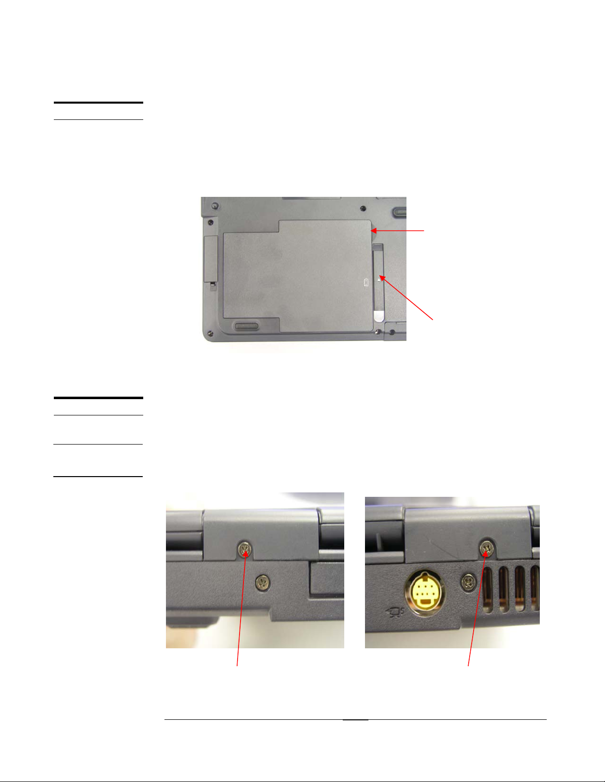
The illustration below shows how to remove the battery module.
1. Turn the notebook over. Unlock one latch (no.1) and remove the battery pack
from bottom side (no.2).
2
1
1
K/B MODULE
K/B COVER
REMOVAL
. Keyboard Module
The illustration below shows how to remove the K/B cover and keyboard plate
Removing K/B cover
.1.Release two screws (no. 1, 2;) from K/B cover on left and right side
1 2
2 - 2
Page 3
K/B COVER
REMOVAL
K/B COVER
REMOVAL
DISASSEMBLY PROCEDURE
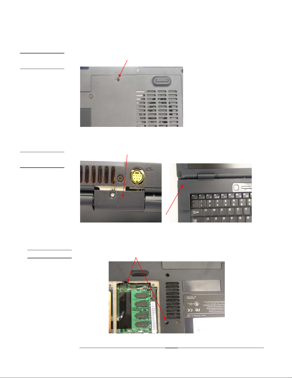
2. Turn the notebook over, release one screws
3. Open K/B cover from rear side, then separate it from left side
K/B REMOVAL
Removing K/B
1. Release K/B 2pcs screw
2 - 3
Page 4
K/B REMOVAL
DISASSEMBLY PROCEDURE
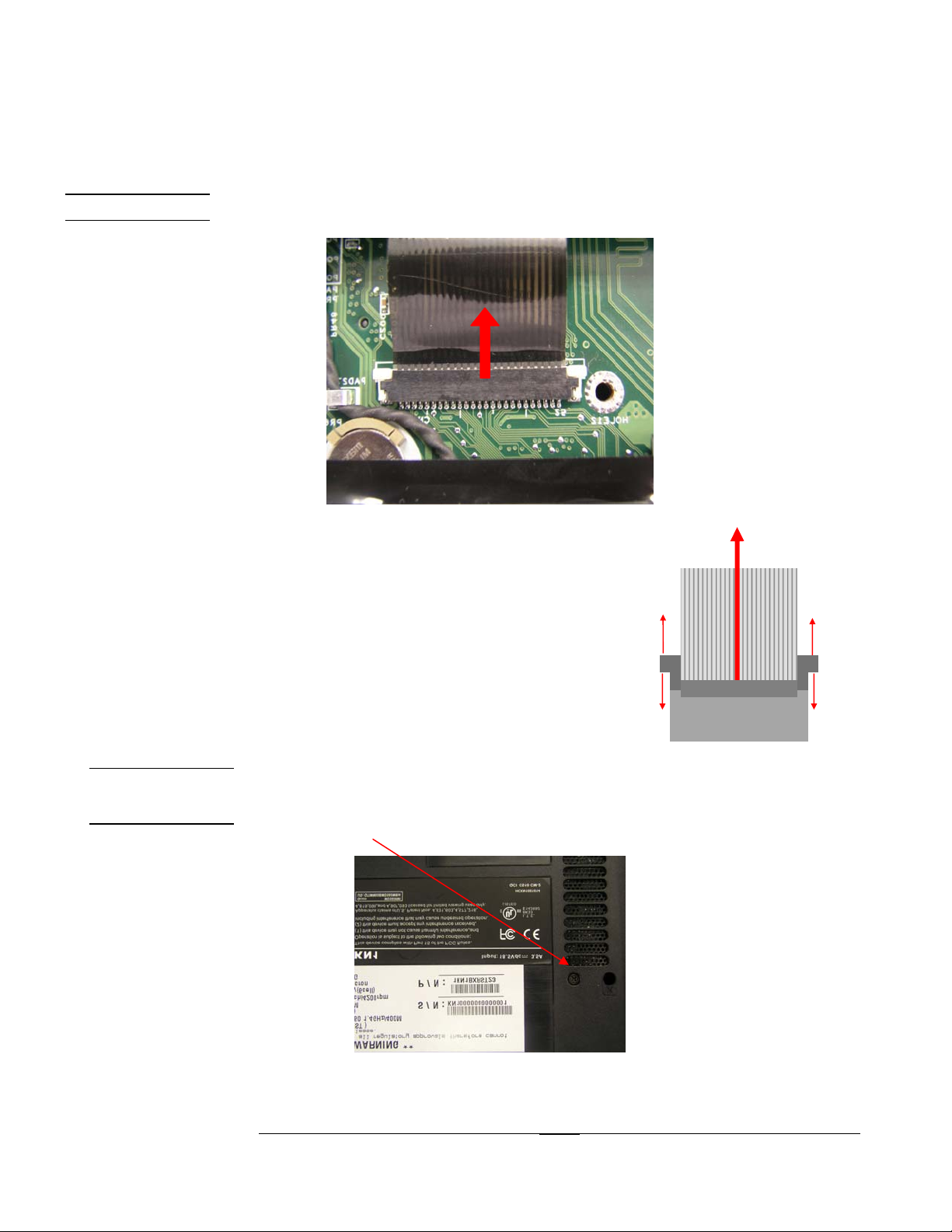
2. Disconnect K/B cable
2. Cable out
1
ROM DRIVER
REMOVAL
. Removing ROM drive
1. Release 1pcs screw
1. Unlock
3.
1. Unlock
3.
2 - 4
Page 5
ROM DRIVER
REMOVAL
DISASSEMBLY PROCEDURE
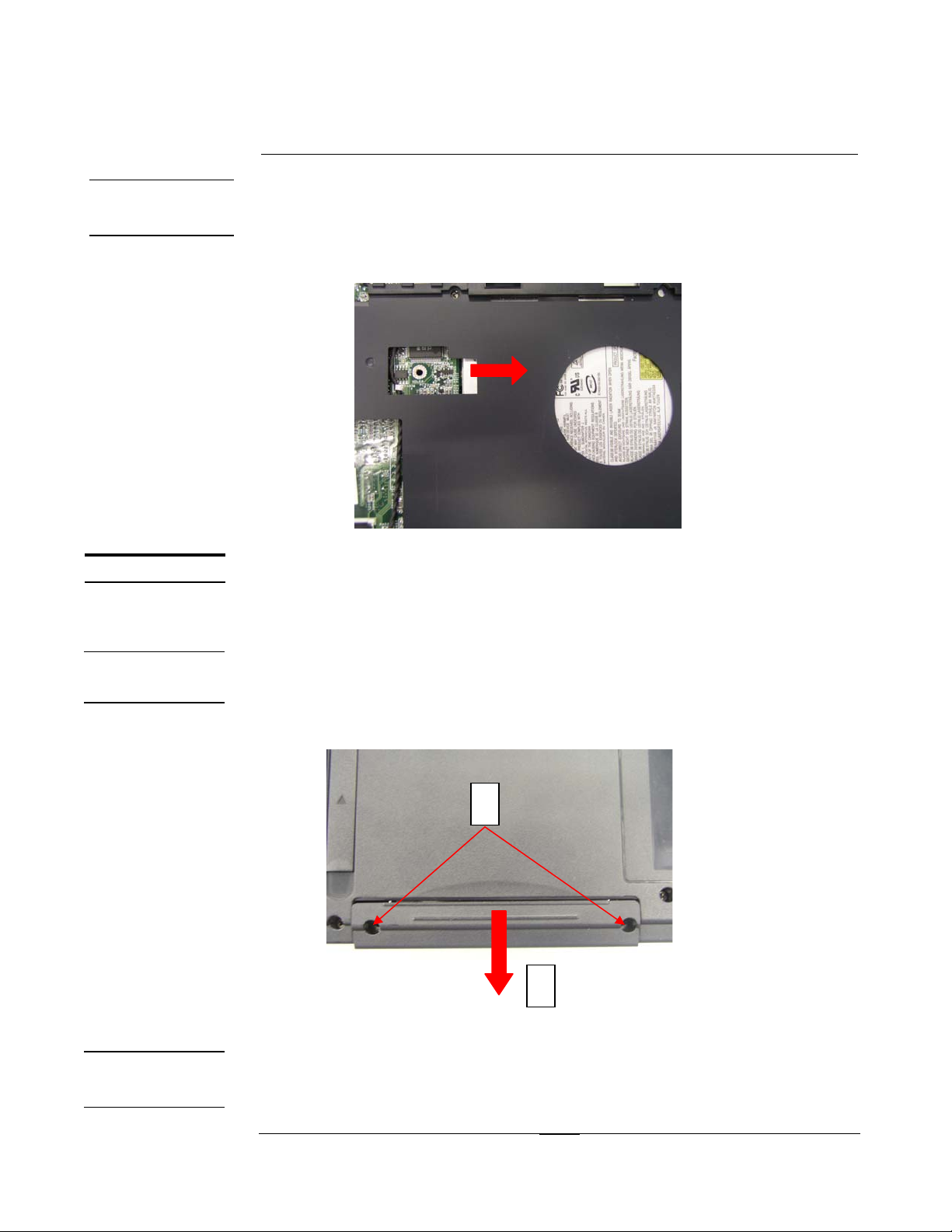
2.Pull out the ODD device from top side
HDD MODULE
HDD MODULE
REMOVAL
HDD MODULE
REMOVAL
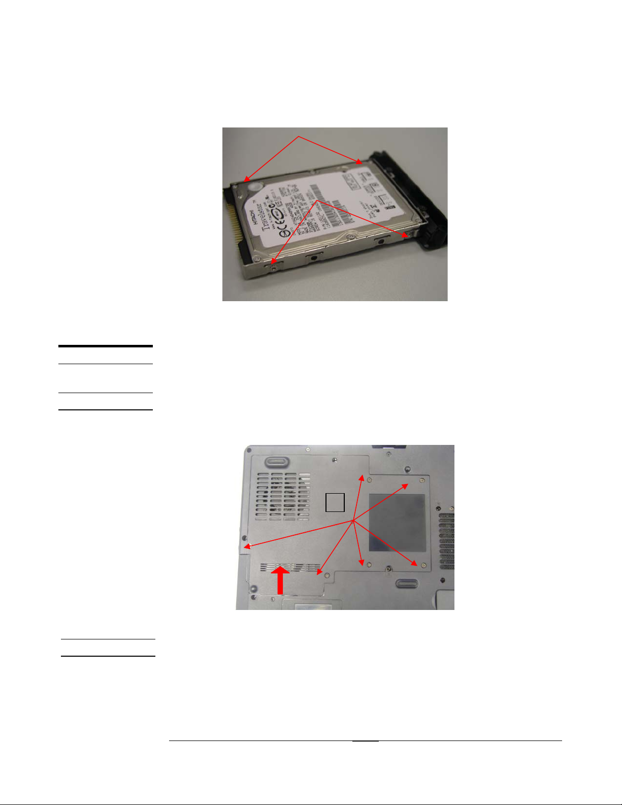
HDD Module
The illustrations below show how to remove the HDD module from the notebook.
Removing HDD Module
1. Release 2 screws from bottom of notebook.
2. Pull out the HDD module from front side of notebook.
1
Disassembling HDD Module
1. Release 4pcs screws on both side of the HDD module.
2
2 - 5
Page 6
1
1
CPU REMOVAL
CPU
DISASSEMBLY PROCEDURE
Please do not touch inside of the HDD module.
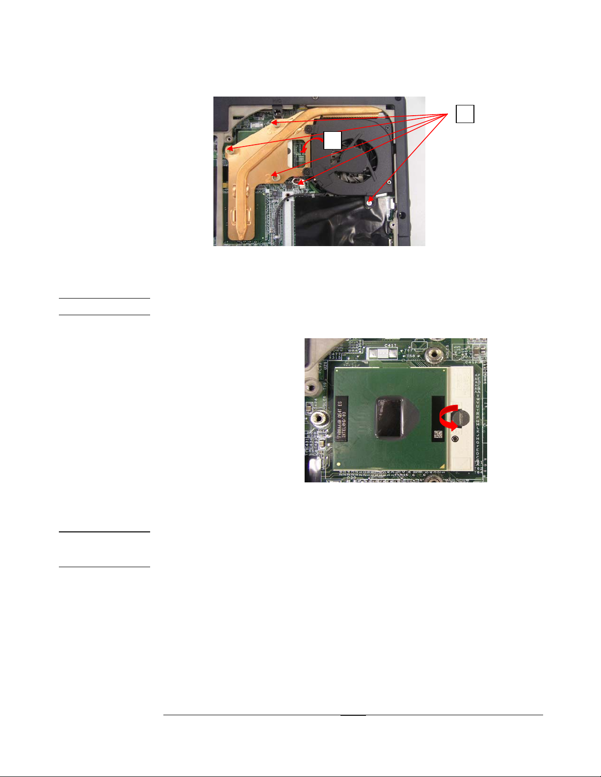
CPU Module
The illustrations below show how to remove the CPU module from the notebook.
The module contains CPU, CPU thermal pad, and CPU thermal module.
Removing CPU
1.Release 6pcs screw on thermal door
2.Remove the thermal door
2
CPU REMOVAL
3. Release 4pcs screw and cable conn
4. Then pull out CPU thermal module
2 - 6
Page 7
CPU REMOVAL
DISASSEMBLY PROCEDURE
VGACARD
REMOVAL
5. Remover CPU
VGA CARD REMOVE
1. Release 4pcs screw on theVGA thermal, then remove VGA thermal
2. Release1pcs screw on theVGA card , then pull out VGA card
2 - 7
Page 8

DISASSEMBLY PROCEDURE
MEMORY
REMOVAL
MEMORY
REMOVAL
Memory Module
The illustrations below show how to remove the Memory module from the notebook.
The KN1 Series Notebook comes standard without memory onboard. There
are two expansion SODIMM sockets for you to upgrade the total memory up to
2GB with two 1024 MB modules
Removing Memory module
If there is an existing memory, remove it by opening the latches, which will pop
the module up to a 45° angle, and then pulling out the module in that angle
2 - 8
Page 9

DISASSEMBLY PROCEDURE
W/L CARD
REMOVAL
W/L CARD
REMOVAL
W/L CARD REMOVE
1. Release 1pcs screw, then remove wireless door
2. Remove antenna , pull out wireless card
2 - 9
Page 10

DISASSEMBLY PROCEDURE
LCD
LCD REMOVAL
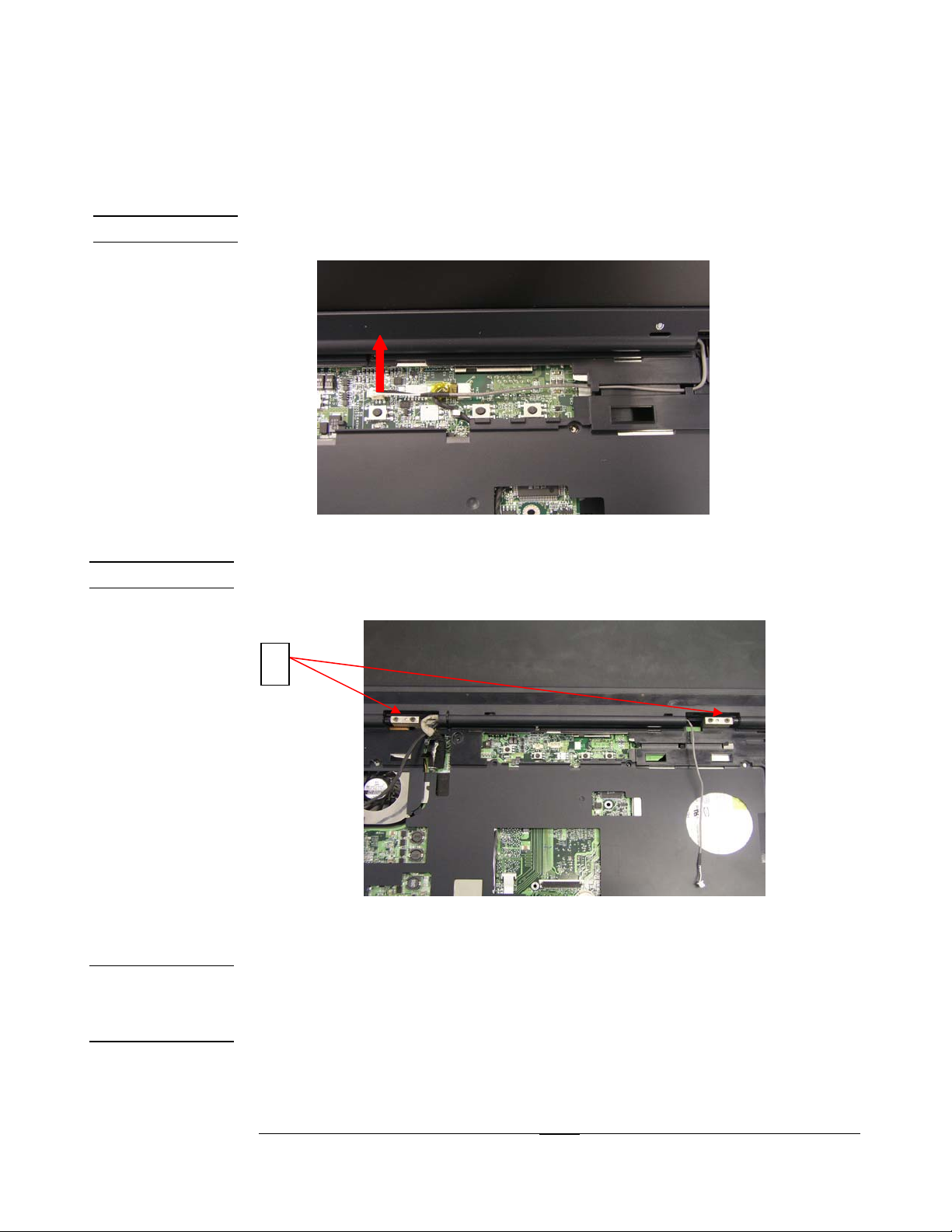
LCD module
The illustrations below show how to remove and disassemble the LCD module.
The module contains LCD panel, inverter board, LCD hinge bracket, hinge
cover, LCD bezel and LCD cover.
Removing LCD Module
1.Disassemble the antenna on base side
LCD REMOVAL
2. Pull out LCD cable conn
3. Disassemble antenna and LCD cable conn
2 - 10
Page 11
LCD REMOVAL
LCD REMOVAL
DISASSEMBLY PROCEDURE
4. Pull out cable conn
5. Release se 4pcs screw on the hinge, remove LCD module
DIS-ASSEMBL
LCD
Y
5
Disassembling LCD Module
1. Remove 4 rubber pads & screws from the LCD module
2. Open inside four edges of LCD bezel with your finger, then remove LCD
bezel form LCD module
2 - 11
Page 12

DISASSEMBLY PROCEDURE
3. Remove 14pcs screws and 1pcs screw on the inverter board
4. Disconnect left and right on the inverter boar
3
2 - 12
Page 13

DISASSEMBLY PROCEDURE
5. Disassemble LCD panel for LCD module, then remove 4pcs screw on
the left and right LCD bracket
TOP COVER
MODULE.
TOP COVER
MODULE
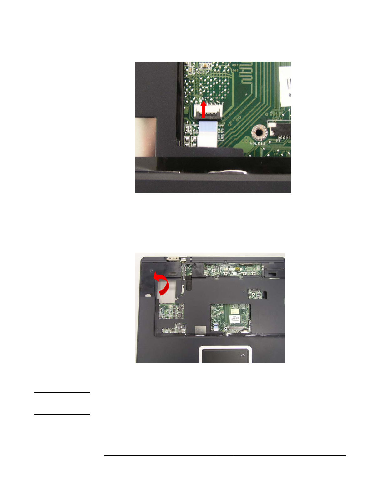
TOP cover module
The illustrations below show how to disassemble and remove the top cover
module of the notebook. The module contains the top cover itself and touch
pad module.
Removing Top cover Module
1. Remove 11pcs screws on the base
2 - 13
Page 14

DISASSEMBLY PROCEDURE
2. Remove 3pcs screw on the top
1
2
3. Release touch pad cable
2 - 14
Page 15
DISASSEMBLY PROCEDURE
4. Remove the top cover from left side
M/BMODULE
REMOVAL
Removing Motherboard module
1. Release 3pcs screw on the M/B and 2pcs nut on the CRT conn
2 - 15
Page 16
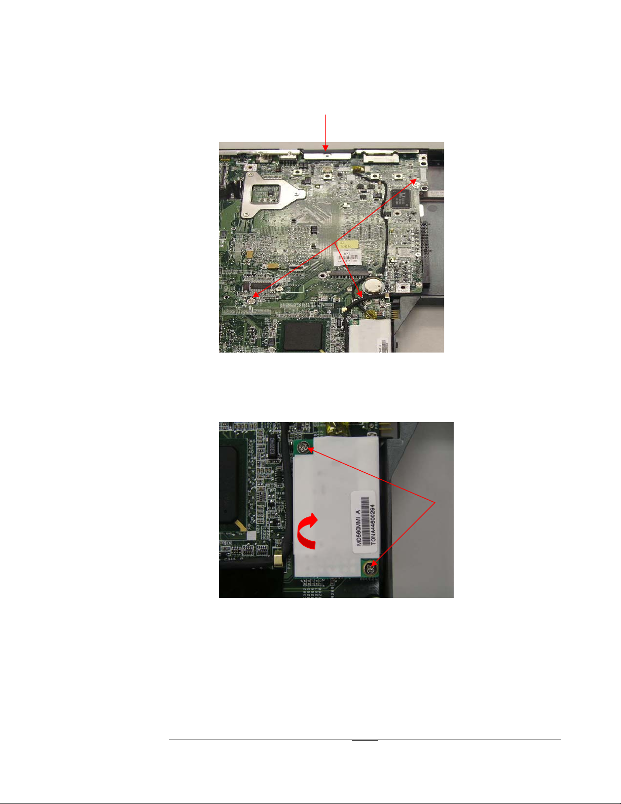
DISASSEMBLY PROCEDURE
2. Release 2pcs screw on modem board, pull out modem board
3. Disconnect speaker cable conn from motherboard
2 - 16
Page 17

DISASSEMBLY PROCEDURE
5. Remove M/B module carefully pry out left side to remove audio jack
first ,then remove IO port from front side to separate the M/B from base
module
2 - 17
 Loading...