

Page 1

H87M-PLUS
Motherboard
Page 2

E8528
Second Edition
July 2013
Copyright© 2013 ASUSTeK COMPUTER INC. All Rights Reserved.
No part of this manual, including the products and software described in it, may be reproduced,
transmitted, transcribed, stored in a retrieval system, or translated into any language in any form or by any
means, except documentation kept by the purchaser for backup purposes, without the express written
permission of ASUSTeK COMPUTER INC. (“ASUS”).
Product warranty or service will not be extended if: (1) the product is repaired, modied or altered, unless
such repair, modication of alteration is authorized in writing by ASUS; or (2) the serial number of the
product is defaced or missing.
ASUS PROVIDES THIS MANUAL “AS IS” WITHOUT WARRANTY OF ANY KIND, EITHER EXPRESS
OR IMPLIED, INCLUDING BUT NOT LIMITED TO THE IMPLIED WARRANTIES OR CONDITIONS OF
MERCHANTABILITY OR FITNESS FOR A PARTICULAR PURPOSE. IN NO EVENT SHALL ASUS, ITS
DIRECTORS, OFFICERS, EMPLOYEES OR AGENTS BE LIABLE FOR ANY INDIRECT, SPECIAL,
INCIDENTAL, OR CONSEQUENTIAL DAMAGES (INCLUDING DAMAGES FOR LOSS OF PROFITS,
LOSS OF BUSINESS, LOSS OF USE OR DATA, INTERRUPTION OF BUSINESS AND THE LIKE),
EVEN IF ASUS HAS BEEN ADVISED OF THE POSSIBILITY OF SUCH DAMAGES ARISING FROM ANY
DEFECT OR ERROR IN THIS MANUAL OR PRODUCT.
SPECIFICATIONS AND INFORMATION CONTAINED IN THIS MANUAL ARE FURNISHED FOR
INFORMATIONAL USE ONLY, AND ARE SUBJECT TO CHANGE AT ANY TIME WITHOUT NOTICE,
AND SHOULD NOT BE CONSTRUED AS A COMMITMENT BY ASUS. ASUS ASSUMES NO
RESPONSIBILITY OR LIABILITY FOR ANY ERRORS OR INACCURACIES THAT MAY APPEAR IN THIS
MANUAL, INCLUDING THE PRODUCTS AND SOFTWARE DESCRIBED IN IT.
Products and corporate names appearing in this manual may or may not be registered trademarks or
copyrights of their respective companies, and are used only for identication or explanation and to the
owners’ benet, without intent to infringe.
Offer to Provide Source Code of Certain Software
This product contains copyrighted software that is licensed under the General Public License (“GPL”),
under the Lesser General Public License Version (“LGPL”) and/or other Free Open Source Software
Licenses. Such software in this product is distributed without any warranty to the extent permitted by the
applicable law. Copies of these licenses are included in this product.
Where the applicable license entitles you to the source code of such software and/or other additional data,
you may obtain it for a period of three years after our last shipment of the product, either
(1) for free by downloading it from http://support.asus.com/download
or
(2) for the cost of reproduction and shipment, which is dependent on the preferred carrier and the location
where you want to have it shipped to, by sending a request to:
ASUSTeK Computer Inc.
Legal Compliance Dept.
15 Li Te Rd.,
Beitou, Taipei 112
Taiwan
In your request please provide the name, model number and version, as stated in the About Box of the
product for which you wish to obtain the corresponding source code and your contact details so that we
can coordinate the terms and cost of shipment with you.
The source code will be distributed WITHOUT ANY WARRANTY and licensed under the same license as
the corresponding binary/object code.
This offer is valid to anyone in receipt of this information.
ASUSTeK is eager to duly provide complete source code as required under various Free Open Source
Software licenses. If however you encounter any problems in obtaining the full corresponding source
code we would be much obliged if you give us a notication to the email address gpl@asus.com, stating
the product and describing the problem (please DO NOT send large attachments such as source code
archives, etc. to this email address).
ii
Page 3

Contents
Safety information ...................................................................................................... vi
About this guide ........................................................................................................ vii
H87M-PLUS specications summary ....................................................................... ix
Package contents ...................................................................................................... xii
Installation tools and components ......................................................................... xiii
Chapter 1: Product Introduction
1.1 Special features..........................................................................................1-1
1.1.1 Product highlights
1.1.2 5X Protection
1.1.3 ASUS Exclusive Features ...........................................................
1.1.4 ASUS Quiet Thermal Solution .....................................................
1.1.5 ASUS EZ DIY ..............................................................................
1.1.6 Other special features .................................................................
1.2 Motherboard overview ...............................................................................
1.2.1 Before you proceed .....................................................................
1.2.2 Motherboard layout .....................................................................
1.2.3 Central Processing Unit (CPU) ...................................................
1.2.4 System memory ..........................................................................
1.2.5 Expansion slots .........................................................................
1.2.6 Jumpers ....................................................................................
1.2.7 Onboard buttons and switches
1.2.8 Onboard LEDs ..........................................................................
1.2.9 Internal connectors
........................................................................ 1-1
............................................................................... 1-2
.................................................. 1-14
.................................................................... 1-16
1-3
1-4
1-4
1-5
1-5
1-5
1-6
1-8
1-9
1-11
1-13
1-15
Chapter 2: Basic installation
2.1 Building your PC system...........................................................................2-1
2.1.1 Motherboard installation ..............................................................
2.1.2 CPU installation
2.1.3 CPU heatsink and fan assembly installation ...............................
2.1.4 DIMM installation
2.1.5 ATX Power connection ................................................................
2.1.6 SATA device connection ..............................................................
2.1.7 Front I/O Connector ....................................................................
2.1.8 Expansion Card installation
2.2 Motherboard rear and audio connections .............................................
2.2.1 Rear I/O connection ..................................................................
2.2.2 Audio I/O connections ...............................................................
2.3 Starting up for the rst time ....................................................................
........................................................................... 2-3
......................................................................... 2-6
....................................................... 2-10
2-1
2-4
2-7
2-8
2-9
2-11
2-11
2-13
2-15
iii
Page 4

2.4 Turning off the computer ......................................................................... 2-15
Chapter 3: BIOS setup
3.1 Knowing BIOS ............................................................................................3-1
3.2 BIOS setup program ..................................................................................
3.2.1 EZ Mode
3.2.2 Advanced Mode ..........................................................................
3.3 My Favorites ...............................................................................................
3.4 Main menu ..................................................................................................
3.5 Ai Tweaker menu ........................................................................................
3.6 Advanced menu .......................................................................................
3.6.1 CPU Conguration ....................................................................
3.6.2 PCH Conguration ....................................................................
3.6.3 SATA Conguration ...................................................................
3.6.4 System Agent Conguration
3.6.5 USB Conguration ....................................................................
3.6.6 Platform Misc Conguration ......................................................
3.6.7 Onboard Devices Conguration ................................................
3.6.8 APM ..........................................................................................
3.6.9 Network Stack ...........................................................................
3.7 Monitor menu ...........................................................................................
3.8 Boot menu ................................................................................................
3.9 Tools menu ...............................................................................................
3.9.1 ASUS EZ Flash 2 Utility ............................................................
3.9.2 ASUS O.C. Prole .....................................................................
3.9.3 ASUS SPD Information .............................................................
3.10 Exit menu ..................................................................................................
3.11 Updating BIOS ..........................................................................................
...................................................................................... 3-3
...................................................... 3-27
3-2
3-4
3-6
3-7
3-9
3-21
3-22
3-24
3-26
3-29
3-30
3-30
3-32
3-33
3-34
3-37
3-43
3-43
3-43
3-44
3-45
3-46
Chapter 4: Software support
4.1 Installing an operating system .................................................................4-1
4.2 Support DVD information ..........................................................................
4.2.1 Running the support DVD ...........................................................
4.2.2 Obtaining the software manuals
4.3 Software information .................................................................................
4.3.1 AI Suite 3
4.3.2 DIGI+ VRM ..................................................................................
4.3.3 EPU .............................................................................................
4.3.4 TurboV EVO ................................................................................
iv
..................................................................................... 4-3
.................................................. 4-2
4-1
4-1
4-3
4-5
4-6
4-7
Page 5

4.3.5 Fan Xpert 2 .................................................................................4-9
4.3.6 USB 3.0 Boost
4.3.7 Network iControl
4.3.8 EZ Update .................................................................................
4.3.9 System Information ...................................................................
4.3.10 Audio congurations
........................................................................... 4-11
........................................................................ 4-12
4-13
4-13
.................................................................. 4-15
Chapter 5: RAID support
5.1 RAID congurations ..................................................................................5-1
5.1.1 RAID denitions ..........................................................................
5.1.2 Installing Serial ATA hard disks ...................................................
5.1.3 Setting the RAID item in BIOS ....................................................
5.1.4 Intel
5.2 Creating a RAID driver disk
®
Rapid Storage Technology Option ROM utility ..................5-3
....................................................................... 5-7
5.2.1 Creating a RAID driver disk without entering the OS ..................
5.2.2 Creating a RAID driver disk in Windows
5.2.3 Installing the RAID driver during Windows
®
.................................... 5-8
®
OS installation ........ 5-8
5-1
5-2
5-2
5-7
Appendices
Notices .................................................................................................................... A-1
ASUS contact information ...................................................................................... A-3
v
Page 6

Safety information
Electrical safety
To prevent electrical shock hazard, disconnect the power cable from the electrical outlet
•
before relocating the system.
When adding or removing devices to or from the system, ensure that the power cables
•
for the devices are unplugged before the signal cables are connected. If possible,
disconnect all power cables from the existing system before you add a device.
Before connecting or removing signal cables from the motherboard, ensure that all
•
power cables are unplugged.
Seek professional assistance before using an adapter or extension cord. These devices
•
could interrupt the grounding circuit.
Ensure that your power supply is set to the correct voltage in your area. If you are not
•
sure about the voltage of the electrical outlet you are using, contact your local power
company.
If the power supply is broken, do not try to x it by yourself. Contact a qualied service
•
technician or your retailer.
Operation safety
Before installing the motherboard and adding devices on it, carefully read all the manuals
•
that came with the package.
Before using the product, ensure all cables are correctly connected and the power
•
cables are not damaged. If you detect any damage, contact your dealer immediately.
To avoid short circuits, keep paper clips, screws, and staples away from connectors,
•
slots, sockets and circuitry.
Avoid dust, humidity, and temperature extremes. Do not place the product in any area
•
where it may become wet.
Place the product on a stable surface.
•
If you encounter technical problems with the product, contact a qualied service
•
technician or your retailer.
vi
Page 7

About this guide
This user guide contains the information you need when installing and conguring the
motherboard.
How this guide is organized
This guide contains the following parts:
• Chapter 1: Product introduction
This chapter describes the features of the motherboard and the new technology it
supports. It includes description of the switches, jumpers, and connectors on the
motherboard.
• Chapter 2: Basic installation
This chapter lists the hardware setup procedures that you have to perform when
installing system components.
• Chapter 3: BIOS setup
This chapter tells how to change system settings through the BIOS Setup menus.
Detailed descriptions of the BIOS parameters are also provided.
• Chapter 4: Software support
This chapter describes the contents of the support DVD that comes with the
motherboard package and the software.
• Chapter 5: RAID support
This chapter describes the RAID congurations.
Where to nd more information
Refer to the following sources for additional information and for product and software
updates.
1. ASUS websites
The ASUS website provides updated information on ASUS hardware and software
products. Refer to the ASUS contact information.
2. Optional documentation
Your product package may include optional documentation, such as warranty yers,
that may have been added by your dealer. These documents are not part of the
standard package.
vii
Page 8

Conventions used in this guide
To ensure that you perform certain tasks properly, take note of the following symbols used
throughout this manual.
DANGER/WARNING: Information to prevent injury to yourself when trying to
complete a task.
CAUTION: Information to prevent damage to the components when trying to
complete a task
IMPORTANT: Instructions that you MUST follow to complete a task.
NOTE: Tips and additional information to help you complete a task.
Typography
Bold text Indicates a menu or an item to select.
Italics
<Key> Keys enclosed in the less-than and greater-than sign
<Key1> + <Key2> + <Key3> If you must press two or more keys simultaneously, the key
Used to emphasize a word or a phrase.
means that you must press the enclosed key.
Example: <Enter> means that you must press the Enter or
Return key.
names are linked with a plus sign (+).
viii
Page 9

H87M-PLUS specications summary
CPU LGA1150 socket for the 4th Generation Intel® Core™ i7/ i5 / i3, Pentium®,
and Celeron® processors
Supports 22nm CPU
Supports Intel® Turbo Boost Technology 2.0*
* The Intel® Turbo Boost Technology 2.0 support depends on the CPU types.
www.asus.com for Intel® CPU support list.
** Refer to
Chipset Intel® H87 Express Chipset
Memory 4 x DIMMs, max. 32GB, DDR3 1600 / 1333 /1066MHz, non-ECC, un-
buffered memory
Dual-channel memory architecture
Supports Intel® Extreme Memory Prole (XMP)
* Hyper DIMM support is subject to the physical characteristics of individual
CPUs. Some hyper DIMMs only support one DIMM per channel. Please refer to
Memory QVL (Qualied Vendors List) for details.
** Due to Intel
*** Refer to
®
on XMP mode will run at the maximum transfer rate of DDR3 1600MHz.
chipset limitation, the DDR3 1600MHz and higher memory modules
www.asus.com or this user manual for the Memory QVL (Qualied
Vendors List).
Expansion slots 1 x PCI Express 3.0/2.0 x16 slot [yellow] (at x16 mode)
1 x PCI Express 2.0 x16 slot [dark brown] (at x4 mode, compatible with
PCIe x1, and x4 devices)
2 x PCI slots
VGA Integrated Graphics Processor - Intel® HD Graphics support
Multi-VGA output support: HDMI / DVI / RGB port
Supports HDMI with max. resolution of 4096 x 2160 @24Hz / 2560 x 1600
@60Hz
Supports DVI with max. resolution of 1920 x 1200 @60Hz
Supports RGB with max. resolution of 1920 x 1200 @60Hz
Maximum shared memory 1024MB
Multi-GPU support Supports AMD® CrossFireX™ Technology
Storage
Intel® H87 Express Chipset with RAID 0, 1, 5, 10 and Intel®
Rapid Storage Technology 12 support
- 6 x SATA 6.0 Gb/s ports (yellow)
- Supports Intel
Technology, and Intel® Smart Connect Technology*
* These functions will work depending on the CPU installed.
LAN Realtek® 8111G Gigabit LAN controller
Audio Realtek® ALC887 8-channel high denition audio CODEC
- Supports Jack-Detection, multi-streaming and front panel jackretasking
* Use a chassis HD audio module in the front panel to support 8-channel audio
output
®
Smart Response Technology, Intel® Rapid Start
(continued on the next page)
ix
Page 10

H87M-PLUS specications summary
USB
ASUS unique
features
Intel® H87 Express Chipset - supports ASUS USB 3.0 Boost
- 2 x USB 3.0/2.0 ports at mid-board for front panel support
- 4 x USB 3.0/2.0 ports at rear panel (blue)
- 8 x USB 2.0/1.1 ports (6 ports at mid-board, 2 ports at rear panel)
ASUS 5X Protection
- ASUS motherboards safeguard your PC with 5X Protection: DIGI+VRM,
DRAM Fuse, ESD Guards, High-Quality 5K Solid Capacitors, and Stainless
Steel Back I/O to ensure the best quality, reliability, and durability
ASUS DIGI+ VRM
- ASUS DIGI+ VRM: Digital Power Design for the CPU and iGPU
- ASUS 4 Phase Power Design
ASUS Fuse Protection
- Enhanced DRAM overcurrent protection and short circuit damage protection.
ASUS ESD Guards
- Enhanced ESD protection for extended component lifespan.
ASUS High-Quality 5K Solid Capacitors
- 2.5x Long Lifespan with excellent durability
ASUS Extra Durable Stainless Steel Back I/O
- 3 x More durable corrosion-resistant coating.
ASUS Exclusive Features
- ASUS EPU
- ASUS Network iControl* featuring instant network bandwidth domination for
top network program in use
- ASUS USB 3.0 Boost
- AI Charger
- ASUS GPU Boost
- ASUS MemOK!
- AI Suite 3
- Anti Surge protection
ASUS Q-Design
- ASUS Q-Slot
- ASUS Q-DIMM
ASUS Quiet Thermal Solution
- ASUS Fanless Design: Stylish Heatsink
- ASUS Fan Xpert 2 featuring Fan Auto Tuning function for optimized speed
control, providing an exclusive tailored fan speed setting for each fan
ASUS EZ DIY
- ASUS UEFI BIOS EZ Mode featuring friendly graphics user interface
- ASUS CrashFree BIOS 3
- ASUS EZ Flash 2
* The ASUS Network iControl feature does not support Windows® XP/Vista operating
systems.
(continued on the next page)
x
Page 11

H87M-PLUS specications summary
Back Panel I/O
Ports
Internal I/O
connectors
BIOS features 64 Mb Flash ROM, UEFI AMI BIOS, Green, PnP, DMI 2.0, WfM 2.0, SM
Manageability WfM 2.0, DMI 2.0, WOL by PME, WOR by PME, PXE
Support DVD
contents
Form factor uATX form factor: 9.6 in. x 8.6 in. (24.4 cm x 21.9 cm)
1 x PS/2 mouse / keyboard combo port
1 x HDMI port
1 x DVI-D port
1 x RGB port
1 x LAN (RJ-45) port
4 x USB 3.0/2.0 ports
2 x USB 2.0/1.1 ports
3 x audio jacks support 8-channel
1 x 19-pin USB 3.0/2.0 connector supports additional 2 USB 3.0/2.0 ports
3 x USB 2.0/1.1 connectors support additional 6 USB 2.0/1.1 ports
6 x SATA 6.0 Gb/s connectors
1 x 4-pin CPU Fan connector
2 x 4-pin Chassis Fan connectors
1 x Front panel audio connector (AAFP)
1 x S/PDIF out header
1 x 24-pin EATX Power connector
1 x 8-pin EATX 12V Power connector
1 x MemOK! button
1 x LPT button
1 x System Panel
1 x Clear CMOS jumper
1 x TPM header
1 x COM port
BIOS 2.7, ACPI 2.0a, Multi-language BIOS, ASUS EZ Flash 2, ASUS
CrashFree BIOS 3, F3 Shortcut function, My Favorites, Quick Note, Last
Modied Log, F12 PrintScreen function, and ASUS DRAM SPD (Serial
Presence Detect) memory information
Drivers
ASUS Utilities
EZ Update
Anti-virus software (OEM version)
Specications are subject to change without notice.
xi
Page 12
H87M-PLUS
User Manual
Package contents
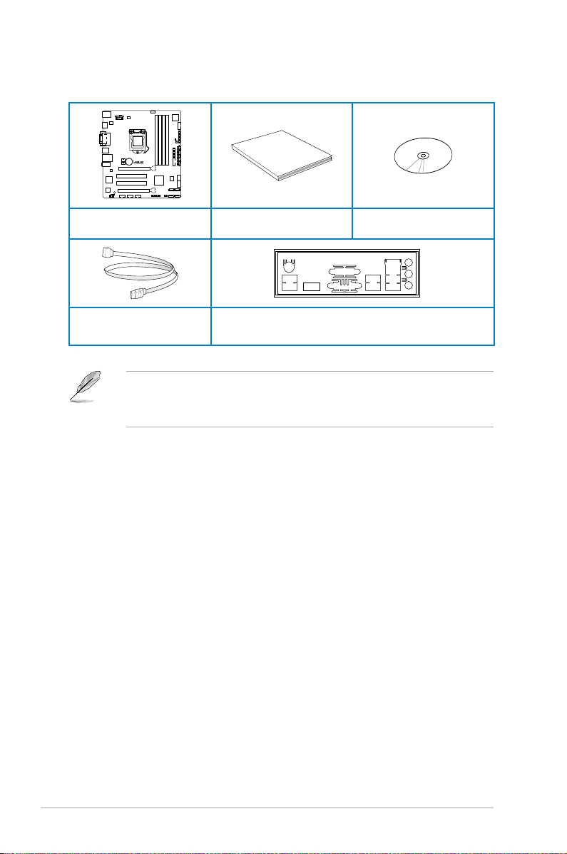
Check your motherboard package for the following items
ASUS H87M-PLUS motherboard
2 x Serial ATA 6.0 Gb/s cables 1 x ASUS I/O shield
User manual Support DVD
• If any of the above items is damaged or missing, contact your retailer.
• The illustrations above are for reference only. Actual product specications may vary
with different models.
xii
Page 13
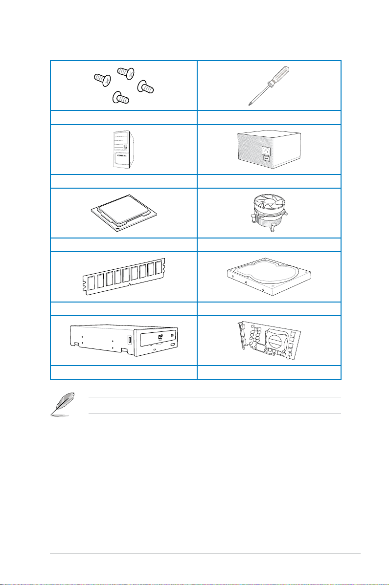
Installation tools and components
1 bag of screws Philips (cross) screwdriver
PC chassis Power supply unit
Intel® LGA1150 CPU Intel® LGA1150 compatible CPU Fan
DIMM SATA hard disk drive
SATA optical disc drive (optional) Graphics card (optional)
The tools and components in the table above are not included in the motherboard package.
xiii
Page 14

xiv
Page 15

Chapter 1: Product Introduction
Product introduction
1.1 Special features
1
1.1.1 Product highlights
LGA1150 socket for 4th Generation Intel® Core™ i7, Intel® Core™ i5, Intel®
Core™ i3, Pentium®, and Celeron® Processors
This motherboard supports Intel® 4th generation Core i7/i5/i3, Pentium®, and Celeron®
processors in the LGA1150 package. It provides great graphics and system performance with
its GPU, dual-channel DDR3 memory slots, and PCI Express 2.0/3.0 expansion slots.
Intel® H87 Express Chipset
Intel® H87 Express Chipset is a single-chipset that supports the 1150 socket 4th generation
Intel® Core™ i7, Intel® Core™ i5, Intel® Core™ i3, Pentium® and Celeron® processors. It
utilizes the serial point-to-point links, which increases bandwidth and enhances the system’s
performance. It natively supports up to six USB 3.0 ports for up to ten times faster transfer
rate than USB 2.0 and enables the iGPU function for Intel® integrated graphics performance.
PCI Express® 3.0
PCI Express® 3.0 (PCIe 3.0) is the PCI Express bus standard that provides twice the
performance and speed of PCIe 2.0. It provides an optimal graphics performance,
unprecedented data speed, and seamless transition with its complete backward compatibility
to PCIe 1.0/2.0 devices.
Dual-Channel DDR3 1600 / 1333 /1066MHz Support
The motherboard supports the dual-channel DDR3 memory that features data transfer rates
of DDR3 1600 / 1333 /1066MHz to boost the system’s performance, and to meet the higher
bandwidth requirements of 3D graphics, multimedia and Internet applications.
* Hyper DIMM support is subject to the physical characteristics of individual CPUs. Some hyper DIMMs only
support one DIMM per channel.
** Due to Intel
*** Refer to www.asus.com or this user manual for the Memory QVL (Qualied Vendors List)
Intel® Smart Response Technology
Intel® Smart Response Technology, an important part of Green ASUS eco-friendly computing,
reduces load and wait time, eliminates unecessary hard drive spin thus lowering power
usage, and uses an installed SSD (requires 18.6 GB available space) as a cache for
frequently accessed data or applications. It combines SSD performance and hard drive
capacity, operating up to six times faster than a hard-drive-only system to boost the system’s
overall performance.
* 4th generation Intel® Core™ processors support Intel® Smart Response Technology.
** An operating system must be installed on the HDD to launch Intel® Smart Response Technology.
*** The SSD is reserved for caching function.
®
maximum transfer rate of DDR3 1600MHz.
chipset limitation, DDR3 1600MHz and higher memory modules on XMP mode will run at the
Chapter 1
ASUS H87M-PLUS
1-1
Page 16

Quad-GPU CrossFireX™ Support
This motherboard features the most powerful Intel® H87 platform that optimizes PCIe
allocation in multi-GPU CrossFireX™ solution, giving you a brand-new gaming enjoyment.
Intel® Smart Connect Technology
Intel® Smart Connect Technology allows your system to receive updates for your web
applications in real-time even when your system is in sleep mode. This saves wait time for
applications to update and sync with the cloud for a more efcient computing experience.
Intel® Rapid Start Technology
Intel® Rapid Start Technology allows your computer to quickly resume from a low-power
hibernate state in seconds. Saving your system memory to the designated SSD, it provides
your computer a faster wake-up response time, while still keeping the energy use low.
1.1.2 5X Protection
5X Protection
ASUS motherboard guards your PC with 5X PROTECTION. We use components like
ESD uits tested to strict standards that elimiinate electrostatic interference, polyswitches
(resettable fuses) around DRAM slots to prevent overcurrent and short-circuit damage, and
a corrosion-resistant back I/O shield. All examples of ASUS providing the best possible
reliability and durability.
DIGI+VRM
Voltage regulator modules (VRMs) are among the most essential motherboard components.
A good VRM intelligently delivers CPU power based on actual needs at any given time.
Quickly-changing digital signal (SVID) requests from the CPU may prove too much for
generic VRMs, and ASUS was rst with digital controllers featuring faster sensing and
respnse to deliver precise CPU power on demand. This great accuracy reduces energy
waste and improves system stability.
ASUS DRAM Fuse
Onboard polyswitch (resettable fuse) prevents overcurrent and short-circuit damage. This
extends beyond I/O ports to DRAM to safeguard the system and device lifespan.
ASUS ESD Guards
Electrostatic discharges (ESD) can happen suddenly, and their damaging effects are often
underestimated. ASUS ESD Guards offer an active protective circuit design that ensures
electrostatic discharges are properly grounded, providing prolonged component longevity.
Chapter 1
ASUS High-Quality 5K Solid Capacitors
ASUS high-quality solid state capacitors assure a 5000-hour lifespan - equivalent to 2.5 times
longer than traditional capacitors. All capacitors pass testing under temperatures as high
as 105 degrees and meet Japanese industrial standards to provide excellent durability and
ehanced thermal capacity.
1-2
Chapter 1: Product introduction
Page 17

ASUS Stainless Steel Back I/O
ASUS motherboard back I/O panels are made from strong and corrosion-resistant stainless
steel, which is bonded with a thin layer of chromium oxide to enhance anti-corrosive
properties. Passing 72-hour spray salt endurance tests, ASUS stainless steel back I/O panels
have a usage life three times longer compared to ordinary panels.
1.1.3 ASUS Exclusive Features
ASUS EPU
Tap into the world’s rst real-time PC power saving chip through a simple onboard switch or
Ai Suite II utility. Get total system-wide energy optimization by automatically detecting current
PC loadings and intelligently moderating power consumption. This also reduces fan noise
and extends component longevity.
GPU Boost
GPU Boost accelerates the integrated GPU for extreme graphics performance, facilitates
exible frequency adjustments, and easily delivers stable system-level upgrades for every
use.
USB 3.0 Boost
ASUS USB 3.0 Boost, which supports USB 3.0 standard UASP (USB Attached SCSI
Protocol), signicantly increases a USB device’s transfer speed up to 170% faster than the
already impressive USB3.0 transfer speed. It automatically accelerates data speeds for
compatible USB 3.0 peripherals without the need for any user interaction.
Network iControl
Network iControl is an intuitive one-step network control center that makes it easier for you to
manage your bandwidth and allows you to set, monitor, and schedule the bandwidth priorities
for your network programs. It allows you to automatically connect to a PPPoE network for a
more convenient online experience.
ASUS H87M-PLUS
Chapter 1
1-3
Page 18

MemOK!
MemOK!, the remarkable memory rescue tool, allows you to simply press a button to
patch memory issues, ensure memory boot compatibility, determine fail-safe settings, and
dramatically improve the system’s bootup.
AI Suite 3
With its user-friendly interface, ASUS AI Suite 3 integrates several ASUS utilities and
allows you to launch and operate these utilities simultaneously. It allows you to congure
the overclocking settings, adjust the frequencies and related voltages, remotely control the
system via a mobile device, and other easy-to-use and helpful utilities.
ASUS Anti-Surge Protection
This special design protects expensive devices and the motherboard from damage caused
by power surges from switching power supply unit (PSU).
1.1.4 ASUS Quiet Thermal Solution
ASUS Fanless Design - Heat-pipe solution
The stylish heatsink features a 0-dB thermal solution that offers you a noiseless PC
environment. The heatsink design also lowers the temperature of the chipset and power
phase area through high efcient heat-exchange. Combined with usability and aesthetics,
the ASUS stylish heatsink will give you an extremely silent and cooling experience with its
elegant appearance.
ASUS Fan Xpert 2
ASUS Fan Xpert 2 provides customizable settings for a cooler and quieter computing
environment. With its Fan Auto Tuning feature, ASUS Fan Xpert 2 automatically detects
and tweaks all fan speeds, and provides you with optimized fan settings based on the fans’
specications and positions.
1.1.5 ASUS EZ DIY
ASUS UEFI BIOS
ASUS UEFI BIOS, a UEFI compliant architecture, offers the rst mouse-controlled intuitive
graphical BIOS interface that goes beyond the traditional keyboard-only BIOS controls,
providing you with more exibility, convenience, and easy to navigate UEFI BIOS than the
traditional BIOS versions. It offers you with dual selectable modes and native support for hard
drives larger than 2.2 TB.
ASUS UEFI BIOS includes the following new features:
• New My Favorite function allows you to quickly access the frequently used items
Chapter 1
• New Quick Note function allows you to take notes in the BIOS environment
• New log reminder allows you to view all your modied settings
1-4
Chapter 1: Product introduction
Page 19

• F12 BIOS snapshot hotkey
• F3 Shortcut for most accessed information
• ASUS DRAM SPD (Serial Presence Detect) information detecting faulty DIMMs, and
helping with difcult POST situations.
ASUS Q-Design
ASUS Q-Design enhances your DIY experience. All of Q-Slot and Q-DIMM design speed up
and simplify the DIY process.
1.1.6 Other special features
HDMI Support
High Denition Multimedia Surface (HDMI) is a set of digital video standards that delivers
multi-channel audio and uncompressed digital video for full HD 1080p visuals through a
single cable. Supporting HDCP copy protection such as HD DVD and blu-ray discs, HDMI
provides you with the highest quality home theater experience.
ErP Ready
The motherboard is European Union’s Energy-related Products (ErP) ready, and ErP requires
products to meet certain energy efciency requirement in regards to energy consumptions.
This is in line with ASUS vision of creating environment-friendly and energy-efcient products
through product design and innovation to reduce carbon footprint of the product and thus
mitigate environmental impacts.
1.2 Motherboard overview
1.2.1 Before you proceed
Take note of the following precautions before you install motherboard components or change
any motherboard settings.
• Unplug the power cord from the wall socket before touching any component.
• Before handling components, use a grounded wrist strap or touch a safely grounded
object or a metal object, such as the power supply case, to avoid damaging them due
to static electricity.
• Hold components by the edges to avoid touching the ICs on them.
• Whenever you uninstall any component, place it on a grounded antistatic pad or in the
bag that came with the component.
• Before you install or remove any component, ensure that the ATX power supply is
switched off or the power cord is detached from the power supply. Failure to do so
may cause severe damage to the motherboard, peripherals, or components.
ASUS H87M-PLUS
Chapter 1
1-5
Page 20
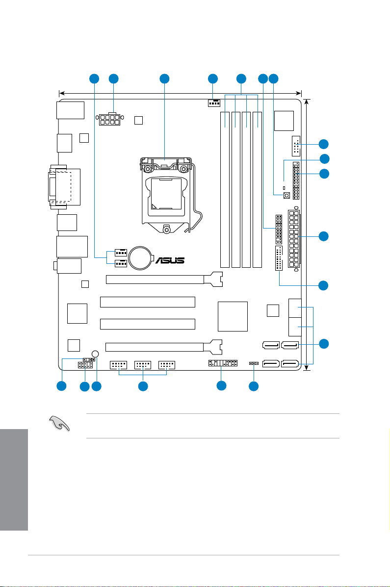
1.2.2 Motherboard layout
H87M-PLUS
PCIEX16_1
PCIEX16_2
PCI1
PCI2
RTL
8111G
ASM
1442
USB910 USB1112 USB1314
AAFP
EATXPWR
CPU_FAN
BATTERY
Super
I/O
ALC
887
ASM
1083
KBMS_USB78
DVI_VGA
8MB
BIOS
SB_PWR
CLRTC
21.9cm(8.6in)
DDR3 DIMM_A1 (64bit, 240-pin module)
DDR3 DIMM_A2 (64bit, 240-pin module)
DDR3 DIMM_B1 (64bit, 240-pin module)
DDR3 DIMM_B2 (64bit, 240-pin module)
PANEL
SATA6G_1SATA6G_2
SATA6G_3 SATA6G_4
SATA6G_5 SATA6G_6
AUDIO
LAN_USB3_34
USB3_56
HDMI
CHA_FAN2
CHA_FAN1
SPDIF_OUT
24.4cm(9.6in)
DRAM_LED
MemOK!
LGA1150
DIGI
+VRM
COM
EATX12V
USB3_12
TPM
LPT
Intel
®
H87
21 3 41 65
1215
11
13
14
16
8
7
2
9
10
17
Chapter 1
1-6
Refer to 1.2.9 Internal connectors and 2.2.1 Rear I/O connection for more information
about rear panel connectors and internal connectors.
Chapter 1: Product introduction
Page 21

Layout contents
Connectors/Jumpers/Slots Page
1. CPU and chassis fan connectors (4-pin CPU_FAN, 4-pin CHA_FAN1/2) 1-19
2. ATX power connectors (24-pin EATXPWR, 8-pin EATX12V)
3. LGA1150 CPU socket
4. DDR3 DIMM slots
5. TPM header (20-1 pin TPM)
6. MemOK! button
7. Serial port connector (10-1 pin COM)
8. DRAM LED (DRAM_LED)
9. LPT connector (26-1 pin LPT)
10. USB 3.0 connector (20-1 pin USB3_12)
®
11. Intel
12. Clear RTC RAM (3-pin CLRTC)
13. System panel connector (20-8 pin PANEL)
14. USB 2.0 connectors (10-1 pin USB910, USB1112, USB1314)
15. Standby power LED (SB_PWR)
16. Front panel audio connector (10-1 pin AAFP)
17. Digital audio connector (4-1 pin SPDIF_OUT)
H87 Serial ATA 6.0 Gb/s connectors (7-pin SATA6G_1-6) 1-16
1-20
1-8
1-9
1-20
1-14
1-17
1-15
1-16
1-17
1-13
1-21
1-18
1-15
1-19
1-18
ASUS H87M-PLUS
Chapter 1
1-7
Page 22
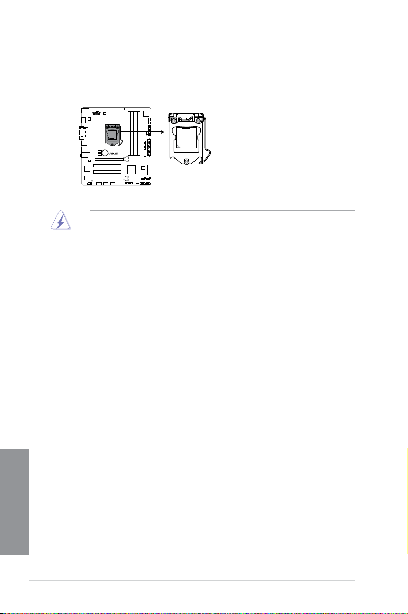
1.2.3 Central Processing Unit (CPU)
H87M-PLUS
H87M-PLUS CPU socket LGA1150
The motherboard comes with a surface mount LGA1150 socket designed for the 4th
Generation Intel® Core™ i7, Intel® Core™ i5, Intel® Core™ i3, Pentium™, and Celeron™
processors.
• Ensure that all power cables are unplugged before installing the CPU.
• Ensure that you install the correct CPU designed for LGA1150 only. DO NOT install a
CPU designed for LGA1155 and LGA1156 sockets on the LGA1150 socket.
• Upon purchase of the motherboard, ensure that the PnP cap is on the socket and
the socket contacts are not bent. Contact your retailer immediately if the PnP cap
is missing, or if you see any damage to the PnP cap/socket contacts/motherboard
components. ASUS will shoulder the cost of repair only if the damage is shipment/
transit-related.
• Keep the cap after installing the motherboard. ASUS will process Return Merchandise
Authorization (RMA) requests only if the motherboard comes with the cap on the
LGA1150 socket.
• The product warranty does not cover damage to the socket contacts resulting from
incorrect CPU installation/removal, or misplacement/loss/incorrect removal of the PnP
cap.
Chapter 1
1-8
Chapter 1: Product introduction
Page 23
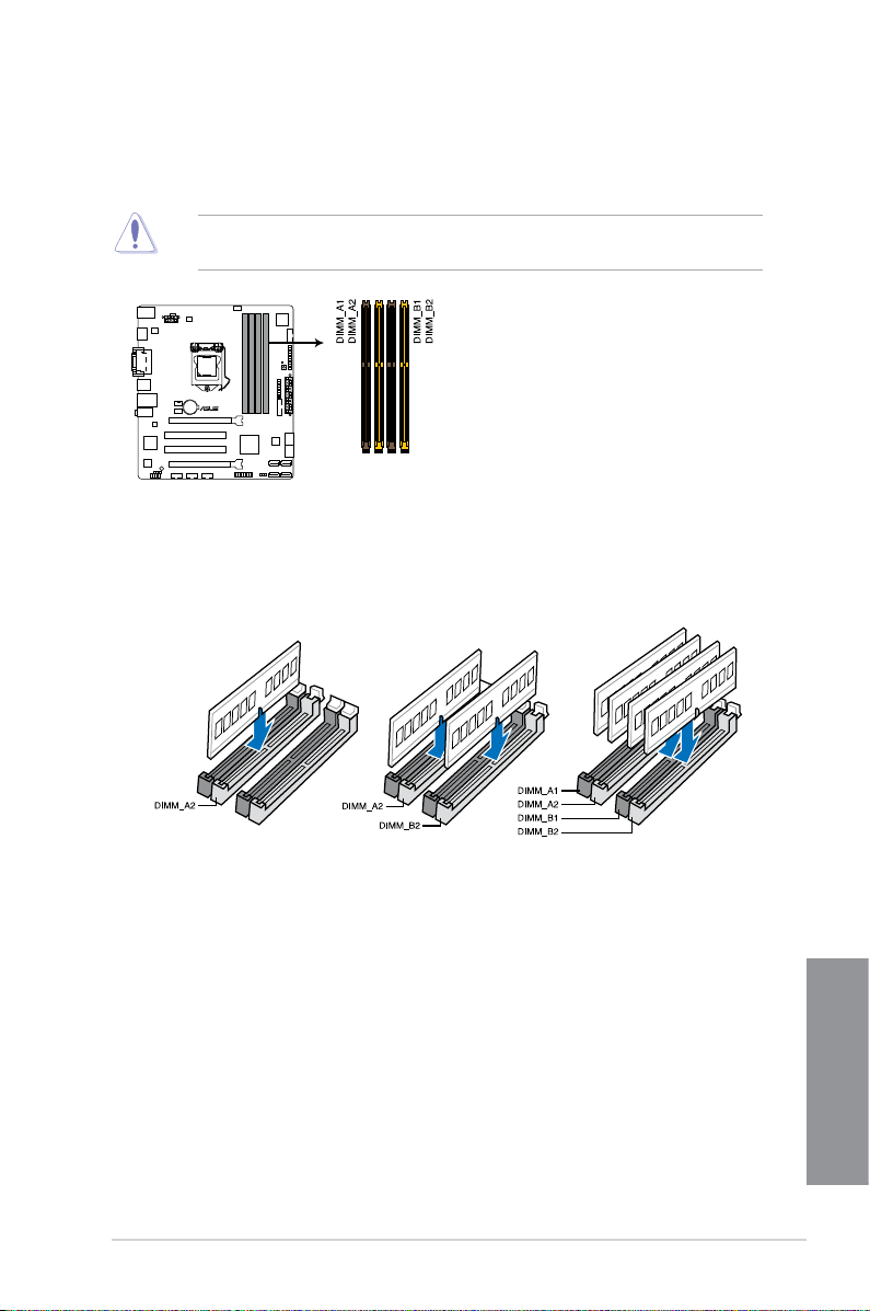
1.2.4 System memory
H87M-PLUS
H87M-PLUS 240-pin DDR3 DIMM sockets
The motherboard comes with four Double Data Rate 3 (DDR3) Dual Inline Memory Modules
(DIMM) slots.
A DDR3 module is notched differently from a DDR or DDR2 module. DO NOT install a DDR
or DDR2 memory module to the DDR3 slot.
Recommended memory congurations
ASUS H87M-PLUS
Chapter 1
1-9
Page 24

Memory congurations
You may install 1GB, 2GB, 4GB, and 8GB unbuffered and non-ECC DDR3 DIMMs into the
DIMM sockets.
Chapter 1
• You may install varying memory sizes in Channel A and Channel B. The system maps
the total size of the lower-sized channel for the dual-channel conguration. Any excess
memory from the higher-sized channel is then mapped for single-channel operation.
• Due to Intel
®
chipset limitation, DDR3 1600MHz and higher memory modules on XMP
mode will run at the maximum transfer rate of DDR3 1600MHz.
• According to Intel CPU spec, DIMM voltage below 1.65V is recommended to protect
the CPU.
• Always install DIMMs with the same CAS latency. For optimum compatibility, we
recommend that you obtain memory modules from the same vendor.
• Due to the memory address limitation on 32-bit Windows
®
OS, when you install 4GB
or more memory on the motherboard, the actual usable memory for the OS can be
about 3GB or less. For effective use of memory, we recommend that you do any of the
following:
a) Use a maximum of 3GB system memory if you are using a 32-bit Windows
b) Install a 64-bit Windows
®
OS when you want to install 4GB or more on the
®
OS.
motherboard.
c) For more details, refer to the Microsoft
®
support site at http://support.microsoft.
com/kb/929605/en-us.
• This motherboard does not support DIMMs made up of 512Mb (64MB) chips or less
(Memory chip capacity counts in Megabit, 8 Megabit/Mb = 1 Megabyte/MB).
• The default memory operation frequency is dependent on its Serial Presence Detect
(SPD), which is the standard way of accessing information from a memory module.
Under the default state, some memory modules for overclocking may operate at a
lower frequency than the vendor-marked value. To operate at the vendor-marked
or at a higher frequency, refer to section 3.5 Ai Tweaker menu for manual memory
frequency adjustment.
• For system stability, use a more efcient memory cooling system to support a full
memory load (4 DIMMs) or overclocking condition.
• Memory modules with memory frequency higher than 2133MHz and their
corresponding timing or the loaded XMP prole is not the JEDEC memory standard.
The stability and compatibility of the memory modules depend on the CPU’s
capabilities and other installed devices.
• Always install the DIMMS with the same CAS Latency. For an optimum compatibility,
we recommend that you install memory modules of the same version or data code (D/
C) from the same vendor. Check with the vendor to get the correct memory modules.
• ASUS exclusively provides hyper DIMM support function.
• Hyper DIMM support is subject to the physical characteristics of individual CPUs. Load
the X.M.P. or D.O.C.P. settings in the BIOS for the hyper DIMM support.
• Visit the ASUS website for the latest QVL.
1-10
Chapter 1: Product introduction
Page 25
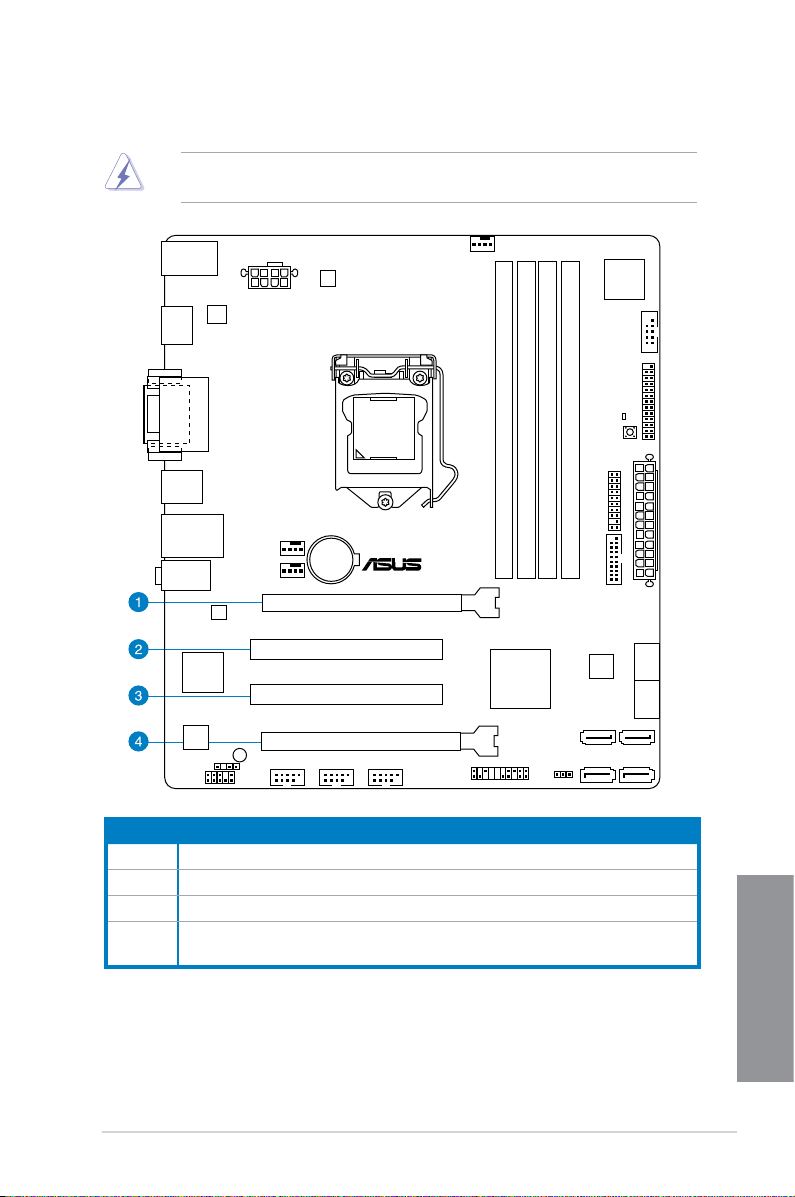
1.2.5 Expansion slots
H87M-PLUS
PCIEX16_1
PCIEX16_2
PCI1
PCI2
EATX12V
Unplug the power cord before adding or removing expansion cards. Failure to do so may
cause you physical injury and damage motherboard components.
Slot No. Slot Description
1 PCIe 3.0/2.0 x16_1 slot (at x16 mode)
2 PCI_1 slot
3 PCI_2 slot
4 PCIe 2.0 x16_2 slot (run at x4 mode, compatible with PCIe x1 and x4 devices)
ASUS H87M-PLUS
Chapter 1
1-11
Page 26
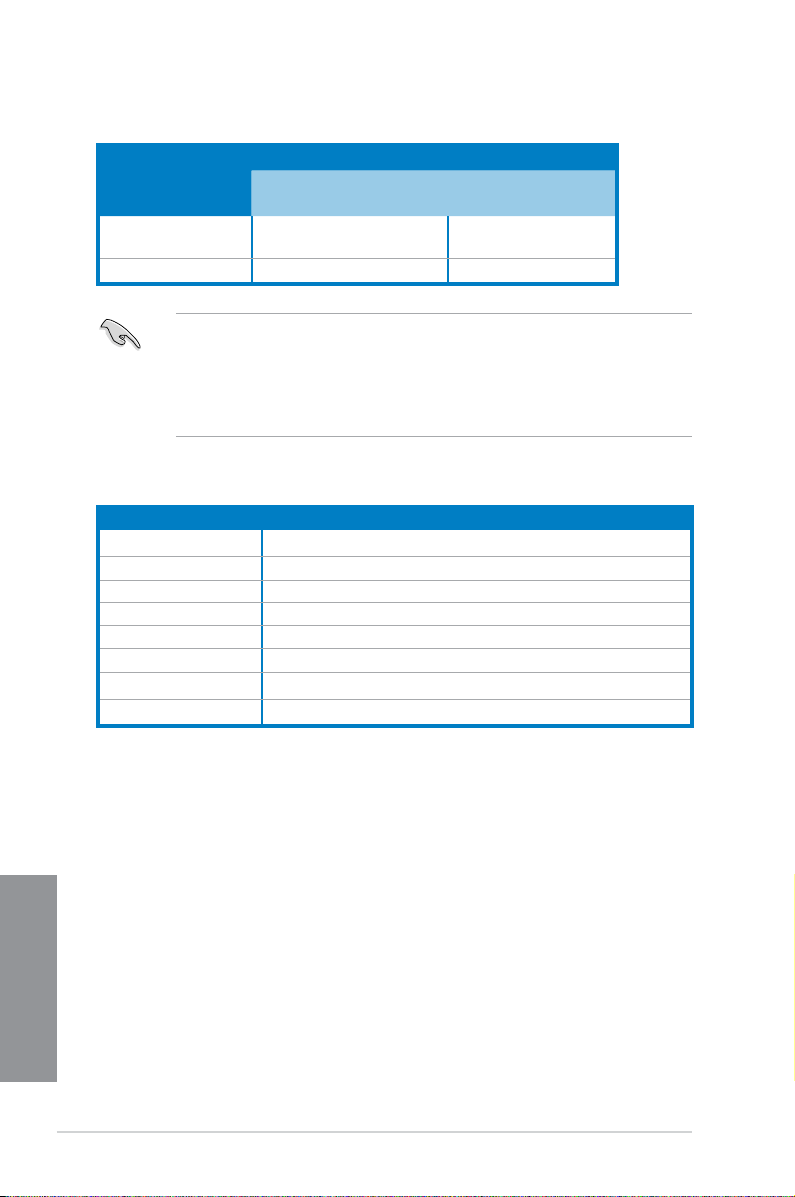
PCIe Express operating mode
VGA conguration
Single VGA/PCIe card x16 (single VGA recommended) N/A
Dual VGA/PCIe card x16 x4
• In single VGA card mode, use the PCIe 3.0/2.0 x16_1 slot (yellow) for a PCI Express
x16 graphics card to get better performance.
• We recommend that you provide sufcient power when running CrossFireX™ mode.
• Connect a chassis fan to the motherboard connector labeled CHA_FAN1/2 when
using multiple graphics cards for better thermal environment.
PCIe 3.0/2.0 x16_1 PCIe 2.0 x16_2
IRQ assignments for this motherboard
A B C D E F G H
PCIe x16_1 shared – – – – – – –
PCIe x16_2 shared – – – – – – –
Intel SATA Controller – – – shared – – – –
Realtek LAN – – shared – – – – –
Intel xHCI – – – – – shared – –
Intel EHCI 1 – – – – – – – shared
Intel EHCI 2 – – – – shared – – –
HD Audio – – – – – – shared –
Chapter 1
1-12
Chapter 1: Product introduction
Page 27
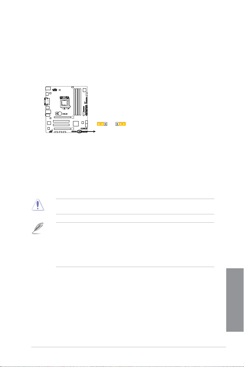
1.2.6 Jumpers
H87M-PLUS
H87M-PLUS Clear RTC RAM
2 2 3
Normal
(Default)
Clear RTC
CLRTC
Clear RTC RAM (3-pin CLRTC)
This jumper allows you to clear the Real Time Clock (RTC) RAM in CMOS. You can clear the
CMOS memory of date, time, and system setup parameters by erasing the CMOS RTC RAM
data. The onboard button cell battery powers the RAM data in CMOS, which include system
setup information such as system passwords.
To erase the RTC RAM:
1. Turn OFF the computer and unplug the power cord.
2. Move the jumper cap from pins 1-2 (default) to pins 2-3. Keep the cap on pins 2-3 for
about 5~10 seconds, then move the cap back to pins 1-2.
3. Plug the power cord and turn ON the computer.
4. Hold down the
data.
<Del> key during the boot process and enter BIOS setup to reenter
Except when clearing the RTC RAM, never remove the cap on CLRTC jumper default
position. Removing the cap will cause system boot failure!
• If the steps above do not help, remove the onboard battery and move the jumper
• You do not need to clear the RTC when the system hangs due to overclocking. For
ASUS H87M-PLUS
again to clear the CMOS RTC RAM data. After clearing the CMOS, reinstall the
battery.
system failure due to overclocking, use the CPU Parameter Recall (C.P.R) feature.
Shut down and reboot the system so the BIOS can automatically reset parameter
settings to default values.
Chapter 1
1-13
Page 28
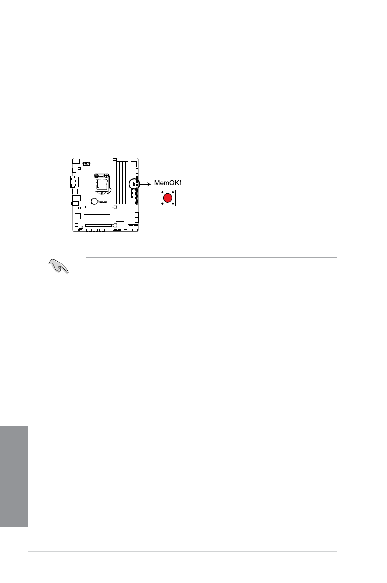
1.2.7 Onboard buttons and switches
H87M-PLUS
H87M-PLUS MemOK! switch
Onboard switches and buttons allow you to ne-tune performance when working on a bare or
open-case system. This is ideal for overclockers and gamers who continually change settings
to enhance system performance.
1. MemOK! button
Installing DIMMs that are not compatible with the motherboard may cause system
boot failure, and the DRAM_LED near the MemOK! switch lights continuously. Press
and hold the MemOK! button until the DRAM_LED starts blinking to begin automatic
memory compatibility tuning for successful boot.
Chapter 1
• Refer to section 1.2.8 Onboard LEDs for the exact location of the DRAM_LED.
• The DRAM_LED also lights up when the DIMM is not properly installed. Turn off the
system and reinstall the DIMM before using the MemOK! function.
• The MemOK! switch does not function under Windows
• During the tuning process, the system loads and tests failsafe memory settings. It
takes about 30 seconds for the system to test one set of failsafe settings. If the test
fails, the system reboots and test the next set of failsafe settings. The blinking speed
of the DRAM_LED increases, indicating different test processes.
• Due to memory tuning requirement, the system automatically reboots when each
timing set is tested. If the installed DIMMs still fail to boot after the whole tuning
process, the DRAM_LED lights continuously. Replace the DIMMs with ones
recommended in the Memory QVL (Qualied Vendors Lists) in this user manual or on
the ASUS website at www.asus.com.
• If you turn off the computer and replace DIMMs during the tuning process, the system
continues memory tuning after turning on the computer. To stop memory tuning, turn
off the computer and unplug the power cord for about 5–10 seconds.
• If your system fails to boot up due to BIOS overclocking, press the MemOK! switch
to boot and load the BIOS default settings. A message will appear during POST
reminding you that the BIOS has been restored to its default settings.
• We recommend that you download and update to the latest BIOS version from the
ASUS website at www.asus.com after using the MemOK! function.
®
OS environment.
1-14
Chapter 1: Product introduction
Page 29
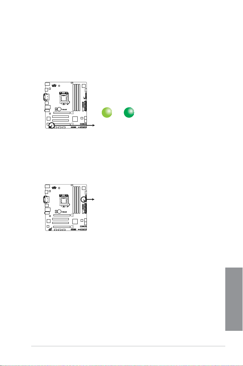
1.2.8 Onboard LEDs
SB_PWR
ON
Standby Power
Powered Off
OFF
H87M-PLUS
H87M-PLUS Onboard LED
H87M-PLUS
H87M-PLUS DRAM LED
DRAM LED
1. Standby Power LED
The motherboard comes with a standby power LED that lights up to indicate that the
system is ON, in sleep mode, or in soft-off mode. This is a reminder that you should
shut down the system and unplug the power cable before removing or plugging in any
motherboard component. The illustration below shows the location of the onboard LED.
2. DRAM LED
DRAM LED checks the DRAM in sequence during motherboard booting process. If an
error is found , the LED next to the error device will continue lighting until the problem
is solved. This user-friendly design provides an intuitional way to locate the root
problem within a second.
ASUS H87M-PLUS
Chapter 1
1-15
Page 30
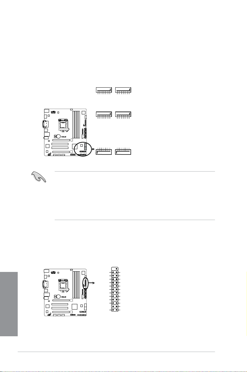
1.2.9 Internal connectors
SATA6G_5
GND
RSATA_RXP5
RSATA_RXN5
GND
RSATA_TXN5
RSATA_TXP5
GND
SATA6G_6
GND
RSATA_RXP6
RSATA_RXN6
GND
RSATA_TXN6
RSATA_TXP6
GND
H87M-PLUS
H87M-PLUS SATA 6.0Gb/s connectors
GND
RSATA_TXP3
RSATA_TXN3
GND
RSATA_RXN3
RSATA_RXP3
GND
SATA6G_4SATA6G_3
GND
RSATA_TXP4
RSATA_TXN4
GND
RSATA_RXN4
RSATA_RXP4
GND
GND
RSATA_TXP1
RSATA_TXN1
GND
RSATA_RXN1
RSATA_RXP1
GND
SATA6G_2SATA6G_1
GND
RSATA_TXP2
RSATA_TXN2
GND
RSATA_RXN2
RSATA_RXP2
GND
H87M-PLUS
H87M-PLUS Parallel Port Connector
LPT
PIN 1
SLCT
PE
BUSY
ACK#
PD7
PD6
PD5
PD4
PD3
PD2
PD1
PD0
STB#
GND
GND
GND
GND
GND
GND
GND
GND
SLIN#
INIT#
ERR#
AFD
1. Intel® H87 Serial ATA 6.0 Gb/s connectors (7-pin SATA6G_1-6)
These connectors connect to Serial ATA 6.0 Gb/s hard disk drives via Serial ATA 6.0
Gb/s signal cables.
If you installed Serial ATA hard disk drives, you can create a RAID 0, 1, 5, and 10
conguration with the Intel® Rapid Storage Technology through the onboard Intel® H87
chipset.
• These connectors are set to [AHCI Mode] by default. If you intend to create a Serial
ATA RAID set using these connectors, set the SATA Mode item in the BIOS to [RAID
Mode]. Refer to section 3.6.3 SATA Conguration for details.
• Before creating a RAID set, refer to section
bundled in the motherboard support DVD.
• When using hot-plug and NCQ, set the type of the SATA connectors in the BIOS to
[AHCI]. See section 3.6.3 SATA Conguration for details.
5.1 RAID congurations or the manual
2. LPT connector (26-1 pin LPT)
The LPT (Line Printing Terminal) connector supports devices such as a printer. LPT
standardizes as IEEE 1284, which is the parallel port interface on IBM PC-compatible
computers.
Chapter 1
1-16
Chapter 1: Product introduction
Page 31

3. USB 3.0 connector (20-1 pin USB3_12)
H87M-PLUS
H87M-PLUS USB3.0 Front panel connector
USB3_12
H87M-PLUS
H87M-PLUS Serial port (COM) connector
PIN 1
COM
RI
RTS
GND
TXD
DCD
CTS
DSR
DTR
RXD
This connector allows you to connect a USB 3.0 module for additional USB 3.0 front
or rear panel ports. With an installed USB 3.0 module, you can enjoy all the benets of
USB 3.0 including faster data transfer speeds of up to 5Gbps, faster charging time for
USB-chargeable devices, optimized power efciency, and backward compatibility with
USB 2.0.
• The USB 3.0 module is purchased separately.
• These connectors are based on xHCI specication. We recommend you to install
the related driver to fully use the USB 3.0 ports under Windows® 7 or later operating
systems.
4. Serial port connector (10-1 pin COM)
This connector is for a serial (COM) port. Connect the serial port module cable to this
connector, then install the module to a slot opening at the back of the system chassis.
The COM module is purchased separately.
ASUS H87M-PLUS
Chapter 1
1-17
Page 32

H87M-PLUS
H87M-PLUS Digital audio connector
SPDIF_OUT
+5V
SPDIFOUT
GND
5. USB 2.0 connectors (10-1 pin USB910; USB1112; USB1314)
H87M-PLUS
H87M-PLUS USB2.0 connectors
USB+5V
USB_P13-
USB_P13+
GND
NC
USB+5V
USB_P14-
USB_P14+
GND
USB1314
PIN 1
USB+5V
USB_P9-
USB_P9+
GND
NC
USB+5V
USB_P10-
USB_P10+
GND
USB910
PIN 1
USB+5V
USB_P11-
USB_P11+
GND
NC
USB+5V
USB_P12-
USB_P12+
GND
USB1112
PIN 1
These connectors are for USB 2.0 ports. Connect the USB module cable to any of
these connectors, then install the module to a slot opening at the back of the system
chassis. These USB connectors comply with USB 2.0 specication that supports up to
480Mbps connection speed.
Never connect a 1394 cable to the USB connectors. Doing so will damage the
motherboard!
• The USB 2.0 module is purchased separately.
• These connectors are based on xHCI specication. We recommend you to install
the related driver to fully use the USB 2.0 ports under Windows® 7 or later operating
systems.
6. Digital audio connector (4-1 pin SPDIF_OUT)
This connector is for an additional Sony/Philips Digital Interface (S/PDIF) port. Connect
the S/PDIF Out module cable to this connector, then install the module to a slot
opening at the back of the system chassis.
Chapter 1
The S/PDIF module is purchased separately.
1-18
Chapter 1: Product introduction
Page 33

7. CPU and chassis fan connectors (4-pin CPU_FAN; 4-pin CHA_FAN1/2)
CHA_FAN2
CHA FAN PWM
CHA FAN IN
CHA FAN PWR
GND
CHA_FAN1
CHA FAN PWM
CHA FAN IN
CHA FAN PWR
GND
CPU_FAN
CPU FAN PWM
CPU FAN IN
CPU FAN PWR
GND
H87M-PLUS
H87M-PLUS Fan connectors
1
1
2
3
2
3
H87M-PLUS
H87M-PLUS Front panel audio connector
AAFP
AGNDNCSENSE1_RETUR
SENSE2_RETUR
PORT1 L
PORT1 R
PORT2 R
SENSE_SEND
PORT2 L
HD-audio-compliant
pin definition
PIN 1
AGNDNCNC
NC
MIC2
MICPWR
Line out_R
NC
Line out_L
Legacy AC’97
compliant definition
Connect the fan cables to the fan connectors on the motherboard, ensuring that the
black wire of each cable matches the ground pin of the connector.
DO NOT forget to connect the fan cables to the fan connectors. Insufcient air ow inside
the system may damage the motherboard components. These are not jumpers! Do not
place jumper caps on the fan connectors!
• The CPU_FAN connector supports the CPU fan of maximum 1A (12 W) fan power.
• Only 4-pin CPU fans and chassis fans support the ASUS FAN Xpert 2 feature.
8. Front panel audio connector (10-1 pin AAFP)
This connector is for a chassis-mounted front panel audio I/O module that supports
either HD Audio or legacy AC`97 audio standard. Connect one end of the front panel
audio I/O module cable to this connector.
• We recommend that you connect a high-denition front panel audio module to this
connector to avail of the motherboard’s high-denition audio capability.
• If you want to connect a high-denition or an AC’97 front panel audio module to this
ASUS H87M-PLUS
connector, set the Front Panel Type item in the BIOS setup to [HD] or [AC97].
Chapter 1
1-19
Page 34

9. ATX power connectors (24-pin EATXPWR; 8-pin EATX12V)
H87M-PLUS
H87M-PLUS ATX power connectors
EATXPWR
PIN 1
GND
+5 Volts
+5 Volts
+5 Volts
-5 Volts
GND
GND
GND
PSON#
GND
-12 Volts
+3 Volts
+3 Volts
+12 Volts
+12 Volts
+5V Standby
Power OK
GND
+5 Volts
GND
+5 Volts
GND
+3 Volts
+3 Volts
EATX12V
PIN 1
+12V DC
+12V DC
+12V DC
+12V DC
GND
GND
GND
GND
H87M-PLUS
H87M-PLUS TPM Connector
PIN 1
TPM
SB_SUS_STAT
GND
+3VSB
SMBSCL
LAD0
+3V
LAD3
PCIRST#
FRAME
PCICLK
RESET
GPIO
SERIRQ
SMBSDA
GND
LAD1
LAD2
PWROWN
GND
These connectors are for ATX power supply plugs. The power supply plugs are
designed to t these connectors in only one orientation. Find the proper orientation and
push down rmly until the connectors completely t.
• For a fully congured system, we recommend that you use a power supply unit
(PSU) that complies with ATX 12V Specication 2.0 (or later version) and provides a
minimum power of 350W.
• DO NOT forget to connect the 4-pin/8-pin EATX12V power plug. Otherwise, the
system will not boot.
• We recommend that you use a PSU with a higher power output when conguring a
system with more power-consuming devices. The system may become unstable or
may not boot up if the power is inadequate.
• If you want to use two high-end PCI Express x16 cards, use a PSU with 1000W power
or above to ensure the system stability.
• If you are uncertain about the minimum power supply requirement for your system,
refer to the Recommended Power Supply Wattage Calculator at http://support.asus.
com/PowerSupplyCalculator/PSCalculator.aspx?SLanguage=en-us for details.
10. TPM connector (20-1 pin TPM)
This connector supports a Trusted Platform Module (TPM) system, which securely
store keys, digital certicates, passwords and data. A TPM system also helps enhance
network security, protect digital identities, and ensures platform integrity.
Chapter 1
The TPM module is purchased separately.
1-20
Chapter 1: Product introduction
Page 35

11. System panel connector (20-8 pin PANEL)
H87M-PLUS
H87M-PLUS System panel connector
PIN 1
* Requires an ATX power supply
PWR_LED
SPEAKER
PWR_LED+
PWR_LED-
+5V
Ground
Ground
Speaker
HDD_LED+
HDD_LED-
PWR
Ground
Reset
Ground
PANEL
HDD_LED
PWR_SW
RESET
This connector supports several chassis-mounted functions.
• System power LED (2-pin PWR_LED)
This 2-pin connector is for the system power LED. Connect the chassis power LED
cable to this connector. The system power LED lights up when you turn on the system
power, and blinks when the system is in sleep mode.
• Hard disk drive activity LED (2-pin HDD_LED)
This 2-pin connector is for the HDD Activity LED. Connect the HDD Activity LED cable
to this connector. The HDD LED lights up or ashes when data is read from or written
to the HDD.
• System warning speaker (4-pin SPEAKER)
This 4-pin connector is for the chassis-mounted system warning speaker. The speaker
allows you to hear system beeps and warnings.
• ATX power button/soft-off button (2-pin PWR_SW)
This connector is for the system power button. Pressing the power button turns the
system on or puts the system in sleep or soft-off mode depending on the operating
system settings. Pressing the power switch for more than four seconds while the
system is ON turns the system OFF.
• Reset button (2-pin RESET)
This 2-pin connector is for the chassis-mounted reset button for system reboot without
turning off the system power.
ASUS H87M-PLUS
Chapter 1
1-21
Page 36

Chapter 1
1-22
Chapter 1: Product introduction
Page 37

Chapter 2: Basic installation
Basic installation
2.1 Building your PC system
2.1.1 Motherboard installation
The diagrams in this section are for reference only. The motherboard layout may vary with
models, but the installation steps are the same for all models.
1. Install the ASUS I/O shield to the chassis rear I/O panel.
2
2. Place the motherboard into the chassis, ensuring that its rear I/O ports are aligned to
the chassis’ rear I/O panel.
ASUS H87M-PLUS
Chapter 2
2-1
Page 38

3. Place six screws into the holes indicated by circles to secure the motherboard to the
H87M-PLUS
chassis.
Chapter 2
2-2
DO NOT overtighten the screws! Doing so can damage the motherboard.
Chapter 2: Basic installation
Page 39

2.1.2 CPU installation
Ensure that you install the correct CPU designed for LGA1150 socket only. DO NOT install
a CPU designed for LGA1155 and LGA1156 socket on the LGA1150 socket.
ASUS H87M-PLUS
Chapter 2
2-3
Page 40

2.1.3 CPU heatsink and fan assembly installation
Apply the Thermal Interface Material to the
CPU heatsink and CPU before you install
the heatsink and fan, if necessary.
To install the CPU heatsink and fan assembly
Chapter 2
2-4
Chapter 2: Basic installation
Page 41

To uninstall the CPU heatsink and fan assembly
ASUS H87M-PLUS
Chapter 2
2-5
Page 42

2.1.4 DIMM installation
To remove a DIMM
Chapter 2
2-6
Chapter 2: Basic installation
Page 43

2.1.5 ATX Power connection
OR
ASUS H87M-PLUS
Chapter 2
2-7
Page 44

2.1.6 SATA device connection
OR
OR
Chapter 2
2-8
Chapter 2: Basic installation
Page 45

2.1.7 Front I/O Connector
HDD_LED
To install the system panel connector
To install USB 2.0 connector To install front panel audio connector
AAFP
USB 2.0
To install USB 3.0 connector
USB 3.0
ASUS H87M-PLUS
Chapter 2
2-9
Page 46

2.1.8 Expansion Card installation
To install PCIe x16 cards
To install PCI cards
Chapter 2
2-10
Chapter 2: Basic installation
Page 47

2.2 Motherboard rear and audio connections
2.2.1 Rear I/O connection
Rear panel connectors
1. PS/2 keyboard / mouse combo
port
2. Video Graphics Adapter (VGA)
port
®
3. Realtek
LAN (RJ-45) port* 7. HDMI port
4. Audio I/O ports** 8. USB 2.0 ports 7 and 8
* and **: Refer to the tables on the next page for LAN port LEDs, and audio port denitions.
5. Intel USB 3.0 ports 3-6, support ASUS
USB 3.0 Boost
6. DVI port
• Due to USB 3.0 controller limitation, USB 3.0 devices can only be used under
Windows® OS environment and after the USB 3.0 driver installation.
• USB 3.0 devices can only be used as data storage only.
• We strongly recommend that you connect USB 3.0 devices to USB 3.0 ports for faster
and better performance for your USB 3.0 devices.
• Due to the design of the Intel
USB 2.0 and USB 3.0 ports are controlled by the xHCI controller. Some legacy USB
devices must update their rmware for better compatibility.
• Multi-VGA output supports up to three displays under a Windows
two displays under BIOS, and one display under DOS.
• Intel
clocks (Pixel Clock = H total x V total x Frame Rate (Screen refresh rate):
ASUS H87M-PLUS
®
8 series chipset, all USB devices connected to the
®
OS environment,
®
display architecture design supports the following maximum supported pixel
- DVI port: 165 MHz
- VGA port: 180 MHz
- HDMI port: 300 MHz
Chapter 2
2-11
Page 48

* LAN ports LED indications
Speed LED
Status Description
OFF 10 Mbps connection
ORANGE 100 Mbps connection
GREEN 1 Gbps connection
Activity Link LED
Status Description
OFF No link
ORANGE Linked
BLINKING Data activity
ORANGE
(Blinking then steady)
Ready to wake up from S5
mode
** Audio 2, 4, 6, or 8-channel conguration
ACT/LINK
LED
LAN port
SPEED
LED
Light Blue (Rear
panel)
Lime (Rear panel) Line Out Front Speaker Out
Pink (Rear panel) Mic In Mic In Bass/Center Bass/Center
Lime (Front panel) - - - Side Speaker Out
Chapter 2
Port
To congure an 8-channel audio output:
Use a chassis with HD audio module in the front panel to support an 8-channel audio
Headset
2-channel
4-channel 6-channel 8-channel
Line In Rear Speaker Out
output.
Rear Speaker
Out
Front Speaker
Out
Rear Speaker
Out
Front Speaker
Out
2-12
Chapter 2: Basic installation
Page 49

2.2.2 Audio I/O connections
Audio I/O ports
Connect to Headphone and Mic
Connect to Stereo Speakers
Connect to 2.1 channel Speakers
ASUS H87M-PLUS
Chapter 2
2-13
Page 50

Connect to 4.1 channel Speakers
Connect to 5.1 channel Speakers
Connect to 7.1 channel Speakers
Chapter 2
2-14
Chapter 2: Basic installation
Page 51

2.3 Starting up for the rst time
1. After making all the connections, replace the system case cover.
2. Ensure that all switches are off.
3. Connect the power cord to the power connector at the back of the system chassis.
4. Connect the power cord to a power outlet that is equipped with a surge protector.
5. Turn on the devices in the following order:
a. Monitor
b. External SCSI devices (starting with the last device on the chain)
c. System power
6. After applying power, the system power LED on the system front panel case lights up.
For systems with ATX power supplies, the system LED lights up when you press the
ATX power button. If your monitor complies with the “green” standards or if it has a
“power standby” feature, the monitor LED may light up or change from orange to green
after the system LED turns on.
The system then runs the power-on self tests (POST). While the tests are running, the
BIOS beeps (refer to the BIOS beep codes table) or additional messages appear on
the screen. If you do not see anything within 30 seconds from the time you turned on
the power, the system may have failed a power-on test. Check the jumper settings and
connections or call your retailer for assistance.
BIOS Beep Description
One short beep VGA detected
Quick boot set to disabled
No keyboard detected
One continuous beep followed by two
short beeps then a pause (repeated)
One continuous beep followed by three
short beeps
One continuous beep followed by four
short beeps
No memory detected
No VGA detected
Hardware component failure
7. At power on, hold down the <Delete> key to enter the BIOS Setup. Follow the
instructions in Chapter 3.
2.4 Turning off the computer
While the system is ON, press the power button for less than four seconds to put the system
on sleep mode or soft-off mode, depending on the BIOS setting. Press the power switch
for more than four seconds to let the system enter the soft-off mode regardless of the BIOS
setting.
ASUS H87M-PLUS
Chapter 2
2-15
Page 52

Chapter 2
2-16
Chapter 2: Basic installation
Page 53

Chapter 3: BIOS setup
BIOS setup
3
3.1 Knowing BIOS
The new ASUS UEFI BIOS is a Unied Extensible Interface that complies with UEFI
architecture, offering a user-friendly interface that goes beyond the traditional keyboard-
only BIOS controls to enable a more exible and convenient mouse input. You can easily
navigate the new UEFI BIOS with the same smoothness as your operating system. The
term “BIOS” in this user manual refers to “UEFI BIOS” unless otherwise specied.
BIOS (Basic Input and Output System) stores system hardware settings such as storage
device conguration, overclocking settings, advanced power management, and boot
device conguration that are needed for system startup in the motherboard CMOS. In
normal circumstances, the default BIOS settings apply to most conditions to ensure
optimal performance. DO NOT change the default BIOS settings except in the following
circumstances:
An error message appears on the screen during the system bootup and requests you to
•
run the BIOS Setup.
You have installed a new system component that requires further BIOS settings or
•
update.
Inappropriate BIOS settings may result to instability or boot failure. We strongly
recommend that you change the BIOS settings only with the help of a trained service
personnel.
When downloading or updating the BIOS le, rename it as H87MPL.CAP for this
motherboard.
ASUS H87M-PLUS
Chapter 3
3-1
Page 54

3.2 BIOS setup program
Use the BIOS Setup to update the BIOS or congure its parameters. The BIOS screen
include navigation keys and brief onscreen help to guide you in using the BIOS Setup
program.
Entering BIOS at startup
To enter BIOS Setup at startup:
• Press <Delete> during the Power-On Self Test (POST). If you do not press <Delete>,
POST continues with its routines.
Entering BIOS Setup after POST
To enter BIOS Setup after POST:
• Press <Ctrl>+<Alt>+<Delete> simultaneously.
• Press the reset button on the system chassis.
• Press the power button to turn the system off then back on. Do this option only if you
failed to enter BIOS Setup using the rst two options.
• The BIOS setup screens shown in this section are for reference purposes only, and
may not exactly match what you see on your screen.
• Ensure that a USB mouse is connected to your motherboard if you want to use the
mouse to control the BIOS setup program.
• If the system becomes unstable after changing any BIOS setting, load the default
settings to ensure system compatibility and stability. Select the Load Optimized
Defaults item under the Exit menu or press hotkey <F5>. See section 3.10 Exit Menu
for details.
• If the system fails to boot after changing any BIOS setting, try to clear the CMOS and
reset the motherboard to the default value. See section 1.2.6 Jumpers for information
on how to erase the RTC RAM.
• The BIOS setup program does not support the bluetooth devices.
BIOS menu screen
The BIOS Setup program can be used under two modes: EZ Mode and Advanced Mode.
You can change modes from the Exit menu or from the Exit/Advanced Mode screen.
Chapter 3
3-2
Chapter 3: BIOS setup
Page 55

3.2.1 EZ Mode
By default, the EZ Mode screen appears when you enter the BIOS setup program. The EZ
Mode provides you an overview of the basic system information, and allows you to select
the display language, system performance mode and boot device priority. To access the
Advanced Mode, click Exit/Advanced Mode, then select Advanced Mode or press <F7> hot
key for the advanced BIOS settings.
The default screen for entering the BIOS setup program can be changed. Refer to the
Setup Mode item in section 3.7 Boot menu for details.
Displays the CPU temperature, CPU
voltage output, DRAM information, and
CPU/chassis fan speed
Selects the Advanced
mode functions
Displays the Advanced
mode menus
Selects the boot device priority
Selects the display language
of the BIOS setup program
Selects the boot
device priority
Displays the system properties of the
selected mode on the right hand side
Exits the BIOS setup program
without saving the changes, saves
the changes and resets the system,
or enters the Advanced Mode
Loads optimized
default settings
• The boot device options vary depending on the devices you installed to the system.
• The
system.
ASUS H87M-PLUS
Boot Menu(F8) button is available only when the boot device is installed to the
Chapter 3
3-3
Page 56

3.2.2 Advanced Mode
The Advanced Mode provides advanced options for experienced end-users to congure
the BIOS settings. The gure below shows an example of the Advanced Mode. Refer to the
following sections for the detailed congurations.
To access the Advanced Mode, click Exit, then select Advanced Mode or press F7 hotkey.
Back button Menu bar
General help
Menu bar
The menu bar on top of the screen has the following main items:
My Favorites For saving the frequently-used system settings and conguration.
Chapter 3
Main For changing the basic system conguration
Ai Tweaker For changing the overclocking settings
Advanced For changing the advanced system settings
Monitor
Boot For changing the system boot conguration
Tool For conguring options for special functions
Exit For selecting the exit options and loading default settings
3-4
Submenu itemMenu items
Pop-up window
Conguration elds
Navigation keys
For displaying the system temperature, power status, and changing the
fan settings.
Chapter 3: BIOS setup
Last modied
settings
Quick note
Page 57

Menu items
The highlighted item on the menu bar displays the specic items for that menu. For example,
selecting Main shows the Main menu items.
The other items (Ai Tweaker, Advanced, Monitor, Boot, Tool, and Exit) on the menu bar have
their respective menu items.
Back button
This button appears when entering a submenu. Press <Esc> or use the USB mouse to click
this button to return to the previous menu screen.
Submenu items
A greater than sign (>) before each item on any menu screen means that the item has a
submenu. To display the submenu, select the item and press <Enter>.
Pop-up window
Select a menu item and press <Enter> to display a pop-up window with the conguration
options for that item.
Scroll bar
A scroll bar appears on the right side of a menu screen when there are items that do not t on
the screen. Press the Up/Down arrow keys or <Page Up> / <Page Down> keys to display the
other items on the screen.
Navigation keys
At the bottom right corner of the menu screen are the navigation keys for the BIOS setup
program. Use the navigation keys to select items in the menu and change the settings.
General help
At the top right corner of the menu screen is a brief description of the selected item. Use
<F12> key to capture the BIOS screen and save it to the removable storage device.
Conguration elds
These elds show the values for the menu items. If an item is user-congurable, you can
change the value of the eld opposite the item. You cannot select an item that is not
user-congurable.
A congurable eld is highlighted when selected. To change the value of a eld, select it and
press <Enter> to display a list of options.
Quick Note button
This button allows you to enter notes of the activities that you have done in BIOS.
Last Modied button
This button shows the items that you last modied and saved in BIOS Setup.
ASUS H87M-PLUS
Chapter 3
3-5
Page 58

3.3 My Favorites
MyFavorites is your personal space where you can easily save and access your favorite
BIOS items.
Adding items to My Favorites
To add frequently-used BIOS items to My Favorites:
1. Use the arrow keys to select an item that you want to add. When using a mouse, hover
the pointer to the item.
2. Press <F4> on your keyboard or right-click on your mouse to add the item to My
Favorites page.
Chapter 3
3-6
Chapter 3: BIOS setup
Page 59

3.4 Main menu
The Main menu screen appears when you enter the Advanced Mode of the BIOS Setup
program. The Main menu provides you an overview of the basic system information, and
allows you to set the system date, time, language, and security settings.
Security
The Security menu items allow you to change the system security settings.
• If you have forgotten your BIOS password, erase the CMOS Real Time Clock (RTC)
RAM to clear the BIOS password. See section 1.2.6 Jumpers for information on how
to erase the RTC RAM.
• The Administrator or User Password items on top of the screen show the default [Not
Installed]. After you set a password, these items show [Installed].
ASUS H87M-PLUS
Chapter 3
3-7
Page 60

Administrator Password
If you have set an administrator password, we recommend that you enter the administrator
password for accessing the system. Otherwise, you might be able to see or change only
selected elds in the BIOS setup program.
To set an administrator password:
1. Select the
2. From the
3. Conrm the password when prompted.
To change an administrator password:
1. Select the
2. From the
<Enter>.
3. From the
4. Conrm the password when prompted.
To clear the administrator password, follow the same steps as in changing an administrator
password, but press <Enter> when prompted to create/conrm the password. After you clear
the password, the Administrator Password item on top of the screen shows Not Installed.
User Password
If you have set a user password, you must enter the user password for accessing the system.
The User Password item on top of the screen shows the default Not Installed. After you set a
password, this item shows Installed.
To set a user password:
1. Select the
2. From the
3. Conrm the password when prompted.
To change a user password:
1. Select the
2. From the
<Enter>.
3. From the
Chapter 3
4. Conrm the password when prompted.
To clear the user password, follow the same steps as in changing a user password, but press
<Enter> when prompted to create/conrm the password. After you clear the password, the
User Password item on top of the screen shows Not Installed.
Administrator Password item and press <Enter>.
Create New Password box, key in a password, then press <Enter>.
Administrator Password item and press <Enter>.
Enter Current Password box, key in the current password, then press
Create New Password box, key in a new password, then press <Enter>.
User Password item and press <Enter>.
Create New Password box, key in a password, then press <Enter>.
User Password item and press <Enter>.
Enter Current Password box, key in the current password, then press
Create New Password box, key in a new password, then press <Enter>.
3-8
Chapter 3: BIOS setup
Page 61

3.5 Ai Tweaker menu
The Ai Tweaker menu items allow you to congure overclocking-related items.
Be cautious when changing the settings of the Ai Tweaker menu items. Incorrect eld
values can cause the system to malfunction.
The conguration options for this section vary depending on the CPU and DIMM model you
installed on the motherboard.
Scroll down to display other BIOS items.
Ai Overclock Tuner [Auto]
Allows you to select the CPU overclocking options to achieve the desired CPU internal
frequency. Select any of these preset overclocking conguration options:
[Auto] Loads the optimal settings for the system.
[X.M.P.] Allows your system to automatically optimize the CPU ratio, BCLK
frequency, and memory parameters. If you install memory modules
supporting the eXtreme Memory Prole (X.M.P.) Technology, select this
item to set the proles supported by your memory modules for optimizing
the system performance.
ASUS H87M-PLUS
Chapter 3
3-9
Page 62

ASUS MultiCore Enhancement [Enabled]
[Enabled] Default set to [Enabled] for maximum performance under XMP/Manual/
[Disabled] Allows you to set to default core ratio settings.
CPU Core Ratio [Auto]
Allows you to set the CPU ratio and sync automatically, per core or all cores. Conguration
options: [Auto] [Sync All Cores] [Per Core]
1-Core Ratio Limit [Auto]
Allows you to set the 1-Core Ratio Limit. Select [Auto] to apply the CPU default Turbo
Ratio setting or manually assign a 1-Core Ratio Limit value that is higher than or equal
to the 2-Core Ratio Limit.
2-Core Ratio Limit [Auto]
This item becomes congurable only when you set CPU Core Ratio to [Per Core] and
allows you to set the 2-Core Ratio Limit. Select [Auto] to apply the CPU default Turbo
Ratio setting or manually assign a 2-Core Ratio Limit value that is higher than or equal
to the 3-Core Ratio Limit. 1-Core Limit must not be set to [Auto].
3-Core Ratio Limit [Auto]
This item becomes congurable only when you set CPU Core Ratio to [Per Core] and
allows you to set the 3-Core Ratio Limit. Select [Auto] to apply the CPU default Turbo
Ratio setting or manually assign a 3-Core Ratio Limit value that is higher than or equal
to the 4-Core Ratio Limit. 1-Core/2-Core Ratio Limit must not be set to [Auto].
4-Core Ratio Limit [Auto]
This item becomes congurable only when you set CPU Core Ratio to [Per Core] and
allows you to set the 4 Core Ratio Limit. Select [Auto] to apply the CPU default Turbo
Ratio setting or manually assign a 4-Core Ratio Limit value that is higher than or equal
to the 3-Core Ratio Limit. 1-Core/2-Core/3-Core Limit must not be set to [Auto].
Min CPU Cache Ratio [Auto]
Allows you to set the uncore ratio of the processor to its possible minimum value.
Conguration options: [Auto] [1] - [30]
Max CPU Cache Ratio [Auto]
Chapter 3
Allows you to set the uncore ratio of the processor to its possible maximum value.
Conguration options: [Auto] [1] - [30]
BCLK Frequency: DRAM Frequency Ratio [Auto]
Allows you to set the CPU bus speed to DRAM speed ratio mode.
[Auto] DRAM speed is set to the optimized settings.
[100:133] The CPU bus speed to DRAM speed ratio is set to 100:133.
[100:100] The CPU bus speed to DRAM speed ratio is set to 100:100.
User-dened memory frequency mode.
When the CPU Core Ratio is set to [Sync All Cores] or [[Per Core], the following items
appear:
3-10
Chapter 3: BIOS setup
Page 63

Memory Frequency [Auto]
Allows you to set the memory operating frequency. The conguration options vary with the
BCLK Frequency: DRAM Frequency Ratio item settings.
CPU Graphics Max. Ratio [Auto]
[Auto] The CPU Graphics Max. Ratio is set to its optimized setting depending on
[Manual] Use the <+> or <-> keys to adjust the optimal CPU Graphics Max. Ratio.
the system loading.
The frequency may vary depending on the system load.
GPU Boost [As is]
GPU Boost accelerates the integrated GPU for extreme graphics performance. Conguration
options: [As is] [Enabled]
EPU Power Saving Mode [Disabled]
Allows you to enable or disable the EPU power saving function. Conguration options:
[Disabled] [Enabled]
DRAM Timing Control
The subitems in this menu allow you to set the DRAM timing control features. Use the <+>
and <-> keys to adjust the value. To restore the default setting, type [auto] using the keyboard
and press the <Enter> key.
Changing the values in this menu may cause the system to become unstable! If this
happens, revert to the default settings.
Primary Timings
DRAM CAS# Latency [Auto]
Conguration options: [Auto] [1] – [31]
DRAM RAS# to CAS# Delay [Auto]
Conguration options: [Auto] [1] – [31]
DRAM RAS# PRE Time [Auto]
Conguration options: [Auto] [1] – [31]
DRAM RAS# ACT Time [Auto]
Conguration options: [Auto] [1] – [63]
DRAM COMMAND Rate [Auto]
Conguration options: [Auto] [1] – [3]
Secondary Timings
DRAM RAS# to RAS# Delay [Auto]
Conguration options: [Auto] [1] – [15]
ASUS H87M-PLUS
Chapter 3
3-11
Page 64

DRAM REF Cycle Time [Auto]
Conguration options: [Auto] [1] – [511]
DRAM Refresh Interval [Auto]
Conguration options: [Auto] [1] – [65535]
DRAM WRITE Recovery Time [Auto]
Conguration options: [Auto] [1] – [16]
DRAM READ to PRE Time [Auto]
Conguration options: [Auto] [1] – [15]
DRAM FOUR ACT WIN Time [Auto]
Conguration options: [Auto] [1] – [255]
DRAM WRITE to READ Delay [Auto]
Conguration options: [Auto] [1] – [15]
DRAM CKE Minimum pulse width [Auto]
Conguration options: [Auto] [1] – [15]
DRAM CAS# Write to Latency [Auto]
Conguration options: [Auto] [1] – [31]
RTL IOL control
Chapter 3
DRAM RTL initial Value [Auto]
Conguration options: [Auto] [1] – [63]
DRAM RTL (CHA_R0D0) [Auto]
Conguration options: [Auto] [1] - [63]
DRAM RTL (CHA_R0D1) [Auto]
Conguration options: [Auto] [1] - [63]
DRAM RTL (CHA_R1D0) [Auto]
Conguration options: [Auto] [1] - [63]
DRAM RTL (CHA_R1D1) [Auto]
Conguration options: [Auto] [1] - [63]
DRAM RTL (CHB_R0D0) [Auto]
Conguration options: [Auto] [1] - [63]
DRAM RTL (CHB_R0D1) [Auto]
Conguration options: [Auto] [1] - [63]
DRAM RTL (CHB_R1D0) [Auto]
Conguration options: [Auto] [1] - [63]
DRAM RTL (CHB_R1D1) [Auto]
Conguration options: [Auto] [1] - [63]
DRAM IO-L (CHA_R0D0) [Auto]
Conguration options: [Auto] [1] - [15]
DRAM IO-L (CHA_R0D1) [Auto]
Conguration options: [Auto] [1] - [15]
DRAM IO-L (CHA_R1D0 [Auto]
Conguration options: [Auto] [1] - [15]
3-12
Chapter 3: BIOS setup
Page 65

DRAM IO-L (CHA_R1D1 [Auto]
Conguration options: [Auto] [1] - [15]
DRAM IO-L (CHB_R0D0 [Auto]
Conguration options: [Auto] [1] - [15]
DRAM IO-L (CHB_R0D1) [Auto]
Conguration options: [Auto] [1] - [15]
DRAM IO-L (CHB_R1D0 [Auto]
Conguration options: [Auto] [1] - [15]
DRAM IO-L (CHB_R1D1 [Auto]
Conguration options: [Auto] [1] - [15]
Third Timings
tRDRD [Auto]
Conguration options: [Auto] [1] – [7]
tRDRD_dr [Auto]
Conguration options: [Auto] [1] – [15]
tRDRD_dd [Auto]
Conguration options: [Auto] [1] – [15]
tWRRD [Auto]
Conguration options: [Auto] [1] – [63]
tWRRD_dr [Auto]
Conguration options: [Auto] [1] – [15]
tWRRD_dd [Auto]
Conguration options: [Auto] [1] – [15]
tWRWR [Auto]
Conguration options: [Auto] [1] – [7]
tWRWR_dr [Auto]
Conguration options: [Auto] [1] – [15]
tWRWR_dd [Auto]
Conguration options: [Auto] [1] – [15]
Dec_WRD
Conguration options: [Auto] [0] [1]
tRDWR [Auto]
Conguration options: [Auto] [1] – [31]
tRDWR_dr [Auto]
Conguration options: [Auto] [1] – [31]
tRDWR_dd [Auto]
Conguration options: [Auto] [1] – [31]
Chapter 3
ASUS H87M-PLUS
3-13
Page 66

MISC
MRC Fast Boot [Auto]
Allows you to enable, disable or automatically set the MRC fast boot. Conguration
options: [Auto] [Enable] [Disable]
DRAM CLK Period [Auto]
Conguration options: [Auto] [1] – [14]
Channel A DIMM Control [Enable Bot...]
Conguration options: [Enable Both DIMMS] [Disable DIMM0] [Disable DIMM1]
[Disable Both DIMMS]
Channel B DIMM Control [Enable Bot...]
Conguration options: [Enable Both DIMMS] [Disable DIMM0] [Disable DIMM1]
[Disable Both DIMMS]
Scrambler Setting [Optimized ...]
Allows you to set the optimized setting for stability. Conguration options: [Optimized
(ASUS] [Default (MRC)]
DIGI+ VRM
CPU Load-Line Calibration [Auto]
Load-line is dened by Intel VRM specication and affects CPU voltage. The CPU
working voltage will decrease proportionally to CPU loading. Higher value gets a
higher voltage and better overclocking performance, but increases the CPU and VRM
thermal conditions. This item allows you to adjust the voltage range from the following
percentages to boost the system performance: 0% (Regular), 25% (Medium), 50%
(High), 75% (Ultra High), and 100% (Extreme). Conguration options: [Auto] [Regular]
[Medium] [High] [Ultra High] [Extreme]
The actual performance boost may vary depending on your CPU specication.
CPU Fixed Frequency [XXX]
This item allows you to set a xed CPU frequency. Use the <+> or <-> keys to adjust
the value. The values range from 200kHz to 350kHz with a 50kHz interval.
CPU Power Phase Control [Auto]
Allows you to set the power phase based on the CPU. Conguration options: [Auto]
[Standard] [Optimized] [Extreme] [Manual Adjustment]
Chapter 3
3-14
DO NOT remove the thermal module when setting this item to [Extreme] and [Manual
Adjustment]. The thermal conditions should be monitored.
This following item appears only when you set the CPU Power Phase Control item to
[Manual Adjustment].
Manual Adjustment [Fast]
Allows you to set a response for the CPU power phase control.
Conguration options: [Ultra Fast] [Fast] [Medium] [Regular]
Chapter 3: BIOS setup
Page 67

CPU Power Duty Control [T.Probe]
DIGI + VRM Duty Control adjusts the current of every VRM phase and the thermal
conditions of every component.
[T. Probe] Select to maintain the VRM thermal balance.
[Extreme] Select to maintain the current VRM balance.
CPU Current Capability [Auto]
Allows you to congure the total power range, and extends the overclocking frequency
range simultaneously. Conguration options: [Auto] [100%] [110%] [120%] [130%]
[140%]
Choose a higher value when overclocking, or under a high CPU loading for extra power
support.
CPU Power Management
The subitems in this menu allow you to set the CPU ratio and features.
Enhanced Intel SpeedStep Technology [Enabled]
Allows you to enable or disable the Enhanced Intel® SpeedStep Technology (EIST).
[Disabled] Disables this function.
[Enabled] The operating system dynamically adjusts the processor voltage and
Turbo Mode [Enabled]
Allows you to enable your core processor’s speed to run faster than the marked
frequency in a specic condition. Conguration options: [Disabled] [Enabled]
The following items appear only when you set the Turbo Mode to [Enabled].
core frequency which may result in decreased average consumption
and decreased average heat production.
Turbo Mode Parameters
Long Duration Package Power Limit [Auto]
Allows you to limit the turbo ratio’s long duration package power. Use the
<+> and <-> keys to adjust the value.
Package Power Time Window [Auto]
Allows you to maintain the turbo ratio’s package power time window. Use
the <+> and <-> keys to adjust the value.
Short Duration Package Power Limit [Auto]
Allows you to limit the turbo ratio’s short duration power. Use the <+> and
<-> keys to adjust the value.
CPU Integrated VR Current Limit [Auto]
Allows you to set a higher current limit to prevent frequency and power
throttling when overclocking. Use the <+> and <-> keys to adjust the value.
CPU Internal Power Switching Frequency
Frequency Tuning Mode [Auto]
Allows you to increase or decrease the switching frequency of the internal
regulator. Decrease to help consume less power or increase to help votlage
stability. Conguration options: [Auto] [+] [-]
ASUS H87M-PLUS
Chapter 3
3-15
Page 68

CPU Internal Power Fault Control
CPU Internal Power Configuration
Chapter 3
CPU Internal Power Saving Control
Thermal Feedback [Auto]
Allows your system to take precautionary actions to be taken by the
CPU when the thermal conditions of the external regulator exceeds the
threshold. Conguration options: [Auto] [Disabled] [Enabled]
CPU Integrated VR Fault Management [Auto]
Disable this item to prevent tripping the Fully Integrated Voltage Regulator
when doing over-voltage. We recommend you to disable this item when
overclocking. Conguration options: [Auto] [Disabled] [Enabled]
CPU Integrated VR Efciency Management [Auto]
Allows you to improve power saving when the processor is in low power
state. Disable to make the Fully Integrated Voltage Regulator work in high
performance at all times. Conguration options: [Auto] [High Performance]
[Balanced]
Power Decay Mode [Auto]
Allows your system to improve the power saving mode on the Fully
Integrated Voltage Regulator as the processor goes into low current state.
Conguration options: [Auto] [Disabled] [Enabled]
Idle Power-in Response [Auto]
Allows you to set the slew rate for the Fully Integrated Voltage Regulator
as it enters manual override mode. Conguration options: [Auto] [Regular]
[Fast]
Idle Power-out Response [Auto]
Allows you to set the slew rate for the Fully Integrated Voltage Regulator as
it exits manual override mode. Conguration options: [Auto] [Regular] [Fast]
Power Current Slope [Auto]
Allows you to set the gradient of the high-speed active phase current
balance during load transients to eliminate current imbalance that can
result from a load current oscillating near the switching frequency.
Conguration options: [Auto] [LEVEL -4] - [LEVEL 4]
Power Current Offset [Auto]
Allows you to increase or decrease the output current sensed by the CPU.
It nds the balance between optimal regulating while staying below the
current threshold. Conguration options: [Auto] [100%] [87.5%] [75.0%]
[62.5%] [50.0%] [37.5%] [25.0%] [12.5%] [0%] [-12.5%] [-25.0%] [-37.5%]
[-50.0%] [-62.5%] [-75.0%] [-87.5%] [-100%]
Power Fast Ramp Response [Auto]
Allows you to increase to enhance the response of the voltage regulator
during the load transient. Conguration options: [Auto] [0.00] - [1.50]
Power Saving Level 1 Threshold [Auto]
Lower value provides sufcient overclocking tolerance to enlarge the
overclocking potential. Higher value provides better power-saving condition.
Use <+> and <-> key to adjust the value. The values range from 0A to 80A
at 1Amp increment.
3-16
Chapter 3: BIOS setup
Page 69

Power Saving Level 2 Threshold [Auto]
Lower value provides sufcient overclocking tolerance to enlarge the
overclocking potential. Higher value provides better power-saving condition.
Use <+> and <-> key to adjust the value. The values range from 0A to 50A
at 1Amp increment.
Power Saving Level 3 Threshold [Auto]
Lower value provides sufcient overclocking tolerance to enlarge the
overclocking potential. Higher value provides better power-saving condition.
Use <+> and <-> key to adjust the value. The values range from 0A to 30A
at 1Amp increment.
Extreme OV [Disabled]
This item allows you to enable or disable extreme over-voltage. Conguration options:
[Enabled] [Disabled]
CPU Core Voltage [Auto]
Allows you to congure the amount of voltage fed to the cores of the processor. Increase the
amount of voltage when increasing core frequency. Conguration options: [Auto] [Manual
Mode] [Offset Mode] [Adaptive Mode]
The following item appears only when you set the CPU Core Voltage to [Manual Mode].
CPU Core Voltage Override [Auto]
Allows you to set the CPU Core Voltage override. Use the <+> or <-> keys to adjust the
value. The values range from 0.001V to 1.920V with a 0.001V interval.
The following items appear only when you set the CPU Core Voltage to [Offset Mode] or
[Adaptive Mode].
Offset Mode Sign [+]
[+] To offset the voltage by a positive value.
[–] To offset the voltage by a negative value.
CPU Core Voltage Offset
Use the <+> or <-> keys to adjust the value. The values range from 0.001V
to 0.999V with a 0.001V interval.
The following item appears only when you set the CPU Core Voltage to [Adaptive Mode].
Additional Turbo Mode CPU Core Voltage [Auto]
This item allows you to add voltage for Turbo Mode CPU core. Use the <+> or <-> keys
to adjust the value. The values range from 0.001V to 1.920V with a 0.001V interval.
ASUS H87M-PLUS
Chapter 3
3-17
Page 70

CPU Graphics Voltage [Auto]
Allows you to congure the amount of voltage fed to the onboard graphics unit on the
processor. Increase the amount of voltage when increasing iGPU frequency. Conguration
options: [Auto] [Manual Mode] [Offset Mode] [Adaptive Mode]
The following item appears only when you set the CPU Graphics Voltage to [Manual
Mode].
CPU Graphics Voltage Override [Auto]
Allows you to set the CPU Graphics Voltage override. Use the <+> or <-> keys to
adjust the value, The values range from 0.001V to 1.920V with a 0.001V interval.
The following items appear only when you set the CPU Graphics Voltage to [Offset Mode]
or [Adaptive Mode].
Offset Mode Sign [+]
[+] To offset the voltage by a positive value.
[–] To offset the voltage by a negative value.
CPU Graphics Voltage Offset
Use the <+> or <-> keys to adjust the value. The values range from 0.001V
to 0.999V with a 0.001V interval.
The following item appears only when you set the CPU Graphics Voltage to [Adaptive
Mode].
Additional Turbo Mode CPU Graphics Voltage [Auto]
This item allows you to add voltage for Turbo Mode CPU Graphics. Use the <+> or
<-> keys to adjust the value. The values range from 0.001V to 1.920V with a 0.001V
interval.
CPU Cache Voltage [Auto]
Allows you to congure the amount of voltage fed to the uncore of the processor including its
cache. Increase the voltage when increasing Ring frequency. Conguration options: [Auto]
[Manual Mode] [Offset Mode] [Adaptive Mode]
Chapter 3
Allows you to set the CPU Cache Voltage override. Use the <+> or <-> keys to adjust
the value, The values range from 0.001V to 1.920V with a 0.001V interval.
Offset Mode Sign [+]
[+] To offset the voltage by a positive value.
[–] To offset the voltage by a negative value.
3-18
CPU Cache Voltage Override [Auto]
The following item appears only when you set the CPU Cache Voltage to [Manual Mode].
The following items appear only when you set the CPU Cache Voltage to [Offset Mode] or
[Adaptive Mode].
Chapter 3: BIOS setup
Page 71

CPU Cache Voltage Offset
Allows you to set the CPU cache voltage offset. Use the <+> or <-> keys to adjust the
value. The values range from 0.001V to 0.999V with a 0.001V interval.
The following item appears only when you set the CPU Cache Voltage to [Adaptive Mode].
Additional Turbo Mode CPU Cache Voltage [Auto]
Allows you to add voltage for Turbo Mode CPU Graphics. Use the <+> or <-> keys to
adjust the value. The values range from 0.001V to 1.920V with a 0.001V interval.
CPU System Agent Voltage Offset Mode Sign [+]
[+] To offset the voltage by a positive value.
[–] To offset the voltage by a negative value.
CPU System Agent Voltage Offset [Auto]
Allows you to congure the amount of voltage fed to the system agent of the processor
including its PCIe controller and power control unit. Increase the amount of voltage
when increasing DRAM frequency. Use the <+> or <-> keys to adjust the value. The
values range from 0.001V to 0.999V with a 0.001V interval.
CPU Analog I/O Voltage Offset Mode Sign [+]
[+] To offset the voltage by a positive value.
[–] To offset the voltage by a negative value.
CPU Analog I/O Voltage Offset [Auto]
Allows you to congure the amount of voltage fed to the analog portion of the I/O on
the processor. Increase the amount of voltage when increasing DRAM frequency. Use
the <+> or <-> keys to adjust the value. The values range from 0.001V to 0.999V with
a 0.001V interval.
CPU Digital I/O Voltage Offset Mode Sign [+]
[+] To offset the voltage by a positive value.
[–] To offset the voltage by a negative value.
CPU Digital I/O Voltage Offset [Auto]
Allows you to congure the amount of voltage fed to the digital portion of the I/O on the
processor. Increase the amount of voltage when increasing DRAM frequency. Use the
<+> or <-> keys to adjust the value. The values range from 0.001V to 0.999V with a
0.001V interval.
SVID Support [Auto]
Disabling SVID support stops the processor from communicating with the external voltage
regulator. Conguration options: [Auto] [Disabled] [Enabled]
• We recommend that you disable this function when overclocking.
• The following item appears only when you set SVID Support to
ASUS H87M-PLUS
[Enabled].
Chapter 3
3-19
Page 72

SVID Voltage Override [Auto]
Allows you to set the SVID Voltage override. Use the <+> or <-> keys to adjust the
value. The values range from 0.001V to 2.440V with a 0.001V interval.
CPU Input Voltage (VCCIN) [Auto]
Allows you to set a CPU input voltage for the processor by the external voltage regulator.
Use the <+> or <-> keys to adjust the value. The values range from 0.800V to 2.700V with a
0.010V interval.
DRAM Voltage [Auto]
Allows you to set the DRAM voltage. The values range from 1.185V to 1.800V with a 0.005V
interval.
PCH VLX Voltage [Auto]
Allows you to set the voltage for the I/O on the PCH. Use the <+> or <-> keys to adjust the
value. The values range from 1.185V to 2.135V with a 0.005V interval.
PCH Voltage [Auto]
Allows you to set the Platform Controller Hub voltage. Use the <+> or <-> keys to adjust the
value. The values range from 0.735V to 1.500V with a 0.005V interval.
DRAM CTRL REF Voltage [Auto]
Allows you to set a fraction of DRAM voltage as reference on the control lines. Use the <+>
or <-> keys to adjust the value. The values range from 0.3950x to 0.6300x with a 0.0050x
interval.
DRAM DATA REF Voltage on CHA/CHB [Auto]
Allows you to set the DRAM DATA Reference Voltage on Channel A/B. The values range
from 0.3950x to 0.6300x with a 0.0050x interval. Different ratio might enhance DRAM
overclocking ability.
CPU Spread Spectrum [Auto]
Chapter 3
[Auto] Automatic conguration.
[Disabled] Enhances the BCLK overclocking ability.
[Enabled] Sets to [Enabled] for EMI control.
According to Intel CPU specications, DIMMs with voltage requirement over 1.65V may
damage the CPU permanently. We recommend that you install the DIMMs with the voltage
requirement below 1.65V.
The system may need better cooling system to work stably under high voltage settings.
3-20
Chapter 3: BIOS setup
Page 73

3.6 Advanced menu
The Advanced menu items allow you to change the settings for the CPU and other system
devices.
Be cautious when changing the settings of the Advanced menu items. Incorrect eld values
can cause the system to malfunction.
ASUS H87M-PLUS
Chapter 3
3-21
Page 74

3.6.1 CPU Conguration
The items in this menu show the CPU-related information that the BIOS automatically
detects.
The items in this menu may vary based on the CPU installed.
Intel Adaptive Thermal Monitor [Enabled]
[Enabled] Enables the overheated CPU to throttle its clock speed to cool down.
[Disabled] Disables the CPU thermal monitor function.
Hyper-threading [Enabled]
The Intel Hyper-Threading Technology allows a hyper-threading processor to appear as two
logical processors to the operating system, allowing the operating system to schedule two
threads or processes simultaneously.
[Enabled] Two threads per activated core are enabled.
Chapter 3
[Disabled] Only one thread per activated core is enabled.
Active Processor Cores [All]
Allows you to choose the number of CPU cores to activate in each processor package.
Conguration options: [All] [1] [2] [3]
3-22
Chapter 3: BIOS setup
Page 75

Limit CPUID Maximum [Disabled]
[Enabled] Allows legacy operating systems to boot even without support for CPUs
with extended CPUID functions.
[Disabled] Disables this function.
Execute Disable Bit [Enabled]
[Enabled] Enables the No-Execution Page Protection Technology.
[Disabled] Forces the XD feature ag to always return to zero (0).
Intel Virtualization Technology [Disabled]
[Enabled] Allows a hardware platform to run multiple operating systems separately
and simultaneously, enabling one system to virtually function as several
systems.
[Disabled] Disables this function.
Hardware Prefetcher [Enabled]
[Enabled] Allows a hardware platform to automatically analyze the requirements and
prefetch data and codes for the CPU.
[Disabled] Disables this function.
Adjacent Cache Line Prefetch [Enabled]
[Enabled] Allows a hardware platform to perform adjacent cache line prefetching.
[Disabled] Disables this function.
Boot Performance mode [Max Non-Tu...]
Allows you to select the performance state that the BIOS will set before OS handoff.
Conguration options: [Max Non-Turbo performance] [Max Battery] [Turbo Performance]
CPU Power Management Conguration
This item allows you to manage and congure the CPU’s power.
Enhanced Intel SpeedStep Technology [Enabled]
Allows your system to adjust the processor’s voltage and cores frequency, resulting in
decreased power consumption and heat production.
[Disabled] The CPU runs at its default speed.
[Enabled] The system controls the CPU speed.
Turbo Mode [Enabled]
Allows you to set the processor cores to run faster than the base frequency when
operating below power, current and temperature specication limit. Conguration
options: [Enabled] [Disabled]
CPU C States
Allows you to enable or disable the CPU C states. Conguration options: [Auto]
[Enabled] [Disabled]
The following items appear only when you set the CPU C States to [Enabled].
Chapter 3
ASUS H87M-PLUS
3-23
Page 76

Enhanced C1 state [Enabled]
Allows your processor to reduce power when the system is in idle mode.
Conguration options: [Enabled] [Disabled]
CPU C3 Report [Enabled]
Allows you to disable or enable the CPU C3 report to the operating system.
Conguration options: [Enabled] [Disabled]
CPU C6 Report [Enabled]
Allows you to disable or enable the CPU C6 report to the operating system.
Conguration options: [Enabled] [Disabled]
C6 Latency [Short]
Allows you to set the duration of C6 latency for C6 state. Conguration
options: [Short] [Long]
CPU C7 Report [CPU C7s]
Allows you to disable or enable the CPU C7 report to the operating system.
Conguration options: [Disabled] [CPU C7] [CPU C7s]
C7 Latency [Long]
Allows you to set the duration of C7 latency for C7 state. Conguration
options: [Short] [Long]
Package C State Support [Auto]
Allows you to set the a C-state according to the following conguration
options: [Auto] [Enabled] [C0/C1] [C2] [C3] [C6] [CPU C7] [CPU C7s]
3.6.2 PCH Conguration
PCI Express Conguration
Allows you to congure the PCI Express slots.
DMI Link ASPM Control [Auto]
Chapter 3
3-24
Allows you to control the ASPM (Active State Power Management) on both Northbridge
side and Southbridge side of the DMI Link. Conguration options: [Disabled] [Enabled]
[Auto]
ASPM Support [Disabled]
Allows you to set the ASPM level. Conguration options: [Disabled] [Auto] [L0s] [L1]
[L0sL1]
PCIe Speed [Auto]
Allows you to select the PCI Express port speed. Conguration options: [Auto] [Gen1]
[Gen2]
Chapter 3: BIOS setup
Page 77

Intel Rapid Start Technology [Disabled]
Allows you to enable or disable Intel Rapid Start Technology. Conguration options: [Enabled]
[Disabled]
The following items appear only when you set the Intel Rapid Start Technology to
[Enabled].
Entry on S3 RTC Wake [Enabled]
The system automatically wakes up and set to Rapid Start Technology S4 mode.
Conguration options: [Enabled] [Disabled
Entry After [0]
Allows you to set the wake-up time. The values range from 0 (Immediately)
to 120 minutes.
Active Page Threshold Support [Enabled]
The system automatically goes into sleep mode when the partition size is not enough
for the Intel® Rapid Start Technology to work. Conguration options: [Enabled]
[Disabled]
Active Memory Threshold [0]
Key in the value for the additional partition size for Rapid Start Technology
to work.
Ensure that the caching partition size is larger than the total memory size.
Hybrid Hard Disk Support [Disabled]
Allows you to enable or disable the hybrid hard disk support. Conguration options:
[Enabled] [Disabled]
Intel Smart Connect Technology
ISCT Support [Disabled]
Allow you to enable or disable the Intel® Smart Connect Technology. Conguration options:
[Enabled] [Disabled]
ASUS H87M-PLUS
Chapter 3
3-25
Page 78

3.6.3 SATA Conguration
While entering Setup, the BIOS automatically detects the presence of SATA devices. The
SATA Port items show Not Present if no SATA device is installed to the corresponding SATA
port.
Scroll down to display the other BIOS items.
SATA Mode Selection [AHCI]
Allows you to set the SATA conguration.
[Disabled] Disables the SATA function.
[IDE] Set to [IDE Mode] when you want to use the Serial ATA hard disk drives as
[AHCI] Set to [AHCI Mode] when you want the SATA hard disk drives to use the
Chapter 3
[RAID] Set to [RAID Mode] when you want to create a RAID conguration from the
Aggressive LPM Support [Auto]
This item appears only when you set the SATA Mode Selection item to [AHCI] or [RAID], and
allow you to enable the PCH to aggressively enter link power state. Conguration options:
[Disabled] [Enabled] [Auto]
3-26
Parallel ATA physical storage devices.
AHCI (Advanced Host Controller Interface). The AHCI allows the onboard
storage driver to enable advanced Serial ATA features that increases
storage performance on random workloads by allowing the drive to
internally optimize the order of commands.
SATA hard disk drives.
Chapter 3: BIOS setup
Page 79

IDE Legacy / Native Mode Selection [Native]
This item appears only when you set the SATA Mode Selection item to [IDE]. Conguration
options: [Native] [Legacy]
S.M.A.R.T. Status Check [Enabled]
S.M.A.R.T. (Self-Monitoring, Analysis and Reporting Technology) is a monitor system. When
read/write of your hard disk errors occur, this feature allows the hard disk to report warning
messages during the POST. Conguration options: [Enabled] [Disabled]
Hot Plug [Disabled]
This item appears only when you set the SATA Mode Selection item to [AHCI] or [RAID],
and allow you to enable/disable SATA Hot Plug Support. Conguration options: [Disabled]
[Enabled]
3.6.4 System Agent Conguration
VT-d [Disabled]
Allows you to enable virtualization technology function on memory control hub.
[Enabled] Enables the function.
[Disabled] Disables this function.
CPU Audio Devices [Enabled]
Allows you to enable or disable CPU SA Audio devices. Conguration options: [Enabled]
[Disabled]
DVI Port Audio [Disabled]
Allows you to enable or disable the DVI port. Conguration options: [Enabled] [Disabled]
Graphics Conguration
Allows you to select a primary display from iGPU, and PCIe graphical devices.
Primary Display [Auto]
Allows you to select which of the iGPU/PCIE Graphics device for Primary Display.
Conguration options: [Auto] [iGPU] [PCIE] [PCI]
ASUS H87M-PLUS
Chapter 3
3-27
Page 80

iGPU Memory [Auto]
Allows you to set the system memory size allocated to DVMT 5.0 used by the iGPU.
Conguration options: [Auto] [32M] [64M] [96M] [128M] ~ [448M] [480M] [512M]
[1024M]
Render Standby [Auto]
Allows you to enable or disable Intel® Graphics Render Standby support to reduce
iGPU power use when the system is idle. Conguration options: [Auto] [Disabled]
[Enabled]
iGPU Multi-Monitor [Disabled]
Allows you to enable the iGPU Multi-Monitor. For LucidLogix Virtu MVP function
support, set this item to [Enabled] to empower both integrated and discrete graphics.
The iGPU shared system memory size will be xed at 64MB.
Conguration options: [Disabled] [Enabled]
DMI Conguration
Allows you to control various DMI (Desktop Management Interface) functions.
DMI Gen 2 [Auto]
Allows you to enable or disable DMI Gen 2. Conguration options: [Auto] [Enabled]
[Disabled]
NB PCIe Conguration
Allows you to congure the NB PCI Express settings.
PCIEx16_1 Link Speed [Auto]
Allows you to congure the PCIEx16 speed. Conguration options: [Auto] [Gen1]
[Gen2] [Gen3]
DMI Link ASPM Control [Disabled]
Allows you to enable or disable the control of Active State Power Management on SA
side of the DMI Link. Conguration options: [Disabled] [L0s] [L1] [L0sL1]
PEG - ASPM [Disabled]
Allows you to control ASPM support for the PEG device. Conguration options:
[Disabled] [Auto] [ASPM L0s] [ASPM L1] [ASPM L0sL1]
Memory Conguration
Allows you to congure the memory conguration parameters.
Memory Scrambler [Enabled]
Allows you to enable or disable the Memory Scrambler support. Conguration options:
Chapter 3
[Enabled] [Disabled]
Memory Remap [Enabled]
Allows you to enable remapping the memory above 4GB. Conguration options:
[Enabled] [Disabled]
3-28
Chapter 3: BIOS setup
Page 81

3.6.5 USB Conguration
The items in this menu allow you to change the USB-related features.
The USB Devices item shows the auto-detected values. If no USB device is detected, the
item shows None.
Legacy USB Support [Enabled]
[Enabled] Enables the support for USB devices on legacy operating systems (OS).
[Disabled] The USB devices can be used only for the BIOS setup program. It cannot
[Auto] Allows the system to detect the presence of USB devices at startup. If
Intel xHCI Mode [Smart Auto]
[Auto] Keeps the last operation of xHCI controller in OS during bootup.
[Smart Auto] Enables the operation of xHCI controller.
[Enabled] Enables the xHCI controller.
[Disabled] Disables the xHCI controller.
EHCI Hand-off [Disabled]
[Enabled] Enables the support for operating systems without an EHCI hand-off
[Disabled] Disables the EHCI Hand-off support.
USB Single Port Control
Allows you to enable or disable the individual USB port.
be recognized in boot devices list.
detected, the USB controller legacy mode is enabled. If no USB device is
detected, the legacy USB support is disabled.
feature.
Refer to section 1.2.2 Motherboard layout for the location of the USB ports.
ASUS H87M-PLUS
Chapter 3
3-29
Page 82

3.6.6 Platform Misc Conguration
The items in this menu allow you to congure the platform-related features.
PCI Express Native Power Management [Disabled]
Allows you to enhance the power saving feature of PCI Express and perform ASPM
operations in the operating system. Conguration options: [Disabled] [Enabled]
The following item appears only when you set the PCI Express Native Power Management
to [Enabled].
Native ASPM [Disabled]
[Enabled] Vista controls the ASPM support for the device.
[Disabled] BIOS controls the ASPM support for the device.
3.6.7 Onboard Devices Conguration
Scroll down to view the other BIOS items.
Chapter 3
3-30
Chapter 3: BIOS setup
Page 83

HD Audio Controller [Enabled]
[Enabled] Enables the High Denition Audio Controller.
[Disabled] Disables the controller.
The following two items appear only when you set the HD Audio Controller item to
[Enabled].
Front Panel Type [HD]
Allows you to set the front panel audio connector (AAFP) mode to legacy AC’97 or
high-denition audio depending on the audio standard that the front panel audio
module supports.
[HD] Sets the front panel audio connector (AAFP) mode to high denition
audio.
[AC97] Sets the front panel audio connector (AAFP) mode to legacy AC’97
SPDIF Out Type [SPDIF]
[SPDIF] Sets to an SPDIF audio output.
[HDMI] Sets to an HDMI audio output.
Realtek LAN Controller [Enabled]
[Enabled] Enables the Realtek® LAN controller.
[Disabled] Disables the Realtek
The following item appears only when you set the Realtek LAN Controller item to
[Enabled].
®
LAN controller.
Realtek PXE OPROM [Disabled]
Allows you to enable or disable the PXE OptionRom of the Realtek LAN controller.
Conguration options: [Enabled] [Disabled]
Serial Port Conguration
The sub-items in this menu allow you to set the serial port conguration.
This item functions only if there is a serial port (COM1) connector on the motherboard.
Serial Port [Enabled]
Allows you to enable or disable the serial port (COM). Conguration options: [Enabled]
[Disabled]
Change Settings [IO=3F8h; IRQ=4]
Allows you to select the Serial Port base address. Conguration options: [IO=3F8h;
IRQ=4] [IO=2F8h; IRQ=3] [IO=3E8h; IRQ=4] [IO=2E8h; IRQ=3]
ASUS H87M-PLUS
Chapter 3
3-31
Page 84

Parallel Port Conguration
The sub-items in this menu allow you to set the parallel port conguration.
Parallel Port [Enabled]
Allows you to enable or disable the parallel port (LPT/LPTE).
Conguration options: [Enabled] [Disabled]
The following items appear only when you set the Parallel Port Conguration item to
[Enabled].
Change Settings [Auto]
Allows you to select an optimal setting for Super I/O devices. Conguration
options: [Auto] [IO=378h; IRQ=5;] [IO=378h; IRQ=5,6,7,9,10,11,12;] [IO=278h;
IRQ=5,6,7,9,10,11,12;] [IO=3BCh; IRQ=5,6,7,9,10,11,12;]
Device Mode [STD Printe...]
Allows you to select the Printer Port mode. Conguration options: [STD Printer Mode]
[SPP Mode] [EPP-1.9 and SPP Mode] [EPP-1.7 and SPP Mode] [ECP Mode] [ECP and
EPP 1.9 Mode] [ECP and EPP 1.7 Mode]
3.6.8 APM
Deep S4 [Disabled]
When enabled, the system in S4 state will further reduce power usage and will power off the
USB and PS/2 devices. The system in deep S4 state can be woken up via the power button,
devices in LAN, or other ways except via the USB and PS/2 devices. Conguration options:
[Disabled] [Enabled]
Chapter 3
Restore AC Power Loss [Power Off]
[Power On] The system goes into ON state after an AC power loss.
[Power Off] The system goes into OFF state after an AC power loss.
[Last State] The system goes into either OFF or ON state, whatever the system state
3-32
was before the AC power loss.
Chapter 3: BIOS setup
Page 85

Power On By PS/2 Keyboard [Disabled]
[Disabled] Disables the Power On by a PS/2 keyboard.
[Space Bar] Sets the Space Bar on the PS/2 keyboard to turn on the system.
[Ctrl-Esc] Sets the Ctrl+Esc key on the PS/2 keyboard to turn on the system.
[Power Key] Sets Power key on the PS/2 keyboard to turn on the system. This feature
requires an ATX power supply that provides at least 1A on the +5VSB lead.
Power On By PCIE/PCI [Disabled]
[Disabled] Disables the PCIE/PCI devices to generate a wake-on-LAN feature of the
[Enabled] Enables the PCIE/PCI devices to generate a wake-on-LAN feature of the
Realtek LAN device or other installed PCIE/PCI LAN devices.
Realtek LAN device or other installed PCIE/PCI LAN devices.
Power On By Ring [Disabled]
[Disabled] Disables Ring to generate a wake event.
[Enabled] Enables Ring to generate a wake event.
Power On By RTC [Disabled]
[Disabled] Disables RTC to generate a wake event.
[Enabled] When set to [Enabled], the items
Minute/Second will become user-congurable with set values.
RTC Alarm Date (Days) and Hour/
3.6.9 Network Stack
Network Stack [Disabled]
This item allows user to disable or enable the UEFI network stack. Conguration options:
[Disabled] [Enabled]
The following items appear only when you set the Network Stack to [Enabled].
Ipv4/Ipv6 PXE Support [Enabled]
Allows you to enable or disable the Ipv4/Ipv6 PXE boot option. Conguration options:
[Disabled] [Enabled]
ASUS H87M-PLUS
Chapter 3
3-33
Page 86

3.7 Monitor menu
The Monitor menu displays the system temperature/power status, and allows you to change
the fan settings.
Scroll down to display the other BIOS items.
CPU Temperature [xxxºC/xxxºF]
The onboard hardware monitor automatically detects and displays the CPU temperature.
Select [Ignore] if you do not wish to display the detected temperature.
CPU Fan Speed [xxxx RPM] or [Ignore] / [N/A], Chassis Fan 1/2 Speed [xxxx
RPM] or [Ignore] / [N/A]
The onboard hardware monitor automatically detects and displays the CPU and chassis fan
speed in rotations per minute (RPM). If the fan is not connected to the motherboard, the eld
shows N/A. Select [Ignore] if you do not wish to display the detected speed.
CPU Input Voltage (VCCIN), 3.3V Voltage, 5V Voltage, 12V Voltage
Chapter 3
The onboard hardware monitor automatically detects the voltage output through the onboard
voltage regulators. Select [Ignore] if you do not want to detect this item.
3-34
Chapter 3: BIOS setup
Page 87

CPU Q-Fan Control [Auto]
[Disabled] Disables the CPU Q-Fan control feature.
[Enabled] Enables the CPU Q-Fan control feature.
The following items appear only when you set the CPU Q-Fan Control item to [Advance
Mode].
CPU Fan Speed Low Limit [200 RPM]
Allows you to disable or set the CPU fan warning speed. Conguration options: [Ignore] [100
RPM] [200 RPM] [300 RPM] [400 RPM] [500 RPM]
CPU Fan Profile [Standard]
Allows you to set the appropriate performance level of the CPU fan.
[Standard] Set to make the CPU fan adjust automatically depending on the CPU
[Silent] Set to minimize the fan speed for quiet CPU fan operation.
[Turbo] Set to achieve maximum CPU fan speed.
[Manual] Set to assign detailed fan speed control parameters.
The following four items appear only when you set CPU Fan Prole to [Manual].
temperature.
CPU Upper Temperature [70]
Use the <+> and <-> keys to adjust the upper limit of the CPU temperature.
The values range from 20ºC to 75ºC.
CPU Fan Max. Duty Cycle(%) [100]
Use the <+> and <-> keys to adjust the maximum CPU fan duty cycle. The
values range from 20% to 100%. When the CPU temperature reaches the
upper limit, the CPU fan will operate at the maximum duty cycle.
CPU Lower Temperature [20]
Displays the lower limit of the CPU temperature.
CPU Fan Min. Duty Cycle(%) [20]
Use the <+> and <-> keys to adjust the minimum CPU fan duty cycle. The
values range from 20% to 100%. When the CPU temperature is under
40ºC, the CPU fan will operate at the minimum duty cycle.
ASUS H87M-PLUS
Chapter 3
3-35
Page 88

Chassis1/2 Q-Fan Control [Enabled]
[Disabled] Disables the Chassis Q-Fan control feature.
[Enabled] Enables the Chassis Q-Fan control feature.
Chassis1/2 Fan Speed Low Limit [600 RPM]
Allows you to disable or set the chassis fan warning speed. Conguration options: [Ignore]
[200 RPM] [300 RPM] [400 RPM] [500 RPM] [600 RPM]
Chassis1/2 Fan Profile [Standard]
Allows you to set the appropriate performance level of the chassis fan.
[Standard] Set to make the CPU fan adjust automatically depending on the CPU
[Silent] Set to minimize the fan speed for quiet CPU fan operation.
[Turbo] Set to achieve maximum CPU fan speed.
[Manual] Set to assign detailed fan speed control parameters.
Chapter 3
Anti Surge Support [Enabled]
This item allows you to enable or disable the Anti Surge function. Conguration options:
[Disabled] [Enabled]
The following items appear only when you set the Chassis1/2 Q-Fan Control items to
[Enabled].
temperature.
The following four items appear only when you set the Chassis1/2 Fan Prole items to
[Manual].
Chassis1/2 Upper Temperature [70]
Use the <+> and <-> keys to adjust the upper limit of the chassis
temperature. The values range from 40ºC to 75ºC.
Chassis1/2 Fan Max. Duty Cycle(%) [100]
Use the <+> and <-> keys to adjust the maximum chassis fan duty cycle.
The values range from 60% to 100%. When the chassis temperature
reaches the upper limit, the chassis fan will operate at the maximum duty
cycle.
Chassis1/2 Lower Temperature [40]
Displays the lower limit of the chassis temperature.
CPU Fan1/2 Min. Duty Cycle(%) [60]
Use the <+> and <-> keys to adjust the minimum chassis fan duty cycle.
The values range from 60% to 100%. When the chassis temperature is
under 40ºC, the chassis fan will operate at the minimum duty cycle.
3-36
Chapter 3: BIOS setup
Page 89

3.8 Boot menu
The Boot menu items allow you to change the system boot options.
Boot Conguration
Fast Boot [Enabled]
[Disabled] Allows your system to go back to its normal boot speed.
[Enabled] Allows your system to accelerate the boot speed.
The following four items appear only when you set Fast Boot to [Enabled].
USB Support [Partial In...]
[Disabled] All USB devices will not be available until OS boot up for a fastest
POST time.
[Full Initialization] All USB devices will be available during POST. This process will
extend the POST time.
[Partial Initialization] For a faster POST time, only USB ports with keyboard and mouse
connections will be detected.
ASUS H87M-PLUS
Chapter 3
3-37
Page 90

PS/2 Keyboard and Mouse Support [Auto]
Select any of these settings when PS/2 keyboard and mouse are installed. These
settings only apply when Fast Boot is enabled.
[Auto] For a faster POST time, PS/2 devices will only be available when
[Full Initialization] For full system control, PS/2 devices will be available during
[Disabled] For the fastest POST time, all PS/2 devices will not be available
Network Stack Driver Support [Disabled]
[Disabled] Select to skip the network stack driver from loading during POST.
[Enabled] Select to load the network stack driver during POST.
Next Boot after AC Power Loss [Normal Boot]
[Normal Boot] Returns to normal boot on the next boot after an AC power loss.
[Fast Boot] Accelerates the boot speed on the next boot after an AC power loss.
the system boots up or rebooted when the PS/2 devices have not
been reconnected or changed. If you disconnect or change PS/2
devices before restarting the system, PS/2 devices will not be
available and BIOS setup program will not be accessible via PS/2
devices.
POST at any circumstances. This process will extend POST time.
until your computer enters the operating system.
Boot Logo Display [Enabled]
[Enabled] Display the boot logo during POST.
[Disabled] Hide the logo during POST.
Set this item to [Enabled] to use the ASUS MyLogo 2™ feature.
Boot Logo Size Control [Auto]
This item appears only when you set the Boot Logo Display item to [Enabled].
[Auto] Automatically adjust the boot logo size according to Windows®
[Full Screen] Display the boot logo in full screen.
Post Delay Time [3 sec]
This item appears only when you set the Boot Logo Display item to [Enabled]. This
item allows you to select a desired additional POST waiting time to easily enter the
BIOS Setup. You can only execute the POST delay time during normal boot. The
values range from 0 to 10 seconds.
requirements.
Chapter 3
Post Report [5 sec]
This item appears only when you set the Boot Logo Display item to [Disabled]. This
item allows you to select a desired POST report waiting time. Conguration options: [1
sec] - [10 sec] [Until Press ESC]
3-38
This feature will only work when set under normal boot.
Chapter 3: BIOS setup
Page 91

Bootup NumLock State [On]
[On] Set the power-on state of the NumLock to [On].
[Off] Set the power-on state of the NumLock to
[Off].
Wait For ‘F1’ If Error [Enabled]
[Disabled] Disables the function.
[Enabled] The system waits for the <F1> key to be pressed when error occurs.
Option ROM Messages [Force BIOS]
[Force BIOS] The third-party ROM messages will be displayed during the boot sequence.
[Keep Current] The third-party ROM messages will be displayed only if the third-party
manufacturer had set the add-on device to do so.
Interrupt 19 Capture [Disabled]
[Enabled] Allows the option ROMs to trap Interrupt 19.
[Disabled] Disables this function.
Setup Mode [EZ Mode]
[Advanced Mode] Allows you to go to Advanced Mode of the BIOS after POST.
[EZ Mode] Allows you to go to EZ Mode of the BIOS after POST.
CSM (Compatibility Support Module)
Allows you to congure the CSM (Compatibility Support Module) items to fully support the
various VGA, bootable devices and add-on devices for better compatibility.
Launch CSM [Enabled]
[Auto] The system automatically detects the bootable devices and the add-
[Enabled] For better compatibility, enable the CSM to fully support the non-UEFI
[Disabled] Disable the CSM to fully support the Windows
on devices.
driver add-on devices or the Windows® UEFI mode.
Security Boot.
®
Security Update and
The following four items appear when you set Launch CSM to [Enabled].
Boot Device Control [UEFI and Legacy OpROM]
Allows you to select the type of devices that you want to boot. Conguration
options: [UEFI and Legacy OpROM] [Legacy OpROM only] [UEFI only]
Boot from Network Devices [Legacy OpROM rst]
Allows you to select the type of network devices that you want to launch.
Conguration options: [Legacy OpROM rst] [UEFI driver rst] [Ignore]
Boot from Storage Devices [Legacy OpROM rst]
Allows you to select the type of storage devices that you want to launch.
Conguration options: [Both, Legacy OpROM rst] [Both, UEFI rst]
[Legacy OpROM rst] [UEFI driver rst] [Ignore]
Boot from PCIe/PCI Expansion Devices [Legacy OpROM rst]
Allows you to select the type of PCIe/PCI expansion devices that you want
to launch. Conguration options: [Legacy OpROM rst] [UEFI driver rst]
ASUS H87M-PLUS
Chapter 3
3-39
Page 92

Secure Boot
Allows you to congure the Windows Secure Boot settings and manage its keys to protect the
system from unauthorized access and malwares during POST.
OS Type [Windows UEFI mode]
[Windows UEFI
Mode]
[Other OS] Get the optimized function when booting on Windows® non-
Key Management
This item appears only when you set OS Type to [Windows UEFI Mode]. It allows you
to manage the Secure Boot keys.
Allows you to select your installed operating system. Execute
the Microsoft® Secure Boot check. Only select this option when
booting on Windows® UEFI mode or other Microsoft® Secure
Boot compliant OS.
UEFI mode, Windows® Vista/ Windows® XP, or other Microsoft®
Secure Boot non-compliant OS. Microsoft® Secure Boot only
supports Windows® UEFI mode.
Install Default Secure Boot keys
Allows you to immediately load the default Security Boot keys, Platform key
(PK), Key-exchange Key (KEK), Signature database (db), and Revoked
Signatures (dbx). When the default Secure boot keys are loaded, all the
Secure boot keys’ state will change from Unloaded mode to loaded mode.
The settings are applied after reboot.
Save Secure Boot Keys
Allows you to save all the Security Boot keys to a USB storage device.
PK Management
The Platform Key (PK) locks and secures the rmware from any permissible changes.
The system veries the PK before your system enters the OS.
Delete PK
Allows you to delete the PK from your system. Once the PK is deleted, all
the system’s Secure Boot keys will not be active. Conguration options:
[Yes] [No]
Load PK from File
Allows you to load the downloaded PK from a USB storage device.
[Yes] Load the default PK.
[Enabled] Load from a USB storage device.
Chapter 3
3-40
The PK le must be formatted as a UEFI variable structure with time-based authenticated
variable.
Chapter 3: BIOS setup
Page 93

KEK Management
The KEK (Key-exchange Key or Key Enrollment Key) manages the Signature database
(db) and Revoked Signature database (dbx).
Key-exchange Key (KEK) refers to Microsoft® Secure Boot Key-Enrollment Key (KEK).
Delete the KEK
Allows you to delete the KEK from your system. Once the KEK is deleted,
the db and dbx cannot be updated under operating system. Conguration
options: [Yes] [No]
Load KEK from File
Allows you to load the downloaded KEK from a USB storage device.
[Yes] Load the default KEK.
[Enabled] Load from a USB storage device.
Append KEK from File
Allows you to load the additional KEK from a storage device for an
additional db and dbx loaded management.
[Yes] Load the default KEK.
[Enabled] Load from a USB storage device.
The KEK le must be formatted as a UEFI variable structure with time-based authenticated
variable.
db Management
The db (Authorized Signature database) lists the signers or images of UEFI
applications, operating system loaders, and UEFI drivers that you can load on the
single computer.
Delete the db
Allows you to delete the db le from your system. Deleting the db le may
cause boot failure. Conguration options: [Yes] [No]
Load db from File
Allows you to load the downloaded db from a USB storage device.
[Yes] Load the default db.
[Enabled] Load from a USB storage device.
Append db from File
Allows you to load the additional db from a storage device so that more
custom signed UEFI executable les can be loaded. UEFI executable les
include UEFI boot loaders, drivers and applications.
[Yes] Load the default db.
[Enabled] Load from a USB storage device.
The db le must be formatted as a UEFI variable structure with time-based authenticated
variable.
ASUS H87M-PLUS
Chapter 3
3-41
Page 94

dbx Management
The dbx (Revoked Signature database) lists the forbidden images of db items that are
no longer trusted and cannot be loaded.
Delete the dbx
Allows you to delete the dbx le from your system. Deleting the dbx
exposes your system to security threats.
Load dbx from File
Allows you to load the downloaded dbx from a USB storage device.
[Yes] Load the default dbx.
[Enabled] Load from a USB storage device.
Append dbx from File
Allows you to load the additional dbx from a storage device so that more
custom signed UEFI executable les can be loaded. UEFI executable les
include UEFI boot loaders, drivers and applications.
[Yes] Load the default dbx.
[Enabled] Load from a USB storage device.
The dbx le must be formatted as a UEFI variable structure with time-based authenticated
variable.
Boot Option Priorities
These items specify the boot device priority sequence from the available devices. The
number of device items that appears on the screen depends on the number of devices
installed in the system.
• To access Windows® OS in Safe Mode, do any of the following:
• Press <F5> when ASUS Logo appears.
• Press <F8> after POST.
• To select the boot device during system startup, press <F8> when ASUS Logo
appears.
Boot Override
These items displays the available devices. The number of device items that appears on
the screen depends on the number of devices installed in the system. Click an item to start
Chapter 3
booting from the selected device.
3-42
Chapter 3: BIOS setup
Page 95

3.9 Tools menu
The Tools menu items allow you to congure options for special functions. Select an item
then press <Enter> to display the submenu.
3.9.1 ASUS EZ Flash 2 Utility
Allows you to run ASUS EZ Flash 2. Press [Enter] to launch the ASUS EZ Flash 2 screen.
For more details, refer to section 3.11.2 ASUS EZ Flash 2.
3.9.2 ASUS O.C. Prole
This item allows you to store or load multiple BIOS settings.
The Setup Prole Status items show Not Installed if no prole is created.
ASUS H87M-PLUS
Chapter 3
3-43
Page 96

Label
Allows you to input the label of the setup prole.
Save to Prole
Allows you to save the current BIOS settings to the BIOS Flash, and create a prole. Key in a
prole number from one to eight, press <Enter>, and then select Yes.
Load from Prole
Allows you to load the previous BIOS settings saved in the BIOS Flash. Key in the prole
number that saved your BIOS settings, press <Enter>, and then select Yes.
• DO NOT shut down or reset the system while updating the BIOS to prevent the
system boot failure!
• We recommend that you update the BIOS le only coming from the same memory/
CPU conguration and BIOS version.
3.9.3 ASUS SPD Information
Allows you to view the DRAM SPD information.
Chapter 3
3-44
Chapter 3: BIOS setup
Page 97

3.10 Exit menu
The Exit menu items allow you to load the optimal default values for the BIOS items, and
save or discard your changes to the BIOS items. You can access the EZ Mode from the Exit
menu.
Load Optimized Defaults
This option allows you to load the default values for each of the parameters on the Setup
menus. When you select this option or if you press <F5>, a conrmation window appears.
Select Yes to load the default values.
Save Changes & Reset
Once you are nished making your selections, choose this option from the Exit menu to
ensure the values you selected are saved. When you select this option or if you press <F10>,
a conrmation window appears. Select Yes to save changes and exit.
Discard Changes & Exit
This option allows you to exit the Setup program without saving your changes. When you
select this option or if you press <Esc>, a conrmation window appears. Select Yes to
discard changes and exit.
ASUS EZ Mode
This option allows you to enter the EZ Mode screen.
Launch EFI Shell from lesystem device
This option allows you to attempt to launch the EFI Shell application (shellx64.e) from one of
the available lesystem devices.
ASUS H87M-PLUS
Chapter 3
3-45
Page 98

3.11 Updating BIOS
The ASUS website publishes the latest BIOS versions to provide enhancements on system
stability, compatibility, or performance. However, BIOS updating is potentially risky. If there
is no problem using the current version of BIOS, DO NOT manually update the BIOS.
Inappropriate BIOS updating may result in the system’s failure to boot. Carefully follow the
instructions of this chapter to update your BIOS if necessary.
Visit the ASUS website at www.asus.com to download the latest BIOS le for this
motherboard.
The following utilities allow you to manage and update the motherboard BIOS setup program.
®
1. EZ Update: Updates the BIOS in Windows
For details, refer to the section 4.3.8 EZ Update.
2. ASUS EZ Flash 2: Updates the BIOS using a USB ash drive.
3. ASUS CrashFree BIOS 3: Restores the BIOS using the motherboard support DVD or a
USB ash drive when the BIOS le fails or gets corrupted.
4. ASUS BIOS Updater: Updates and back ups the BIOS in DOS environment using the
motherboard support DVD and a USB ash disk drive.
Save a copy of the original motherboard BIOS le to a USB ash disk in case you need to
restore the BIOS in the future. Copy the original motherboard BIOS using the EZ Update or
BIOS Updater utilities.
environment.
ASUS EZ Flash 2
ASUS EZ Flash 2 allows you to update the BIOS without having to use a bootable oppy disk
or an OS-based utility.
Chapter 3
To update the BIOS using EZ Flash 2:
1. Insert the USB ash disk that contains the latest BIOS le to the USB port.
2. Enter the Advanced Mode of the BIOS setup program. Go to the Tool menu to select
ASUS EZ Flash Utility and press <Enter> to enable it.
3-46
Before you start using this utility, download the latest BIOS from the ASUS website
at www.asus.com.
Chapter 3: BIOS setup
Page 99

3. Press <Tab> to switch to the Drive eld.
4. Press the Up/Down arrow keys to nd the USB ash disk that contains the latest BIOS,
and then press <Enter>.
5. Press <Tab> to switch to the Folder Info eld.
6. Press the Up/Down arrow keys to nd the BIOS le, and then press <Enter> to perform
the BIOS update process. Reboot the system when the update process is done.
• This function can support devices such as a USB ash disk with FAT 32/16 format and
single partition only.
• DO NOT shut down or reset the system while updating the BIOS to prevent system
boot failure!
Ensure to load the BIOS default settings to ensure system compatibility and stability. Select
the Load Optimized Defaults item under the Exit menu. See section 3.10 Exit Menu for
details.
Chapter 3
ASUS H87M-PLUS
3-47
Page 100

ASUS CrashFree BIOS 3
The ASUS CrashFree BIOS 3 utility is an auto recovery tool that allows you to restore the
BIOS le when it fails or gets corrupted during the updating process. You can restore a
corrupted BIOS le using the motherboard support DVD or a USB ash drive that contains
the BIOS le.
The BIOS le in the motherboard support DVD may be older than the BIOS le published
on the ASUS ofcial website. If you want to use the newer BIOS le, download the le at
http://support.asus.com and save it to a USB ash drive.
Recovering the BIOS
To recover the BIOS:
1. Turn on the system.
2. Insert the motherboard support DVD to the optical drive, or the USB ash drive
containing the BIOS le to the USB port.
3. The utility automatically checks the devices for the BIOS le. When found, the utility
reads the BIOS le and enters ASUS EZ Flash 2 automatically.
4. The system requires you to enter BIOS Setup to recover the BIOS setting. To ensure
system compatibility and stability, we recommend that you press <F5> to load default
BIOS values.
DO NOT shut down or reset the system while updating the BIOS! Doing so can cause
system boot failure!
ASUS BIOS Updater
The ASUS BIOS Updater allows you to update the BIOS in DOS environment. This utility also
allows you to copy the current BIOS le that you can use as a backup when the BIOS fails or
gets corrupted during the updating process.
Chapter 3
Before updating BIOS
1. Prepare the motherboard support DVD and a USB ash drive in FAT32/16 format and
single partition.
2. Download the latest BIOS le and BIOS Updater from the ASUS website at
http://support.asus.com and save them on the USB ash drive.
3-48
The succeeding utility screens are for reference only. The actual utility screen displays may
not be same as shown.
Chapter 3: BIOS setup
 Loading...