


Layer 2 Smart Plus Switch
GigaX1116i+
GigaX1124i+
User Manual
E2491
First Edition V1
April 2006
Copyright © 2006 ASUSTeK COMPUTER INC. All Rights Reserved. No part of this manual, including the products and software described in it, may be reproduced, transmitted, transcribed, stored in a retrieval system, or translated into any language in any form or by any means, except documentation kept by the purchaser for backup purposes, without the express written permission of ASUSTeK COMPUTER INC. (ASUS).
Product warranty or service will not be extended if: (1) the product is repaired, modified or altered, unless such repair, modification of alteration is authorized in writing by ASUS; or (2) the serial number of the product is defaced or missing.
ASUS provides this manual “as is” without warranty of any kind, either express or implied, including but not limited to the implied warranties or conditions of merchantability or fitness for a particular purpose. In no event shall ASUS, its directors, officers, employees, or agents be liable for any indirect, special, incidental, or consequential damages (including damages for loss of profits, loss of business, loss of use or data, interruption of business and the like), even if ASUS has been advised of the possibility of such damages arising from any defect or error in this manual or product.
Specifications and information contained in this manual are furnished for informational use only, and are subject to change at any time without notice, and should not be construed as a commitment by ASUS. ASUS assumes no responsibility or liability for any errors or inaccuracies that may appear in this manual, including the products and software described in it.
Products and corporate names appearing in this manual may or may not be registered trademarks or copyrights of their respective companies, and are used only for identification or explanation and to the ownersʼ benefit, without intent to infringe.
Federal Communications Commission Statement
This device complies with Part 15 of the FCC Rules. Operation is subject to the following two conditions:
•This device may not cause harmful interference, and
•This device must accept any interference received including interference that may cause undesired operation.
This equipment has been tested and found to comply with the limits for a Class B digital device, pursuant to Part 15 of the FCC Rules. These limits are designed to provide reasonable protection against harmful interference in a residential installation. This equipment generates, uses and can radiate radio frequency energy and, if not installed and used in accordance with manufacturerʼs instructions, may cause harmful interference to radio communications. However, there is no guarantee that interference will not occur in a particular installation. If this equipment does cause harmful interference to radio or television reception, which can be determined by turning the equipment off and on, the user is encouraged to try to correct the interference by one or more of the following measures:
•Reorient or relocate the receiving antenna.
•Increase the separation between the equipment and receiver.
•Connect the equipment to an outlet on a circuit different from that to which the receiver is connected.
•Consult the dealer or an experienced radio/TV technician for help.
WARNING! The use of shielded cables for connection of the monitor to the graphics card is required to assure compliance with FCC regulations. Changes or modifications to this unit not expressly approved by the party responsible for compliance could void the userʼs authority to operate this equipment.
Canadian Department of Communications Statement
This digital apparatus does not exceed the Class B limits for radio noise emissions from digital apparatus set out in the Radio Interference Regulations of the Canadian Department of Communications.
This class B digital apparatus complies with Canadian ICES-003.
ASUS contact information
ASUSTeK COMPUTER INC. (Asia-Pacific)
Address: |
15 Li-Te Road, Peitou, Taipei 112, Taiwan |
General Tel: |
+886-2-2894-3447 |
General Fax: |
+886-2-2894-7798 |
Web Site: |
www.asus.com.tw |
Technical Support |
|
MB/Others (Tel): |
+886-2-2890-7121 (English) |
Notebook (Tel): |
+886-2-2890-7122 (English) |
Desktop/Server (Tel): +886-2-2890-7123 (English) |
|
Support Fax: |
+886-2-2890-7698 |
ASUS COMPUTER INTERNATIONAL (America) |
|
Address: |
44370 Nobel Drive, Fremont, CA94538, USA |
General Fax: |
+1-502-933-8713 |
General Email: |
tmd1@asus.com |
Web Site: |
usa.asus.com |
Technical Support |
|
Support Fax: |
+1-502-933-8713 |
General Support: |
+1-502-995-0883 |
Notebook Support: |
+1-510-739-3777 x5110 |
Support Email: |
tsd@asus.com |
ASUS COMPUTER GmbH (Germany and Austria) |
|
Address: |
Harkort Str. 25, D-40880 Ratingen, BRD, Germany |
General Fax: |
+49-2102-9599-31 |
General Email: |
sales@asuscom.de (for marketing requests only) |
Technical Support |
|
Support Hotlines: |
(Components) +49-2102-95990 |
|
(Notebook PC) +49-2102-959910 |
Support Fax: |
+49-2102-959911 |
Support Email: |
www.asuscom.de/de/support(foronlinesupport) |
Web Site: |
www.asuscom.de |

GigaX Series L2 Smart Plus Switch User Manual
Table of contents
1 |
Introduction............................................................................ |
1 |
||
|
1.1 |
L2 managed features ................................................................. |
1 |
|
|
1.2 |
Conventions used in this document ........................................... |
2 |
|
|
|
1.2.1 |
Notations ....................................................................................... |
2 |
|
|
1.2.2 |
Typography.................................................................................... |
2 |
|
|
1.2.3 |
Symbols......................................................................................... |
2 |
2 Getting to know GigaX1116i+/ GigaX1124i+................................. |
3 |
|||
|
2.1 |
Package contents....................................................................... |
3 |
|
|
2.2 |
Front Panel................................................................................. |
4 |
|
|
2.3 |
Rear Panel ................................................................................. |
4 |
|
|
2.4 |
Technical specifications.............................................................. |
5 |
|
3 |
Quick start guide................................................................... |
6 |
||
|
3.1 |
Part 1 — Installing the hardware................................................ |
6 |
|
|
|
3.1.1 Installing the switch on a flat surface............................................. |
6 |
|
|
|
3.1.2 Mounting the switch on a rack....................................................... |
6 |
|
|
3.2 |
Part 2 — Setting up the switch................................................... |
6 |
|
|
|
3.2.1 Connect the console port............................................................... |
7 |
|
|
|
3.2.2 Connect to the computers or a LAN.............................................. |
7 |
|
|
|
3.2.3 Attach the power adapter ............................................................. |
7 |
|
|
3.3 |
Part 3 — Basic switch setting for management.......................... |
8 |
|
|
|
3.3.1 Setting up through the console port............................................... |
8 |
|
|
|
3.3.2 Setting up through the Web interface............................................ |
8 |
|
4 Management with the Web Interface ................................. |
10 |
|||
|
4.1 |
Log into Web user interface ..................................................... |
10 |
|
|
4.2 |
Functional layout ...................................................................... |
11 |
|
|
|
4.2.1 Commonly used buttons and icons ............................................. |
12 |
|
|
4.3 |
Configuration Pages................................................................. |
13 |
|
i

GigaX Series L2 Smart Plus Switch User Manual
|
4.3.1 |
System......................................................................................... |
13 |
|
4.3.2 |
Ports............................................................................................ |
14 |
|
4.3.3 |
PortBased VLAN Configuration................................................... |
15 |
|
4.3.4 |
802.1Q VLANs Configuration...................................................... |
17 |
|
4.3.5 |
Advanced 802.1Q VLAN ............................................................ |
18 |
|
4.3.6 |
Mirror .......................................................................................... |
19 |
|
4.3.7 |
MACs .......................................................................................... |
20 |
|
4.3.8 |
Aggregation................................................................................. |
22 |
|
4.3.9 |
RSTP .......................................................................................... |
23 |
|
4.3.10 |
802.1X ........................................................................................ |
25 |
|
4.3.11 |
Quality of Service ....................................................................... |
27 |
|
4.3.12 |
Filter ............................................................................................ |
29 |
|
4.3.13 Rate Limit ................................................................................... |
30 |
|
4.4 |
Monitoring................................................................................. |
31 |
|
|
4.4.1 |
Statistics Overview...................................................................... |
31 |
|
4.4.2 |
Detailed Statistics........................................................................ |
31 |
|
4.4.3 |
RSTP Status................................................................................ |
32 |
|
4.4.4 |
VeriPHy........................................................................................ |
33 |
|
4.4.5 |
HW Monitor.................................................................................. |
33 |
4.5 |
Maintenance............................................................................. |
34 |
|
|
4.5.1 |
Warm Restart .............................................................................. |
34 |
|
4.5.2 |
Factory Default............................................................................ |
34 |
|
4.5.3 |
Firmware Upgrade....................................................................... |
34 |
|
4.5.4 |
Config File Transfer..................................................................... |
35 |
5 Console Interface ................................................................ |
36 |
||
5.1 |
Password.................................................................................. |
36 |
|
5.2 |
CLI Commands ........................................................................ |
36 |
|
|
5.2.1 |
System Commands..................................................................... |
36 |
|
5.2.2 |
Console Commands.................................................................... |
37 |
ii

GigaX Series L2 Smart Plus Switch User Manual
|
|
5.2.3 |
Port Commands........................................................................... |
38 |
|
|
5.2.4 |
MAC Commands......................................................................... |
40 |
|
|
5.2.5 |
Vlan Commands.......................................................................... |
41 |
|
|
5.2.6 |
Aggr Commands.......................................................................... |
43 |
|
|
5.2.7 |
Rstp Commands.......................................................................... |
44 |
|
|
5.2.8 |
User Group Commands............................................................... |
46 |
|
|
5.2.9 |
QoS Commands.......................................................................... |
47 |
|
|
5.2.10 |
Mirror Commands........................................................................ |
48 |
|
|
5.2.11 IP Commands.............................................................................. |
49 |
|
|
|
5.2.12 Dot1x Commands........................................................................ |
49 |
|
|
|
5.2.13 Filter Commands......................................................................... |
51 |
|
|
|
5.2.14 Debug Commands....................................................................... |
51 |
|
6 IP Addresses, Network Masks, and Subnets.................... |
53 |
|||
|
6.1 |
IP Addresses ............................................................................ |
53 |
|
|
|
6.1.1 |
Structure of an IP address........................................................... |
53 |
|
|
6.1.2 |
Network classes .......................................................................... |
54 |
|
6.2 |
Subnet masks........................................................................... |
55 |
|
7 |
Troubleshooting .................................................................. |
56 |
||
|
7.1 Diagnosing problems using IP utilities...................................... |
56 |
||
|
|
7.1.1 |
ping.............................................................................................. |
56 |
|
|
7.1.2 |
nslookup...................................................................................... |
57 |
|
7.2 |
Simple fixes.............................................................................. |
58 |
|
8 |
Glossary............................................................................... |
60 |
||
iii

GigaX Series L2 Smart Plus Switch User Manual
iv

GigaX Series L2 Smart Plus Switch UserManual
1Introduction
Congratulations on becoming the owner of the ASUS GigaX1116i+/ GigaX1124i+ L2 smart plus switch! You may now manage your LAN (local area network) through a friendly and powerful user interface.
This user guide tells you how to set up the GigaX1116i+/ GigaX1124i+ smart switch, and how to customize its configuration to get the most out of this product.
1.1L2 managed features
•Complies with IEEE 802.3 (10Base-T), IEEE 802.3u (100Base-TX), IEEE 802.3ab (1000Base-T) standards
•Auto negotiation of speed (10/100/1000Mbps), and duplex mode. Note that 1000Mbps supports only full duplex mode.
•8K MAC addresses with automatic address learning and aging.
•IEEE 802.3x flow control support for 10/100/1000Mbps full duplex.
•Back pressure flow control support for 10/100Mbps half duplex.
•Auto MDI/MDIX
•VLAN
•Port based VLAN
•802.1Q tag based VLAN
•Quality of Service
•802.1p tagging
•Port based priority
•Four priority queues per port
•802.3ad Link Aggregation
•Manual
•Port mirroring
•Storming control
•Rapid Spanning Tree
•802.1X
•SNMP V1,V2
•Simple ACL
•Support up to 9K bytes Jumbo frames
•Configuration backup & restore
•Cable Diagnostics
1

GigaX Series L2 Smart Plus Switch UserManual
1.2Conventions used in this document
1.2.1 Notations
• Acronyms are defined the first time they appear in text and in the glossary.
• For brevity, the GigaX1116i+/ GigaX1124i+ switch is referred to as “the switch.”
• The terms LAN and network are used interchangeably to refer to a group of Ethernet-connected computers at one site.
1.2.2 |
Typography |
|
• |
Italics are used to present the parameters for the command line interpreter. |
|
• |
Boldface type text is used for items you select from menus and drop-down |
|
|
lists, and text strings you type when prompted by the program. |
|
1.2.3 |
Symbols |
|
This document uses the following icons to call your attention to specific instructions or explanations.
Note
Definition
Warning
Provides clarification or additional information on the current topic.
Explains terms or acronyms that may be unfamiliar to many readers. These terms are also included in the Glossary.
Provides messages of high importance, including messages relating to personal safety or system integrity.
2
GigaX Series L2 Smart Plus Switch UserManual
2Getting to know GigaX1116i+/ GigaX1124i+
2.1Package contents
The GigaX1116i+/ GigaX1124i+ switch package comes with the following items:
•GigaX1116i+ (16-port), or GigaX1124i+ (24-port) L2 smart plus switch
•AC Power cord
•Null modem cable for console interface (DB9)
•Rack installation kit (two brackets with six #6-32 screws)
•CD manual
•Quick installation guide
RS-232
CONSOLE
Figure 1. GigaX1116i+/ GigaX1124i+ smart switch package contents
3
GigaX Series L2 Smart Plus Switch UserManual
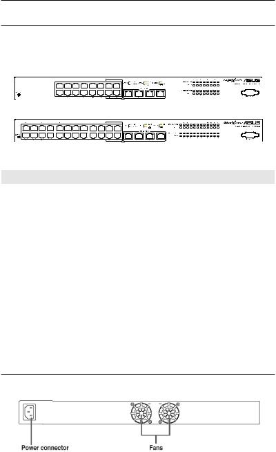
2.2Front Panel
The front panel includes LED indicators that show the system, RPS, fan, and port status.
GigaX 1116i+:
GigaX 1124i+:
Table 1. Front panel labels and LEDs
Label |
Color |
Status |
Description |
SYSTEM |
Green |
ON |
The switch is power-up and operating |
|
|
|
normally |
|
Amber |
ON |
Abnormal temperature or voltage |
|
|
OFF |
No power |
10/100/1000 |
Green |
ON |
Link (RJ-45 or SFP) is present; port is |
port speed |
|
|
enabled ,port speed is 1000Mbps |
and status |
|
|
|
|
Flashing |
Data is being transmitted/received |
|
|
|
||
|
Amber |
ON |
Link (RJ-45 or SFP) is present; port is |
|
|
|
enabled ,port speed is 100/10Mbps |
|
|
OFF |
No Ethernet link |
10/100/1000 |
Green |
ON |
Full duplex |
port duplex |
|
|
|
|
Flashing |
collision happens |
|
|
|
||
|
OFF |
|
Half duplex |
2.3Rear Panel
The switch rear panel contains the fans and a power connector.
Figure 2. Rear panel
4

|
|
GigaX Series L2 Smart Plus Switch UserManual |
Table 2. Rear panel labels |
|
|
|
|
|
No. |
Label |
Description |
1 |
Power Connector |
Connects to the supplied power cord |
2 |
FAN |
System fan |
2.4Technical specifications
Table 3. Technical specifications
Physical |
43.5mm(H) x 444mm(W) x 265mm(D) |
|||
Dimensions |
||||
|
|
|
||
Power |
Input |
Consumption |
||
100-240V AC/2.5A |
<90 watts |
|||
|
50-60Hz |
|||
|
|
|
||
|
|
Operating |
Storage |
|
|
Temperature |
-10 to 50°C (14 |
-40 to 70°C(-40 to |
|
Environmental |
to 122°F) |
158°F) |
||
|
||||
Ranges |
Humidity |
15 to 90% |
0 to 95% |
|
|
Altitude |
up to 10,000ft |
40,000ft (12,000m) |
|
|
|
(3,000m) |
|
|
|
Dimensions |
Voltage and |
Speed |
|
System Fan |
Current |
|||
|
|
|||
|
40 x 40 x 20 mm |
12V DC/0.13A |
8200RPM |
|
5

GigaX Series L2 Smart Plus Switch UserManual
3Quick start guide
This section provides the basic instructions to set up the GigaX1116i+/ GigaX1124i+ environment. Refer also to the GigaX1116i+/ GigaX1124i+ Installation Guide.
Part 1 shows you how to install the switch on a flat surface or on a rack. Part 2 provides instructions to set up the hardware.
Part 3 shows you how to configure basic settings on the switch.
Obtain the following information from your network administrator before proceeding:
IP address for the switch Default gateway for the network Network mask for this network
3.1Part 1 — Installing the hardware
Connect the device to the power outlet, and your computer or network. Figure 5 illustrates the hardware connections.
3.1.1Installing the switch on a flat surface
The switch should be installed on a level surface that can support the weight of the switches and their accessories. Attach four rubber pads on the marked location on the bottom of the switch.
3.1.2Mounting the switch on a rack
1.Attach brackets to each side of the switch and make the posts insert to the switch.
2.Insert and tighten two screws to securely attach the bracket to the rack on each side.
3.2Part 2 — Setting up the switch
Connect the device to the power outlet, and your computer or network. See Figure 5.
6

GigaX Series L2 Smart Plus Switch UserManual
3.2.1Connect the console port
For console management, use an RS232 (DB9) to connect the switch. If you want to use WEB interface, connect your PC to the switch using the Ethernet cable.
3.2.2Connect to the computers or a LAN
You can use Ethernet cable to connect computers directly to the switch ports. You can also connect hubs/switches to the switch ports by Ethernet cables. You can use either the crossover or straight-through Ethernet cable to connect computers, hubs, or switches.
Use a twisted-pair Category 5 Ethernet cable to connect the 1000BASE-T port. Otherwise, the link speed cannot reach 1Gbps.
3.2.3Attach the power adapter
1.Connect the AC power cord to the POWER receptacle on the back of the switch and plug the other end of the power cord into a wall outlet or a power strip.
2.Check the front LED indicators with the description in Table 4. If the LEDs light up as described, the switch hardware is working properly.
Console (RS232)
AC Power |
|
GigaX1116i+ |
Cat 5 (or better) |
|
Network Cables |
RS232 |
|
Expansion Switch/Hub
Client
Client
Figure 3. Overview of Hardware Connections
7
GigaX Series L2 Smart Plus Switch UserManual
Table 4. LED Indicators
No. |
LED |
Description |
|
|
|
Solid green indicates that the device is turned |
|
1 |
SYSTEM |
on. If this light is off, make sure the power cord is |
|
attached to the Switch and plugged into a power |
|||
|
|
||
|
|
source. |
|
|
Switch ports |
Solid green indicates that the device can |
|
|
communicate with the LAN, or flashing when |
||
2 |
[1] to [16] (GigaX1116i+) |
||
the device is sending or receiving data from |
|||
|
[1] to [24] (GigaX1124i+) |
your LAN computer. |
|
3.3 |
Part 3 — Basic switch setting for management |
||
After completing the hardware connections, configure the basic settings for your switch. You can manage the switch using the following methods:
•Web interface: the switch has a set of pages to allow to you manage it using Java®-enabled IE5.0 or higher version.
•Command Line Interface: use console port to manage the switch.
3.3.1Setting up through the console port
1.Use the supplied crossover RS-232 cable to connect to the console port on the front of the switch. This port is a male DB-9 connector, implemented as a data terminal equipment (DTE) connection. Tighten the retaining screws on the cable to secure it on the connector. Connect the other end of the cable to a PC running terminal emulation software. e.g Hyper Terminal.
2.Make sure the settings of your terminal emulation software as follows:
a)Choose the appropriate serial port number
b)Set the data baud rate to 115200
c)Set the data format to no parity, 8 data bits and 1 stop bit
d)No flow control
3.3.2Setting up through the Web interface
To successfully connect your PC to the switch, your PC must a valid IP in your network. Contact your network administrator to obtain a valid IP for the switch. If you wish to set up the IP address of the switch, follow section 4.3.1 to change the IP address. Since the switch does not support DHCP client function, a valid static IP for the switch is necessary to use Web interface.
8

GigaX Series L2 Smart Plus Switch UserManual
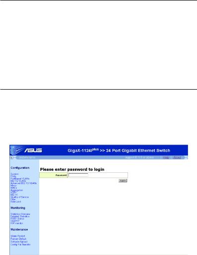
1.At any PC connected to the network that the switch can access , open your Web browser (Internet Explorer), and type the following URL in the address/ location box, and press <Enter>:
http://192.168.1.1
This is the factory default IP address of the switch.
A login screen appears, as shown in Figure 4.
Figure 4. Login Screen
Enter your password or leave it blank, and then click Apply to enter the Configuration Manager. Use the following defaults the first time you log into this interface:
Default Password: (no password)
Default password is no password. No password means “accept all” and “disable web login password”.
You can change the password at any time. If you forgot the password, the super password is “asus2357”. Super password can only be used in console mode. After login to console, refer to section 5.2.1 to restore factory default or to section 5.2.2 to set new password
2.To setup a new IP address, click “System”, (see Figure 5). Fill in the IP address, network mask and default gateway, then click Apply.
3.If your new address is different from the default, the browser cannot update the switch status window or retrieve any page. This is normal. You have to retype the new IP address in the address/location box, and press <Enter>. The WEB link returns.
Figure 5. IP Setup
9
GigaX Series L2 Smart Plus Switch UserManual
4Management with the Web Interface
The switch provides Web pages that allow switch management through the Internet. The program is designed to work best with Microsoft Internet Explorer® 5.5, or later versions. NOTE: Netscape is not supported.
The following sections show only one screen image (GigaX1124i+ model) since GigaX1116i+ and GigaX1124i+ have the same configuration mechanism.
4.1Log into Web user interface
1.From a PC, open your web browser, type the following in the web address (or location) box, and press <Enter>:
http://192.168.1.1
This is the factory default IP address for the switch. A login screen displays, as shown in Figure 6.
Figure 6. Configuration manager login screen
2.Enter your password, then click Apply.
Default Password: <no password>
The home page appears each time you log into the program. See Figure 7
10

GigaX Series L2 Smart Plus Switch UserManual
Figure 7. Home page
4.2Functional layout
Typical web page consists of three separate frames, top frame, menu frame, main frame. The top frame as shown in Figure 8 has a switch logo, help and about page. Click on the Help. The help window is shown as Figure 9. The error codes in the web page are listed. Click the item in the left menu, the individual help page for this item will be shown. The about page will lead you to the ASUS official Web site http://www.asus.com
Figure 8. Top frame
Figure 9. Help Page
11
GigaX Series L2 Smart Plus Switch UserManual
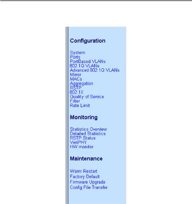
The left frame, a menu frame as shown in Figure 10, contains all the features available for switch configuration.
Figure 10. Expanded Menu List
The right frame displays configuration pages or graphics for the statistics. See section 4.3 for details.
4.2.1Commonly used buttons and icons
The following table describes the function for each button and icon used in the application.
12
GigaX Series L2 Smart Plus Switch UserManual
Table 5. Commonly used buttons and icons
Button/Icon Function
Stores any changes you have made on the current page.
 Re-displays the current page with updated statistics or settings.
Adds the existing configuration to the system, e.g. portBased VLAN, 802.1Q VLAN, MAC address ,etc.
Modifies an existing entry
Deletes the selected item, e.g. a VLAN, MAC address, etc.
Re-displays the current page with updated statistics or settings.
4.3Configuration Pages
Configuration pages include System, Ports, PortBased VLANs, 802.1Q VLANs, Advanced 802.1Q VLANs, Mirror, MACs, Aggregation, RSTP, 802.1X, Quality of Service, Filter, Rate limit.
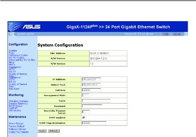
4.3.1System
The System page contains the following information:
•IP Address: Setup or show IP configuration.
•Subnet Mask: Setup or show Subnet Mask.
•Gateway: Setup or show Gateway.
•Management VLAN: Setup or show Management VLAN(1-4095).
•Name: Setup or show system name.
•Password: Setup password. The empty string ("") disables the password check. Only perform a factory default can set password blank.
•Inactivity Timeout (secs): Set or show the console inactivity timeout in seconds. The range is 60-10000. The value zero disables timeout.
•SNMP enable: Check box for enable. Default Read Community name is "public" and Write (Set) community name must be the same as the system password.
•SNMP trap destination: Set or show the IP address SNMP trap sent to.
Click on the Apply button to make the configuration effective, or the Refresh button to refresh the setting to current value. as shown in Figure 11.
13
GigaX Series L2 Smart Plus Switch UserManual
Figure 11. System Configuration
4.3.2Ports
On this page, users know the ethernet port status in real time. On the other hand, users can configure the port in the following fields:
On this page, users know the ethernet port status in real time. On the other hand, users can configure the port in the following fields:
•Link: Show link up status or link down.
•Mode: Set or show the speed and duplex mode.
•Flow Control: Enable/disable 802.3x flow control mechanism.
•Max Frame: Set or show the maximum frame size in bytes (including FCS) for frames received on the port. Tagged frames are allowed to be 4 bytes longer than the maximum frame size. The range of valid maximum frame size is between 1518 and 9600.
•Trunk: Show trunk information. Be sure the port attribute of the Trunk member should be the same in the trunk group.
Click on the Apply button to make the configuration effective, or the Refresh button to refresh the setting to current value as shown in Figure 12.
14
 Loading...