

Page 1
®
Terminator A7VT
Page 2
1
2
©2004
Terminator A7VT
V1 T1651
2004 7
2
Page 3
ASUSTeK COMPUTER INC.( )
150
886-2-2894-3447
0800-093-456 24
886-2-2890-7698
tw.asus.com
ASUS COMPUTER INTERNATIONAL ( )
44370 Nobel Drive, Fremont, CA 94538, USA
+1-502-995-0883
+1-502-933-8713
tmdl@asus.com
+1-502-995-0883
+1-510-608-4555
tsd@asus.com
usa.asus.com
ASUS COMPUTER GmbH ( )
Features
Harkort str. 25, D-40880 Ratingen, Germany
+49-2102-95990
+49-2102-9599011
http://www.asuscom.de
http://www.asuscom.de/sales
+49-2102-95990 ... /
+49-2102-959910 ..
+49-2102-959911
www.asuscom.de/support
Terminator A7VT
3
Page 4
........................................................................................
........................................................................................
..........................................................................................................
........................................................................................
....................................................................................................
............................................................................................
2
3
4
7
7
8
....................................................
1.1
1.2
1.3
1.4
................................................................................
................................................................................
..................................................
2.1
2.2
2.3
2.4 CPU
2.4.1 CPU
2.4.2 CPU
2.5
2.5.1
2.5.2
2.5.3
2.6
2.7
2.8
2.8.1
2.8.2
2.9
2.9.1
2.9.2 UAEX
....................................................................................
........................................................................................
............................................................................
................................................................................................
....................................................................................
.............................................................................................
.....................................................................................
.....................................................................................
....................................................................................
....................................................................................
............................................................................................
.............................................................................................
.............................................................................................
.........................................................................................
9
11
........................................................................
........................................................................
12
13
14
15
17
19
19
....................................................................
...............................................................................
....................................................................
..........................................................
21
21
23
25
25
26
27
28
30
32
32
33
34
34
35
4
Page 5
2.10
2.11
2.12
..........................................................................................
..........................................................................
..............................................................................
36
38
39
..................................................
3.1
3.2
3.3
3.3.1
3.3.2
3.3.3
3.3.4
3.4
................................................................................
........................................................................................
..............................................................
..........................................................................................
......................................................................................
..................................................................................................
............................................................................
...............................................
4.1
4.2
4.3
4.4
BIOS
5.1 BIOS
5.1.1
5.1.2
5.1.3 CrashFree BIOS BIOS
5.1.4
5.2 BIOS
5.2.1 BIOS
5.2.2
5.3 Main Menu
5.3.1 System Time [XX:XX:XX]
5.3.2 System Date [XX/XX/XXXX]
5.3.3 Legacy Diskette A [1.44M, 3.5 in.]
...................................................................................
................................................................................
....................................................................
........................................................................................
................................................
......................................................................
......................................................................................
AwardBIOS Flash BIOS
..................................................................................
......................................................................................
........................................................................................
.....................................................................................
.................................................................
...................................................................
..............................................................
43
43
43
....................................................
44
44
45
46
46
47
53
55
55
56
58
73
67
67
................................................
.................................................
.......................................................
68
70
70
72
73
73
75
75
75
75
Terminator A7VT
5
Page 6
5.3.4 Installed Memory [XXX MB]
5.3.5 IDE Primary & Secondary Master/Slave
5.4 Advanced Menu
5.4.1 CPU Configuration
5.4.2
5.4.3 Chip Configuration
5.4.4 PCI
5.4.5 Onboard Device Configuration
5.4.6 USB USB Configuration
Memory Configuration
PCI PnP
5.5 Power menu
5.5.1 APM Configuration
5.5.2 Hardware Monitor
5.6 Boot Menu
5.6.1 Boot Device Priority
5.6.2
5.6.3
5.6.4
5.6.5
5.6.6
Removable drives
Hard Disk Drives
CD-ROM drives
Boot Settings Configuration
Security
5.7 Exit Menu
................................................................
.....................................................
.......................................................
.......................................................
.....................................................
...................................................................
.................................................
............................................................
................................................
.......................................................
..............................................................
...............................................
........................................................
.................................................................
..................................................................
............................................
...........................................................................
...............................................................
...............................
......................................
75
76
77
77
78
79
80
82
84
85
86
88
90
90
91
91
92
92
94
96
6
Page 7
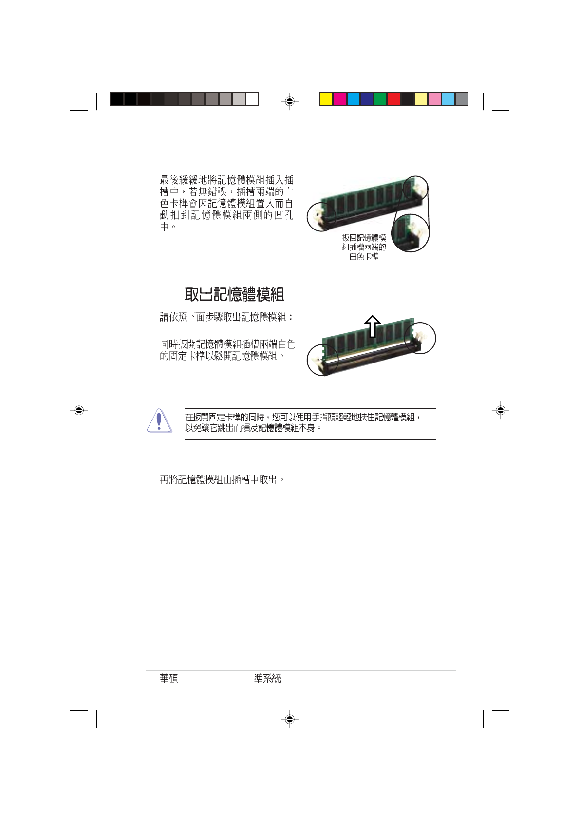
1.
2.
step-by-step
7.
5.
Jumper
6. BIOS
BIOS BIOS
Terminator A7VT
7
Page 8
IC
8
Page 9
Terminator
Page 10
1.1
1.2
1.3
1.4
................................................................................
........................................................................
........................................................................
................................................................................
11
12
13
14
Page 11
1.1
1)
2)
3)
4) 1.44MB
5)
6)
CD-ROM CD-RW DVD-ROM DVD-RW
1.
2.
Terminator A7VT
11
Page 12
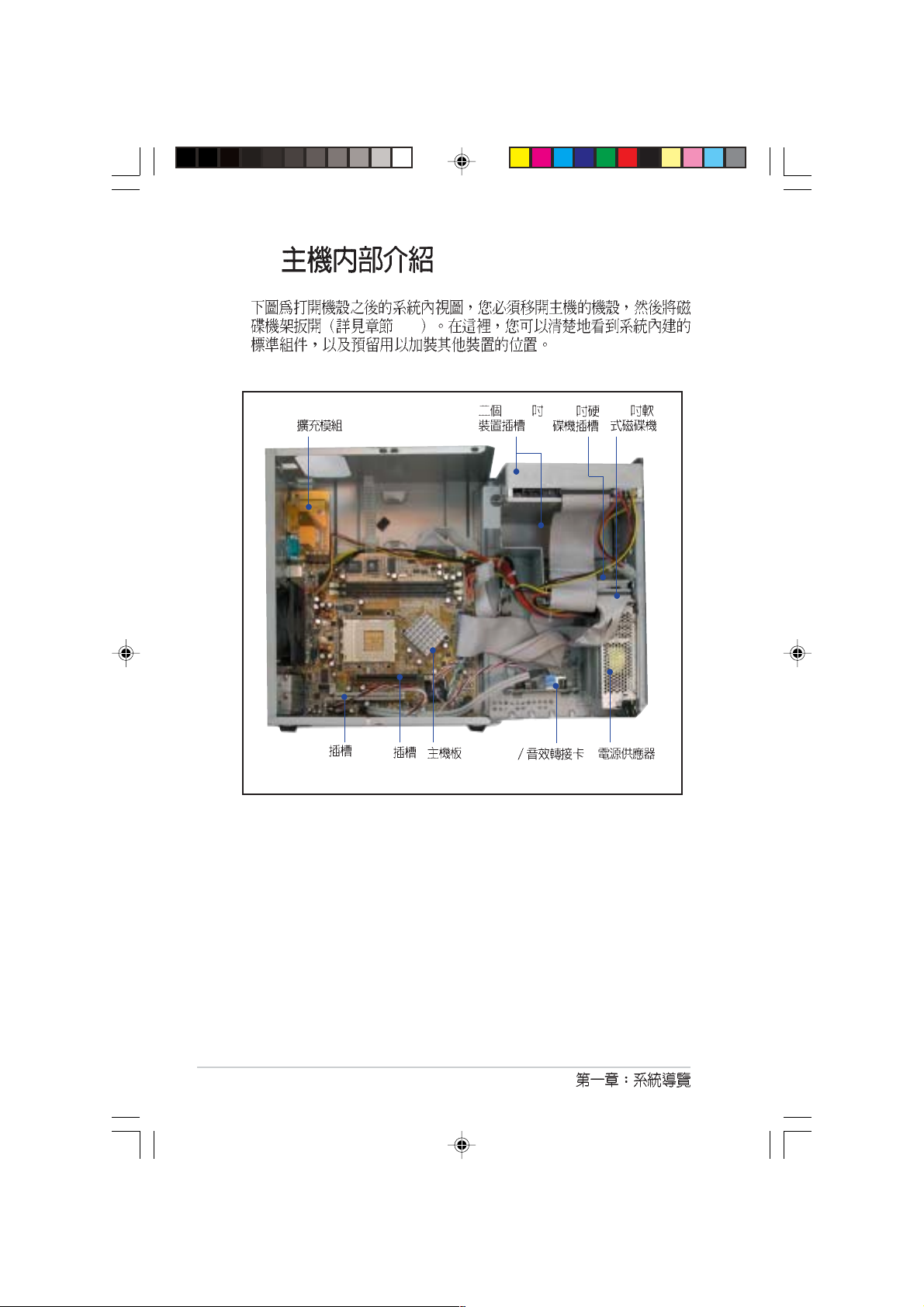
1.2
Terminator A7VT A7VT
5.25
12
USB
I/O USB (2&3 )
Page 13
1.3
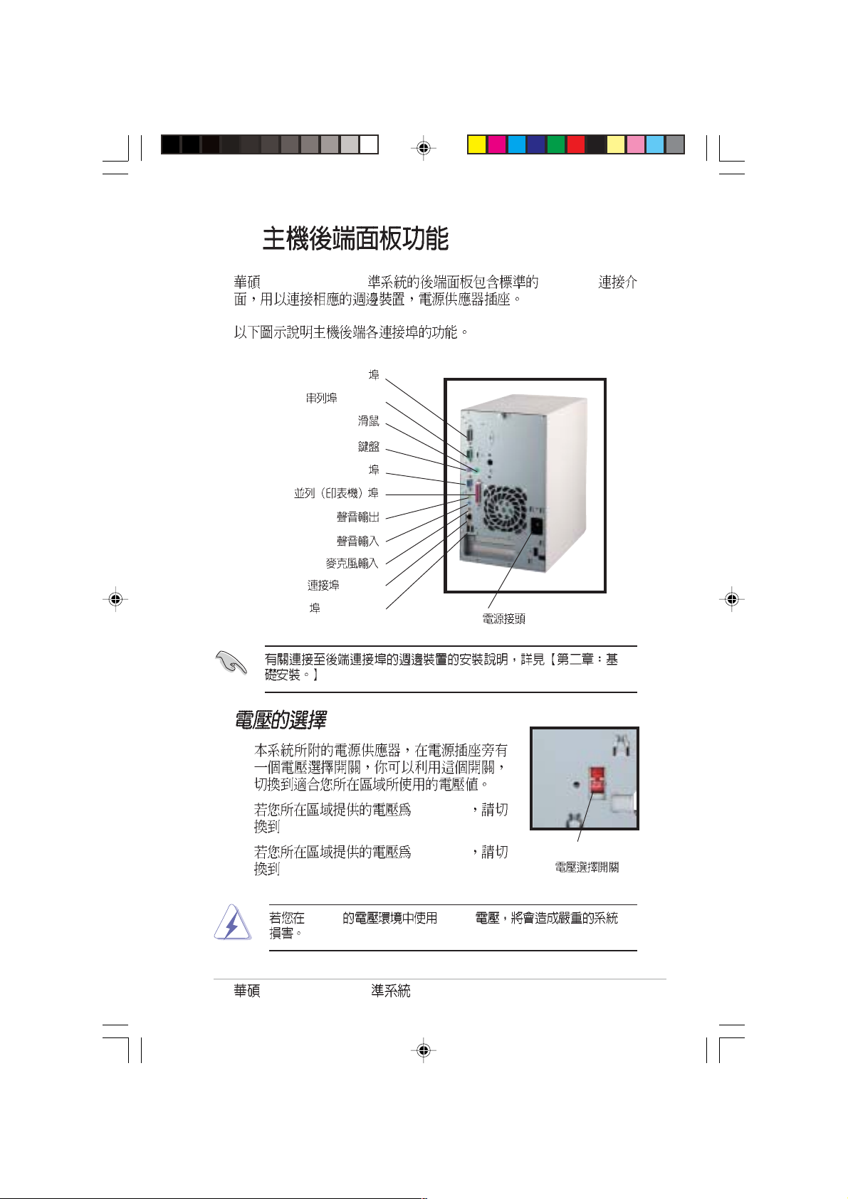
Terminator A7VT PC99 I/O
Game/MIDI
(COM1)
PS/2
PS/2
VGA
LAN (RJ-45)
USB (Ports 1&2)
115V
230V
230V 115V
Terminator A7VT
100-127V
200-240V
115V/230V
13
Page 14
1.4
2.1
Game/MIDI/Com1
PCI
AGP
5.25
USB
3.5
3.5
14
Page 15
step-by-step
Terminator
Page 16
2.1
2.2
2.3
2.4 CPU
2.4.1 CPU
2.4.2 CPU
2.5
2.5.1
2.5.2
2.5.3
2.5.4
2.6
2.7
2.8
2.8.1
2.8.2
2.9
2.9.1
2.9.2 UAEX
2.10
2.11
2.12
....................................................................................
........................................................................................
............................................................................
...................................................................................
....................................................................................
................................................................................
....................................................................................
....................................................................................
............................................................................................
................................................................................
................................................................................
............................................................................
..........................................................................................
..............................................................................
17
19
19
....................................................................
..................................................................
....................................................................
........................................................................
........................................................................
....................................................................
.............................................
..........................................................................
21
21
23
25
25
25
26
27
28
30
32
32
33
34
34
35
36
38
39
16
Page 17
2.1
1.
2.
3.
4.
5.
/
(1) (2) (3)
A7VT
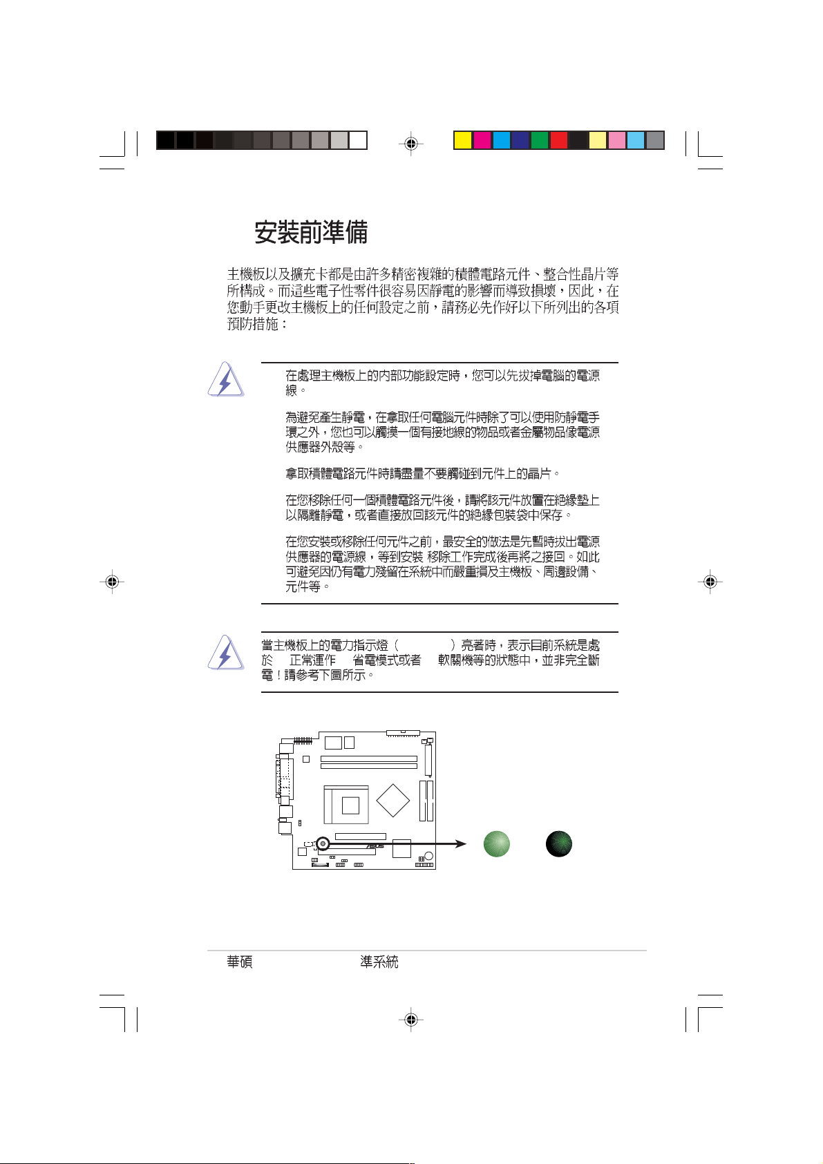
®
A7VT Onboard LED
Terminator A7VT
SB_PWR
SB_PWR
ON OFF
Standby
Power
Powered
Off
17
Page 18
2.2
1.
2.
18
3.
Page 19
2.3
1.
2.
Terminator A7VT
19
Page 20
3.
4.
20
5.
Page 21

2.4 CPU
A7VT 462
ZIF AMD Athlon/Duron
2.4.1 CPU
CPU
1. CPU
A7VT
®
A7VT Socket 462
CPU NOTCH
TO INNER
CORNER
LEVER
CPU NOTCHLOCK
AMD™ CPU
2. Socket A
Terminator A7VT
90
21
Page 22
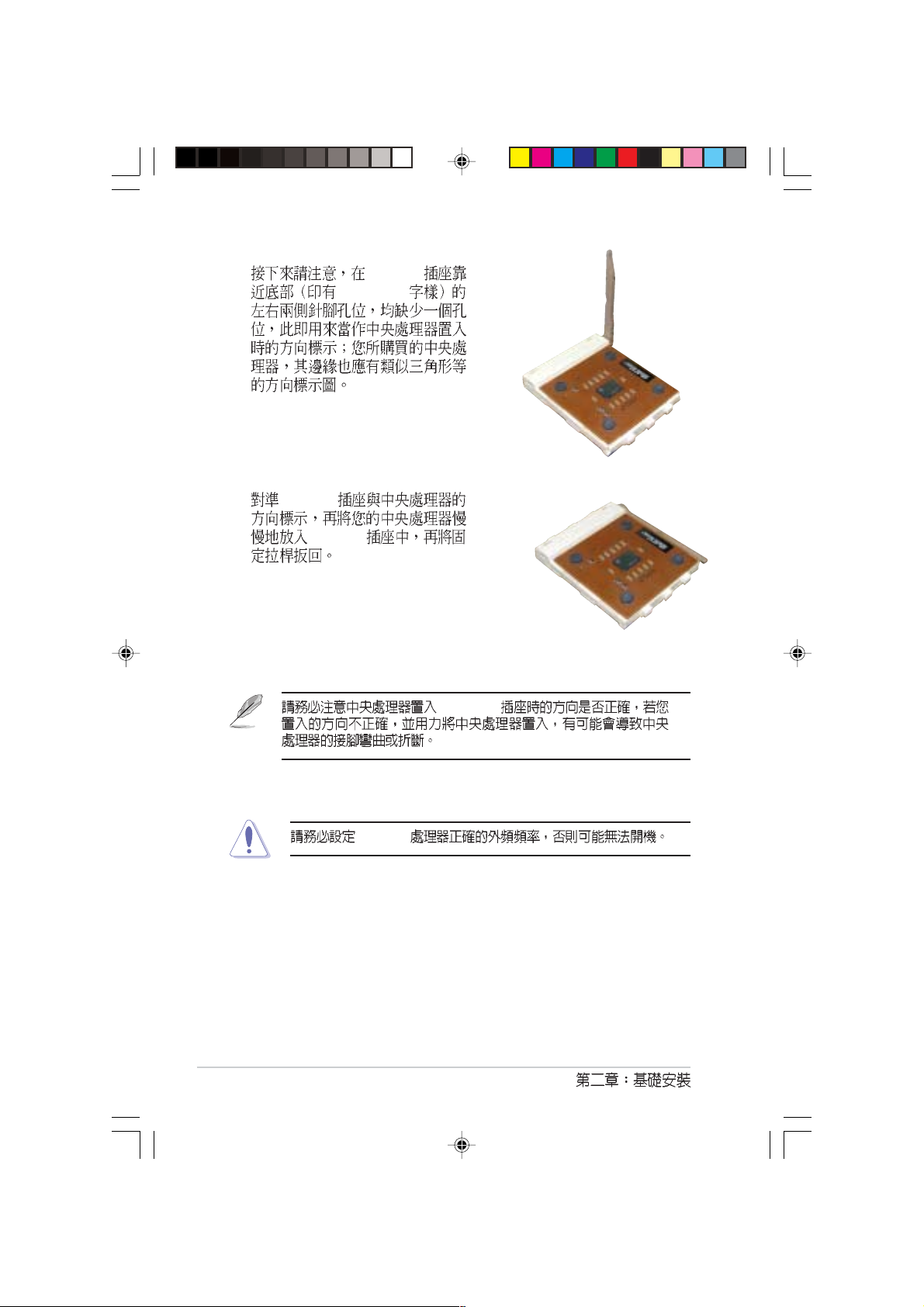
3. Socket A
Socket 462
4. Socket A
Socket A
Socket A
22
Socket A
Page 23
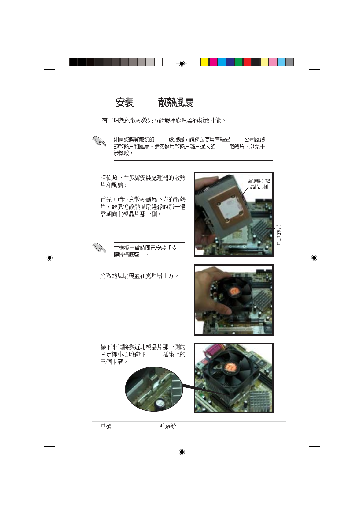
2.4.2 CPU
AMD AMD
1.
2.
CPU
3.
CPU
Terminator A7VT
23
Page 24
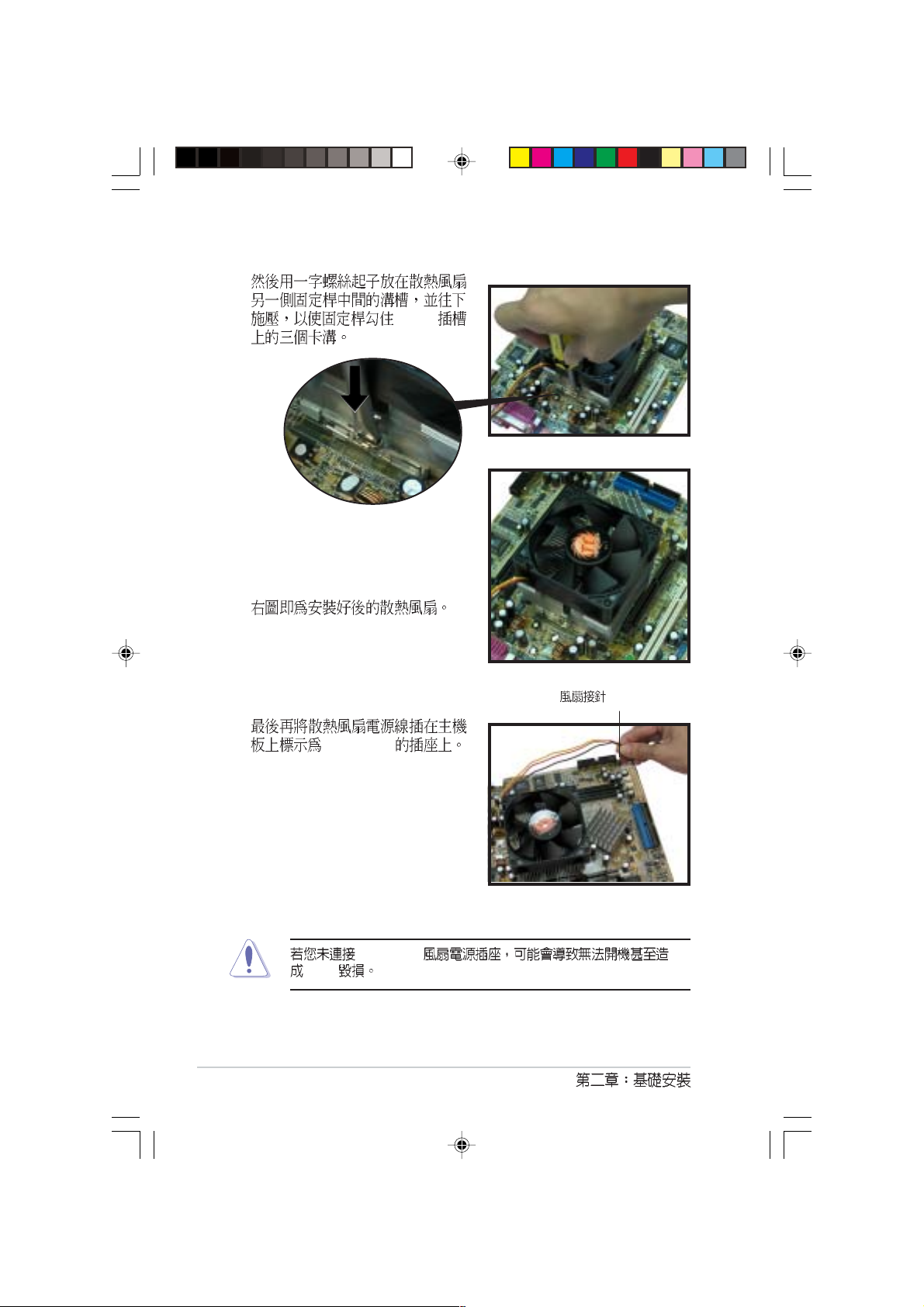
4.
5.
6.
CPU
CPU (CPU_FAN)
CPU_FAN
24
CPU_FAN
CPU
Page 25
2.5
184-pin DDR DIMM Double Data Rate
unbuffered non-ECC PC2700/
2100/1600 DDR DIMM 2 GB
2.5.1
64, 128, 256, 512MB 1GB DDR DIMM
CPU
CPU FSB DDR DDR
100MHz PC2700/PC2100/PC1600 266MHz/266MHz/200MHz
133MHz PC2700/PC2100/PC1600 333MHz/266MHz/200MHz
166MHz PC2700/PC2100/PC1600 333MHz/266MHz/200MHz
333MHz PC3200 DDR
DIMM 333MHz
CPU FSB 100MHz 266Mhz
Terminator A7VT
25
Page 26

2.5.2
1. DDR DIMM
A7VT
®
A7VT 184-Pin DDR DIMM Sockets
2.
3.
80 Pins104 Pins
DIMM2
DIMM1
26
DDR DIMM
Page 27
4.
2.5.3
1.
2.
Terminator A7VT
27
Page 28
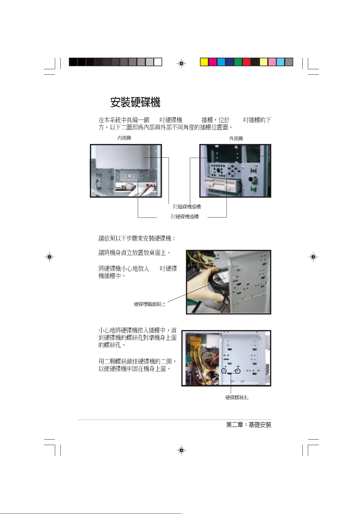
2.6
3.5 (HDD) 5.25
1.
2. 3.5
5.25
3.5
28
3.
4.
Page 29
5.
P3
6. IDE
IDE IDE
7. IDE
PRI_IDE
IDE
IDE
(P3)
IDE
(PRI_IDE)
Terminator A7VT
29
Page 30
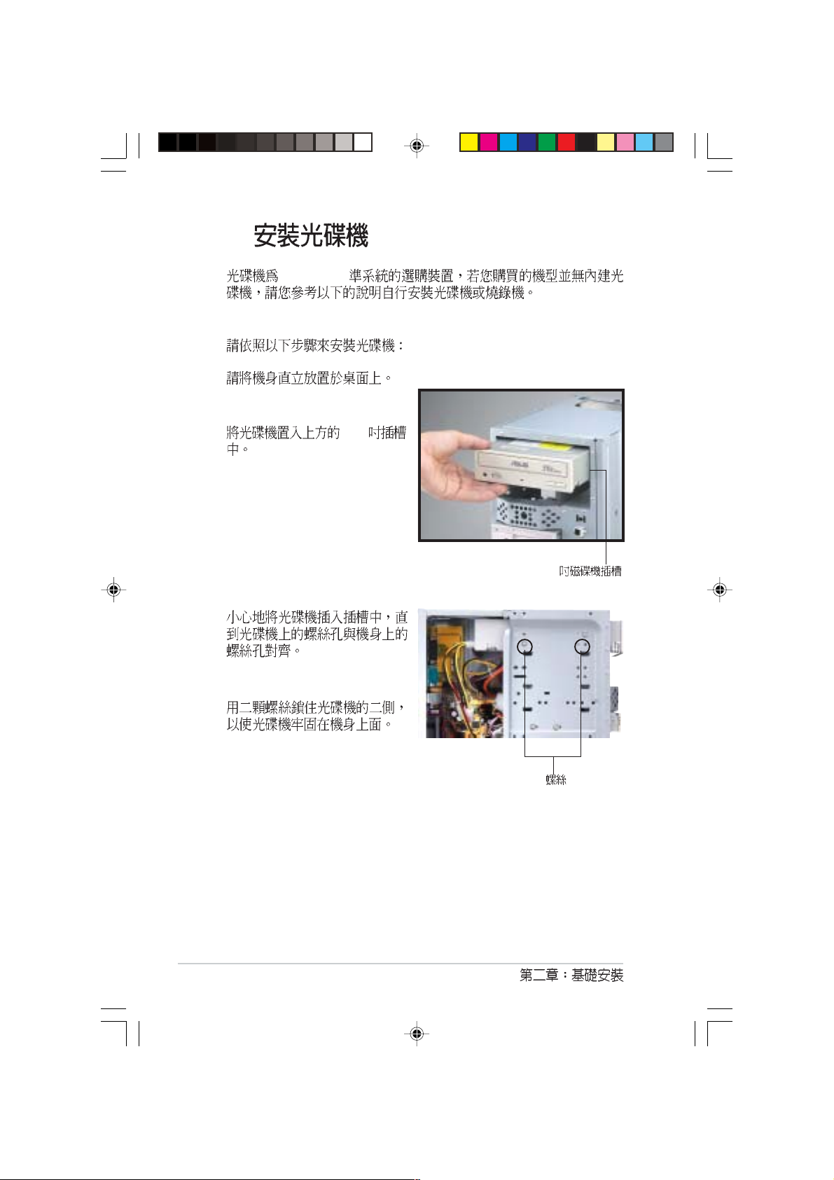
2.7
Terminator
1.
2. 5.25
3.
5.25
30
4.
Page 31

5.
P1
6. IDE
7.
4-pin
8. IDE
SEC_IDE )
IDE
CD-ROM
IDE
(P1)
IDE (
9.
CD 4-pin
CD-ROM (CD)
Terminator A7VT
IDE (SEC_IDE)
31
Page 32

2.8
32-bit PCI AGP
PCI
AGP
2.8.1
PCI AGP
1.
2. PCI AGP
3. PCI AGP PCI AGP
4.
5.
PCI AGP PCI
AGP
AGP
3.3V AGP 1.5V
AGP
PCI
PCI
32
Page 33

2.8.2
1. BIOS
BIOS
2.
IRQ
01
12
2 N/A
3* 11 USB
4* 12 COM 1
5* 13 USB
614
7* 15 LPT 1
83 CMOS
9* 4 ACPI
10* 5
11* 6
12* 7 PS/2
13 8
14* 9 IDE
15* 10 IDE
*
PCI
AGP
USB 1.1 UHC1 1
USB 1.1 UHC1 2
USB 1.1 UHC1 3
USB 2.0 EHC1
Terminator A7VT
ABCDEFGH
33
Page 34

2.9
2.9.1
PANEL
Power Switch Power LED
Message LED
34
A7VT
®
A7VT System panel connector
PLED
+5VSB
+5 V
HDLED
*
Requires an ATX power supply.
PLED
NC
HDLED
SMI
SPEAKER
PWR
Ground
ExtSMI#
PWRBTN*
Ground
+5V
Ground
RESET
Speaker
Ground
Reset
Ground
Page 35

2.9.2 UAEX
UAEX
MIC
MIC2
LO2
LOUT
®
UAEX
T: Port0
B: Port1
USB2P
USB
USB_34
MIC_LOUT
USB_56
USB_34
MIC_LOUT
Line Out
Terminator A7VT
35
Page 36

2.10
1.
2.
3.
36
4.
2
Page 37

5.
6.
7.
Terminator A7VT
37
Page 38

2.11
PS/2
Game/
MIDI
VGA
RJ-45
PS/2
USB
38
Page 39

2.12
1 90V 115V 135V
2 180V 230V 265V
47 Hz to 63 Hz
AC 4A max at 115Vac
2A max. at 230Vac, maximum load
90A max. at 115Vac,
full load cold start at 25
70% min. at nominal input,
maximum load
Load Range Regulation Ripple
+5V 0.5A 4.0A -5% +5% 50mV
+12V 0.45A 9.5A -5% +5% 120mV
-12V 0A 0.2A -10% +10% 120mV
+5Vsb 0.05A 1.5A -5% +5% 50mV
+3V3 1A 8.0A -5% +5% 50mV
Over-Voltage Protection (OVP)
+5V 6.5V
+12V 15.6V
+3.3V 4.3V
+5V +12V -12V +3.3V
+5Vsb
Terminator A7VT
p-p
p-p
p-p
p-p
p-p
39
Page 40

40
Page 41

Page 42

3.1
3.2
3.3
3.4
3.3.1
3.3.2
3.3.3
3.3.4
................................................................................
........................................................................................
....................................................
.................................................
.............................................................................
.........................................................................
.....................................................................................
............................................................................
43
43
44
44
45
46
46
47
Page 43

3.1
3.2
Windows 98SE/ME/2000/XP
Terminator A7VT
43
Page 44

3.3
3.3.1
http://www.asus.com.tw
44
Page 45

3.3.2
ASUS PC Probe
ASUS
Update
BIOS
ISP
Microsoft DirectX
Microsoft DirectX 9.0
PC-cillin 2002
PC-cillin 2002 V7.61 PC-cillin
ADOBE Acrobat Reader V5.0
Adobe Acrobat Reader 5.0 PDF Portable
Document Format
Terminator A7VT
45
Page 46

3.3.3
3.3.4
46
Page 47

3.4
3.4.1
CPU
Show up in next execution
Terminator A7VT
\
- ASUS Utility\Probe Vx.xx Vx.xx
Tray
47
Page 48

3.4.2
CPU
CPU
CPU
CPU
48
CPU
Page 49

CPU
CPU
CPU CPU
CPU
CPU
FAT
Terminator A7VT
49
Page 50

50
DMI
CPU
CPU
Page 51

3.4.3
CPU !!!
Terminator A7VT
51
Page 52

52
Page 53

A7VT
BIOS
<Del>
( )
Jumper
BIOS
Page 54

4.1
4.2
4.3
4.4
...................................................................................
................................................................................
....................................................................
........................................................................................
55
55
56
58
Page 55

4.1
4.2
PS/2
T:Mouse
B:Keyboard
VGA
Line
Out
Line
In
Mic
In
A7VT
IOC_MB
ATX12V
PARALLEL PORT
23cm (9.06in)
Super
I/O
Flash
BIOS
DDR DIMM2 (64/72-bit, 184-pin module)
DDR DIMM1 (64/72-bit, 184-pin module)
FLOPPY
KM266 PRO
CHA_FAN
CPU_FAN
ATX Power Connector
VIA
RJ-45
LANLED
USB
T:Port2
B:Port1
USBPWR12
CD
AD1888
MIC_LOU
BATTERY
Terminator A7VT
AUX
Socket 478
Accelerated Graphics Port (AGP)
SB_PWR
PCI1
USBPWR34
USBPWR56
USB34
USB56
A7VT
®
VIA
VT8235 CE
CLRTC
PANEL
FSB
PRI_IDE
BUZZER
22.4cm (8.82in)
SEC_IDE
55
Page 56

4.3
1. USB 3-pin USB_PWR12, USB_PWR34,
USB_PWR56
+5V USB S1
(CPU DRAM
) +5VSB USB S3 S4
S5 CPU DRAM
USBPWR12 USB USBPWR34
USBPWR56 USB
USB
1. USB 0.5A +5VSB
1.5A USB
1.5A/+5VSB
2.
+5VSB
3. S3 S4 S5
+5VSB
56
A7VT
®
A7VT USB device wake-up
USBPWR12
USBPWR34
USBPWR56
22
1
12
+5V
12
+5V
3
+5VSB+5V
(Default)
23
+5VSB
(Default)
23
+5VSB
(Default)
Page 57

2. BIOS Clear RTC RAM CLR_RTC
CMOS
CMOS
1
2
3 CLRTC [2-3] CMOS
4 CLRTC [1-2]
5
6 <Del> BIOS
BIOS
A7VT
®
12
Clear CMOS
A7VT Clear RTC RAM
3. CPU FSB
FSB CPU FSB
CPU FSB 100MHz 2-3 CPU FSB
CPU FSB 133 166MHz
1-2
A7VT
®
A7VT External Frequency Selection
Terminator A7VT
12
133/166
(Default)
CLRTC
FSB
23
Normal
(Default)
100
23
57
Page 58

4.4
1. IDE 40-1 pin PRI_IDE, SEC_IDE
IDE IDE IDE
( CD-ROM/DVD-ROM) IDE
Master Slave
PRI_IDE IDE IDE
PIN1 UltraDMA/133/100/66
UltraDMA/133/100/66 CD-ROM/DVD-ROM
2.7
20
NOTE: Orient the red markings
(usually zigzag) on the IDE
ribbon cable to PIN 1.
A7VT
®
SEC_IDE
A7VT IDE Connectors
PRI_IDE
PIN 1
2. (34-1 pin FLOPPY)
A7VT
®
A7VT Floppy Disk Drive Connector
58
FLOPPY
NOTE: Orient the red markings on
the floppy ribbon cable to PIN 1.
Page 59

3. (4-pin AUX, CD)
MPEG
CD-ROM
AUX (White)
Ground
A7VT
Ground
Left Audio Channel
Right Audio Channel
Right Audio Channel
®
CD (Black)
Left Audio Channel
A7VT Internal audio connectors
4. ATX (20-pin ATXPWR, 4-pin ATX +12V)
ATX +12V
20 ATXPWR
Pentium 4 +12V
ATXPWR
+12.0Volts
+5V Standby
Power Good
Ground
+5.0 Volts
Ground
+5.0 Volts
Ground
+3.3 Volts
+3.3 Volts
+5.0 Volts
+5.0 Volts
-5.0 Volts
Ground
Ground
Ground
Power Supply On
Ground
-12.0Volts
+3.3Volts
A7VT
®
A7VT ATX Power Connector
Terminator A7VT
ATX12V
+12V DCCOM
+12V DCCOM
59
Page 60

5. / (3-pin CPU_FAN, CHA_FAN)
+12V 350mA~740mA 8.88
1A~2.22A 26.64
CHA_FANCPU_FAN
GND
+12V
Rotation
A7VT
®
A7VT Fan connectors
CPU
CPU jumpers
jumper
6. (5-1 pin MIC_LOUT)
A7VT
®
Rotation
MIC_LOUT
Head set Left channel
GNDHead set Right channel
1
1
MIC SignalMIC PWR
GND
+12V
60
A7VT Front panel audio connector
Page 61

7. USB 2.0 (10-1 pin USB_34,USB_56)
USB_34 UAEX USB2P
USB2.0
USB Power
USBP4–
USBP4+
GND
A7VT
A7VT USB connector
®
USB34 USB56
NC
210
19
GND
USBP3–
USBP3+
USB Power
8. IO (22-pin IOC_MB)
CGAEX
USB Power
USBP6–
USBP6+
GND
NC
210
19
GND
USBP5–
USBP5+
USB Power
A7VT
®
A7VT CGAEX extension module
Terminator A7VT
COM1
CGAEX
IOC_DC
GAME
®
61
Page 62

9. (20-pin PANEL1)
20-pin
A7VT
®
A7VT System panel connector
3-1 pin PLED
4-pin SPEAKER
4-pin
2-pin HDLED
SMI 2-pin SMI
SMI
PLED
+5VSB
+5 V
HDLED
*
Requires an ATX power supply.
PLED
NC
HDLED
SMI
SPEAKER
PWR
Ground
ExtSMI#
PWRBTN*
Ground
+5V
Ground
RESET
Speaker
Ground
Reset
Ground
62
Turbo BIOS
Power Menu Suspend Mode
ACPI
Page 63

(2-pin PWRBTN)
(2-pin RESET)
Terminator A7VT
63
Page 64

64
Page 65

BIOS
( )
BIOS
<Del>
BIOS
BIOS
BIOS
Page 66

5.1 BIOS
5.1.1
5.1.2 AwardBIOS Flash BIOS
5.1.3 CrashFree BIOS BIOS
5.1.4
5.2 BIOS
5.2.1 BIOS
5.2.2
5.3 Main Menu
5.3.1 System Time [XX:XX:XX]
5.3.2 System Date [XX/XX/XXXX]
5.3.3 Legacy Diskette A [1.44M, 3.5 in.]
5.3.4 Installed Memory [XXX MB]
5.3.5 IDE Primary & Secondary Master/Slave
5.4 Advanced Menu
5.4.1 CPU Configuration
5.4.2 Memory Configuration
5.4.3 Chip Configuration
5.4.4 PCI PCI PnP
5.4.5 Onboard Device Configuration
5.4.6 USB USB Configuration
5.5 Power menu
5.5.1 APM Configuration
5.5.2 Hardware Monitor
5.6 Boot Menu
5.6.1 Boot Device Priority
5.6.2 Removable drives
5.6.3 Hard Disk Drives
5.6.4 CD-ROM drives
5.6.5 Boot Settings Configuration
5.6.6 Security
5.7 Exit Menu
......................................................................................
......................................................................
.........................................................................
...................................
....................................
.....................................................................
...........................................................................
........................................................................
.................................................................
.......................................................
..................................................
...........................................
...................................................
.....................................................
..........................................
..........................................
........................................
......................................................
.........................
....................................
............................................................
...................................
..........................................
..............................................................
...................................
...........................................
....................................................
.....................................................
...............................
...............................................................
...............................................................
..................
67
67
68
70
70
72
73
73
75
75
75
75
75
76
77
77
78
79
80
82
84
85
86
88
90
90
91
91
92
92
94
96
Page 67

5.1 BIOS
BIOS
1. AwardBIOS Flash Utility POST
BIOS
2. ASUS CrashFree BIOS BIOS BIOS
BIOS
3. ASUS Update Windows BIOS
•
•
ASUS Update AFLASH BIOS
BIOS
ASUS Update BIOS
5.1.1
1.
DOS
a. 1.44 MB DOS
format A:/S <Enter>
b.
Windows XP
a. 1.44 MB
b.
c. 3.5
d.
e. MS-DOS
2. BIOS
Terminator A7VT
67
Page 68

5.1.2 AwardBIOS Flash BIOS
Flash Memory Writer
AWDFLASH.EXE BIOS
BIOS
1. http://www.asus.com BIOS
.BIN
BIOS
2. BIOS
3.
4. POST <Alt> + <F2>
Page 69

5. AWDFLASH
6. AWDFLASH
7.
Page 70

5.1.3 CrashFree BIOS BIOS
CrashFree BIOS BIOS
BIOS
1. BIOS BIOS
2. BIOS
BIOS
BIOS
1.
2. BIOS
Bad BIOS checksum. Starting BIOS recovery...
Checking for floppy...
3. BIOS
BIOS
BIOS
70
BIOS A7VT.BIN
Bad BIOS checksum. Starting BIOS recovery...
Checking for floppy...
Floppy found!
Reading file “a7vt.bin”. Completed.
Start flashing...
BIOS
4.
BIOS
Page 71

5.1.4
1.
AsusUpdate Vx.xx.xx
ASUSUpdate Vx.xx.x
2.
Next
3.
Auto Select
BIOS
FTP
Next
4. BIOS
Next
5.
BIOS
BIOS
BIOS
Terminator A7VT
71
Page 72

5.2 BIOS
BIOS Basic Input and Output System
BIOS
BIOS
BIOS
RUN SETUP BIOS
BIOS
EEPROM Electrical Erasable Programmable
Read-Only Memory BIOS EEPROM
BIOS BIOS
BIOS
CMOS RAM
BIOS
72
POST Power-On Self Test
DELETE
DELETE
RESET ALT - CTRL - DEL
BIOS
BIOS
BIOS
BIOS
Page 73

5.2.1 BIOS
BIOS
MAIN
ADVANCED BIOS
POWER
BOOT
EXIT BIOS
5.2.2
BIOS
<F1> or <Alt + H>
<Esc> or<Alt + X>
Exit
or
← ←
←
← ←
↑↑
↑ or
↑↑
- (minus key)
+ (plus key) or spacebar
<Enter>
<Home> or <PgUp>
<End> or <PgDn>
<F5>
<F10>
(keypad arrow)
→ →
→
→ →
↓ ↓
↓ (keypad arrows)
↓ ↓
Terminator A7VT
BIOS
73
Page 74

F1 Alt + H
PgUp PgDn
Home
End Enter
Esc
Enter
ESC
BIOS
BIOS
BIOS
BIOS F5
74
BIOS
5.7 BIOS
1. BIOS
BIOS
2. [ ] BIOS
BIOS
Page 75

5.3 Main Menu
BIOS
System Time 09:40:12
System Date Wed., May 19 2004
Legacy Diskette A [1.44M, 3.5 in.]
IDE Primary Master[Auto]
IDE Primary Slave [Pioneer CD-ROM A]
IDE Secondary Master [None]
IDE Secondary Slave [None]
Installed Memory [256 MB]
5.3.1 System Time [XX:XX:XX]
00 23 00 59 00 59 Tab
Tab + Shift
5.3.2 System Date [XX/XX/XXXX]
1 12 1 31 00 99 Tab
Tab + Shift
Select Menu
Item Specific Help
Change the internal
clock.
5.3.3 Legacy Diskette A [1.44M, 3.5 in.]
[Disabled] [360K
5.25 in.] [1.2M 5.25 in.] [720K 3.5 in.] [1.44M 3.5 in,] [2.88M 3.5 in.]
5.3.4 Installed Memory [XXX MB]
Terminator A7VT
75
Page 76

5.3.5 IDE
BIOS IDE
ATA IDE ATA
IDE Primary Master
Primary IDE Master [Auto]
Access Mode [Auto]
Capacity 0 MB
Cylinder 0
Head 0
Sector 0
PIO Mode [Auto]
UDMA Mode [Auto]
Transfer Mode None
Primary IDE Master [Auto]
[Auto] IDE
Primary & Secondary Master/Slave
[Enter]
Select Menu
Item Specific Help
Press [Enter] to
select.
Access Mode [Auto]
[Large] [Auto]
PIO Mode [Auto]
PIO Programmed Input/Output
IDE Mode 0 Mode 4
[Auto][Mode 0] [Mode 1] [Mode 2] [Mode 3] [Mode 4]
UDMA Mode [Auto]
Ultra DMA IDE
[Disabled] Ultra DMA
76
BIOS IDE
sector addressing [CHS] [LBA]
BIOS
Page 77

5.4 Advanced Menu
CPU Configuration
Memory Configuration
Chipset
PCIPnP
Onboard Device Configuration
USB Configuration
Select Menu
Item Specific Help
Press [Enter] to Set.
5.4.1 CPU Configuration
CPU Configuration
CPU Type AMD Athlon
(tm)
CPU Speed 1000 MHz
Cache RAM 256 K
Current FSB Frequency 100 MHz
Select Menu
Item Specific Help
Terminator A7VT
77
Page 78

5.4.2 Memory Configuration
Memory Configuration
Current DRAM Frequency 133 MHz
DRAM Clock [By SPD]
DRAM Timing [Auto by SPD]
x DRAM CAS Latency 2.5
x Bank Interleave Disabled
x Precharge to Active (Trp) 5T
x Active to Precharge (Tras) 7T
x Active to CMD (Trcd) 5T
DRAM Burst Length [4]
DRAM Command Rate [2T Command]
Write Recovery Time [3T]
tWTR [2T]
DRAM Clock [By SPD]
DRAM [By SPD] [133MHz] [166MHz]
DRAM Timing [Auto by SPD]
SPD Serial Presence Detect
DRAM clock [Auto by SPD] DRAM clock
[Manual] DRAM Timing [Safe] DRAM Timing
[Auto by SPD] [Manual] [Safe]
DRAM Burst Length [4]
DRAM Burst Length [4] [8]
Select Menu
Item Specific Help
Set DRAM Frequency.
DRAM Commend Rate [2T Command]
DRAM Commend Rate [1T Command] [2T Command]
Write Recovery Time [3T]
DRAM Write Recovery Time [2T] [3T]
tWTR [2T]
tWTR [1T] [2T]
78
BIOS
Page 79

5.4.3 Chip Configuration
Chipset
AGP Display Switch [Auto]
Init Display First [PCI slot]
AGP Bridge Configuration
AGP Display Switch [Auto]
[Auto] AGP [Onchip AGP]
AGP
[Åuto] [Onchip AGP]
Init Display First [Auto]
PCI AGP [PCI
slot] [AGP]
AGP Bridge Configuration
Select Menu
Item Specific Help
Graphics Aperture Size [64MB]
AGP
[4MB] [8MB] [16MB] [32MB] [64MB] [128MB] [256MB]
[512MB][1G]
AGP Mode [4X]
1066MB AGP 4X
[4X] AGP 1X 2X [1X]
AGP 4X AGP 266MB
[1X] [2X] [4X]
Terminator A7VT
79
Page 80

AGP Fast Write [Disabled]
AGP Fast Write AGP Fast Write
AGP PCI
[Disabled][Enabled]
Onboard Video Memory [32MB]
3D 16MB
[16MB][32MB][64MB]
5.4.4 PCI PCI PnP
PCI/PnP PCI/PnP
IRQ DMA
80
PCIPnP
Plug & Play O/S [No]
Resources Controlled By [Auto]
x IRQ Resources
PCI/VGA Palette Snoop [Disabled]
Assign IRQ for VGA [Enabled]
Select Menu
Item Specific Help
BIOS
Page 81

Plug and Play O/S [No]
[No] BIOS
[No] [Yes]
Resources Controlled By [Auto]
[Auto] BIOS
[Manual] IRQ PCI
[Auto] [Manual]
Resources Controlled By [Auto] IRQ Resources
PCI/VGA Pallete Snoopping [Disabled]
MPEG
[Enabled]
VGA
[Disabled] [Disabled] [Enabled]
Assign IRQ VGA [Enabled]
IRQ VGA [Disabled]
[Enabled]
[Yes]
Terminator A7VT
81
Page 82

5.4.5 Onboard Device Configuration
Onboard Device Configuration
Onboard LAN Boot ROM [Disabled]
AC97 Audio [Auto]
Onboard LAN [Enabled]
Serial Port1 Address [3F8/IRQ4]
Parallel Port Address [378/IRQ7]
Parallel Port Mode [ECP+EPP]
EPP Mode Select [EPP1.7]
ECP Mode Use DMA [3]
Game Port Address [201]
Midi Port Address [Disabled]
x Midi Port IRQ 10
OnBoard LAN Boot ROM [Disabled]
OnBoard LAN [Enabled]
[Disabled] [Enabled]
AC 97 Audio [Auto]
AC97
[Disabled] [Auto]
OnBoard LAN [Enabled]
Select Menu
Item Specific Help
Boot ROM
[Disabled] [Enabled]
Serial Port1 Address [3F8/IRQ4]
COM 1 COM 1 COM 2
[3F8/IRQ4][2F8/IRQ3][3E8/IRQ4][2E8/IRQ3]
[Disabled]
Parallel Port Address [378/IRQ7]
Parallel Port Mode ECP DMA Select
[Disabled] [378/IRQ7] [278/IRQ5] [3BC/IRQ7]
82
[Disabled]
BIOS
Page 83

Parallel Port Mode [ECP+EPP]
[SPP][EPP][ECP]
[ECP+EPP]
EPP Mode Select [EPP1.7]
EPP Parallel Port Mode
[EPP] [ECP+EPP] [EPP1.7] [EPP1.9]
ECP Mode Use DMA [3]
ECP DMA Parallel
Port Mode [EPP] [ECP+EPP] [1] [3]
Game Port Address [201]
[Disabled][201] [209]
MIDI Port Address [Disabled]
MIDI
[Disabled] [330] [300] [290]
Terminator A7VT
83
Page 84

5.4.6 USB USB Configuration
USB
USB Configuration
USB 1.1 Controller [Enabled]
USB 2.0 [Enabled]
USB Legacy Support [Enabled]
USB 1.1 Controller [Enabled]
USB 1.1 [Enabled]
[Diabled]
USB 2.0 Controller [Enabled]
EHCI [Enabled]
USB BIOS USB
[Enabled][Diabled]
USB Legacy Support [Enabled]
USB [Enabled]
[Disabled]
Select Menu
Item Specific Help
Enable or Disable
the USB 1.1
Controller.
84
BIOS
Page 85

5.5 Power menu
ACPI Suspend Type [S1 & S3]
ACPI APIC Support [Enabled]
APM Configuration
Hardware Monitor
ACPI Suspend Type [S1 & S3]
[S1&S3]
ACPI APIC Support [Enabled]
[Disabled]
Select Menu
Item Specific Help
[S1 (POS) ] [S3 (STR)]
ACPI [Enabled]
Terminator A7VT
85
Page 86

5.5.1 APM Configuration
APM
APM Configuration
PS2KB Wakeup Select [Hot key]
PS2KB Wakeup Password Clear
PS2KB Wakeup from S3/S4/S5 [Disabled]
PS2MS Wakeup from S3/S4/S5 [Disabled]
USB Resume from S3/S4 [Enabled]
Power Up On PCI Devices [Disabled]
Modem Ring Resume [Disabled]
Power On By RTC Alarm [Disabled]
x Date of Month 0
x Resume Time(hh:mm:ss) 0:0:0
Video Off Option [Suspend -> Off]
PWR Button <4 secs [Instant-Off]
Restore on AC Power Loss [Power Off]
Select Menu
Item Specific Help
PS2KB Wakeup Select [Hot Key]
Hot key Password
[Hot key] [Password]
PS2KB Wakeup from S3/S4/S5 [Disabled]
ATX 1 5VSB
[Disabled] [Ctrl+F1] [Ctrl+F2] [Ctrl+F3] [Ctrl+F4]
[Ctrl+F5] [Ctrl+F6] [Ctrl+F7] [Ctrl+F8] [Ctrl+F9] [Ctrl+F10] [Ctrl+F11]
[Ctrl+F12] [Power] [Wake] [Any Key]
PS2MS Wakeup from S3/S4/S5 [Disabled]
[Disabled] [Enabled]
USB Resume from S3/S4 [Disabled]
[Disabled] [Enabled]
Power Up On PCI Devices [Disabled]
[Enabled] PCI
ATX 1
5VSB [Disabled] [Enabled]
86
BIOS
Page 87

Modem Ring Resume [Disabled]
[Enabled]
[Disabled]
[Disabled] [Enabled]
Power On By RTC Alarm [Disabled]
RTC
[Enabled]
[Disabled] [Enabled]
Date (of Month) [0]
RTC <Enter>
<Enter>
[Min=0] [Max=31]
Resume time (hh:mm:ss) [ 0: 0: 0]
1. <Enter> hour
2. ( =0 =23) <Enter>
3. tab minutes <Enter>
4. ( =0 =59) <Enter>
5. tab seconds <Enter>
6. ( =0 =59) <Enter>
Video Off Option [Suspend -> Off ]
[Suspend-> Off][Always On]
PWR Button < 4 Secs [Instant-off]
Instant-off ATX ATX
Suspend ATX
ATX
[Suspend][Instant-off]
Terminator A7VT
87
Page 88

Restore on AC Power Loss [Power Off]
[Power Off] [Power
On] [Last State]
[Power Off] [Power
On] [Last State]
5.5.2 Hardware Monitor
Hardware Monitor
Q-FAN Function [Disabled]
Shutdown Temperature [Disabled]
Power Temperature 0oC/32oF
CPU Temperature 54oC/129oF
Chassis Fan Speed 0 RPM
CPU Fan Speed 7273 RPM
Vcore 1.79 V
+3.3 V 3.34 V
+5 V 5.08 V
+12 V 11.80 V
Select Menu
Item Specific Help
System will shut
down when CPU
temperature is too
high.
Q-Fan Function [Disabled]
ASUS Q-Fan ASUS Q-Fan
[Disabled] [Enabled]
Shutdown Temperature [Disabled]
CPU CPU
[Disabled] [45oC/113oF] [50oC/122oF]
[55oC/131oF] [60oC/140oF] [65oC/149oF] [70oC/158oF] [75oC/167oF]
88
Q-Fan Function [Disabled]
BIOS
Page 89

Power T emperature [xxxoC/xxxoF]
CPU T emperature [xxxoC/xxxoF]
CPU Fan Speed [xxxxRPM]
Chassis Fan Speed [xxxxRPM]
RPM(Rotations
Per Minute)
VCORE V oltage, +3.3V Voltage, +5V Voltage, +12V Voltage
CPU
Terminator A7VT
89
Page 90

5.6 Boot Menu
Boot Device Priority
Removable Drives
Hard Drisk Drives
CDROM Drives
Boot Settings Configuration
Security
5.6.1 Boot Device Priority
Boot Device Priority
1st Boot Device [Removable]
2nd Boot Device [Hard Disk]
3rd Boot Device [CDROM]
4th Boot Device [Disabled]
Select Menu
Item Specific Help
System will shut
down when CPU
temperature is too
high.
1st Boot Device [Removable] 2nd Boot Device [Hard Disk]
3rd Boot Device [CDROM] 4th Boot Device [Disabled]
1st, 2nd , 3rd,
4rd
[Removable] [Hard Disk] [CDROM]
[Disabled]
90
BIOS
Page 91

5.6.2 Removable drives
Removable Drives
Item Specific Help
1. Floppy Disks
Use <up> or <down>
arrow to select a
device, then press
<+> to move it up,
or <-> to move it
down the list. Press
<ESC> to exit this
menu.
5.6.3 Hard Disk Drives
Boot Device Priority
1. Bootable Add-in Cards
Item Specific Help
Use <up> or <down>
arrow to select a
device, then press
<+> to move it up,
or <-> to move it
down the list. Press
<ESC> to exit this
menu.
Select Menu
Select Menu
Terminator A7VT
91
Page 92

5.6.4 CD-ROM drives
CDROM Drives
1. Pri. Slave: Pioneer CD-ROM ATAPI Model
Select Menu
Item Specific Help
Use <up> or <down>
arrow to select a
device, then press
<+> to move it up,
or <-> to move it
down the list. Press
<ESC> to exit this
menu.
5.6.5 Boot Settings Configuration
Boot Settings COnfiguration
Quick Boot [Enabled]
Boot Up Floppy Seek [Disabled]
Boot Num-Lock [On]
Typematic Rate Setting [Disabled]
x Typematic Rate (Chars/Sec) 6
x Typematic Delay (Msec) 250
OS Select for DRAM > 64MB [Non-OS2]
Halt On [All
Errors]
Select Menu
Item Specific Help
Use <up> or <down>
arrow to select a
device, then press
<+> to move it up,
or <-> to move it
down the list. Press
<ESC> to exit this
menu.
92
BIOS
Page 93

Quick Boot [Enabled]
Quick Boot [Disabled]
[Enabled]
Boot Up Floppy Seek [Disabled]
40 80 BIOS A
[Disabled] [Enabled]
Bootup Num-Lock Status [On]
NumLock [Off]
[On]
Typematic Rate Setting [Disabled]
Typematic Rate
[Disabled] [Enabled]
Typematic Rate Setting [Enabled]
Typematic Rate (Chars/Sec) [6]
[6] [8][10] [12][15] [20][24] [30]
Typematic Delay (Msec) [250]
[250] [500][750] [1000]
OS Select for DRAM > 64MB [Non-OS2]
OS2 64MB
[OS2] [Non-OS2] [Non-OS2] [OS2]
Halt On [All Errors]
[All Errors] [No Errors] [All, But Keyboard] [All , But Diskette]
[All, But Disk/Key]
Terminator A7VT
93
Page 94

5.6.6 Security
Security
Supervisor Password Clear
User Password Clear
Password Check [Setup]
Select Menu
Item Specific Help
Supervisor password
controls full
access, <Enter> to
change password.
Supervisor Password [Clear]
User Password [Clear]
1. Supervisor Password User Password [Enter]
2. Enter Password 8
[Enter]
3. [Enter] Confirm Password
[Set]
1. Supervisor Password User Password [Enter]
PASSWORD DISABLED!!! Press any key to continue...
2.
94
BIOS
Page 95

BIOS BIOS
BIOS Supervisor
password User password
BIOS
Supervisor
BIOS
?
CMOS
RTC
4.3
RTC
Password Check [Setup]
[Setup] BIOS BIOS
[System] BIOS
[Setup] [System]
Terminator A7VT
95
Page 96

5.7 Exit Menu
Exit BIOS
BIOS
Exit & Save Changes
Exit & Discard Changes
Load Setup Default
Discard Changes
<Esc> BIOS
<F10> BIOS
Select Menu
Item Specific Help
This option saves
data to CMOS and
exits the setup
menu.
Exit & Save Changes
BIOS CMOS
Yes CMOS BIOS
No BIOS
BIOS Esc
BIOS Discard
configuration changes and exit now? [OK]
BIOS [Cancel] BIOS
96
Enter
BIOS
Page 97

Exit & Discard Changes
BIOS
Enter Yes
CMOS BIOS No BIOS
Load Setup Defaults
F5 Enter
Yes
BIOS No BIOS
Discard Changes
BIOS
Enter
Yes BIOS
No BIOS
Terminator A7VT
97
Page 98

98
BIOS
 Loading...