

ASUS A7V8X-MXSE User Manual

A7V8X-MX SE
User Guide
Motherboard

Checklist
E1493
First Edition V1
December 2003
Copyright © 2003 ASUSTeK COMPUTER INC. All Rights Reserved.
No part of this manual, including the products and software described in it, may be
reproduced, transmitted, transcribed, stored in a retrieval system, or translated into any
language in any form or by any means, except documentation kept by the purchaser for
backup purposes, without the express written permission of ASUSTeK COMPUTER INC.
(“ASUS”).
Product warranty or service will not be extended if: (1) the product is repaired, modified or
altered, unless such repair, modification of alteration is authorized in writing by ASUS; or (2)
the serial number of the product is defaced or missing.
ASUS PROVIDES THIS MANUAL “AS IS” WITHOUT WARRANTY OF ANY KIND, EITHER
EXPRESS OR IMPLIED, INCLUDING BUT NOT LIMITED TO THE IMPLIED WARRANTIES
OR CONDITIONS OF MERCHANTABILITY OR FITNESS FOR A PARTICULAR PURPOSE.
IN NO EVENT SHALL ASUS, ITS DIRECTORS, OFFICERS, EMPLOYEES OR AGENTS BE
LIABLE FOR ANY INDIRECT, SPECIAL, INCIDENTAL, OR CONSEQUENTIAL DAMAGES
(INCLUDING DAMAGES FOR LOSS OF PROFITS, LOSS OF BUSINESS, LOSS OF USE
OR DATA, INTERRUPTION OF BUSINESS AND THE LIKE), EVEN IF ASUS HAS BEEN
ADVISED OF THE POSSIBILITY OF SUCH DAMAGES ARISING FROM ANY DEFECT OR
ERROR IN THIS MANUAL OR PRODUCT.
SPECIFICATIONS AND INFORMATION CONTAINED IN THIS MANUAL ARE FURNISHED
FOR INFORMATIONAL USE ONLY, AND ARE SUBJECT TO CHANGE AT ANY TIME
WITHOUT NOTICE, AND SHOULD NOT BE CONSTRUED AS A COMMITMENT BY ASUS.
ASUS ASSUMES NO RESPONSIBILITY OR LIABILITY FOR ANY ERRORS OR
INACCURACIES THAT MAY APPEAR IN THIS MANUAL, INCLUDING THE PRODUCTS
AND SOFTWARE DESCRIBED IN IT.
Products and corporate names appearing in this manual may or may not be registered
trademarks or copyrights of their respective companies, and are used only for identification or
explanation and to the owners’ benefit, without intent to infringe.
ii

Contents
Notices........................................................................................................ v
Safety information...................................................................................... vi
A7V8X-MX SE specification summary* .....................................................vii
About this guide ........................................................................................ viii
Chapter 1: Product introduction
1.1 Welcome!.......................................................................................1-2
1.2 Package contents ..........................................................................1-2
1.3 Special features ............................................................................. 1-2
1.4 Motherboard components..............................................................1-4
1.5 Motherboard layout........................................................................1-7
1.6 Motherboard installation ................................................................ 1-8
1.6.1 Placement direction .........................................................1-8
1.6.2 Screw holes ..................................................................... 1-8
1.7 Before you proceed ....................................................................... 1-9
1.8 Central Processing Unit (CPU) .................................................... 1-10
1.9 System memory........................................................................... 1-11
Features
1.10 Expansion slots ........................................................................... 1-12
1.10.1 Configuring an expansion card ......................................1-12
1.10.2 AGP slot.........................................................................1-13
1.10.3 PCI slots ........................................................................ 1-13
1.11 Switch and jumpers ..................................................................... 1-14
1.12 Connectors .................................................................................. 1-17
Chapter 2: BIOS information
2.1 Managing and updating your BIOS ............................................... 2-2
2.1.1 Creating a bootable floppy disk ....................................... 2-2
2.1.2 Using the AwardBIOS Flash Utility .................................. 2-3
2.1.3 CrashFree BIOS feature ..................................................2-4
2.2 BIOS beep codes .......................................................................... 2-5
2.3 BIOS Setup program ..................................................................... 2-5
2.3.1 BIOS menu bar ................................................................2-6
2.3.2 Legend bar.......................................................................2-6
iii

Safeguards
Contents
2.4 Main menu ..................................................................................... 2-8
2.5 Advanced menu...........................................................................2-12
2.5.1 Chip Configuration .........................................................2-13
2.5.2 I/O Device Configuration................................................2-18
2.5.3 PCI Configuration .......................................................... 2-20
2.6 Power menu ................................................................................ 2-22
2.6.1 Power Up Control .......................................................... 2-23
2.6.2 Hardware Monitor .......................................................... 2-25
2.7 Boot menu ................................................................................... 2-26
2.8 Exit menu..................................................................................... 2-27
Chapter 3: Software support
3.1 Installing an operating system .......................................................3-2
3.2 Support CD information .................................................................3-2
3.2.1 Running the support CD .................................................. 3-2
3.2.2 Drivers menu ................................................................... 3-3
3.2.3 Utilities menu ................................................................... 3-4
3.2.4 ASUS contact information................................................ 3-5
iv
Notices
Federal Communications Commission Statement
This device complies with FCC Rules Part 15. Operation is subject to the following
two conditions:
• This device may not cause harmful interference, and
• This device must accept any interference received including interference that
may cause undesired operation.
This equipment has been tested and found to comply with the limits for a Class B
digital device, pursuant to Part 15 of the FCC Rules. These limits are designed to
provide reasonable protection against harmful interference in a residential
installation. This equipment generates, uses and can radiate radio frequency energy
and, if not installed and used in accordance with manufacturer’s instructions, may
cause harmful interference to radio communications. However, there is no guarantee
that interference will not occur in a particular installation. If this equipment does
cause harmful interference to radio or television reception, which can be determined
by turning the equipment off and on, the user is encouraged to try to correct the
interference by one or more of the following measures:
• Reorient or relocate the receiving antenna.
• Increase the separation between the equipment and receiver.
• Connect the equipment to an outlet on a circuit different from that to which the
receiver is connected.
• Consult the dealer or an experienced radio/TV technician for help.
The use of shielded cables for connection of the monitor to the
graphics card is required to assure compliance with FCC regulations.
Changes or modifications to this unit not expressly approved by the
party responsible for compliance could void the user’s authority to
operate this equipment.
Canadian Department of Communications Statement
This digital apparatus does not exceed the Class B limits for radio noise emissions
from digital apparatus set out in the Radio Interference Regulations of the Canadian
Department of Communications.
This class B digital apparatus complies with Canadian ICES-003.
v

Safety information
Electrical safety
• To prevent electrical shock hazard, disconnect the power cable from the
electrical outlet before relocating the system.
• When adding or removing devices to or from the system, ensure that the power
cables for the devices are unplugged before the signal cables are connected. If
possible, disconnect all power cables from the existing system before you add a
device.
• Before connecting or removing signal cables from the motherboard, ensure that
all power cables are unplugged.
• Seek professional assistance before using an adpater or extension cord. These
devices could interrupt the grounding circuit.
• Make sure that your power supply is set to the correct voltage in your area. If you
are not sure about the voltage of the electrical outlet you are using, contact your
local power company.
• If the power supply is broken, do not try to fix it by yourself. Contact a qualified
service technician or your retailer.
Operation safety
• Before installing the motherboard and adding devices on it, carefully read all the
manuals that came with the package.
• Before using the product, make sure all cables are correctly connected and the
power cables are not damaged. If you detect any damage, contact your dealer
immediately.
• To avoid short circuits, keep paper clips, screws, and staples away from
connectors, slots, sockets and circuitry.
• Avoid dust, humidity, and temperature extremes. Do not place the product in any
area where it may become wet.
• Place the product on a stable surface.
• If you encounter technical problems with the product, contact a qualified service
technician or your retailer.
vi
A7V8X-MX SE specification summary*
CPU
Chipset
Front Side Bus (FSB)
Memory
Expansion slots
IDE
Graphics
Audio
LAN
Socket A for AMD Athlon™XP up to 3200+ processor
Thoroughbred/Barton core support
VIA KM400
VIA VT8235 CE
333/266/200 MHz
2 x 184-pin DDR DIMM sockets support up to maximum 2 GB
unbuffered PC2700/2100/1600 non-ECC DDR SDRAM
memory.
3 x PCI
1 x AGP 8X/4X (0.8V or 1.5V only)
2 x UltraATA133/100/66/33
Integrated VIA UniChrome™ Graphics
AD1980 6-channel AUDIO CODEC
S/PDIF out interface
VIA VT6103 10/100 Mbps Ethernet PHY
Hardware monitoring
Rear panel I/O ports
Internal connectors
BIOS features
Super I/O integrated monitoring of CPU/chassis fan and
MB/CPU temperature
1 x Parallel
1 x Serial
1 x PS/2 keyboard
1 x PS/2 mouse
1 x RJ-45 port
1 x Audio I/O
1 x VGA
4 x USB 2.0/1.1
1 x USB connector supports additional 2 USB 2.0 ports
CPU/chassis FAN connectors
Chassis intrusion connector
20-pin ATX power connector
PANEL connector
CD/AUX connectors
S/PDIF Out connector
GAME/MIDI connector
Front panel audio connector
2Mb Flash EEPROM, Award BIOS, ACPI, DMI2.0,
PnP features, TCAV, CrashFree BIOS
(continued next page)
vii
A7V8X-MX SE specification summary*
Industry standard
Manageability
Support CD contents
Accessories
Form Factor
* Specifications are subject to change without notice.
PCI 2.2, USB 2.0/1.1
WOL, WOR, chassis intrusion
Device drivers
ASUS PC Probe
ASUS Screensaver
Award BIOS Flash Utility
Microsoft DirectX
Adobe Acrobat Reader
Trend Micro™ PC-cillin 2002
User Guide
ASUS A7V8X-MX SE support CD
UltraATA cable
FDD cable
I/O shield
Micro-ATX form factor: 9.6 in x 9.6 in
About this guide
Conventions used in this guide
To make sure that you perform certain tasks properly, take note of the following
symbols used throughout this guide.
WARNING. Information to prevent injury to yourself when trying to
complete a task.
CAUTION. Information to prevent damage to the components when
trying to complete a task.
IMPORTANT. Information that you MUST follow to complete a task.
NOTE. Tips and additional information to aid in completing a task.
viii

Chapter 1
This chapter describes the features of
the motherboard. It includes brief
descriptions of the motherboard
components, and illustrations of the
layout, jumper settings, and connectors.
Product introduction
1.1 Welcome!
Thank you for buying the ASUS® A7V8X-MX SE motherboard!
The ASUS A7V8X-MX SE motherboard comes with the most advanced
technologies to deliver maximum performance for Socket A processors. This
motherboard is also packed with value-added features for guaranteed consumer
satisfaction. The following sections provide important technical information about
the motherboard for future upgrades or system reconfiguration.
Before you start installing the motherboard and hardware devices on it, check the
items in your package with the list below.
1.2 Package contents
Check your ASUS A7V8X-MX SE package for the following items.
ASUS A7V8X-MX SE motherboard.(Micro-ATX form factor: 9.6 in x 9.6 in)
ASUS A7V8X-MX SE support CD
40-pin 80-conductor ribbon cable for UltraATA133 IDE drives
Ribbon cable for a 3.5-inch floppy drive
Bag of extra jumper caps
I/O shield
User Guide
1.3 Special features
333MHz FSB support for Athlon™ XP processors
The A7V8X-MX SE motherboard supports 333MHz front side bus frequency for
Athlon™ XP processors allowing increased application program productivity and
enhanced digital media experience. See page 1-10 for details.
AGP 8X support
AGP 8X (AGP 3.0) is the next generation VGA interface specification that enables
enhanced graphics performance with high bandwidth speeds of up to 2.12 GB/s.
See page 1-13 for details.
Integrated graphics
The A7V8X-MX SE motherboard comes with an integrated VIA Unichrome™
2D/3D graphics core allowing efficient execution of multimedia applications and
playback support for video and DVD.
1-2
Chapter 1: Product introduction
Integrated 10/100 LAN
The A7V8X-MX SE motherboard comes with an onboard 10/100Mbps Fast
Ethernet controller to give you a fast and reliable connection to a local area
networks (LANs) and the Internet.
USB 2.0 technology
The motherboard implements the Universal Serial Bus (USB) 2.0 specification,
dramatically increasing the connection speed from the 12 Mbps bandwidth on USB
1.1 to a fast 480 Mbps on USB 2.0. USB 2.0 is backward compatible with USB 1.1.
Digital audio support
A Sony/Philips Digital Interface (S/PDIF) connector is onboard to give you
convenient connectivity to external home theater audio systems. The S/PDIF
technology allows direct digital audio transfers keeping the best signal quality.
SoundMAX Digital Audio System
The SoundMax Digital Audio System is the industry’s highest performance and
most reliable audio solution for business professionals, audiophiles, musicians,
and gamers. SoundMAX Digital Audio System can output 5.1 channel surround
and features state-of-the-art DLS2 MIDI synthesizer with Yamaha DLSbyXG sound
set, 5.1 Virtual Theater™ and supports all major game audio technologies
including Microsoft DirectX™8.0, Microsoft DirectSound 3D™, A3D, MacroFX,
ZoomFX, MultiDrive 5.1 and EAX.
ASUS C.O.P.
The ASUS C.O.P. (CPU Overheating Protection) is a hardware protection circuit
that automatically shuts down the system power before temperatures go high
enough to permanently damage the CPU.
ASUS CrashFree BIOS
CrashFree BIOS allows users to restore BIOS data from a floppy disk even when
BIOS code and data are corrupted. Users can now enjoy this feature without the
need to buy a new ROM.
ASUS A7V8X-MX SE motherboard user guide
1-3
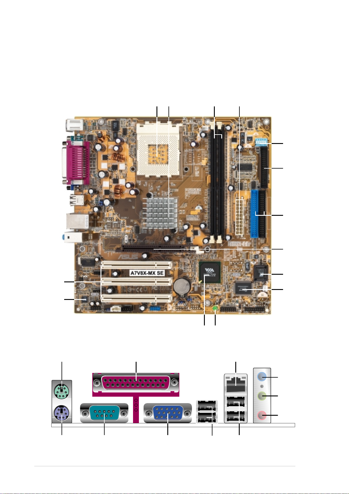
1.4 Motherboard components
321
11
4
7
14
6
8
13
5
9
10
12
15
25
18
19
20
21
16 17
2324
22
Before you install the motherboard, learn about its major components and
available features to facilitate the installation and future upgrades. Refer to the
succeeding pages for the component descriptions.
1-4
Chapter 1: Product introduction
1
CPU socket. Socket 462 (Socket A) Zero Insertion Force (ZIF) socket for
AMD Athlon XP™ up to 3200+ processors.
2
3
4
5
6
North bridge controller. The VIA KM400 North bridge controller chipset
supports a 64-bit DDR memory controller and up to 2 GB of
333/266/200MHz DDR memory. It also incorporates the fast
HyperTransport™ link to the CPU and supports AGP 8X technology. VIA
KM400 also features the VIA UniChrome™ 2D/3D graphics core for
efficient multimedia applications including DVD and video playback.
DDR DIMM sockets. The motherboard comes with two Double Data Rate
Dual Inline Memory Module (DDR DIMM) sockets to support up to 2GB of
system memory. This memory architecture allows data transfer rates of up
to 2.7 GB/s with PC2700 DDR DIMMs.
ATX power connector. This connects the standard 20-pin plug from the
power supply unit. The power supply unit must have at least 1A on the +5V
standby lead (+5VSB).
DIP switches. This 5-pin Dual Inline Package (DIP) switches allows you to
select the CPU frequency multiple.
Floppy disk drive connector. This connects the provided ribbon cable for
the floppy disk drive. One side of the connector is slotted to prevent
incorrect insertion of the floppy disk drive cable.
7
8
9
10
11
IDE connectors. These dual-channel bus master IDE connectors support
up to four UltraATA133, PIO Modes 0 ~ 4 IDE devices. Both the primary
(blue) and secondary (black) connectors are slotted to prevent incorrect
insertion of the IDE ribbon cable.
AGP slot. The Accelerated Graphics Port (AGP) slot supports 1.5V and
0.8V AGP 8X/4X mode AGP cards for graphics and multimedia
applications.
Flash EEPROM. This 2Mb Firmware Hub contains the programmable
BIOS program.
Super I/O chipset. The Winbond 83697HF I/O controller offers support for
a variety of I/O functions including two high-speed UART compatible serial
ports and one parallel port with EPP and ECP capabilities. The Super I/O
controller also supports a floppy disk drive, Game/MIDI port, PS/2
keyboard, and PS/2 mouse.
Onboard LED. This onboard LED lights up if there is a standby power on
the motherboard. This LED acts as a reminder to turn off the system power
before plugging or unplugging devices.
ASUS A7V8X-MX SE motherboard user guide
1-5

12
South bridge controller. The VIA VT8235 CE integrated South bridge
controller provides efficient bandwith requirements for PCI, USB and
support for LAN devices. This controller also supports standard
UltraATA133 IDE drives and provides separate data paths for each IDE
channel. The controller supports six USB ports, one LAN port and is PCI
2.2 compliant. The VIA VT8235 communicates with the North bridge chip
at rates of up to 533MB/s using the VIA 8X VLink Technology.
13
14
15
16
17
18
19
20
Audio CODEC. The ADI AD1980 6-channel Audio CODEC is AC’97
compliant and designed for PC multimedia systems.
PCI slots. These 32-bit PCI 2.2 expansion slots support bus master PCI
cards such as SCSI and LAN cards. The PCI slots operates at up to
133MB/s maximum output.
PS/2 mouse port. This green 6-pin connector is for a PS/2 mouse.
Parallel port. This 25-pin port connects a parallel printer, a scanner, or
other devices.
RJ-45 port. Using the South bridge integrated MAC and the VIA VT6103
LAN PHY Fast Ethernet controller, this port allows connection to a Local
Area Network (LAN) through a network hub.
Line In port. This Line In (light blue) port connects a tape player or other
audio sources. In a 6-channel mode, this port functions as Bass/Center.
Line Out port. This Line Out (lime) port connects a headphone or a
speaker. In a 6-channel mode, this port functions as Front Speaker Out.
Microphone port. This Mic (pink) port connects a microphone. In a
6-channel mode, this port functions as Rear Speaker Out.
21
22
23
24
25
USB 1 & 2 ports. These two 4-pin Universal Serial Bus 2.0/1.1 ports are
available for connecting USB devices such as mouse and PDA.
USB 3 & 4 ports. These two 4-pin Universal Serial Bus 2.0/1.1 ports are
available for connecting USB devices such as mouse and PDA.
VGA port. This 15-pin VGA port connects to a VGA monitor.
Serial port. This port connects a serial mouse. modem or other serial
devices.
PS/2 keyboard port. This purple 6-pin connector is for a PS/2 keyboard.
1-6
Chapter 1: Product introduction
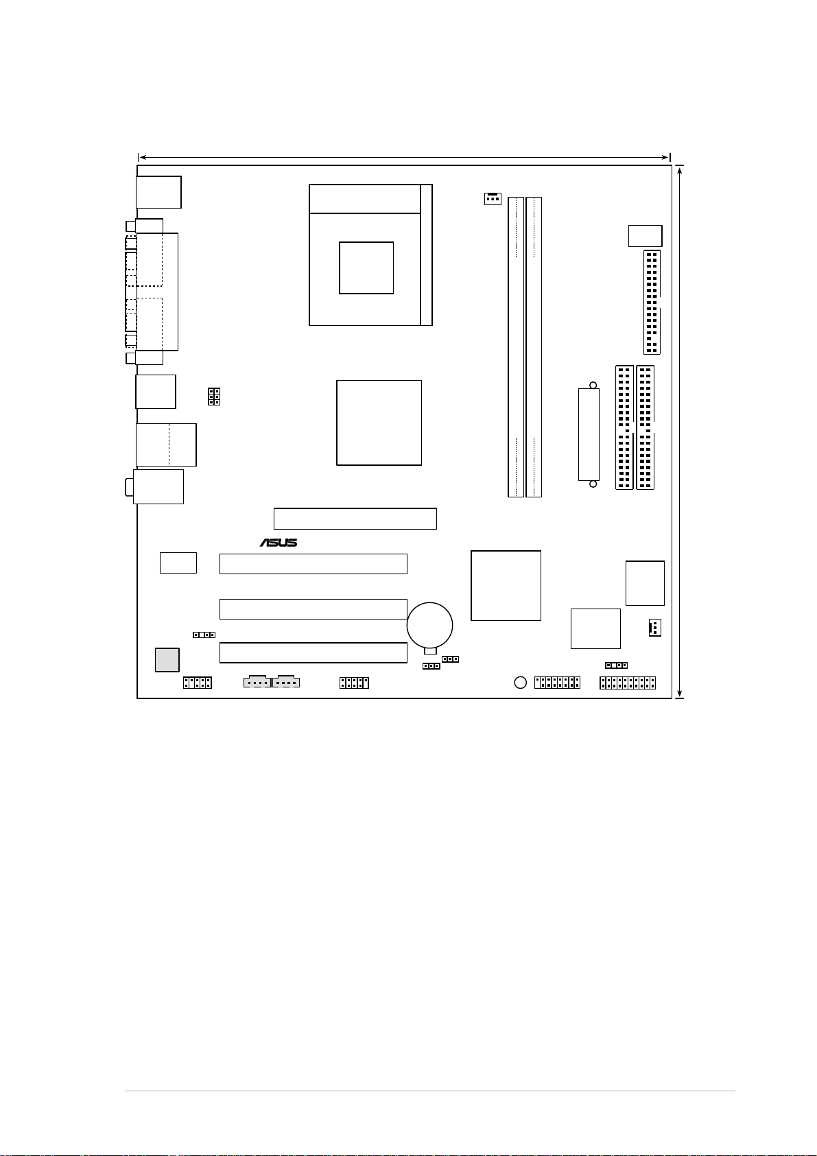
1.5 Motherboard layout
24.5cm (9.6in)
PCI1
PANEL
A7V8X-MX SE
®
CR2032 3V
Lithium Cell
CMOS Power
CD1AUX1
Super
I/O
2Mbit
Firmware
Hub
PS/2KBMS
T: Mouse
B: Keyboard
Below:Mic In
Center:Line Out
Top:Line In
Accelerated Graphics Port (AGP1)
CPU_FAN
FP_AUDIO
AD1980
CODEC
USB2.0
T: USB3
B: USB4
Top:
RJ-45
GAME
CLRTC
FLOPPY
PRI_IDE
SEC_IDE
CHASSIS
ATX Power Connector
DDR DIMM1 (64 bit,184-pin module)
DDR DIMM2 (64 bit,184-pin module)
CHA_FAN1
USB1
USB2
USB56
SB_PWR
24.5cm (9.6in)
USBPWR12
USBPWR34
USBPWR56
PARALLEL PORT
COM1
VGA1
PCI2
PCI3
VIA
VT8235CE
Socket 462
VIA
KM400
DSW
SPDIF
VIA
VT6103
ASUS A7V8X-MX SE motherboard user guide
1-7
1.6 Motherboard installation
The A7V8X-MX SE uses the Micro ATX form factor, measuring 24.5 cm (9.6 in.) x
24.5 cm (9.6 in.) - a standard fit for most Micro ATX chassis.
WARNING! Unplug the power cord before installing the motherboard. Failure to
do so may cause you physical injury and damage Motherboard components.
1.6.1 Placement direction
When installing the motherboard to the chassis, make sure to place it in the correct
orientation. The edge with external ports goes to the rear part of the chassis as
indicated in the image below. It may be more convenient to install major cables,
the CPU and modular components before fixing the motherboard inside the case
frame.
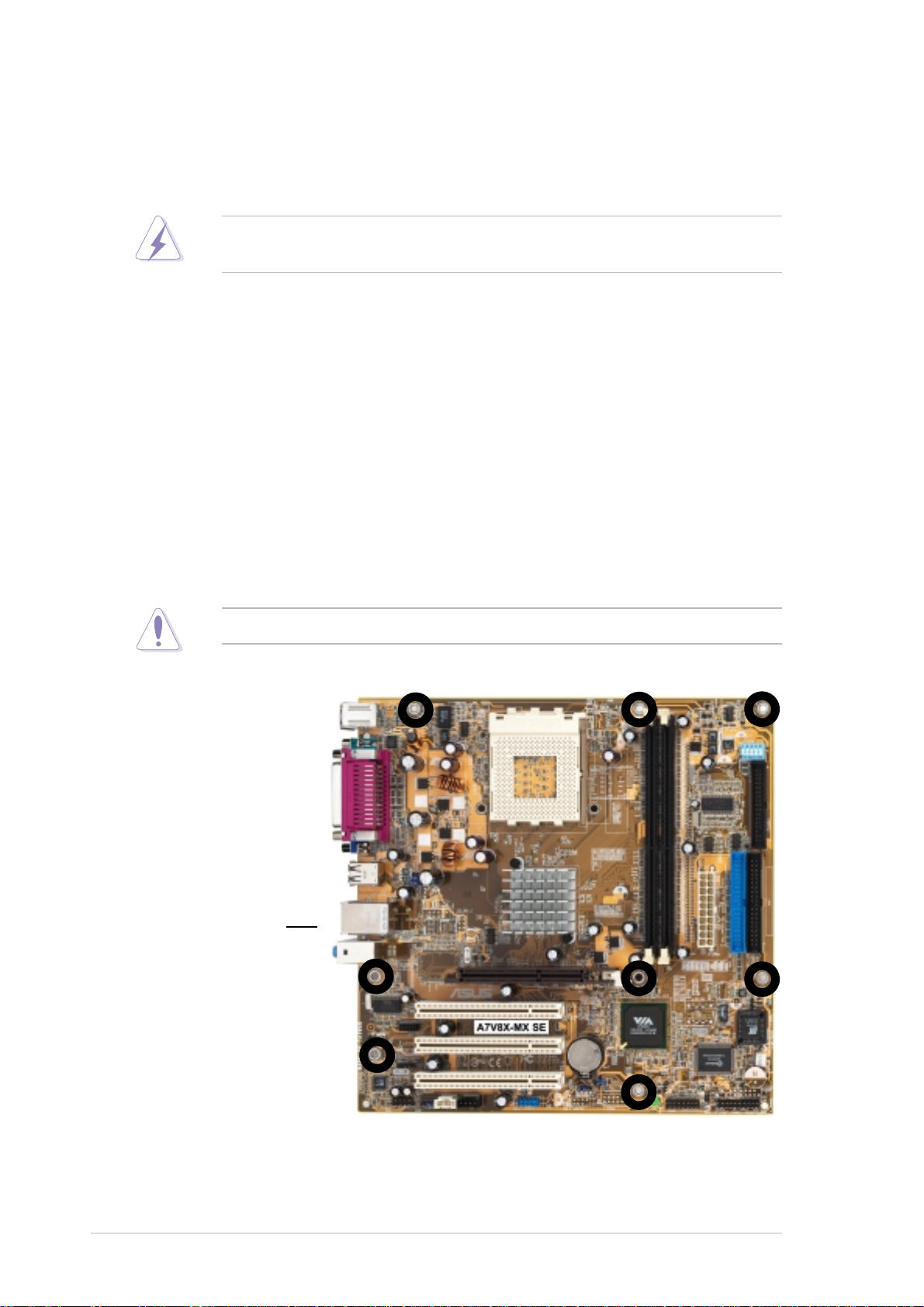
1.6.2 Screw holes
Place eight (8) screws into the holes indicated by circles to secure the
motherboard to the chassis.
Do not overtighten the screws! Doing so may damage the motherboard.
Place this side
towards the rear of
the chassis
1-8
Chapter 1: Product introduction
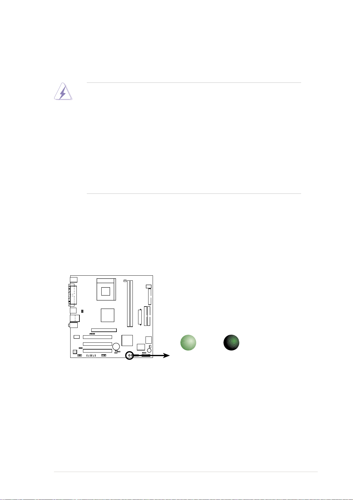
1.7 Before you proceed
A7V8X-MX SE
®
A7V8X-MX SE Onboard LED
SB_PWR
ON
Standby
Power
OFF
Powered
Off
Take note of the following precautions before you install motherboard components
or change any motherboard settings.
1. Unplug the power cord from the wall socket before touching any
component.
2. Use a grounded wrist strap or touch a safely grounded object or to a metal
object, such as the power supply case, before handling components to
avoid damaging them due to static electricity.
3. Avoid touching the ICs on components.
4. Whenever you uninstall any component, place it on a grounded antistatic
pad or in the bag that came with the component.
5. Before you install or remove any component, ensure that the ATX
power supply is switched off or the power cord is detached from the
power supply. Failure to do so may cause severe damage to the
motherboard, peripherals, and/or components.
Onboard LED
The A7V8X-MX SE motherboard comes with a standby power LED. When lit, this
green LED (SB_PWR) indicates that the system is ON, in sleep mode, or in soft-off
mode, a reminder that you should shut down the system and unplug the power cable
before removing or plugging in any motherboard component.
ASUS A7V8X-MX SE motherboard user guide
1-9
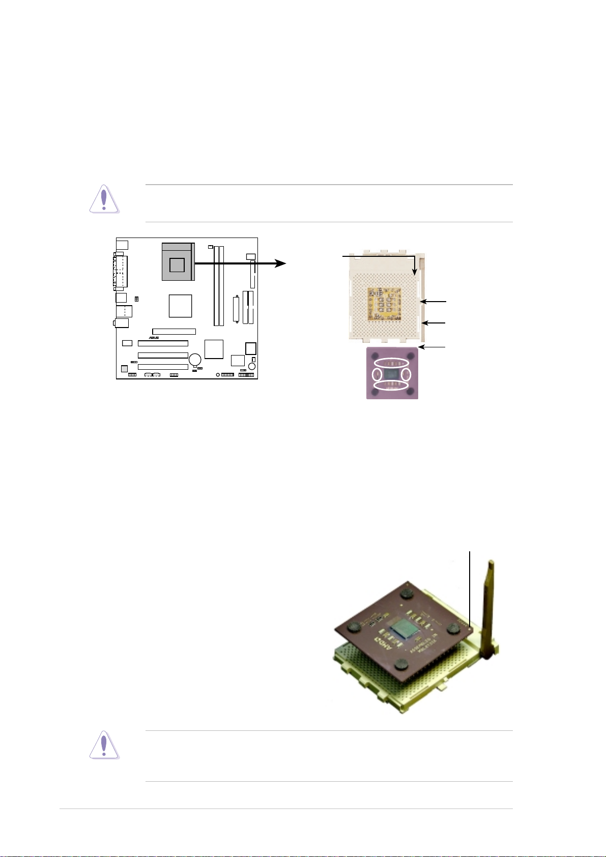
1.8 Central Processing Unit (CPU)
A7V8X-MX SE
®
A7V8X-MX SE Socket 462
AMD™ CPU
CPU NOTCH
LOCK
CPU NOTCH
TO INNER
CORNER
LEVER
The motherboard provides a Socket A (462) for CPU installation. The A7V8X-MX
SE supports Athlon™ XP processors with “QuantiSpeed” data processing, large
data caches, 3D enhancements and 333/266/200MHz bus speeds. AMD Athlon™
XP processors offer gigahertz speeds to support all the latest computing platforms
and applications.
This motherboard does not support AMD processors with less than 1GHz core
speed.
Each AMD CPU has a “marked” corner. This corner is usually indicated with a
notch, and/or a golden square or triangle. Refer to this indicator while orienting
the CPU. A fan and heatsink should be attached to the CPU to prevent
overheating.
Installing the CPU
Follow these steps to install a CPU:
1. Locate the Socket 462 and open it by
pulling the lever gently sideways away
from the socket. Then lift the lever
upwards. The socket lever must be fully
opened (90 to 100 degrees).
2. Insert the CPU with the correct
orientation. The notched or golden
corner of the CPU must be oriented
toward the inner corner of the socket
base nearest to the lever hinge.
Golden corner
1-10
The CPU should drop easily into place. Do not force the CPU into the socket
to avoid bending the pins. If the CPU does not fit, check its alignment and look
for bent pins.
Chapter 1: Product introduction
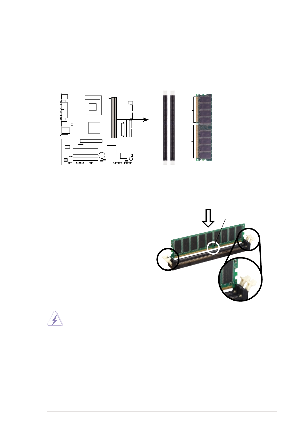
1.9 System memory
A7V8X-MX SE
®
A7V8X-MX SE
184-Pin DDR DIMM Sockets
80 Pins104 Pins
DIMM1
DIMM2
The motherboard has two Double Data Rate (DDR) DIMM sockets that supports
up to 2GB non-ECC PC2700/2100/1600 DDR SDRAM DIMMs. Each DIMM socket
is double-sided. DIMMs come in combinations of single or double-sided types
ranging through 64MB, 128MB, 256MB, 512MB, and 1 GB.
Installing a DIMM
1. Unlock a DIMM socket by pressing
the retaining clips outward.
2. Align a DIMM on the socket. Make
sure the notches on the DIMM
exactly match the notches in the
socket.
3. Firmly insert the DIMM into the
socket until the retaining clips lock
into place.
A DDR DIMM is keyed with a notch so that it fits in only one direction. DO NOT
force a DIMM into a socket to avoid damaging the DIMM.
DDR DIMM notch
Unlocked retaining clip
ASUS A7V8X-MX SE motherboard user guide
1-11
1.10 Expansion slots
The A7V8X-MX SE motherboard has three (3) PCI slots and one (1) Accelerated
Graphics Port (AGP). The following sub-sections describe the slots and the
expansion cards that they support.
1.10.1 Configuring an expansion card
Some expansion cards need an IRQ to operate. Generally, an IRQ must be
exclusively assigned to one function at a time. In a standard design configuration,
16 IRQs are available but most are already in use.
Normally, 6 IRQs are free for expansion cards. Sometimes IRQs are “shared” by
more than one function; in this case, IRQ assignments are swapped automatically
or adjusted through the BIOS firmware.
Standard Interrupt Assignments
IRQ Standard Function
0 System Timer
1 Keyboard Controller
2 Programmable Interrupt Controller
3* USB Universal Host Controller
4* Communications Port (COM1)
5* Onboard Audio
6 Standard Floppy Disk Controller
7* Printer Port (LPT1)
8 System CMOS/Real Time Clock
9* Onboard LAN
10* USB Universal Host Controller
11* Onboard VGA
12* PS/2 Compatible Mouse Port
13 Numeric Data Processor
14* Ultra A T A Controller
15* Secondary Ultra ATA Controller
* These IRQs are usually available for ISA or PCI devices.
IRQ assignments for this motherboard
ABC
PCI slot 1 shared –– ––
PCI slot 2 –– shared ––
PCI slot 3 –– –– shared
AGP slot shared –– ––
1-12
Chapter 1: Product introduction
 Loading...