

Page 1

Disassembly procedure
A
Chapter
Disassembly Procedure
Please follow the information provided in this section to perform the
complete disassembly procedure of the notebook. Be sure to use
proper tools described before.
SUS A7T Series Notebook consists of various modules. This chapter describes the
procedures for the complete notebook disassembly. In addition, in between
procedures, the detailed disassembly procedure of individual modules will be
provided for your service needs.
The disassembly procedure consists of the following steps:
• Battery Module
• HDD Module
• Wireless LAN Module
• TV Tuner Module
• Second Memory Module
• CPU Module
• ODD Module
• Keyboard
• Main Memory Module
• Top Case Module
• LCD Module
• Bottom Case Module
• Motherboard Module
2 - 1
Page 2
Disassembly procedure
BATTERY
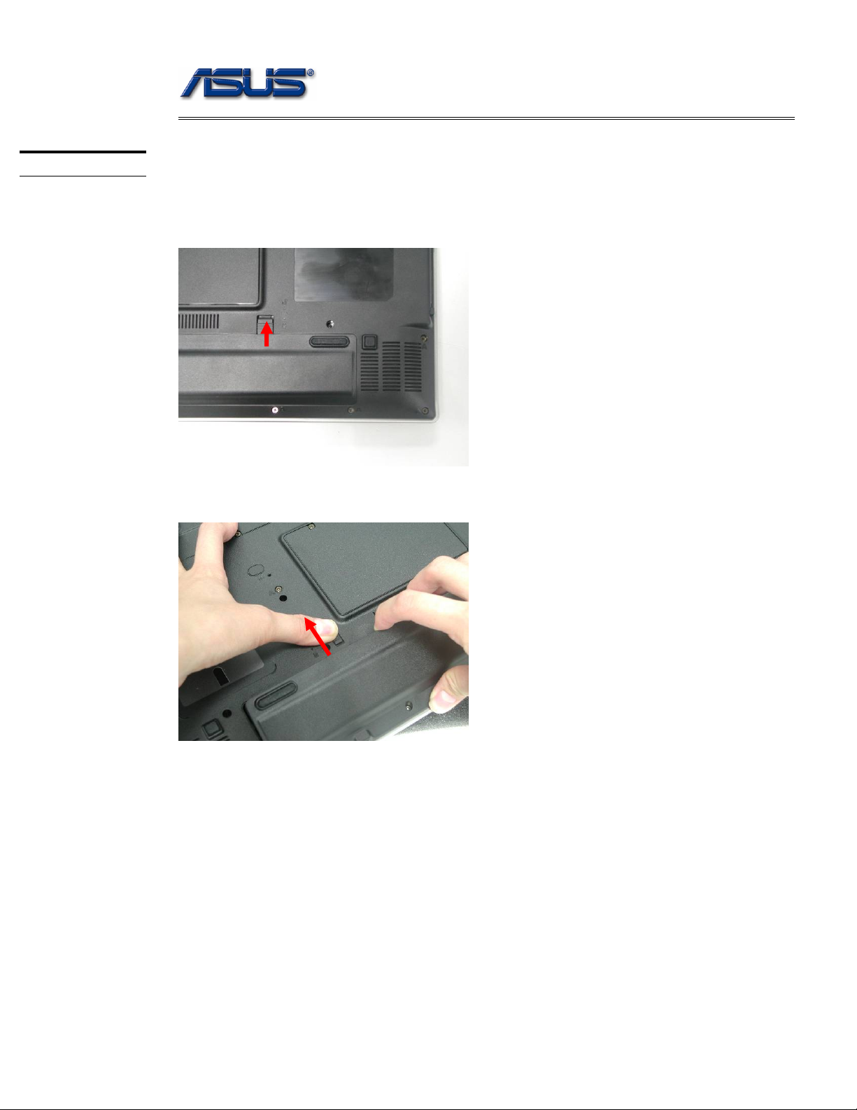
Battery Module
The illustration below shows how to remove the battery module.
1. Turn over the notebook. Unlock the battery lock (No.1).
1
2. Slide the battery lock (No.2) and pull the battery pack out.
2
2 - 2
Page 3
Disassembly procedure
HDD MODULE
HDD MODULE
REMOVAL
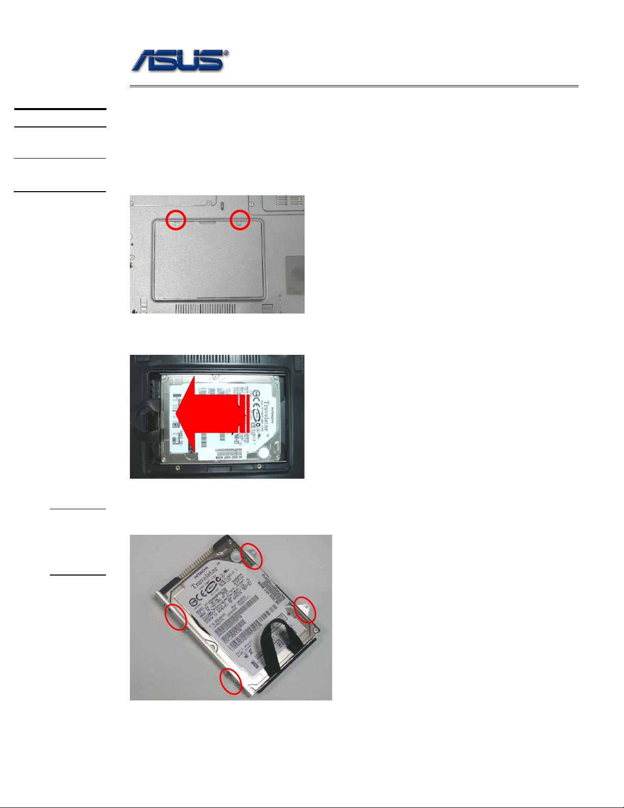
HDD Module
The illustrations below show how to remove the HDD module from the notebook.
Removing HDD Module
1. Remove 2 screws [M2 * 4(L)] here. And lift the cover away.
2. Pull out the hard drive and lift the hard drive away.
HDD
MODULE
DISASS
EMBLY
Disassembling HDD Module
Remove 4 screws [M3 * 4(L)]] to separate HDD from HDD housing.
2 - 3
Page 4
Disassembly procedure
WIRELESS
LAN
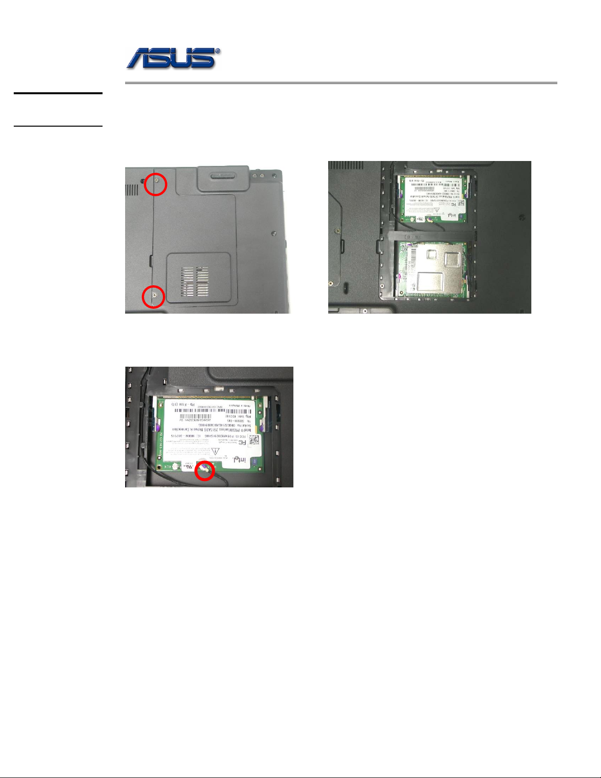
Wireless LAN Module
The illustration below shows how to remove the Wireless LAN module.
1. Remove 2 screws [M2 * 4(L)] and remove the Mini-PCI Cover away.
MINI-PCI
TV TUNER
2. Disconnect the main Antenna and open the two latches to pop the MINI PCI
MODULE up then pull it out.
2 - 4
Page 5
Disassembly procedure
TV TUNER
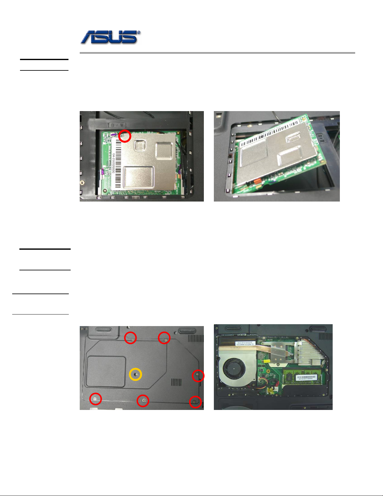
TV TUNER Module
The illustration below shows how to remove the TV TUNER module.
1. Disconnect the RF cable and open the two latches to pop the TV TUNER
module and remove the TV TUNER module from the mini-PCI socket.
MEMORY
MODULE
MEMORY
REMOVAL
Second Memory Module
The A7T Series Notebook has two expansion SO-DIMM slots for you to upgrade the total
memory up to 2GB with two DDR2-533 1024 MB SO-DIMM RAM modules, here
introduce you the second memory slot.
Removing Memory module
1. Remove 6 screws [M2 * 4(L)] & 1 screw [M2 * 8(L)] and take the CPU door
away.
M2*4(L)
M2*8(L)
2 - 5
Page 6
Disassembly procedure
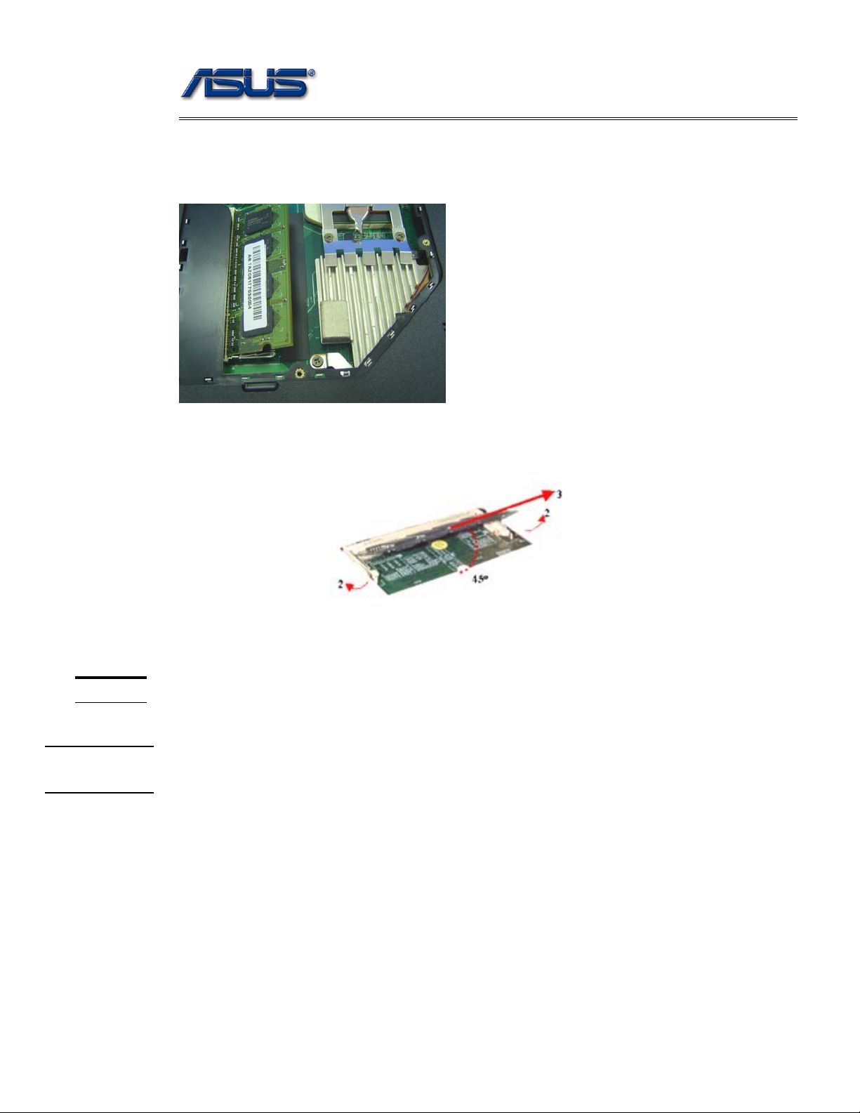
2. Remove the Memory module by opening the latches which will pop the
module up to a 45° angle and then pulling out the module.
3. If there is an existing memory, remove it by opening the latches(No. 2),
which will pop the module up to a 45° angle, and then pulling out the
module in that angle (No. 3).
REMOVAL
CPU
CPU
CPU Module
The illustrations below show how to remove the CPU module from the notebook.
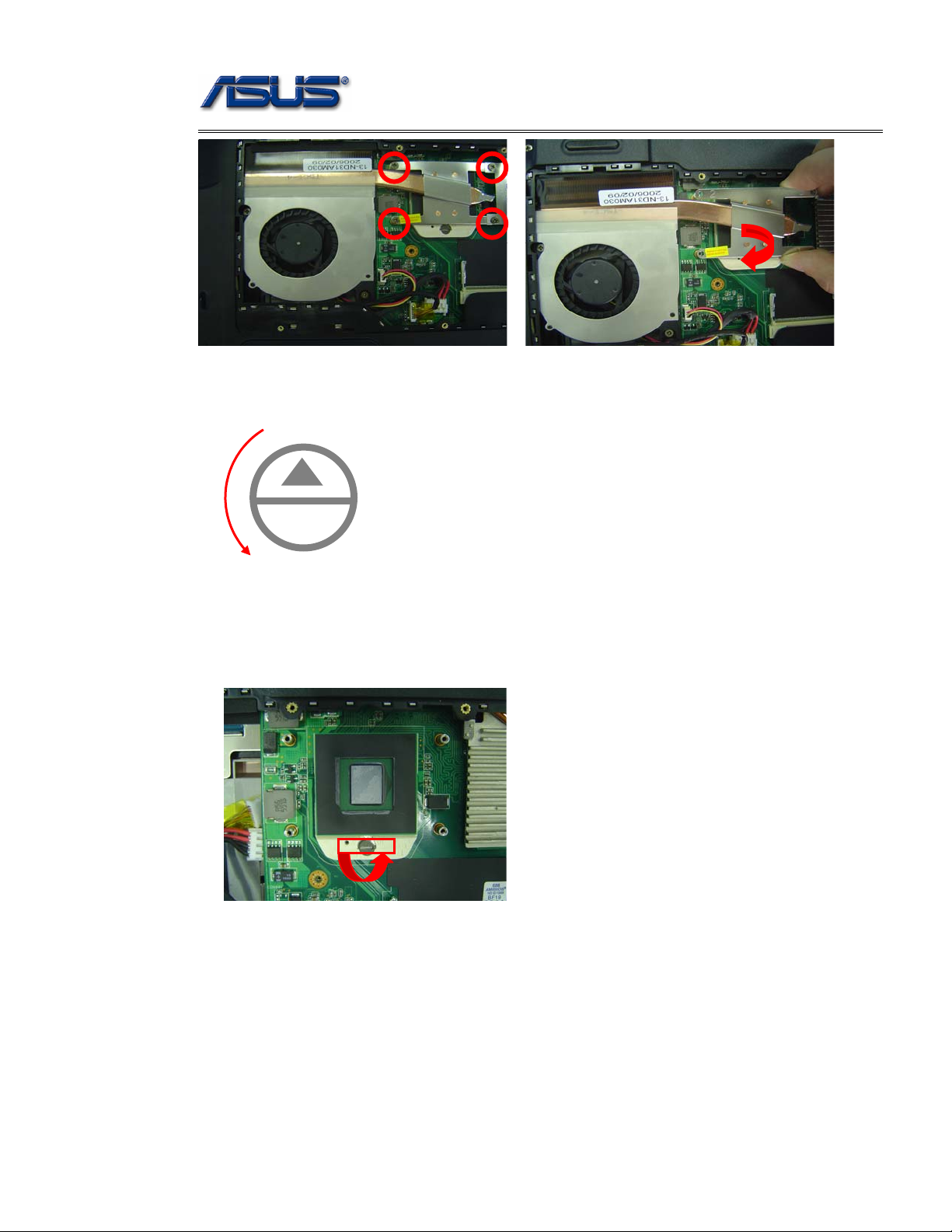
Removing CPU
1. Remove 4 screws [M2 *4(L)] by order and take the CPU heat sink module
away.
2 - 6
Page 7
Disassembly procedure
2. Turn the non-removable screw 180 degrees counter-clockwise to loosen
the CPU. Squeeze the vacuum handling pump and use it to lift the CPU
away.
Unlock
L
O
3. Don’t touch the die above the CPU.
4. Remove the CPU away.
5. Remove CPU thermal pad from CPU die with a pair of tweezers.
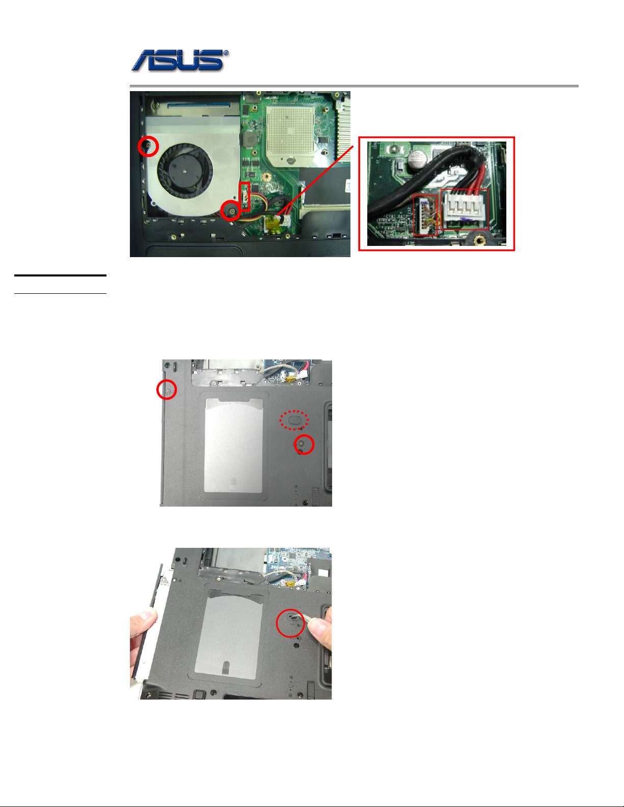
6. Remove 2 screws [M2 *3(L)] and disconnect the fan cable & DC-in cable
& Bluetooth cable, and then take the FAN module away.
2 - 7
Page 8
Disassembly procedure
ODD MODULE
ODD Module
The illustration below shows how to remove the ODD module.
1. Remove the rubber and remove 2 screws [M2 * 4(L)] from the bottom
case.
2. Put the screw driver here and push the ODD drive out from the NB.
2 - 8
Page 9

KEYBOARDDI
SASSEMBLY
K/B
REMOVAL
Disassembly procedure
Keyboard
The illustration below shows how to remove the keyboard
Removing Keyboard
1. Push the 3 latches in with a pair of tweezers or a single-slotted
screwdriver and lift the keyboard up.
2. Lay the keyboard down over the touch pad module. Do not remove the
keyboard yet. The keyboard FPC is still attached.
CABLE
REMOVAL
Removing Keyboard Cable
Use a flexible connector tool to unlock the cable connector on both ends
Carefully pull out the keyboard cable with a pair of tweezers.
Lock the connector again to avoid possible breakage
Remove Keyboard from the top case.
3. Disconnect the keyboard FPC and remove the keyboard.
2 - 9
Page 10

MEMORY
MODULE
MEMORY
REMOVAL
Disassembly procedure
Main Memory Module
The A7T Series Notebook has two expansion SO-DIMM slots for you to upgrade the total
memory up to 2GB with two DDR2-533 1024 MB SO-DIMM RAM modules, here
introduce you the main memory slot.
Removing Memory module
1. Remove 1 screws [M2 * 4(L)] and take the DIMM door away.
2. Remove the Memory module by opening the latches which will pop the
module up to a 45° angle and then pulling out the module.
2 - 10
Page 11

Disassembly procedure
TOP CASE
MODULE
TOP CASE
MODULE
REMOVE
T op Case Module
The illustrations below show how to disassemble and remove the top case module of the
notebook. The module contains the top case itself and touch pad module.
Removing Top Case Module
1. Remove 2 screws [M2 * 4(L)] (back - coaxial cable cover) and carefully
remove the Cable Cover.
2. Remove 2 screws [M2 * 4(L)] and disconnect the Coaxial cable & Inverter
cable with tweezers.
3. Carefully pull out the Antenna from the bottom case.
2 - 11
Page 12

Disassembly procedure
Inverter cable Coaxial cable
4. Remove 2 screws [M2.5 * 8(L)] on rear side.
5. Remove 2 screw [M2 * 6(L)] and carefully remove the hinge cover on the
both side.
6. Remove 2 screws [M2.5 * 8(L)] to unloosen the hinge.
2 - 12
Page 13

Disassembly procedure
7. Remove 4 screws [M2.5 * 8(L)] on the Bottom case.
8. Separate LCD Module from the Top case module.
2 - 13
Page 14

Disassembly procedure
9. Remove 8 screws [M2 * 4(L)] on the top case.
10. Disconnect the speaker cable & Touch pad FPC & Audio FPC & Launch BD
FPC from the motherboard.
Speaker cable
Touchpad FPC
Launch BD
Audio FPC
2 - 14
Page 15

Disassembly procedure
11. Turn over the NB and remove 1 screws [M2 * 8(L)] & 8 screws [M2 * 6(L)] on
the bottom case.
M2*8L
M2*6L
12. Remove 3 screws [M2 * 3(L)] on the bottom case.
13. Remove 8 screws [M2 * 4(L)] on the bottom case.
2 - 15
Page 16

Disassembly procedure
14. Now you can separate the Top case from the Bottom case.
TOUCH
PAD
MODULE
REMOVE
Removing Touch Pad Module
1. Remove 6 screws [M2 * 3(L)] and disconnect the Touch pad board FPC with
tweezers then take away the Touch pad bracket from the top case.
2. Separate the Touch pad board from the Touch pad bracket.
2 - 16
Page 17

LAUNCH BD
MODULE
REMOVE
Disassembly procedure
Removing LAUNCH BD. module
1. Remove 1 yellow mylar and disconnect the FPC.
2. Remove 4 screws [M2 * 4(L)] and take away the Launch BD. module.
AUDIO BOARD
MODULE
REMOVE
Removing Audio board module
1. Remove 2 yellow mylar and disconnect the FPC.
2. Remove 2 screws [M2 * 4(L)] and take away the Launch BD. module.
2 - 17
Page 18

SPEAKER
MODULE
REMOVE
Disassembly procedure
Removing Speaker module
1. Remove 6 screws [M2 * 4(L)] on the both side.
2. Remove 2 yellow mylar and take away the both speaker module.
2 - 18
Page 19

Disassembly procedure
LCD
MODULE
LCD
DISASSEMBLY
LCD Module
The illustrations below show how to remove and disassemble the LCD module. The
module contains LCD panel, inverter board, LCD hinge bracket, hinge cover, LCD front
cover, and LCD back cover.
Disassembling LCD Module
1. Remove 8 rubber pads. And then 8 screws [M2.5 * 8(L)] underneath them.
Please do not disassemble the individual parts.
2. Carefully pry the inside edges of the LCD front bezel and remove the LCD
front cover.
2 - 19
Page 20

Disassembly procedure
3. Remove 2 screws [M2.5 * 5(L)] and disconnect the coaxial cable & LCD
cable then remove the inverter board.
4. Remove 2 screws [M2.5 * 8(L)] and remove the LCD bottom bracket from the
LCD cover.
5. Remove 2 screws [M2 * 5(L)] and remove the LCD module from the LCD
back covert.
2 - 20
Page 21

Disassembly procedure
6. Remove 4 screws [M2* 3(L)] & 4 screws on th e other side.
7. Remove 1 yellow tape and disconnect the coaxial cable from LCD.
8. Remove 1 yellow tape and remove CCD module then disconnect the CCD
cable.
2 - 21
Page 22

Disassembly procedure
9. Remove 2 screws [M2.5 * 5(L)] and remove the Top LCD bracket from the
LCD cover.
10. Remove 1 screw [M2.5 * 5(L)] & 2 screws [M2.5 * 8(L)] on the both side.
11. Remove the LCD Hinges from LCD back cover on both sides.
M2.5* 5L M2.5* 5L
M2.5* 8L M2.5* 8L
2 - 22
Page 23

BOTTOM
CASE
MODULE
MOTHERBOARD
REMOVAL
Disassembly procedure
Bottom Case Module
The illustrations below show how to disassemble and remove the bottom case module of the
notebook. The module contains the bottom case itself, speaker sets and Motherboard.
Removing Motherboard
1. Remove 3 yellow mylar and disconnect the speaker cable then remove
the both speaker module.
2. Remove 6 screws [M2 * 6(L)] on the M/B.
2 - 23
Page 24

Disassembly procedure
3. Remove the motherboard from the bottom case.
4. Remove 1 screw [M2 * 4(L)] and remove DC-IN bracket.
5. Remove 1 screw [M2 * 4(L)] and remove the bracket then disconnect the
cable and remove the Bluetooth board.
2 - 24
Page 25

Disassembly procedure
MOTHERBOARD
MODULE
Motherboard Module
Removing Modem Module
1. Remove 4 tapes and remove 2 screws [M2 * 4(W)] and disconnect the
cable then take away the modem module.
2. Remove 3 screws [M2 * 4(W)] and take away the VGA thermal module.
2 - 25
 Loading...