

Asus A7Sv User Manual

Software Specification
Chapter
Software Specifications
Get to know more about the A7Sv series Notebook with a detailed look at the software
specifications.
T
he information contained in the chapter can be quite useful when y ou are
troubleshooting the system’s hardware. Each item has its individual usage for you to
Und
erstand the software side of the notebook’s architectu re.
6-1

Software Specification
1. BIOS Version Naming Rule
BIOS Version Format : RNN
Table 1 BIOS Revision Code Format
CHARACTER DEFINITION DESCRIPTION
R Major
version
NN Minor
version
0 = SR (sample run) phase,
1 = ER (engineer run) phase,
2 = PR (pilot-run) and MP (mass-production) phases
T = Test Version, which is for unofficial verification.
The test BIOS will not be released officially and uploaded to BIOS
folder of NB sever.
9 = Test Version, used in case of test BIOS over xxxxxxxx.T99,
The next version of test BIOS will be xxxxxxxx.900
Note: minor version of test BIOS is counting sequentially.
9 – Test Version, used in case of test BIOS over xxxxxxxx.T99,
The next version of test BIOS will be xxxxxxxx.900。
00~99
6-2

Software Specification
2. BIOS Schedule
Table 2 BIOS Development Schedule
Stage BIOS Revision Release date
Bring UP
SR
PR
000 2007/04/26
001
002 2007/05/17
200 2007/05/25
201 2007/06/28
202 2007/07/09
2007/05/04
6-3

Software Specification
3. Documentation
1. BIOS Engineering Specification, and update should be provided in the beginning of each st age.
2. BIOS Validation Items should be provided in the end of S/R stage.
3. BIOS Implementation Checklist should be provided before S/R stage and should be updated on each S/R
bios release.
6-4
Software Specification
4. POST
4.1 ASUS Logo
4.1.2 With ASUS BIOS
The ASUS animation logo should be displayed during POST like below.
4.1.2 With General BIOS
If there is no OEM logo like ASUS/Hitachi/Epson/Haier displayed during POST. The intel OSB
should be displayed on the center of screen.
4.2 ASUS Instant On Logo
Boot from Instant ON button or CIR, and the ASUS instant on logo should be displayed durin g POST
like below.
4.3 intel OSB
intel OSB (On-Screen Branding) should follow the intel spec.
If there is an OEM logo like ASUS/Hitachi/Epson/Haier displayed during POST. The intel OSB should be
displayed on the right-bottom of screen.
6-5
Software Specification
4.2 Prompt Message
During ‘Quiet Boot’, the prompt string like “<F2> : Enter Setup, <ESC> : Popup Menu” should be
displayed on the left-bottom of screen.
4.3 Hotkey Functions during BIOS POST
Table 4 Hotkey List
Button Description
Esc Press Esc Key during post stage, the system will pop up a boot menu.
Tab Press Tab key during post stage, the normal post will become Text Mode POST
F2 Press F2 key during post stage, the system will enter into BIOS Setup Menu.
F4
F9 Press F9 during post stage, the system will start the Recovery Capability up.
F12
Fn + F5 Press Fn+F5 to decrease the brightness of LCD backlight.
Fn + F6 Press Fn+F6 to increase the brightness of LCD backlight.
Press F4 key during post stage, the system will open the easy flash utility.
The generic version of bios doesn’t support this function.
Press F12 key during post stage, the system will boot from network if the Onboard
LAN Boot ROM function under BIOS setup menu is enabled.
4.4 Beep Sound
There is no warning beep sound allowed during POST.
4.5 POST Wave
POST Wave sound should be played during POST, and the sound volume could be adjusted in the setup
menu.
4.6 Text Mode POST (Diagnostic Mode)
The following items should be displayed during text mode POST.
z BIOS Date, Version
EX : BIOS Date: 07/09/2007 Ver: 202
z CPU Information, speed, type
EX : CPU : Intel® Core™ 2 DUO CPU T5250 @ 1.50GHz
Current Speed : 1.50GHz
z Memory size & Information (Not include VGA sh ared memory)
The MCH is operating with DDR2 667/CL5 in Single-Channel Mode
EX : 1024MB
6-6

Software Specification
z USB Devices (Detected by BIOS during POST.)
EX : USB Device(S) : 1 Keyboard, 1 Hub
z Hard drive information
The IDE Device will be detected automatically.
EX : Auto-Detecting Pri Master .. IDE Hard Disk
Auto-Detecting 3rd Master ... ATAPI CDROM
Pri Master : HTS541616J9SA00 SB40C7OP
Ultra DMA Mode-5, S.M.A.R.T. Capable and Status OK
3rd Master : MATSHITADVD-RAM UJ-850S 120
Ultra DMA Mode-2
z USB mass storage devices detection
EX : Auto-detecting USB Mass Storage Devices ..
00 USB mass storage devices found and configured.
z Other information.
Hotkey prompt :
EX : Press F2 to run Setup
Press F12 if you want to boot from the network
(The “Onboard LAN Boot ROM” function under BIOS setup menu should be enabled.)
Press Esc for BBS POPUP
6-7

Software Specification
5. SETUP Menu
Refer to the A7Sv_BIOS_Setup_Menu_Specification_Draft.DOC
6-8

Software Specification
6. Boot Devices Support
The system supports the following bootable devices,
z HDD
z ODD (CD-ROM/ DVD-ROM …)
z LAN (PXE server)
z USB Mass Storage (USB CDROM/ Floppy/ Flash Disk…)
6.1 Boot Device Selection by Recovery CD Command
Refer to the Boot Device Selection 0.3.doc.
6-9

Software Specification
7. Audio
7.1 PCBEEP
A7Sv supports PCBEEP sound and the volume of audio sound is 40 db under DOS mode.
There is no sound allowed while plug in/out USB devices.
There is no sound during POST.
7.2 POSTWAVE
During the POST the A7Sv supports the POSTWA VE, and the user can enable, disable or modify the
volume under BIOS setup menu.
6-10

Software Specification
8. EXTF/*BBSS* Interface & Utilities
The bios should support EXTF and *BBSS* interfaces for the following functions.
8.1 AFLASH2
z Automatic : The BIOS ROM will be flashed automatically without any prompt.
Usage :
Aflash2.exe /auto:filename
z Manual
Usage :
Aflash2.exe
8.2 EasyFlash
Refer to the A7Sv_BIOS_Setup_Menu_Specification_Draft.DOC - Chapter 2-2 Start Easy
Flash
8.3 ROMWRT
A7Sv supports Rom Write function, there are some spaces reserved for factory using. But product
engineer (PE) needs to use different utility to write data into those areas by different customer’s
requirement.
8.4 WDMI
A7Sv supports WDMI utility, the DMI information can be accessed under windows.
8.5 WINFlash
A7Sv support winflash function. The user can update bios under ACPI-OS.
The system needs to reboot after the bios is updated.
6-11

Software Specification
9. BIOS Crisis Recovery
9.1 Auto Crisis Recovery (Generic Version does not support this feature)
If bios checksum is not correct, the bios crisis recovery will be invoked automatically. However, there
should be one bios image existed in the hard disk and named as ‘A7Sv.BIN’.
9.2 Manual Crisis Recovery
Before invoking the bios crisis recovery, there should be one bios image existed in the hard disk and
named as “A7Sv.BIN”. The combination hotkey “CTRL+HOME” is used to invoke the bios crisis recovery
during bootblock and POST. If the hotkey is pressed in bootblock, the bios crisis recovery will be invoked
during POST. If the hotkey is pressed during POST, the system will reboot automatically and the bios
crisis recovery will be invoked on the next time of POST.
6-12

Software Specification
10. ATK Interface & Functions
BIOS should support ATK interface which defined by driver team for the following functions.
10.1 ASUS OSD (On-Scre en Display)
While pressing the following combination hotkey, the system will pop up an illustration on the left-top
corner of the screen to indicate the function is invoked.
Table 10 ASUS OSD List
Button Description
Fn+F2 The OSD for wireless console display and wireless device will be displayed.
Fn+F5 The OSD for brightness up will be displayed.
Fn+F6 The OSD for brightness down will be displayed.
Fn+F7 The OSD for LCD back light ON/OFF will be displayed.
Fn+F8
Fn+F9 The OSD for Touch Pad ON/OFF will be displayed.
Fn+F10 The OSD for volume mute will be displayed.
Fn+F11 The OSD for volume down will be displayed.
Fn+F12 The OSD for volume up will be displayed.
Fn+Space The OSD for Power4Gear mode will be displayed.
TouchPad
On/Off
Splendid The OSD for Color Enhancement will be displayed
Power4Phone The OSD for Power4Phone will be displayed.
Power4Gear The OSD for Power4Gear mode will be displayed.
10.2 ASUS Power4Gear
BIOS should support ASUS Power4Gear by pressing the Power4Gear button.
The OSD for display switch will be displayed. The last OSD displayed will
decide the final state which display should be switched to.
The OSD for Touch Pad ON/OFF will be displayed.
10.3 ASUS Power4Phone
BIOS should support ASUS Power4Phone by pressing Power4Phone button or Fn+Space..
10.4 ASUS Color Enhancement
BIOS should support Color Enhancement by pressing Splendid button.
6-13

Software Specification
10.5 ASUS TouchPad
BIOS should support TouchPad On/Off by pressing TouchPad On/Off button or Fn+F9.
10.6 ASUS Key Define
A7Sv doesn’t support this feature.
10.7 ASUS Mail LED
A7Sv doesn’t support this feature.
10.8 ASUS TouchPad LED
A7Sv doesn’t support this feature.
6-14

Software Specification
11. ACPI Tables
RSDP OEMID ACPIAM
RSDT
FACP
APIC
MCFG
OEMID _ASUS_
OEM Table ID Notebook
OEM Revision 0x05000710
Creator ID “MSFT“ (0x5446534d)
Creator Revision 00000097
OEMID “A M I” (0x2049204d2041)
OEM Table ID “OEMFACP” (0x20504341 464d454f)
OEM Revision 0x05000710
Creator ID “MSFT“ (0x5446534d)
Creator Revision 00000097
OEMID “A M I” (0x2049204d2041)
OEM Table ID “OEMAPIC” (0x20434950414d454f)
OEM Revision 0x05000710
Creator ID “MSFT“ (0x5446534d)
Creator Revision 00000097
OEMID “A M I” (0x2049204d2041)
BOOT
OEMB
OEM Table ID “OEMMCFG” (0x204746434d4d454f)
OEM Revision 0x05000710
Creator ID “MSFT“ (0x5446534d)
Creator Revision 00000097
OEMID “A M I” (0x2049204d2041)
OEM Table ID “OEMBOOT” (0x2049204d2041)
OEM Revision 0x05000710
Creator ID “MSFT“ (0x5446534d)
Creator Revision 00000097
OEMID “A M I” (0x2049204d2041)
OEM Table ID “AMI_OEM” (0x204d454f5f494d41)
OEM Revision 0x05000710
Creator ID “MSFT“ (0x5446534d)
Creator Revision 00000097
OEMID “A7Sv00” (0x003030533741) DSDT
OEM Table ID “A7Sv00000” (0x3030303030533741)
6-15

Software Specification
OEM Revision 0x00000000
Creator ID “INTL” (0x4c544e49)
Creator Revision 20051117
6-16

Software Specification
12. Power Management
12.1 Sleep States
BIOS supports S3, S4 and S5 states.
12.2 Wake Up Events
BIOS supports the following wake-up events.
z Wake up by pressing Power Button.(S3, S4, S5)
z Wake up by pressing any key.(S3)
z Wake up form USB keyboard/mouse.(S3)
z Wake up from LAN.(S3, (S4 – AC mode))
z Wake up from modem ring.(S3)
z RTC.(S3, (S4, S5 – AC mode))
z Wake up by Instant Button.(S3, S4, S5)
z Wake up by CIR Power Button.(S3, S4, S5)
12.3 Auto Brightness Control
A7Sv supports Auto Brightness Control. No matter which brightness level is set under AC mode,
when AC ada pter is removed, the brightness value should be automatically reduced 20% of AC mode
brightness.
For example,
If AC mode brightness value is 100, then DC mode brightness should be reduced to 80.
12.4 C-States
The system supports C2, C3 and C4 states.
Note : The C3 and C4 states are supported only under DC mode.
12.5 intel (Geyserville)
BIOS supports intel Geyserville III.
The CPU performance is dynamically adjusted based on the system loading (demand).
12.6 AMD (PowerNow)
A7Sv doesn’t support AMD CPU.
6-17
Software Specification
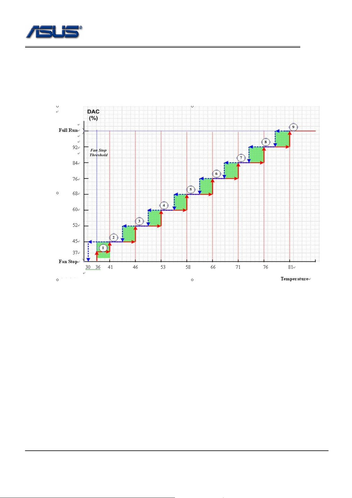
13. Thermal Management
13.1 Thermal Policy
13.2 Thermal Protect Function
For prevent the platform overheated, the bios will make the system into S4 automatically.
While the below status are true, the system will into S4.
(1) The Lid is close.
(2) The temperature is over 100’C.
(3) Both (1) and (2) keep 10 minutes.
6-18

Software Specification
14. Hotkeys & Instant Keys
BIOS should support the following Hotkeys and Instant keys functions.
Table 14-1 Hotkeys/Instant Keys Table
Hotkeys/Instant Keys Function Non ACPI ACPI
Fn+F1
Fn+F2
Fn+F3
Fn+F4
Fn+F5
Fn+F6
Fn+F7
Fn+F8
Fn+F10
Fn+F11
Fn+F12
Power4Gear
Fn+Space
Power4Phone
Fn+T
Splendid
Fn+C
Functions as sleep button No Yes
Bluetooth / Wireless switch on / off
Trigger off email
Trigger off internet
No Yes
No Yes
No Yes
Brightness Up Yes Yes
Brightness Down Yes Yes
LCD backlight ON/OFF Yes Yes
Display Switch Yes Yes
Volume on/off toggling
Adjust Volume
Adjust Volume
No Yes
No Yes
No Yes
Switch the modes of Power4Gear No Yes
Trigger off the Powe r4Phone No Yes
Trigger off the Colo r Enhancement No Yes
Touch Pad
Touch Pad ON/OFF No Yes
Fn+F9
Fn+↑
Fn+↓
Stop No Yes
Play/Pause No Yes
Previous section
Fn+←
No Yes
Previous Track
Next section
Fn+→
No Yes
Next Track
6-19

Software Specification
15. Wireless LAN Control
Wireless On/Off is controlled by Wireless control button.
A7Sv supports Wireless console to control Wireless LAN and Bluetooth.
There are four checked boxes in the Wireless console.
If you select Wireless LAN, it means that only Wireless LAN is controlled by Wireless control button.
If you select Bluetooth, it means that only Bluetooth is controlled by Wireless control button.
If you select both, it means that Wireless LAN and Bluetooth are all controlled by Wireless control button.
When switch the button to left, the Wireless (Wireless LAN or Bluetooth or both) is On.
When switch the button to right, the Wireless (Wireless LAN or Bluetooth or both) is Off.
Under DOS mode, there is no effect on Wireless control when switching the button.
In the bios setup menu, if selecting the following items, the switch button is invalidated.
Security – I/O Interface Security – Wireless Network Interface – [LOCKED]
Security – I/O Interface Security – USB Interface – [LOCKED]
If one of them is [UNLOCKED], the switch button is valid.
6-20

Software Specification
16. BIOS NV Data Auto Save / Restore
Refer to the ASUS BIOS NV Data Auto SaveRestore Requirement verification_v1r00.doc.
6-21
 Loading...