

Page 1

A7S8X-MX
Motherboard
Page 2

E1766E1766
E1766
E1766E1766
First Edition V1First Edition V1
First Edition V1
First Edition V1First Edition V1
September 2004September 2004
September 2004
September 2004September 2004
Copyright © 2004 ASUSTeK COMPUTER INC. All Rights Reserved.
No part of this manual, including the products and software described in it, may be reproduced,
transmitted, transcribed, stored in a retrieval system, or translated into any language in any form
or by any means, except documentation kept by the purchaser for backup purposes, without the
express written permission of ASUSTeK COMPUTER INC. (“ASUS”).
Product warranty or service will not be extended if: (1) the product is repaired, modified or
altered, unless such repair, modification of alteration is authorized in writing by ASUS; or (2)
the serial number of the product is defaced or missing.
ASUS PROVIDES THIS MANUAL “AS IS” WITHOUT WARRANTY OF ANY KIND, EITHER
EXPRESS OR IMPLIED, INCLUDING BUT NOT LIMITED TO THE IMPLIED WARRANTIES
OR CONDITIONS OF MERCHANTABILITY OR FITNESS FOR A PARTICULAR PURPOSE.
IN NO EVENT SHALL ASUS, ITS DIRECTORS, OFFICERS, EMPLOYEES OR AGENTS BE
LIABLE FOR ANY INDIRECT, SPECIAL, INCIDENTAL, OR CONSEQUENTIAL DAMAGES
(INCLUDING DAMAGES FOR LOSS OF PROFITS, LOSS OF BUSINESS, LOSS OF USE
OR DATA, INTERRUPTION OF BUSINESS AND THE LIKE), EVEN IF ASUS HAS BEEN
ADVISED OF THE POSSIBILITY OF SUCH DAMAGES ARISING FROM ANY DEFECT OR
ERROR IN THIS MANUAL OR PRODUCT.
SPECIFICATIONS AND INFORMATION CONTAINED IN THIS MANUAL ARE FURNISHED
FOR INFORMATIONAL USE ONLY, AND ARE SUBJECT TO CHANGE AT ANY TIME
WITHOUT NOTICE, AND SHOULD NOT BE CONSTRUED AS A COMMITMENT BY ASUS.
ASUS ASSUMES NO RESPONSIBILITY OR LIABILITY FOR ANY ERRORS OR
INACCURACIES THAT MAY APPEAR IN THIS MANUAL, INCLUDING THE PRODUCTS
AND SOFTWARE DESCRIBED IN IT.
Products and corporate names appearing in this manual may or may not be registered
trademarks or copyrights of their respective companies, and are used only for identification or
explanation and to the owners’ benefit, without intent to infringe.
iiii
ii
iiii
Page 3

Contents
Notices ................................................................................................ vi
Safety information ............................................................................. vii
About this guide ............................................................................... viii
Typography ......................................................................................... ix
A7S8X-MX specifications summary ...................................................... x
Chapter 1: Product introductionChapter 1: Product introduction
Chapter 1: Product introduction
Chapter 1: Product introductionChapter 1: Product introduction
1.1 Welcome! .............................................................................. 1-2
1.2 Package contents ................................................................. 1-2
1.3 Special features .................................................................... 1-3
1.3.1 Product highlights................................................... 1-3
1.3.2 Innovative ASUS features ....................................... 1-4
1.4 Before you proceed .............................................................. 1-5
1.5 Motherboard overview .......................................................... 1-6
1.5.1 Placement direction ................................................ 1-6
1.5.2 Screw holes ............................................................ 1-6
1.5.3 Motherboard layout ................................................ 1-7
1.6 Central Processing Unit (CPU) .............................................. 1-8
1.7 System memory ................................................................. 1-10
1.7.1 Overview ............................................................... 1-10
1.7.2 Memory Configurations .........................................1-10
1.7.3 Installing a DIMM ................................................... 1-12
1.7.4 Removing a DIMM ................................................. 1-12
1.8 Expansion slots ................................................................... 1-13
1.8.1 Installing an expansion card .................................. 1-13
1.8.2 Configuring an expansion card.............................. 1-13
1.8.3 Interrupt assignments .......................................... 1-14
1.8.4 PCI slots ................................................................ 1-15
1.8.5 AGP slot ................................................................ 1-15
1.9 Jumpers .............................................................................. 1-16
1.10 Connectors ......................................................................... 1-19
1.10.1 Rear panel connectors .......................................... 1-19
1.10.2 Internal connectors............................................... 1-21
iiiiii
iii
iiiiii
Page 4

Contents
Chapter 2: BIOS setupChapter 2: BIOS setup
Chapter 2: BIOS setup
Chapter 2: BIOS setupChapter 2: BIOS setup
2.1 Managing and updating your BIOS ........................................ 2-2
2.1.1 Creating a bootable floppy disk .............................. 2-2
2.1.2 AwardBIOS Flash Utility .......................................... 2-3
2.1.3 ASUS EZ Flash utility .............................................. 2-5
2.1.4 ASUS CrashFree BIOS utility ................................... 2-6
2.1.5 ASUS Update utility ................................................ 2-7
2.2 BIOS Setup program ........................................................... 2-10
2.2.1 BIOS menu bar ...................................................... 2-11
2.2.2 Legend bar ........................................................... 2-11
2.3 Main Menu........................................................................... 2-13
2.3.1 System Time ......................................................... 2-13
2.3.2 System Date ......................................................... 2-13
2.3.3 Legacy Diskette A ................................................ 2-13
2.3.4 HDD SMART Monitoring ........................................ 2-13
2.3.5 Installed Memory .................................................. 2-13
2.3.6 Primary and Secondary IDE Master/Slave ............. 2-14
2.3.7 First and Second SATA Master ............................. 2-15
2.4 Advanced Menu .................................................................. 2-16
2.4.1 CPU configuration ................................................. 2-17
2.4.2 Chipset configuration ........................................... 2-18
2.4.3 PCIPnP ................................................................... 2-21
2.4.4 Onboard device configuration ............................. 2-22
2.4.5 USB configuration ................................................ 2-24
2.5 Power Menu ........................................................................ 2-25
2.5.1 APM configuration ................................................ 2-26
2.5.2 Hardware monitor ................................................. 2-29
2.6 Boot Menu .......................................................................... 2-30
2.6.1 Boot Device Priority .............................................. 2-30
2.6.2 Removable drives ................................................. 2-31
iviv
iv
iviv
2.6.3 Hard Disk Drives ................................................... 2-31
2.6.4 CD-ROM drives ...................................................... 2-32
2.6.5 Boot settings configuration .................................. 2-32
2.6.6 Security ................................................................ 2-34
2.7 Exit menu ........................................................................... 2-35
Page 5

Contents
Chapter 3: Software supportChapter 3: Software support
Chapter 3: Software support
Chapter 3: Software supportChapter 3: Software support
3.1 Installing an operating system ............................................. 3-2
3.2 Support CD information ........................................................ 3-2
3.2.1 Running the support CD ......................................... 3-2
3.2.2 Drivers menu .......................................................... 3-3
3.2.3 Utilities menu .......................................................... 3-4
3.2.4 ASUS Contact information ...................................... 3-5
vv
v
vv
Page 6
Notices
Federal Communications Commission StatementFederal Communications Commission Statement
Federal Communications Commission Statement
Federal Communications Commission StatementFederal Communications Commission Statement
This device complies with Part 15 of the FCC Rules. Operation is subject to
the following two conditions:
•
This device may not cause harmful interference, and
•
This device must accept any interference received including interference
that may cause undesired operation.
This equipment has been tested and found to comply with the limits for a
Class B digital device, pursuant to Part 15 of the FCC Rules. These limits are
designed to provide reasonable protection against harmful interference in a
residential installation. This equipment generates, uses and can radiate radio
frequency energy and, if not installed and used in accordance with
manufacturer’s instructions, may cause harmful interference to radio
communications. However, there is no guarantee that interference will not
occur in a particular installation. If this equipment does cause harmful
interference to radio or television reception, which can be determined by
turning the equipment off and on, the user is encouraged to try to correct
the interference by one or more of the following measures:
•
Reorient or relocate the receiving antenna.
•
Increase the separation between the equipment and receiver.
•
Connect the equipment to an outlet on a circuit different from that to
which the receiver is connected.
•
Consult the dealer or an experienced radio/TV technician for help.
The use of shielded cables for connection of the monitor to the graphics
card is required to assure compliance with FCC regulations. Changes or
modifications to this unit not expressly approved by the party
responsible for compliance could void the user’s authority to operate
this equipment.
Canadian Department of Communications StatementCanadian Department of Communications Statement
Canadian Department of Communications Statement
Canadian Department of Communications StatementCanadian Department of Communications Statement
This digital apparatus does not exceed the Class B limits for radio noise
emissions from digital apparatus set out in the Radio Interference
Regulations of the Canadian Department of Communications.
This class B digital apparatus complies with CanadianThis class B digital apparatus complies with Canadian
This class B digital apparatus complies with Canadian
This class B digital apparatus complies with CanadianThis class B digital apparatus complies with Canadian
ICES-003.ICES-003.
ICES-003.
ICES-003.ICES-003.
vivi
vi
vivi
Page 7

Safety information
Electrical safetyElectrical safety
Electrical safety
Electrical safetyElectrical safety
•
To prevent electrical shock hazard, disconnect the power cable from
the electrical outlet before relocating the system.
•
When adding or removing devices to or from the system, ensure that
the power cables for the devices are unplugged before the signal cables
are connected. If possible, disconnect all power cables from the existing
system before you add a device.
•
Before connecting or removing signal cables from the motherboard,
ensure that all power cables are unplugged.
•
Seek professional assistance before using an adapter or extension cord.
These devices could interrupt the grounding circuit.
•
Make sure that your power supply is set to the correct voltage in your
area. If you are not sure about the voltage of the electrical outlet you
are using, contact your local power company.
•
If the power supply is broken, do not try to fix it by yourself. Contact a
qualified service technician or your retailer.
Operation safetyOperation safety
Operation safety
Operation safetyOperation safety
•
Before installing the motherboard and adding devices on it, carefully read
all the manuals that came with the package.
•
Before using the product, make sure all cables are correctly connected
and the power cables are not damaged. If you detect any damage,
contact your dealer immediately.
•
To avoid short circuits, keep paper clips, screws, and staples away from
connectors, slots, sockets and circuitry.
•
Avoid dust, humidity, and temperature extremes. Do not place the
product in any area where it may become wet.
•
Place the product on a stable surface.
•
If you encounter technical problems with the product, contact a qualified
service technician or your retailer.
viivii
vii
viivii
Page 8

About this guide
This user guide contains the information you need when installing and
configuring the motherboard.
How this guide is organizedHow this guide is organized
How this guide is organized
How this guide is organizedHow this guide is organized
This manual contains the following parts:
••
Chapter 1: Product introductionChapter 1: Product introduction
•
Chapter 1: Product introduction
••
Chapter 1: Product introductionChapter 1: Product introduction
This chapter describes the features of the motherboard and the new
technology it supports. This chapter also lists the hardware setup
procedures that you have to perform when installing system
components. It includes description of the jumpers and connectors on
the motherboard.
••
Chapter 2: BIOS setupChapter 2: BIOS setup
•
Chapter 2: BIOS setup
••
Chapter 2: BIOS setupChapter 2: BIOS setup
This chapter tells how to change system settings through the BIOS
Setup menus. Detailed descriptions of the BIOS parameters are also
provided.
••
Chapter 3: Software supportChapter 3: Software support
•
Chapter 3: Software support
••
Chapter 3: Software supportChapter 3: Software support
This chapter describes the contents of the support CD that comes
with the motherboard package.
Where to find more informationWhere to find more information
Where to find more information
Where to find more informationWhere to find more information
Refer to the following sources for additional information and for product
and software updates.
1.1.
ASUS websitesASUS websites
1.
ASUS websites
1.1.
ASUS websitesASUS websites
The ASUS website provides updated information on ASUS hardware
and software products. Refer to the ASUS contact information.
2.2.
Optional documentationOptional documentation
2.
Optional documentation
2.2.
Optional documentationOptional documentation
Your product package may include optional documentation, such as
warranty flyers, that may have been added by your dealer. These
documents are not part of the standard package.
viiiviii
viii
viiiviii
Page 9

Conventions used in this guideConventions used in this guide
Conventions used in this guide
Conventions used in this guideConventions used in this guide
To make sure that you perform certain tasks properly, take note of the
following symbols used throughout this manual.
DANGER/WARNING: DANGER/WARNING:
DANGER/WARNING: Information to prevent injury to yourself
DANGER/WARNING: DANGER/WARNING:
when trying to complete a task.
CAUTION:CAUTION:
CAUTION: Information to prevent damage to the components
CAUTION:CAUTION:
when trying to complete a task.
IMPORTANT: IMPORTANT:
IMPORTANT: Instructions that you MUST follow to complete a
IMPORTANT: IMPORTANT:
task.
NOTE: NOTE:
NOTE: Tips and additional information to help you complete a
NOTE: NOTE:
task.
Typography
Bold textBold text
Bold text Indicates a menu or an item to select
Bold textBold text
Italics
<Key> Keys enclosed in the less-than and greater-than
<Key1+Key2+Key3> If you must press two or more keys
CommandCommand
Command Means that you must type the command exactly as
CommandCommand
Used to emphasize a word or a phrase
sign means that you must press the enclosed key
Example: <Enter> means that you must press the
Enter or Return key
simultaneously, the key names are linked with a
plus sign (+)
Example: <Ctrl+Alt+D>
shown
Example: At the DOS prompt, type the command
line:
D:\bootdisk\makeboot a:D:\bootdisk\makeboot a:
D:\bootdisk\makeboot a:
D:\bootdisk\makeboot a:D:\bootdisk\makeboot a:
ixix
ix
ixix
Page 10

A7S8X-MX specifications summary
CPUCPU
CPU
CPUCPU
ChipsetChipset
Chipset
ChipsetChipset
Front Side BusFront Side Bus
Front Side Bus
Front Side BusFront Side Bus
MemoryMemory
Memory
MemoryMemory
Expansion slotsExpansion slots
Expansion slots
Expansion slotsExpansion slots
StorageStorage
Storage
StorageStorage
AudioAudio
Audio
AudioAudio
LANLAN
LAN
LANLAN
Socket A for AMD Athlon™ XP/Sempron™ processors
Northbridge: SiS 741GX
Southbridge: SiS 964 (without RAID support)
333/266/200 MHz
2 x 184-pin DIMM sockets support unbufferred non-ECC
333/266/200 MHz DDR SDRAM memory modules
1 x AGP slot for 1.5V AGP cards
2 x PCI slots
SiS 964 Southbridge supports:
- 4 x Ultra DMA 133/100/66 hard disk drives
- 2 x Serial ATA hard disk drives (supported only
under Windows® XP/2000/2003
ADI AD1888 SoundMax
S/PDIF out interface support
Realtek® RTL 8201CL 10/100 Mbps LAN PHY
®
6-channel CODEC
USBUSB
USB
USBUSB
Special featuresSpecial features
Special features
Special featuresSpecial features
BIOS featuresBIOS features
BIOS features
BIOS featuresBIOS features
Rear panelRear panel
Rear panel
Rear panelRear panel
Supports up to 8 USB 2.0 ports
ASUS EZ Flash
ASUS CrashFree BIOS
ASUS C.O.P. (CPU Overheating Protection)
ASUS MyLogo™
2 Mb Flash EEPROM, Phoenix-Award BIOS with enhanced
ACPI, DMI, Green, and PnP features
1 x PS/2 mouse port
1 x Parallel port
1 x LAN (RJ-45) port
4 x USB 2.0 ports
1 x VGA port
1 x Coaxial S/PDIF out port
1 x PS/2 keyboard port
6-channel audio ports
(continued on the next page)
xx
x
xx
Page 11

A7S8X-MX specifications summary
InternalInternal
Internal
InternalInternal
connectorsconnectors
connectors
connectorsconnectors
InduIndu
stry standarstry standar
Indu
stry standar
InduIndu
stry standarstry standar
1 x Floppy disk drive connector
1 x Primary IDE connector
1 x Secondary IDE connector
2 x Serial ATA connectors
1 x CPU fan connector
1 x Chassis fan connector
2 x USB 2.0 connectors for 4 additional USB 2.0 ports
1 x GAME/MIDI connector
1 x 20-pin ATX power connector
1 x CD in connector
1 x AUX connector
1 x Front panel audio connector
1 x COM port connector
1 x Speaker out connector
1 x Power LED connector
1 x System panel connector
dd
d
PCI 2.2, USB 2.0
dd
Support CDSupport CD
Support CD
Support CDSupport CD
contentscontents
contents
contentscontents
Form FactorForm Factor
Form Factor
Form FactorForm Factor
Device drivers
ASUS PC Probe
ASUS Update
Anti-virus software (OEM version)
Micro ATX form factor: 9.6 in x 7.8 in (24.4 cm x 19.8 cm)
*Specifications are subject to change without notice.
xixi
xi
xixi
Page 12

xiixii
xii
xiixii
Page 13

This chapter describes the motherboard
features and the new technologies
it supports.
introduction
Product
1
ASUS A7S8X-MXASUS A7S8X-MX
ASUS A7S8X-MX
ASUS A7S8X-MXASUS A7S8X-MX
1-11-1
1-1
1-11-1
Page 14

1.1 Welcome!
®®
®
Thank you for buying an ASUSThank you for buying an ASUS
Thank you for buying an ASUS
Thank you for buying an ASUSThank you for buying an ASUS
®®
A7S8X-MX motherboard! A7S8X-MX motherboard!
A7S8X-MX motherboard!
A7S8X-MX motherboard! A7S8X-MX motherboard!
The motherboard delivers a host of new features and latest technologies,
making it another standout in the long line of ASUS quality motherboards!
Before you start installing the motherboard and hardware devices on it,
check the items in your package with the list below.
1.2 Package contents
Check your motherboard package for the following items.
MotherboardMotherboard
Motherboard ASUS A7S8X-MX motherboard
MotherboardMotherboard
CablesCables
Cables 1 x Serial port (COM) cable
CablesCables
1 x Ultra DMA cable
1 x Floppy disk drive cable
AccessoryAccessory
Accessory I/O shield
AccessoryAccessory
Application CDApplication CD
Application CD ASUS motherboard support CD
Application CDApplication CD
DocumentationDocumentation
Documentation User guide
DocumentationDocumentation
If any of the above items is damaged or missing, contact your retailer.
1-21-2
1-2
1-21-2
Chapter 1: Product introductionChapter 1: Product introduction
Chapter 1: Product introduction
Chapter 1: Product introductionChapter 1: Product introduction
Page 15

1.3 Special features
1.3.11.3.1
1.3.1
1.3.11.3.1
AMD Athon™ XP/Sempron™ processor support AMD Athon™ XP/Sempron™ processor support
AMD Athon™ XP/Sempron™ processor support
AMD Athon™ XP/Sempron™ processor support AMD Athon™ XP/Sempron™ processor support
The motherboard comes with a 462-pin surface mount, Zero Insertion
Force (ZIF) socket that supports 333 MHz front side bus frequency for
AMD Athlon™ XP/Sempron™ processors. With an integrated low-latency
high-bandwidth memory controller, the motherboard allows increased office
productivity and enhanced digital media experience. See page 1-8.
AGP 8X support AGP 8X support
AGP 8X support
AGP 8X support AGP 8X support
The AGP 8X (AGP 3.0) VGA interface specification enables enhanced
graphics performance with high bandwidth speeds up to 2.12 GB/s. See
page 1-15.
Powerful integrated graphics Powerful integrated graphics
Powerful integrated graphics
Powerful integrated graphics Powerful integrated graphics
The SiS 741GX IGUI Host Memory Controller (HMC) features the SiS
Real256E, an integrated graphics engine for enhanced 3D, 2D, and video
capabilities.
Product highlightsProduct highlights
Product highlights
Product highlightsProduct highlights
Serial ATA technology Serial ATA technology
Serial ATA technology
Serial ATA technology Serial ATA technology
The motherboard supports the Serial ATA technology through the Serial ATA
interfaces and the SiS 964. The SATA specification allows for thinner, more
flexible cables with lower pin count, reduced voltage requirement, and up to
150 MB/s data transfer rate. See page 1-23.
6-channel digital audio 6-channel digital audio
6-channel digital audio
6-channel digital audio 6-channel digital audio
Providing high-quality, 6-channel audio solution is the onboard ADI AD1888
AC`97 audio CODEC. This motherboard comes with a coaxial S/PDIF
connector on the rear panel to turn your computer into a high-end
entertainment system with digital connectivity to powerful sound systems.
See page 1-19.
Integrated 10/100 LAN controller Integrated 10/100 LAN controller
Integrated 10/100 LAN controller
Integrated 10/100 LAN controller Integrated 10/100 LAN controller
The onboard Realtek RTL8201CL is an integrated single-chip Fast Ethernet
LAN controller with enhanced ACPI management function to provide
efficient power management for advanced operating systems. See page
1-19.
ASUS A7S8X-MXASUS A7S8X-MX
ASUS A7S8X-MX
ASUS A7S8X-MXASUS A7S8X-MX
1-31-3
1-3
1-31-3
Page 16

S/PDIF digital sound ready S/PDIF digital sound ready
S/PDIF digital sound ready
S/PDIF digital sound ready S/PDIF digital sound ready
The motherboard supports the S/PDIF In/Out function through the S/PDIF
interfaces on the rear panel and at midboard. The S/PDIF technology turns
your computer into a high-end entertainment system with digital connectivity
to powerful audio and speaker systems. See page 1-20.
USB 2.0 technology USB 2.0 technology
USB 2.0 technology
USB 2.0 technology USB 2.0 technology
The motherboard implements the Universal Serial Bus (USB) 2.0
specification, dramatically increasing the connection speed from the
12 Mbps bandwidth on USB 1.1 to a fast 480 Mbps on USB 2.0. USB 2.0 is
backward compatible with USB 1.1. See pages 1-20 and 1-25.
1.3.21.3.2
1.3.2
1.3.21.3.2
C.O.P. (CPU Overheating ProtectionC.O.P. (CPU Overheating Protection
C.O.P. (CPU Overheating Protection)
C.O.P. (CPU Overheating ProtectionC.O.P. (CPU Overheating Protection
With AMD® Athlon XP™ installed, the motherboard offers automatic CPU
Overheating Protection to prolong the life of the entire system. If the CPU
temperature exceeds the set criteria, the PC shuts down automatically.
ASUS EZ Flash BIOS ASUS EZ Flash BIOS
ASUS EZ Flash BIOS
ASUS EZ Flash BIOS ASUS EZ Flash BIOS
With the ASUS EZ Flash, you can easily update the system BIOS even
before loading the operating system. No need to use a DOS-based utility or
boot from a floppy disk. See page 2-5.
ASUS CrashFree BIOS ASUS CrashFree BIOS
ASUS CrashFree BIOS
ASUS CrashFree BIOS ASUS CrashFree BIOS
This feature allows you to restore the original BIOS data from a floppy disk
when the BIOS codes and data are corrupted. This protection eliminates the
need to buy a replacement ROM chip. See page 2-6 for details.
Innovative ASUS featuresInnovative ASUS features
Innovative ASUS features
Innovative ASUS featuresInnovative ASUS features
ASUS MyLogo™ ASUS MyLogo™
ASUS MyLogo™
ASUS MyLogo™ ASUS MyLogo™
This new feature present in the motherboard allows you to personalize and
add style to your system with customizable boot logos. See page 2-33.
1-41-4
1-4
1-41-4
Chapter 1: Product introductionChapter 1: Product introduction
Chapter 1: Product introduction
Chapter 1: Product introductionChapter 1: Product introduction
Page 17
1.4 Before you proceed
Take note of the following precautions before you install motherboard
components or change any motherboard settings.
• Unplug the power cord from the wall socket before touching any
component.
• Use a grounded wrist strap or touch a safely grounded object or to a
metal object, such as the power supply case, before handling
components to avoid damaging them due to static electricity
• Hold components by the edges to avoid touching the ICs on them.
• Whenever you uninstall any component, place it on a grounded
antistatic pad or in the bag that came with the component.
Before you install or remove any component, ensureBefore you install or remove any component, ensure
•
Before you install or remove any component, ensure
Before you install or remove any component, ensureBefore you install or remove any component, ensure
that the ATX power supply is switched off or thethat the ATX power supply is switched off or the
that the ATX power supply is switched off or the
that the ATX power supply is switched off or thethat the ATX power supply is switched off or the
power cord is detached from the power supply. power cord is detached from the power supply.
power cord is detached from the power supply. Failure
power cord is detached from the power supply. power cord is detached from the power supply.
to do so may cause severe damage to the motherboard, peripherals,
and/or components.
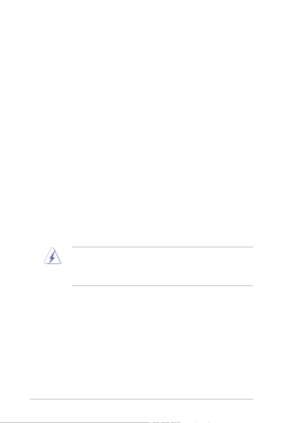
Onboard LEDOnboard LED
Onboard LED
Onboard LEDOnboard LED
The motherboard comes with a standby power LED that lights up to
indicate that the system is ON, in sleep mode, or in soft-off mode.
This is a reminder that you should shut down the system and unplug
the power cable before removing or plugging in any motherboard
component. The illustration below shows the location of the onboard
LED.
A7S8X-MX
SB_PWR1
®
A7S8X-MX Onboard LED
ON
Standby
Power
OFF
Powered
Off
ASUS A7S8X-MXASUS A7S8X-MX
ASUS A7S8X-MX
ASUS A7S8X-MXASUS A7S8X-MX
1-51-5
1-5
1-51-5
Page 18
1.5 Motherboard overview
Before you install the motherboard, study the configuration of your chassis
to ensure that the motherboard fits into it.
Make sure to unplug the power cord before installing or removing the
motherboard. Failure to do so can cause you physical injury and damage
motherboard components.
1.5.11.5.1
1.5.1
1.5.11.5.1
Placement directionPlacement direction
Placement direction
Placement directionPlacement direction
When installing the motherboard, make sure that you place it into the
chassis in the correct orientation. The edge with external ports goes to the
rear part of the chassis as indicated in the image below.
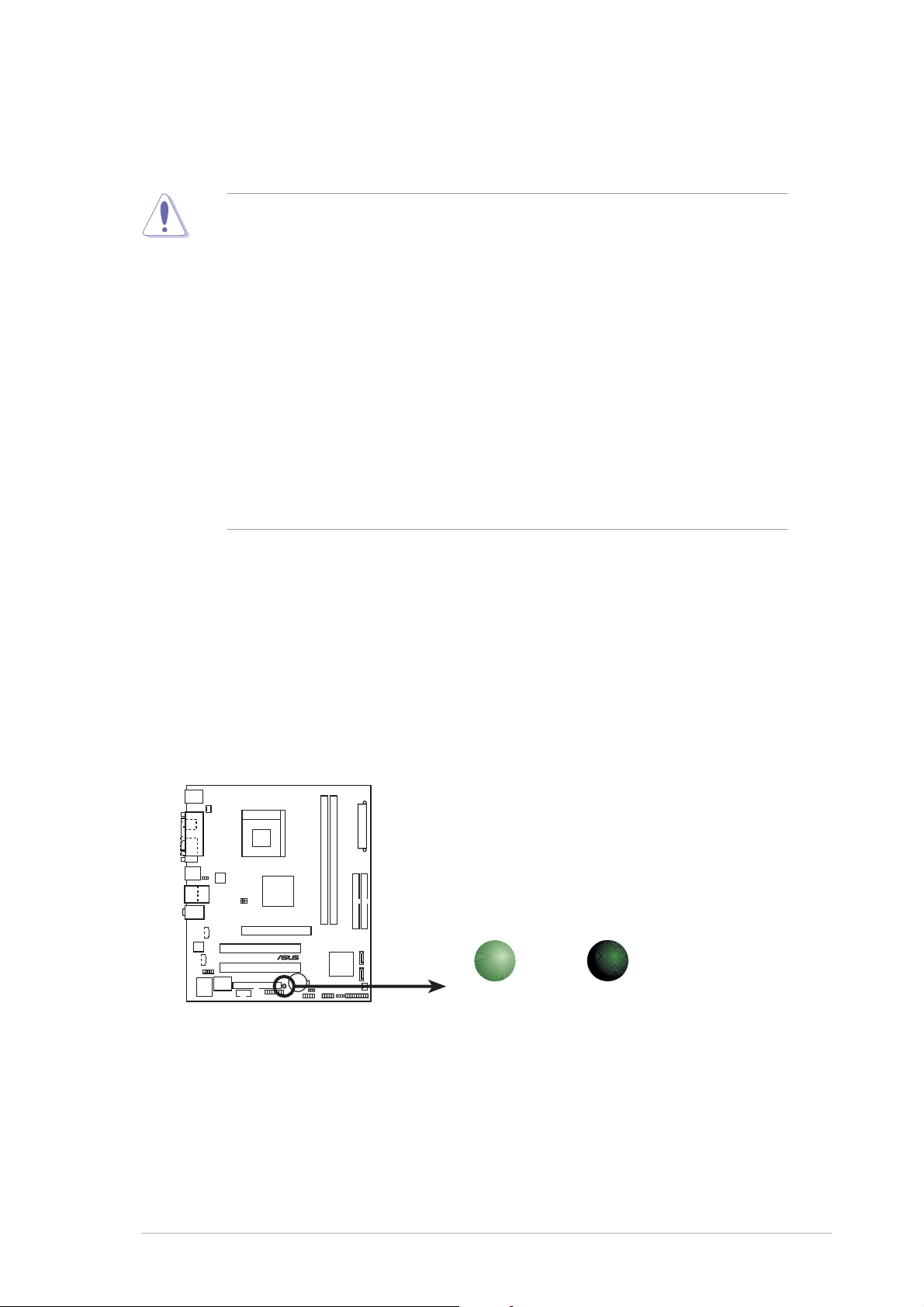
1.5.21.5.2
1.5.2
1.5.21.5.2
Screw holesScrew holes
Screw holes
Screw holesScrew holes
Place six (6) screws into the holes indicated by circles to secure the
motherboard to the chassis.
Do not overtighten the screws! Doing so can damage the motherboard.
Place this side towardsPlace this side towards
Place this side towards
Place this side towardsPlace this side towards
the rear of the chassisthe rear of the chassis
the rear of the chassis
the rear of the chassisthe rear of the chassis
1-61-6
1-6
1-61-6
A7S8X-MX
®
Chapter 1: Product introductionChapter 1: Product introduction
Chapter 1: Product introduction
Chapter 1: Product introductionChapter 1: Product introduction
Page 19
1.5.31.5.3
1.5.3
1.5.31.5.3
PS/2KBMS
T: Mouse
B: Keyboard
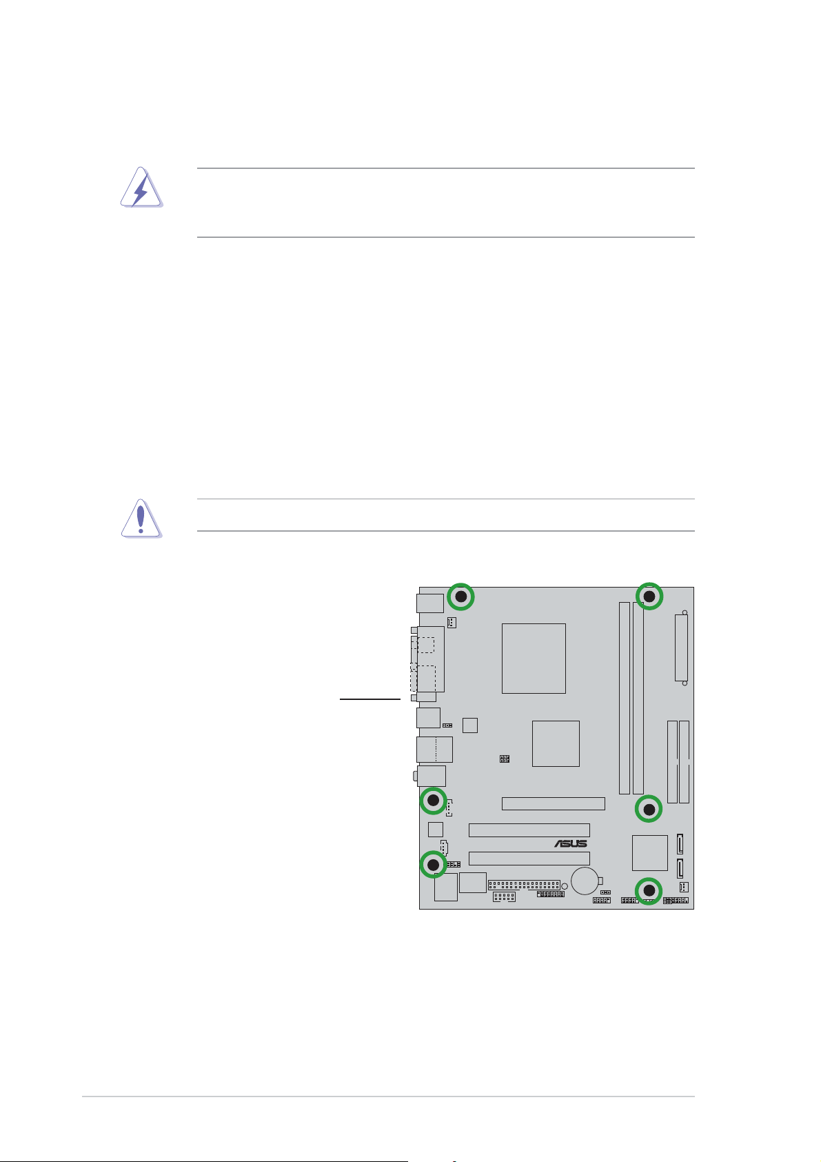
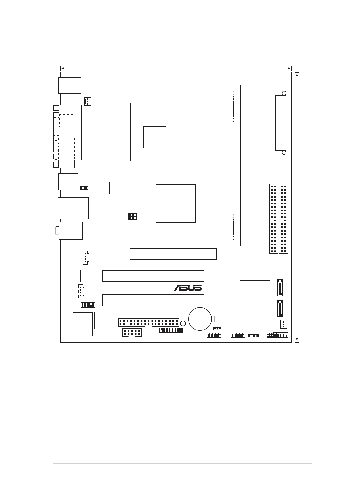
Motherboard layoutMotherboard layout
Motherboard layout
Motherboard layoutMotherboard layout
19.8cm (7.8in)
SPDIF_O
VGA1
T:USB4
B:USB3
USB2.0
T: USB1
B: USB2
Top:Line In
Center:Line Out
Below:Mic In
PARALLEL PORT
Top:
RJ-45
CD1
CPU_FAN1
USBPW1234
REL8201CL
FSB_SEL1
FSB_SEL0
Socket 462
SIS
741GX
AGP1
DDR DIMM1 (64/72 bit, 184-pin module)
A7S8X-MX
ATXPWR
DDR DIMM2 (64/72 bit, 184-pin module)
24.4cm (9.6in)
PRI_IDE
SEC_IDE
AD1888
AUX1
FP_AUDIO1
I/O
Super
2Mbit
ISA
COM1
PCI1
PCI2
FLOPPY1
GAME1
®
CR2032 3V
Lithium Cell
CMOS Power
USB56
SB_PWR1
USBPW5678
USB78
SIS
964
SPEAKER1
CHA_FAN1
PWRLED1
CLRTC1
SATA 1 SATA 2
PANEL1
ASUS A7S8X-MXASUS A7S8X-MX
ASUS A7S8X-MX
ASUS A7S8X-MXASUS A7S8X-MX
1-71-7
1-7
1-71-7
Page 20
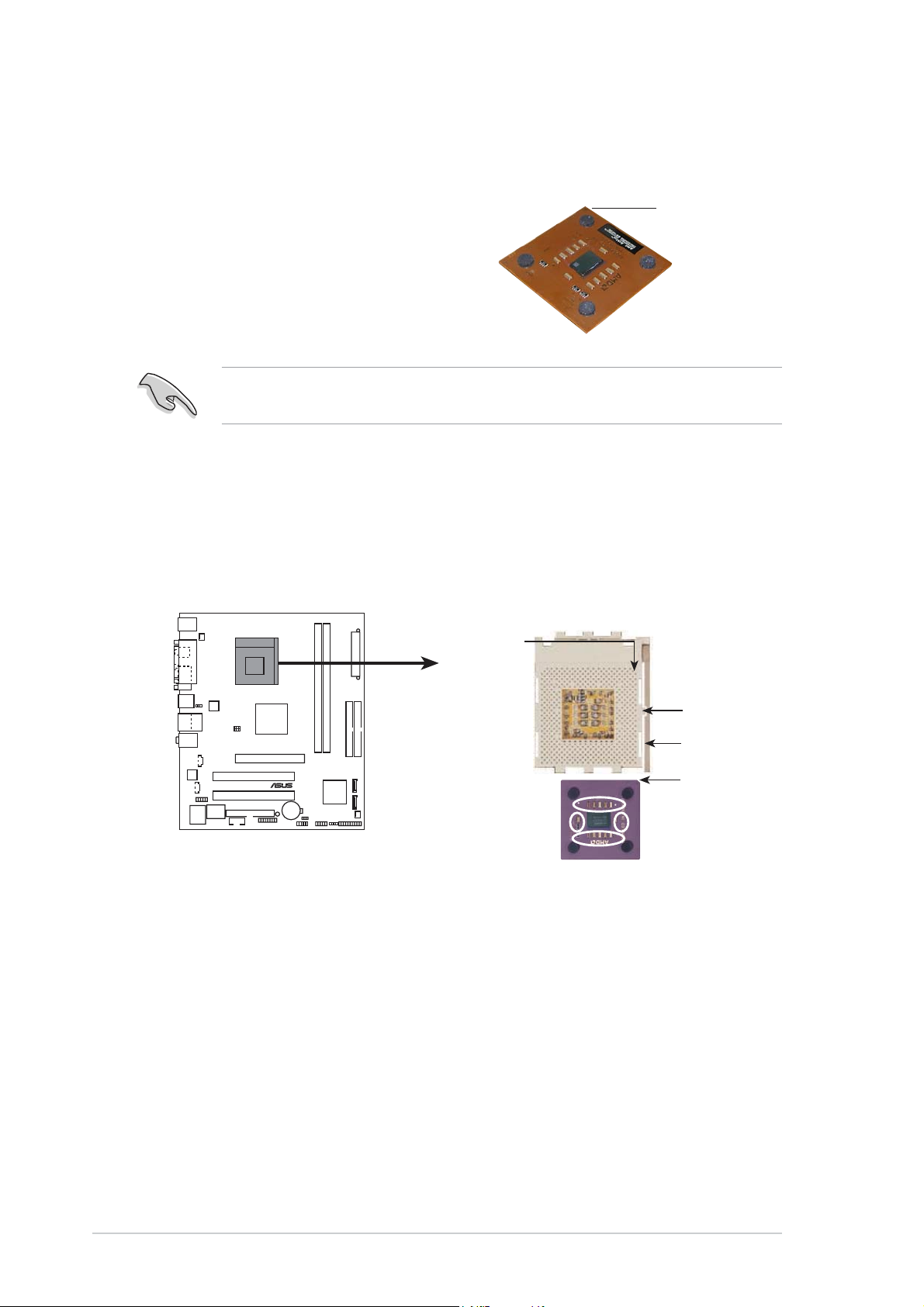
1.6 Central Processing Unit (CPU)
The motherboard comes with a surface mount 462-pin Zero Insertion Force
(ZIF) socket designed for the AMD Athlon™ XP/Sempron™ processor.
Take note of the marked corner (with
gold triangle) on the CPU. This mark
should match a specific corner on the
socket to ensure correct installation.
Do not use processors with core speeds of less than 1 GHz on this
motherboard.
Installing the CPUInstalling the CPU
Installing the CPU
Installing the CPUInstalling the CPU
Follow these steps to install a CPU.
1. Locate the 462-pin ZIF socket on the motherboard.
CPU NOTCH
TO INNER
CORNER
GoldGold
Gold
GoldGold
triangletriangle
triangle
triangletriangle
A7S8X-MX
®
A7S8X-MX CPU Socket 462
AMD™ CPU
LOCK
LEVER
CPU NOTCH
1-81-8
1-8
1-81-8
Chapter 1: Product introductionChapter 1: Product introduction
Chapter 1: Product introduction
Chapter 1: Product introductionChapter 1: Product introduction
Page 21
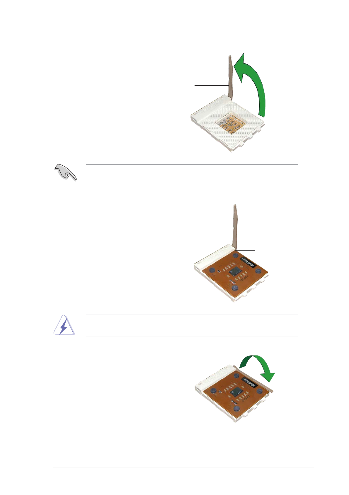
2. Unlock the socket by pressing
the lever sideways, then lift it up
to a 90°-100° angle.
SocketSocket
Socket
SocketSocket
leverlever
lever
leverlever
Make sure that the socket lever is lifted up to 90°-100° angle; otherwise
the CPU does not fit in completely.
3. Position the CPU above the
socket such that the CPU corner
with the gold triangle matches
the base of the socket lever.
90°-100°90°-100°
90°-100°
90°-100°90°-100°
angleangle
angle
angleangle
4. Carefully insert the CPU into the
socket until it fits in place.
The CPU fits only in one correct orientation. DO NOT force the CPU into
the socket to prevent bending the pins and damaging the CPU!
5. When the CPU is in place, push
down the socket lever to secure
the CPU. The lever clicks on the
side tab to indicate that it is
locked.
Gold triangleGold triangle
Gold triangle
Gold triangleGold triangle
ASUS A7S8X-MXASUS A7S8X-MX
ASUS A7S8X-MX
ASUS A7S8X-MXASUS A7S8X-MX
1-91-9
1-9
1-91-9
Page 22
1.7 System memory
1.7.11.7.1
1.7.1
1.7.11.7.1
OverviewOverview
Overview
OverviewOverview
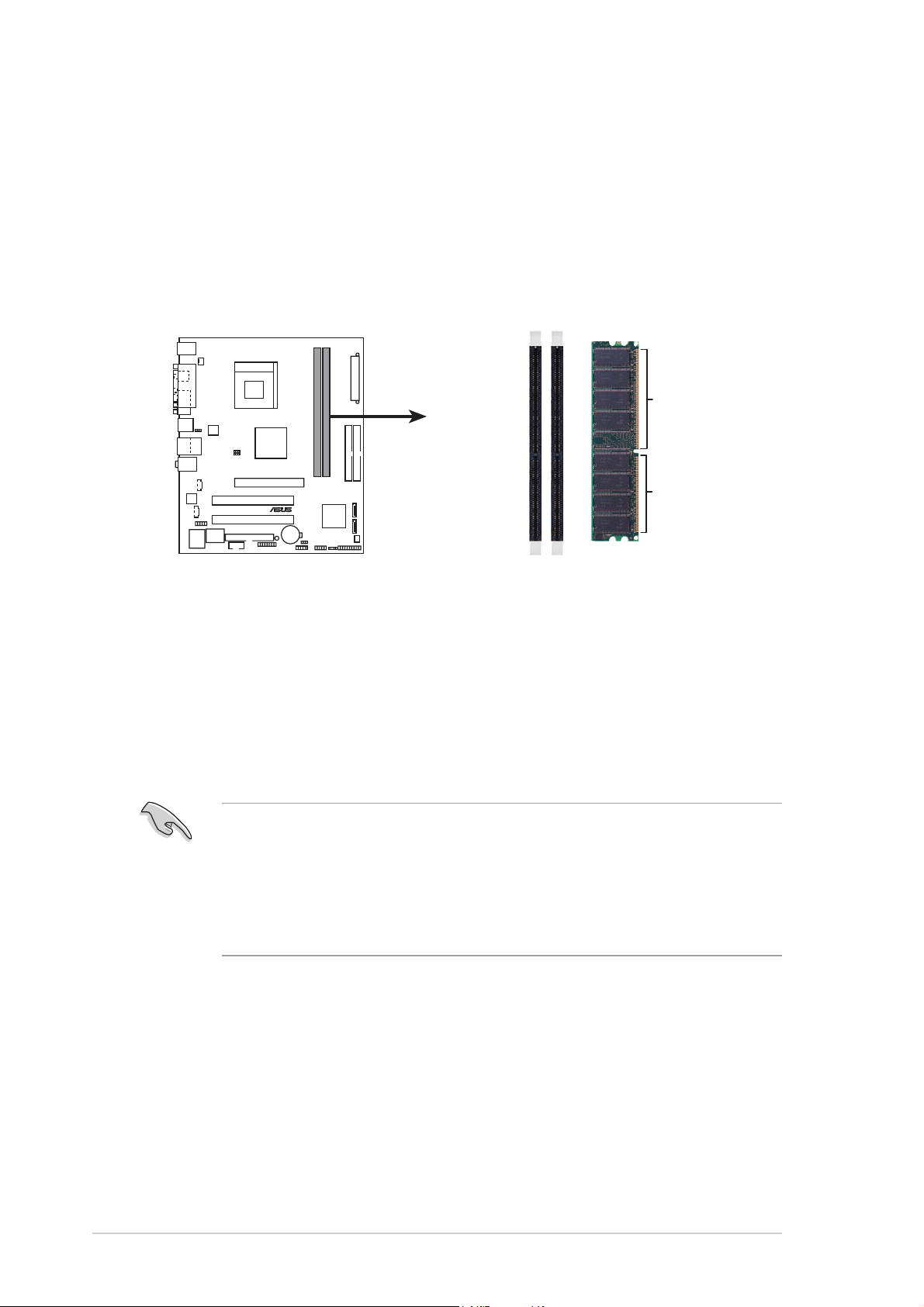
The motherboard comes with two Double Data Rate (DDR) Dual Inline
Memory Module (DIMM) sockets. These sockets support up to 2 GB system
memory using 184-pin PC2700/PC2100 unbuffered DDR DIMMs and allow
up to 2.7 GB/s data transfer rate.
The following figure illustrates the location of the DDR DIMM sockets.
A7S8X-MX
®
A7S8X-MX 184-pin DDR DIMM sockets
DIMM1
DIMM2
80 Pins 104 Pins
1.7.21.7.2
1.7.2
1.7.21.7.2
Memory ConfigurationsMemory Configurations
Memory Configurations
Memory ConfigurationsMemory Configurations
You may install 64 MB, 128 MB, 256 MB, 512 MB and 1 GB unbuffered
non-ECC DDR DIMMs into the DIMM sockets using the memory
configurations in this section.
•
Installing DDR DIMMs other than the recommended configurations
may cause memory sizing error or system boot failure. Use any of
the recommended configurations in the table on the next page.
•
Always install DIMMs with the same CAS latency. For optimum
compatibility, we recommend that you obtain memory modules from
the same vendor.
1-101-10
1-10
1-101-10
Chapter 1: Product introductionChapter 1: Product introduction
Chapter 1: Product introduction
Chapter 1: Product introductionChapter 1: Product introduction
Page 23
Recommended memory configurationsRecommended memory configurations
Recommended memory configurations
Recommended memory configurationsRecommended memory configurations
SocketsSockets
Sockets
SocketsSockets
ModeMode
Mode
ModeMode
DIMM_A1DIMM_A1
DIMM_A1
DIMM_A1DIMM_A1
DIMM_A2DIMM_A2
DIMM_A2
DIMM_A2DIMM_A2
Single-channel (1) Populated —
(2) — Populated
(3) Populated Populated
Memory frequency/CPU FSB synchronizationMemory frequency/CPU FSB synchronization
Memory frequency/CPU FSB synchronization
Memory frequency/CPU FSB synchronizationMemory frequency/CPU FSB synchronization
CPU FSBCPU FSB
CPU FSB
CPU FSBCPU FSB
333 MHz PC2700/PC2100 333/266 MHz
266 MHz PC2100 266 MHz
DDR DIMM TypeDDR DIMM Type
DDR DIMM Type
DDR DIMM TypeDDR DIMM Type
Memory FrequencyMemory Frequency
Memory Frequency
Memory FrequencyMemory Frequency
Obtain DDR DIMMs only from qualified vendors for better system
performance.
ASUS A7S8X-MXASUS A7S8X-MX
ASUS A7S8X-MX
ASUS A7S8X-MXASUS A7S8X-MX
1-111-11
1-11
1-111-11
Page 24
1.7.31.7.3
1.7.3
1.7.31.7.3
Installing a DIMMInstalling a DIMM
Installing a DIMM
Installing a DIMMInstalling a DIMM
Make sure to unplug the power supply before adding or removing DIMMs
or other system components. Failure to do so may cause severe damage
to both the motherboard and the components.
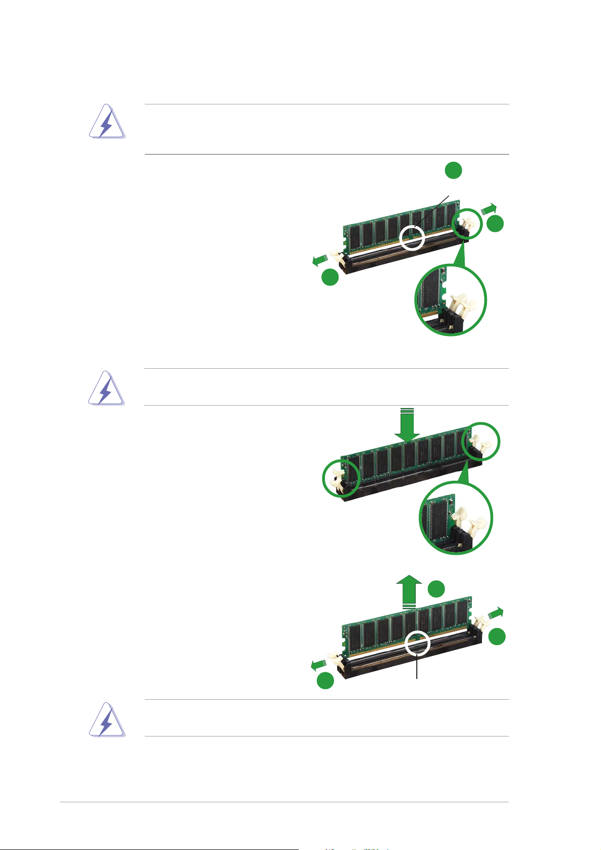
1. Unlock a DIMM socket by
pressing the retaining clips
outward.
2. Align a DIMM on the socket such
that the notch on the DIMM
matches the break on the
socket.
2
DDR DIMM notchDDR DIMM notch
DDR DIMM notch
DDR DIMM notchDDR DIMM notch
1
1
Unlocked retaining clipUnlocked retaining clip
Unlocked retaining clip
Unlocked retaining clipUnlocked retaining clip
A DDR DIMM is keyed with a notch so that it fits in only one direction.
DO NOT force a DIMM into a socket to avoid damaging the DIMM.
3. Firmly insert the DIMM into the
socket until the retaining clips
snap back in place and the DIMM
is properly seated.
Locked retaining clipLocked retaining clip
Locked retaining clip
Locked retaining clipLocked retaining clip
1.7.41.7.4
1.7.4
1.7.41.7.4
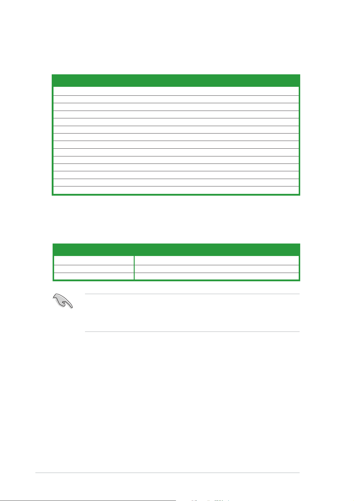
Removing a DIMMRemoving a DIMM
Removing a DIMM
Removing a DIMMRemoving a DIMM
Follow these steps to remove a DIMM.
1. Simultaneously press the
retaining clips outward to unlock
the DIMM.
2
1
Support the DIMM lightly with your fingers when pressing the retaining
clips. The DIMM might get damaged when it flips out with extra force.
2. Remove the DIMM from the socket.
1-121-12
1-12
1-121-12
1
Chapter 1: Product introductionChapter 1: Product introduction
Chapter 1: Product introduction
Chapter 1: Product introductionChapter 1: Product introduction
DDR DIMM notchDDR DIMM notch
DDR DIMM notch
DDR DIMM notchDDR DIMM notch
Page 25

1.8 Expansion slots
In the future, you may need to install expansion cards. The following
sub-sections describe the slots and the expansion cards that they support.
Make sure to unplug the power cord before adding or removing
expansion cards. Failure to do so may cause you physical injury and
damage motherboard components.
1.8.11.8.1
1.8.1
1.8.11.8.1
To install an expansion card:
1. Before installing the expansion card, read the documentation that
came with it and make the necessary hardware settings for the card.
2. Remove the system unit cover (if your motherboard is already
installed in a chassis).
3. Remove the bracket opposite the slot that you intend to use. Keep
the screw for later use.
4. Align the card connector with the slot and press firmly until the card is
completely seated on the slot.
5. Secure the card to the chassis with the screw you removed earlier.
6. Replace the system cover.
1.8.21.8.2
1.8.2
1.8.21.8.2
After installing the expansion card, configure it by adjusting the software
settings.
Installing an expansion cardInstalling an expansion card
Installing an expansion card
Installing an expansion cardInstalling an expansion card
Configuring an expansion cardConfiguring an expansion card
Configuring an expansion card
Configuring an expansion cardConfiguring an expansion card
1. Turn on the system and change the necessary BIOS settings, if any.
See Chapter 2 for information on BIOS setup.
2. Assign an IRQ to the card. Refer to the tables on the next page.
3. Install the software drivers for the expansion card.
ASUS A7S8X-MXASUS A7S8X-MX
ASUS A7S8X-MX
ASUS A7S8X-MXASUS A7S8X-MX
1-131-13
1-13
1-131-13
Page 26
1.8.31.8.3
1.8.3
1.8.31.8.3
Standard interrupt assignmentsStandard interrupt assignments
Standard interrupt assignments
Standard interrupt assignmentsStandard interrupt assignments
Interrupt assignmentsInterrupt assignments
Interrupt assignments
Interrupt assignmentsInterrupt assignments
IRQIRQ
IRQ
IRQIRQ
0 System Timer
1 Keyboard Controller
2 Programmable Interrupt
4* Communications Port (COM1)
5* Sound Card (sometimes LPT2)
6 Floppy Disk Controller
7* Printer Port (LPT1)
8 System CMOS/Real Time Clock
9* ACPI Mode when used
10* IRQ holder for PCI Steering
12* PS/2 Compatible Mouse Port
13 Numeric Data Processor
14* Primary IDE Channel
15* Secondary IDE Channel
Standard FunctionStandard Function
Standard Function
Standard FunctionStandard Function
* These IRQs are usually available for ISA or PCI devices.
IRQ assignments for this motherboardIRQ assignments for this motherboard
IRQ assignments for this motherboard
IRQ assignments for this motherboardIRQ assignments for this motherboard
AA
A
AA
AGP slot used — — —
PCI slot 1 — used — —
PCI slot 2 — — used —
BB
B
BB
CC
C
CC
DD
D
DD
When using PCI cards on shared slots, ensure that the drivers support
“Share IRQ” or that the cards do not need IRQ assignments; otherwise,
conflicts will arise between the two PCI groups, making the system
unstable and the card inoperable.
1-141-14
1-14
1-141-14
Chapter 1: Product introductionChapter 1: Product introduction
Chapter 1: Product introduction
Chapter 1: Product introductionChapter 1: Product introduction
Page 27

1.8.41.8.4
1.8.4
1.8.41.8.4
PCI slotsPCI slots
PCI slots
PCI slotsPCI slots
This motherboard has two PCI slots.
The PCI slots support cards such as a
LAN card, SCSI card, USB card, and
other cards that comply with PCI
specifications. The figure shows a
LAN card installed on a PCI slot.
1.8.51.8.5
1.8.5
1.8.51.8.5
AGP slotAGP slot
AGP slot
AGP slotAGP slot
This motherboard has an Accelerated Graphics Port (AGP) slot that
supports +1.5V AGP cards. When you buy an AGP card, make sure that you
ask for one with +1.5V specification. Note the notches on the card golden
fingers to ensure that they fit the AGP slot on your motherboard.
A7S8X-MX
®
Keyed for 1.5v
A7S8X-MX Accelerated Graphics Port (AGP1)
Install only 1.5V AGP cards on this motherboard!
ASUS A7S8X-MXASUS A7S8X-MX
ASUS A7S8X-MX
ASUS A7S8X-MXASUS A7S8X-MX
1-151-15
1-15
1-151-15
Page 28

1.9 Jumpers
1.1.
Clear RTC RAM (3-pin CLRTC1)Clear RTC RAM (3-pin CLRTC1)
1.
Clear RTC RAM (3-pin CLRTC1)
1.1.
Clear RTC RAM (3-pin CLRTC1)Clear RTC RAM (3-pin CLRTC1)
This jumper allows you to clear the Real Time Clock (RTC) RAM in
CMOS. You can clear the CMOS memory of date, time, and system
setup parameters by erasing the CMOS RTC RAM data. The onboard
button cell battery powers the RAM data in CMOS, which include
system setup information such as system passwords.
To erase the RTC RAM:
1. Turn OFF the computer and unplug the power cord.
2. Remove the onboard battery.
3. Move the jumper cap from pins 1-2 (default) to pins 2-3. Keep the
cap on pins 2-3 for about 5~10 seconds, then move the cap back to
pins 1-2.
4. Re-install the battery.
5. Plug the power cord and turn ON the computer.
6. Hold down the <Del> key during the boot process and enter BIOS
setup to re-enter data.
Except when clearing the RTC RAM, never remove the cap on CLRTC
jumper default position. Removing the cap will cause system boot failure!
A7S8X-MX
®
A7S8X-MX Clear RTC RAM setting
CLRTC1
12 23
Normal Clear CMOS
(Default)
1-161-16
1-16
1-161-16
Chapter 1: Product introductionChapter 1: Product introduction
Chapter 1: Product introduction
Chapter 1: Product introductionChapter 1: Product introduction
Page 29

2.2.
USB device wake-up (3-pin USBPW1234, USBPW5678)USB device wake-up (3-pin USBPW1234, USBPW5678)
2.
USB device wake-up (3-pin USBPW1234, USBPW5678)
2.2.
USB device wake-up (3-pin USBPW1234, USBPW5678)USB device wake-up (3-pin USBPW1234, USBPW5678)
Set these jumpers to +5V to wake up the computer from S1 sleep
mode (CPU stopped, DRAM refreshed, system running in low power
mode) using the connected USB devices. Set to +5VSB to wake up
from S3 and S4 sleep modes (no power to CPU, DRAM in slow refresh,
power supply in reduced power mode).
The USBPW1234 jumper is for the rear USB ports. The USBPW5678
jumper is for the internal USB connectors that you can connect to
additional USB ports.
USBPW1234
2321
A7S8X-MX
®
A7S8X-MX USB device wake-up
+5V
(Default)
USBPW5678
+5V
(Default)
+5VSB
2321
+5VSB
• The USB device wake-up feature requires a power supply that can
provide 500mA on the +5VSB lead for each USB port; otherwise,
the system will not power up.
• The total current consumed must NOT exceed the power supply
capability (+5VSB) whether under normal condition or in sleep mode.
ASUS A7S8X-MXASUS A7S8X-MX
ASUS A7S8X-MX
ASUS A7S8X-MXASUS A7S8X-MX
1-171-17
1-17
1-171-17
Page 30

3.3.
External frequency selection (3-pin FSB_SEL1, FSB_SEL0)External frequency selection (3-pin FSB_SEL1, FSB_SEL0)
3.
External frequency selection (3-pin FSB_SEL1, FSB_SEL0)
3.3.
External frequency selection (3-pin FSB_SEL1, FSB_SEL0)External frequency selection (3-pin FSB_SEL1, FSB_SEL0)
These jumpers allow you to set the CPU Front Side Bus (FSB)
frequency. Refer to the jumper settings below.
1
100MHZ
1
133MHZ
1
166MHZ
(Default)
A7S8X-MX
®
A7S8X-MX External frequency selection
FSB_SEL1
FSB_SEL0
FSB_SEL1
FSB_SEL0
FSB_SEL1
FSB_SEL0
Make sure you load the BIOS setup default after changing the external
frequency selection. Refer to page 2-36.
1-181-18
1-18
1-181-18
Chapter 1: Product introductionChapter 1: Product introduction
Chapter 1: Product introduction
Chapter 1: Product introductionChapter 1: Product introduction
Page 31

1.10 Connectors
1.10.11.10.1
1.10.1
1.10.11.10.1
1
11
1.1.
PS/2 mouse port (green).PS/2 mouse port (green).
1.
PS/2 mouse port (green). This port is for a PS/2 mouse.
1.1.
PS/2 mouse port (green).PS/2 mouse port (green).
2.2.
Parallel port.Parallel port.
2.
Parallel port. This 25-pin port connects a parallel printer, a scanner,
2.2.
Parallel port.Parallel port.
Rear panel connectorsRear panel connectors
Rear panel connectors
Rear panel connectorsRear panel connectors
2 3
9 810
7
or other devices.
3.3.
LAN (RJ-45) port.LAN (RJ-45) port.
3.
LAN (RJ-45) port. This port allows connection to a Local Area
3.3.
LAN (RJ-45) port.LAN (RJ-45) port.
Network (LAN) through a network hub.
4
5
6
4.4.
Line In port (light blue).Line In port (light blue).
4.
Line In port (light blue). This port connects a tape, CD, DVD
4.4.
Line In port (light blue).Line In port (light blue).
player, or other audio sources.
5.5.
Line Out port (lime).Line Out port (lime).
5.
Line Out port (lime). This port connects a headphone or a
5.5.
Line Out port (lime).Line Out port (lime).
speaker. In 4/6-channel configuration, the function of this port
becomes Front Speaker Out.
6.6.
Microphone port (pink). Microphone port (pink).
6.
Microphone port (pink). This port connects a microphone.
6.6.
Microphone port (pink). Microphone port (pink).
Refer to the audio configuration table for the function of the audio ports
in 2, 4, or 6-channel configuration.
Audio 2, 4, or 6-channel configurationAudio 2, 4, or 6-channel configuration
Audio 2, 4, or 6-channel configuration
Audio 2, 4, or 6-channel configurationAudio 2, 4, or 6-channel configuration
PortPort
Port
PortPort
Light Blue Line In Rear Speaker Out Rear Speaker Out
Lime Line Out Front Speaker Out Front Speaker Out
Pink Mic In Mic In Bass/Center
HeadsetHeadset
Headset
HeadsetHeadset
2-channel2-channel
2-channel
2-channel2-channel
4-channel4-channel
4-channel
4-channel4-channel
6-channel6-channel
6-channel
6-channel6-channel
ASUS A7S8X-MXASUS A7S8X-MX
ASUS A7S8X-MX
ASUS A7S8X-MXASUS A7S8X-MX
1-191-19
1-19
1-191-19
Page 32

7.7.
USB 2.0 ports 1 and 2.USB 2.0 ports 1 and 2.
7.
USB 2.0 ports 1 and 2. These two 4-pin Universal Serial Bus
7.7.
USB 2.0 ports 1 and 2.USB 2.0 ports 1 and 2.
(USB) ports are available for connecting USB 2.0 devices.
8.8.
USB 2.0 ports 3 and 4.USB 2.0 ports 3 and 4.
8.
USB 2.0 ports 3 and 4. These two 4-pin Universal Serial Bus
8.8.
USB 2.0 ports 3 and 4.USB 2.0 ports 3 and 4.
(USB) ports are available for connecting USB 2.0 devices.
9.9.
Video Graphics Adapter port. Video Graphics Adapter port.
9.
Video Graphics Adapter port. This 15-pin port is for a VGA
9.9.
Video Graphics Adapter port. Video Graphics Adapter port.
monitor or other VGA-compatible devices.
10.10.
Coaxial S/PDIF Out port.Coaxial S/PDIF Out port.
10.
Coaxial S/PDIF Out port. This port connects an external audio
10.10.
Coaxial S/PDIF Out port.Coaxial S/PDIF Out port.
output device via a coaxial S/PDIF cable.
11.11.
PS/2 keyboard port (purple).PS/2 keyboard port (purple).
11.
PS/2 keyboard port (purple). This port is for a PS/2 keyboard.
11.11.
PS/2 keyboard port (purple).PS/2 keyboard port (purple).
1-201-20
1-20
1-201-20
Chapter 1: Product introductionChapter 1: Product introduction
Chapter 1: Product introduction
Chapter 1: Product introductionChapter 1: Product introduction
Page 33

1.10.21.10.2
1.10.2
1.10.21.10.2
1.1.
Floppy disk drive connector (34-1 pin FLOPPY)Floppy disk drive connector (34-1 pin FLOPPY)
1.
Floppy disk drive connector (34-1 pin FLOPPY)
1.1.
Floppy disk drive connector (34-1 pin FLOPPY)Floppy disk drive connector (34-1 pin FLOPPY)
Internal connectorsInternal connectors
Internal connectors
Internal connectorsInternal connectors
This connector is for the provided floppy disk drive (FDD) signal cable.
Insert one end of the cable to this connector, then connect the other
end to the signal connector at the back of the floppy disk drive.
Pin 5 on the connector is removed to prevent incorrect cable connection
when using an FDD cable with a covered Pin 5.
A7S8X-MX
®
A7S8X-MX Floppy disk drive connector
FLOPPY1
PIN 1
NOTE: Orient the red markings on
the floppy ribbon cable to PIN 1.
ASUS A7S8X-MXASUS A7S8X-MX
ASUS A7S8X-MX
ASUS A7S8X-MXASUS A7S8X-MX
1-211-21
1-21
1-211-21
Page 34

2.2.
IDE connectors (40-1 pin PRI_IDE, SEC_IDE)IDE connectors (40-1 pin PRI_IDE, SEC_IDE)
2.
IDE connectors (40-1 pin PRI_IDE, SEC_IDE)
2.2.
IDE connectors (40-1 pin PRI_IDE, SEC_IDE)IDE connectors (40-1 pin PRI_IDE, SEC_IDE)
These connectors are for Ultra DMA 133/100/66 signal cables. The
Ultra DMA 133/100/66 signal cable has three connectors: a blue
connector for the primary IDE connector on the motherboard, a black
connector for an Ultra DMA 133/100/66 IDE slave device (optical
drive/hard disk drive), and a gray connector for an Ultra DMA
133/100/66 IDE master device (hard disk drive). If you install two hard
disk drives, you must configure the second drive as a slave device by
setting its jumper accordingly. Refer to the hard disk documentation for
the jumper settings.
• Pin 20 on the IDE connector is removed to match the covered hole
on the Ultra DMA cable connector. This prevents incorrect insertion
when you connect the IDE cable.
• Use the 80-conductor IDE cable for Ultra DMA 133/100/66 IDE
devices.
A7S8X-MX
®
A7S8X-MX IDE connectors
SEC_IDE
PIN 1
NOTE: Orient the red markings
(usually zigzag) on the IDE
ribbon cable to PIN 1.
PRI_IDE
1-221-22
1-22
1-221-22
Chapter 1: Product introductionChapter 1: Product introduction
Chapter 1: Product introduction
Chapter 1: Product introductionChapter 1: Product introduction
Page 35

3.3.
Serial ATA connectorsSerial ATA connectors
3.
Serial ATA connectors
3.3.
Serial ATA connectorsSerial ATA connectors
(7-pin SATA1, SATA2)(7-pin SATA1, SATA2)
(7-pin SATA1, SATA2)
(7-pin SATA1, SATA2)(7-pin SATA1, SATA2)
These connectors are for the Serial ATA signal cables for Serial ATA
hard disk drives.
SATA2
GND
RSATA_TXP2
RSATA_TXN2
GND
RSATA_RXP2
RSATA_RXN2
A7S8X-MX
GND
®
GND
RSATA_TXP1
RSATA_TXN1
GND
RSATA_RXP1
RSATA_RXN1
GND
A7S8X-MX SATA connectors
SATA1
Important notes on Serial ATAImportant notes on Serial ATA
Important notes on Serial ATA
Important notes on Serial ATAImportant notes on Serial ATA
•
Install the Windows® 2000 Service Pack 4 or the XP Service Pack1
before using Serial ATA hard disk drives.
•
Serial ATA is supported under Windows® XP/2000/2003 only.
Legacy operating systems, such as Windows® 98 SE/Me, do not
support native Serial ATA mode. See page 2-23.
•
Plug your Serial ATA boot disk on the master port (SATA1) to
support S3 function. Refer to the table below for details.
Serial ATA Master/Slave connectorsSerial ATA Master/Slave connectors
Serial ATA Master/Slave connectors
Serial ATA Master/Slave connectorsSerial ATA Master/Slave connectors
ConnectorConnector
Connector
ConnectorConnector
SettingSetting
Setting
SettingSetting
UseUse
Use
UseUse
SATA1 Master Boot disk
SATA2 Slave Data disk
ASUS A7S8X-MXASUS A7S8X-MX
ASUS A7S8X-MX
ASUS A7S8X-MXASUS A7S8X-MX
1-231-23
1-23
1-231-23
Page 36

4.4.
CPU, and Chassis fan connectorsCPU, and Chassis fan connectors
4.
CPU, and Chassis fan connectors
4.4.
CPU, and Chassis fan connectorsCPU, and Chassis fan connectors
(3-pin CPU_FAN1, 3-pin CHA_FAN1)(3-pin CPU_FAN1, 3-pin CHA_FAN1)
(3-pin CPU_FAN1, 3-pin CHA_FAN1)
(3-pin CPU_FAN1, 3-pin CHA_FAN1)(3-pin CPU_FAN1, 3-pin CHA_FAN1)
The fan connectors support cooling fans of 350 mA ~ 740 mA (8.88 W
max.) or a total of 1 A ~ 2.22 A (26.64 W max.) at +12 V. Connect
the fan cables to the fan connectors on the motherboard, making sure
that the black wire of each cable matches the ground pin of the
connector.
Do not forget to connect the fan cables to the fan connectors.
Insufficient air flow inside the system may damage the motherboard
components. These are not jumpers! DO NOT place jumper caps on the
fan connectors.
CPU_FAN1
GND
+12V
Rotation
A7S8X-MX
®
A7S8X-MX Fan connectors
CHA_FAN1
GND
+12V
Rotation
1-241-24
1-24
1-241-24
Chapter 1: Product introductionChapter 1: Product introduction
Chapter 1: Product introduction
Chapter 1: Product introductionChapter 1: Product introduction
Page 37

5.5.
USB connectors (10-1 pin USB56, USB78)USB connectors (10-1 pin USB56, USB78)
5.
USB connectors (10-1 pin USB56, USB78)
5.5.
USB connectors (10-1 pin USB56, USB78)USB connectors (10-1 pin USB56, USB78)
These connectors are for USB 2.0 ports. Connect the USB/GAME
module cable to any of these connectors, then install the module to a
slot opening at the back of the system chassis. These USB connectors
comply with USB 2.0 specification that supports up to 480 Mbps
connection speed.
A7S8X-MX
USB+5V
USB_P6-
USB_P6+
GND
®
USB56
1
NC
USB78
1
USB+8V
USB_P8-
USB_P8+
GND
NC
A7S8X-MX USB 2.0 connectors
Never connect a
1394 cable1394 cable
1394 cable to the USB connectors. Doing so will
1394 cable1394 cable
USB+5V
USB_P5-
USB_P5+
GND
USB+7V
USB_P7-
USB_P7+
GND
damage the motherboard!
6.6.
GAME/MIDI connector (16-1 pin GAME1)GAME/MIDI connector (16-1 pin GAME1)
6.
GAME/MIDI connector (16-1 pin GAME1)
6.6.
GAME/MIDI connector (16-1 pin GAME1)GAME/MIDI connector (16-1 pin GAME1)
This connector is for a GAME/MIDI port. Connect the GAME/MIDI
module cable to this connector, then install the module to a slot
opening at the back of the system chassis. The GAME/MIDI port
connects a joystick or game pad for playing games, and MIDI devices
for playing or editing audio files.
A7S8X-MX Game connector
ASUS A7S8X-MXASUS A7S8X-MX
ASUS A7S8X-MX
ASUS A7S8X-MXASUS A7S8X-MX
®
A7S8X-MX
GAME
+5V
J1B2
MIDI_IN
GND
J1CY
J2B2
J2CY
GND
J1CX
J1B1
+5V
+5V
J2B1
J2CX
MIDI_OUT
1-251-25
1-25
1-251-25
Page 38

7.7.
ATX power connector (20-pin ATXPWR1)ATX power connector (20-pin ATXPWR1)
7.
ATX power connector (20-pin ATXPWR1)
7.7.
ATX power connector (20-pin ATXPWR1)ATX power connector (20-pin ATXPWR1)
This connector is for an ATX power supply. The plugs from the power
supply are designed to fit these connectors in only one orientation.
Find the proper orientation and push down firmly until the connectors
completely fit.
ATXPWR1
®
A7S8X-MX
+12.0VDC
+5VSB
PWR_OK
COM
+5.0VDC
COM
+5.0VDC
COM
+3.3VDC
+3.3VDC
+5.0VDC
+5.0VDC
-5.0VDC
COM
COM
COM
PS_ON#
COM
-12.0VDC
+3.3VDC
A7S8X-MX ATX power connector
8.8.
Internal audio connectors (4-pin CD, AUX)Internal audio connectors (4-pin CD, AUX)
8.
Internal audio connectors (4-pin CD, AUX)
8.8.
Internal audio connectors (4-pin CD, AUX)Internal audio connectors (4-pin CD, AUX)
These connectors allow you to receive stereo audio input from sound
sources such as a CD-ROM, TV tuner, or MPEG card.
CD(Black)
Right Audio Channel
Ground
A7S8X-MX
Left Audio Channel
1-261-26
1-26
1-261-26
®
Right Audio Channel
A7S8X-MX Internal audio connectors
Chapter 1: Product introductionChapter 1: Product introduction
Chapter 1: Product introduction
Chapter 1: Product introductionChapter 1: Product introduction
AUX(White)
Ground
Left Audio Channel
Page 39

9.9.
Front panel audio connector (10-1 pin FP_AUIDO1)Front panel audio connector (10-1 pin FP_AUIDO1)
9.
Front panel audio connector (10-1 pin FP_AUIDO1)
9.9.
Front panel audio connector (10-1 pin FP_AUIDO1)Front panel audio connector (10-1 pin FP_AUIDO1)
This connector is for a chassis-mounted front panel audio I/O module
that supports either AC ‘97 audio standard. Connect one end of the
front panel audio I/O module cable to this connector.
A7S8X-MX
+5VA
BLINE_OUT_L
BLINE_OUT_R
AGND
®
A7S8X-MX Front panel audio connector
10.10.
Serial port connector (10-1 pin COM1)Serial port connector (10-1 pin COM1)
10.
Serial port connector (10-1 pin COM1)
10.10.
Serial port connector (10-1 pin COM1)Serial port connector (10-1 pin COM1)
FP_AUDIO1
MIC2
MICPWR
NC
Line out_L
Line out_R
This connector is for a serial (COM) port. Connect the serial port
module cable to this connector, then install the module to a slot
opening at the back of the system chassis.
The serial port bracket (COM1) is purchased separately.
COM1
A7S8X-MX
®
A7S8X-MX Serial port connector
PIN 1
ASUS A7S8X-MXASUS A7S8X-MX
ASUS A7S8X-MX
ASUS A7S8X-MXASUS A7S8X-MX
1-271-27
1-27
1-271-27
Page 40

11.11.
Speaker out connector (4-pin SPEAKER1)Speaker out connector (4-pin SPEAKER1)
11.
Speaker out connector (4-pin SPEAKER1)
11.11.
Speaker out connector (4-pin SPEAKER1)Speaker out connector (4-pin SPEAKER1)
This connector is for the case-mounted speaker and allows you to
hear system beeps and warnings.
A7S8X-MX
®
A7S8X-MX Speaker connector
12.12.
Power LED connector (3-1 pin PWR_LED1)Power LED connector (3-1 pin PWR_LED1)
12.
Power LED connector (3-1 pin PWR_LED1)
12.12.
Power LED connector (3-1 pin PWR_LED1)Power LED connector (3-1 pin PWR_LED1)
SPEAKER1
NC
KEY
SPEAKER-
SPEAKER+
This 3-1 pin connector is for the system power LED. Connect the
3-pin power LED cable from the system chassis to this connector. The
LED lights up when you turn on the system power, and blinks when
the system is in sleep mode.
1-281-28
1-28
1-281-28
A7S8X-MX
®
A7S8X-MX Power LED connector
PWR_LED1
PLED-
PLED+
PLED+
Chapter 1: Product introductionChapter 1: Product introduction
Chapter 1: Product introduction
Chapter 1: Product introductionChapter 1: Product introduction
Page 41

13.13.
System panel connector (10-1 pin PANEL)System panel connector (10-1 pin PANEL)
13.
System panel connector (10-1 pin PANEL)
13.13.
System panel connector (10-1 pin PANEL)System panel connector (10-1 pin PANEL)
This connector supports several chassis-mounted functions.
PLED PWRBTN
PLED-
PWR
PLED+
A7S8X-MX
PANEL
GNDReset
®
HDLED RS T
A7S8X-MX System panel connector
HDLED-
HDLED+
Ground
The sytem panel connector is color-coded for easy connection. Refer to
the connector description below for details.
System power LED (Green 2-pin PLED)System power LED (Green 2-pin PLED)
•
System power LED (Green 2-pin PLED)
System power LED (Green 2-pin PLED)System power LED (Green 2-pin PLED)
This 2-pin connector is for the system power LED. Connect the
chassis power LED cable to this connector. The system power LED
lights up when you turn on the system power, and blinks when the
system is in sleep mode.
Hard disk drive activity (Red 2-pin HDLED)Hard disk drive activity (Red 2-pin HDLED)
•
Hard disk drive activity (Red 2-pin HDLED)
Hard disk drive activity (Red 2-pin HDLED)Hard disk drive activity (Red 2-pin HDLED)
This 2-pin connector is for the HDD Activity LED. Connect the HDD
Activity LED cable to this connector. The IDE LED lights up or flashes
when data is read from or written to the HDD.
Power/Soft-off button (Black 2-pin PWRBTN)Power/Soft-off button (Black 2-pin PWRBTN)
•
Power/Soft-off button (Black 2-pin PWRBTN)
Power/Soft-off button (Black 2-pin PWRBTN)Power/Soft-off button (Black 2-pin PWRBTN)
This connector is for the system power button. Pressing the power
button turns the system ON or puts the system in SLEEP or SOFT-OFF
mode depending on the BIOS settings. Pressing the power switch for
more than four seconds while the system is ON turns the system OFF.
Reset button (Blue 2-pin RST)Reset button (Blue 2-pin RST)
•
Reset button (Blue 2-pin RST)
Reset button (Blue 2-pin RST)Reset button (Blue 2-pin RST)
This 2-pin connector is for the chassis-mounted reset button for
system reboot without turning off the system power.
ASUS A7S8X-MXASUS A7S8X-MX
ASUS A7S8X-MX
ASUS A7S8X-MXASUS A7S8X-MX
1-291-29
1-29
1-291-29
Page 42

1-301-30
1-30
1-301-30
Chapter 1: Product introductionChapter 1: Product introduction
Chapter 1: Product introduction
Chapter 1: Product introductionChapter 1: Product introduction
Page 43

This chapter tells how to change
the system settings through the BIOS
Setup menus. Detailed descriptions
of the BIOS parameters are also
provided.
BIOS setup
2
ASUS A7S8X-MXASUS A7S8X-MX
ASUS A7S8X-MX
ASUS A7S8X-MXASUS A7S8X-MX
2-12-1
2-1
2-12-1
Page 44

2.1 Managing and updating your BIOS
The following utilities allow you to manage and update the motherboard
Basic Input/Output System (BIOS) setup.
AwardBIOS Flash Utility AwardBIOS Flash Utility
1.
AwardBIOS Flash Utility (Updates the BIOS using a floppy disk
AwardBIOS Flash Utility AwardBIOS Flash Utility
during POST.)
ASUS EZ Flash ASUS EZ Flash
2.
ASUS EZ Flash (Updates the BIOS using a floppy disk during POST.)
ASUS EZ Flash ASUS EZ Flash
ASUS CrashFree BIOSASUS CrashFree BIOS
3.
ASUS CrashFree BIOS
ASUS CrashFree BIOSASUS CrashFree BIOS
UtilityUtility
Utility (Updates the BIOS using a bootable
UtilityUtility
floppy disk when the BIOS gets corrupted.)
ASUS UpdateASUS Update
4.
ASUS Update (Updates the BIOS in Windows
ASUS UpdateASUS Update
®
environment.)
Refer to the corresponding section for details on these utilities.
Important notesImportant notes
Important notes
Important notesImportant notes
original motherboard BIOS fileoriginal motherboard BIOS file
original motherboard BIOS file to a
original motherboard BIOS fileoriginal motherboard BIOS file
2.1.12.1.1
2.1.1
2.1.12.1.1
• Save a copy of the
bootable floppy diskbootable floppy disk
bootable floppy disk in case you need to restore the BIOS in
bootable floppy diskbootable floppy disk
the future. Copy the original motherboard BIOS using the ASUS
Update or AFLASH utilities.
• Visit the ASUS website and download the latest BIOS file for
this motherboard using the ASUS Update utility.
Creating a bootable floppy diskCreating a bootable floppy disk
Creating a bootable floppy disk
Creating a bootable floppy diskCreating a bootable floppy disk
1. Do either one of the following to create a bootable floppy disk.
DOS environment
a. Insert a 1.44 MB floppy disk into the drive.
b. At the DOS prompt, type format A:/S
then press <Enter>.
Windows® XP environment
a. Insert a 1.44 MB floppy disk to the floppy disk drive.
b. Click
ComputerComputer
Computer.
ComputerComputer
Start Start
Start from the Windows
Start Start
®
desktop, then select
MyMy
My
MyMy
c. Select the 3 1/2 Floppy Drive icon.
d. Click
e. Select
File File
File from the menu, then select
File File
Floppy DiskFloppy Disk
Floppy Disk window appears.
Floppy DiskFloppy Disk
Create an MS-DOS startup disk Create an MS-DOS startup disk
Create an MS-DOS startup disk from the format
Create an MS-DOS startup disk Create an MS-DOS startup disk
options field, then click
StartStart
Start.
StartStart
FormatFormat
Format. A
FormatFormat
Format 3 1/2Format 3 1/2
Format 3 1/2
Format 3 1/2Format 3 1/2
2-22-2
2-2
2-22-2
Chapter 2: BIOS setupChapter 2: BIOS setup
Chapter 2: BIOS setup
Chapter 2: BIOS setupChapter 2: BIOS setup
Page 45

Windows® 2000 environment
To create a set of boot disks for Windows® 2000:
a. Insert a formatted, high density 1.44 MB floppy disk into the drive.
®
b. Insert the Windows
2000 CD to the optical drive.
c. Click
d. From the Open field, type
e. Press <Enter>, then follow screen instructions to continue.
2. Copy the original or the latest motherboard BIOS file to the bootable
floppy disk.
2.1.22.1.2
2.1.2
2.1.22.1.2
The Basic Input/Output System (BIOS) can be updated using the built-in
Flash Memory Writer utility or using a bootable floppy disk with the
executable Flash Memory Writer Utility (AWDFLASH.EXE). Follow these
instructions to update the BIOS using this utility.
StartStart
Start, then select
StartStart
D:\bootdisk\makeboot a:
assuming that D: is your optical drive.
AwardBIOS Flash UtilityAwardBIOS Flash Utility
AwardBIOS Flash Utility
AwardBIOS Flash UtilityAwardBIOS Flash Utility
Save only the updated BIOS file in the floppy disk to avoid loading a
wrong BIOS file.
RunRun
Run.
RunRun
The succeeding screens are for reference only. The actual displays may
not exactly match what you see on your screen.
Updating the BIOS fileUpdating the BIOS file
Updating the BIOS file
Updating the BIOS fileUpdating the BIOS file
1. Download the latest BIOS file from the ASUS website.
(www.asus.com). Rename the file to *.BIN and save it to the bootable
floppy disk you created earlier.
2. Insert the disk that contains the new BIOS file into the floppy drive.
3. Reboot the computer.
ASUS A7S8X-MXASUS A7S8X-MX
ASUS A7S8X-MX
ASUS A7S8X-MXASUS A7S8X-MX
2-32-3
2-3
2-32-3
Page 46

4. Press <Alt> + <F2> during POST to display the following screen.
5. AWDFLASH checks the new BIOS file from the floppy disk.
6. After verification, AWDFLASH flashes the new BIOS file. Do not shut
down the computer during the flash process.
7. After the new BIOS file is copied, the computer returns to POST.
2-42-4
2-4
2-42-4
Chapter 2: BIOS setupChapter 2: BIOS setup
Chapter 2: BIOS setup
Chapter 2: BIOS setupChapter 2: BIOS setup
Page 47

2.1.32.1.3
2.1.3
2.1.32.1.3
ASUS EZ Flash utilityASUS EZ Flash utility
ASUS EZ Flash utility
ASUS EZ Flash utilityASUS EZ Flash utility
The ASUS EZ Flash feature allows you to update the BIOS without having to
go through the long process of booting from a floppy disk and using a
DOS-based utility. The EZ Flash utility is built-in the BIOS chip so it is
accessible by pressing <Alt> + <F2> during the Power-On Self Tests
(POST).
To update the BIOS using EZ Flash:
1. Visit the ASUS website (www.asus.com) to download the latest BIOS
file for the motherboard and rename the same to
A7S8X-MX.ROMA7S8X-MX.ROM
A7S8X-MX.ROM.
A7S8X-MX.ROMA7S8X-MX.ROM
2. Save the BIOS file to a floppy disk, then restart the system.
3. Press <Alt> + <F2> during POST to display the following.
EZFlash starting BIOS update
Checking for floppy...
4. Insert the floppy disk that contains the BIOS file to the floppy disk
drive. When the correct BIOS file is found, EZ Flash performs the BIOS
update process and automatically reboots the system when done.
EZFlash starting BIOS update
Checking for floppy...
Floppy found!
Reading file “A7S8X-MX.ROM”. Completed.
Start erasing.......|
Start programming...|
Flashed successfully. Rebooting.
• Do not shut down or reset the system while updating the BIOS to
prevent system boot failure!
• A “Floppy not found!” error message appears if there is no floppy
disk in the drive. An “A7S8X-MX.ROM not found!” error message
appears if the correct BIOS file is not found in the floppy disk. Make
sure that you rename the BIOS file to A7S8X-MX.ROM.
ASUS A7S8X-MXASUS A7S8X-MX
ASUS A7S8X-MX
ASUS A7S8X-MXASUS A7S8X-MX
2-52-5
2-5
2-52-5
Page 48

22
.1.4.1.4
2
.1.4
22
.1.4.1.4
ASUS CrashFree BIOS utilityASUS CrashFree BIOS utility
ASUS CrashFree BIOS utility
ASUS CrashFree BIOS utilityASUS CrashFree BIOS utility
The ASUS CrashFree BIOS is an auto recovery tool that allows you to
restore the BIOS file when it fails or gets corrupted during the updating
process. You can update a corrupted BIOS file using the motherboard
support CD or the floppy disk that contains the updated BIOS file.
• Prepare the floppy disk containing the updated motherboard BIOS
before using this utility.
• Make sure that you rename the original or updated BIOS file in the
floppy disk to
Recovering the BIOS from a floppy diskRecovering the BIOS from a floppy disk
Recovering the BIOS from a floppy disk
Recovering the BIOS from a floppy diskRecovering the BIOS from a floppy disk
A7S8X-MX.ROMA7S8X-MX.ROM
A7S8X-MX.ROM.
A7S8X-MX.ROMA7S8X-MX.ROM
To recover the BIOS from a floppy disk:
1. Turn on the system.
2. Insert the floppy disk with the original or updated BIOS file to the
floppy disk drive.
3. The utility displays the following message and automatically checks
the floppy disk for the original or updated BIOS file.
Bad BIOS checksum. Starting BIOS recovery...
Checking for floppy...
When found, the utility reads the BIOS file and starts flashing the
corrupted BIOS file.
Bad BIOS checksum. Starting BIOS recovery...
Checking for floppy...
Floppy found!
Reading file “A7S8X-MX.ROM”. Completed.
Start flashing...
DO NOT shut down or reset the system while updating the BIOS! Doing
so can cause system boot failure!
4. Restart the system after the utility completes the updating process.
2-62-6
2-6
2-62-6
Chapter 2: BIOS setupChapter 2: BIOS setup
Chapter 2: BIOS setup
Chapter 2: BIOS setupChapter 2: BIOS setup
Page 49

2.1.52.1.5
2.1.5
2.1.52.1.5
The ASUS Update is a utility that allows you to manage, save, and update
the motherboard BIOS in Windows® environment. The ASUS Update utility
allows you to:
• Save the current BIOS file
• Download the latest BIOS file from the Internet
• Update the BIOS from an updated BIOS file
• Update the BIOS directly from the Internet, and
• View the BIOS version information.
This utility is available in the support CD that comes with the motherboard
package.
Installing ASUS UpdateInstalling ASUS Update
Installing ASUS Update
Installing ASUS UpdateInstalling ASUS Update
ASUS Update utilityASUS Update utility
ASUS Update utility
ASUS Update utilityASUS Update utility
ASUS Update requires an Internet connection either through a network
or an Internet Service Provider (ISP).
To install ASUS Update:
1. Place the support CD in the optical drive. The
2. Click the
VX.XX.XXVX.XX.XX
VX.XX.XX. See page 3-4 for the
VX.XX.XXVX.XX.XX
3. The ASUS Update utility is copied to your system.
Utilities Utilities
Utilities tab, then click
Utilities Utilities
Quit all Windows® applications before you update the BIOS using this
utility.
Install ASUS UpdateInstall ASUS Update
Install ASUS Update
Install ASUS UpdateInstall ASUS Update
Utilities Utilities
Utilities screen menu.
Utilities Utilities
Drivers Drivers
Drivers menu appears.
Drivers Drivers
ASUS A7S8X-MXASUS A7S8X-MX
ASUS A7S8X-MX
ASUS A7S8X-MXASUS A7S8X-MX
2-72-7
2-7
2-72-7
Page 50

Updating the BIOS through the InternetUpdating the BIOS through the Internet
Updating the BIOS through the Internet
Updating the BIOS through the InternetUpdating the BIOS through the Internet
To update the BIOS through the Internet:
®
1. Launch the ASUS Update utility from the Windows
Start Start
Start >
Start Start
Programs Programs
Programs >
Programs Programs
ASUS ASUS
ASUS >
ASUS ASUS
ASUSUpdate ASUSUpdate
ASUSUpdate >
ASUSUpdate ASUSUpdate
desktop by clicking
ASUSUpdateASUSUpdate
ASUSUpdate. The
ASUSUpdateASUSUpdate
ASUS Update main window appears.
2. Select
2-82-8
2-8
2-82-8
Update BIOS fromUpdate BIOS from
Update BIOS from
Update BIOS fromUpdate BIOS from
the Internet the Internet
the Internet option from the
the Internet the Internet
drop-down menu, then click
NextNext
Next.
NextNext
3. Select the ASUS FTP site
nearest you to avoid network
traffic, or click
NextNext
Click
Next.
NextNext
Chapter 2: BIOS setupChapter 2: BIOS setup
Chapter 2: BIOS setup
Chapter 2: BIOS setupChapter 2: BIOS setup
Auto SelectAuto Select
Auto Select.
Auto SelectAuto Select
Page 51

4. From the FTP site, select the
BIOS version that you wish to
download. Click Next.
5. Follow the screen instructions to
complete the update process.
The ASUS Update utility is
capable of updating itself
through the Internet. Always
update the utility to avail all
its features.
Updating the BIOS through a BIOS fileUpdating the BIOS through a BIOS file
Updating the BIOS through a BIOS file
Updating the BIOS through a BIOS fileUpdating the BIOS through a BIOS file
To update the BIOS through a BIOS file:
®
1. Launch the ASUS Update utility from the Windows
clicking
ASUSUpdateASUSUpdate
ASUSUpdate. The ASUS Update main window appears.
ASUSUpdateASUSUpdate
Start Start
Start >
Start Start
Programs Programs
Programs >
Programs Programs
ASUS ASUS
ASUS >
ASUS ASUS
ASUSUpdate ASUSUpdate
ASUSUpdate >
ASUSUpdate ASUSUpdate
desktop by
2. Select
file file
file option from the drop-down
file file
menu, then click
Update BIOS from aUpdate BIOS from a
Update BIOS from a
Update BIOS from aUpdate BIOS from a
NextNext
Next.
NextNext
3. Locate the BIOS file from the
Open Open
Open window, then click
Open Open
SaveSave
Save.
SaveSave
4. Follow the screen instructions to
complete the update process.
ASUS A7S8X-MXASUS A7S8X-MX
ASUS A7S8X-MX
ASUS A7S8X-MXASUS A7S8X-MX
2-92-9
2-9
2-92-9
Page 52

2.2 BIOS Setup program
This motherboard supports a programmable Flash ROM that you can update
using the provided utility described in section
your BIOS.”
Use the BIOS Setup program when you are installing a motherboard,
reconfiguring your system, or prompted to “Run Setup.” This section
explains how to configure your system using this utility.
Even if you are not prompted to use the Setup program, you may want to
change the configuration of your computer in the future. For example, you
may want to enable the security password feature or make changes to the
power management settings. This requires you to reconfigure your system
using the BIOS Setup program so that the computer can recognize these
changes and record them in the CMOS RAM of the Flash ROM.
The Flash ROM on the motherboard stores the Setup utility. When you start
up the computer, the system provides you with the opportunity to run this
program. Press <Delete> during the Power-On Self Test (POST) to enter
the Setup utility; otherwise, POST continues with its test routines.
“2.1 Managing and updating
To enter Setup after POST, restart the system by pressing <Ctrl> + <Alt>
+ <Delete>, or by pressing the reset button on the system chassis. You
can also restart by turning the system off and then back on. Do this last
option only if the first two failed.
The Setup program is designed to make it as easy to use as possible. It is a
menu-driven program, which means you can scroll through the various
sub-menus and make your selections among the predetermined choices.
Because the BIOS software is constantly being updated, the following
BIOS setup screens and descriptions are for reference purposes only, and
may not exactly match what you see on your screen.
2-102-10
2-10
2-102-10
Chapter 2: BIOS setupChapter 2: BIOS setup
Chapter 2: BIOS setup
Chapter 2: BIOS setupChapter 2: BIOS setup
Page 53

2.2.12.2.1
2.2.1
2.2.12.2.1
BIOS menu barBIOS menu bar
BIOS menu bar
BIOS menu barBIOS menu bar
The top of the screen has a menu bar with the following selections:
MAINMAIN
MAIN Use this menu to make changes to the basic system
MAINMAIN
configuration.
ADVANCEDADVANCED
ADVANCED Use this menu to enable and make changes to the
ADVANCEDADVANCED
advanced features.
POWERPOWER
POWER Use this menu to configure and enable Power
POWERPOWER
Management features.
BOOTBOOT
BOOT Use this menu to configure the default system device
BOOTBOOT
used to locate and load the Operating System.
EXITEXIT
EXIT Use this menu to exit the current menu or to exit the
EXITEXIT
Setup program.
To access the menu bar items, press the right or left arrow key on the
keyboard until the desired item is highlighted.
2.2.22.2.2
2.2.2
2.2.22.2.2
Legend barLegend bar
Legend bar
Legend barLegend bar
At the bottom of the Setup screen is a legend bar. The keys in the legend
bar allow you to navigate through the various setup menus. The following
table lists the keys found in the legend bar with their corresponding
functions.
Navigation Key(s)Navigation Key(s)
Navigation Key(s)
Navigation Key(s)Navigation Key(s)
<F1> or <Alt + H><F1> or <Alt + H>
<F1> or <Alt + H> Displays the General Help screen from
<F1> or <Alt + H><F1> or <Alt + H>
<Esc><Esc>
<Esc> Jumps to the Exit menu or returns to the
<Esc><Esc>
Left or Right arrowLeft or Right arrow
Left or Right arrow Selects the menu item to the left or right
Left or Right arrowLeft or Right arrow
Up or Down arrowUp or Down arrow
Up or Down arrow Moves the highlight up or down between
Up or Down arrowUp or Down arrow
- (minus key)- (minus key)
- (minus key) Scrolls backward through the values for the
- (minus key)- (minus key)
+ (plus key) or spacebar+ (plus key) or spacebar
+ (plus key) or spacebar Scrolls forward through the values for the
+ (plus key) or spacebar+ (plus key) or spacebar
Function DescriptionFunction Description
Function Description
Function DescriptionFunction Description
anywhere in the BIOS Setup
main menu from a sub-menu
fields
highlighted field
highlighted field
<Enter><Enter>
<Enter> Brings up a selection menu for the
<Enter><Enter>
highlighted field
<Home> or <PgUp><Home> or <PgUp>
<Home> or <PgUp> Moves the cursor to the first field
<Home> or <PgUp><Home> or <PgUp>
<End> or <PgDn><End> or <PgDn>
<End> or <PgDn> Moves the cursor to the last field
<End> or <PgDn><End> or <PgDn>
<F5><F5>
<F5> Resets the current screen to its Setup
<F5><F5>
Defaults
<F10><F10>
<F10> Saves changes and exits Setup
<F10><F10>
ASUS A7S8X-MXASUS A7S8X-MX
ASUS A7S8X-MX
ASUS A7S8X-MXASUS A7S8X-MX
2-112-11
2-11
2-112-11
Page 54

General helpGeneral help
General help
General helpGeneral help
In addition to the Item Specific Help window, the BIOS setup program also
provides a General Help screen. You may launch this screen from any menu
by simply pressing <F1>. The General Help screen lists the legend keys and
their corresponding functions.
Saving changes and exiting the Setup program
See
“2.7 Exit Menu”
the setup program.
Scroll barScroll bar
Scroll bar
Scroll barScroll bar
When a scroll bar appears to the right of a help window, it indicates that
there is more information to be displayed that will not fit in the window.
Use <PgUp> and <PgDn> or the up and down arrow keys to scroll through
the entire help document. Press <Home> to display the first page, press
<End> to go to the last page. To exit the help window, press <Enter> or
<Esc>.
Sub-menuSub-menu
Sub-menu
Sub-menuSub-menu
for detailed information on saving changes and exiting
Note that a right pointer symbol (as shown on the
left) appears to the left of certain fields. This pointer
indicates that you can display a sub-menu from this
field. A sub-menu contains additional options for a
field parameter. To display a sub-menu, move the
highlight to the field and press <Enter>. The submenu appears. Use the legend keys to enter values
and move from field to field within a sub-menu as
you would within a menu. Use the <Esc> key to
return to the main menu.
Take some time to familiarize yourself with the
legend keys and their corresponding functions. Practice navigating through
the various menus and sub-menus. If you accidentally make unwanted
changes to any of the fields, use the set default hot key <F5> to load the
Setup default values. While moving around through the Setup program,
note that explanations appear in the Item Specific Help window located to
the right of each menu. This window displays the help text for the currently
highlighted field.
2-122-12
2-12
2-122-12
Chapter 2: BIOS setupChapter 2: BIOS setup
Chapter 2: BIOS setup
Chapter 2: BIOS setupChapter 2: BIOS setup
Page 55

2.3 Main Menu
When you enter the Setup program, the following screen appears.
System Time 17:8:12
System Date Tue, Aug 31 2004
Legacy Diskette A [1.44M, 3.5 in]
Primary IDE Master [ST320410A]
Primary IDE Slave [ASUS CD--S520/]
Secondary IDE Master [None]
Secondary IDE Slave [None]
First SATA Master [None]
Second SATA Master [None]
HDD SMART Monitoring [Disabled]
Installed Memory [128MB]
2.3.12.3.1
2.3.1
2.3.12.3.1
Sets the system to the time that you specify (usually the current time).
The format is hour, minute, second. Valid values for hour, minute and
second are Hour: (00 to 23), Minute: (00 to 59), Second: (00 to 59). Use
the <Tab> key to move between the hour, minute, and second fields.
System Time [xx:xx:xx]System Time [xx:xx:xx]
System Time [xx:xx:xx]
System Time [xx:xx:xx]System Time [xx:xx:xx]
Select Menu
Item Specific Help
Change the internal
clock.
2.3.22.3.2
2.3.2
2.3.22.3.2
Sets the system to the date that you specify (usually the current date).
The format is month, day, year. Valid values for month, day, and year are
Month: (1 to 12), Day: (1 to 31), Year: (up to 2084). Use the <Tab> key
to move between the month, day, and year fields.
2.3.32.3.3
2.3.3
2.3.32.3.3
Sets the type of floppy drive installed. Configuration options: [None]
[360K, 5.25 in.] [1.2M , 5.25 in.] [720K , 3.5 in.] [1.44M, 3.5 in.]
[2.88M, 3.5 in.]
2.3.42.3.4
2.3.4
2.3.42.3.4
Enables or disables Hard Disk SMART capability support.
2.3.52.3.5
2.3.5
2.3.52.3.5
This field automatically displays the amount of conventional memory
detected by the system during the boot process.
System Date [xx/xx/xxxx]System Date [xx/xx/xxxx]
System Date [xx/xx/xxxx]
System Date [xx/xx/xxxx]System Date [xx/xx/xxxx]
Legacy Diskette A [1.44M, 3.5 in.]Legacy Diskette A [1.44M, 3.5 in.]
Legacy Diskette A [1.44M, 3.5 in.]
Legacy Diskette A [1.44M, 3.5 in.]Legacy Diskette A [1.44M, 3.5 in.]
HDD SMART Monitoring [Disabled]HDD SMART Monitoring [Disabled]
HDD SMART Monitoring [Disabled]
HDD SMART Monitoring [Disabled]HDD SMART Monitoring [Disabled]
Installed Memory [xxx MB]Installed Memory [xxx MB]
Installed Memory [xxx MB]
Installed Memory [xxx MB]Installed Memory [xxx MB]
ASUS A7S8X-MXASUS A7S8X-MX
ASUS A7S8X-MX
ASUS A7S8X-MXASUS A7S8X-MX
2-132-13
2-13
2-132-13
Page 56

2.3.62.3.6
2.3.6
2.3.62.3.6
Primary and Secondary IDE Master/SlavePrimary and Secondary IDE Master/Slave
Primary and Secondary IDE Master/Slave
Primary and Secondary IDE Master/SlavePrimary and Secondary IDE Master/Slave
Primary IDE Master
Primary IDE Master [Auto]
Access Mode [Auto]
Capacity 20021 MB
Cylinder 38792
Head 16
Sector 63
PIO Mode [Auto]
UDMA Mode [Auto]
Transfer Mode None
Primary IDE Master [Auto]Primary IDE Master [Auto]
Primary IDE Master [Auto]
Primary IDE Master [Auto]Primary IDE Master [Auto]
Select Menu
Item Specific Help
Press [Enter] to
select.
Select [Auto] to automatically detect an IDE hard disk drive. If automatic
detection is successful, Setup automatically fills in the correct values for
the remaining fields on this sub-menu. If automatic detection fails, this may
be because the hard disk drive is too old or too new. If the hard disk was
already formatted on an older system, Setup may detect incorrect
parameters. In these cases, select [Manual] to manually enter the IDE hard
disk drive parameters. Refer to the next section for details.
Before attempting to configure a hard disk drive, make sure you have
the correct configuration information supplied by the drive
manufacturer. Incorrect settings may cause the system to fail to
recognize the installed hard disk.
Access Mode [Auto]Access Mode [Auto]
Access Mode [Auto]
Access Mode [Auto]Access Mode [Auto]
This item allows the user to select the sector addressing mode. CHS
(cylinder, head, sector) mode supports 528 MB hard disks. LBA (logical
block addressing) mode supports hard disks up to 128 GB in size. Large
mode (also called extended CHS mode) supports hard disks above 528 MB
in size, but does not support LBA mode. Configuration options: [CHS]
[LBA] [Large] [Auto]
2-142-14
2-14
2-142-14
Chapter 2: BIOS setupChapter 2: BIOS setup
Chapter 2: BIOS setup
Chapter 2: BIOS setupChapter 2: BIOS setup
Page 57

PIO Mode [Auto]PIO Mode [Auto]
PIO Mode [Auto]
PIO Mode [Auto]PIO Mode [Auto]
This option lets you set a PIO (Programmed Input/Output) mode for the
IDE device. Modes 0 through 4 provide successive increase in performance.
Configuration options: [Auto] [Mode 0] [Mode 1] [Mode 2] [Mode 3]
[Mode 4]
UDMA Mode [Auto]UDMA Mode [Auto]
UDMA Mode [Auto]
UDMA Mode [Auto]UDMA Mode [Auto]
Ultra DMA capability allows improved transfer speeds and data integrity for
compatible IDE devices. Set to [Disabled] to suppress Ultra DMA capability.
Configuration options: [Disabled] [Auto]
2.3.72.3.7
2.3.7
2.3.72.3.7
Extended IDE Drive [Auto]
Access Mode [Auto]
Capacity 0 MB
Cylinder 0
Head 0
Precomp 0
Landing Zone 0
Sector 0
Extended IDE Drive [Auto]Extended IDE Drive [Auto]
Extended IDE Drive [Auto]
Extended IDE Drive [Auto]Extended IDE Drive [Auto]
First and Second SATA MasterFirst and Second SATA Master
First and Second SATA Master
First and Second SATA MasterFirst and Second SATA Master
Primary IDE Master
Select Menu
Item Specific Help
Selects the type of
fixed disk connected
to the system.
Select [Auto] to automatically detect a SATA hard disk drive. If automatic
detection is successful, Setup automatically fills in the correct values for
the remaining fields on this sub-menu. Configuration options: [None]
[Auto]
Access Mode [Auto]Access Mode [Auto]
Access Mode [Auto]
Access Mode [Auto]Access Mode [Auto]
Allows the user to select the sector addressing mode. Refer to the
previous page for detailed descriptions of the different modes.
Configuration options: [Large] [Auto]
ASUS A7S8X-MXASUS A7S8X-MX
ASUS A7S8X-MX
ASUS A7S8X-MXASUS A7S8X-MX
2-152-15
2-15
2-152-15
Page 58

2.4 Advanced Menu
The Advanced menu items allow you to change the settings for the CPU
and other system devices.
Take caution when changing the settings of the Advanced menu items.
Incorrect field values may cause the system to malfunction.
CPU Configuration
Chipset
PCIPnP
Onboard Device Configuration
USB Configuration
Select Menu
Item Specific Help
Press Enter to Set.
2-162-16
2-16
2-162-16
Chapter 2: BIOS setupChapter 2: BIOS setup
Chapter 2: BIOS setup
Chapter 2: BIOS setupChapter 2: BIOS setup
Page 59

2.4.12.4.1
2.4.1
2.4.12.4.1
The items in this menu show the CPU-related information auto-detected by
the BIOS.
CPU configurationCPU configuration
CPU configuration
CPU configurationCPU configuration
CPU Configuration
CPU Type AMD Sempron(tm)
CPU Speed 1500 MHz
Cache RAM 256 K
Select Menu
Item Specific Help
ASUS A7S8X-MXASUS A7S8X-MX
ASUS A7S8X-MX
ASUS A7S8X-MXASUS A7S8X-MX
2-172-17
2-17
2-172-17
Page 60

2.4.22.4.2
2.4.2
2.4.22.4.2
Chipset configurationChipset configuration
Chipset configuration
Chipset configurationChipset configuration
The items in this menu show the chipset configuration settings. Select an
item then press <Enter> to display a pop-up menu with the configuration
options.
Chipset
AGP Bridge Configuration
Frequency Control
Init Display First [AGP slot]
AGP Bridge ConfigurationAGP Bridge Configuration
AGP Bridge Configuration
AGP Bridge ConfigurationAGP Bridge Configuration
Select Menu
Item Specific Help
Press Enter to set.
AGP Bridge Configuration
Graphics Aperture Size [64MB]
AGP Fast Write Support [Disabled]
AGP Data Transfer Rate [Auto]
Dual Display Support [Disabled]
Onboard Shared Memory [32 MB]
Select Menu
Item Specific Help
Select AGP aperture
size.
2-182-18
2-18
2-182-18
Chapter 2: BIOS setupChapter 2: BIOS setup
Chapter 2: BIOS setup
Chapter 2: BIOS setupChapter 2: BIOS setup
Page 61

Graphics Aperture Size [64MB]
Allows you to select the size of mapped memory for AGP graphic
data. Configuration options: [4MB] [8MB] [16MB] [32MB] [64MB]
[128MB] [256MB] [512MB]
AGP Fast Write Support [Disabled]
Allows you to enable or disable the AGP fast write feature. The AGP
fast write is a data transfer protocol that combines PCI and AGP
protocols to support continuous data transfer directly from the
chipset to the AGP. Configuration options: [Disabled] [Enabled]
AGP Data Transfer Rate [Auto]
Allows you to select the AGP data transfer rate.
Configuration options: [Auto] [4x]
Dual Display Support [Disabled]
Enables or disables dual display support.
Configuration options: [Disabled] [Enabled]
Onboard Shared Memory [32 MB]
This item allows you to set the memory space reserved for the VGA
frame buffer (display memory) within the system main memory. If you
have installed a 3D graphics device, select at least 16MB VGA shared
memory size. Note that the more system memory you share with
VGA, the less memory space is left for other system devices.
Configuration options: [16 MB] [32 MB] [64 MB] [128 MB]
ASUS A7S8X-MXASUS A7S8X-MX
ASUS A7S8X-MX
ASUS A7S8X-MXASUS A7S8X-MX
2-192-19
2-19
2-192-19
Page 62

Frequency ControlFrequency Control
Frequency Control
Frequency ControlFrequency Control
Frequency Voltage Control
CPU: DRAM Frequency Ratio [SPD]
DRAM Frequency 133 MHz
CPU Frequency [166]
Select Menu
Item Specific Help
Select AGP aperture
size.
CPU: DRAM Frequency Ratio [SPD]
Allows you to select the frequency ratio between the CPU and DRAM.
Configuration options: [SPD] [5:4] [1:1]
DRAM Frequency [xxx MHz]
Shows the DDR operating frequency. The BIOS auto-detects the value
of this item.
CPU Frequency [166]
Displays the frequency set by the clock generator to the system bus
and PCI bus. The BIOS auto-detects the value of this item.
Init Display First [PCI slot]Init Display First [PCI slot]
Init Display First [PCI slot]
Init Display First [PCI slot]Init Display First [PCI slot]
Allows you to select which graphics controller to use as the primary boot
device. Configuration options: [PCI slot] [Onboard] [AGP]
2-202-20
2-20
2-202-20
Chapter 2: BIOS setupChapter 2: BIOS setup
Chapter 2: BIOS setup
Chapter 2: BIOS setupChapter 2: BIOS setup
Page 63

2.4.32.4.3
2.4.3
2.4.32.4.3
The items in this menu show the PCIPnP configuration settings. Select an
item then press <Enter> to display a pop-up menu with the configuration
options.
PCIPnPPCIPnP
PCIPnP
PCIPnPPCIPnP
PCIPnP
Plug & Play O/S [No]
Resources Controlled By [Auto]
PCI/VGA Palette Snoop [Disabled]
Plug & Play OS [No]Plug & Play OS [No]
Plug & Play OS [No]
Plug & Play OS [No]Plug & Play OS [No]
Select [Yes] if you are using a Plug and Play capable operating system.
Select [No] if you need the BIOS to configure non-boot devices.
Configuration options: [No] [Yes]
Select Menu
Item Specific Help
Resources Controlled By [Auto]Resources Controlled By [Auto]
Resources Controlled By [Auto]
Resources Controlled By [Auto]Resources Controlled By [Auto]
When set to [Auto], this allows the BIOS to automatically configure all the
boot and Plug and Play devices. When set to [Manual], you can assign the
available IRQ resources to the PCI devices. Configuration options: [Auto]
[Manual]
PCI/VGA Palette Snoop [Disabled]PCI/VGA Palette Snoop [Disabled]
PCI/VGA Palette Snoop [Disabled]
PCI/VGA Palette Snoop [Disabled]PCI/VGA Palette Snoop [Disabled]
Some non-standard VGA cards, like graphics accelerators or MPEG video
cards, may not show colors properly. Setting this field to [Enabled]
corrects this problem. If you are using standard VGA cards, leave this field
to the default setting [Disabled]. Configuration options: [Disabled]
[Enabled]
ASUS A7S8X-MXASUS A7S8X-MX
ASUS A7S8X-MX
ASUS A7S8X-MXASUS A7S8X-MX
2-212-21
2-21
2-212-21
Page 64

2.4.42.4.4
2.4.4
2.4.42.4.4
The items in this menu show the onboard device configuration settings.
Select an item then press <Enter> to display a pop-up menu with the
configuration options.
Onboard device configuration Onboard device configuration
Onboard device configuration
Onboard device configuration Onboard device configuration
Onboard Device Configuration
Onboard LAN [Enabled]
Onboard LAN Boot ROM [Disabled]
Internal PCI/IDE [Both]
IDE Burst Mode [Enabled]
Onboard AC97 Audio [Enabled]
OnChip SATA [Enabled]
Serial Port1 Address [3F8/IRQ4]
Parallel Port Address [378/IRQ7]
Parallel Port Mode [ECP+EPP]
EPP Mode Select [EPP1.7]
ECP Mode Use DMA [3]
Game Port Address [201]
Midi Port Address [Disabled]
x Midi Port IRQ 10
Onboard LAN [Enabled]Onboard LAN [Enabled]
Onboard LAN [Enabled]
Onboard LAN [Enabled]Onboard LAN [Enabled]
Allows you to enable or disable the onboard LAN controller. Keep the
default enabled if you wish to use the onboard LAN feature. Set to
[Disabled] if you installed a PCI LAN card. Configuration options: [Enabled]
[Disabled]
Select Menu
Item Specific Help
Onboard LAN Boot ROM [Disabled]Onboard LAN Boot ROM [Disabled]
Onboard LAN Boot ROM [Disabled]
Onboard LAN Boot ROM [Disabled]Onboard LAN Boot ROM [Disabled]
Allows you to enable or disable the onboard LAN Boot ROM feature.
Configuration options: [Enabled] [Disabled]
Internal PCI/IDE[Both]Internal PCI/IDE[Both]
Internal PCI/IDE[Both]
Internal PCI/IDE[Both]Internal PCI/IDE[Both]
Allows you to select which PCI/IDE device to activate.
Configuration options: [Disabled] [Primary] [Secondary] [Both]
IDE Burst Mode [Enabled]IDE Burst Mode [Enabled]
IDE Burst Mode [Enabled]
IDE Burst Mode [Enabled]IDE Burst Mode [Enabled]
Allows you to enable or disable the IDE burst mode.
Configuration options: [Disabled] [Enabled]
Onboard AC97 Audio [Enabled]Onboard AC97 Audio [Enabled]
Onboard AC97 Audio [Enabled]
Onboard AC97 Audio [Enabled]Onboard AC97 Audio [Enabled]
Allows you to enable or disable the onboard AC`97 Audio controller.
Configuration options: [Enabled] [Disabled]
2-222-22
2-22
2-222-22
Chapter 2: BIOS setupChapter 2: BIOS setup
Chapter 2: BIOS setup
Chapter 2: BIOS setupChapter 2: BIOS setup
Page 65

OnChip SATA [Enabled]OnChip SATA [Enabled]
OnChip SATA [Enabled]
OnChip SATA [Enabled]OnChip SATA [Enabled]
Allows you to enable or disable the onchip SATA.
Configuration options: [Enabled] [Disabled]
When using Windows® 98 SE/Me, set this item to [Disabled]. Legacy
operating systems, such as Windows® 98 SE/Me, do not support native
Serial ATA mode.
Serial Port1 Address [3F8/IRQ4]Serial Port1 Address [3F8/IRQ4]
Serial Port1 Address [3F8/IRQ4]
Serial Port1 Address [3F8/IRQ4]Serial Port1 Address [3F8/IRQ4]
Allows you to set the addresses for the onboard serial port connector.
Configuration options: [Disabled] [3F8/IRQ4] [2F8/IRQ3] [3E8/IRQ4]
[2E8/IRQ3] [Auto]
Parallel Port Address [378/IRQ7]Parallel Port Address [378/IRQ7]
Parallel Port Address [378/IRQ7]
Parallel Port Address [378/IRQ7]Parallel Port Address [378/IRQ7]
Allows you to set the base address of the onboard parallel port connector.
If you disable this field, the Parallel Port Mode and ECP DMA Select
configurations are not available. Configuration options: [Disabled]
[378/IRQ7] [278/IRQ5] [3BC/IRQ7]
Parallel Port Mode [ECP+EPP]Parallel Port Mode [ECP+EPP]
Parallel Port Mode [ECP+EPP]
Parallel Port Mode [ECP+EPP]Parallel Port Mode [ECP+EPP]
Allows you to set the operation mode of the parallel port.
Configuration options: [SPP] [EPP] [ECP] [ECP+EPP]
EPP Mode Select [EPP1.7]EPP Mode Select [EPP1.7]
EPP Mode Select [EPP1.7]
EPP Mode Select [EPP1.7]EPP Mode Select [EPP1.7]
Allows you to select the EPP mode. This items becomes configurable only if
Parallel Port ModeParallel Port Mode
the
Parallel Port Mode is set to [EPP] or [ECP+EPP].
Parallel Port ModeParallel Port Mode
Configuration options: [EPP1.9] [EPP1.7]
ECP Mode Use DMA [3]ECP Mode Use DMA [3]
ECP Mode Use DMA [3]
ECP Mode Use DMA [3]ECP Mode Use DMA [3]
Allows you to select the ECP Mode. This item becomes configurable only if
Parallel Port ModeParallel Port Mode
the
Parallel Port Mode is set to [EPP] or [ECP+EPP].
Parallel Port ModeParallel Port Mode
Configuration options: [1] [3]
Game Port Address [201]Game Port Address [201]
Game Port Address [201]
Game Port Address [201]Game Port Address [201]
Sets the I/O address for the game port.
Configuration options: [Disabled] [201] [209]
ASUS A7S8X-MXASUS A7S8X-MX
ASUS A7S8X-MX
ASUS A7S8X-MXASUS A7S8X-MX
2-232-23
2-23
2-232-23
Page 66

Midi Port Address [Disabled]Midi Port Address [Disabled]
Midi Port Address [Disabled]
Midi Port Address [Disabled]Midi Port Address [Disabled]
Sets the I/O address for the MIDI I/O port.
Configuration options: [Disabled] [330] [300] [290]
2.4.52.4.5
2.4.5
2.4.52.4.5
The items in this menu show the USB configuration settings. Select an item
then press <Enter> to display a pop-up menu with the configuration
options.
USB 1.1 Controller [Enabled]
USB 2.0 Supports [Enabled]
USB Legacy Support [Enabled]
USB configuration USB configuration
USB configuration
USB configuration USB configuration
USB Configuration
Select Menu
Item Specific Help
Enable or Disable
the USB 1.1
Controller.
USB 1.1 Controller [Enabled]USB 1.1 Controller [Enabled]
USB 1.1 Controller [Enabled]
USB 1.1 Controller [Enabled]USB 1.1 Controller [Enabled]
Allows you to enable or disable the USB 1.1 controller.
Configuration options: [Enabled] [Disabled]
USB 2.0 Supports [Enabled]USB 2.0 Supports [Enabled]
USB 2.0 Supports [Enabled]
USB 2.0 Supports [Enabled]USB 2.0 Supports [Enabled]
Allows you to enable or disable the EHCI controller. If the BIOS has built-in
high speed USB support, setting this item to [Enabled] allows the built-in
high speed USB support in the BIOS to turn on automatically when you
install high speed USB devices. Configuration options: [Enabled] Disabled]
USB Legacy Support [Enabled]USB Legacy Support [Enabled]
USB Legacy Support [Enabled]
USB Legacy Support [Enabled]USB Legacy Support [Enabled]
Allows you to enable or disable support for legacy USB devices.
Configuration options: [Enabled] [Disabled]
2-242-24
2-24
2-242-24
Chapter 2: BIOS setupChapter 2: BIOS setup
Chapter 2: BIOS setup
Chapter 2: BIOS setupChapter 2: BIOS setup
Page 67

2.5 Power Menu
The Power menu allows you to reduce power consumption. This feature
turns off the video display and shuts down the hard disk after a period of
inactivity.
ACPI Suspend Type [S3(STR)]
ACPI APIC Support [Enabled]
APM Configuration
Hardware Monitor
ACPI Suspend Type [S3(STR)]ACPI Suspend Type [S3(STR)]
ACPI Suspend Type [S3(STR)]
ACPI Suspend Type [S3(STR)]ACPI Suspend Type [S3(STR)]
Select Menu
Item Specific Help
Allows you to select the ACPI state used for system suspend.
Configuration options: [S1(POS)] [S3(STR)] [S1&S3]
ACPI APIC Support [Enabled]ACPI APIC Support [Enabled]
ACPI APIC Support [Enabled]
ACPI APIC Support [Enabled]ACPI APIC Support [Enabled]
Allows you enable or disable the ACPI feature on the operating system.
Configuration options: [Disabled] [Enabled]
ASUS A7S8X-MXASUS A7S8X-MX
ASUS A7S8X-MX
ASUS A7S8X-MXASUS A7S8X-MX
2-252-25
2-25
2-252-25
Page 68

2.5.12.5.1
2.5.1
2.5.12.5.1
APM configurationAPM configuration
APM configuration
APM configurationAPM configuration
This menu shows the Advanced Power Management (APM) configuration
settings. Select an item then press <Enter> to display a pop-up menu with
the configuration options.
APM Configuration
Restore on AC Power Loss [Power Off]
Suspend Mode [Disabled]
Switch Function [Break/Wake]
Hot Key Funtion As [Power Off]
Power Button Override [Instant Off]
RING Power Up Control [Disabled]
MACPME Power Up Control [Disabled]
PCIPME Power Up Control [Disabled]
PS2 KB Wakeup from S3/S4/S5 [Ctrl+Alt+B_Space]
PS2 MS Wakeup from S3/S4/S5 [Disabled]
Power On By RTC Alarm [Disabled]
x Month Alarm NA
x Day of Month Alarm 0
x Time(hh:mm:ss) Alarm 0:0:0
Restore on AC Power Loss [Power Off]Restore on AC Power Loss [Power Off]
Restore on AC Power Loss [Power Off]
Restore on AC Power Loss [Power Off]Restore on AC Power Loss [Power Off]
Select Menu
Item Specific Help
Allows you to set whether or not to reboot the system after power
interruptions. [Power Off] leaves your system off while [Power On] reboots
the system. [Last State] sets the system back to the state it was before
the power interruption. Configuration options: [Power Off] [Power On]
[Last State]
Suspend Mode [Disabled]Suspend Mode [Disabled]
Suspend Mode [Disabled]
Suspend Mode [Disabled]Suspend Mode [Disabled]
Sets the time period before the system goes into suspend mode.
Configuration options: [Disabled] [1 Min] [2 Min] [4 Min] [8 Min] [12 Min]
[20 Min] [30 Min] [40 Min] [1 Hour]
Switch Function[Break/Wake]Switch Function[Break/Wake]
Switch Function[Break/Wake]
Switch Function[Break/Wake]Switch Function[Break/Wake]
Enables or disables the Break/Wake switch function.
Configuration options: [Disabled] [Break/Wake]
Hot Key Function [Power Off]Hot Key Function [Power Off]
Hot Key Function [Power Off]
Hot Key Function [Power Off]Hot Key Function [Power Off]
Allows you to select the hot key function.
Configuration options: [Disable] [Power Off] [Suspend]
2-262-26
2-26
2-262-26
Chapter 2: BIOS setupChapter 2: BIOS setup
Chapter 2: BIOS setup
Chapter 2: BIOS setupChapter 2: BIOS setup
Page 69

Power Button Override [Instant-Off]Power Button Override [Instant-Off]
Power Button Override [Instant-Off]
Power Button Override [Instant-Off]Power Button Override [Instant-Off]
When set to [Instant-Off], the system goes to soft-off when you press the
power button for
the power button for
Configuration options: [Instant-Off] [Delay 4 Sec]
Ring Power Up Control [Disabled]Ring Power Up Control [Disabled]
Ring Power Up Control [Disabled]
Ring Power Up Control [Disabled]Ring Power Up Control [Disabled]
Allows you to enable or disable system power up when the external modem
receives a call while the computer is in soft-off mode. Configuration
options: [Disabled] [Enabled]
The computer cannot receive or transmit data until the computer and
applications are fully running. Thus, connection cannot be made on the
first try. Turning an external modem off and then back on while the
computer is off causes an initialization string that turns the system
power on.
MACPME Power Up Control [Disabled]MACPME Power Up Control [Disabled]
MACPME Power Up Control [Disabled]
MACPME Power Up Control [Disabled]MACPME Power Up Control [Disabled]
lessless
less than 4 seconds. When set to [Delay 4 Sec], press
lessless
moremore
more than 4 seconds to power off the system.
moremore
Enables or disables system wake-up by MAC power management event
(PME). Set this item to [Enabled] if you want to use the wake-on LAN
feature to wake up the system. Configuration options: [Disabled] [Enabled]
PCIPME Power Up Control [Disabled]PCIPME Power Up Control [Disabled]
PCIPME Power Up Control [Disabled]
PCIPME Power Up Control [Disabled]PCIPME Power Up Control [Disabled]
Enables or disables system wake-up by PCIPME.
Configuration options: [Disabled] [Enabled]
PS2KB Wakeup from S3/S4/S5 [Ctrl+Alt+B_Space]PS2KB Wakeup from S3/S4/S5 [Ctrl+Alt+B_Space]
PS2KB Wakeup from S3/S4/S5 [Ctrl+Alt+B_Space]
PS2KB Wakeup from S3/S4/S5 [Ctrl+Alt+B_Space]PS2KB Wakeup from S3/S4/S5 [Ctrl+Alt+B_Space]
Allows you to wake up the system using a keyboard hot key or password.
When you select the [Password] option, press <Enter> once to change the
password. Press <Enter> twice to disable the keyboard power on function.
Configuration options: [Any Key] [Ctrl+Alt+B_Space] [Password]
PS2MS Wakeup from S3/S4/S5 [Disabled]PS2MS Wakeup from S3/S4/S5 [Disabled]
PS2MS Wakeup from S3/S4/S5 [Disabled]
PS2MS Wakeup from S3/S4/S5 [Disabled]PS2MS Wakeup from S3/S4/S5 [Disabled]
Allows you to wake up the system using a PS/2 mouse.
Configuration options: [Disabled] [Click] [Move & Click]
Power On By RTC Alarm [Disabled]Power On By RTC Alarm [Disabled]
Power On By RTC Alarm [Disabled]
Power On By RTC Alarm [Disabled]Power On By RTC Alarm [Disabled]
Allows you to enable or disable RTC to generate an event. When this item
is enabled, you can set the date and time of alarm using the two following
items. Configuration options: [Disabled] [Enabled]
ASUS A7S8X-MXASUS A7S8X-MX
ASUS A7S8X-MX
ASUS A7S8X-MXASUS A7S8X-MX
2-272-27
2-27
2-272-27
Page 70

The following items become configurable only when the
RTC AlarmRTC Alarm
RTC Alarm item is set to [Enabled].
RTC AlarmRTC Alarm
Month Alarm [NA]Month Alarm [NA]
Month Alarm [NA]
Month Alarm [NA]Month Alarm [NA]
Power On ByPower On By
Power On By
Power On ByPower On By
To set the month of alarm, highlight this item and press <Enter> to display
a pop-up menu. Use the up and down arrow keys to choose the number
corresponding to the month you want, then press <Enter>. Configuration
options: [NA] [1] ~ [12]
Day of Month Alarm [NA]Day of Month Alarm [NA]
Day of Month Alarm [NA]
Day of Month Alarm [NA]Day of Month Alarm [NA]
To set the day of alarm, highlight this item and press <Enter> to display a
pop-up menu. Key in a value (Min=0, Max=31), then press <Enter>.
Selecting [0] means the alarm will set off everyday.
Time (hh:mm:ss) Alarm [0 : 0 : 0]Time (hh:mm:ss) Alarm [0 : 0 : 0]
Time (hh:mm:ss) Alarm [0 : 0 : 0]
Time (hh:mm:ss) Alarm [0 : 0 : 0]Time (hh:mm:ss) Alarm [0 : 0 : 0]
To set the time of alarm:
1. Highlight this item and press <Enter> to display a pop-up menu for the
hour field.
2. Key-in a value (Min=0, Max=23), then press <Enter>.
3. Press tab to move to the minutes field, then press <Enter>.
4. Key-in a minute value (Min=0, Max=59), then press <Enter>.
5. Press tab to move to the seconds field, then press <Enter>.
6. Key-in a value (Min=0, Max=59), then press <Enter>.
2-282-28
2-28
2-282-28
Chapter 2: BIOS setupChapter 2: BIOS setup
Chapter 2: BIOS setup
Chapter 2: BIOS setupChapter 2: BIOS setup
Page 71

2.5.22.5.2
2.5.2
2.5.22.5.2
Hardware monitorHardware monitor
Hardware monitor
Hardware monitorHardware monitor
This menu shows the hardware monitor settings auto-detected by the
BIOS.
Hardware Monitor
Power System Temperature 39oC/102oF
CPU Temperature 39
CPU FAN Speed 4891 RPM
Chassis Fan Speed 0 RPM
VCORE Voltage 1.79 V
+3.3 V 3.26 V
+5 V 4.9 V
+12 V 11.24 V
Power System Temperature [xxxPower System Temperature [xxx
Power System Temperature [xxx
Power System Temperature [xxxPower System Temperature [xxx
oo
o
CPU Temperature [xxxCPU Temperature [xxx
CPU Temperature [xxx
CPU Temperature [xxxCPU Temperature [xxx
oo
C/xxxC/xxx
C/xxx
C/xxxC/xxx
oo
o
oo
F]F]
F]
F]F]
o
C/102oF
oo
o
oo
C/xxxC/xxx
C/xxx
C/xxxC/xxx
oo
o
oo
F]F]
F]
F]F]
Select Menu
Item Specific Help
The onboard hardware monitor automatically detects and displays the
system and CPU temperatures in these fields.
CPU FAN Speed [xxxxRPM]CPU FAN Speed [xxxxRPM]
CPU FAN Speed [xxxxRPM]
CPU FAN Speed [xxxxRPM]CPU FAN Speed [xxxxRPM]
Chassis FAN Speed [xxxxRPM] or [N/A]Chassis FAN Speed [xxxxRPM] or [N/A]
Chassis FAN Speed [xxxxRPM] or [N/A]
Chassis FAN Speed [xxxxRPM] or [N/A]Chassis FAN Speed [xxxxRPM] or [N/A]
The onboard hardware monitor automatically detects and displays the CPU
and chassis fan speeds in rotations per minute (RPM). If any of the fans is
not connected to the motherboard, the specific field shows [N/A]
VCORE Voltage, +3.3V, +5V, +12VVCORE Voltage, +3.3V, +5V, +12V
VCORE Voltage, +3.3V, +5V, +12V
VCORE Voltage, +3.3V, +5V, +12VVCORE Voltage, +3.3V, +5V, +12V
The onboard hardware monitor automatically detects the voltage output
through the onboard voltage regulators.
If any of the monitored items is out of range, the following error
message appears: “Hardware Monitor found an error. Enter Power setup
menu for details.” You will then be prompted to “Press F1 to continue or
DEL to enter SETUP.”
ASUS A7S8X-MXASUS A7S8X-MX
ASUS A7S8X-MX
ASUS A7S8X-MXASUS A7S8X-MX
2-292-29
2-29
2-292-29
Page 72

2.6 Boot Menu
This Boot menu items allow you to change the system boot settings.
Select an item then press <Enter> to display a pop-up menu with the
configuration options.
Boot Device Priority
Removable Drives
Hard Drisk Drives
CDROM Drives
Boot Settings Configuration
Security
2.6.12.6.1
2.6.1
2.6.12.6.1
Boot Device PriorityBoot Device Priority
Boot Device Priority
Boot Device PriorityBoot Device Priority
Select Menu
Item Specific Help
Select Boot Device
Priority
Boot Device Priority
1st Boot Device [Removable]
2nd Boot Device [Hard Disk]
3rd Boot Device [CDROM]
4th Boot Device [Disabled]
Select Menu
Item Specific Help
Select your Boot
Device Priority
2-302-30
2-30
2-302-30
Chapter 2: BIOS setupChapter 2: BIOS setup
Chapter 2: BIOS setup
Chapter 2: BIOS setupChapter 2: BIOS setup
Page 73

1st ~ xth Boot Device1st ~ xth Boot Device
1st ~ xth Boot Device
1st ~ xth Boot Device1st ~ xth Boot Device
These items specify the boot device priority sequence from the available
devices. The number of devices that appears on the screen depends on the
number of devices installed in the system. Configuration options:
[Removable] [Hard Disk] [CDROM] [Legacy LAN] [Disabled]
2.6.22.6.2
2.6.2
2.6.22.6.2
1. Floppy Disks
Removable drivesRemovable drives
Removable drives
Removable drivesRemovable drives
Removable Drives
Select Menu
Item Specific Help
Use <up> or <down>
arrow to select a
device, then press
<+> to move it up,
or <-> to move it
down the list. Press
<ESC> to exit this
menu.
2.6.32.6.3
2.6.3
2.6.32.6.3
1. 1st Master: ST320410A
2. Bootable Add-in Cards
ASUS A7S8X-MXASUS A7S8X-MX
ASUS A7S8X-MX
ASUS A7S8X-MXASUS A7S8X-MX
Hard Disk DrivesHard Disk Drives
Hard Disk Drives
Hard Disk DrivesHard Disk Drives
Hard Disk Drives
Select Menu
Item Specific Help
Use <up> or <down>
arrow to select a
device, then press
<+> to move it up,
or <-> to move it
down the list. Press
<ESC> to exit this
menu.
2-312-31
2-31
2-312-31
Page 74

2.6.42.6.4
2.6.4
2.6.42.6.4
CD-ROM drivesCD-ROM drives
CD-ROM drives
CD-ROM drivesCD-ROM drives
CDROM Drives
1. 1st Slave: ASUS CD-S520/A
2.6.52.6.5
2.6.5
2.6.52.6.5
Boot settings configurationBoot settings configuration
Boot settings configuration
Boot settings configurationBoot settings configuration
Select Menu
Item Specific Help
Use <up> or <down>
arrow to select a
device, then press
<+> to move it up,
or <-> to move it
down the list. Press
<ESC> to exit this
menu.
Boot Settings COnfiguration
Quick Boot [Enabled]
Boot Up Floppy Seek [Disabled]
Boot Num-Lock [On]
OS Select for DRAM > 64MB [Non-OS2]
Full Screen Logo [Enabled]
Halt On [All, But Keyboard]
Quick Boot [Enabled]Quick Boot [Enabled]
Quick Boot [Enabled]
Quick Boot [Enabled]Quick Boot [Enabled]
Select Menu
Item Specific Help
Allows the system to
skip certain tests
while booting. This
will decrease the
time needed to boot
the system.
Setting to [Enabled] allows the system to skip certain tests while booting,
decreasing the time needed to boot the system.
Configuration options: [Disabled] [Enabled]
2-322-32
2-32
2-322-32
Chapter 2: BIOS setupChapter 2: BIOS setup
Chapter 2: BIOS setup
Chapter 2: BIOS setupChapter 2: BIOS setup
Page 75

Boot Up Floppy Seek [Disabled]Boot Up Floppy Seek [Disabled]
Boot Up Floppy Seek [Disabled]
Boot Up Floppy Seek [Disabled]Boot Up Floppy Seek [Disabled]
When [Enabled], the BIOS will seek the flopy disk drive to determine
whether the drive has 40 or 80 tracks. Configuration options: [Disabled]
[Enabled]
Boot Up Num-Lock [On]Boot Up Num-Lock [On]
Boot Up Num-Lock [On]
Boot Up Num-Lock [On]Boot Up Num-Lock [On]
Allows you to select the power-on state for the NumLock.
Configuration options: [Off] [On]
OS Select for DRAM > 64MB [Non-OS2]OS Select for DRAM > 64MB [Non-OS2]
OS Select for DRAM > 64MB [Non-OS2]
OS Select for DRAM > 64MB [Non-OS2]OS Select for DRAM > 64MB [Non-OS2]
Select [OS2] only when you are using an OS2 operating system with
greater than 64MB RAM; otherwise, set to [Non-OS2].
Configuration options: [Non-OS2] [OS2]
Full Screen Logo [Enabled]Full Screen Logo [Enabled]
Full Screen Logo [Enabled]
Full Screen Logo [Enabled]Full Screen Logo [Enabled]
Allows you to enable or disable the full screen logo display feature.
Configuration options: [Disabled] [Enabled]
Set this item to [Enabled] to use the ASUS MyLogo™ feature.
Halt On [All, But Keyboard]Halt On [All, But Keyboard]
Halt On [All, But Keyboard]
Halt On [All, But Keyboard]Halt On [All, But Keyboard]
Sets the system to halt on errors according to the system functions
specified in each option. Configuration options: [All Errors] [No Errors]
[All, But Keyboard] [All , But Diskette] [All, But Disk/Key]
ASUS A7S8X-MXASUS A7S8X-MX
ASUS A7S8X-MX
ASUS A7S8X-MXASUS A7S8X-MX
2-332-33
2-33
2-332-33
Page 76

2.6.62.6.6
2.6.6
2.6.62.6.6
SecuritySecurity
Security
SecuritySecurity
Security
Supervisor Password Clear
User Password Clear
Password Check [Setup]
Supervisor Password [Clear]Supervisor Password [Clear]
Supervisor Password [Clear]
Supervisor Password [Clear]Supervisor Password [Clear]
User Password [Clear]User Password [Clear]
User Password [Clear]
User Password [Clear]User Password [Clear]
These fields allow you to set passwords.
To set a password:
Select Menu
Item Specific Help
Supervisor password
controls full
access, <Enter> to
change password.
1. Highlight an item then press <Enter>.
2. Type in a password using eight (8) alphanumeric characters, then
press <Enter>.
3. When prompted, confirm the password by typing the exact characters
again, then press <Enter>. The password field setting is changed to
[Set].
To clear the password:
1. Highlight the password field, and press <Enter> twice. The following
message appears:
“PASSWORD DISABLED!!! Press any key to continue...”
2. Press any key to return to the menu.
A note about passwordsA note about passwords
A note about passwords
A note about passwordsA note about passwords
The Supervisor password is required to enter the BIOS Setup program
preventing unauthorized access. The User password is required to boot the
system preventing unauthorized use.
2-342-34
2-34
2-342-34
Chapter 2: BIOS setupChapter 2: BIOS setup
Chapter 2: BIOS setup
Chapter 2: BIOS setupChapter 2: BIOS setup
Page 77

Forgot the password?
If you forget your password, you can clear it by erasing the CMOS Real
Time Clock (RTC) RAM. The RAM data containing the password
information is powered by the onboard button cell battery. If you need
to erase the CMOS RAM, refer to section “1.9 Jumpers” for
instructions.
Password Check [Setup]Password Check [Setup]
Password Check [Setup]
Password Check [Setup]Password Check [Setup]
This field requires you to enter the password before entering the BIOS
setup or the system. Select [Setup] to require the password before
entering the BIOS Setup. Select [System] to require the password before
entering the system. Configuration options: [Setup] [System]
2.7 Exit menu
The Exit menu items allow you to load the BIOS setup default settings,
save or discard any changes you made, or exit the Setup utility.
Select Menu
Exit & Save Changes
Exit & Discard Changes
Load Setup Default
Discard Changes
Exit & Save ChangesExit & Save Changes
Exit & Save Changes
Exit & Save ChangesExit & Save Changes
Item Specific Help
This option saves
data to CMOS and
exits the setup
menu.
Select this option then press <Enter>, or simply press <F10>, to save your
changes to CMOS before exiting the Setup utility.
When a confirmation window appears (with a blinking [Y]):
• press <Enter> to save and exit
• type [N], then press <Enter>, or simply press <Esc>, to cancel the
command and return to the Exit menu
ASUS A7S8X-MXASUS A7S8X-MX
ASUS A7S8X-MX
ASUS A7S8X-MXASUS A7S8X-MX
2-352-35
2-35
2-352-35
Page 78

Exit & Discard ChangesExit & Discard Changes
Exit & Discard Changes
Exit & Discard ChangesExit & Discard Changes
Select this option only if you do not want to save the changes that you
made to the Setup program. If you made changes to fields other than
system date, system time, and password, the BIOS asks for a confirmation
before exiting.
Load Setup DefaultsLoad Setup Defaults
Load Setup Defaults
Load Setup DefaultsLoad Setup Defaults
This option allows you to load the default values for each of the
parameters on the Setup menus. When you select this option or if you
press <F5>, a confirmation window appears. Select [Yes] to load default
values. Select Exit Saving Changes or make other changes before saving
the values to the non-volatile RAM.
Discard ChangesDiscard Changes
Discard Changes
Discard ChangesDiscard Changes
This option allows you to discard the selections you made and restore the
previously saved values. After selecting this option, a confirmation appears.
Select [Yes] to discard any changes and load the previously saved values.
2-362-36
2-36
2-362-36
Chapter 2: BIOS setupChapter 2: BIOS setup
Chapter 2: BIOS setup
Chapter 2: BIOS setupChapter 2: BIOS setup
Page 79

This chapter describes the contents
of the support CD that comes with
the motherboard package.
Software
3
support
ASUS A7S8X-MXASUS A7S8X-MX
ASUS A7S8X-MX
ASUS A7S8X-MXASUS A7S8X-MX
3-13-1
3-1
3-13-1
Page 80

3.1 Installing an operating system
This motherboard supports Windows® 2000/2003 Server/XP operating
systems (OS). Always install the latest OS version and corresponding
updates to maximize the features of your hardware.
• Motherboard settings and hardware options vary. Use the setup
procedures presented in this chapter for reference only. Refer to
your OS documentation for detailed information.
®
• Make sure that you install Windows
Windows
drivers for better compatibility and system stability.
®
XP Service Pack 1 or later versions before installing the
2000 Service Pack 4 or the
3.2 Support CD information
The support CD that came with the motherboard package contains the
drivers, software applications, and utilities that you can install to avail all
motherboard features.
The contents of the support CD are subject to change at any time
without notice. Visit the ASUS website(www.asus.com) for updates.
3.2.13.2.1
3.2.1
3.2.13.2.1
Running the support CDRunning the support CD
Running the support CD
Running the support CDRunning the support CD
Place the support CD to the optical drive. The CD automatically displays the
Drivers Drivers
Dr i v e r s menu if Autorun is enabled in your computer.
Drivers Drivers
Click an icon toClick an icon to
Click an icon to
Click an icon toClick an icon to
display supportdisplay support
display support
display supportdisplay support
CD/motherboardCD/motherboard
CD/motherboard
CD/motherboardCD/motherboard
informationinformation
information
informationinformation
3-23-2
3-2
3-23-2
Click an item to installClick an item to install
Click an item to install
Click an item to installClick an item to install
Autorun Autorun
If
Autorun is NOT enabled in your computer, browse the contents of
Autorun Autorun
the support CD to locate the file ASSETUP.EXE from the BIN folder.
Double-click the
ASSETUP.EXEASSETUP.EXE
ASSETUP.EXE to run the CD.
ASSETUP.EXEASSETUP.EXE
Chapter 3: Software supportChapter 3: Software support
Chapter 3: Software support
Chapter 3: Software supportChapter 3: Software support
Page 81

3.2.23.2.2
3.2.2
3.2.23.2.2
The drivers menu shows the available device drivers if the system detects
installed devices. Install the necessary drivers to activate the devices.
Drivers menuDrivers menu
Drivers menu
Drivers menuDrivers menu
SiS IDE DriverSiS IDE Driver
SiS IDE Driver
SiS IDE DriverSiS IDE Driver
Installs the SiS IDE driver.
SiS741/SiS741GX Graphic DriverSiS741/SiS741GX Graphic Driver
SiS741/SiS741GX Graphic Driver
SiS741/SiS741GX Graphic DriverSiS741/SiS741GX Graphic Driver
Installs the SiS741/SiS741GX graphic driver.
AD1888 SoundMAX DriverAD1888 SoundMAX Driver
AD1888 SoundMAX Driver
AD1888 SoundMAX DriverAD1888 SoundMAX Driver
Installs the AD1888 SoundMAX® application and driver.
SiS Ethernet Device DriverSiS Ethernet Device Driver
SiS Ethernet Device Driver
SiS Ethernet Device DriverSiS Ethernet Device Driver
Installs the SiS Ethernet device driver.
USB 2.0 DriverUSB 2.0 Driver
USB 2.0 Driver
USB 2.0 DriverUSB 2.0 Driver
Installs the USB 2.0 driver.
ASUS A7S8X-MXASUS A7S8X-MX
ASUS A7S8X-MX
ASUS A7S8X-MXASUS A7S8X-MX
3-33-3
3-3
3-33-3
Page 82

3.2.33.2.3
3.2.3
3.2.33.2.3
The Utilities menu shows the applications and other software that the
motherboard supports.
Utilities menuUtilities menu
Utilities menu
Utilities menuUtilities menu
ASUS PC ProbeASUS PC Probe
ASUS PC Probe
ASUS PC ProbeASUS PC Probe
This smart utility monitors the fan speed, CPU temperature, and system
voltages, and alerts you of any detected problems. This utility helps you
keep your computer in healthy operating condition.
ASUS UpdateASUS Update
ASUS Update
ASUS UpdateASUS Update
The ASUS Update utility allows you to update the motherboard BIOS in a
Windows® environment. This utility requires an Internet connection either
through a network or an Internet Service Provider (ISP). See page 2-8 for
details.
Microsoft DirectXMicrosoft DirectX
Microsoft DirectX
Microsoft DirectXMicrosoft DirectX
Installs the Microsoft® DirectX 9.0b driver.
Anti-Virus UtilityAnti-Virus Utility
Anti-Virus Utility
Anti-Virus UtilityAnti-Virus Utility
Installs the PC-cillin anti-virus program. View the online help for detailed
information.
ADOBE Acrobat ReaderADOBE Acrobat Reader
ADOBE Acrobat Reader
ADOBE Acrobat ReaderADOBE Acrobat Reader
Installs the Adobe® Acrobat® Reader V5.0.
ASUS Screen SaverASUS Screen Saver
ASUS Screen Saver
ASUS Screen SaverASUS Screen Saver
Installs the ASUS screen saver.
3-43-4
3-4
3-43-4
Chapter 3: Software supportChapter 3: Software support
Chapter 3: Software support
Chapter 3: Software supportChapter 3: Software support
Page 83

3.2.43.2.4
3.2.4
3.2.43.2.4
ASUS Contact informationASUS Contact information
ASUS Contact information
ASUS Contact informationASUS Contact information
Click the
also find this information on the inside front cover of this user guide.
Contact Contact
Contact tab to display the ASUS contact information. You can
Contact Contact
ASUS A7S8X-MXASUS A7S8X-MX
ASUS A7S8X-MX
ASUS A7S8X-MXASUS A7S8X-MX
3-53-5
3-5
3-53-5
Page 84

3-63-6
3-6
3-63-6
Chapter 3: Software supportChapter 3: Software support
Chapter 3: Software support
Chapter 3: Software supportChapter 3: Software support
 Loading...