

Version 1.1
Published June 2021
Copyright©2021 ASRock INC. All rights reserved.
Copyright Notice:
No part of this documentation may be reproduced, transcribed, transmitted, or
translated in any language, in any form or by any means, except duplication of
documentation by the purchaser for backup purpose, without written consent of
ASRock Inc.
Products and corporate names appearing in this documentation may or may not
be registered trademarks or copyrights of their respective companies, and are used
only for identication or explanation and to the owners’ benet, without intent to
infringe.
Disclaimer:
Specications and information contained in this documentation are furnished for
informational use only and subject to change without notice, and should not be
constructed as a commitment by ASRock. ASRock assumes no responsibility for
any errors or omissions that may appear in this documentation.
With respect to the contents of this documentation, ASRock does not provide
warranty of any kind, either expressed or implied, including but not limited to
the implied warranties or conditions of merchantability or tness for a particular
purpose.
In no event shall ASRock, its directors, ocers, employees, or agents be liable for
any indirect, special, incidental, or consequential damages (including damages for
loss of prots, loss of business, loss of data, interruption of business and the like),
even if ASRock has been advised of the possibility of such damages arising from any
defect or error in the documentation or product.
is device complies with Part 15 of the FCC Rules. Operation is subject to the following
two conditions:
(1) this device may not cause harmful interference, and
(2) this device must accept any interference received, including interference that
may cause undesired operation.
CALIFORNIA, USA ONLY
e Lithium battery adopted on this motherboard contains Perchlorate, a toxic substance
controlled in Perchlorate Best Management Practices (BMP) regulations passed by the
California Legislature. When you discard the Lithium battery in California, USA, please
follow the related regulations in advance.
“Perchlorate Material-special handling may apply, see www.dtsc.ca.gov/hazardouswaste/
perchlorate”
ASRock Website: http://www.asrock.com

AUSTRALIA ONLY
Our goods come with guarantees that cannot be excluded under the Australian Consumer
Law. You are entitled to a replacement or refund for a major failure and compensation for
any other reasonably foreseeable loss or damage caused by our goods. You are also entitled
to have the goods repaired or replaced if the goods fail to be of acceptable quality and the
failure does not amount to a major failure. If you require assistance please call ASRock Tel
: +886-2-28965588 ext.123 (Standard International call charges apply)
e terms HDMI® and HDMI High-Denition Multimedia Interface, and the HDMI
logo are trademarks or registered trademarks of HDMI Licensing LLC in the United
States and other countries.
INTEL END USER SOFTWARE LICENSE AGREEMENT
IMPORTANT - READ BEFORE COPYING, INSTALLING OR USING.
LICENSE. Licensee has a license under Intel’s copyrights to reproduce Intel’s Soware
only in its unmodied and binary form, (with the accompanying documentation, the
“Soware”) for Licensee’s personal use only, and not commercial use, in connection with
Intel-based products for which the Soware has been provided, subject to the following
conditions:
(a) Licensee may not disclose, distribute or transfer any part of the Soware, and You agree
to prevent unauthorized copying of the Soware.
(b) Licensee may not reverse engineer, decompile, or disassemble the Soware.
(c) Licensee may not sublicense the Soware.
(d) e Soware may contain the soware and other intellectual property of third party
suppliers, some of which may be identied in, and licensed in accordance with, an enclosed
license.txt le or other text or le.
(e) Intel has no obligation to provide any support, technical assistance or updates for the
Soware.
OWNERSHIP OF SOFTWARE AND COPYRIGHTS. Title to all copies of the Soware
remains with Intel or its licensors or suppliers. e Soware is copyrighted and protected
by the laws of the United States and other countries, and international treaty provisions.
Licensee may not remove any copyright notices from the Soware. Except as otherwise
expressly provided above, Intel grants no express or implied right under Intel patents,
copyrights, trademarks, or other intellectual property rights. Transfer of the license terminates Licensee’s right to use the Soware.
DISCLAIMER OF WARRANTY. e Soware is provided “AS IS” without warranty of
any kind, EITHER EXPRESS OR IMPLIED, INCLUDING WITHOUT LIMITATION,
WARRANTIES OF MERCHANTABILITY OR FITNESS FOR ANY PARTICULAR PURPOSE.
LIMITATION OF LIABILITY. NEITHER INTEL NOR ITS LICENSORS OR SUPPLIERS
WILL BE LIABLE FOR ANY LOSS OF PROFITS, LOSS OF USE, INTERRUPTION OF
BUSINESS, OR INDIRECT, SPECIAL, INCIDENTAL, OR CONSEQUENTIAL DAMAG-

ES OF ANY KIND WHETHER UNDER THIS AGREEMENT OR OTHERWISE, EVEN
IF INTEL HAS BEEN ADVISED OF THE POSSIBILITY OF SUCH DAMAGES.
LICENSE TO USE COMMENTS AND SUGGESTIONS. is Agreement does NOT
obligate Licensee to provide Intel with comments or suggestions regarding the Soware.
However, if Licensee provides Intel with comments or suggestions for the modication,
correction, improvement or enhancement of (a) the Soware or (b) Intel products or
processes that work with the Soware, Licensee grants to Intel a non-exclusive, worldwide,
perpetual, irrevocable, transferable, royalty-free license, with the right to sublicense, under
Licensee’s intellectual property rights, to incorporate or otherwise utilize those comments
and suggestions.
TERMINATION OF THIS LICENSE. Intel or the sublicensor may terminate this license
at any time if Licensee is in breach of any of its terms or conditions. Upon termination,
Licensee will immediately destroy or return to Intel all copies of the Soware.
THIRD PARTY BENEFICIARY. Intel is an intended beneciary of the End User License
Agreement and has the right to enforce all of its terms.
U.S. GOVERNMENT RESTRICTED RIGHTS. e Soware is a commercial item (as
dened in 48 C.F.R. 2.101) consisting of commercial computer soware and commercial
computer soware documentation (as those terms are used in 48 C.F.R. 12.212), consistent
with 48 C.F.R. 12.212 and 48 C.F.R 227.7202-1 through 227.7202-4. You will not provide
the Soware to the U.S. Government. Contractor or Manufacturer is Intel Corporation,
2200 Mission College Blvd., Santa Clara, CA 95054.
EXPORT LAWS. Licensee agrees that neither Licensee nor Licensee’s subsidiaries will
export/re-export the Soware, directly or indirectly, to any country for which the U.S.
Department of Commerce or any other agency or department of the U.S. Government
or the foreign government from where it is shipping requires an export license, or other
governmental approval, without rst obtaining any such required license or approval. In
the event the Soware is exported from the U.S.A. or re-exported from a foreign destination by Licensee, Licensee will ensure that the distribution and export/re-export or import
of the Soware complies with all laws, regulations, orders, or other restrictions of the U.S.
Export Administration Regulations and the appropriate foreign government.
APPLICABLE LAWS. is Agreement and any dispute arising out of or relating to it will
be governed by the laws of the U.S.A. and Delaware, without regard to conict of laws
principles. e Parties to this Agreement exclude the application of the United Nations
Convention on Contracts for the International Sale of Goods (1980). e state and federal
courts sitting in Delaware, U.S.A. will have exclusive jurisdiction over any dispute arising
out of or relating to this Agreement. e Parties consent to personal jurisdiction and venue
in those courts. A Party that obtains a judgment against the other Party in the courts identied in this section may enforce that judgment in any court that has jurisdiction over the
Parties.
Licensee’s specic rights may vary from country to country.
CE Warning
is device complies with directive 2014/53/EU issued by the Commision of the European
Community.
is equipment complies with EU radiation exposure limits set forth for an uncontrolled
environment.
is equipment should be installed and operated with minimum distance 20cm between
the radiator & your body.
Operations in the 5.15-5.35GHz band are restricted to indoor usage only.
Radio transmit power per transceiver type
Function Frequency Maximum Output Power (EIRP)
2400-2483.5 MHz 18.5 + / -1.5 dbm
5150-5250 MHz 21.5 + / -1.5 dbm
WiFi
Bluetooth 2400-2483.5 MHz 8.5 + / -1.5 dbm
5250-5350 MHz
5470-5725 MHz
18.5 + / -1.5 dbm (no TPC)
21.5 + / -1.5 dbm (TPC)
25.5 + / -1.5 dbm (no TPC)
28.5 + / -1.5 dbm (TPC)
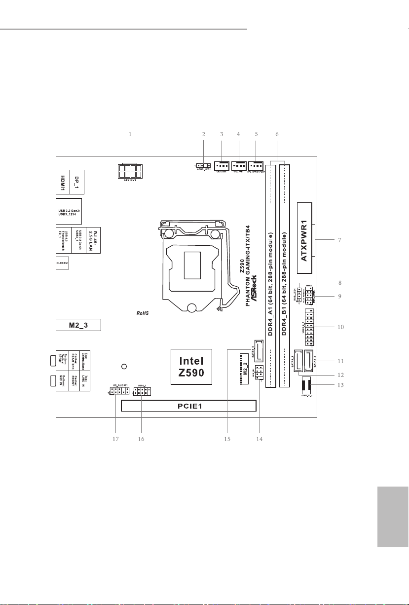
Motherboard Layout
Top Side View
Z590 Phantom Gaming-ITX/TB4
English
1
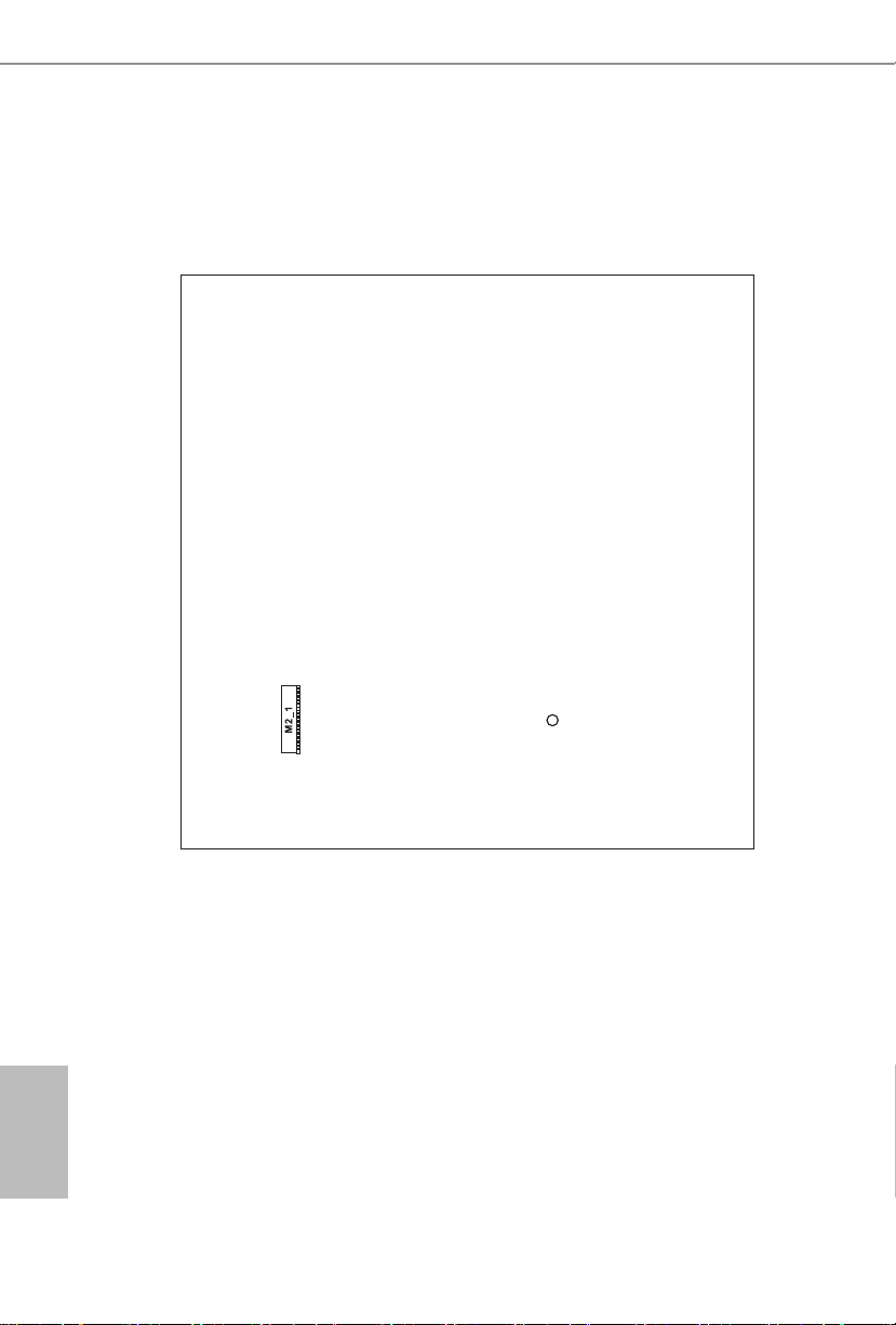
Back Side View
English
2

No. Description
1 ATX 12V Power Connector (ATX12V1)
2 Addressable LED Header (ADDR_LED1)
3 CPU Fan Connector (CPU_FAN1)
4 Chassis Fan Connector (CHA_FAN1)
5 CPU/Water Pump Fan Connector (CPU_OPT/W_PUMP)
6 2 x 288-pin DDR4 DIMM Slots (DDR4_A1, DDR4_B1)
7 ATX Power Connector (ATXPWR1)
8 RGB LED Header (RGB_LED1)
9 System Panel Header (PANEL1)
10 USB 3.2 Gen1 Header (USB3_6_7)
11 SATA3 Connector (SATA3_2)
12 SATA3 Connector (SATA3_1)
13 Front Panel Type C USB 3.2 Gen2x2 Header (USB31_TC_1)
14 Chassis Intrusion and Speaker Header (SPK_CI1)
15 SATA3 Connector (SATA3_0)
16 USB 2.0 Header (USB1_2)
17 Front Panel Audio Header (HD_AUDIO1)
Z590 Phantom Gaming-ITX/TB4
English
3
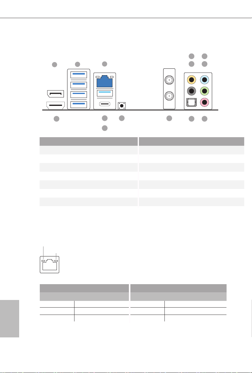
I/O Panel
1
6
2
3
547
English
14
1112
10
9 8
13
No. Description No. Description
1 DisplayPort 1.4 8 Microphone (Pink)
2 USB 3.2 Gen2 Type-A Ports (USB3_1234) 9 Optical SPDIF Out Port
3 2.5G LAN RJ-45 Port (Killer® E3100G)* 10 Antenna Ports
4 Central / Bass (Orange) 11 Clear CMOS Button
5 Rear Speaker (Black) 12 USB 3.2 Gen2 Type-A Port (USB3_5)
6 Line In (Light Blue) 13 USB 4.0 underboltTM 4 Type-C Port (TB_1)
7 Front Speaker (Lime)** 14 HDMI Port
* ere are two LEDs on each LAN port. Please refer to the table below for the LAN port LED indications.
ACT/LINK L ED
SPEED LE D
LAN Por t
Activity / Link LED Speed LED
Status Description Status Description
O No Link O 10Mbps connection
Blinking Data Activity Orange 100Mbps/1Gbps connection
On Link Green 2.5Gbps connection
4

Z590 Phantom Gaming-ITX/TB4
** If you use a 2- channel speaker, plea se connect the speake r’s plug into “Front Speaker Jack”. See the table below
for connection d etails in accordance w ith the type of speaker you use.
Audio Output
Channels
2 V -- -- --
4 V V -- --
6 V V V --
8 V V V V
Front Speaker
(No. 7)
Rear Speaker
(No. 5)
Central / Bass
(No. 4)
Line In
(No. 6)
English
5

802.11ax Wi-Fi 6E Module and ASRock WiFi 2.4/5/6 GHz Antennas
802.11ax Wi-Fi 6E + BT Module
is motherboard comes with an exclusive 802.11 a/b/g/n/ax Wi-Fi 6E + BT v5.2
module (pre-installed on the rear I/O panel) that oers support for 802.11 a/b/g/n/
ax Wi-Fi 6E connectivity standards and Bluetooth v5.2. Wi-Fi 6E + BT module is
an easy-to-use wireless local area network (WLAN) adapter to support Wi-Fi 6E
+ BT. Bluetooth v5.2 standard features Smart Ready technology that adds a whole
new class of functionality into the mobile devices. BT 5.2 also includes Low Energy
Technology and ensures extraordinary low power consumption for PCs.
* e transmission speed may vary according to the environment.
* Wi-Fi 6E (6GHz band) is not currently enabled by default due to the dierent
regulation status of each country. It will be activated (for supported countries)
through Windows Update and soware update once available. e update is
expected to be in the middle of 2021.
English
6
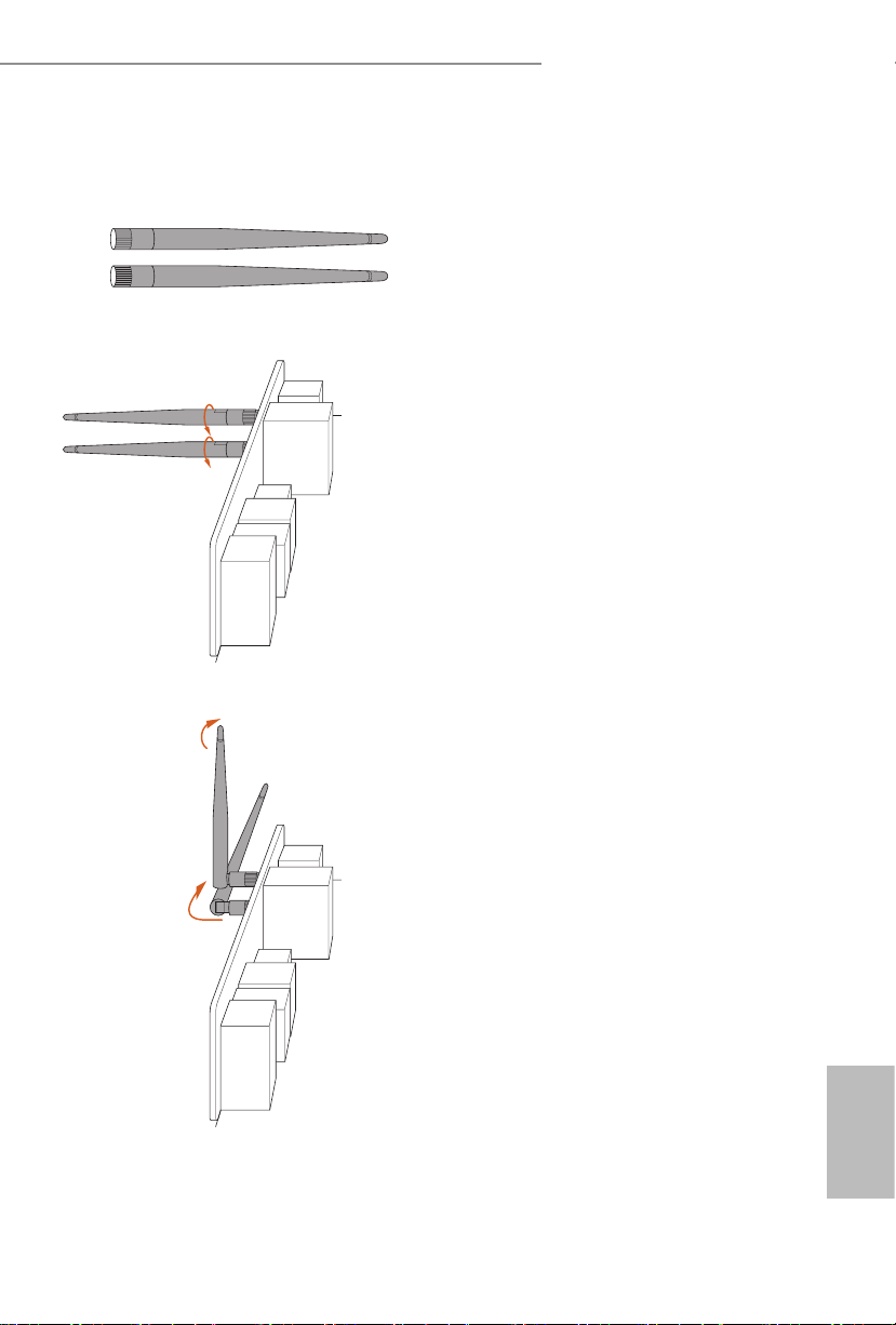
WiFi Antennas Installation Guide
Z590 Phantom Gaming-ITX/TB4
Step 1
Prepare the WiFi 2.4/5/6 GHz Antennas that
come with the package.
Step 2
Connect the two WiFi 2.4/5/6 GHz Antennas
to the antenna connectors. Turn the antenna
clockwise until it is securely connected.
Step 3
Set the WiFi 2.4/5/6 GHz Antenna as shown in
the illustration.
*You may need to adjust the direction of
the antenna for a stronger signal.
English
7

Chapter 1 Introduction
ank you for purchasing ASRock Z590 Phantom Gaming-ITX/TB4 motherboard,
a reliable motherboard produced under ASRock ’s consistently stringent quality
control. It delivers excellent performance with robust design conforming to
ASRock’s commitment to quality and endurance.
Becau se the motherboard specications and the BIOS soware might be updated, the
content of this documentation will be subject to change without notice. In case any
modications of this documentation occur, the updated version will be available on
ASRock’s website without further notice. If you require technical support related to
this motherboard, please vi sit our website for s pecic information about the model
you are using. You may nd the l atest VGA cards and CPU suppor t list on ASRock’s
website a s well. ASRock website http://www.a srock.com.
1.1 Package Contents
ASRock Z590 Phantom Gaming-ITX/TB4 Motherboard (Mini-ITX Form Factor)
•
ASRock Z590 Phantom Gaming-ITX/TB4 Quick Installation Guide
•
ASRock Z590 Phantom Gaming-ITX/TB4 Support CD
•
2 x Serial ATA (SATA) Data Cables (Optional)
•
2 x ASRock WiFi 2.4/5/6 GHz Antennas (Optional)
•
2 x Screws for M.2 Sockets (Optional)
•
English
8

1.2 Specications
Platform
CPU
Chipset
Memory
* 11th Gen Intel® CoreTM (i9/i7/i5) support DDR4 up to 3200;
CoreTM (i3), Pentium® and Celeron® support DDR4 up to 2666.
* 10th Gen Intel® CoreTM (i9/i7) support DDR4 up to 2933; CoreTM
(i5/i3), Pentium® and Celeron® support DDR4 up to 2666.
* Please refer to Memory Support List on ASRock's website for
more information. (http://www.asrock.com/)
Z590 Phantom Gaming-ITX/TB4
Mini-ITX Form Factor
•
10 Layer PCB
•
Supports 10th Gen Intel® CoreTM Processors and 11th Gen
•
Intel® CoreTM Processors (LGA1200)
Digi Power design
•
10 Power Phase design
•
Supports Intel® Turbo Boost Max 3.0 Technology
•
Supports Intel® K-Series unlocked CPUs
•
Intel® Z590
•
Dual Channel DDR4 Memory Technology
•
2 x DDR4 DIMM Slots
•
11th Gen Intel® CoreTM Processors support DDR4 non-ECC,
•
un-buered memory up to 4266+(OC)*
10th Gen Intel® CoreTM Processors support DDR4 non-ECC,
•
un-buered memory up to 4266+(OC)*
Supports ECC UDIMM memory modules (operate in non-
•
ECC mode)
Max. capacity of system memory: 64GB
•
Supports Intel® Extreme Memory Prole (XMP) 2.0
•
15μ Gold Contact in DIMM Slots
•
Expansion
Slot
11th Gen Intel® CoreTM Processors
1 x PCI Express 4.0 x16 Slot*
•
10th Gen Intel® CoreTM Processors
1 x PCI Express 3.0 x16 Slot*
•
* Supports PCIe riser cards to extend one x16 slot to two x8 slots
* Supports NVMe SSD as boot disks
1 x Vertical M.2 Socket (Key E) with the bundled WiFi-
•
802.11ax PCIe WiFi module (on the rear I/O)
15μ Gold Contact in VGA PCIe Slot (PCIE1)
•
English
9

Graphics
Intel® UHD Graphics Built-in Visuals and the VGA outputs
•
can be supported only with processors which are GPU
integrated.
11th Gen Intel® CoreTM Processors support Intel® Xe Graphics
•
Architecture (Gen 12). 10th Gen Intel® CoreTM Processors
support Gen 9 Graphics
Graphics, Media & Compute: Microso DirectX 12, OpenGL
•
4.5, Intel® Built In Visuals, Intel® Quick Sync Video, Hybrid /
Switchable Graphics, OpenCL 2.1
Display & Content Security: Rec. 2020 (Wide Color Gamut),
•
Microso PlayReady 3.0, UHD/HDR Blu-ray Disc
ree graphics output options: HDMI, DisplayPort 1.4 and
•
Intel® underboltTM 4 ports
Supports Triple Monitor
•
Supports Intel® underboltTM 4 with max. resolution up to
•
5K (5210x2880) @ 60Hz
Supports HDMI 2.0 with max. resolution up to 4K x 2K
•
(4096x2160) @ 60Hz
Supports DisplayPort 1.4 with max. resolution up to 5K
•
(5210x2880) @ 60Hz
Supports Auto Lip Sync, Deep Color (12bpc), xvYCC and
•
HBR (High Bit Rate Audio) with HDMI 2.0 Port (Compliant
HDMI monitor is required)
Supports HDCP 2.3 with HDMI 2.0, DisplayPort 1.4 and
•
Intel® underboltTM 4 Ports
* 11th Gen Intel® CoreTM Processors support HDMI 2.0. 10th Gen
Intel® CoreTM Processors support HDMI 1.4.
English
10
Audio
7.1 CH HD Audio with Content Protection (Realtek
•
ALC1220 Audio Codec)
Premium Blu-ray Audio support
•
Supports Surge Protection
•
Pure Power-In
•
Direct Drive Technology
•
PCB Isolate Shielding
•
Impedance Sensing on Rear Out port
•
Individual PCB Layers for R/L Audio Channel
•
Gold Audio Jacks
•
15μ Gold Audio Connector
•
Nahimic Audio
•

LAN
Wireless
LAN
Z590 Phantom Gaming-ITX/TB4
2.5 Gigabit LAN 10/100/1000/2500 Mb/s
•
Killer® E3100G
•
Supports Killer LAN Soware
•
Supports Killer DoubleShotTM Pro
•
Supports Wake-On-LAN
•
Supports Lightning/ESD Protection
•
Supports Energy Ecient Ethernet 802.3az
•
Supports PXE
•
Killer AX1675x 802.11ax Wi-Fi 6E Module
•
Supports IEEE 802.11a/b/g/n/ax
•
Supports Dual-Band 2x2 160MHz with extended 6GHz
•
band* support
* Wi-Fi 6E (6GHz band) is not currently enabled by default
due to the dierent regulation status of each country. It will be
activated (for supported countries) through Windows Update
and soware update once available. e update is expected to be
in the middle of 2021.
2 antennas to support 2 (Transmit) x 2 (Receive) diversity
•
technology
Supports Bluetooth 5.2 + High speed class II
•
Supports MU-MIMO
•
Supports Killer LAN Soware
•
Supports Killer DoubleShotTM Pro
•
Rear Panel
I/O
2 x Antenna Ports
•
1 x HDMI Port
•
1 x DisplayPort 1.4
•
1 x Optical SPDIF Out Port
•
5 x USB 3.2 Gen2 Type-A Ports (10 Gb/s) (Supports ESD
•
Protection)
1 x USB 4.0 underboltTM 4 Type-C Port (40 Gb/s for USB 4.0
•
protocol; 40Gb/s for underbolt protocol) (Supports ESD
Protection)
* Supports USB PD 2.0 up to 9V@3A (27W) / 5V@3A (15W)
charging
1 x RJ-45 LAN Port with LED (ACT/LINK LED and SPEED
•
LED)
1 x Clear CMOS Button
•
HD Audio Jacks: Rear Speaker / Central / Bass / Line in /
•
Front Speaker / Microphone (Gold Audio Jacks)
English
11

English
12
Storage
Connector
3 x SATA3 6.0 Gb/s Connectors, support RAID (RAID 0,
•
RAID 1, RAID 5, RAID 10, Intel Rapid Storage Technology
18), NCQ, AHCI and Hot Plug
1 x Hyper M.2 Socket (M2_2), supports M Key type 2280
•
M.2 PCI Express module up to Gen4x4 (64 Gb/s) (Only supported with 11th Gen Intel® CoreTM Processors)*
1 x Ultra M.2 Socket (M2_1), supports M Key type 2280 M.2
•
SATA3 6.0 Gb/s module and M.2 PCI Express module up to
Gen3 x4 (32 Gb/s)*
* Supports Intel® OptaneTM Technology
* Supports NVMe SSD as boot disks
1 x Chassis Intrusion and Speaker Header
•
1 x RGB LED Header
•
* Support in total up to 12V/3A, 36W LED Strip
1 x Addressable LED Header
•
* Support in total up to 5V/3A, 15W LED Strip
1 x CPU Fan Connector (4-pin)
•
* e CPU Fan Connector supports the CPU fan of maximum
1A (12W) fan power.
1 x CPU/Water Pump Fan Connector (4-pin) (Smart Fan
•
Speed Control)
* e CPU/Water Pump Fan supports the water cooler fan of
maximum 2A (24W) fan power.
* CPU_OPT/W_PUMP can auto detect if 3-pin or 4-pin fan is
in use.
1 x Chassis Fan Connector (4-pin)
•
* e Chassis Fan Connector supports the chassis fan of maximum 1A (12W) fan power.
1 x 24 pin ATX Power Connector (Hi-Density Power Con-
•
nector)
1 x 8 pin 12V Power Connector (Hi-Density Power Connec-
•
tor)
1 x Front Panel Audio Connector (15μ Gold Audio Connec-
•
tor)
1 x USB 2.0 Header (Supports 2 USB 2.0 ports) (Supports
•
ESD Protection)
1 x USB 3.2 Gen1 Header (Supports 2 USB 3.2 Gen1 ports)
•
(Supports ESD Protection)
1 x Front Panel Type C USB 3.2 Gen2x2 Header (20 Gb/s)
•
(Supports ESD Protection)

BIOS
Feature
Hardware
Monitor
OS
Z590 Phantom Gaming-ITX/TB4
AMI UEFI Legal BIOS with multilingual GUI support
•
ACPI 6.0 Compliant wake up events
•
SMBIOS 2.7 Support
•
CPU Core/Cache, DRAM, VPPM, VTTDDR, CPU PLL,
•
VCC PLL, PCH Voltage, VCCIO, VCCIO_Memory, VCCSA,
CPU Standby 1, CPU Internal PLL, GT PLL, Ring PLL,
System Agent PLL, Memory Controller PLL Voltage Multiadjustment
Fan Tachometer: CPU, CPU_OPT/Water Pump, Chassis
•
Fans
Quiet Fan (Auto adjust chassis fan speed by CPU tempera-
•
ture): CPU_OPT/Water Pump
Fan Multi-Speed Control: CPU, CPU_OPT/Water Pump,
•
Chassis Fans
CASE OPEN detection
•
Voltage monitoring: +12V, +5V, +3.3V, CPU Vcore, DRAM,
•
PCH, VCCSA, VCCIO, VCCIO_Memory
Microso® Windows® 10 64-bit
•
FCC, CE
Certications
* For detailed product information, please visit our website: http://ww w.asrock.com
Please realize that the re is a certain risk involved with overclocking, including
adjusting the setting in the BIOS, applying Untied Overclocking Technology, or using
third-party overclocking tool s. Overclocking may aect your system’s stability, or
even cause damage to the components and devices of your system. It should be done
at your own risk and expense. We are not responsible for possible damage caused by
overclocking.
•
ErP/EuP ready (ErP/EuP ready power supply is required)
•
English
13

Chapter 2 Installation
is is a Mini-ITX form factor motherboard. Before you install the motherboard,
study the conguration of your chassis to ensure that the motherboard ts into it.
Pre-installation Precautions
Take note of the following precautions before you install motherboard components
or change any motherboard settings.
Make sure to unplug the power cord before installing or removing the motherboard
•
components. Failure to do so may cause physical injuries and damages to motherboard
components.
In order to avoid damage from static electricity to the motherboard’s components,
•
NEVER place your motherboard directly on a carpet. Also remember to use a grounded
wrist strap or touch a safety grounded object before you handle the components.
Hold components by the edges and do not touch the ICs.
•
Whenever you uninstall any components, place them on a grounded anti-static pad or
•
in the bag that comes with the components.
When placing screws to secure the motherboard to the chassis, please do not over-
•
tighten the screws! Doing so may damage the motherboard.
English
14
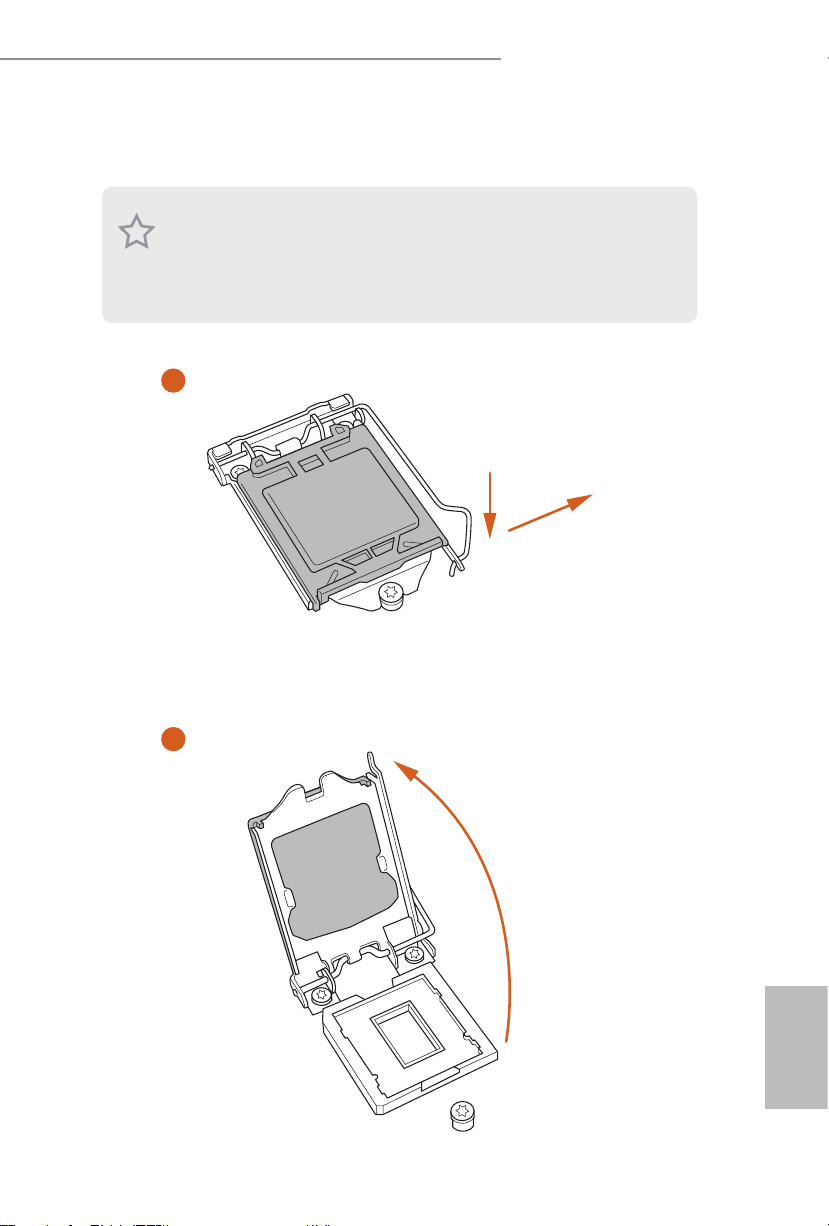
2.1 Installing the CPU
1. Before you insert the 120 0-Pin CPU into the socket, please check if the PnP ca p
is on the socket, if the CPU sur face is unclean, or if there are any b ent pins in the
socket. Do not force to insert the CPU into the socket if above situation is found.
Other wise, the CPU will be seriously d amaged.
2. Unplug all power cables be fore installing the CPU.
1
Z590 Phantom Gaming-ITX/TB4
A
B
2
English
15
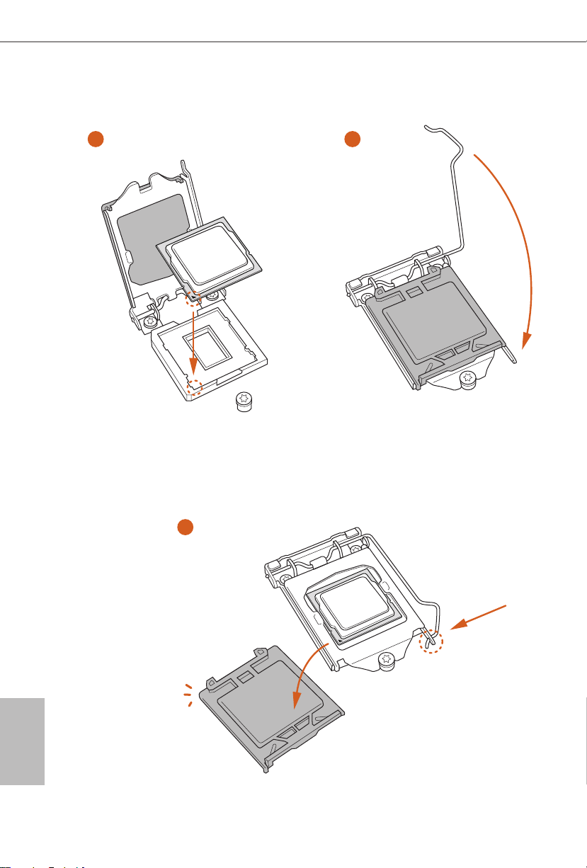
3
5
4
English
16

Z590 Phantom Gaming-ITX/TB4
Please save and replace the cover if the processor i s removed. e cover must be
placed if you wish to return the motherboard for aer service.
17
English
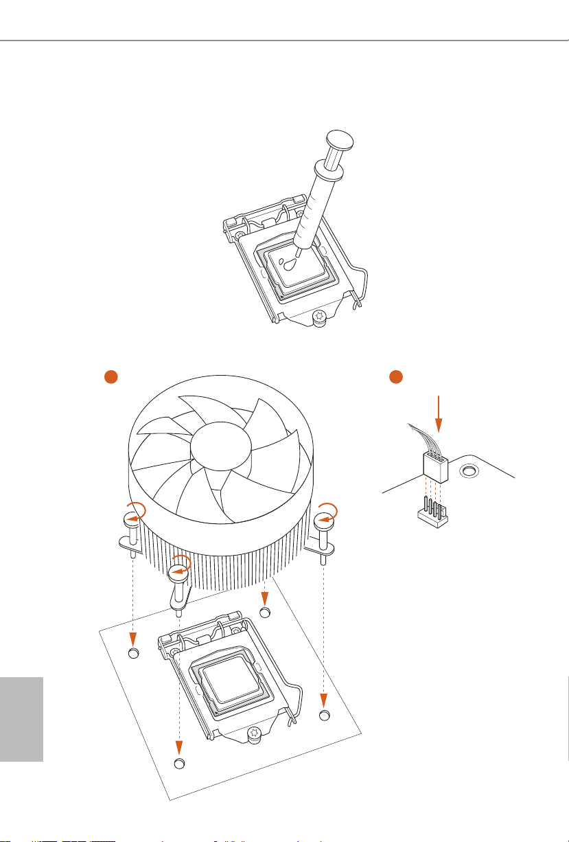
2.2 Installing the CPU Fan and Heatsink
1 2
English
18
CPU_FAN
Z590 Phantom Gaming-ITX/TB4
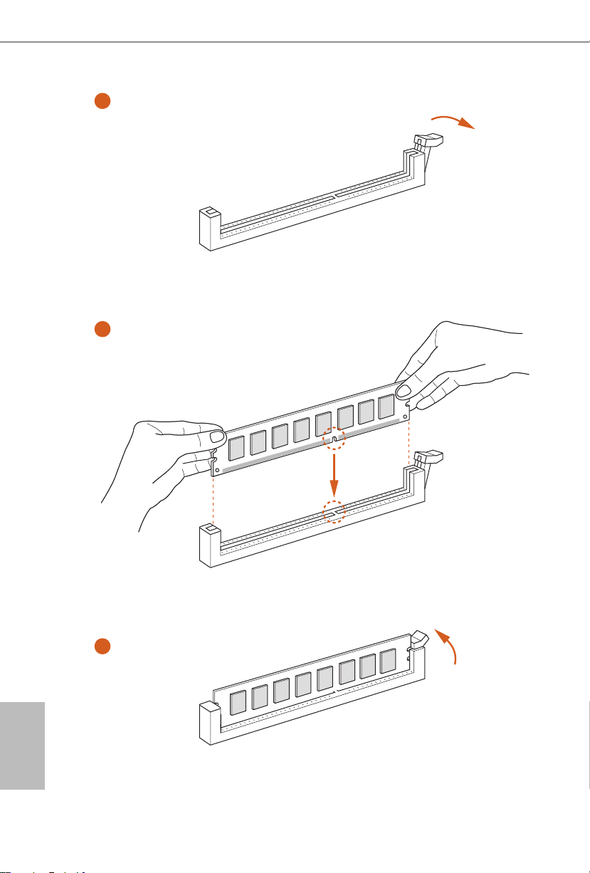
2.3 Installing Memory Modules (DIMM)
is motherboard provides two 288-pin DDR4 (Double Data Rate 4) DIMM slots,
and supports Dual Channel Memory Technology.
1. For dual channel conguration, you always need to install identical (the same
brand, speed , size and chip-type) DDR4 DIMM pairs.
2. It is unable to activate Dual Channel Memor y Technology with only one memory
module installed.
3. It is not allowed to install a DDR, DDR2 or DDR3 memory module into a DDR4
slot; otherwise, this motherboard and DIMM may be damaged.
e DIMM only ts in one correct orientation. It will cause permanent damage to
the mothe rboard and the DIMM if you force the DIMM into the slot at incor rect
orientation.
19
English
1
2
English
20
3

Z590 Phantom Gaming-ITX/TB4
2.4 Expansion Slots (PCI Express Slot)
ere is 1 PCI Express slot slot on the motherboard.
Before installing an ex pansion card, please make sure that the power supply is
switched o or the power cord is unplugged. Plea se read the documentation of the
expan sion card and make necessary hardware settings for the card before you start
the installation.
PCIe slots:
11th Gen Intel® CoreTM Processors:
PCIE1 (PCIe 4.0 x16 slot) is used for PCI Express x16 lane width graphics cards.
10th Gen Intel® CoreTM Processors:
PCIE1 (PCIe 3.0 x16 slot) is used for PCI Express x16 lane width graphics cards.
* Supports PCIe riser cards to extend one x16 slot to two x8 slots
21
English
2.5 Onboard Headers and Connectors
Onboard headers and connectors are NOT jumpers. Do NOT place jumper caps over
these headers and connectors. Placing jumper caps over the headers and connectors
will cause permanent damage to the motherboard.
System Panel Header
(9-pin PANEL1)
(see p.1, No. 9)
PWRBTN (Power Switch):
Connec t to the power switch on the chassi s front panel. You may congure the way to
turn o your system using the power switch.
RESET (Reset Switch):
Connec t to the reset switch on the chassis front panel. Press the reset sw itch to restart
the computer if the compute r freezes and fails to perform a normal restart.
PLED (Syste m Power LED):
Connec t to the power status indicator on the chassis front panel. e LED i s on when
the system is ope rating. e LED keeps blinking when the system i s in S1/S3 sleep
state. e LED is o when the system is in S4 sleep state or powered o (S5).
HDLED (Ha rd Drive Activity LED):
Connec t to the hard drive activity LED on the chassis front panel. e LED is on
when the hard drive i s reading or writing data.
e front panel design may dier by chassis. A front panel module mainly consists
of power switch, reset switch, power LED, hard dr ive activity LED, speak er and etc.
When connecting your chassis front panel module to this head er, make sure the wire
assig nments and the pin assig nments are matched correctly.
GND
PWR BT N #
PLE D-
PLE D+
GND
RES ET#
GND
HDL ED -
HDL ED +
1
Connect the power
switch, reset switch and
system status indicator on
the chassis to this header
according to the pin
assignments below. Note
the positive and negative
pins before connecting
the cables.
English
22
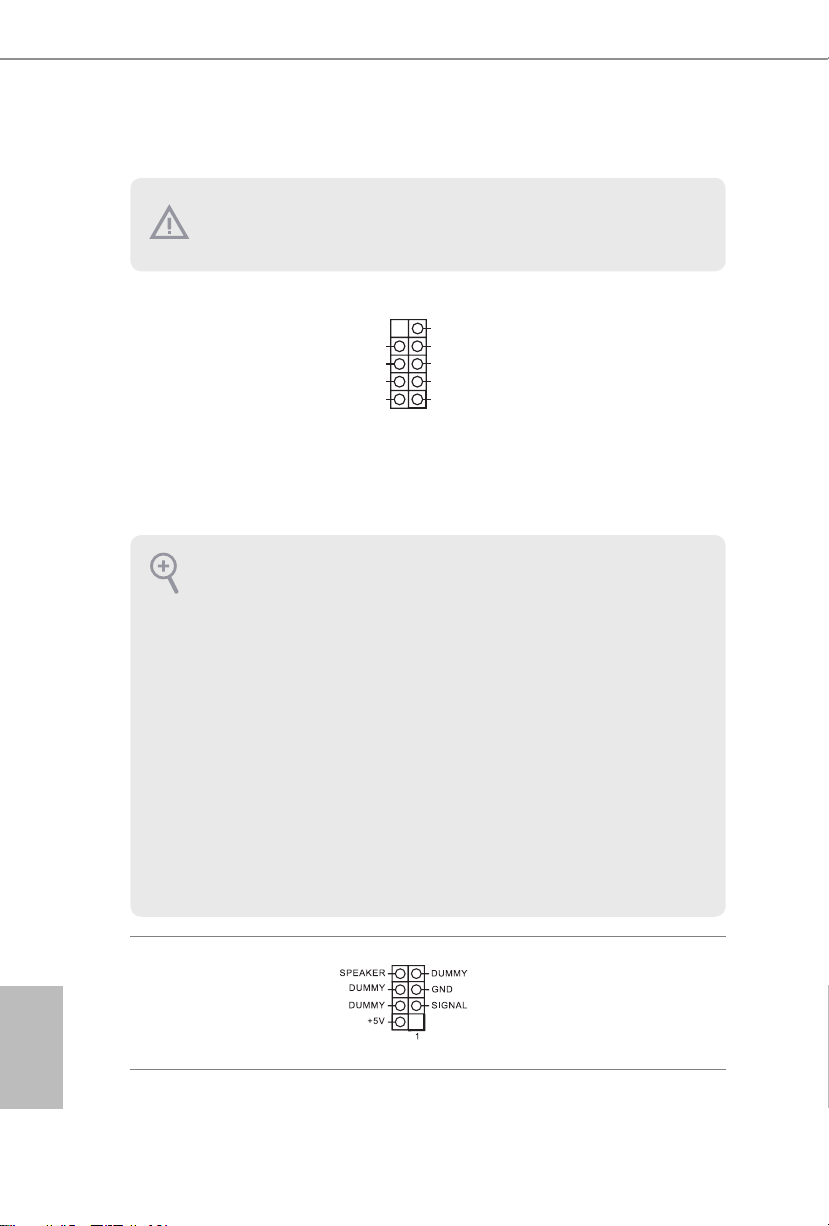
Chassis Intrusion and
Speaker Header
(7-pin SPK_CI1)
(see p.1, No. 14)
Please connect the
chassis intrusion and the
chassis speaker to this
header.
Z590 Phantom Gaming-ITX/TB4
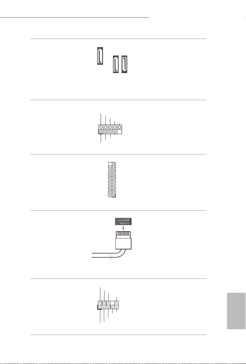
Serial ATA3 Connectors
(SATA3_0:
see p.1, No. 15)
(SATA3_1:
see p.1, No. 12)
(SATA3_2:
see p.1, No. 11)
USB 2.0 Header
(9-pin USB1_2)
(see p.1, No. 16)
USB 3.2 Gen1 Header
(19-pin USB3_6_7)
(see p.1, No. 10)
Front Panel Type C USB
3.2 Gen2x2 Header
(20-pin USB31_TC_1)
(see p.1, No. 13)
SATA3_0
USB _PW R
P-
1
P-
USB _PW R
Vbus
IntA _PA_S SRX-
IntA _PA_S SRX+
GND
IntA _PA_S STX-
IntA _PA_S STX+
GND
IntA _PA_D -
IntA _PA_D +
USB Type-C Cable
SATA3_1
P+
P+
GND
DUM MY
GND
VbusVbus
IntA _PB_ SSRX -
IntA _PB_ SSRX +
GND
IntA _PB_ SSTX -
IntA _PB_ SSTX +
GND
IntA _PB_ D-
IntA _PB_ D+
Dumm y
1
ese three SATA3
connectors support SATA
data cables for internal
storage devices with up to
SATA3_2
6.0 Gb/s data transfer rate.
ere is one USB2.0
header on this
motherboard. is USB
2.0 header can support
two ports.
ere is one header on
this motherboard. is
USB 3.2 Gen1 header can
support two ports.
ere is one Front
Panel Type C USB 3.2
Gen2x2 Header on this
motherboard. is header
is used for connecting a
USB 3.2 Gen2x2 module
for additional USB 3.2
Gen2x2 ports.
Front Panel Audio Header
(9-pin HD_AUDIO1)
(see p.1, No. 17)
1
GND
PRE SEN CE#
MIC 2_R
MIC 2_L
MIC _RE T
J_S ENS E
OUT 2_R
OUT _RE T
OUT 2_L
is header is for
connecting audio devices
to the front audio panel.
English
23

CPU_ FAN_SP EED
FAN_S PEED_ CONTR OL
4 3 2 1
4 3 2 1
1. High Denition Audio supports Jack Sensing, but the panel wire on the chassis
must support HDA to function correctly. Please follow the instructions in our
manual and chassis manual to install your system.
2. If you use an AC’97 audio panel, please install it to the front panel audio heade r by
the steps below:
A. Connect Mic_IN (MIC) to MIC2_ L.
B. Conne ct Audio_R (RIN) to OUT2_R and Audio_ L (LIN) to OUT2_ L.
C. Connect Ground (GND) to Ground (GND).
D. MIC_ RET and OUT_RET are for the HD audio panel only. You don’t need to
connect them for the AC’97 audio panel.
E. To activate the front mic, go to the “FrontMic” Tab in the Realtek Control panel
and adju st “Recording Volume”.
English
Chassis Fan Connector
(4-pin CHA_FAN1)
(see p.1, No. 4)
CPU Fan Connector
(4-pin CPU_FAN1)
(see p.1, No. 3)
CPU/Water Pump Fan
Connector
(4-pin CPU_OPT/W_
PUMP)
(see p.1, No. 5)
FAN _SP EED _C ONT ROL
CHA _FA N_S PE ED
GND
FAN_ VOLTA GE
CPU_ F
AN_S PEED
FAN_S PEED_ CONTR OL
4 3 2 1
+12 V
Please connect fan cables
to the fan connector and
match the black wire to
the ground pin.
GND
is motherboard provides a 4-Pin CPU fan
(Quiet Fan) connector.
If you plan to connect a
3-Pin CPU fan, please
connect it to Pin 1-3.
is motherboard
provides a 4-Pin water
cooling CPU fan
connector. If you plan
to connect a 3-Pin CPU
water cooler fan, please
connect it to Pin 1-3.
24
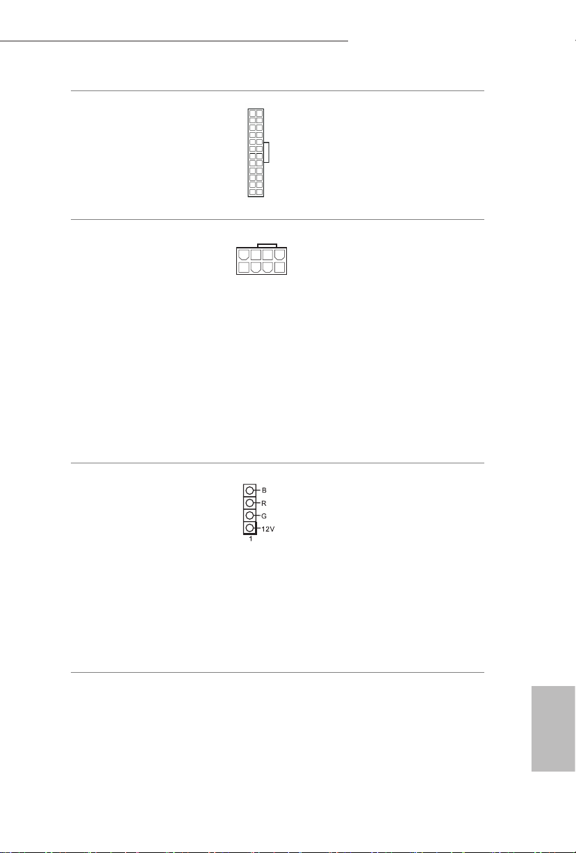
ATX Power Connector
1
(24-pin ATXPWR1)
(see p.1, No. 7)
Z590 Phantom Gaming-ITX/TB4
12
24
1
13
is motherboard provides a 24-pin ATX power
connector.
ATX 12V Power
Connector
(8-pin ATX12V1)
(see p.1, No. 1)
RGB LED Header
(4-pin RGB_LED1)
(see p.1, No. 8)
8 5
4
is motherboard
provides a 8-pin ATX 12V
power connector. To use a
4-pin ATX power supply,
please plug it along Pin 1
and Pin 5.
*Warning: Please make
sure that the power cable
connected is for the CPU
and not the graphics
card. Do not plug the
PCIe power cable to this
connector.
RGB header is used to connect
RGB LED extension cable which
allows users to choose from various LED lighting eects.
Caution: Never install the RGB
LED cable in the wrong orienta-
tion; otherwise, the cable may
be damaged.
* Please refer to page 36 for
further instructions on this
header.
English
25

Addressable LED Header
(3-pin ADDR_LED1)
(see p.1, No. 2)
1
VOU T
DO_ ADD R
GND
is header is used to connect
Addressable
LED extension cable
which allows users to choose
from various LED lighting
eects.
Caution: Never install the
Addressable LED cable in the
wrong orientation; otherwise,
the cable may be damaged.
* Please refer to page 37 for
further instructions on this
header.
English
26
 Loading...