


Version 1.0
Published July 2016
Copyright©2016 ASRock INC. All rights reserved.
Copyright Notice:
No part of this documentation may be reproduced, transcribed, transmitted, or
translated in any language, in any form or by any means, except duplication of
documentation by the purchaser for backup purpose, without written consent of
ASRock Inc.
Products and corporate names appearing in this documentation may or may not
be registered trademarks or copyrights of their respective companies, and are used
only for identication or explanation and to the owners’ benet, without intent to
infringe.
Disclaimer:
Specications and information contained in this documentation are furnished for
informational use only and subject to change without notice, and should not be
constructed as a commitment by ASRock. ASRock assumes no responsibility for
any errors or omissions that may appear in this documentation.
With respect to the contents of this documentation, ASRock does not provide
warranty of any kind, either expressed or implied, including but not limited to
the implied warranties or conditions of merchantability or tness for a particular
purpose.
In no event shall ASRock, its directors, ocers, employees, or agents be liable for
any indirect, special, incidental, or consequential damages (including damages for
loss of prots, loss of business, loss of data, interruption of business and the like),
even if ASRock has been advised of the possibility of such damages arising from any
defect or error in the documentation or product.
is device complies with Part 15 of the FCC Rules. Operation is subject to the following
two conditions:
(1) this device may not cause harmful interference, and
(2) this device must accept any interference received, including interference that
may cause undesired operation.
CALIFORNIA, USA ONLY
e Lithium battery adopted on this motherboard contains Perchlorate, a toxic substance
controlled in Perchlorate Best Management Practices (BMP) regulations passed by the
California Legislature. When you discard the Lithium battery in California, USA, please
follow the related regulations in advance.
“Perchlorate Material-special handling may apply, see www.dtsc.ca.gov/hazardouswaste/
perchlorate”
ASRock Website: http://www.asrock.com
AUSTRALIA ONLY
Our goods come with guarantees that cannot be excluded under the Australian Consumer
Law. You are entitled to a replacement or refund for a major failure and compensation for
any other reasonably foreseeable loss or damage caused by our goods. You are also entitled
to have the goods repaired or replaced if the goods fail to be of acceptable quality and the
failure does not amount to a major failure. If you require assistance please call ASRock Tel
: +886-2-28965588 ext.123 (Standard International call charges apply)
e terms HDMI™ and HDMI High-Denition Multimedia Interface, and the HDMI
logo are trademarks or registered trademarks of HDMI Licensing LLC in the United
States and other countries.
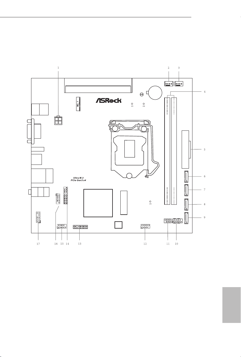
Motherboard Layout
Intel
Z170
DDR 4_B1 (6 4 bit, 28 8-pin mo dule)
DDR 4_A1 (6 4 bit, 28 8-pin mo dule)
ATXP WR 1
Top:
RJ-4 5
USB 2 .0
T: USB0
B: US B1
HDLED R ESET
PLED PW RBTN
PANEL1
1
USB_2_3
1
1
SPK_CI1
1
HD_AUD IO1
Z170 M-P IO2
RoH S
VGA 1
USB 3. 0
T: USB1
B: USB 2
CMO S
Bat tery
USB3_3_4
1
CPU_FAN1
1
TPMS1
PCI E xpres s 3.0
Fro nt USB 3. 0
Top:
LINE IN
Cente r:
FRONT
Botto m:
MIC IN
ATX12V1
SATA3_1
PCIE1
CHA_FAN1
BIOS
ROM
PS2
Keyb oard
PS2
Mous e
SATA3_2
M2_ 2
CLRMOS1
COM1
1
HDM I1
USB_4_5
1
SATA3_3
SATA3_4
Z170M-PIO2
English
1
No. Description
1 ATX 12V Power Connector (ATX12V1)
2 CPU Fan Connector (CPU_FAN1)
3 Chassis Fan Connector (CHA_FAN1)
4 2 x 288-pin DDR4 DIMM Slots (DDR4_A1, DDR4_B1)
5 ATX Power Connector (ATXPWR1)
6 SATA3 Connector (SATA3_4)
7 SATA3 Connector (SATA3_3)
8 SATA3 Connector (SATA3_2)
9 SATA3 Connector (SATA3_1)
10 System Panel Header (PANEL1)
11 Chassis Intrusion and Speaker Header (SPK_CI1)
12 USB 2.0 Header (USB_4_5)
13 TPM Header (TPMS1)
14 USB 3.0 Header (USB3_3_4)
15 COM Port Header (COM1)
16 USB 2.0 Header (USB_2_3)
17 Front Panel Audio Header (HD_AUDIO1)
English
2
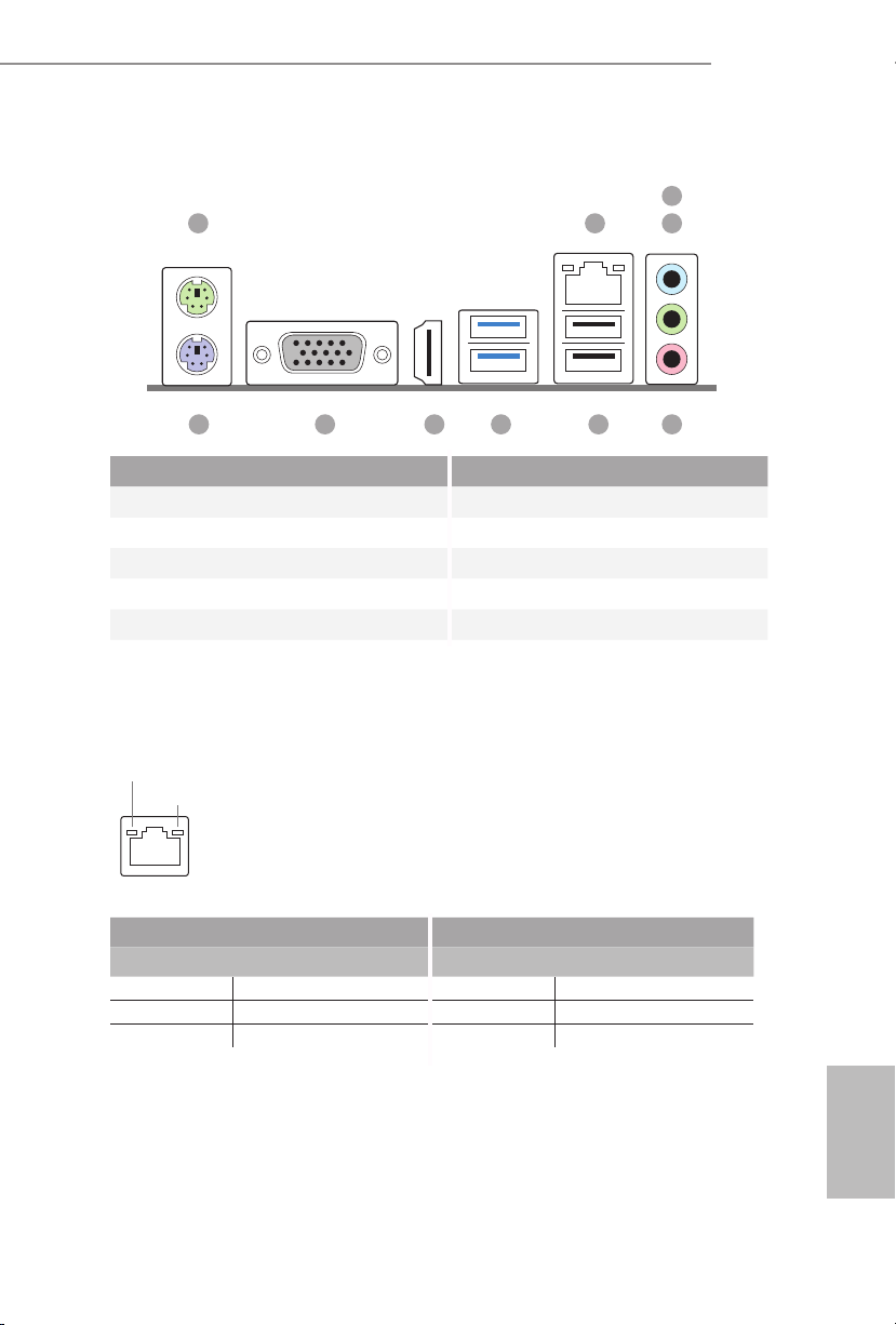
I/O Panel
1 2
Z170M-PIO2
3
4
10 56
No. Description No. Description
1 PS/2 Mouse Port 6 USB 2.0 Ports (USB01)***
2 LAN RJ-45 Port* 7 USB 3.0 Ports (USB3_12)
3 Line In (Light Blue)** 8 HDMI Port
4 Front Speaker (Lime)** 9 D-Sub Port
5 Microphone (Pink)** 10 PS/2 Keyboard Port
* ere are two LEDs on the LAN port. Please refer to the table below for the LAN port LED indications.
ACT/LINK L ED
SPEED LE D
LAN Por t
Activity / Link LED Speed LED
Status Description Status Description
O No Link O 10Mbps connection
Blinking Data Activity Orange 100Mbps connection
On Link Green 1Gbps connection
9
8
7
English
3
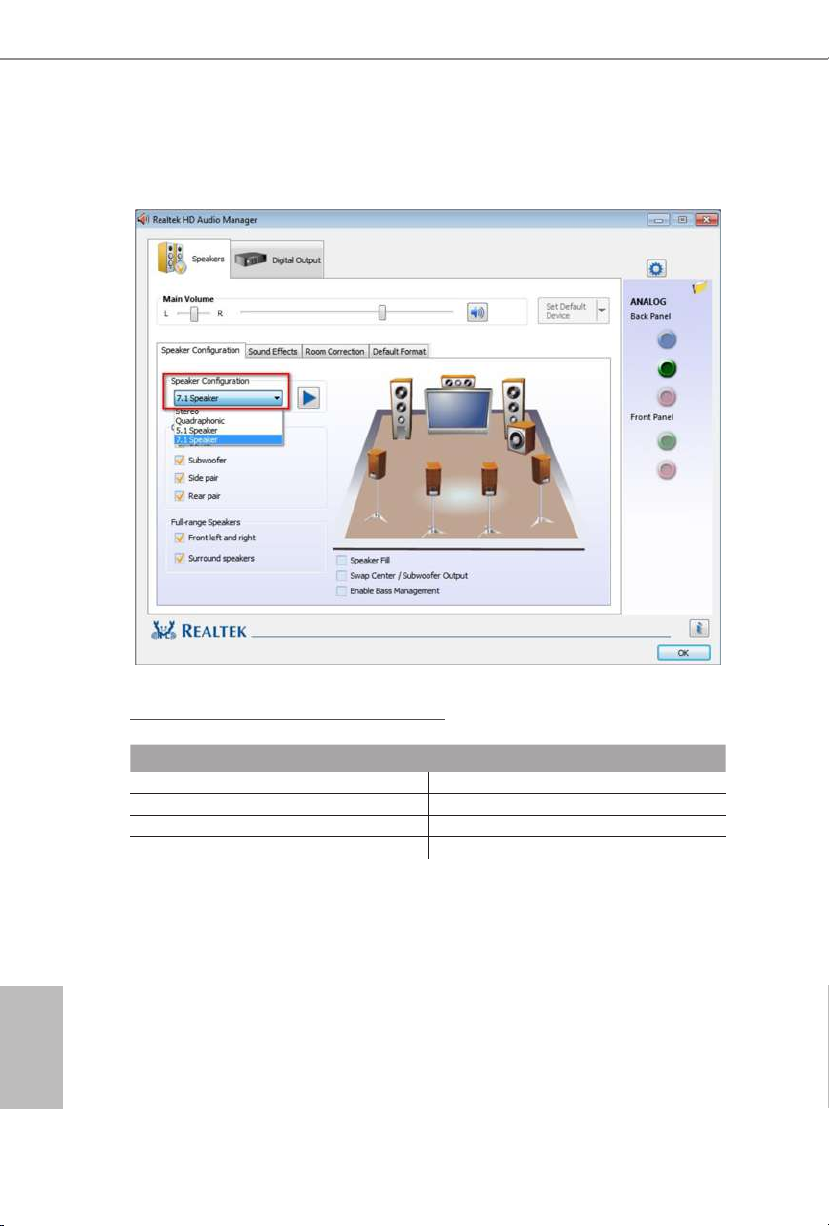
** To congure 7.1 CH HD Audio, it i s required to use an HD front panel audio module and enable the multichannel audio feature through the audio driver.
Please set Speaker Conguration to “7.1 Speaker”in the Realtek HD Audio Manager.
Function of the Audio Por ts in 7.1-channel Con guration:
English
4
Port Function
Light Blue (Rear panel) Rear Speaker Out
Lime (Rear panel) Front Speaker Out
Pink (Rear panel) Central /Subwoofer Speaker Out
Lime (Front panel) Side Speaker Out
*** ACPI wake-up function is supported on USB01 por ts only.

Chapter 1 Introduction
ank you for purchasing ASRock Z170M-PIO2 motherboard, a reliable
motherboard produced under ASRock’s consistently stringent quality control.
It delivers excellent performance with robust design conforming to ASRock’s
commitment to quality and endurance.
Becau se the motherboard specications and the BIOS soware might be updated, the
content of this documentation will be subject to change without notice. In case any
modications of this documentation occur, the updated version will be available on
ASRock’s website without further notice. If you require technical support related to
this motherboard, please vi sit our website for s pecic information about the model
you are using. You may nd the l atest VGA cards and CPU suppor t list on ASRock’s
website a s well. ASRock website http://www.a srock.com.
1.1 Package Contents
ASRock Z170M-PIO2 Motherboard (uDTX Form Factor)
•
ASRock Z170M-PIO2 Quick Installation Guide
•
ASRock Z170M-PIO2 Support CD
•
Serial ATA (SATA) Data Cable (Optional)
•
I/O Panel Shield (Optional)
•
2 x Screws for M.2 Socket (Optional)
•
Z170M-PIO2
English
5

1.2 Specications
Platform
CPU
Chipset
Memory
•
•
•
•
•
•
•
•
•
•
•
•
•
•
* 3466+(OC) memory frequency can only be achieved when a
single memory module is installed (Single channel memory).
* Please refer to Memory Support List on ASRock's website for
more information. (http://www.asrock.com/)
•
•
•
uDTX Form Factor supports PIO and Micro ATX
Solid Capacitor design
Supports 6th Generation Intel® CoreTM i7/i5/i3/Pentium®/
Celeron® Processors (Socket 1151)
Supports CPU up to 95W
Digi Power design
5 Power Phase design
Supports Intel® Turbo Boost 2.0 Technology
Supports Intel® K-Series unlocked CPUs
Supports ASRock BCLK Full-range Overclocking
Intel® Z170
Dual Channel DDR4 Memory Technology
2 x DDR4 DIMM Slots
Supports DDR4 3466+(OC)*/3200(OC)/2933(OC)/2800(OC)
/2400(OC)/2133 non-ECC, un-buered memory
Supports ECC UDIMM memory modules (operate in nonECC mode)
Max. capacity of system memory: 32GB
Supports Intel® Extreme Memory Prole (XMP) 2.0
15μ Gold Contact in DIMM Slots
English
6
Expansion
Slot
1 x Right Angle PCI Express 3.0 x16 Slot (PCIE1: x16 mode)*
•
* Supports NVMe SSD as boot disk
1 x M.2 Socket (Key E), supports type 2230 WiFi/BT module
•

Graphics
Intel® HD Graphics Built-in Visuals and the VGA outputs
•
can be supported only with processors which are GPU
integrated.
Supports Intel® HD Graphics Built-in Visuals : Intel® Quick
•
Sync Video with AVC, MVC (S3D) and MPEG-2 Full
HW Encode1, Intel® InTruTM 3D, Intel® Clear Video HD
Technology, Intel® InsiderTM, Intel® HD Graphics 510/530
Pixel Shader 5.0, DirectX 12
•
Max. shared memory 1024MB
•
* e size of maximum shared memory may vary from dierent
operating systems.
Dual graphics output: Support D-Sub and HDMI ports by
•
independent display controllers
Supports HDMI with max. resolution up to 4K x 2K
•
(4096x2160) @ 24Hz / (3840x2160) @ 30Hz
Supports D-Sub with max. resolution up to 1920x1200 @
•
60Hz
Supports Auto Lip Sync, Deep Color (12bpc), xvYCC and
•
HBR (High Bit Rate Audio) with HDMI Port (Compliant
HDMI monitor is required)
Supports Accelerated Media Codecs: HEVC, VP8, VP9
•
Supports HDCP with HDMI Port
•
Supports Full HD 1080p Blu-ray (BD) playback with HDMI
•
Port
Z170M-PIO2
Audio
LAN
7.1 CH HD Audio (Realtek ALC887 Audio Codec)
•
* To congure 7.1 CH HD Audio, it is required to use an HD
front panel audio module and enable the multi-channel audio
feature through the audio driver.
Supports Surge Protection (ASRock Full Spike Protection)
•
ELNA Audio Caps
•
PCIE x1 Gigabit LAN 10/100/1000 Mb/s
•
Realtek RTL8111GR
•
Supports Wake-On-WAN
•
Supports Wake-On-LAN
•
Supports Lightning/ESD Protection (ASRock Full Spike
•
Protection)
Supports LAN Cable Detection
•
Supports Energy Ecient Ethernet 802.3az
•
Supports PXE
•
English
7

English
Rear Panel
I/O
Storage
Connector
1 x PS/2 Mouse Port
•
1 x PS/2 Keyboard Port
•
1 x D-Sub Port
•
1 x HDMI Port
•
2 x USB 2.0 Ports (Supports ESD Protection (ASRock Full
•
Spike Protection))*
* ACPI wake-up function is supported on USB01 ports only.
2 x USB 3.0 Ports (Supports ESD Protection (ASRock Full
•
Spike Protection))
1 x RJ-45 LAN Port with LED (ACT/LINK LED and SPEED
•
LED)
HD Audio Jacks: Line in / Front Speaker / Microphone
•
4 x SATA3 6.0 Gb/s Connectors, support RAID (RAID 0,
•
RAID 1, RAID 5, RAID 10, Intel Rapid Storage Technology
14 and Intel Smart Response Technology), NCQ, AHCI and
Hot Plug
1 x Ultra M.2 Socket, supports type 2260/2280 M.2 SATA3
•
6.0 Gb/s module and M.2 PCI Express module up to Gen3 x4
(32 Gb/s)*
* Supports NVMe SSD as boot disks
* Supports ASRock U.2 Kit
1 x COM Port Header
•
1 x TPM Header
•
1 x Chassis Intrusion and Speaker Header
•
1 x CPU Fan Connector (4-pin)
•
1 x Chassis Fan Connector (4-pin)
•
* e CPU Fan Connector supports the CPU fan of maximum
1A (12W) fan power.
1 x 24 pin ATX Power Connector
•
1 x 4 pin 12V Power Connector
•
1 x Front Panel Audio Connector
•
2 x USB 2.0 Headers (Support 4 USB 2.0 ports) (Supports
•
ESD Protection (ASRock Full Spike Protection))
1 x USB 3.0 Header (Supports 2 USB 3.0 ports) (Supports
•
ESD Protection (ASRock Full Spike Protection))
8
BIOS
Feature
Hardware
Monitor
OS
AMI UEFI Legal BIOS with multilingual GUI support
•
ACPI 5.0 Compliant wake up events
•
SMBIOS 2.7 Support
•
DRAM, PCH 1.0V, VCCSA Voltage Multi-adjustment
•
CPU/Chassis temperature sensing
•
CPU/Chassis Fan Tachometer
•
CPU/Chassis Quiet Fan (Auto adjust chassis fan speed by
•
CPU temperature)
CPU/Chassis Fan multi-speed control
•
CASE OPEN detection
•
Voltage monitoring: +12V, +5V, +3.3V, CPU Vcore, DRAM,
•
PCH 1.0V, VCCSA
Microso® Windows® 10 64-bit / 8.1 64-bit / 7 32-bit / 7 64-
•
bit
* To install Windows® 7 OS, a modied installation disk with
xHCI drivers packed into the ISO le is required. Please refer to
page 121 for more detailed instructions.
* For the updated Windows® 10 driver, please visit ASRock ’s
website for details: http://www.asrock.com
Z170M-PIO2
FCC, CE, WHQL
Certications
* For detailed product information, please visit our website: http://ww w.asrock.com
Please realize that the re is a certain risk involved with overclocking, including
adjusting the setting in the BIOS, applying Untied Overclocking Technology, or using
third-party overclocking tool s. Overclocking may aect your system’s stability, or
even cause damage to the components and devices of your system. It should be done
at your own risk and expense. We are not responsible for possible damage caused by
overclocking.
•
ErP/EuP Ready (ErP/EuP ready power supply is required)
•
English
9
1.3 Onboard Headers and Connectors
Onboard headers and connectors are NOT jumpers. Do NOT place jumper caps over
these headers and connectors. Placing jumper caps over the headers and connectors
will cause permanent damage to the motherboard.
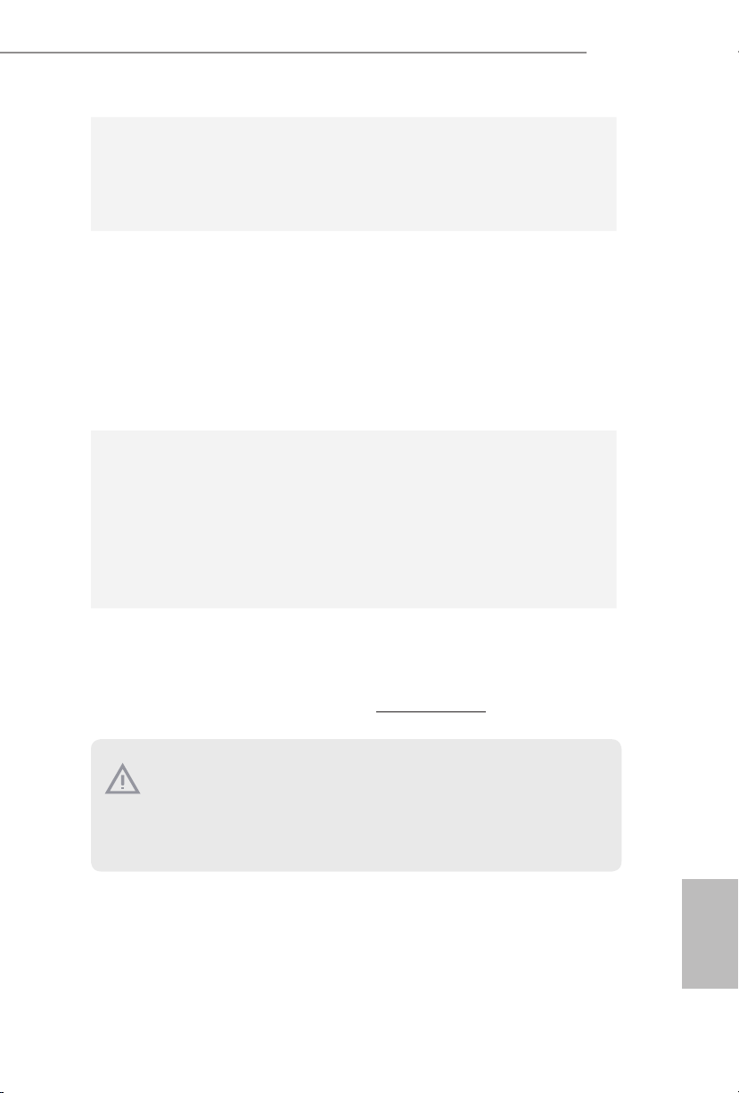
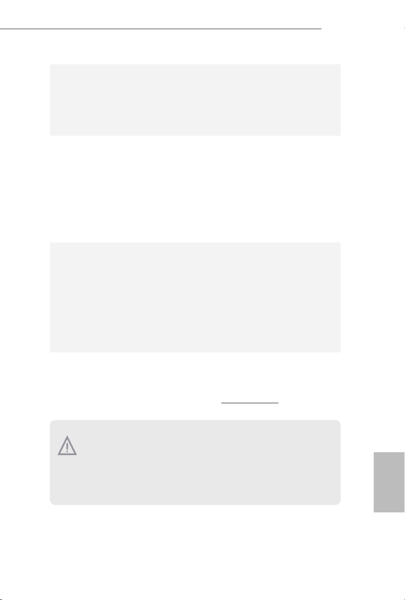
System Panel Header
(9-pin PANEL1)
(see p.1, No. 10)
PWRBTN (Power Switch):
Connec t to the power switch on the chassi s front panel. You may congure the way to
turn o your system using the power switch.
RESET (Reset Switch):
Connec t to the reset switch on the chassis front panel. Press the reset sw itch to restart
the computer if the compute r freezes and fails to perform a normal restart.
PLED (Syste m Power LED):
Connec t to the power status indicator on the chassis front panel. e LED i s on when
the system is ope rating. e LED keeps blinking when the system i s in S1/S3 sleep
state. e LED is o when the system is in S4 sleep state or powered o (S5).
HDLED (Ha rd Drive Activity LED):
Connec t to the hard drive activity LED on the chassis front panel. e LED is on
when the hard drive i s reading or writing data.
e front panel design may dier by chassis. A front panel module mainly consists
of power switch, reset switch, power LED, hard dr ive activity LED, speak er and etc.
When connecting your chassis front panel module to this head er, make sure the wire
assig nments and the pin assig nments are matched correctly.
1
PLE D+
PLE D-
HDL ED-
HDL ED+
PWR BTN#
GND
GND
RES ET#
GND
Connect the power
switch, reset switch and
system status indicator on
the chassis to this header
according to the pin
assignments below. Note
the positive and negative
pins before connecting
the cables.
English
10
Z170M-PIO2
1
SPE AKE R
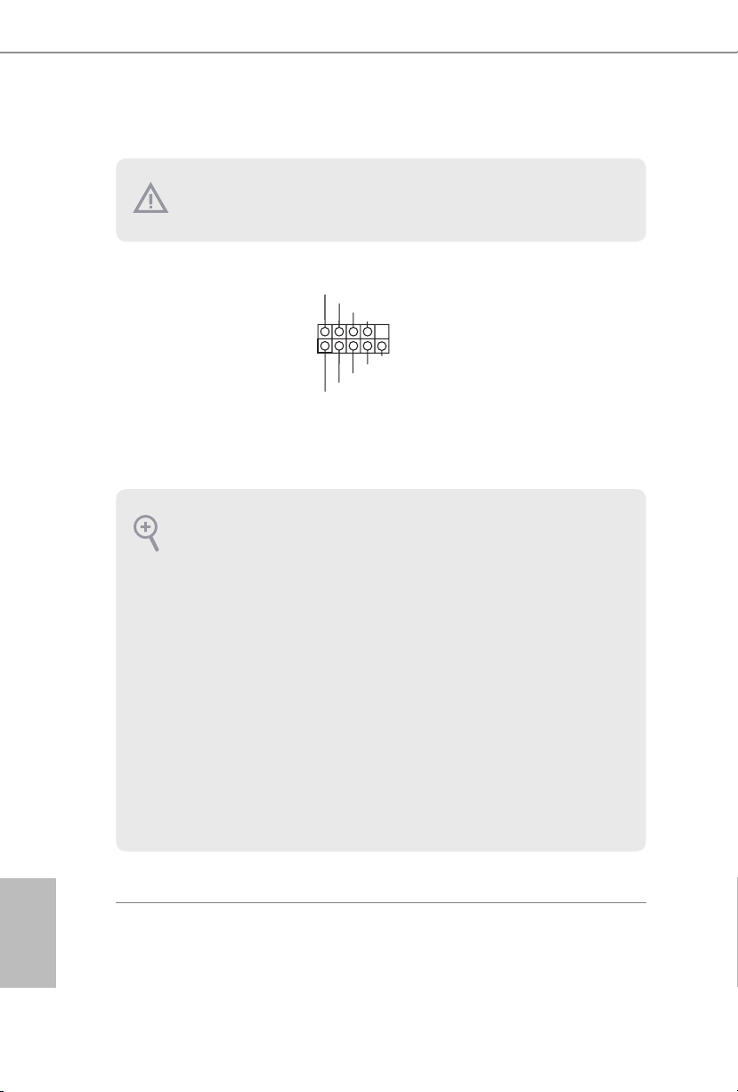
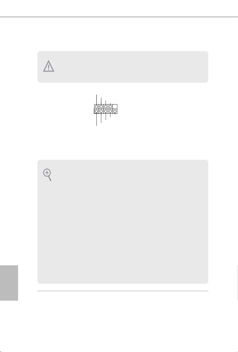
Chassis Intrusion and
Speaker Header
(7-pin SPK_CI1)
(see p.1, No. 11)
Serial ATA3 Connectors
(SATA3_1: see p.1, No. 9)
(SATA3_2: see p.1, No. 8)
(SATA3_3: see p.1, No. 7)
(SATA3_4: see p.1, No. 6)
USB 2.0 Headers
(9-pin USB_2_3)
(see p.1, No. 16)
(9-pin USB_4_5)
(see p.1, No. 12)
DUM MY
+5V
1
SIG NAL
USB _P WR
P-
P+
GND GND
USB _PW R
DUM MY
P-
P+
GND
DUM MY
GND
SATA3_1 SATA3_2 SATA3_3 SATA3_4
USB _P WR
P-
P+
DUM MY
DUM MY
Please connect the
chassis intrusion and the
chassis speaker to this
header.
ese four SATA3
connectors support SATA
data cables for internal
storage devices with up to
6.0 Gb/s data transfer rate.
ere are two headers
on this motherboard.
Each USB 2.0 header can
support two ports.
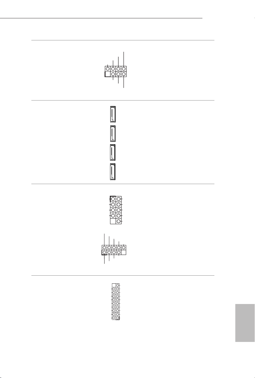
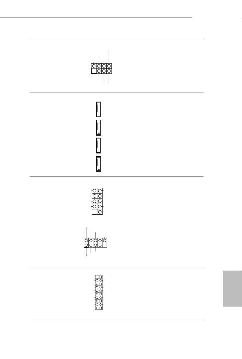
USB 3.0 Header
(19-pin USB3_3_4)
(see p.1, No. 14)
1
USB _PW R
Vbus
IntA _PA_SS RX-
IntA _PA_SS RX+
GND
IntA _PA_SS TX-
IntA _PA_SS TX+
GND
IntA _PA_D-
IntA _PA_D+
GND
P+
P-
VbusVbus
IntA _PB_S SRX-
IntA _PB_S SRX+
GND
IntA _PB_S STX-
IntA _PB_S STX+
GND
IntA _PB_D -
IntA _PB_D +
Dumm y
1
Besides two USB 3.0 ports
on the I/O panel, there
is one header on this
motherboard. Each USB
3.0 header can support
two ports.
English
11

Front Panel Audio Header
GND
FAN_V OLTAGE_ CONTR OL
FAN_S PEED
FAN_S PEED_ CONTR OL
GND
FAN_V OLTAGE_ CONTR OL
FAN_S PEED
FAN_S PEED_ CONTR OL
(9-pin HD_AUDIO1)
(see p.1, No. 17)
1. High De nition Audio supports Jack Sensing, but the panel wire on the chassis
must support HDA to function correctly. Please follow the instructions in our
manual and chassis manual to install your system.
2. If you use an AC’97 audio panel, please install it to the front panel audio header by
the steps below:
A. Connect Mic_IN (MIC) to MIC2_ L.
B. Conne ct Audio_R (RIN) to OUT2_R and Audio_ L (LIN) to OUT2_ L.
C. Connect Ground (GND) to Ground (GND).
D. MIC_ RET and OUT_RET are for the HD audio panel only. You don’t need to
connect them for the AC’97 audio panel.
E. To activate the front mic, go to the “FrontMic” Tab in the Realtek Control panel
and adju st “Recording Volume”.
OUT _R ET
MIC _R ET
PRE SE NCE #
GN D
1
OUT 2_ L
J_S EN SE
OUT 2_ R
MIC 2_ R
MIC 2_ L
is header is for
connecting audio devices
to the front audio panel.
English
12
Chassis Fan Connector
(4-pin CHA_FAN1)
(see p.1, No. 3)
CPU Fan Connector
(4-pin CPU_FAN1)
(see p.1, No. 2)
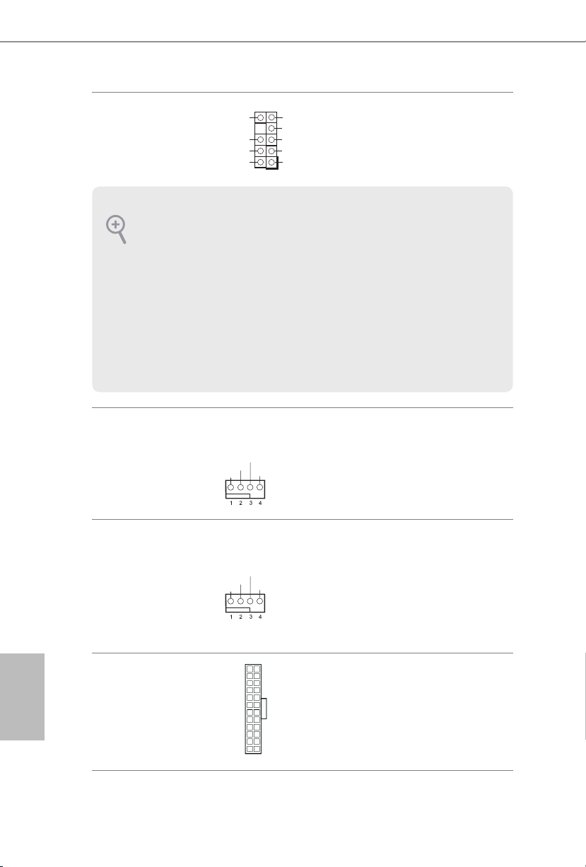
ATX Power Connector
(24-pin ATXPWR1)
(see p.1, No. 5)
Please connect fan cables
to the fan connector and
match the black wire to
the ground pin.
is motherboard provides a 4-Pin CPU fan
(Quiet Fan) connector.
If you plan to connect a
3-Pin CPU fan, please
connect it to Pin 1-3.
24
12
is motherboard provides a 24-pin ATX power
connector. To use a 20-pin
ATX power supply, please
plug it along Pin 1 and Pin
1
13
13.
Z170M-PIO2
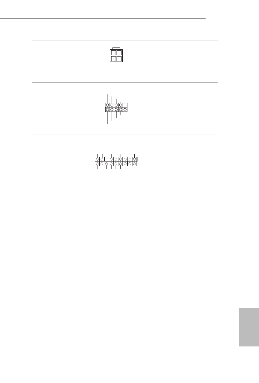
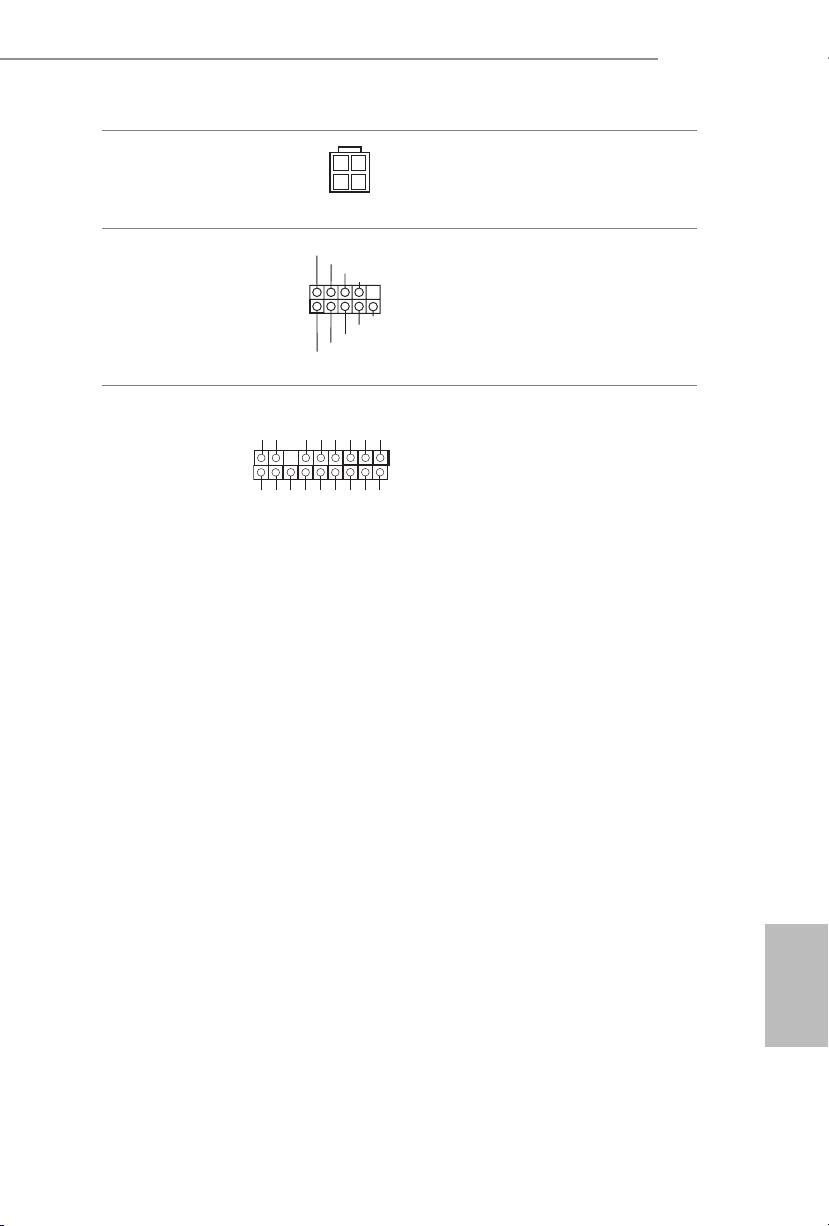
ATX 12V Power
Connector
(4-pin ATX12V1)
(see p.1, No. 1)
Serial Port Header
(9-pin COM1)
(see p.1, No. 15)
TPM Header
(17-pin TPMS1)
(see p.1, No. 13)
is motherboard
provides a 4-pin ATX 12V
power connector.
1
RRXD 1
TTXD 1
DDCD #1
DDTR #1
DDSR #1
GND
CCTS #1
RRI# 1
RRTS #1
is COM1 header
supports a serial port
module.
is connector supports Trusted
GN D
LAD 0
+3 V
+3V S B
D
GN
GN D
LAD 1
SER IRQ #
S_P WRD WN #
PC ICL K
LAD 3
PC IRS T #
FRA M E
Platform Module (TPM) system,
1
which can securely store keys,
digital certicates, passwords,
GN D
LAD 2
and data. A TPM system also
helps enhance network security,
SMB _CL K_M AIN
SMB _DA TA_ MAI N
protects digital identities, and
ensures platform integrity.
13
English
1.4 M.2_SSD (NGFF) Module Installation Guide
The M.2, also known as the Next Generation Form Factor (NGFF), is a small size and
versatile card edge connector that aims to replace mPCIe and mSATA. The Ultra M.2
Socket (M2_1) supports M.2 PCI Express module up to Gen3 x4 (32 Gb/s).
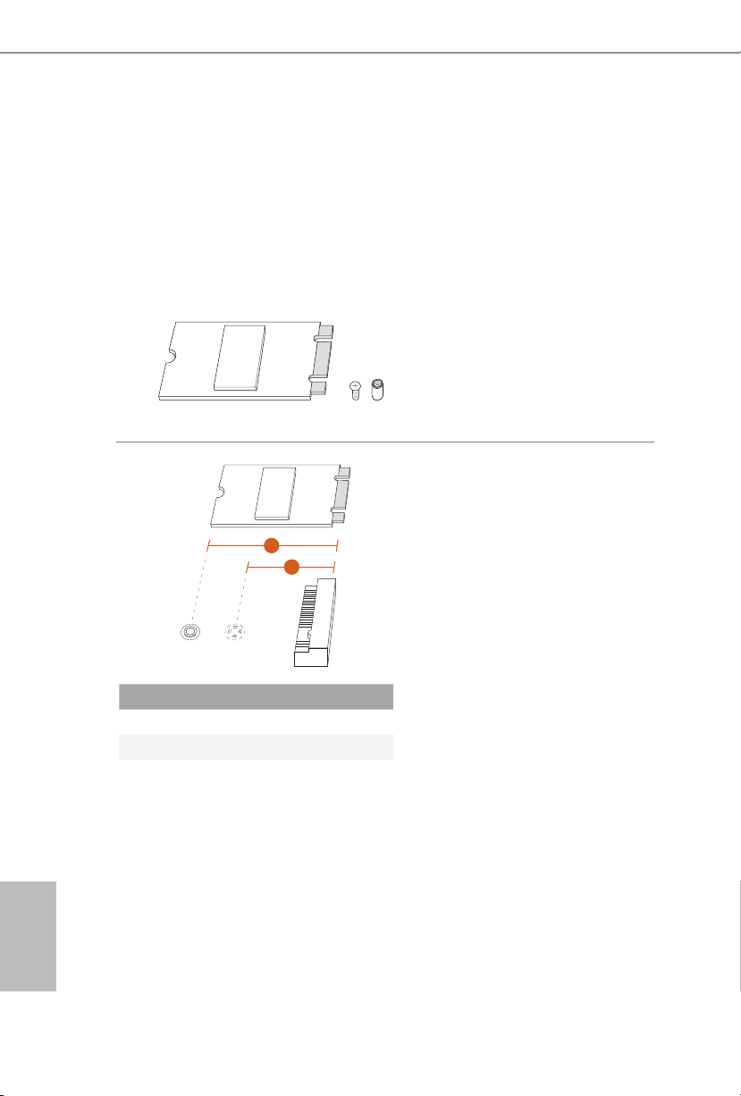
Installing the M.2_SSD (NGFF) Module
Step 1
is motherboard supports M.2_SSD
(NGFF) module type 2260 and 2280
only. Prepare a proper PCB lent h of
module, the screw and the stando.
Step 2
Depending on the PCB type and
length of your M.2_SSD (NGFF)
2
1
A
B
module, nd the corresponding nut
location to be used.
English
14
No. 1 2
Nut Location A B
PCB Length 6cm 8cm
Module Type Type2260 Type 2280
Z170M-PIO2
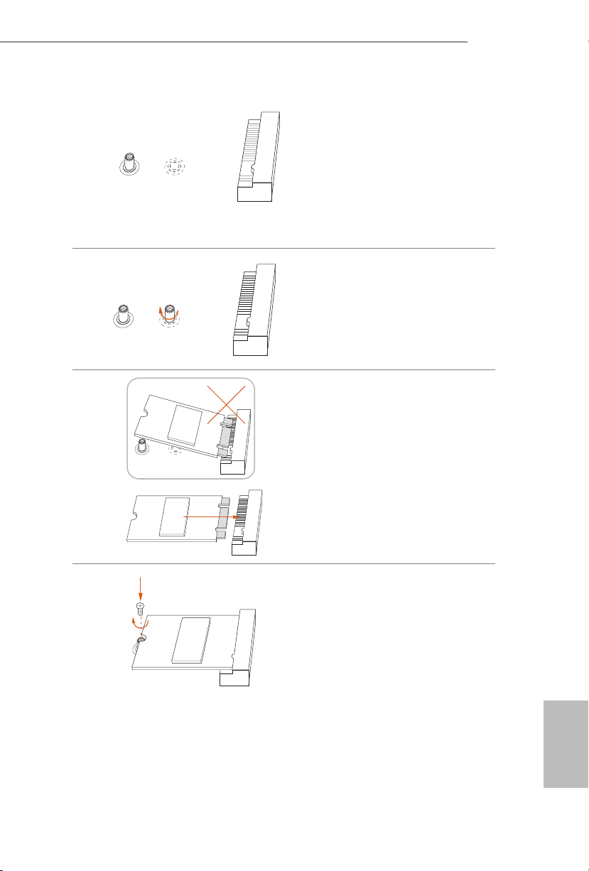
Step 3
e stando is placed at the nut
location B by default. Skip Step 4 and
B
B
A
A
A
B
go straight to Step 5 if your M.2_SSD
(NGFF) module is type 2280. If your
M.2_SSD (NGFF) module is type
2260, go to Step 4.
Step 4
Peel o the yellow protective lm on
the nut location A. Hand tighten the
stando into the nut location A on
the motherboard.
Step 5
Align and gently insert the M.2
(NGFF) SSD module into the M.2
slot. Please be aware that the M.2
(NGFF) SSD module only ts in one
orientation.
AB
Step 6
Tighten the screw with a screwdriver
to secure the module into place.
Please do not overtighten the screw
AB
as this might damage the module.
English
15
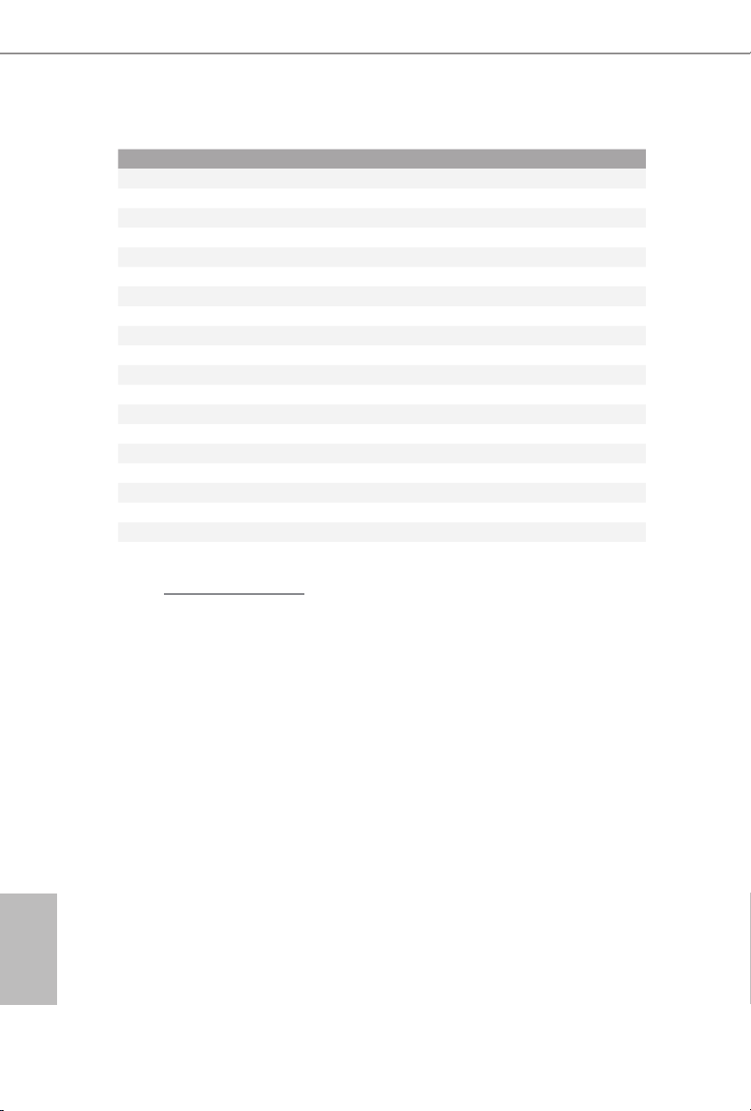
M.2_SSD (NGFF) Module Support List
Vendor Size Interface Length P/N
ADATA 128GB SATA3 2280 AXNS381E-128GM-B
ADATA 256GB SATA3 2280 AXNS381E-256GM-B
ADATA 32GB SATA3 2230 AXNS330E-32GM-B
Crucial 120GB SATA3 2280 CT120M500SSD4
Crucial 240GB SATA3 2280 CT240M500SSD4
Intel 80GB SATA3 2280 Intel SSDSCKGW080A401/80G
Kingston 120GB SATA3 2280 SM2280S3
Kingston 480GB PCIe2 x4 2280 SH2280S3/480G
Plextor 256GB PCIe 2280 PX-G256M6e
Plextor 512GB PCIe 2280 PX-G512M6e
Samsung 256GB PCIe3 x4 2280 SM951 (MZHPV256HDGL)
Samsung 512GB PCIe3 x4 2280 SM951 (MZHPV512HDGL)
Samsung 512GB PCIe x4 2280 XP941-512G (MZHPU512HCGL)
SanDisk 128GB PCIe 2260 SD6PP4M-128G
SanDisk 256GB PCIe 2260 SD6PP4M-256G
Team 128GB SATA3 2280 TM8PS4128GMC105
Team 256GB SATA3 2280 TM8PS4256GMC105
Transcend 512GB SATA3 2280 TS512GMTS800
Transcend 512GB SATA3 2260 TS512GMTS600
For the latest updates of M.2_SSD (NFGG) module support list, please visit our website for
details: http://www.asrock.com
English
16

1 Einleitung
Vielen Dank, dass Sie sich für das Z170M-PIO2 von ASRock entschieden haben – ein
zuverlässiges Motherboard, das konsequent unter der strengen Qualitätskontrolle von
ASRock hergestellt wurde. Es liefert ausgezeichnete Leistung mit robustem Design,
das ASRock Streben nach Qualität und Beständigkeit erfüllt.
Da die technischen Daten des Motherboards sowie die BIOS-Soware aktualisiert
werden können, kann der Inhalt dieser Dokumentation ohne Ankündigung geändert
werden. Falls diese Dokumentation irgendwelchen Änderungen unterliegt, wird die aktualisierte Version ohne weitere Hinweise auf der ASRock-Webseite zur Verfügung gestellt.
Sollten Sie technische Hilfe in Bezug auf dieses Motherboard benötigen, erhalten Sie auf
unserer Webseite spezischen Informationen über das von Ihnen verwendete Modell.
Auch nden Sie eine aktuelle Liste unterstützter VGA-Karten und Prozessoren auf der
ASRock-Webseite: ASRock-Website http://www.asrock.com.
1.1 Lieferumfang
ASRock Z170M-PIO2-Motherboard (uDTX-Formfaktor)
•
ASRock Z170M-PIO2-Schnellinstallationsanleitung
•
ASRock Z170M-PIO2-Support-CD
•
Serial-ATA- (SATA) Datenkabel (optional)
•
E/A-Blendenabschirmung (optional)
•
2 x Schraube für M.2-Sockel (optional)
•
Z170M-PIO2
17
Deutsch

1.2 Technische Daten
uDTX-Formfaktor unterstützt PIO und Micro ATX
Plattform
Prozessor
Chipsatz
Speicher
•
Feststoondensator-Design
•
Unterstützt die Prozessoren Intel® CoreTM i7/i5/i3/Pentium®/
•
Celeron® der 6. Generation (Sockel 1151)
Unterstützt CPU bis 95W
•
Digi Power design
•
5-Leistungsphasendesign
•
Unterstützt Intel® Turbo Boost 2.0-Technologie
•
Unterstützt CPUs mit freiem Multiplikator der Intel® K-Serie
•
Unterstützt ASRock BCLK-Übertaktung (voller Bereich)
•
Intel® Z170
•
Dualkanal-DDR4-Speichertechnologie
•
2 x DDR4-DIMM-Steckplätze
•
Unterstützt DDR4 3466+(OC)*/3200(OC)/2933(OC)/2800
•
(OC)/ 2400(OC)/2133 non-ECC, ungepuerter Speicher
Unterstützt ECC-UDIMM-Speichermodule (Betrieb im
•
Non-ECC-Modus)
* Speicherfrequenz von 3466+ (OC) kann nur erzielt
werden, wenn ein einzelnes Speichermodul installiert ist
(Einzelkanalspeicher).
* Weitere Informationen nden Sie in der
Speicherkompatibilitätsliste auf der ASRock-Webseite.
(http://www.asrock.com/)
Systemspeicher, max. Kapazität: 32GB
•
Unterstützt Intel® Extreme Memory Prole (XMP) 2.0
•
15-μ-Goldkontakt in DIMM-Steckplätze
•
Deutsch
18
Erweiterungssteckplatz
1 x Rechter Winkel PCI-Express 3.0-x16-Steckplatz (PCIE1:
•
x16-Modus)*
* Unterstützt NVMe-SSD als Bootplatte
1 x M.2-Sockel (Key E), unterstützt 2230-WiFi/BT-Modul
•

Grakkarte
Integrierte Intel® HD Graphics-Visualisierung und
•
VGA-Ausgänge können nur mit Prozessoren unterstützt
werden, die GPU-integriert sind.
Unterstützt integrierte Intel® HD Graphics-Visualisierung:
•
Intel® Quick Sync Video mit AVC, MVC (S3D) und MPEG-2
Full HW Encode1, Intel® InTruTM 3D, Intel® Clear Video HD
Technology, Intel® InsiderTM, Intel® HD Graphics 510/530
Pixel Shader 5.0, DirectX 12
•
Max. geteilter Speicher: 1024 MB
•
* Die Größe des maximalen Freigabespeichers kann je nach
Betriebssystem variieren.
Dualer Grakkartenausgang Unterstützt D-Sub- und HDMI-
•
Ports durch unabhängige Monitor-Controller
Unterstützt HDMI mit maximaler Auösung von 4K x 2K
•
(4096 x 2160) bei 24 Hz / (3840 x 2160) bei 30 Hz
Unterstützt D-Sub mit maximaler Auösung von 1920 x 1200
•
bei 60 Hz
Unterstützt Auto-Lippensynchronizität, hohe Farbtiefe (12
•
bpc), xvYCC und HBR (Audio mit hoher Bitrate) mit HDMIPort (konformer HDMI-Monitor erforderlich)
Unterstützt beschleunigte Mediencodecs: HEVC, VP8, VP9
•
Unterstützt HDCP mit HDMI-Port
•
Unterstützt Blu-ray- (BD) Wiedergabe (Full HD/1080p) mit
•
HDMI-Port
Z170M-PIO2
Audio
LAN
7.1-Kanal-HD-Audio (Realtek ALC887-Audiocodec)
•
* Zur Konguration von 7.1-Kanal-HD-Audio müssen Sie ein
HD-Frontblenden-Audiomodul nutzen und den Mehrkanalton
über den Audiotreiber aktivieren.
Unterstützt Überspannungsschutz (ASRock Full Spike
•
Protection)
ELNA-Audiokondensatoren
•
PCIE x1 Gigabit LAN 10/100/1000 Mb/s
•
Realtek RTL8111GR
•
Unterstützt Wake-On-WAN
•
Unterstützt Wake-On-LAN
•
Unterstützt Blitzschutz/Schutz gegen elektrostatische Entla-
•
dung (ASRock Full Spike Protection)
Unterstützt LAN-Kabelerkennung
•
Unterstützt energieezientes Ethernet 802.3az
•
Unterstützt PXE
•
Deutsch
19

Rückblende,
E/A
Speicher
1 x PS/2-Mausanschluss
•
1 x PS/2-Tastaturanschluss
•
1 x D-Sub-Port
•
1 x HDMI-Port
•
2 x USB 2.0-Ports (unterstützt Schutz gegen elektrostatische
•
Entladung (ASRock Full Spike Protection))*
* ACPI-Weckfunktion wird nur an USB01-Ports unterstützt.
2 x USB 3.0-Ports (unterstützt Schutz gegen elektrostatische
•
Entladung (ASRock Full Spike Protection))
1 x RJ-45-LAN-Port mit LED (Aktivität/Verbindung-LED
•
und Geschwindigkeit-LED)
HD-Audioanschlüsse: Line-in / Vorderer Lautsprecher /
•
Mikrofon
4 x SATA-III-6,0-Gb/s-Anschlüsse, unterstützt RAID (RAID
•
0, RAID 1, RAID 5, RAID 10, Intel Rapid Storage Technology
14 und Intel Smart Response Technology), NCQ, AHCI und
Hot-Plugging
1 x Ultra-M.2-Sockel, unterstützt 2260/2280 M.2-SATA-III-
•
6,0-Gb/s- Modul und M.2-PCI-Express-Modul bis Gen3 x 4
(32 Gb/s)*
* Unterstützt NVMe-SSD als Bootplatte
* Unterstützt ASRock U.2-Kit
Deutsch
20
Anschluss
1 x COM-Anschluss-Stileiste
•
1 x TPM-Stileiste
•
1 x Gehäuseeingri- und Lautsprecher-Stileiste
•
1 x CPU-Lüeranschluss (4-polig) (intelligente
•
Lüergeschwindigkeitssteuerung)
1 x Gehäuselüeranschluss (4-polig) (intelligente
•
Lüergeschwindigkeitssteuerung)
* Der CPU-Lüeranschluss unterstützt einen CPU-Lüer mit
maximal 1 A (12 W) Leistung.
1 x 24-poliger ATX-Netzanschluss
•
1 x 4-poliger 12-V-Netzanschluss
•
1 x Audioanschluss an Frontblende
•
2 x USB 2.0-Stileiste (unterstützt 4 USB 2.0-Ports)
•
(unterstützt Schutz gegen elektrostatische Entladung (ASRock
Full Spike Protection))
1 x USB 3.0-Stileiste (unterstützt 2 USB 3.0-Ports)
•
(unterstützt Schutz gegen elektrostatische Entladung (ASRock
Full Spike Protection))
BIOSFunktion
Hardwareüberwachung
Betriebssystem
AMI-UEFI-Legal-BIOS mit Unterstützung
•
mehrsprachiger grascher Benutzerschnittstellen
ACPI 5.0-konforme Aufweckereignisse
•
SMBIOS 2.7-Unterstützung
•
DRAM, PCH 1,0V, VCCSA Mehrfachspannungsanpassung
•
CPU-/Gehäusetemperaturerkennung
•
CPU-/Gehäuselüertachometer
•
Lautloser CPU-/Gehäuselüer (automatische Anpassung der
•
Gehäuselüergeschwindigkeit durch CPU-Temperatur)
CPU-/Gehäuselüer-Mehrfachgeschwindigkeitssteuerung
•
Gehäuse-oen-Erkennung
•
Spannungsüberwachung: +12 V, +5 V, +3,3 V, CPU Vcore,
•
DRAM, PCH 1,0V, VCCSA
Microso® Windows® 10, 64 Bit / 8.1, 64 Bit / 7, 32 Bit /
•
7, 64 Bit
* Zur Installation des Windows® 7-Betriebssystems wird ein
modiziertes Installationslaufwerk mit xHCI-Treibern in der
ISO-Datei benötigt. Detaillierte Anweisungen nden Sie auf
Seite 121.
* Einzelheiten zum aktualisierten Windows® 10-Treiber
entnehmen Sie bitte der ASRock-Webseite:
http://www.asrock.com
Z170M-PIO2
FCC, CE, WHQL
Zertizierungen
* Detaillierte Produktinformationen nden Sie auf unserer Webseite: http://www.asrock.com
Bitte beachten Sie, dass mit einer Übertaktung, zu der die Anpassung von BIOSEinstellungen, die Anwendung der Untied Overclocking Technology oder die Nutzung
von Übertaktungswerkzeugen von Drittanbietern zählen, bestimmte Risiken verbunden
sind. Eine Übertaktung kann sich auf die Stabilität Ihres Systems auswirken und sogar
Komponenten und Geräte Ihres Systems beschädigen. Sie sollte auf eigene Gefahr und
eigene Kosten durchgeführt werden. Wir übernehmen keine Verantwortung für mögliche
Schäden, die durch eine Übertaktung verursacht wurden.
•
ErP/EuP ready (ErP/EuP ready-Netzteil erforderlich)
•
Deutsch
21
1.3 Integrierte Stiftleisten und Anschlüsse
Integrierte Stileisten und Anschlüsse sind KEINE Jumper. Bringen Sie KEINE
Jumper-Kappen an diesen Stileisten und Anschlüssen an. Durch Anbringen von
Jumper-Kappen an diesen Stileisten und Anschlüssen können Sie das Motherboard
dauerha beschädigen.
Deutsch
Systemblende-Stileiste
(9-polig, PANEL1)
(siehe S. 1, Nr. 10)
PWRBTN (Ein-/Austaste):
Mit der Ein-/Austaste an der Frontblende des Gehäuses verbinden. Sie können die
Abschaltung Ihres Systems über die Ein-/Austaste kongurieren.
RESET (Reset-Taste):
Mit der Reset-Taste an der Frontblende des Gehäuses verbinden. Starten Sie den
Computer über die Reset-Taste neu, wenn er abstürzt oder sich nicht normal neu starten
lässt.
PLED (Systembetriebs-LED):
Mit der Betriebsstatusanzeige an der Frontblende des Gehäuses verbinden. Die LED
leuchtet, wenn das System läu. Die LED blinkt, wenn sich das System im S1/S3Ruhezustand bendet. Die LED ist aus, wenn sich das System im S4-Ruhezustand
bendet oder ausgeschaltet ist (S5).
HDLED (Festplattenaktivitäts-LED):
Mit der Festplattenaktivitäts-LED an der Frontblende des Gehäuses verbinden. Die LED
leuchtet, wenn die Festplatte Daten liest oder schreibt.
Das Design der Frontblende kann je nach Gehäuse variieren. Ein Frontblendenmodul
besteht hauptsächlich aus Ein-/Austaste, Reset-Taste, Betrieb-LED, FestplattenaktivitätLED, Lautsprecher etc. Stellen Sie beim Anschließen Ihres Frontblendenmoduls an diese
Stileiste sicher, dass Kabel- und Pinbelegung richtig abgestimmt sind.
1
PLE D+
PLE D-
HDL ED-
HDL ED+
PWR BTN#
GND
RES ET#
GND
Verbinden Sie Netzschalter,
Reset-Taste und
Systemstatusanzeige am Gehäuse
entsprechend der nachstehenden
GND
Pinbelegung mit dieser Stileiste.
Beachten Sie vor Anschließen der
Kabel die positiven und negativen
Kontakte.
22
Z170M-PIO2
SPE AKE R
Gehäuseeingris- und
Lautsprecher-Stileiste
(7-polig, SPK_CI1)
(siehe S. 1, Nr. 11)
Serial-ATA-III-Anschlüsse
(SATA3_1:
siehe S. 1, Nr. 9)
(SATA3_2:
siehe S. 1, Nr. 8)
(SATA3_3:
siehe S. 1, Nr. 7)
(SATA3_4:
siehe S. 1, Nr. 6)
USB 2.0-Stileisten
(9-polig, USB_2_3)
USB _P WR
(siehe S. 1, Nr. 16)
DUM MY
DUM MY
+5V
1
SIG NAL
GND
DUM MY
1
USB _P WR
P-
P+
GND GND
P-
P+
DUM MY
Bitte verbinden Sie Gehäuseeingrisvorrichtung und den
Gehäuselautsprecher mit dieser
Stileiste.
Diese vier SATA3-Anschlüsse
nehmen SATA-Datenkabel zum
Anschluss interner Speichergeräte
mit einer Datenübertragungsgesc
hwindigkeit bis 6,0 Gb/s auf.
SATA3_1 SATA3_2 SATA3_3 SATA3_4
Es gibt zwei Stileiste an
diesem Motherboard. Jede USB
2.0-Stileiste kann zwei Ports
unterstützen.
(9-polig, USB_4_5)
(siehe S. 1, Nr. 12)
USB 3.0-Stileiste
(19-polig, USB3_3_4)
(siehe S. 1, Nr. 14)
USB _PW R
P-
1
P-
USB _PW R
Vbus
IntA _PA_SS RX-
IntA _PA_SS RX+
GND
IntA _PA_SS TX-
IntA _PA_SS TX+
GND
IntA _PA_D-
IntA _PA_D+
P+
P+
GND
GND
DUM MY
1
VbusVbus
IntA _PB_S SRX-
IntA _PB_S SRX+
GND
IntA _PB_S STX-
IntA _PB_S STX+
GND
IntA _PB_D -
IntA _PB_D +
Dumm y
Neben zwei USB 3.0-Ports an der
E/A-Blende bendet sich eine
Stileiste an diesem Motherboard.
Jede USB 3.0-Stileiste kann zwei
Ports unterstützen.
Deutsch
23
Audiostileiste
GND
FAN_V OLTAGE_ CONTR OL
FAN_S PEED
FAN_S PEED_ CONTR OL
GND
FAN_V OLTAGE_ CONTR OL
FAN_S PEED
FAN_S PEED_ CONTR OL
(Frontblende)
(9-polig, HD_AUDIO1)
(siehe S. 1, Nr. 17)
1. High Denition Audio unterstützt Anschlusserkennung, der Draht am Gehäuse muss
dazu jedoch HDA unterstützt. Bitte befolgen Sie zum Installieren Ihres Systems die
Anweisungen in unserer Anleitung und der Anleitung zum Gehäuse.
2. Bei Nutzung eines AC’97-Audiopanels dieses bitte anhand folgender Schritte an der
Audiostileiste der Frontblende installieren:
A. Mic_IN (Mikrofon) mit MIC2_L verbinden.
B. Audio_R (RIN) mit OUT2_R und Audio_L (LIN) mit OUT2_L verbinden.
C. Erde (GND) mit Erde (GND) verbinden.
D. MIC_RET und OUT_RET sind nur für das HD-Audiopanel vorgesehen. Sie müssen
sie nicht für das AC’97-Audiopanel verbinden.
E. Rufen Sie zum Aktivieren des vorderen Mikrofons das „FrontMic (Vorderes
Mikrofon)“-Register in der Realtek-Systemsteuerung auf und passen „Recording
Volume (Aufnahmelautstärke)“ an.
OUT _R ET
MIC _R ET
PRE SE NCE #
GN D
1
Diese Stileiste dient dem
OUT 2_ L
J_S EN SE
Anschließen von Audiogeräten an
OUT 2_ R
der Frontblende.
MIC 2_ R
MIC 2_ L
Deutsch
24
Gehäuselüeranschluss
(4-polig, CHA_FAN1)
(siehe S. 1, Nr. 3)
CPU-Lüeranschluss
(4-polig, CPU_FAN1)
(siehe S. 1, Nr. 2)
ATX-Netzanschluss
(24-polig, ATXPWR1)
(siehe S. 1, Nr. 5)
Bitte verbinden Sie das Lüerkabel
mit dem Lüeranschluss; der
schwarze Draht gehört zum
Erdungskontakt.
Dieses Motherboard bietet einen
4-poligen CPU-Lüeranschluss
(lautloser Lüer). Falls Sie einen
3-poligen CPU-Lüer anschließen
möchten, verbinden Sie ihn bitte
mit Kontakt 1 bis 3.
24
12
Dieses Motherboard bietet einen
24-poligen ATX-Netzanschluss.
Bitte schließen Sie es zur Nutzung
eines 20-poligen ATX-Netzteils
entlang Kontakt 1 und Kontakt 13
1
13
an.
Z170M-PIO2
ATX-12-V-Netzanschluss
(4-polig, ATX12V1)
(siehe S. 1, Nr. 1)
Serieller-Port-Stileiste
(9-polig, COM1)
(siehe S. 1, Nr. 15)
TPM-Stileiste
(17-polig, TPMS1)
(siehe S. 1, Nr. 13)
Dieses Motherboard bietet einen
4-poligen ATX-12-V-Netzanschluss.
Diese COM1-Stileiste unterstützt
ein Modul für serielle Ports.
RRI# 1
1
RRXD 1
DDTR #1
TTXD 1
DDCD #1
DDSR #1
CCTS #1
RRTS #1
GND
Dieser Anschluss unterstützt das Trusted
GN D
LAD 0
LAD 3
+3 V
PC IRS T #
+3V S B
D
GN
GN D
SER IRQ #
S_P WRD WN #
FRA M E
LAD 1
LAD 2
SMB _CL K_M AIN
SMB _DA TA_ MAI N
Platform Module- (TPM) System, das
PC ICL K
Schlüssel, digitale Zertikate, Kennwörter
1
und Daten sicher auewahren kann. Ein
GN D
TPM-System hil zudem bei der Stärkung
der Netzwerksicherheit, schützt digitale
Identitäten und gewährleistet die
Plattformintegrität.
25
Deutsch

1 Introduction
Nous vous remercions d’avoir acheté cette carte mère ASRock Z170M-PIO2, une carte
mère able fabriquée conformément au contrôle de qualité rigoureux et constant
appliqué par ASRock. Fidèle à son engagement de qualité et de durabilité, ASRock
vous garantit une carte mère de conception robuste aux performances élevées.
Les spécications de la carte mère et du logiciel BIOS pouvant être mises à jour, le
contenu de ce document est soumis à modication sans préavis. En cas de modications
du présent document, la version mise à jour sera disponible sur le site Internet ASRock
sans notication préalable. Si vous avez besoin d’une assistance technique pour votre
carte mère, veuillez visiter notre site Internet pour plus de détails sur le modèle que vous
utilisez. La liste la plus récente des cartes VGA et des processeurs pris en charge est
également disponible sur le site Internet de ASRock. Site Internet ASRock
http://www.asrock.com.
1.1 Contenu de l’emballage
Carte mère ASRock Z170M-PIO2 (facteur de forme uDTX)
•
Guide d’installation rapide ASRock Z170M-PIO2
•
CD d’assistance ASRock Z170M-PIO2
•
Câbles de données Serial ATA (SATA) (Optionnel)
•
Panneau de protection E/S (Optionnel)
•
2 x vis pour sockets M.2 (Optionnel)
•
Français
26

1.2 Spécications
Plateforme
Processeur
Chipset
Mémoire
Facteur de forme uDTX compatible PIO et Micro ATX
•
Conception à condensateurs solides
•
Prend en charge les processeurs 6e génération Intel® CoreTM
•
i7/i5/i3/Pentium®/Celeron® (Socket 1151)
Supporte les processeurs jusqu’à 95W
•
Digi Power design
•
Alimentation à 5 phases
•
Prend en charge la technologie Intel® Turbo Boost 2.0
•
Prend en charge les processeurs débloqués de la série K Intel®
•
Prend en charge l’overclocking ASRock BCLK Full-range
•
Intel® Z170
•
Technologie mémoire double canal DDR4
•
2 x fentes DIMM DDR4
•
Prend en charge les mémoires sans tampon non ECC
•
DDR4 3466+(OC)*/3200(OC)/2933 (OC)/2800
(OC)/2400(OC)/2133
Prend en charge les modules mémoire UDIMM ECC
•
(fonctionne en mode non-ECC)
* La fréquence mémoire 3466+(OC) peut uniquement être
atteinte lorsqu'un unique module mémoire est installé (mémoire
à canal unique).
* Veuillez consulter la liste de prise en charge des mémoires sur
le site Web d'ASRock pour de plus amples informations.
(http://www.asrock.com/)
Capacité max. de la mémoire système : 32Go
•
Prend en charge Intel® Extreme Memory Prole (XMP) 2.0
•
Contacts dorés 15μ sur fentes DIMM
•
Z170M-PIO2
Fente
d’expansion
Graphiques
1 x Angle droit fente PCI Express 3.0 x 16 (PCIE1 : mode
•
x16)*
* Prend en charge les SSD NVMe comme disques de démarrage
1 x socket M.2 (Key E), prend en charge les modules 2230
•
WiFi/BT
La technologie Intel® HD Graphics Built-in Visuals et les
•
sorties VGA sont uniquement prises en charge par les
processeurs intégrant un contrôleur graphique.
Français
27

Français
28
Audio
Réseau
Prend en charge la technologie Intel® HD Graphics Built-in
•
Visuals : Intel® Quick Sync Video avec AVC, MVC (S3D) et
MPEG-2 Full HW Encode1, Intel® InTruTM 3D, Intel® Clear
Video HD Technology, Intel® InsiderTM, Intel® HD Graphics
510/530
Pixel Shader 5.0, DirectX 12
•
Mémoire partagée max. 1024Mo
•
* La taille maximale de mémoire partagée peut varier en fonction
du système d’exploitation.
Double sortie graphique: Prend en charge les ports D-Sub et
•
HDMI via contrôleurs d’achage indépendants
Prend en charge la technologie HDMI avec résolution
•
maximale de 4K × 2K (4096x2160) @ 24Hz / (3840x2160) @
30Hz
Prend en charge le mode D-Sub avec une résolution
•
maximale de 1920x1200 @ 60Hz
Prend en charge les technologies Auto Lip Sync, Deep Color
•
(12bpc), xvYCC et HBR (High Bit Rate Audio) avec port
HDMI (un écran compatible HDMI est requis)
Prend en charge les codecs multimédias accélérés: HEVC,
•
VP8, VP9
Prend en charge HDCP via port HDMI
•
Prend en charge la lecture Blu-ray (BD) Full HD 1080p via
•
port HDMI
Audio 7.1 CH HD (codec audio Realtek ALC887)
•
* Pour congurer l’audio 7.1 CH HD, il est nécessaire d’utiliser
un module audio HD pour panneau frontal et d’activer la fonction audio multicanal via le pilote audio.
Protection contre les surtensions (Protection complète contre
•
les pics ASRock)
Capuchons ELNA Audio
•
PCIE x1 Gigabit LAN 10/100/1000 Mo/s
•
Realtek RTL8111GR
•
Prend en charge la fonction Wake-On-WAN
•
Prend en charge la fonction Wake-On-LAN
•
Protection contre les orages/décharges électrostatiques (Pro-
•
tection complète contre les pics ASRock)
Prend en charge la détection de câble LAN
•
Prend en charge la fonction d’économie d’énergie Ethernet
•
802.3az
Prend en charge PXE
•

Connectique
du panneau
arrière
Stockage
Connecteur
1 x port souris PS/2
•
1 x port clavier PS/2
•
1 x port D-Sub
•
1 x port HDMI
•
2 x ports USB 2.0 (Protection contre les décharges
•
électrostatiques (Protection complète contre les pics
ASRock))*
* Fonction de réveil ACPI uniquement prise en charge sur les
ports USB01.
2 x ports USB 3.0 (Protection contre les décharges
•
électrostatiques (Protection complète contre les pics
ASRock))
1 x port RJ-45 LAN avec LED (LED ACT/LIEN et LED
•
VITESSE)
Connecteurs jack audio HD : Entrée ligne / haut-parleur
•
avant / microphone
4 x connecteurs SATA3 6.0 Go/s, compatibles RAID (RAID 0,
•
RAID 1, RAID 5, RAID 10, technologies Intel Rapid Storage
14 et Intel Smart Response), NCQ, AHCI et «Hot Plug»
1 x socket Ultra M.2, prend en charge les modules M.2
•
SATA3 6,0 Gb/s type 2260/2280 et M.2 PCI Express jusqu’à
Gen3 x4 (32 Gb/s)*
* Prend en charge les SSD NVMe comme disques de démarrage
* Prend en charge le kit ASRock U.2
1 x embase pour port COM
•
1 x embase TPM
•
1 x prise DEL d’alimentation et emplacement sur châssis
•
1 x connecteur pour ventilateur de processeur (4 broches)
•
(contrôle de vitesse de ventilateur intelligent)
1 x connecteur pour ventilateur de châssis (4 broches)
•
(contrôle de vitesse de ventilateur intelligent)
* Le connecteur du ventilateur de l’unité centrale CPU prend
en charge un ventilateur CPU d’une puissance maximale de 1A
(12W).
1 x connecteur d’alimentation ATX 24 broches
•
1 x connecteur d’alimentation 12V 4 broches
•
1 x connecteur audio panneau frontal
•
2 x embase USB 2.0 (4 ports USB 2.0 pris en charge)
•
(Protection contre les décharges électrostatiques (Protection
complète contre les pics ASRock))
1 x embase USB 3.0 (2 ports USB 3.0 pris en charge)
•
(Protection contre les décharges électrostatiques (Protection
complète contre les pics ASRock))
Z170M-PIO2
Français
29

Caractéristiques du
BIOS
Surveillance
du matériel
Système
d’exploitation
BIOS UEFI AMI avec prise en charge d’interface graphique
•
multilingue
Compatible ACPI 5.0 Wake Up Events
•
Prend en charge SMBIOS 2.7
•
Réglage de la tension DRAM, PCH 1,0V, VCCSA
•
Détection de la température du processeur/châssis
•
Tachéomètre ventilateur processeur/châssis
•
Ventilateur silencieux processeur/châssis (réglage automa-
•
tique de la vitesse du ventilateur du châssis d’après la température du processeur)
Contrôle simultané des vitesses des ventilateurs processeur/
•
châssis
Détection CHASSIS OUVERT
•
Surveillance de la tension d’alimentation : +12V, +5V, +3,3V,
•
CPU Vcore, DRAM, PCH 1,0V, VCCSA
Microso® Windows® 10 64 bits / 8.1 64 bits / 7 32 bits /
•
7 64 bits
* Pour installer Windows® 7, un disque d'installation modié
avec les pilotes xHCI intégrés au chier ISO est requis.
Reportez-vous à la page 121 pour des instructions plus détaillées.
* Pour le pilote mis à jour pour Windows® 10, veuillez visiter le
site Web d'ASRock pour plus de détails: http://www.asrock.com
Français
FCC, CE, WHQL
Certications
* pour des informations détaillées de nos produits, veuillez visiter notre site: http://www.asrock.com
Il est important de signaler que l’overcloking présente certains risques, incluant des
modications du BIOS, l’application d’une technologie d’overclocking déliée et l’utilisation
d’outils d’overclocking développés par des tiers. La stabilité de votre système peut être
aectée par ces pratiques, voire provoquer des dommages aux composants et aux
périphériques du système. L’overclocking se fait à vos risques et périls. Nous ne
pourrons en aucun cas être tenus pour responsables des dommages éventuels provoqués
par l’overclocking.
•
ErP/EuP Ready (alimentation ErP/EuP ready requise)
•
30

1.3 Embases et connecteurs de la carte mère
Les embases et connecteurs situés sur la carte NE SONT PAS des cavaliers. Ne placez
JAMAIS de capuchons de cavaliers sur ces embases ou connecteurs. Placer un capuchon
de cavalier sur ces embases ou connecteurs endommagera irrémédiablement votre carte
mère.
Z170M-PIO2
Embase du panneau
système
(PANNEAU1 à 9 broches)
(voir p.1, No. 10)
PWRBTN (bouton d’alimentation):
pour brancher le bouton d’alimentation du panneau frontal du châssis. Vous pouvez
congurer la façon dont votre système doit s’arrêter à l’aide du bouton de mise en marche.
RESET (bouton de réinitiélisation):
pour brancher le bouton de réinitialisation du panneau frontal du châssis. Appuyez
sur le bouton de réinitialisation pour redémarrer l’ordinateur en cas de plantage ou de
dysfonctionnement au démarrage.
PLED (LED d’alimentation du système) :
pour brancher le témoin d’état de l’alimentation du panneau frontal du châssis. Le LED
est allumé lorsque le système fonctionne. Le LED clignote lorsque le système se trouve en
mode veille S1/S3. Le LED est éteint lorsque le système se trouve en mode veille S4 ou
hors tension (S5).
HDLED (LED d’activité du disque dur) :
pour brancher le témoin LED d’activité du disque dur du panneau frontal du châssis. Le
LED est allumé lorsque le disque dur lit ou écrit des données.
La conception du panneau frontal peut varier en fonction du châssis. Un module de
panneau frontal est principalement composé d’un bouton de mise en marche, bouton de
réinitialisation, LED d’alimentation, LED d’activité du disque dur, haut-parleur etc.
Lorsque vous reliez le module du panneau frontal de votre châssis sur cette embase,
veillez à parfaitement faire correspondre les ls et les broches.
1
PLE D+
PLE D-
HDL ED-
HDL ED+
PWR BTN#
GND
RES ET#
GND
GND
Branchez le bouton de
mise en marche, le bouton
de réinitialisation et le
témoin d’état du système
présents sur le châssis
sur cette embase en
respectant la conguration
des broches illustrée
ci-dessous. Repérez
les broches positive et
négative avant de brancher
les câbles.
Français
31

Prise DEL d’alimentation
SPE AKE R
et emplacement sur châssis
(SPK_CI1 à 7broches)
(voir p.1, No. 11)
DUM MY
+5V
1
SIG NAL
DUM MY
GND
DUM MY
Veuillez brancher
l'emplacement sur le châssis et le haut-parleur du
châssis sur ce connecteur.
Français
Connecteurs Serial ATA3
(SATA3_1:
voir p.1, No. 9)
(SATA3_2:
voir p.1, No. 8)
(SATA3_3:
voir p.1, No. 7)
(SATA3_4:
voir p.1, No. 6)
Embases USB 2.0
(USB_2_3 à 9 broches)
(voir p.1, No. 16)
(USB_4_5 à 9 broches)
(voir p.1, No. 12)
Embases USB 3.0
(USB3_3_4 à 19 broches)
(voir p.1, No. 14)
USB _P WR
P-
P+
GND GND
USB _PW R
1
USB _PW R
Vbus
IntA _PA_SS RX-
IntA _PA_SS RX+
GND
IntA _PA_SS TX-
IntA _PA_SS TX+
GND
IntA _PA_D-
IntA _PA_D+
Ces quatre connecteurs
SATA3 sont compatibles
avec les câbles de données
SATA pour les appareils de
stockage internes avec un
taux de transfert maximal
de 6,0 Go/s.
SATA3_1 SATA3_2 SATA3_3 SATA3_4
1
USB _P WR
P-
P+
DUM MY
P-
P+
GND
DUM MY
GND
P+
P-
VbusVbus
IntA _PB_S SRX-
IntA _PB_S SRX+
GND
IntA _PB_S STX-
IntA _PB_S STX+
GND
IntA _PB_D -
IntA _PB_D +
Dumm y
1
Cette carte mère comprend
deux embase. Chaque
embase USB 2.0 peut
prendre en charge deux
ports.
En plus des deux ports
USB 3.0 sur le panneau
E/S, cette carte mère
est dotée d’une embase
supplémentaire. Chaque
embase USB 3.0 peut
prendre en charge deux
ports.
32

Z170M-PIO2
GND
FAN_V OLTAGE_ CONTR OL
FAN_S PEED
FAN_S PEED_ CONTR OL
GND
FAN_V OLTAGE_ CONTR OL
FAN_S PEED
FAN_S PEED_ CONTR OL
Embase audio du panneau
frontal
(HD_AUDIO1 à 9
broches)
(voir p.1, No. 17)
1. L’audio haute dénition prend en charge la technologie Jack Sensing (détection de la
che), mais le panneau grillagé du châssis doit être compatible avec la HDA pour
fonctionner correctement. Veuillez suivre les instructions gurant dans notre manuel et
dans le manuel du châssis pour installer votre système.
2. Si vous utilisez un panneau audio AC’97, veuillez le brancher sur l’embase audio du
panneau frontal en procédant comme suit :
A. branchez Mic_IN (MIC) sur MIC2_L.
B. branchez Audio_R (RIN) sur OUT2_R et Audio_L (LIN) sur OUT2_L.
C. branchez la mise à terre (GND) sur mise à terre (GND).
D. MIC_RET et OUT_RET sont exclusivement réservés au panneau audio HD. Il est
inutile de les brancher avec le panneau audio AC’97.
E. Pour activer le micro frontal, sélectionnez l’onglet «FrontMic» du panneau de
contrôle Realtek et réglez le paramètre «Volume d’enregistrement».
Connecteur du ventilateur
du châssis
(CHA_FAN1 à 4 broches)
(voir p.1, No. 3)
OUT _R ET
MIC _R ET
PRE SE NCE #
GN D
1
OUT 2_ L
J_S EN SE
OUT 2_ R
MIC 2_ R
MIC 2_ L
Cette embase sert au
branchement des appareils
audio au panneau audio
frontal.
Veuillez brancher les
câbles du ventilateur sur le
connecteur du ventilateur,
puis reliez le l noir à la
broche de mise à terre.
Connecteur du ventilateur
du processeur
(CPU_FAN1 à 4 broches)
(voir p.1, No. 2)
Cette carte mère est dotée
d’un connecteur pour
ventilateur de processeur
(Quiet Fan) à 4 broches.
Si vous envisagez de connecter un ventilateur de
processeur à 3 broches,
veuillez le brancher sur la
Broche 1-3.
Français
33

Connecteur d’alimentation
ATX
(ATXPWR1 à 24 broches)
(voir p.1, No. 5)
24
12
Cette carte mère est
dotée d’un connecteur
d’alimentation ATX à 24
broches. Pour utiliser une
alimentation ATX à 20
1
13
broches, veuillez eectuer
les branche-ments sur la
Broche 1 et la Broche 13.
Français
Connecteur d’alimentation
ATX 12V
(ATX12V1 à 4 broches)
(voir p.1, No. 1)
Embase pour port série
(COM1 à 9 broches)
(voir p.1, No. 15)
Embase TPM
(TPMS1 à 17 broches)
(voir p.1, No. 13)
Cette carte mère est
dotée d’un connecteur
d’alimentation ATX 12V à
4 broches.
1
RRXD 1
DDTR #1
TTXD 1
DDCD #1
DDSR #1
CCTS #1
RRTS #1
GND
RRI# 1
Cette embase COM1 prend
en charge un module de
port série.
Ce connecteur prend en charge un
GN D
LAD 0
LAD 3
+3 V
+3V S B
D
GN
SER IRQ #
S_P WRD WN #
PC IRS T #
GN D
LAD 1
LAD 2
SMB _DA TA_ MAI N
module TPM (Trusted Platform
PC ICL K
FRA M E
Module – Module de plateforme
1
sécurisée), qui permet de sauve-
GN D
garder clés, certicats numériques,
mots de passe et données en toute
sécurité. Le système TPM permet
SMB _CL K_M AIN
également de renforcer la sécurité
du réseau, de protéger les identités
numériques et de préserver
l’intégrité de la plateforme.
34

1 Introduzione
Grazie per aver acquistato la scheda madre Z170M-PIO2 ASRock, una scheda
madre adabile prodotta secondo i costanti e rigorosi controlli di qualità di ASRock.
La scheda madre ore eccellenti prestazioni con un design robusto che si adatta
all'impegno di ASRock di orire sempre qualità e durata.
Dato che le speciche della scheda madre e del soware BIOS possono essere aggiornate,
il contenuto di questa documentazione sarà soggetto a variazioni senza preavviso. Nel
caso di eventuali modiche della presente documentazione, la versione aggiornata sarà
disponibile sul sito Web di ASRock senza ulteriore preavviso. Per il supporto tecnico
correlato a questa scheda madre, visitare il nostro sito Web per informazioni speciche
relative al modello attualmente in uso. È possibile trovare l'elenco di schede VGA più
recenti e di supporto di CPU anche sul sito Web di ASRock. Sito Web di ASRock
http://www.asrock.com.
1.1 Contenuto della confezione
Scheda madre Z170M-PIO2 ASRock (fattore di forma uDTX)
•
Guida rapida di installazione Z170M-PIO2 ASRock
•
CD di supporto Z170M-PIO2 ASRock
•
Cavi dati Serial ATA (SATA) (opzionali)
•
Mascherina metallica posteriore I/O (opzionali)
•
2 x Vite per Socket M.2 (opzionali)
•
Z170M-PIO2
35
Italiano

Italiano
36
1.2 Speciche
Piattaforma
CPU
Chipset
Memoria
Alloggio
d’espansione
Graca
Il fattore di forma uDTX supporta PIO e Micro ATX
•
Design condensatore solido
•
Supporta processori 6th Generation Intel® CoreTM i7/i5/i3/
•
Pentium®/Celeron® (Socket 1151)
Supporta CPU no a 95 W
•
Digi Power design
•
Potenza a 5 fasi
•
Supporta la tecnologia Intel® Turbo Boost 2.0
•
Supporto di CPU unlocked Intel® K-Series
•
Supporta gamma completa overclocking BCLK ASRock
•
Intel® Z170
•
Tecnologia con memoria DDR4 a doppio canale
•
2 x alloggi DIMM DDR4
•
Supporto di memoria DDR4 3466+(OC)* / 3200(OC) /
•
2933(OC) / 2800(OC) / 2400(OC) / 2133 non-ECC, unbuered
Supporto di moduli di memoria ECC UDIMM
•
(funzionamento in modalità non-ECC)
* La frequenza di memoria 3466+(OC) può essere ottenuta
solamente quando è installato un singolo modulo di memoria
(memoria a canale singolo).
* Per maggiori informazioni fare riferimento all'elenco dei
supporti di memoria sul sito di ASRock.
(http://www.asrock.com/)
Capacità max. della memoria di sistema: 32 GB
•
Supporta Intel® Extreme Memory Prole (XMP) 2.0
•
Contatti d’oro 15μ negli alloggi DIMM
•
1 x Angolo retto Alloggio PCI Express 3.0 x16 (PCIE1:modalità
•
x16)*
* Supporto di SSD NVMe come disco d’avvio
1 x Socket M.2 (Key E), supporta il modulo 2230 WiFi/BT
•
La videograca integrata della scheda video HD Intel® e le
•
uscite VGA possono essere supportate soltanto con processori
con GPU integrata.
Supporta la videograca integrata della scheda video HD
•
Intel®: Intel® Quick Sync Video con AVC, MVC (S3D) e
MPEG-2 Full HW Encode1, Intel® InTruTM 3D, tecnologia
Intel® Clear Video HD, Intel® InsiderTM, Intel® HD Graphics
510/530

Audio
LAN
I/O pannello
posteriore
Pixel Shader 5.0, DirectX 12
•
Memoria condivisa max. 1024 MB
•
* Le dimensioni della memoria massima condivisa variano in base
ai vari sistemi operativi.
Doppia uscita graca: Supporto di porte D-Sub e HDMI
•
tramite controller display indipendenti
Supporta HDMI con risoluzione massima no a 4K x 2K (4096
•
x 2160) a 24Hz / (3840 x 2160) a 30Hz
Supporta D-Sub con una risoluzione max. no a 1920 x 1200 a
•
60 Hz
Supporto delle funzioni Auto Lip Sync, Deep Color (12bpc),
•
xvYCC e HBR (High Bit Rate Audio) con porta HDMI (è
necessario un monitor compatibile HDMI)
Supporto accelerazione codec multimediale: HEVC, VP8, VP9
•
Supporto di HDCP con le porta HDMI
•
Supporto di riproduzione Full HD 1080p Blu-ray (BD) con le
•
porta HDMI
Audio HD a 7.1 canali (codec audio Realtek ALC887)
•
* Per congurare l’audio HD 7.1 canali, è necessario utilizzare un
modulo pannello frontale audio HD ed attivare la funzione audio
multicanale tramite il driver audio.
Supporto protezione da sovratensione (protezione completa
•
ASRock dai picchi di corrente)
Cappucci audio ELNA
•
PCIE x 1 LAN Gigabit 10/100/1000 Mb/s
•
Realtek RTL8111GR
•
Supporta Wake-On-WAN
•
Supporta Wake-On-LAN
•
Supporto la protezione da fulmini/scariche elettrostatiche
•
(ESD) (protezione completa ASRock dai picchi di corrente)
Supporta il rilevamento cavo LAN
•
Supporta Energy Ecient Ethernet 802.3az
•
Supporta PXE
•
1 x porta mouse PS/2
•
1 x porta tastiera PS/2
•
1 x porta D-Sub
•
1 x porta HDMI
•
2 x Porte USB 2.0 (supporto protezione da scariche
•
elettrostatiche (ESD) (protezione completa ASRock dai picchi
di corrente))*
Z170M-PIO2
Italiano
37

Italiano
Archiviazione
Connettore
Funzionalità
BIOS
* La funzione di riattivazione ACPI è supportata solo su porte
USB01.
2 x Porte USB 3.0 (supporto protezione da scariche
•
elettrostatiche (ESD) (protezione completa ASRock dai picchi
di corrente))
1 x porta LAN RJ-45 con LED (ACT/LINK LED e SPEED
•
LED)
Connettori audio HD: Ingresso linea / altoparlante frontale /
•
microfono
4 x Connettori SATA3 6.0 Gb/s, supportano RAID (RAID 0,
•
RAID 1, RAID 5, RAID 10, Intel Rapid Storage Technology 14
e Intel Smart Response Technology), NCQ, AHCI e Hot Plug
1 x Socket Ultra M.2, supporta il modulo M.2 SATA3 tipo
•
2260/2280 M.2 6,0 Gb/s ed il modulo M.2 PCI Express no a
Gen3 x4 (32 Gb/s)*
* Supporto di SSD NVMe come disco d’avvio
* Supporta kit ASRock U.2
1 x Collettore porta COM
•
1 x Collettore TMP
•
1 x collegamento altoparlante e intrusione telaio
•
1 x Connettore ventola CPU (4 pin) (Smart Fan Speed
•
Control)
1 x connettore ventola telaio (4 pin) (Smart Fan Speed
•
Control)
* Il connettore della ventola della CPU supporta ventole della
CPU con una potenza massima di 1 A (12 W).
1 x connettore alimentazione ATX 24 pin
•
1 x Connettore alimentazione 12V 4-pin
•
1 x connettore audio pannello frontale
•
2 x Collettore USB 2.0 (supporta 4 porte USB 2.0) (supporto
•
protezione da scariche elettrostatiche (ESD) (protezione
completa ASRock dai picchi di corrente))
1 x Collettore USB 3.0 (supporta 2 porte USB 3.0) (supporto
•
protezione da scariche elettrostatiche (ESD) (protezione
completa ASRock dai picchi di corrente))
AMI UEFI Legal BIOS con interfaccia di supporto multilingue
•
Eventi di riattivazione conformi a ACPI 5.0
•
Supporto SMBIOS 2.7
•
Regolazione variabile tensione DRAM, PCH 1,0V, VCCSA
•
38

Rilevamento temperatura CPU/telaio
Hardware
Monitor
•
Tachimetro ventola CPU/telaio
•
Ventola silenziosa CPU/telaio (regolazione automatica velocità
•
in base alla temperatura della CPU)
Ventola CPU/telaio con controllo di varie velocità
•
Rilevamento CASE OPEN
•
Monitoraggio tensione: +12 V, +5 V, +3,3 V, CPU Vcore,
•
DRAM, PCH 1,0V, VCCSA
Microso® Windows® 10 64-bit / 8.1 64-bit / 7 32-bit / 7 64-bit
SO
•
* Per installare Windows® 7, è necessario un disco di installazione
modicato con i driver xHCI integrati nel le ISO. Fare
riferimento a pagina 121 per altre istruzioni dettagliate.
* Per il driver aggiornato di Windows® 10, visitare il sito ASRock
all’indirizzo: http://www.asrock.com
FCC, CE, WHQL
Certicazioni
* Per informazioni dettagliate sul prodotto, visitare il nostro sito Web: http://www.asrock.com
•
ErP/EuP Ready (è necessaria alimentazione ErP/EuP ready)
•
Z170M-PIO2
Prestare attenzione al potenziale rischio previsto nella pratica di overclocking, inclusa la
regolazione delle impostazioni nel BIOS, l'applicazione di tecnologia di Untied
Overclocking o l'utilizzo di strumenti di overclocking di terze parti. L'overclocking può
inuenzare la stabilità del sistema o perno provocare danni ai componenti e ai
dispositivi del sistema. Occorre eseguirlo a proprio rischio e spese. Non ci riterremo
responsabili per possibili danni provocati da overclocking.
Italiano
39

1.3 Header e connettori sulla scheda
Gli header e i connettori sulla scheda NON sono jumper. NON posizionare cappucci del
jumper su questi header e connettori. Il posizionamento di cappucci del jumper su header
e connettori provocherà danni permanenti alla scheda madre.
Italiano
Header sul pannello del
sistema
(PANEL1 a 9 pin)
(vedere pag. 1, n. 10)
PWRBTN (interruttore di alimentazione):
collegare all'interruttore dell'alimentazione sul pannello anteriore dello chassis. È
possibile congurare il modo in cui spegnere il sistema utilizzando l'interruttore
dell'alimentazione.
RESET (interruttore di reset):
collegare all'interruttore di reset sul pannello anteriore dello chassis. Premere
l'interruttore di reset per riavviare il computer se il computer si blocca e non riesce ad
eseguire un normale riavvio.
PLED (LED alimentazione del sistema):
collegare all'indicatore di stato dell'alimentazione sul pannello anteriore dello chassis. Il
LED è acceso quando il sistema è in funzione. Il LED continua a lampeggiare quando
il sistema si trova nello stato di sospensione S1/S3. Il LED è spento quando il sistema si
trova nello stato di sospensione S4 o quando è spento (S5).
HDLED (LED di attività disco rigido):
collegare al LED di attività disco rigido sul pannello anteriore dello chassis. Il LED è
acceso quando il disco rigido sta leggendo o scrivendo dati.
Il design del pannello anteriore può cambiare a seconda dello chassis. Un modulo di
pannello anteriore è composto principalmente da interruttore di alimentazione,
interruttore di reset, LED di alimentazione, LED di attività disco rigido, altoparlante,
ecc. Quando si collega il modulo del pannello anteriore dello chassis a questo header,
accertarsi che le assegnazioni del lo e le assegnazioni del pin corrispondano correttamente.
1
PLE D+
PLE D-
HDL ED-
HDL ED+
PWR BTN#
GND
RES ET#
GND
GND
Collegare l'interruttore
dell'alimentazione,
l'interruttore di reset e
l'indicatore dello stato del
sistema sullo chassis su
questo header secondo
la seguente assegnazione
dei pin. Annotare i pin
positivi e negativi prima
di collegare i cavi.
40

Z170M-PIO2
SPE AKE R
1
Collegamento altoparlante e
intrusione telaio
(SPK_CI1 a 7 pin)
(vedere pag. 1, n. 11)
Connettori Serial ATA3
(SATA3_1:
vedere pag. 1, n. 9)
(SATA3_2:
vedere pag. 1, n. 8)
(SATA3_3:
vedere pag. 1, n. 7)
(SATA3_4:
vedere pag. 1, n. 6)
Header USB 2.0
(USB_2_3 a 9 pin)
(vedere pag. 1, n. 16)
(USB_4_5 a 9 pin)
(vedere pag. 1, n. 12)
DUM MY
+5V
1
SIG NAL
USB _P WR
P-
P+
GND GND
USB _PW R
P-
DUM MY
GND
DUM MY
P+
GND
SATA3_1 SATA3_2 SATA3_3 SATA3_4
USB _P WR
P-
P+
DUM MY
DUM MY
Collegare l’intrusione
telaio e l’altoparlante a
questo collegamento.
Questi quattro connettori
SATA3 supportano i cavi
dati SATA per dispositivi
di archiviazione interna,
con una velocità di
trasferimento dati no a
6,0 Gb/s.
Su due scheda madre ci
sono uno connettore.
Ciascun header USB
2.0 può supportare due
porte.
Header USB 3.0
(USB3_3_4 19 pin)
(vedere pag. 1, n. 14)
1
USB _PW R
Vbus
IntA _PA_SS RX-
IntA _PA_SS RX+
IntA _PA_SS TX-
IntA _PA_SS TX+
IntA _PA_D-
IntA _PA_D+
GND
P+
P-
Italiano
VbusVbus
IntA _PB_S SRX-
IntA _PB_S SRX+
GND
IntA _PB_S STX-
GND
IntA _PB_S STX+
GND
IntA _PB_D -
GND
IntA _PB_D +
Dumm y
1
Oltre alle due porte USB
3.0 sul pannello I/O, su
questa scheda madre vi
è un header. Ciascun
header USB 3.0 può
supportare due porte.
41

Header audio pannello
GND
FAN_V OLTAGE_ CONTR OL
FAN_S PEED
FAN_S PEED_ CONTR OL
GND
FAN_V OLTAGE_ CONTR OL
FAN_S PEED
FAN_S PEED_ CONTR OL
anteriore
(AUDIO1_HD a 9 pin)
(vedere pag. 1, n. 17)
1. L'audio ad alta denizione supporta le funzioni Jack sensing, ma il lo del pannello
sullo chassis deve supportare HDA per funzionare correttamente. Seguire le istruzioni
presenti nel nostro manuale e nel manuale dello chassis per installare il sistema.
2. Se si utilizza un pannello audio AC’97, installarlo sull'header audio del pannello
anteriore seguendo le fasi di seguito:
A. Collegare Mic_IN (MIC) a MIC2_L.
B. Collegare Audio_R (RIN) a OUT2_R e Audio_L (LIN) a OUT2_L.
C. Collegare Ground (GND) a Ground (GND).
D. MIC_RET e OUT_RET servono soltanto per il pannello audio HD. Non è necessario collegarli per il pannello audio AC’97.
Per attivare il microfono anteriore, andare alla scheda “FrontMic” nel pannello di
controllo Realtek e regolare il “Volume di registrazione”.
OUT _R ET
MIC _R ET
PRE SE NCE #
GN D
1
OUT 2_ L
J_S EN SE
OUT 2_ R
MIC 2_ R
MIC 2_ L
Questo header serve a
collegare i dispositivi
audio al pannello audio
anteriore.
Italiano
42
Connettore della ventola
dello chassis
(CHA_FAN1 a 4 pin)
(vedere pag. 1, n. 3)
Connettore ventola CPU
(CPU_FAN1 a 4 pin)
(vedere pag. 1, n. 2)
Connettore di alimentazione
ATX
(ATXPWR1 a 24 pin)
(vedere pag. 1, n. 5)
Collegare il cavo della
ventola al connettore
della ventola e far
corrispondere il lo nero
al pin di terra.
Questa scheda madre è
dotata di un connettore
per la ventola della CPU
(Ventola silenziosa) a 4
pin. Se si decide di collegare una ventola della
CPU a 3 pin, collegarla al
pin 1-3.
24
12
Questa scheda madre è
dotata di un connettore
di alimentazione ATX
a 24 pin. Per utilizzare
un’alimentazione ATX a
1
13
20 pin, collegarla lungo il
pin1 e il pin 13.

Z170M-PIO2
Connettore di alimentazione
ATX da 12 V
(ATX12V1 a 4 pin)
(vedere pag. 1, n. 1)
Header porta seriale
(COM1 a 9 pin)
(vedere pag. 1, n. 15)
Header TPM
(TPMS1 a 17 pin)
(vedere pag. 1, n. 13)
Questa scheda madre è
dotata di un connettore
di alimentazione ATX da
12 V a 4 pin.
1
RRXD 1
DDTR #1
TTXD 1
DDCD #1
DDSR #1
CCTS #1
RRTS #1
GND
RRI# 1
Questo header COM1
supporta un modulo di
porta seriale.
Questo connettore supporta il
GN D
LAD 0
LAD 3
+3 V
+3V S B
D
GN
SER IRQ #
S_P WRD WN #
PC IRS T #
GN D
LAD 1
LAD 2
SMB _DA TA_ MAI N
sistema Trusted Platform Mod-
PC ICL K
FRA M E
ule (TPM), che può archiviare
1
in modo sicuro chiavi, certicati
GN D
digitali, password e dati. Un
sistema TPM permette anche di
potenziare la sicurezza della rete,
SMB _CL K_M AIN
di proteggere identità digitali e
di garantire l'integrità della piattaforma.
43
Italiano

1 Introducción
Gracias por comprar la placa base ASRock Z170M-PIO2, una placa base able
fabricada según el rigurosísimo control de calidad de ASRock. Ofrece un rendimiento
excelente con un diseño resistente de acuerdo con el compromiso de calidad y
resistencia de ASRock.
Ya que las especicaciones de la placa base y el soware del BIOS podrán ser actualizados, el contenido que aparece en esta documentación estará sujeto a modicaciones sin
previo aviso. Si esta documentación sufre alguna modicación, la versión actualizada
estará disponible en el sitio web de ASRock sin previo aviso. Si necesita asistencia técnica
relacionada con esta placa base, visite nuestro sitio web para obtener información
especíca sobre el modelo que esté utilizando. Podrá encontrar las últimas tarjetas VGA,
así como la lista de compatibilidad de la CPU, en el sitio web de ASRock. Sitio web de
ASRock http://www.asrock.com.
1.1 Contenido del paquete
Placa base ASRock Z170M-PIO2 (Factor de forma uDTX)
•
Guía de instalación rápida de ASRock Z170M-PIO2
•
CD de soporte de ASRock Z170M-PIO2
•
Cables de datos Serie ATA (SATA) (Opcional)
•
Escudo panel I/O (Opcional)
•
2 x Tornillo para el zócalo M.2 (Opcional)
•
Español
44

1.2 Especicaciones
Factor de forma uDTX que admite PIO y Micro ATX
Plataforma
CPU
Conjunto
de chips
Memoria
•
Diseño de condensador sólido
•
Admite la familia de procesadores Intel® CoreTM i7/i5/i3/
•
Pentium®/Celeron® (zócalo 1151) de la 6ª generación
Compatible con CPU de hasta 95W
•
Digi Power design
•
Diseño de 5 fases de alimentación
•
Compatible con la tecnología de Intel® Turbo Boost 2.0
•
Compatible con CPU serie K desbloqueada de Intel®
•
Compatible con overclocking de rango completo BCLK de
•
ASRock
Intel® Z170
•
Tecnología de memoria de Doble Canal DDR4
•
2 ranuras DDR4 DIMM
•
Admite memoria sin búfer DDR4 3466+(OC)*/3200(OC)/2933
•
(OC)/2800(OC)/2400(OC)/2133 no ECC.
Admite módulos de memoria UDIMM ECC (funcionamiento
•
en modo no ECC)
* La frecuencia de memoria 3466+(OC) solamente se puede lograr
cuando hay instalado un solo módulo de memoria (memoria de
un solo canal).
* Para obtener más información, consulte la lista de memorias
compatibles en el sitio web de ASRock. (http://www.asrock.com/)
Capacidad máxima de la memoria del sistema: 32GB
•
Compatible con Extreme Memory Prole (XMP) 2.0 de Intel®
•
Contacto 15μ Gold en ranuras DIMM
•
Z170M-PIO2
Español
Ranura de
expansión
Grácos
1 ranura Ángulo recto PCI Express 3.0 x16 (PCIE1:modo x16)*
•
* Admite unidad de estado sólido de NVMe como disco de
arranque
1 x Zócalo M.2 (Key E), que admite el módulo 2230 WiFi/BT
•
La Tecnología visual integrada de grácos HD de Intel® y las
•
salidas de VGA son compatibles únicamente con procesadores
con GPU integrado.
45

Español
Audio
Compatible con la Tecnología visual integrada de grácos
•
HD de Intel®: Intel® Quick Sync Video con AVC, MVC (S3D)
y MPEG-2 Full HW Encode1, Intel® InTruTM 3D, Intel® Clear
Video HD Technology, Intel® InsiderTM, Intel® HD Graphics
510/530
Pixel Shader 5.0, DirectX 12
•
Memoria compartida máxima: 1024MB
•
* El tamaño de memoria compartida máxima puede variar en
función de los sistemas operativos.
Salida gráca dual: compatible con puertos D-Sub y HDMI
•
mediante controladores de pantalla independientes
Admite la tecnología HDMI con una resolución máxima de 4K
•
x 2K (4096x2160) a 24 Hz / (3840x2160) a 30 Hz
Compatible con D-Sub con máxima resolución hasta
•
1920x1200 @ 60Hz
Compatible con Auto Lip Sync, Deep Color (12bpc), xvYCC y
•
HBR (audio de alta velocidad de bits) con HDMI (requiere un
monitor compatible con HDMI)
Admite códecs multimedia acelerados: HEVC, VP8, VP9
•
Compatible con función HDCP con puerto HDMI
•
Compatible con reproducción Blu-ray (BD) Full HD de 1080p
•
con puerto HDMI
7.1 Audio CH HD (Realtek ALC887 Audio Codec)
•
* Para congurar 7.1 Audio CH HD, deberá utilizar un módulo
del panel frontal de audio HD y habilitar la característica de audio
multicanal a través del controlador de audio.
Compatible con protección por sobretensión (protección
•
ASRock Full Spike)
Tapas de audio ELNA
•
46
LAN
LAN Gigabit PCIE x1 10/100/1000 Mb/s
•
Realtek RTL8111GR
•
Compatible con Wake-On-WAN
•
Compatible con Wake-On-LAN
•
Compatible con protección contra rayos y electricidad elec-
•
trostática (protección ASRock Full Spike)
Admite la detección de cable LAN
•
Compatible con Ethernet de consumo eciente de energía
•
802.3az
Compatible con PXE
•

Panel
trasero I/O
Almacenamiento
Conector
1 puerto de ratón PS/2
•
1 puerto de teclado PS/2
•
1 puerto D-Sub
•
1 puerto HDMI
•
2 puertos USB 2.0 (compatible con protección contra
•
electricidad estática (protección ASRock Full Spike))*
* La función de reactivación ACPI solo se admite en puertos
USB01.
2 puertos USB 3.0 (compatible con protección contra
•
electricidad estática (protección ASRock Full Spike))
1 puerto LAN RJ-45 con LED (ACT/LINK LED y SPEED LED)
•
Conector de audio HD: Entrada de línea / Altavoz frontal /
•
Micrófono
4 x Conectores SATA3 de 6,0 Gb/s, compatibilidad con RAID
•
(RAID 0, RAID 1, RAID 5, RAID 10, Intel Rapid Storage Tech-
nology 14 e Intel Smart Response Technology), NCQ, AHCI y
conexión en caliente
1 x Zócalo Ultra M.2 que admite el módulo SATA3 6.0 Gb/s M.2
•
de tipo 2260/2280 y el módulo PCI Express M.2 hasta Gen3 x4
(32 Gb/s)*
* Admite unidad de estado sólido de NVMe como disco de
arranque
* Admiteel Kit U.2 de ASRock
1 Cabezal de puerto COM
•
1 cabezal TPM
•
1 cabezal de intrusión de chasis y de altavoces
•
1 Conector (4 contactos) para el ventilador de la CPU
•
(control de velocidad de ventilador inteligente)
1 Conectores (4 contactos) para el ventilador del chasis
•
(control de velocidad de ventilador inteligente)
* El conector de ventilador de la CPU admite el ventilador de la
CPU con una potencia de ventilador máxima de 1 A (12 W).
1 Conector de alimentación ATX de 24 pines
•
1 conector de alimentación de 12V de 4 pines
•
1 Conector de audio del panel frontal
•
2 cabezal USB 2.0 (compatible con 4 puertos USB 2.0)
•
(compatible con protección contra electricidad estática
(protección ASRock Full Spike))
1 cabezal USB 3.0 (compatible con 2 puertos USB 3.0)
•
(compatible con protección contra electricidad estática
(protección ASRock Full Spike))
Z170M-PIO2
Español
47

Español
Función del
BIOS
Monitor del
hardware
SO
Certicaciones
BIOS legal UEFI AMI de compatible con interfaz
•
gráca de usuario multilingüe
Eventos de reactivación conformes con ACPI 5.0
•
Compatible con SMBIOS 2.7
•
Multi-ajuste de voltaje de DRAM, PCH 1,0V, VCCM
•
Método de sensor de temperatura de la CPU/Chasis
•
Tacómetro del ventilador de la CPU/Chasis
•
CPU/Chasis Ventilador silencioso (Ajuste automático de
•
velocidad del ventilador del chasis por temperatura de la CPU)
Control multivelocidad del ventilador de la CPU/Chasis
•
Detección de CUBIERTA ABIERTA
•
Control de voltaje: +12V, +5V, +3,3V, CPU Vcore, DRAM, PCH
•
1,0V, VCCM
Microso® Windows® 10 de 64 bits, 8.1 de 64 bits, 7 de 32 bits y
•
7 de 64 bits
* Para instalar el sistema operativo Windows® 7, se necesita un
disco de instalación modicado con los controladores xHCI
empaquetados en el archivo ISO. Consulte la página 121 para
obtener información más detallada.
* Para obtener el controlador actualizado para Windows® 10, visite
el sitio Web desde ASRock para obtener detalles:
http://www.asrock.com
FCC, CE, WHQL
•
Compatible con ErP/EuP (requiere toma de alimentación
•
compatible con ErP/EuP)
* Para obtener más información acerca del producto, visite nuestro sitio web: http://www.asrock.com
Tenga en cuenta que existen ciertos riesgos relacionados con el overclocking (sobreaceleración), incluyendo el ajuste de la conguración del BIOS, aplicando la Tecnología
overcloking no vinculada o utilizando las herramientas de overclocking de tercera parte.
El overclocking podría afectar la estabilidad de su sistema o incluso dañar los componentes y dispositivos de su sistema. Si lo realiza, todos los riesgos y gastos derivados del
overclocking serán de su entera responsabilidad. No nos hacemos responsables de posibles
daños producidos por el overclocking.
48

1.3 Conectores y cabezales incorporados
Los cabezales y conectores incorporados NO son puentes. NO coloque tapas de puente sobre estos cabezales y conectores. Si coloca tapas de puente sobre los cabezales y conectores
dañará de forma permanente la placa base.
Z170M-PIO2
Cabezal del panel del
sistema
(PANEL1 de 9 pines)
(consulte la pág.1, N.º 10)
PWRBTN (Interruptor de alimentación):
Conéctelo al interruptor de alimentación del panel frontal del chasis. Deberá congurar
la forma en la que su sistema se apagará mediante el interruptor de alimentación.
RESET (Interruptor de reseteo):
Conéctelo al interruptor de reseteo del panel frontal del chasis. Pulse el interruptor de
reseteo para resetear el ordenador si éste está bloqueado y no se puede reiniciar de forma
normal.
PLED (Indicador LED de la alimentación del sistema):
Conéctelo al indicador de estado de la alimentación del panel frontal del chasis. El indicador LED permanece encendido cuando el sistema está funcionando. El indicador LED
parpadea cuando el sistema se encuentra en estado de suspensión S1/S3. El indicador
LED se apaga cuando el sistema se encuentra en estado de suspensión S4 o está apagado
(S5).
HDLED (Indicador LED de actividad en el disco duro):
Conéctelo al indicador LED de actividad en el disco duro del panel frontal del chasis. El
indicador LED permanece encendido cuando el disco duro está leyendo o escribiendo
datos.
El diseño del panel frontal puede ser diferente dependiendo del chasis. Un módulo de
panel frontal consta principalmente de: interruptor de alimentación, interruptor de
reseteo, indicador LED de alimentación, indicador LED de actividad en el disco duro,
altavoz, etc. Cuando conecte su módulo del panel frontal del chasis a este cabezal, asegúrese de que las asignaciones de los cables y los pines coinciden correctamente.
1
PLE D+
PLE D-
HDL ED-
HDL ED+
PWR BTN#
GND
RES ET#
GND
GND
Conecte el interruptor de
alimentación, restablezca el
interruptor y el indicador
del estado del sistema del
chasis a los valores de este
cabezal, según los valores
asignados a los pines como
se indica a continuación.
Cerciórese de cuáles son
los pines positivos y los
negativos antes de conectar
los cables.
Español
49

Cabezal de intrusión de
SPE AKE R
chasis y de altavoces
(SPK_CI1 de 7 contactos)
(consulte la pág.1, N.º 11)
DUM MY
+5V
1
SIG NAL
DUM MY
GND
DUM MY
Conecte la intrusión de
chasis y el altavoz del
chasis a este cabezal.
Español
Conectores Serie ATA3
(SATA3_1:
consulte la pág.1, N.º 9)
(SATA3_2:
consulte la pág.1, N.º 8)
(SATA3_3:
consulte la pág.1, N.º 7)
(SATA3_4:
consulte la pág.1, N.º 6)
Cabezales USB 2.0
(USB_2_3 de 9 contactos)
(consulte la pág.1, N.º 16)
(USB_4_5 de 9 contactos)
(consulte la pág.1, N.º 12)
Cabezal USB 3.0
(USB3_3_4 de 19
contactos)
(consulte la pág.1, N.º 14)
USB _P WR
P-
P+
GND GND
USB _PW R
1
USB _PW R
Vbus
IntA _PA_SS RX-
IntA _PA_SS RX+
GND
IntA _PA_SS TX-
IntA _PA_SS TX+
GND
IntA _PA_D-
IntA _PA_D+
Estos cuatro conectores
SATA3 son compatibles
con cables de datos SATA
para dispositivos de
almacenamiento interno
con una velocidad de
transferencia de datos de
hasta 6,0 Gb/s.
SATA3_1 SATA3_2 SATA3_3 SATA3_4
1
USB _P WR
P-
P+
DUM MY
P-
P+
GND
DUM MY
GND
P+
P-
VbusVbus
IntA _PB_S SRX-
IntA _PB_S SRX+
GND
IntA _PB_S STX-
IntA _PB_S STX+
GND
IntA _PB_D -
IntA _PB_D +
Dumm y
1
Esta placa base tiene dos
base de conexiones. Cada
cabezal USB 2.0 admite
dos puertos.
Además de dos puertos
USB 3.0 en el panel I/O,
esta placa base contiene un
cabezal. Cada cabezal USB
3.0 admite dos puertos.
50

Z170M-PIO2
GND
FAN_V OLTAGE_ CONTR OL
FAN_S PEED
FAN_S PEED_ CONTR OL
GND
FAN_V OLTAGE_ CONTR OL
FAN_S PEED
FAN_S PEED_ CONTR OL
Cabezal de audio del panel
frontal
(HD_AUDIO1 de 9 pines)
(consulte la pág.1, N.º 17)
1. El Audio de Alta Denición (HDA, en inglés) es compatible con el método de sensor de
conectores, sin embargo, el cable del panel del chasis deberá ser compatible con HDA
para que pueda funcionar correctamente. Siga las instrucciones que se indican en
nuestro manual y en el manual del chasis para instalar su sistema.
2. Si utiliza un panel de audio AC’97, colóquelo en el cabezal de audio del panel frontal
siguiendo los pasos que se describen a continuación:
A. Conecte Mic_IN (MIC) a MIC2_L.
B. Conecte Audio_R (RIN) a OUT2_R y Audio_L (LIN) a OUT2_L.
C. Conecte Ground (Conexión a tierra) (GND) a Ground (GND).
D. MIC_RET y OUT_RET se utilizan únicamente con el panel de audio HD. No es
necesario que los conecte en el panel de audio AC’97.
E. Para activar el micrófono frontal, vaya a la cha “micrófono frontal” (FrontMic) en
el panel de control de Realtek y ajuste el “Volumen de grabación” (Recording Volume).
Conector del ventilador
del chasis
(CHA_FAN1 de 4 pines)
(consulte la pág.1, N.º 3)
OUT _R ET
MIC _R ET
PRE SE NCE #
GN D
1
OUT 2_ L
J_S EN SE
OUT 2_ R
MIC 2_ R
MIC 2_ L
Este cabezal se utiliza para
conectar dispositivos de
audio al panel de audio
frontal.
Conecte el cable del
ventilador al conector del
ventilador y haga coincidir
el cable negro con el pin de
conexión a tierra.
Conector del ventilador de
la CPU
(CPU_FAN1 de 4 pines)
(consulte la pág.1, N.º 2)
Conector de alimentación
ATX
(ATXPWR1 de 24 pines)
(consulte la pág.1, N.º 5)
Esta placa base contiene
un conector de ventilador
(ventilador silencioso) de
CPU de 4 pines. Si tiene
Español
pensando conectar un ventilador de CPU de 3 pines,
conéctelo al Pin 1-3.
24
12
Esta placa base contiene
un conector de alimentación ATX de 24 pines.
Para utilizar una toma
de alimentación ATX de
1
13
20 pines, conéctela en los
Pines del 1 al 13.
51

Conector de alimentación
ATX de 12V
(ATX12V1 de 4 pines)
(consulte la pág.1, N.º 1)
Esta placa base contiene un
conector de alimentación
ATX de 12V y 4 pines.
Español
Cabezal de puerto serie
(COM1 de 9 pines)
(consulte la pág.1, N.º 15)
Cabezal TPM
(TPMS1 de 17 pines)
(consulte la pág.1, N.º 13)
Este cabezal COM1 admite
un módulo de puerto serie.
1
RRXD 1
DDTR #1
TTXD 1
DDCD #1
DDSR #1
CCTS #1
RRTS #1
GND
RRI# 1
Este conector es compatible con el
GN D
LAD 0
LAD 3
+3 V
+3V S B
D
GN
SER IRQ #
S_P WRD WN #
PC IRS T #
GN D
LAD 1
LAD 2
SMB _DA TA_ MAI N
sistema Módulo de Plataforma Se-
PC ICL K
FRA M E
gura (TPM, en inglés), que puede
1
almacenar de forma segura claves,
GN D
certicados digitales, contraseñas
y datos. Un sistema TPM también
ayuda a aumentar la seguridad
SMB _CL K_M AIN
en la red, protege las identidades
digitales y garantiza la integridad
de la plataforma.
52

1 Введение
Благодарим вас за приобретение надежной материнской платы ASRock Z170MPIO2, выпускаемой под постоянным строгим контролем компании ASRock.
Эта материнская плата обеспечивает великолепную производительность
и характеризуется прочной конструкцией в соответствии с требованиями
компании ASRock в отношении качества и долговечности.
По причине обновления спецификации на материнскую платформу и
программного обеспечения BIOS содержимое настоящей документации может
быть изменено без предварительного уведомления. При изменении содержимого
настоящего документа его обновленная версия будет доступна на веб-сайте
ASRock без предварительного уведомления. При необходимости технической
поддержки, связанной с материнской платой, посетите веб-сайт и найдите на
нем информацию о модели используемой вами материнской платы. На
веб-сайте ASRock также можно найти самый последний перечень
поддерживаемых VGA-карт и ЦП. Веб-сайт ASRock http://www.asrock.com.
1.1 Комплект поставки
Материнская плата ASRock Z170M-PIO2 (форм-фактор uDTX)
•
Краткое руководство по установке ASRock Z170M-PIO2
•
Диск с ПО для ASRock Z170M-PIO2
•
кабеля передачи данных Serial ATA (SATA) (приобретаются отдельно)
•
экран панели с портами ввода-вывода (приобретаются отдельно)
•
2 x Винт для гнезда M.2 (приобретаются отдельно)
•
Z170M-PIO2
53
Русский

1.2 Спецификация
Русский
54
Платформа
Процессор
Чипсет
Память
Слот расширения
Графическая
система
Форм-фактор uDTX совместим с PIO и Micro ATX
•
Схема на основе твердотельных конденсаторов
•
Поддержка процессоров 6-го поколения Intel® CoreTM
•
i7/i5/i3/Pentium®/Celeron® (Socket 1151)
Поддержка процессоров мощностью до 95 Вт
•
Digi Power design
•
Система питания 5
•
Поддержка технологии Intel® Turbo Boost 2.0
•
Поддержка полного разгона процессора ASRock
•
BCLK
Поддерживает систему ASRock Hyper BCLK
•
Intel® Z170
•
Двухканальная память DDR4
•
2 гнезда DDR4 DIMM
•
Поддержка модулей памяти DDR4 3466+(OC)*/
•
3200(OC)/ 2933(OC)/2800 (OC)/2400(ОС)/2133 не
относящихся к ECC, небуферизованной памяти
Поддерживаются модули памяти UDIMM с ECC
•
(работают в режиме без ECC)
* Тактовая частота памяти 3466+(OC) может быть
достигнута, только если установлен один модуль памяти
(одноканальная память).
* Дополнительная информация представлена в Списке
совместимой памяти (Memory Support List ) на вебсайте ASRock. (http://www.asrock.com/)
Максимальный объем системной памяти: 32 Гб
•
Поддержка Intel® Extreme Memory Prole (XMP) 2.0
•
Гнезда DIMM с золочеными контактами 15мк
•
1 x Слот Прямой угол PCI Express 3.0 x16
•
(PCIE1:режим x16)*
* Поддерживаются в качестве загрузочных SSD-диски
типа NVMe.
1 x M.2 Socket (Key E), поддержка 2230 WiFi/BT
•
модуля
Поддержка выходных сигналов Intel® HD Graphics
•
Built-in Visuals и VGA возможна только при
использовании процессоров со встроенными
графическими процессорами.
Поддержка встроенных технологий визуализации
•
Intel® HD Graphics: Intel® Quick Sync Video с AVC,
MVC (S3D) и MPEG-2 Full HW Encode1, Intel® InTruTM
3D, Intel® Clear Video HD Technology, Intel® InsiderTM,
Intel® HD Graphics 510/530
Pixel Shader 5.0, DirectX 12
•
Максимальный объем совместно используемой
•
памяти: 1024 Мб

Аудио
LAN
Порты вводавывода на задней
панели
* Максимальный объем общей памяти зависит от
операционной системы.
Два графических выхода: поддержка портов D-Sub и
•
HDMI независимыми контроллерами дисплея
Поддержка HDMI с максимальным разрешением до
•
4K x 2K (4096x2160) при частоте обновления 24 Гц /
(3840x2160) при частоте обновления 30 Гц
Поддержка D-Sub с максимальным разрешением до
•
1920x1200 при 60 Гц
Поддержка Auto Lip Sync, Deep Color (12bpc), xvYCC
•
и HBR (High Bit Rate Audio) через порт HDMI
(требуется HDMI-совместимый монитор)
Поддержка ускоренных медиа кодеков: HEVC, VP8,
•
VP9
Поддержка функции защиты HDCP через порты
•
HDMI
Поддержка воспроизведения в режиме Full HD 1080p
•
Blu-ray (BD) через порты HDMI
•
7.1-канальный звук высокой четкости (аудиокодек
•
Realtek ALC887)
* Для настройки 7.1-канального звук высокой четкости
HD Audio используйте переднюю аудиопанель HD
и активируйте функцию многоканального звука в
аудиодрайвере.
Защита от перенапряжения (ASRock Full Spike Pro-
•
tection)
Конденсаторы для аудиосистем ELNA
•
PCIE x1 Gigabit LAN 10/100/1000 Мб/с
•
Realtek RTL8111GR
•
Поддержка Wake-On-WAN
•
Поддержка Wake-On-LAN
•
Молниезащита и защита электростатического
•
напряжения (ASRock Full Spike Protection)
Поддержка определения кабеля ЛВС
•
Поддержка Energy Ecient Ethernet 802.3az
•
Поддержка PXE
•
1 x порт PS/2 для мыши
•
1 x PS/2 для клавиатуры
•
1 x D-Sub
•
1 x HDMI
•
2 x Порт USB 2.0 с защитой от электростатического
•
напряжения (ASRock Full Spike Protection)*
* Функция пробуждения ACPI поддерживается только
на портах USB01.
2 x Порт USB 3.0 с защитой от электростатического
•
напряжения (ASRock Full Spike Protection)
1 x RJ-45 для ЛВС с СИД (СИД ACT/LINK и МИД
•
SPEED)
Разъемы HD Audio: Линейный вход / передние
•
динамики / микрофон
Z170M-PIO2
Русский
55

Запоминающие
устройства
4 x Разъемы SATA3 со скоростью обмена данными
•
6,0 ГБ/с, поддержка технологий RAID (RAID 0, RAID
1, RAID 5, RAID 10, Intel Rapid Storage Technology
14 и Intel Smart Response Technology), NCQ, AHCI и
“горячего” подключения
1 x разъем Ultra M.2 Socket, поддержка модуля
•
2260/2280 M.2 SATA3 со скоростью обмена данными
6,0 ГБ/с и модуля M.2 PCI Express до версии Gen3 x4
(32 ГБ/с)*
* Поддерживаются в качестве загрузочных SSD-диски
типа NVMe.
* Поддержка комплекта ASRock U.2
Русский
Разъемы
Параметры BIOS
Контроль
оборудования
1 x колодка СОМ-порта
•
1 x Колодка ТРМ
•
1 колодка с разъемами датчика вскрытия корпуса и
•
динамика
1 x Разъем для вентилятора охлаждения процессора
•
(4-контактный) (“Умный” регулятор скорости
вентилятора)
1 разъем для корпусного вентилятора
•
(4-контактный) (“Умный” регулятор скорости
вентилятора)
* Разъем вентилятора ЦП поддерживает потребляемый
ток не более 1 А (мощность 12 Вт).
1 х разъем питания АТХ (24-контактный)
•
1 x 4-контактный разъем питания 12 В
•
1 x аудиоразъем на передней панели
•
2 x Колодка USB 2.0 (до 4 портов USB 2.0) с защитой
•
от электростатического напряжения (ASRock Full
Spike Protection)
1 x Колодка USB 3.0 (до 2 портов USB 3.0) с защитой
•
от электростатического напряжения (ASRock Full
Spike Protection)
AMI UEFI Legal BIOS с поддержкой многоязычного
•
графического интерфейса
Совместимость с функцией энергопотребления в
•
стандарте ACPI 5.0
Поддержка SMBIOS 2.7
•
Регулировка напряжений DRAM, PCH 1,0 B, VCCSA
•
Датчик температуры процессора/корпуса
•
Тахометр вентилятора процессора/корпуса
•
Бесшумный вентилятор охлаждения процессора/
•
корпуса (с автоматической регулировкой скорости
вращения в зависимости от температуры нагрева
процессора)
Управление скоростью вращения вентилятора
•
охлаждения процессора/корпуса
56

Технология определения вскрытия корпуса
•
Контроль напряжения: +12 В, +5 В, +3,3 В, ЦП Vcore,
•
DRAM, PCH 1,0 B, VCCSA
Z170M-PIO2
ОС
Microso® Windows® 10 64-разрядная /
•
8.1 64-разрядная/ 7 32-разрядная/ 7 64-разрядная
* Для установки ОС Windows® 7 потребуется
измененный установочный диск с драйверами
xHCI, упакованными в файл ISO. Более подробные
инструкции представлены на стр. 121.
* Подробные сведения об обновлении драйвера
Windows® 10 представлены на веб-сайте ASRock:
http://www.asrock.com
Сертификация
FCC, CE, WHQL
•
Совместимость с ErP/EuP (необходим блок питания,
•
соответствующий стандарту ErP/EuP)
* Для получения дополнительной информации об изделии посетите наш веб-сайт:
http://www.asrock.com
Следует учитывать, что разгон процессора, включая изменение настроек
BIOS, применение технологии Untied Overclocking Technology и использование
инструментов разгона независимых производителей, сопряжен с определенным
риском. Разгон процессора может повлиять на стабильность системы или
даже привести к повреждению ее компонентов и устройств. Вы выполняете
разгон процессора на ваш собственный риск и за свой счет. Мы не несем
ответственность за возможный ущерб, вызванный разгоном процессора.
Русский
57

1.3 Колодки и разъемы, расположенные на материнской
плате
Расположенные на материнской плате колодки и разъемы перемычками
НЕ являются. НЕ устанавливайте на эти колодки и разъемы колпачковые
перемычки. Установка колпачковых перемычек на эти колодки и разъемы может
вызвать неустранимое повреждение материнской платы.
Русский
Колодка системной
панели
(9-контактная, PANEL1)
(См. стр. 1, № 10)
PWRBTN (кнопка питания):
Подключение кнопки питания, расположенной на передней панели корпуса.
Можно настроить порядок выключения системы с использованием кнопки
питания.
RESET (кнопка перезагрузки):
Подключение кнопки перезагрузки системы, расположенной на передней панели
корпуса. Нажмите кнопку перезагрузки, чтобы перезапустить компьютер, если
он завис и нормальный запуск невозможен.
PLED (светодиодный индикатор питания системы):
Подключение индикатора состояния, расположенного на передней панели
корпуса. Светодиодный индикатор горит, когда система работает. Когда
система находится в режиме ожидания S1/S3, светодиод мигает. Когда система
находится в режиме ожидания S4 или выключена (S5), светодиод не горит.
HDLED (светодиодный индикатор работы жесткого диска):
Подключение светодиодного индикатора работы жесткого диска,
расположенного на передней панели. Светодиодный индикатор горит, когда
жесткий диск выполняет считывание или запись данных.
Передняя панель может быть разной на разных корпусах. В основном передняя
панель включает в себя кнопку питания, кнопку перезагрузки, светодиодный
индикатор питания, светодиодный индикатор работы жесткого диска,
динамик и т. д. При подключении передней панели к этой колодке правильно
подключайте провода к контактам.
1
PLE D+
PLE D-
HDL ED-
HDL ED+
PWR BTN#
GND
RES ET#
GND
Подключите расположенные
на корпусе выключатель
питания, кнопку
перезагрузки и индикатор
GND
состояния системы к этой
колодке в соответствии с
распределением контактов,
приведенным ниже. Перед
подключением кабелей
определите положительный и
отрицательный контакты.
58

Z170M-PIO2
1
Колодка с разъемами
датчика вскрытия корпуса
и динамика
(7-контактный SPK_CI1)
(См. стр. 1, № 11)
Разъемы Serial ATA3
(SATA3_1:
См. стр. 1, № 9)
(SATA3_2:
См. стр. 1, № 8)
(SATA3_3:
См. стр. 1, № 7)
(SATA3_4:
См. стр. 1, № 6)
Колодки USB 2.0
(9-контактная, USB_2_3)
(См. стр. 1, № 16)
(9-контактная, USB_4_5)
(См. стр. 1, № 12)
1
USB _P WR
P-
P+
GND GND
USB _PW R
DUM MY
DUM MY
+5V
SIG NAL
P-
P+
SPE AKE R
GND
DUM MY
SATA3_1 SATA3_2 SATA3_3 SATA3_4
USB _P WR
P-
P+
DUM MY
GND
DUM MY
Предназначена для
подключения датчика
вскрытия корпуса и
корпусного динамика.
Эти печь разъемов SATA3
предназначены для
подключения кабелей SATA
внутренних запоминающих
устройств для передачи
данных со скоростью до 6,0
Гб/с.
Эта материнская плата
оснащена два разъемом.
Каждая колодка USB 2.0
может поддерживать два
порта.
Русский
Колодка USB 3.0
(19-контактная,
USB3_3_4)
(См. стр. 1, № 14)
1
Vbus
IntA _PA_SS RX-
IntA _PA_SS RX+
GND
IntA _PA_SS TX-
IntA _PA_SS TX+
GND
IntA _PA_D-
IntA _PA_D+
P+
P-
USB _PW R
GND
VbusVbus
IntA _PB_S SRX-
IntA _PB_S SRX+
GND
IntA _PB_S STX-
IntA _PB_S STX+
GND
IntA _PB_D -
IntA _PB_D +
Dumm y
1
Кроме два портов USB 3.0
на панели ввода-вывода на
материнской плате также
есть одна колодка. Каждая
колодка USB 3.0 может
поддерживать два порта.
59

Аудиоколодка передней
GND
FAN_V OLTAGE_ CONTR OL
FAN_S PEED
FAN_S PEED_ CONTR OL
GND
FAN_V OLTAGE_ CONTR OL
FAN_S PEED
FAN_S PEED_ CONTR OL
панели
(9-контактная,
HD_AUDIO1)
(См. стр. 1, № 17)
1. Аудиосистема высокого разрешения поддерживает функцию распознавания
разъема, но для е правильной работы необходимо, чтобы провод панели корпуса
поддерживал передачу сигналов HDA. Инструкции по установке системы см. в
этом руководстве и руководстве на корпус.
2. При использовании аудиопанели AC’97 подключите ее к аудиоколодке передней
панели, как указано далее:
A. Подключите Mic_IN (MIC) к MIC2_L.
B. Подключите Audio_R (RIN) к OUT2_R, Audio_L (LIN) к OUT2_L.
C. Подключите провод заземления (GND) к контакту заземления (GND).
D. Контакты MIC_RET и OUT_RET используются только для аудиопанели
высокого разрешения. При использовании аудиопанели AC’97 их подключать не
нужно.
E. Чтобы активировать передний микрофон, перейдите на вкладку FrontMic
панели управления Realtek и отрегулируйте параметр Recording Volume (Громкость
записи).
OUT _R ET
MIC _R ET
PRE SE NCE #
GN D
1
Эта колодка предназначена
OUT 2_ L
J_S EN SE
для подключения
OUT 2_ R
аудиоустройств к передней
MIC 2_ R
MIC 2_ L
аудиопанели.
Русский
60
Разъем вентилятора
корпуса
(4-контактный,
CHA_FAN1)
(См. стр. 1, № 3)
Разъем вентилятора
охлаждения процессора
(4-контактный,
CPU_FAN1)
(См. стр. 1, № 2)
Предназначен для
подключения кабеля
разъема вентилятора и
подключения черного
провода к заземлению.
Эта материнская плата
снабжена 4-контактным
разъемом для
малошумящего вентилятора
ЦП. Если вы собираетесь
подключить 3-контактный
вентилятор охлаждения
процессора, подключайте его
к контактам 1-3.

Z170M-PIO2
Разъем питания АТХ
(24-контактный,
ATXPWR1)
(См. стр. 1, № 5)
Разъем питания АТХ 12 В
(4-контактный, ATX12V1)
(См. стр. 1, № 1)
Колодка
последовательного порта
(9-контактная, COM1)
(См. стр. 1, № 15)
Колодка ТРМ
(17-контактная, TPMS1)
(См. стр. 1, № 13)
24
12
Эта материнская плата
снабжена 24-контактным
разъемом питания АТХ.
Чтобы использовать
20-контактный разъем
1
13
питания ATX, подключите
его вдоль контакта 1 и
контакта 13.
Эта материнская плата
снабжена 4-контактным
разъемом питания
АТХ 12 В.
Колодка COM1
поддерживает подключение
модуля последовательного
порта.
RRI# 1
1
RRXD 1
DDTR #1
TTXD 1
DDCD #1
DDSR #1
CCTS #1
RRTS #1
GND
Этот разъем обеспечивает
GN D
LAD 0
LAD 3
+3 V
+3V S B
D
GN
SER IRQ #
S_P WRD WN #
PC IRS T #
GN D
LAD 1
LAD 2
SMB _DA TA_ MAI N
поддержку системы Trusted Platform
PC ICL K
FRA M E
Module (TPM), которая способна
1
обеспечить надежное хранение
GN D
ключей, цифровых сертификатов,
паролей и данных. Система ТРМ
также повышает уровень сетевой
SMB _CL K_M AIN
безопасности, защищает цифровые
Русский
идентификаторы и обеспечивает
целостность платформы.
61

Português
1 Introdução
Obrigado por comprar a placa-mãe ASRock Z170M-PIO2, uma placa-mãe conável
produzida sob o controle de qualidade altamente consistente da ASRock. Esta placa
principal oferece um excelente desempenho com um design robusto em conformidade
com o compromisso da ASRock em fabricar produtos de qualidade e resistentes.
Como as especicações da placa-mãe e do soware do BIOS podem ser atualizadas, o
conteúdo desta documentação estará sujeito a alterações sem aviso prévio. Caso ocorram modicações a esta documentação, a versão atualizada estará disponível no site
da ASRock sem aviso prévio. Se precisar de assistência técnica relacionada a esta placa
principal, visite o nosso site para obter informações especícas sobre o modelo que estiver
utilizando. Você também poderá encontrar a lista de placas VGA e CPU mais recentes
suportadas no site da ASRock. Site da ASRock http://www.asrock.com.
1.1 Conteúdo da embalagem
Placa Mãe ASRock Z170M-PIO2 (Fator de Forma uDTX)
•
Guia de Instalação Rápida ASRock Z170M-PIO2
•
CD de Suporte da ASRock Z170M-PIO2
•
Cabos de dados Serial ATA (SATA) (Opcional)
•
Painel de E/S (Opcional)
•
2 x Parafuso para Soquete M.2 (Opcional)
•
62

1.2 Especicações
Plataforma
CPU
Chipset
Memória
•
•
•
•
•
•
•
•
•
•
•
•
•
•
* A frequência de memória 3466+(OC) pode apenas ser
conseguida com um módulo único de memória sendo instalado
(Módulo único de memória).
* Por favor, consulte a Lista de Suporte de Memória no site da
ASRock para obter mais informação. (http://www.asrock.com/)
•
•
•
Z170M-PIO2
Formato uDTX suporta PIO e Micro ATX
Design de condensador sólido
Supports Processadores Intel® 6ª Geração CoreTM i7/i5/i3/
Pentium®/Celeron® (Soquete 1151)
Suporta CPU até 95W
Digi Power design
Design com 5 fases de alimentação
Suporta a tecnologia Intel® Turbo Boost 2.0
Suporta Overclocking total ASRock BCLK
Suporta Motor ASRock Hyper BCLK
Intel® Z170
Tecnologia de memória DDR4 de dois canais
2 x Slots DIMM DDR4
Suporta memória DDR4 3466+(OC)*/3200(OC)/2933(OC)/
2800(OC)/2400(OC)/2133, não ECC, sem memória
intermediária
Suporta módulos de memória ECC UDIMM (opera em modo
não ECC)
Português
Capacidade máxima da memória do sistema: 32GB
Suporta Extreme Memory Prole (XMP) 2.0 da Intel®
Contato em Ouro 15μ nos slots DIMM
Slot de
expansão
1 x Slot Ângulo certo PCI Express 3.0 x16 (PCIE1:modo x16)*
•
* Suporta NVMe SSD nos discos de inicialização
1 x Soquete M.2 (Key E), Suporta módulo 2230 WiFi-BT
•
63

Português
Grácos
Áudio
Os grácos incorporados Intel® HD e as saídas VGA só podem
•
ser suportados com processadores com GPU integrada.
Suporta grácos incorporados Intel® HD: Intel® Quick Sync
•
Video com AVC, MVC (S3D) e MPEG-2 Full HW Encode1,
Intel® InTruTM 3D, Tecnologia Intel® Clear Video HD, Intel®
InsiderTM, Grácos Intel® HD 510/530
Pixel Shader 5.0, DirectX 12
•
Memória compartilhada máxima de 1024MB
•
* O tamanho da memória compartilhada máxima pode variar em
sistemas operacionais diferentes.
Saída gráca dupla: Suporta portas D-Sub e HDMI por
•
controladores de vídeo independentes
Suporta HDMI com resolução máx. até 4K x 2K (4096x2160) @
•
24Hz / (3840x2160) @ 30Hz
Suporta D-Sub com resolução máxima de até 1920x1200 @
•
60Hz
Suporta Auto sincronização labial, Deep Color (12bpc), xvYCC
•
e HBR (High Bit Rate Audio) com porta HDMI (É necessário
um monitor compatível com HDMI)
Suporta Codecs de Mídia Acelerada: HEVC, VP8, VP9
•
Suporta HDCP com Porta HDMI
•
Suporta reprodução Full HD 1080p Blu-ray (BD) com Porta
•
HDMI
Áudio 7.1 CH HD (Codec de áudio Realtek ALC887)
•
* Para congurar Áudio 7.1 CH HD, é necessário usar um módulo
de áudio de painel frontal HD e habilitar o recurso de áudio
multi-canal pelo driver de áudio.
Suporta proteção contra sobretensão (Proteção Total Contra
•
Picos ASRock)
Fones de Áudio ELNA
•
64
LAN
LAN Gigabit 10/100/1000 Mb/s PCIE x1
•
Realtek RTL8111GR
•
Suporta Wake-On-WAN
•
Suporta Wake-On-LAN
•
Suporta Proteção contra Relâmpago/ESD (Proteção Total Con-
•
tra Picos ASRock)
Suporta Detecção de Cabo LAN
•
Suporta Energy Ecient Ethernet 802.3az
•
Suporta PXE
•

E/S do
painel
posterior
Armazenamento
1 x Porta PS/2 para mouse
•
1 x Porta PS/2 para teclado
•
1 x Porta D-Sub
•
1 x Porta HDMI
•
2 x Portas USB 2.0 (Suporta Proteção ESD (Proteção Total
•
Contra Picos ASRock))
* Função de despertar ACPI é suportada nas portas USB01 apenas.
2 x Portas USB 3.0 (Suporta Proteção ESD (Proteção Total
•
Contra Picos ASRock))
1 x Porta LAN RJ-45 com LED (LED ACT/LINK e LED DE
•
VELOCIDADE)
Fichas de áudio HD: Entrada de Linha / Autofalante Frontal /
•
Microfone
4 x Conectores SATA3 6,0 Gb/s, suporte RAID (RAID 0, RAID
•
1, RAID 5, RAID 10, Tecnologia de Armazenamento Rápido
Intel® 14 e Tecnologia de Resposta Inteligente Intel), NCQ,
AHCI e Conexão a Quente
1 x Soquete Ultra M.2, Suporta módulo M. 2 SATA3 6.0 Gb/s
•
tipo 2260/2280 e módulo M.2 PCI Express até Gen3 x4 (32 Gb/
s)*
* Suporta NVMe SSD nos discos de inicialização
* Suporta Kit U.2 ASRock
Z170M-PIO2
Conector
1 x suporte porta COM
•
1 x Plataforma TPM
•
1 x Intrusão do Chassi e Cabeçote de Autofalante
•
1 x Conector de Ventoinha de CPU (4 pinos) (Controle de
•
Velocidade de Ventoinha Inteligente)
1 x Conector de Ventoinha de Chassi (4 pinos) (Controle de
•
Velocidade de Ventoinha Inteligente)
* O Conector de Ventoinha da CPU suporta a ventoinha da CPU
de potência máxima de 1A (12W).
1 x conector alimentação ATX 24 pinos
•
1 x Conector de energia 4-pinos 12V
•
1 x conector de áudio do painel frontal
•
2 x Plataforma USB 2.0 (Suporta 4 portas USB 2.0) (Suporta
•
Proteção ESD (Proteção Total Contra Picos ASRock))
1 x Plataforma USB 3.0 (Suporta 2 portas USB 3.0) (Suporta
•
Proteção ESD (Proteção Total Contra Picos ASRock))
Português
65

Funções
da BIOS
Monitor de
hardware
SO
AMI Legal UEFI BIOS com suporte multilingue GUI
•
ACPI 5.0 compatível com eventos de despertar
•
Suporta SMBIOS 2.7
•
DRAM, PCH 1,0V, VCCSA Multi ajuste de tensão
•
Sensor de temperatura da CPU/Gabinete
•
Tacômetro da Ventoinha da CPU/Gabinete
•
Ventoinha silenciosa da CPU/Gabinete (Auto ajusta velocidade
•
da ventoinha do gabinete pela temperatura da CPU)
Controle de multi velocidade da Ventoinha da CPU/Gabinete
•
Detecção de ABERTURA da CAIXA
•
Monitoramento da tensão: +12V, +5V, +3,3V, CPU Vcore,
•
DRAM, PCH 1,0V, VCCSA
Microso® Windows® 10 64-bit / 8.1 64-bit / 7 32-bit / 7 64-bit
•
*Para instalar o SO Windows 7, um disco de instalação modicado
com condutores xHCI no arquivo ISO é necessário. Favor
consultar a página 121 para mais instruções detalhadas.
* Para o driver atualizado do Windows® 10, por favor, visite o
website da ASRock para mais detalhes: http://www.asrock.com
Português
66
FCC, CE, WHQL
Certicações
•
Preparada para ErP/EuP (é necessária uma fonte de
•
alimentação preparada para ErP/EuP)
* Para obter informações detalhadas sobre o produto, por favor, visite o nosso site: http://www.asrock.com
Por favor, observe que existe um certo risco envolvendo overclocking, incluindo o ajuste
das denições na BIOS, a aplicação de tecnologia Untied Overclocking ou a utilização
de ferramentas de overclocking de terceiros. O overclocking poderá afetar a estabilidade
do sistema ou mesmo causar danos nos componentes e dispositivos do seu sistema. Ele
deve ser realizado por sua conta e risco. Não nos responsabilizamos por possíveis danos
causados pelo overclocking.

1.3 Suportes e conectores onboard
Os conectores e suportes onboard NÃO são jumpers. NÃO coloque tampas de jumpers
sobre estes terminais e conectores Colocar tampas de jumpers sobre os terminais e conectores irá causar danos permanentes à placa-mãe.
Z170M-PIO2
Suporte do painel de
sistema
(PAINEL1 de 9 pinos)
(ver p.1, N.º 10)
PWRBTN (Botão de alimentação):
Conecte o botão de alimentação no painel frontal do chassi. Você pode congurar a
forma para desligar o seu sistema através do botão de alimentação.
RESET (Botão de reinicialização):
Conecte o botão de reinicialização no painel frontal do chassi. Pressione o botão de
reinicialização para reiniciar o computador, se ele congela e falha ao realizar um reinício
normal.
PLED (LED de alimentação do sistema):
Conecte o indicador do estado da alimentação no painel frontal do chassi. O LED cará
aceso quando o sistema estiver em funcionamento. O LED cará piscando quando o
sistema estiver nos estados de suspensão S1/S3. O LED cará desligado quando o sistema
estiver no estado de suspensão S4 ou desligado (S5).
HDLED (LED de atividade do disco rígido):
Conecte o LED de atividade do disco rígido no painel frontal do chassi. O LED cará
aceso quando o disco rígido estiver lendo ou registrando dados.
O design do painel frontal poderá variar dependendo do chassi. Um módulo de painel
frontal consiste principalmente em um botão de alimentação, um botão de reinicialização, um LED de alimentação, um LED de atividade do disco rígido, um alto-falante, etc.
Ao conectar seu módulo de painel frontal do chassi a este conector, certique-se de que os
os e os pinos correspondem de forma correta.
1
PLE D+
PLE D-
HDL ED-
HDL ED+
PWR BTN#
GND
RES ET#
GND
GND
Ligue o botão de
alimentação, o botão
de reinicialização e o
indicador do estado do
sistema no chassi deste
suporte, de acordo com a
descrição abaixo. Observe
os pinos positivos e
negativos antes de conectar
os cabos.
Português
67

Intrusão do Chassi e
SPE AKE R
1
Cabeçote de Autofalante
(SPK_CI1 de 7 pinos)
(ver p.1, N.º 11)
DUM MY
+5V
1
SIG NAL
DUM MY
GND
DUM MY
Conecte a instrusão do
chassi e autofalante do
chassia este cabeçote.
Português
Conectores série ATA3
(SATA3_1: ver p.1, N.º 9)
(SATA3_2: ver p.1, N.º 8)
(SATA3_3: ver p.1, N.º 7)
(SATA3_4: ver p.1, N.º 6)
Suportes USB 2.0
(9-pin USB_2_3)
(ver p.1, N.º 16)
(9-pin USB_4_5)
(ver p.1, N.º 12)
Suporte USB 3.0
(USB3_3_4 19 pinos)
(ver p.1, N.º 14)
USB _P WR
P-
P+
GND GND
USB _PW R
1
USB _PW R
Vbus
IntA _PA_SS RX-
IntA _PA_SS RX+
GND
IntA _PA_SS TX-
IntA _PA_SS TX+
GND
IntA _PA_D-
IntA _PA_D+
Estes quatro conectores
SATA3 suportam
cabos de dados SATA
para dispositivos de
armazenamento interno
com uma taxa de
transferência de dados de
até 6,0 Gb/s.
SATA3_1 SATA3_2 SATA3_3 SATA3_4
USB _P WR
P-
P+
DUM MY
P-
P+
GND
DUM MY
GND
P+
P-
VbusVbus
IntA _PB_S SRX-
IntA _PB_S SRX+
GND
IntA _PB_S STX-
IntA _PB_S STX+
GND
IntA _PB_D -
IntA _PB_D +
Dumm y
1
Há duas cabeçote nesta
placa mãe. Cada suporte
USB 2.0 pode suportar
duas portas.
Além das duas portas USB
3.0 no painel de E/S, existe
um suporte nesta placa
principal. Cada suporte
USB 3.0 pode suportar
duas portas.
68

Z170M-PIO2
GND
FAN_V OLTAGE_ CONTR OL
FAN_S PEED
FAN_S PEED_ CONTR OL
GND
FAN_V OLTAGE_ CONTR OL
FAN_S PEED
FAN_S PEED_ CONTR OL
Suporte de áudio do painel
frontal
(HD_AUDIO1 de 9 pinos)
(ver p.1, N.º 17)
1. O Áudio de alta denição suporta Sensor de Adaptador, mas o o do painel no chassi
deverá suportar HDA para funcionar corretamente. Por favor, siga as instruções no
nosso manual e no manual do chassi para instalar o seu sistema.
2. Se utilizar um painel de áudio AC’97, instale-o no terminal de áudio do painel frontal
de acordo com os passos abaixo:
A. Ligue Mic_IN (MIC) a MIC2_L.
B. Conecte o Audio_R (RIN) a OUT2_R e Audio_L (LIN) a OUT2_L.
C. Conecte a ligação Terra (GND) à Terra (GND).
D. MIC_RET e OUT_RET destinam-se apenas ao painel de áudio HD. Você não
precisa ligá-los ao painel de áudio AC’97.
E. Para ativar o microfone frontal, vá à guia “Microfone Frontal” no painel de controle
Realtek e ajuste o “Volume de gravação”.
Conector do ventilador do
chassi
(CHA_FAN1 de 4 pinos)
(ver p.1, N.º 3)
OUT _R ET
MIC _R ET
PRE SE NCE #
GN D
1
OUT 2_ L
J_S EN SE
OUT 2_ R
MIC 2_ R
MIC 2_ L
Este suporte destina-se à
conexão dos dispositivos
de áudio no painel de
áudio frontal.
Ligue o cabo do ventilador
aos conectores do
ventilador e corresponda o
cabo preto com o pino de
ligação à terra.
Português
Conector da Ventoinha da
CPU
(CPU_FAN1 de 4 pinos)
(ver p.1, N.º 2)
Conector de alimentação
ATX
(ATXPWR1 de 24 pinos)
(ver p.1, N.º 5)
Esta placa mãe inclui um
conector de ventilador
da CPU (Ventilador
silencioso) de 4 pinos. Se
você pretende conectar um
ventilador da CPU de 3
pinos, por favor, conecte-o
ao Pino 1-3.
24
12
Esta placa-mãe inclui um
conector de alimentação
ATX de 24 pinos. Para
utilizar uma fonte de
alimentação ATX de 20
1
13
pinos, introduza-a no Pino
1 e Pino 13.
69

Conector de alimentação
de 12V ATX
(ATX12V1 de 4 pinos)
(ver p.1, N.º 1)
Esta placa-mãe inclui um
conector de alimentação
de 12V ATX de 4 pinos.
Português
Suporte da porta serial
(COM1 de 9 pinos)
(ver p.1, N.º 15)
Suporte TPM
(TPMS1 de 17 pinos)
(ver p.1, N.º 13)
Este suporte COM1 recebe
um módulo da porta serial.
1
RRXD 1
DDTR #1
TTXD 1
DDCD #1
DDSR #1
CCTS #1
RRTS #1
GND
RRI# 1
Este conector suporta um sistema
GN D
LAD 0
LAD 3
+3 V
PC IRS T #
+3V S B
D
GN
SER IRQ #
S_P WRD WN #
FRA M E
GN D
LAD 1
LAD 2
SMB _CL K_M AIN
SMB _DA TA_ MAI N
com Módulo de Plataforma Con-
PC ICL K
ável (TPM), que pode armazenar
1
com segurança chaves, certica-
GN D
dos digitais, senhas e dados. Um
sistema TPM também ajuda a
melhorar a segurança de rede, a
proteger identidades digitais e a
garantir a integridade da plataforma.
70

1 Giriş
ASRock'ın zorlu kalite kontrol süreçlerinden geçmiş olan ASRock Z170M-PIO2
anakartını satın aldığınız için teşekkür ederiz. Sağlam tasarımı ile ASRock'ın kalite ve
dayanıklılık taahhüdüne uygun şekilde mükemmel performans sağlar.
Anakart özellikleri ve BIOS yazılımı güncellenebileceğinden, bu dokümantasyonun
içeriği herhangi bir bildirimde bulunulmaksızın değiştirilebilir. Bu dokümantasyon
üzerinde herhangi bir değişiklik yapılması halinde, güncellenmiş sürüm, herhangi bir
bildirim yapılmaksızın ASRock'ın web sitesinde yer alacaktır.. Bu anakart ile ilgili olarak
teknik destek almak istiyorsanız, lütfen kullandığınız model hakkında özel bilgiler için
web sitemizi ziyaret edin. En güncel VGA kartları ve CPU destek listelerini de ASRock'ın
web sitesinden bulabilirsiniz. ASRock web sitesi http://www.asrock.com.
1.1 Ambalaj İçeriği
ASRock Z170M-PIO2 Anakartı (uDTX Form Faktörü)
•
ASRock Z170M-PIO2 Hızlı Kurulum Kılavuzu
•
ASRock Z170M-PIO2 Destek CD'si
•
Seri ATA (SATA) Veri Kablosu (İsteğe Bağlı)
•
I/O Panel Kalkanı (İsteğe Bağlı)
•
2 x M.2 Yuvası için vida (İsteğe Bağlı)
•
Z170M-PIO2
Türkçe
71

1.2 Özellikler
uDTX Form Faktörü PIO ve Mikro ATX destekler
Platform
CPU
Yonga
kümesi
Bellek
Türkçe
Genişletme
Yuvası
•
Yekpare Kapasitör tasarımı
•
6. Nesil Intel® CoreTM i7/i5/i3/Pentium®/Celeron® İşlemcileri
•
destekler (Yuva 1151)
95W’ye kadar CPU’yu destekler
•
Digi Power design
•
5 Güç Saası tasarımı
•
Intel® Turbo Boost 2.0 Teknolojisini destekler
•
ASRock BCLK tam aralıklı Hız Aşırtmayı destekler
•
ASRock Hyper BCLK Motorunu destekler
•
Intel® Z170
•
Çi Kanallı DDR4 Bellek Teknolojisi
•
2 x DDR4 DIMM Yuvası
•
DDR4 3466+(OC)*/3200(OC)/2933(OC)/2800(OC)/2400
•
(OC)/2133 ECC olmayan, arabelleksiz bellek destekler
Admite módulos de memoria UDIMM ECC (funcionamiento
•
en modo no ECC)
* 3466+(OC) bellek frekansı yalnızca tek bir bellek modülü
takıldığında elde edilebilir (tek kanal bellek).
* Ayrıntılı bilgi için ASRock'ın web sitesindeki Bellek Desteği
Listesine bakın. (http://www.asrock.com/)
Maksimum sistem belleği kapasitesi: 32GB
•
Intel® Üstün Bellek Proli (XMP) 2.0 özelliğini destekler
•
DIMM Yuvalarında 15μ Altın Temas
•
1 x Sağ Açılı PCI Express 3.0 x16 Yuva (PCIE1:x16 modu)*
•
* Önyükleme diskleri olarak NVMe SSD destekler
1 x M.2 Yuvası (Key E), 2230 WiFi/BT modülünü destekler
•
72

Grakler
Intel® HD Graphics Dahili Görselleri ile VGA çıktıları,
•
yalnızca GPU entegre edilmiş işlemciler ile desteklenir.
Intel® HD Graphics Dahili Görsellerini destekler : AVC, MVC
•
(S3D) ve MPEG-2 Full HW Encode1, Intel® InTruTM 3D,
Intel® Net Video HD Teknolojisi, Intel® InsiderTM, Intel® HD
Graphics 510/530 ile Intel® Quick Sync Video
Pixel Shader 5.0, DirectX 12
•
Maksimum paylaşılan bellek 1024MB
•
* En fazla paylaşımlı bellek boyutu farklı işletim sistemlerine göre
değişiklik gösterebilir.
Çi grak çıkışı: Bağımsız ekran denetleyicileriyle D-Sub ve
•
HDMI bağlantı noktalarını destekler
4K x 2K (4096x2160) @ 24Hz / (3840x2160) @ 30Hz'e kadar
•
maksimum çözünürlükte HDMI destekler
1920x1200 @ 60Hz'ye kadar D-Sub işlevini destekler
•
HDMI Bağlantı Noktasıyla Otomatik Dudak Senkronizasyonu,
•
Derin Renk (12bpc), xvYCC ve HBR (Yüksek Bit Oranlı
Ses) özelliklerini destekler (Uyumlu bir HDMI monitörü
kullanılmalıdır)
Hızlandırılmış Medya Kodlayıcıları-Kod Çözücüleri Destekler
•
HEVC, VP8, VP9
HDMI Bağlantı Noktalarıyla HDCP destekler
•
HDMI Bağlantı Noktalarıyla Tam HD 1080p Blu- ray (BD)
•
kayıttan yürütme destekler
Z170M-PIO2
Türkçe
Ses
LAN
7.1 CH HD Ses (Realtek ALC887 Ses Codec Bileşeni)
•
* 7.1 CH HD Ses kongürasyonu için bir HD ön panel ses
modülü kullanılmalı ve çok kanallı ses özelliği ses sürücüsüsü ile
etkinleştirilmelidir.
Dalgalanma Koruması Destekler (ASRock Tam Ani Gerilim
•
Koruması)
ELNA Ses Kapakları
•
PCIE x1 Gigabit LAN 10/100/1000 Mb/s
•
Realtek RTL8111GR
•
WAN Açılışını Destekler
•
LAN Açılışını Destekler
•
Yıldırım/ESD Koruması Destekler (ASRock Tam Ani Gerilim
•
Koruması)
LAN Kablosu Algılama destekler
•
Enerji Verimliliğine Sahip Ethernet 802.3az işlevini destekler
•
PXE özelliğini destekler
•
73

1 x PS/2 Fare Bağlantı Noktası
Arka Panel
I/O
Depolama
Türkçe
Bağlayıcı
•
1 x PS/2 Klavye Bağlantı Noktası
•
1 x D-Sub Bağlantı Noktası
•
1 x HDMI Bağlantı Noktası
•
2 x Bağlayıcısı USB 2.0 Bağlantı Noktası (ESD Koruması
•
Destekler (ASRock Tam Ani Gerilim Koruması))*
* ACPI uyandırma işlevi yalnızca USB01 bağlantı noktalarında
desteklenir.
2 x Bağlayıcısı USB 3.0 Bağlantı Noktası (ESD Koruması
•
Destekler (ASRock Tam Ani Gerilim Koruması))
LED'e sahip 1 x RJ-45 LAN Bağlantı Noktası (ACT/LINK
•
LED ve SPEED LED)
HD Ses Jakları: Hat Girişi / Ön Hoparlör / Mikrofon
•
4 x SATA3 6,0 Gb/s Bağlayıcısı, RAID (RAID 0, RAID 1,
•
RAID 5, RAID 10, Intel Rapid Storage Technology 14 ve Intel
Smart Response Technology), NCQ, AHCI ve Tak Çıkar
destekler
1 x Ultra M.2 Yuvası, 2260/2280 tip M.2 SATA3 6.0 Gb/sn.
•
modülünü ve Gen3 x4 (32 Gb/sn.) değerine kadar M.2 PCI
Express modülünü destekler*
* Önyükleme diskleri olarak NVMe SSD destekler
* ASRock U.2 Takımını destekler
1 x COM Bağlantı Noktası Bağlantısı
•
1 x TPM Bağlantısı
•
1 x Kasa Yetkisiz Erişim ve Hoparlör Bağlantısı
•
1 x İşlemci Fanı Bağlayıcısı (4 pimli) (Akıllı Fan Hızı
•
Kontrolü)
1 x Kasa Fanı Bağlayıcı (4 pimli) (Akıllı Fan Hızı Kontrolü)
•
* İşlemci Fanı Bağlayıcı, en fazla 1 A (12 W) fan gücüne sahip
işlemci fanını destekler.
1 x 24 pim ATX Güç Bağlayıcısı
•
1 x 4 pim 12V Güç Bağlayıcısı
•
1 x Ön Panel Ses Bağlayıcısı
•
2 x USB 2.0 Bağlantısı (4 USB 2.0 bağlantı noktası destek-
•
ler) (ESD Koruması Destekler (ASRock Tam Ani Gerilim
Koruması))
1 x USB 3.0 Bağlantısı (2 USB 3.0 bağlantı noktası destek-
•
ler) (ESD Koruması Destekler (ASRock Tam Ani Gerilim
Koruması))
74

BIOS
Özelliği
Donanım
Monitörü
OS
Belgeler
Çok dilli GUI desteği ile AMI UEFI Legal BIOS
•
ACPI 5.0 Uyumlu uyandırma olayları
•
SMBIOS 2.7 Desteği
•
DRAM, PCH 1,0V, VCCSA Gerilimi Çoklu Ayarlama
•
CPU/Kasa sıcaklığı tespiti
•
CPU/Kasa Fanı Devirölçer
•
CPU/Kasa Sessiz Fan (İşlemci sıcaklığıyla otomatik ayarlı kasa
•
fanı hızı)
CPU/Kasa Fanı çoklu hız kontrolü
•
KASA AÇIK algılaması
•
Voltaj izleme: +12V, +5V, +3,3V, CPU Vcore, DRAM, PCH
•
1,0V, VCCSA
Microso® Windows® 10 64 bit / 8.1 64 bit / 7 32 bit / 7 64 bit
•
* Windows® 7 işletim sistemini yüklemek için, ISO dosyasında
sıkıştırılmış xHCI sürücülerine sahip değiştirilmiş yükleme
diski gereklidir. Daha ayrıntılı talimatlar için lütfen 121. sayfaya
başvurun.
* Güncellenmiş Windows® 10 sürücüsü konusunda ayrıntılar için
lütfen ASRock web sitesini ziyaret edin: http://www.asrock.com
FCC, CE, WHQL
•
ErP/EuP için hazır (ErP/EuP için hazır güç beslemesi
•
gereklidir)
Z170M-PIO2
Türkçe
* Detaylı ürün bilgisi için, lütfen web sitemizi ziyaret edin: http://www.asrock.com
Lütfen, BIOS ayarlarını düzenleme, Bağımsız Hız Aşırtma Teknolojinin uygulanması
ya da üçüncü kişilerin hız aşırtma araçlarının kullanılması da dahil olmak üzere tüm
hız aşırtma işlemlerinin belirli bir risk taşıdığını unutmayın. Hız aşırtma, sisteminizin
dayanıklılığını etkileyebilir, hatta sisteminizde yer alan bileşen ve aygıtlara zarar verebilir. Bunu riski ve masraarı size ait olmak üzere gerçekleştirilmelidir. Hız aşırtmadan
doğabilecek zararlar konusunda sorumlu olmayacağız.
75

1.3 Ekli Bağlantılar ve Bağlayıcılar
Ekli bağlantılar ve bağlayıcılar bağlantı teli değildir. Bağlantı teli kapaklarını bu
bağlantı ve bağlayıcılar üzerine yerleştirmeyin. Bağlantı teli kapaklarının bağlantılar ile
bağlayıcılar üzerine yerleştirilmesi, anakarta kalıcı hasar verebilir.
Sistem Paneli Bağlantısı
(9-pin PANEL1)
(bkz sf.1, No. 10)
1
PLE D+
PLE D-
HDL ED-
HDL ED+
PWR BTN#
GND
RES ET#
GND
GND
Güç anahtarını bağlayın,
kasa üzerindeki anahtar ile
sistem durumu belirtecini
aşağıdaki pim düzenine
göre sıfırlayın. Kabloları
bağlarken pozitif ve negatif
pimleri not edin.
Türkçe
PWRBTN (Güç Anahtarı):
Güç anahtarını kasa ön paneline bağlayın. Güç anahtarını kullanarak sistemin hangi
yöne hareketle kapanacağını seçebilirsiniz.
RESET (Sıfırlama Anahtarı):
Sıfırlama anahtarını kasa ön paneline bağlayın. Bilgisayarın kilitlenmesi ve normal
şekilde yeniden başlatılamaması halinde reset (sıfırla) düğmesine basın.
PLED (Sistem Güç LED'i):
Güç durumu göstergesini kasa ön paneline bağlayın. Sistem çalışırken LED ışığı
yanacaktır. Sistem S1/S3 uyku durumdayken LED ışığı yanıp söner. Sistem S4 uyku
durumunda ya da kapalıyken (S5) LED ışık kapanır.
HDLED (Sabit Disk Etkinlik LED'i):
Sabit sürücü etkinlik LED'ini kasa ön paneline bağlayın. Sabit sürücü veri okur ya da
yazarken LED ışığı yanar.
Ön panel tasarımı kasaya göre değişiklik gösterebilir. Bir ön panel modülü, temel olarak
bir güç anahtarı, sıfırlama anahtarı, güç LED'i, sabit sürücü aktivitesi LED'i, hoparlör
gibi birimlerden oluşur. Kasanızın ön panel modülünü bu bağlantıya takmadan önce,
kablo düzenlemeleri ile pin düzenlemelerinin düzgün şekilde yapıldığından emin olun.
76

Z170M-PIO2
SPE AKE R
1
Kasa Yetkisiz Erişim ve
Hoparlör Bağlantısı
(7 pimli SPK_CI1)
(bkz. sf.1, No. 11)
Seri ATA3 Bağlayıcıları
(SATA3_1: bkz. sf.1, No. 9)
(SATA3_2: bkz. sf.1, No. 8)
(SATA3_3: bkz. sf.1, No. 7)
(SATA3_4: bkz. sf.1, No. 6)
USB 2.0 Bağlantıları
(9-pin USB_2_3)
(bkz. sf.1, No. 16)
DUM MY
+5V
1
SIG NAL
USB _P WR
P-
P+
GND GND
DUM MY
GND
DUM MY
SATA3_1 SATA3_2 SATA3_3 SATA3_4
USB _P WR
P-
P+
DUM MY
Lütfen kasa yetkisiz erişim
ve kasa hoparlörünü bu
bağlantıya takın.
Bu dört SATA3 bağlayıcısı,
veri aktarım hızı 6,0 Gb/
sn'ye kadar olan dahili
depolama aygıtları için
tasarlanmış SATA veri
kablolarını destekler.
Bu ana kartta iki ana
bağlantı. Her USB 2.0
bağlantısı, iki adet bağlantı
noktasını destekleyebilir.
Türkçe
(9-pin USB_4_5)
(bkz. sf.1, No. 12)
USB 3.0 Bağlantı
(19-pin USB3_3_4)
(bkz. sf.1, No. 14)
USB _PW R
1
USB _PW R
Vbus
IntA _PA_SS RX-
IntA _PA_SS RX+
GND
IntA _PA_SS TX-
IntA _PA_SS TX+
GND
IntA _PA_D-
IntA _PA_D+
P-
P+
GND
DUM MY
GND
P+
P-
VbusVbus
IntA _PB_S SRX-
IntA _PB_S SRX+
GND
IntA _PB_S STX-
IntA _PB_S STX+
GND
IntA _PB_D -
IntA _PB_D +
Dumm y
1
Bu anakart üzerinde, I/O
paneli üzerindeki iki USB
3.0 bağlantı noktasının
yanı sıra, bir adet bağlantı
bulunmaktadır. Her
USB 3.0 bağlantısı, iki
adet bağlantı noktasını
destekleyebilir.
77

Ön Panel Ses Bağlantısı
GND
FAN_V OLTAGE_ CONTR OL
FAN_S PEED
FAN_S PEED_ CONTR OL
GND
FAN_V OLTAGE_ CONTR OL
FAN_S PEED
FAN_S PEED_ CONTR OL
(9-pin HD_AUDIO1)
(bkz. sf.1, No. 17)
1. Yüksek Tanımlı Ses, Jak Algılama özelliğini destekler, ancak bu işlevin düzgün
çalışabilmesi için kasa üzerindeki panel kablosunun HDA işlevini desteklemesi
gerekmektedir. Sisteminizi kurarken, lütfen kılavuzumuzdaki talimatlar ile kasa
kılavuzundaki talimatları izleyin.
2. AC'97 ses paneli kullanıyorsanız, lütfen aşağıdaki adımları uygulayarak ön panel ses
bağlantısına takın:
A. Mic_IN'i (MIC) MIC2_L'ye bağlayın.
B. Audio_R'yi (RIN) OUT2_R'ye ve Audio_L'yi (LIN) OUT2_L'ye bağlayın.
C. Toprak'ı (GND) Toprak'a (GND) bağlayın.
D. MIC_RET ve OUT_RET yalnızca HD ses paneli içindir. AC'97 ses paneli için
bunları bağlamanıza gerek yoktur.
E. Ön mikrofonu etkinleştirmek için, Realtek Kontrol panelinde “FrontMic” sekmesine
gidin ve “Kayıt Ses Seviyesi”ni ayarlayın.
OUT _R ET
MIC _R ET
PRE SE NCE #
GN D
1
OUT 2_ L
J_S EN SE
OUT 2_ R
MIC 2_ R
MIC 2_ L
Bu bağlantı, ses aygıtlarının
ön ses paneline bağlanması
içindir.
Türkçe
Kasa Fanı Konektörü
(4-pin CHA_FAN1)
(bkz sf.1, No. 3)
Lütfen fan kablosunu fan
konektörüne takın ve siyah
teli topraklama pinine
bağlayın.
78
CPU Fan Bağlayıcısı
(4-pin CPU_FAN1)
(bkz sf.1, No. 2)
ATX Güç Bağlayıcısı
(24-pin ATXPWR1)
(bkz. sf.1, No. 5)
Bu anakart, 4-Pin CPU
fan (Sessiz Fan) bağlayıcısı
sağlamaktadır. 3-Pin CPU
fan bağlamak istiyorsanız,
lütfen Pin 1-3'ü kullanın.
24
12
Bu anakart, 24-pin
ATX güç bağlayıcısı
sağlamaktadır. 20-pin ATX
güç beslemesi kullanmak
için, lütfen Pin 1 ve Pin
1
13
13’e bağlayın.

Z170M-PIO2
ATX 12V Güç Bağlayıcısı
(4-pin ATX12V1)
(bkz. sf.1, No. 1)
Seri Bağlantı Noktası
Bağlantısı
(9-pin COM1)
(bkz. sf.1, No. 15)
TPM bağlantısı
(17-pin TPMS1)
(bkz. sf.1, No. 13)
Bu anakart, 4-pin ATX
12V güç bağlayıcısı
sağlamaktadır.
1
RRXD 1
DDTR #1
TTXD 1
DDCD #1
DDSR #1
CCTS #1
RRTS #1
GND
RRI# 1
Bu COM1 bağlantısı seri
bağlantı yuvası modülünü
destekler.
Bu bağlayıcı, anahtarlar, dijital
GN D
LAD 0
LAD 3
+3 V
+3V S B
D
GN
SER IRQ #
PC IRS T #
GN D
LAD 1
LAD 2
S_P WRD WN #
SMB _DA TA_ MAI N
sertikalar, parolalar ve verileri
PC ICL K
FRA M E
güvenli bir şekilde saklama özelliği
1
bulunan Güvenilir Platform
GN D
Modülü (TPM) sistemini destekler. TPM sistemleri, aynı zamanda
ağ güvenliğinin artırılması, dijital
SMB _CL K_M AIN
kimliklerin korunması ve platform
bütünlüğünün sağlanmasına da
yardımcıdır.
Türkçe
79

1 개요
ASRock Z170M-PIO2 마더보드를 구입해 주셔서 감사합니다 . 이 마더보드는
ASRock 의 일관되고 엄격한 품질관리 하에 생산되어 신뢰성이 우수하며 , 품질
과 내구성에 대한 ASRock 의 기준에 부합하는 우수한 성능과 견고한 설계를 제
공합니다 .
마더보드 규격과 BIOS 소프트웨어를 업데이트할 수도 있기 때문에 , 이 문서의
내용은 예고 없이 변경될 수 있습니다 . 이 설명서가 변경될 경우 , 업데이트된 버
전은 ASRock 의 웹사이트에서 추가 통지 없이 제공됩니다 . 이 마더보드와 관련
하여 기술적 지원이 필요한 경우 , 당사의 웹사이트를 방문하여 사용 중인 모델
에 대한 구체적 정보를 구하십시오 . ASRock 의 웹사이트에서는 최신 VGA 카드
와 CPU 지원 목록도 찾을 수 있습니다 . ASRock 웹사이트 http://www.asrock.com.
한 국 어
1.1 포장 내용물
• ASRock Z170M-PIO2 마더보드 (uDTX 폼팩터 )
• ASRock Z170M-PIO2 간편 설치 안내서
• ASRock Z170M-PIO2 지원 CD
• 시리얼 ATA (SATA) 데이터 케이블 ( 선택 품목 )
• I/O 패널 실드 ( 선택 품목 )
• M.2 소켓용 나사 2 개 ( 선택 품목 )
80

1.2 규격
Z170M-PIO2
플랫폼
CPU
칩세트
메모리
• uDTX 폼 팩터는 PIO 와 Micro ATX 를 지원합니다 .
• 솔리드 콘덴서 구조
• 6 세대 Intel® Core
켓 1151) 지원
• 최대 95W 까지 CPU 지원
• Digi Power design
• 5 개 전원 위상 구조
• Intel® Turbo Boost 2.0 기술 지원
• Intel®K- 시리즈 잠금 해제 CPU 지원
• ASRock BCLK 전범위 오버클로킹 지원
• Intel® Z170
• 듀얼 채널 DDR4 메모리 기술
• DDR4 DIMM 슬롯 2 개
• DDR4 3466+(OC)*/3200(OC)/2933(OC)/2800(OC)/2400
(OC)/2133 비 -ECC, 비버퍼링 메모리 지원
• ECC UDIMM 메모리 모듈 지원 ( 비 -ECC 모드에서 작동 )
* 단일 메모리 모듈 ( 단일 채널 메모리 ) 을 설치할 때만
3466+(OC) 메모리 주파수를 얻을 수 있습니다 .
* 추가 정보를 원하시면 ASRock 웹사이트에 있는 메모리 지원
목록을 참조하십시오 . (http://www.asrock.com/)
• 시스템 메모리 최대 용량 : 32GB
• Intel® Extreme Memory Prole (XMP) 2.0 지원
• DIMM 슬롯에 15 μ Gold Contact 장착
TM
i7/i5/i3/Pentium®/Celeron® 프로세서 ( 소
한 국 어
확장 슬롯
그래픽
• 직각 PCI Express 3.0 x16 슬롯 1 개 (PCIE1:x16 모드 )*
* NVMe SSD 를 부팅 디스크로 사용 가능하도록 지원
• M.2 소켓 1 개 (Key E), 2230 WiFi/BT 모듈 지원
• Intel® HD 그래픽스 빌트 - 인 비주얼과 VGA 출력은 GPU
통합 프로세서로만 지원할 수 있습니다 .
• Intel® HD 그래픽스 빌트 - 인 비주얼 지원 : AVC, MVC (S3D)
및 MPEG-2 풀 HW Encode1 지원 Intel® Quick Sync Video,
Intel® InTruTM 3D, Intel® 클리어 비디오 HD 기술 , Intel®
InsiderTM, Intel® HD 그래픽스 510/530
• Pixel Shader 5.0, DirectX 12
81

• 최대 공유 메모리 1024MB
* 공유된 최대 메모리 크기는 운영 체제에 따라 다를 수 있습니
다 .
• 이중 그래픽 출력 : 독립적 디스플레이 컨트롤러로 D-Sub
및 HDMI 포트 지원
• HDMI 지원 ( 최대 해상도 4K x 2K (4096x2160) @ 24Hz /
(3840x2160) @ 30Hz)
• D-Sub 지원 ( 최대 해상도 1920x1200 @ 60Hz)
• Auto Lip Sync, Deep Color (12bpc), xvYCC 및 HBR (High Bit
Rate Audio)(HDMI 포트 포함 ) 지원 (HDMI 호환 모니터 필
요 )
• 가속화된 미디어 코덱 지원 : HEVC, VP8, VP9
• HDMI 포트를 이용한 HDCP 지원
• HDMI 포트를 이용한 Full HD 1080p Blu-ray (BD) 재생 지원
한 국 어
오디오
LAN
후면 패널
I/O
• 7.1 CH HD 오디오 (Realtek ALC887 오디오 코덱 )
* 7.1 CH HD 오디오를 구성하려면 HD 전면 패널 오디오 모듈
을 사용하고 다채널 오디오 기능을 오디오 드라이버로 활성화
해야 합니다 .
• 서지 보호 지원 (ASRock 풀 스파이크 보호 )
• ELNA 오디오 캡
• PCIE 1 개 , Gigabit LAN 10/100/1000 Mb/s
• Realtek RTL8111GR
• Wake-On-WAN 지원
• Wake-On-LAN 지원
• 번개 /ESD 보호 지원 (ASRock 풀 스파이크 보호 )
• LAN 케이블 감지 지원
• 절전형 이더넷 802.3az 지원
• PXE 지원
• PS/2 마우스 포트 1 개
• PS/2 키보드 포트 1 개
• D-Sub 포트 1 개
• HDMI 포트 1 개
• USB 2.0 포트 2 개 (ESD 보호 지원 (ASRock 풀 스파이크 보
호 ))*
* ACPI 절전 모드 해제 기능은 USB01 포트에서만 지원됩니다 .
• USB 3.0 포트 2 개 (ESD 보호 지원 (ASRock 풀 스파이크 보
호 ))
82

• LED 장착 RJ-45 LAN 포트 1 개 (ACT/LINK LED 및 SPEED
LED)
• HD 오디오 잭 : 라인 입력 / 전면 스피커 / 마이크
Z170M-PIO2
저장 장치
커넥터
BIOS 기능
• SATA3 6.0 Gb/s 커넥터 4 개가 RAID (RAID 0, RAID 1, RAID
5, RAID 10, Intel 빠른 저장 기술 14 및 Intel 스마트 응답 기
술 ), NCQ, AHCI 및 핫 플러그를 지원
• 울트라 M.2 소켓 1 개 , 타입 2260/2280 M.2 SATA3 6.0 Gb/s
모듈 및 Gen3 M.2 PCI Express 모듈 4 개 (32 Gb/s) 지원 *
* NVMe SSD 를 부팅 디스크로 사용 가능하도록 지원
* ASRock U.2 키트 지원
• COM 포트 헤더 1 개
• TPM 헤더 1 개
• 섀시 침입 및 스피커 헤더 1 개
• CPU 팬 커넥터 (4 핀 ) 1 개 ( 스마트 팬 속도 제어 )
• 섀시 팬 커넥터 (4 핀 ) 1 개 ( 스마트 팬 속도 제어 )
* CPU 팬 커넥터는 팬 출력이 최대 1A(12W) 인 CPU 팬을 지원
합니다 .
• 24 핀 ATX 전원 커넥터 1 개
• 4 핀 12V 전원 커넥터 1 개
• 전면 패널 오디오 커넥터 1 개
• USB 2.0 헤더 2 개 (USB 2.0 포트 4 개 지원 )(ESD 보호 지원
(ASRock 풀 스파이크 보호 ))
• USB 3.0 헤더 1 개 (USB 3.0 포트 2 개 지원 )(ESD 보호 지원
(ASRock 풀 스파이크 보호 ))
• 다국어 GUI 지원을 제공하는 AMI UEFI 적합형 BIOS
• ACPI 5.0 준수 웨이크 업 이벤트
• SMBIOS 2.7 지원
• DRAM, PCH 1.0V, VCCSA 전압 다중 조정
한 국 어
하드웨어
모니터
• CPU/ 섀시 온도 감지
• CPU/ 섀시 팬 타코미터
• CPU/ 섀시 저소음 팬 (CPU 온도에 의한 섀시 팬 속도 자동
조절 )
• CPU/ 섀시 팬 다중 속도 조절
• 케이스 열림 감지
• 전압 모니터링 : +12V, +5V, +3.3V, CPU Vcore, DRAM, PCH
1.0V, VCCSA
83

OS
• Microso® Windows® 10 64 비트 / 8.1 64 비트 / 7 32 비트 / 7
64 비트
* Windows® 7 OS 를 설치하려면 , xHCI 드라이버를 ISO 파일에
포함시킨 수정된 설치 디스크가 필요합니다 . 자세한 사용법
은 121 페이지를 참조하십시오 .
* 업데이트된 Windows® 10 드라이브의 자세한 내용은 다음의
ASRock 웹사이트를 참조하십시오 .http://www.asrock.com
한 국 어
인증
• FCC, CE, WHQL
• ErP/EuP 사용 가능 (ErP/EuP 사용 가능 전원공급장치 필요 )
* 자세한 제품 정보에 대해서는 당사 웹사이트를 참조하십시오 : http://www.asrock.com
BIOS 설정을 조정하거나 Untied Overclocking Technology 를 적용하거나 타업체
의 오버클로킹 도구를 사용하는 것을 포함하는 오버클로킹에는 어느 정도의 위
험이 따른다는 것을 유념하십시오 . 오버클로킹은 시스템 안정성에 영향을 주거
나 심지어 시스템의 구성 요소와 장치에 손상을 입힐 수도 있습니다 . 오버클로
킹은 사용자 스스로 위험과 비용을 감수하고 해야 합니다 . 당사는 오버클로킹
에 의해 발생할 수 있는 손상에 대해서 책임이 없습니다 .
84

1.3 온보드 헤더 및 커넥터
온보드 헤더와 커넥터는 점퍼가 아닙니다 . 점퍼 캡을 온보드 헤더와 커넥터에
씌우지 마십시오 . 점퍼 캡을 온보드 헤더와 커넥터에 씌우면 마더보드가 영구
적으로 손상됩니다 .
Z170M-PIO2
시스템 패널 헤더
(9 핀 PANEL1)
(1 페이지, 10 번 항목 참조 )
PWRBTN( 전원 스위치 ):
섀시 전면 패널의 전원 스위치에 연결합니다 . 전원 스위치를 이용해 시스템을
끄는 방법을 구성할 수 있습니다 .
RESET( 리셋 스위치 ):
섀시 전면 패널의 리셋 스위치에 연결합니다 . 컴퓨터가 정지하고 정상적 재시
작을 수행하지 못할 경우 리셋 스위치를 눌러 컴퓨터를 재시작합니다 .
PLED( 시스템 전원 LED):
섀시 전면 패널의 전원 상태 표시등에 연결합니다 . 시스템이 작동하고 있을 때
는 LED 가 켜져 있습니다 . 시스템이 S1/S3 대기 상태에 있을 때는 LED 가 계속
깜박입니다 . 시스템이 S4 대기 상태 또는 전원 꺼짐 (S5) 상태에 있을 때는 LED
가 꺼져 있습니다 .
HDLED( 하드 드라이브 동작 LED):
섀시 전면 패널의 하드 드라이브 동작 LED 에 연결합니다 . 하드 드라이브가 데
이터를 읽거나 쓰고 있을 때 LED 가 켜져 있습니다 .
전면 패널 디자인은 섀시별로 다를 수 있습니다 . 전면 패널 모듈은 주로 전원 스
위치 , 리셋 스위치 , 전원 LED, 하드 드라이브 동작 LED, 스피커 등으로 구성되
어 있습니다 . 섀시 전면 패널 모듈을 이 헤더에 연결할 때 와이어 할당과 핀 할당
이 정확히 일치하는지 확인합니다 .
1
PLE D+
PLE D-
HDL ED-
HDL ED+
PWR BTN#
GND
GND
RES ET#
GND
섀시의 전원 스위치 ,
리셋 스위치 , 시스템
상태 표시등을 아래의
핀 할당에 따라 이 헤
더에 연결합니다 . 케이
블을 연결하기 전에 양
극 핀과 음극 핀을 기
록합니다 .
한 국 어
85

섀시 침입 및 스피커 헤더
1
(7 핀 SPK_CI1)
(1 페이지, 11 번 항목 참조 )
DUM MY
+5V
1
SIG NAL
SPE AKE R
DUM MY
GND
DUM MY
섀시 침입 및 섀시 스
피커를 이 헤더에 연결
하십시오 .
한 국 어
시리얼 ATA3 커넥터
(SATA3_1:
1 페이지 , 9 번 항목 참조 )
(SATA3_2:
1 페이지 , 8 번 항목 참조 )
(SATA3_3:
1 페이지 , 7 번 항목 참조 )
(SATA3_4:
1 페이지 , 6 번 항목 참조 )
USB 2.0 헤더
(9 핀 USB_2_3)
(1 페이지, 16 번 항목 참조 )
(9 핀 USB_4_5)
(1 페이지, 12 번 항목 참조 )
USB 3.0 헤더
(19 핀 USB3_3_4)
(1 페이지, 14 번 항목 참조 )
USB _P WR
P-
P+
GND GND
USB _PW R
1
USB _PW R
Vbus
IntA _PA_SS RX-
IntA _PA_SS RX+
GND
IntA _PA_SS TX-
IntA _PA_SS TX+
GND
IntA _PA_D-
IntA _PA_D+
이들 사 개의 SATA3 커
넥터는 최대 6.0 Gb/s
데이터 전송 속도를 제
공하는 내부 저장 장치
용 SATA 데이터 케이
블을 지원합니다 .
SATA3_1 SATA3_2 SATA3_3 SATA3_4
USB _P WR
P-
P+
DUM MY
P-
P+
GND
DUM MY
GND
P+
P-
VbusVbus
IntA _PB_S SRX-
IntA _PB_S SRX+
GND
IntA _PB_S STX-
IntA _PB_S STX+
GND
IntA _PB_D -
IntA _PB_D +
Dumm y
1
이 마더보드에는 두 헤
더가 있습니다 . 이 USB
2.0 헤더는 포트 두 개
를 지원할 수 있습니
다 .
I/O 패널에 USB 3.0 포
트 두 개가 탑재되어
있을 뿐 아니라 마더보
드에 헤더 한 개가 탑
재되어 있습니다 . 각
USB 3.0 헤더는 포트
두 개를 지원할 수 있
습니다 .
86

Z170M-PIO2
GND
FAN_V OLTAGE_ CONTR OL
FAN_S PEED
FAN_S PEED_ CONTR OL
GND
FAN_V OLTAGE_ CONTR OL
FAN_S PEED
FAN_S PEED_ CONTR OL
전면 패널 오디오 헤더
(9 핀 HD_AUDIO1)
(1 페이지, 17 번 항목 참조 )
1.
고음질 오디오는 잭 감지를 지원하지만 올바르게 작동하려면 섀시의 패널 와
이어가 HDA 를 지원해야 합니다 . 설명서 및 섀시 설명서에 나와 있는 지침을
따라 시스템을 설치하십시오 .
2.
AC’97 오디오 패널을 사용할 경우 아래와 같은 절차를 따라 전면 패널 오디오
헤더에 설치하십시오 :
A. Mic_IN (MIC) 를 MIC2_L 에 연결합니다 .
B. Audio_R (RIN) 을 OUT2_R 에 연결하고 Audio_L (LIN) 을 OUT2_L 에 연결
합니다 .
C. 접지 (GND) 를 접지 (GND) 에 연결합니다 .
D. MIC_RET 및 OUT_RET 는 HD 오디오 패널에만 사용됩니다 . AC’97 오디오
패널용으로 연결할 필요가 없습니다 .
E. 전면 마이크를 활성화하려면 Realtek 제어판에서 “FrontMic” 탭으로 가서
“Recording Volume( 녹음 볼륨 )”을 조정합니다 .
섀시 팬 커넥터
(4 핀 CHA_FAN1)
(1 페이지 , 3 번 항목 참조 )
OUT _R ET
MIC _R ET
PRE SE NCE #
GN D
1
OUT 2_ L
J_S EN SE
OUT 2_ R
MIC 2_ R
MIC 2_ L
이 헤더는 오디오 장치
를 전면 오디오 패널에
연결하는 데 사용됩니
다 .
한 국 어
팬 케이블을 팬 커넥터
에 연결하고 검은색 와
이어를 접지핀에 연결
하십시오 .
CPU 팬 커넥터
(4 핀 CPU_FAN1)
(1 페이지 , 2 번 항목 참조 )
ATX 전원 커넥터
(24 핀 ATXPWR1)
(1 페이지 , 5 번 항목 참조 )
이 마더보드에는 4 핀
CPU 팬 ( 저소음 팬 )
커넥터가 탑재되어 있
습니다 . 3 핀 CPU 팬
을 연결하려는 경우 핀
1-3 에 연결하십시오 .
24
12
이 마더보드에는 24 핀
ATX 전원 커넥터가 탑
재되어 있습니다 . 20
핀 ATX 전원공급장치
를 사 용하려면 핀 1 과
1
13
핀 13 을 따라 연결하십
시오 .
87

ATX 12V 전원 커넥터
(4 핀 ATX12V1)
(1 페이지 , 1 번 항목 참조 )
이 마더보드에는 4 핀
ATX 12V 전원 커넥터
가 탑재되어 있습니다 .
한 국 어
시리얼 포트 헤더
(9 핀 COM1)
(1 페이지 ,15 번 항목 참조 )
TPM 헤더
(17 핀 TPMS1)
(1 페이지, 13 번 항목 참조 )
1
RRXD 1
DDTR #1
TTXD 1
DDCD #1
DDSR #1
CCTS #1
RRTS #1
GND
RRI# 1
이 COM1 헤더는 시리
얼 포트 모듈을 지원합
니다 .
이 커넥터는 키 , 디지털 인
GN D
LAD 0
+3V S B
D
GN
GN D
SER IRQ #
S_P WRD WN #
PC ICL K
LAD 3
+3 V
PC IRS T #
FRA M E
증서 , 암호 및 데이터를
1
안전하게 보관할 수 있는
TPM(Trusted Platform Module)
GN D
LAD 1
LAD 2
시스템을 지원합니다 . TPM
시스템은 네트워크 보안을 강
화하고 , 디지털 신원을 보호
SMB _CL K_M AIN
SMB _DA TA_ MAI N
하며 플랫폼 무결성을 유지합
니다 .
88

1 はじめに
ASRock の一貫した厳格な品質管理の下で製造された信頼性の高いマザーボー
ドであるASRock Z170M-PIO2 マザーボードをお買い上げいただきありがとうご
ざいます。ASRock の品質と耐久性の取り組みに準拠した堅牢な設計を持つ、優
れたパフォーマンスを提供します。
マザーボードの仕様とBIOS ソフトウェアは更新されることがあるため、このマニュ
アルの内容は予告なしに変更することがあります。このマニュアルの内容に変更が
あった場合には、更新されたバージョンは、予告なくASRock のウェブサイトから
入手できるようになります。このマザーボードに関する技術的なサポートが必要な
場合には、ご使用のモデルについての詳細情報を、当社のウェブサイトで参照くだ
さい。ASRock のウェブサイトでは、最新のVGA カードおよびCPU サポート一覧
もご覧になれます。ASRock ウェブサイト http://www.asrock.com.
1.1 パッケージの内容
• ASRock Z170M-PIO2 マザーボード(uDTX フォームファクター)
• ASRock Z170M-PIO2 クイックインストールガイド
• ASRock Z170M-PIO2 サポートCD
• シリアルATA(SATA)データケーブル(オプション)
• I/O パネルシールド(オプション)
• 2 x M.2 ソケット用ねじ(オプション)
Z170M-PIO2
日本語
ユーザーマニュアル
89

1.2 仕様
日本語
プラット
フォーム
CPU
チップ
セット
メモリ
• uDTX フォームファクタは PIO および Micro ATX に対応し
ます
• 固体コンデンサ設計
• 第 6 世代 Intel® CoreTM i7/i5/i3/Pentium®/Celeron® プロセッサ
ーに対応(ソケット 1151)
• 95W までCPU をサポート
• Digi Power design
• 5 電源フェーズ設計
• Intel® ターボブースト2.0 テクノロジーをサポート
• Intel® K シリーズ アンロック CPU に対応
• ASRock BCLK フルレンジオーバークロッキングに対応
• Intel® Z170
• デュアルチャンネルDDR4メモリテクノロジー
• 2 x DDR4 DIMM スロット
• DDR4 3466+(OC)*/3200(OC)/2933(OC)/2800(OC)/2400
(OC)/2133 ノン ECC、アンバッファードメモリに対応
• ECC UDIMM メモリモジュールに対応(non-ECC モードで
動作)
* 3466+(OC) メモリ周波数を達成できるのは、シングルメモ
リモジュールが取り付けられている場合だけです(シング
ルチャンネルメモリ)。
* 詳細については、ASRock ウェブサイトのメモリーサポー
ト一覧を参照してください。 (http://www.asrock.com/)
• システムメモリの最大容量: 32GB
• Intel® エクストリームメモリプロファイル(XMP) 2.0 をサポー
ト
• DIMM スロットに 15 μゴールドコンタクトを採用
90
拡張ス
ロット
• 1 x 直角PCI Express 3.0 x16 スロット(PCIE1:x16 モード)*
* 起動ディスクとして NVMe SSD に対応
• 1 x M.2 ソケット (Key E)、2230 WiFi/BT モジ ュールに対応

Z170M-PIO2
グラフィッ
クス
オーディオ
• Intel®HD グラフィックス内蔵ビジュアルおよびVGA 出力は、
GPU に統合されたプロセッサーのみでサポートされます。
• Intel®HD グラフィックス内蔵ビジュアルをサポート: AVC、
MVC (S3D)、MPEG-2 フルHW エンコード1 のIntel® Quick
Sync Video、Intel® InTruTM 3D、Intel® クリアビデオHD テク
ノロジー、Intel® インサイダーTM、Intel® HD グラフィックス
510/530
• Pixel Shader 5.0, DirectX 12
• 最大共有メモリ1024MB
* 最大共有メモリのサイズはオペレーティングシステムによって
異なることがあります。
• デュアルグラフィックス出力 : 独立したディスプレイコン トロ
ーラーで D-Sub ポートと HDMI ポートに対応
• HDMI に対応、最大解像度 4K x 2K (4096x2160) @ 24Hz /
(3840x2160) @ 30Hz
• D-Sub をサポート。最大解像度 1920x1200 @60Hz
• HDMI ポートでオートリップシンク、ディープカラー (12bpc)、
xvYCC、および、HBR(高ビットレートオーディオ) に対応
(HDMI 対応モニターが必要です)
• アクセラレイテッド・メディア・コーデックに対応 : HEVC,
VP8, VP9
• HDMI ポートで HDCP に対応
• HDMI ポートで Full HD 1080p Blu-ray (BD) 再生に対応
• 7.1 CH HD オーディオ (Realtek ALC887 Audio Codec)
* 7.1 CH HD オーディオを設定するためには、HD フロントパネ
ルのオーディオモジュールを使用し、オーディオドライバを通し
てマルチチャンネルオーディオ機能を有効にする必要がありま
す。
• サージ保護に対応(ASRock 完全スパイク保護)
• ELNA 製オーディオコンデンサ
日本語
LAN
• PCIE x1 ギガビットLAN 10/100/1000 Mb/ 秒
• Realtek RTL8111GR
• Wake-On-WAN(ウェイク・オン・ワン)に対応
• Wake-On-LAN(ウェイク・オン・ラン)に対応
• 雷/ 静電気放電(ESD)保護に対応(ASRock 完全スパイク保
護)
• LAN ケーブル検出に対応
• エネルギー効率のよいイーサネット802.3az をサポート
• PXE をサポート
91

日本語
リアパネル
I/O
• 1 x PS/2 マウスポート
• 1 x PS/2 キーボードポート
• 1 x D-Sub ポート
• 1 x HDMI ポート
• 2 x USB 2.0 ポート(静電気放電(ESD)保護に対応(ASRock
完全スパイク保護))*
* ACPI ウェークアップ機能に対応するのは USB01 ポート上だ
けです。
• 2 x USB 3.0 ポート(静電気放電(ESD)保護に対応(ASRock
完全スパイク保護))
• LED 付き 1 x RJ-45 LAN ポート(ACT/LINK LED とSPEED
LED)
• HD オーディオジャック: ラインイン/ フロントスピーカー/
マイク
ストレージ
コネクタ
• 4 x SATA3 6.0 Gb/s コネクタ、RAID(RAID 0、RAID 1、 RAID 5、
RAID 10、Intel ラピッド・ストレージ・テクノロジ ー 14 および
Intel スマート・レスポンステクノロジー)、 NCQ、AHCI、および、
ホットプラグ機能に対応
• 1 x ウルトラ M.2 ソケット、タイプ 2260/2280 M.2 SATA3 6.0
Gb/s モジュールと最大 Gen3 x4 (32 Gb/s) までの M.2 PCI
Express モジュールに対応*
* 起動ディスクとして NVMe SSD に対応
* ASRock U.2 キットに対応
• 1 x COM ポートヘッダー
• 1 x TPM ヘッダー
• 1 x シャーシイントルージョンとスピーカーヘッダー
• 1 x CPU ファンコネクタ(4 ピン)(スマートファン速度制御)
• 1 x シャーシファンコネクタ(4 ピン)(スマートファン速度制御)
* CPU ファンコネクタは最大 1A (12W) の出力の CPU ファンに
対応します。
• 1 x 24 ピン ATX 電源コネクタ
• 1 x 4 ピン 12V 電源コネクタ
• 1 x 前面パネルオーディオコネクタ
• 2 x USB 2.0 ヘッダー(4 個の USB 2.0 ポートに対応)(静電気
放電(ESD)保護に対応(ASRock 完全スパイク保護))
• 1 x USB 3.0 ヘッダー(2 個の USB 3.0 ポートに対応)(静電気
放電(ESD)保護に対応(ASRock 完全スパイク保護))
92

Z170M-PIO2
BIOS 機能
• AMI UEFI Legal BIOS、多言語 GUI サポート付き
• ACPI 5.0 準拠ウェイクアップイベント
• SMBIOS 2.7 をサポート
• DRAM、PCH 1.0V、VCCSA 電圧マルチ調整
ハードウェ
ア モニター
• CPU/ シャーシ温度センシング
• CPU / シャーシファンタコメータ
• CPU/ シャーシクワイエットファン(CPU 温度に従ってシャー
シファン速度を自動調整)
• CPU/ シャーシファンマルチ速度制御
• ケース開閉検知
• 電圧監視: +12V、+5V、+3.3V、CPU Vcore、DRAM、PCH 1.0V、
VCCSA
OS
• Microso® Windows® 10 64-bit / 8.1 64-bit / 7 32-bit / 7 64-bit
* Windows® 7 OS をインストールするために、xHCI ドライバが
ISO ファイルに含まれる変更されたインストールディスクが必
要です。詳しい説明については 121 ページを参照してください。
* 更新された Windows® 10 ドライバについては、ASRock のウェ
ブサイトで詳細をご確認ください: http://www.asrock.com
認証
• FCC、CE、WHQL
• ErP/EuP Ready(ErP/EuP 対応電源供給装置が必要です)
* 商品詳細については、当社ウェブサイトをご覧ください。http://www.asrock.com
日本語
BIOS 設定の調整、アンタイドオーバークロックテクノロジーの適用、サードパーティ
のオーバークロックツールの使用などを含む、オーバークロックには、一定のリス
クを伴いますのでご注意ください。オーバークロックするとシステムが不安定に
なったり、システムのコンポーネントやデバイスが破損することがあります。ご自分
の責任で行ってください。弊社では、オーバークロックによる破損の責任は負いか
ねますのでご了承ください。
93

1.3 オンボードのヘッダーとコネクター
オンボードヘッダーとコネクターはジャンパーではありません。これらヘッダーとコ
ネクターにはジャンパーキャップを被せないでください。ヘッダーおよびコネクター
にジャンパーキャップを被せると、マザーボードに永久損傷が起こることがありま
す。
日本語
システムパネルヘッダー
(9 ピンパネル1)
(p.1、No. 10 参照)
PWRBTN(電源スイッチ):
シャーシ前面パネルの電源スイッチに接続してください。電源スイッチを使用して、
システムをオフにする方法を設定できます。
RESET(リセットスイッチ):
シャーシ前面パネルのリセットスイッチに接続してください。コンピューターがフ
リーズしたり、通常の再起動を実行できない場合には、リセットスイッチを押して、
コンピューターを再起動します。
PLED(システム電源LED):
シャーシ前面パネルの電源ステータスインジケーターに接続してください。システ
ム稼働中は、LED が点灯します。システムがS1/S3 スリープ状態の場合には、LED
は点滅を続けます。システムがS4 スリープ状態または電源オフ(S5)のときには、
LED はオフです。
HDLED(ハードドライブアクティビティLED):
シャーシ前面パネルのハードドライブアクティビティLED に接続してください。ハー
ドドライブのデータを読み取りまたは書き込み中に、LED はオンになります。
前面パネルデザインは、シャーシによって異なることがあります。前面パネルモ
ジュールは、主に電源スイッチ、リセットスイッチ、電源LED、ハードドライブアクティ
ビティLED、スピーカーなどから構成されます。シャーシの前面パネルモジュール
とこのヘッダーを接続する場合には、配線の割り当てと、ピンの割り当てが正しく
合致していることを確かめてください。
1
PLE D+
PLE D-
HDL ED-
HDL ED+
PWR BTN#
GND
RES ET#
GND
GND
電源スイッチを接続
し、スイッチをリセット
し、下記のピン割り当
てに従って、シャーシ
のシステムステータス
表示ランプをこのヘッ
ダーにセットします。
ケーブルを接続する
ときには、ピンの+と
−に気をつけてくださ
い。
94

Z170M-PIO2
シャーシイントルージョンと
スピーカーヘッダー
(7 ピン SPK_CI1)
(p.1、No. 11 参照)
シリアルATA3 コネクター
(SATA3_1: p.1、No. 9 参照)
(SATA3_2: p.1、No. 8 参照)
(SATA3_3: p.1、No. 7 参照)
(SATA3_4: p.1、No. 6 参照)
USB 2.0 ヘッダー
(9 ピン USB_2_3)
(p.1、No. 16 参照)
(9 ピン USB_4_5)
(p.1、No. 12 参照)
DUM MY
+5V
1
SIG NAL
USB _P WR
P-
P+
GND GND
USB _PW R
DUM MY
P-
1
P+
SPE AKE R
GND
DUM MY
SATA3_1 SATA3_2 SATA3_3 SATA3_4
USB _P WR
DUM MY
GND
DUM MY
シャーシイントルー
ジョンとシャーシス
ピーカーをこのヘッ
ダーに接続してくださ
い。
これら 4 つの SATA3
コネクターは、最高 6.0
Gb/ 秒のデータ転送
速度で内部ストレー
ジデバイス用の SATA
データケーブルをサ
ポートします。
日本語
このマザーボードに
P-
P+
は 2 つのヘッダーが
装備されています。 こ
の USB 2.0 ヘッダー
は、2 つのポートをサ
ポートできます。
USB 3.0 ヘッダー
(19 ピン USB3_3_4)
(p.1、No. 14 参照)
1
USB _PW R
Vbus
IntA _PA_SS RX-
IntA _PA_SS RX+
IntA _PA_SS TX-
IntA _PA_SS TX+
IntA _PA_D-
IntA _PA_D+
GND
P+
P-
VbusVbus
IntA _PB_S SRX-
IntA _PB_S SRX+
GND
IntA _PB_S STX-
GND
IntA _PB_S STX+
GND
IntA _PB_D -
GND
IntA _PB_D +
Dumm y
1
I/O パネルの2 つの
USB 3.0 ポートに加え
て、このマザーボード
には1 つのヘッダー
があります。各USB 3.0
ヘッダーは、2つのポー
トをサポートできま
す。
95

日本語
GND
FAN_V OLTAGE_ CONTR OL
FAN_S PEED
FAN_S PEED_ CONTR OL
GND
FAN_V OLTAGE_ CONTR OL
FAN_S PEED
FAN_S PEED_ CONTR OL
フロントパネルオーディオヘ
ッダー
(9 ピンHD_AUDIO1)
(p.1、No. 17 参照)
1.
ハイディフィニションオーディオはジャックセンシングをサポートしていますが、
正しく機能するためには、シャーシのパネルワイヤーがHDA をサポートしてい
ることが必要です。お使いのシステムを取り付けるには、当社のマニュアルおよ
びシャーシのマニュアルの指示に従ってください。
2.
ACʼ97 オーディオパネルを使用する場合には、次のステップで、前面パネルオー
ディオヘッダーに取り付けてください。
A. Mic_IN (MIC) をMIC2_L に接続します。
B. Audio_R (RIN) をOUT2_R に、Audio_L (LIN) をOUT2_L に接続します。
C. アース(GND) をアース(GND) に接続します。
D. MIC_RETとOUT_RET は、HD オーディオパネル専用です。ACʼ97 オーディ
オパネルではこれらを接続する必要はありません。
E. フロントマイクを有効にするには、Realtek コントロールパネルの「FrontMic」タ
ブで、「録音音量」を調整してください。
OUT _R ET
MIC _R ET
PRE SE NCE #
GN D
1
OUT 2_ L
J_S EN SE
OUT 2_ R
MIC 2_ R
MIC 2_ L
このヘッダーは、フロ
ントオーディオパネル
にオーディオデバイス
を接続するためのも
のです。
96
シャーシファンコネクター
(4 ピンCHA_FAN1)
(p.1、No. 3 参照)
CPU ファンコネクタ
(4 ピンCPU_FAN1)
(p.1、No. 2 参照)
ATX 電源コネクタ
(24 ピンATXPWR1)
(p.1、No. 5 参照)
ファンケーブルはファ
ンコネクターに接続
し、黒線とアースピン
を合わせてください。
このマザーボードは4
ピンCPU ファン(静音
ファン)コネクターを
提供します。3 ピンの
CPU ファンを接続す
る場合には、ピン1-3
に接続してください。
24
12
このマザーボードは
24 ピ ン ATX 電源コネ
クタを提 供します。 20
ピンの ATX 電源を使
用するには、ピ ン 1 と
1
13
13 番に合わせて 接続
してください。

Z170M-PIO2
ATX 12V 電源コネクター
(4 ピンATX12V1)
(p.1、No. 1 参照)
シリアルポートヘッダー
(9 ピンCOM1)
(p.1、No. 15 参照)
TPM ヘッダー
(17 ピンTPMS1)
(p.1、No. 13 参照)
このマザーボードは4
ピンATX12V 電源コ
ネクターを提供しま
す。
RRXD 1
1
DDTR #1
TTXD 1
DDCD #1
DDSR #1
CCTS #1
RRTS #1
GND
RRI# 1
このCOM1 ヘッダー
はシリアルポートモ
ジュールをサポートし
ます。
このコネクターはトラステッ
GN D
LAD 0
LAD 3
+3 V
+3V S B
D
GN
SER IRQ #
S_P WRD WN #
PC IRS T #
GN D
LAD 1
LAD 2
SMB _DA TA_ MAI N
ドプラットフォームモジュール
PC ICL K
FRA M E
(TPM)システムをサポート
1
し、鍵、デジタル証明書、パス
GN D
ワード、データを安全に保管
することができます。TPM シ
ステムはまた、ネットワーク
SMB _CL K_M AIN
セキュリティを高め、デジタ
日本語
ル証明書を保護し、プラット
フォームの完全性を保証し
ます。
97

�体中文�简体中文
1 简介
感谢您购买华擎 Z170M-PIO2 主板,这是按照华擎一贯严格质量控制标准生产
的性能可靠的主板。它提供符合华擎质量和耐久性承诺的精良设计和卓越性
能。
由于主板规格和 BIOS 软件可能已更新,因此,本文档的内容可能会随时更改,
恕不另行通知。如果本文档有任何修改,则更新的版本将发布在华擎网站上,
我们不会另外进行通知。如果您需要与此主板相关的技术支持,请访问我们的
网站以具体了解所用型号的信息。您也可以在华擎网站上找到最新 VGA 卡和
CPU 支持列表。华擎网站 http://www.asrock.com。
1.1 包装清单
• 华擎 Z170M-PIO2 主板(uDTX 规格尺寸)
• 华擎 Z170M-PIO2 快速安装指南
• 华擎 Z170M-PIO2 支持光盘
• 串行 ATA (SATA) 数据线(选购)
• I/O 面板(选购)
• 2 x 螺丝(供 M.2 插座使用)(选购)
98
 Loading...