


Version 1.0
Published October 2015
Copyright©2015 ASRock INC. All rights reser ved.
Copyright Notice:
No part of this documentation may be reproduced, transcribed, transmitted, or
translated in any language, in any form or by any means, except duplication of
documentation by the purchaser for backup purpose, without written consent of
ASRock Inc.
Products and corporate names appearing in this documentation may or may not
be registered trademarks or copyrights of their respective companies, and are used
only for identication or explanation and to the owners’ benet, without intent to
infringe.
Disclaimer:
Specications and information contained in this documentation are furnished for
informational use only and subject to change without notice, and should not be
constructed as a commitment by ASRock. ASRock assumes no responsibility for
any errors or omissions that may appear in this documentation.
With respect to the contents of this documentation, ASRock does not provide
warranty of any kind, either expressed or implied, including but not limited to
the implied warranties or conditions of merchantability or tness for a particular
purpose.
In no event shall ASRock, its directors, ocers, employees, or agents be liable for
any indirect, special, incidental, or consequential damages (including damages for
loss of prots, loss of business, loss of data, interruption of business and the like),
even if ASRock has been advised of the possibility of such damages arising from any
defect or error in the documentation or product.
is device complies with Part 15 of the FCC Rules. Operation is subject to the following
two conditions:
(1) this device may not cause harmful interference, and
(2) this device must accept any interference received, including interference that
may cause undesired operation.
CALIFORNIA, USA ONLY
e Lithium battery adopted on this motherboard contains Perchlorate, a toxic substance
controlled in Perchlorate Best Management Practices (BMP) regulations passed by the
California Legislature. When you discard the Lithium battery in California, USA, please
follow the related regulations in advance.
“Perchlorate Material-special handling may apply, see ww w.dtsc.ca.gov/hazardouswaste/
perchlorate”
ASRock Website: http://www.asrock.com

Contents
Chapter 1 Introduction 1
1.1 Package Contents 1
1.2 Specications 2
1.3 Motherboard Layout 6
1.4 I/O Panel 8
Chapter 2 Installation 10
2.1 Installing the CPU 11
2.2 Installing the CPU Fan and Heatsink 14
2.3 Installing Memory Modules (DIMM) 15
2.4 Expansion Slots (PCI Express Slots) 17
2.5 Jumpers Setup 18
2.6 Onboard Headers and Connectors 19
2.7 CrossFireXTM and Quad CrossFireXTM Operation Guide 23
2.7.1 Installing Two CrossFireXTM-Ready Graphics Cards 23
2.7.2 Driver Installation and Setup 25
Chapter 3 Software and Utilities Operation 26
3.1 Installing Drivers 26
3.2 A-Tuning 27
3.3 ASRock Live Update & APP Shop 31
3.3.1 UI Overview 31
3.3.2 Apps 32

3.3.3 BIOS & Drivers 35
3.3.4 Setting 36
3.4 Creating Windows® 7 Installation Disk with USB 3.0 Drivers
Packed 37
Chapter 4 UEFI SETUP UTILITY 41
4.1 Intro d uc tion 41
4.2 EZ Mode 42
4.3 Advanced Mode 43
4.3.1 UEFI Menu Bar 43
4.3.2 Navigation Keys 44
4.4 Main Screen 45
4.5 OC Tweaker Screen 46
4.6 Advanced Screen 55
4.6.1 CPU Conguration 56
4.6.2 Chipset Conguration 58
4.6.3 Storage Conguration 60
4.6.4 ACPI Conguration 61
4.6.5 USB Conguration 63
4.6.6 Trusted Computing 64
4.7 Tools 65
4.8 Hardware Health Event Monitoring Screen 68
4.9 Security Screen 70
4.10 Boot Screen 71
4.11 Exit Screen 74

Chapter 1 Introduction
ank you for purchasing ASRock Z170A-X1/3.1 motherboard, a reliable
motherboard produced under ASRock’s consistently stringent quality control.
It delivers excellent performance with robust design conforming to ASRock’s
commitment to quality and endurance.
In this documentation, Chapter 1 and 2 contains the introduction of the
motherboard and step-by-step installation guides. Chapter 3 contains the operation
guide of the soware and utilities. Chapter 4 contains the conguration guide of
the BIOS setup.
Becau se the motherboard specications and the BIOS soware might be updated, the
content of this documentation will be subject to change without notice. In case any modications of this documentation occur, the updated version will be available on ASRock’s
website w ithout further notice. If you require technical support related to this motherboard, please visit our website for specic information about the model you are using. You
may nd the l atest VGA cards and CPU suppor t list on ASRock’s website a s well. ASRock
website http://www.asrock.com.
Z170A-X1/3.1
1.1 Package Contents
ASRock Z170A-X1/3.1 Motherboard (ATX Form Factor)
•
ASRock Z170A-X1/3.1 Quick Installation Guide
•
ASRock Z170A-X1/3.1 Support CD
•
2 x Serial ATA (SATA) Data Cables (Optional)
•
1 x I/O Panel Shield
•
English

1.2 Specications
Platform
CPU
Chipset
Memory
•
•
•
•
•
•
•
•
•
•
•
•
* 3466+(OC) memory frequency can only be achieved when a
single memory module is installed (Single channel memory).
* Please refer to Memory Support List on ASRock's website for
more information. (http://www.asrock.com/)
•
•
•
ATX Form Factor
Solid Capacitor design
Supports 6th Generation Intel® CoreTM i7/i5/i3/Pentium®/
Celeron® Processors (Socket 1151)
5 Power Phase design
Supports Intel® Turbo Boost 2.0 Technology
Supports Intel® K-Series unlocked CPUs
Supports ASRock BCLK Full-range Overclocking
Intel® Z170
Dual Channel DDR4 Memory Technology
4 x DDR4 DIMM Slots
Supports DDR4 3466+(OC)*/3200(OC)/2933(OC)/2800(OC)
/2400(OC)/2133 non-ECC, un-buered memory
Supports ECC UDIMM memory modules (operate in non-
ECC mode)
Max. capacity of system memory: 64GB
Supports Intel® Extreme Memory Prole (XMP) 2.0
15μ Gold Contact in DIMM Slots
2 x PCI Express 3.0 x16 Slots (PCIE2: x16 mode; PCIE4: x4
Expansion
Slot
English
Graphics
2 3
•
mode)*
* Supports NVMe SSD as boot disks
3 x PCI Express 3.0 x1 Slots (Flexible PCIe)
•
Supports AMD Quad CrossFireXTM and CrossFireXTM
•
Intel® HD Graphics Built-in Visua ls and the VGA outputs
•
can be supported only with processors which are GPU
integrated.
Supports Intel® HD Graphics Built-in Visuals : Intel® Quick
•
Sync Video with AVC, MVC (S3D) and MPEG-2 Full
HW Encode1, Intel® InTruTM 3D, Intel® Clear Video HD
Technology, Intel® InsiderTM, Intel® HD Graphics 510/530

Audio
LAN
Pixel Shader 5.0, DirectX 12
•
Supports DVI-D with ma x. resolution up to 1920x1200 @
•
60Hz
Supports Accelerated Media Codecs: HEVC, VP8, VP9
•
Supports HDCP with DVI-D Port
•
Supports Full HD 1080p Blu-ray (BD) playback with DVI-D
•
Port
7.1 CH HD Audio with Content Protection (Realtek ALC892
•
Audio Codec)
* To congure 7.1 CH HD Audio, it is required to use an HD
front panel audio module and enable the multi-channel audio
feature through the audio driver.
Premium Blu-ray Audio support
•
Supports Surge Protection (ASRock Full Spike Protection)
•
ELNA Audio Caps
•
Gigabit LAN 10/100/10 00 Mb/s
•
Giga PHY Intel® I219V
•
Supports Wake-On-LAN
•
Supports Lightning/ESD Protection (ASRock Full Spike
•
Protection)
Supports Energy Ecient Ethernet 802.3az
•
Supports PXE
•
Z170A-X1/3.1
Rear Panel
I/O
1 x PS/2 Mouse Port
•
1 x PS/2 Keyboard Port
•
1 x DVI-D Port
•
1 x USB 3.1 Type-A Port (10 Gb/s) (ASMedia ASM1142)
•
(Supports ESD Protection (ASRock Full Spike Protection))
1 x USB 3.1 Type-C Port (10 Gb/s) (ASMedia ASM1142)
•
(Supports ESD Protection (ASRock Full Spike Protection))
6 x USB 3.0 Ports (Intel® Z170) (Supports ESD Protection
•
(ASRock Full Spike Protection))
1 x RJ-45 LAN Port with LED (ACT/LINK LED and SPEED
•
LED)
HD Audio Jacks: Line in / Front Speaker / Microphone
•
English

Storage
Connector
BIOS
Feature
Hardware
Monitor
6 x SATA3 6.0 Gb/s Connectors, support RAID (RAID 0,
•
RAID 1, RAID 5, RAID 10, Intel Rapid Storage Technology
14 and Intel Smart Response Technology), NCQ, AHCI and
Hot Plug
1 x TPM Header
•
1 x Power LED and Speaker Header
•
1 x CPU Fan Connector (4-pin)
•
2 x Chassis Fan Connectors (4-pin)
•
1 x 24 pin ATX Power Connector
•
1 x 8 pin 12V Power Connector
•
1 x Front Panel Audio Connector
•
2 x USB 2.0 Headers (Support 4 USB 2.0 ports) (Supports
•
ESD Protection (ASRock Full Spike Protection))
1 x USB 3.0 Header (Supports 2 USB 3.0 ports) (Supports
•
ESD Protection (ASRock Full Spike Protection))
AMI UEFI Legal BIOS with multilingual GUI support
•
ACPI 5.0 Compliant wake up events
•
SMBIOS 2.7 Support
•
CPU, GT_CPU, DRAM, VPPM, PCH 1.0V, VCCIO, VCCSA
•
Voltage Multi-adjustment
CPU/Chassis temperature sensing
•
CPU/Chassis Fan Tachometer
•
CPU/Chassis Quiet Fan (Auto adjust chassis fan speed by
•
CPU temperature)
CPU/Chassis Fan multi-speed control
•
Voltage monitoring: +12V, +5V, +3.3V, CPU Vcore
•
Microso® Windows® 10 64-bit / 8.1 64-bit / 7 32-bit / 7 64-
OS
English
Certications
•
bit
* To install Windows® 7 OS, a modied installation disk with
xHCI drivers packed into the ISO le is required. Please refer to
page 37 for more detailed instructions.
* For the updated Windows® 10 driver, please visit ASRock ’s
website for details: http://ww w.asrock.com
FCC, CE, WHQL
•
ErP/EuP Ready (ErP/EuP ready power supply is required)
•
4 5

* For detailed product information, please visit our website: http://www.asrock .com
Please realiz e that the re is a certain r isk involved with o verclocking, including adjusting
the setting in the BIOS, applying Untied Overclocking Technolog y, or using third-party
overclocking to ols. O verclocking may aect your system’s stability, or even c ause damage to
the components and devices of your system. It should be don e at your ow n risk and expense.
We are not responsibl e for possible damage caused by overclo cking.
Z170A-X1/3.1
English
Intel
Z170
DDR 4_A2 (6 4 bit, 28 8-pin m odule )
DDR 4_A1 (6 4 bit, 28 8-pin m odule )
DDR 4_B2 (6 4 bit, 28 8-pin m odule )
DDR 4_B1 (6 4 bit, 28 8-pin m odule )
ATX12V1
ATXP WR 1
PCIE2
Top:
RJ-45
USB 3.0
T: USB0
B: USB1
PCIE4
HDLED RESET
PLED PWRBTN
PANEL1
1
USB4_5
1
1
SPK_PLED1
1
HD_AUDIO1
PCIE1
CPU_FAN1
RoHS
5
7
8
9
10
11
12
21 20 19 18 17 16 15 14 13
1
2
4
3
Z170A-X1/3.1
CMOS
Battery
CLRMOS1
1
PCIE3
USB3_4_5
1
CHA_FAN1
CHA_FAN2
SATA3_2SATA3_4 SATA3_0
SATA3_3SATA3_5 SATA3_1
USB2_3
1
1
TPMS1
PCIE5
USB 3.1
T: USB31_TA_1
B: USB31_TC_1
Front USB 3.0
PCI Express 3.0
BIOS
USB 3.0
T: USB0
B: USB1
USB 3.0
T: USB2
B: USB3
DVI 1
Top:
LINE IN
Cente r:
FRONT
Botto m:
MIC IN
PS2
Keyb oard
PS2
Mous e
6
LAN
AUDIO
CODEC
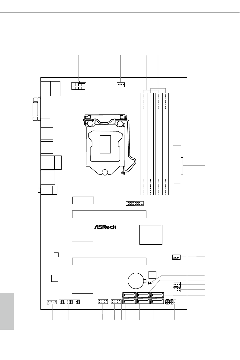
1.3 Motherboard Layout
English
6 7

No. Description
1 ATX 12V Power Connector (ATX12V1)
2 CPU Fan Connector (CPU_FAN1)
3 2 x 288-pin DDR4 DIMM Slots (DDR4_A1, DDR4_B1)
4 2 x 288-pin DDR4 DIMM Slots (DDR4_A2, DDR4_B2)
5 ATX Power Connector (ATXPWR1)
6 USB 3.0 Header (USB3_4_5)
7 Chassis Fan Connector (CHA_FAN1)
8 Clear CMOS Jumper (CLRMOS1)
9 SATA3 Connector (SATA3_2)
10 Chassis Fan Connector (CHA_FAN2)
11 Power LED and Speaker Header (SPK_PLED1)
12 SATA3 Connector (SATA3_0)
13 System Panel Header (PANEL1)
14 SATA3 Connector (SATA3_1)
15 SATA3 Connector (SATA3_3)
16 SATA3 Connector (SATA3_5)
17 SATA 3 C onnector (SATA3_4)
18 USB 2.0 Header (USB2_3)
19 USB 2.0 Header (USB4_5)
20 TPM Header (TPMS1)
21 Front Panel Audio Header (HD_AUDIO1)
Z170A-X1/3.1
English
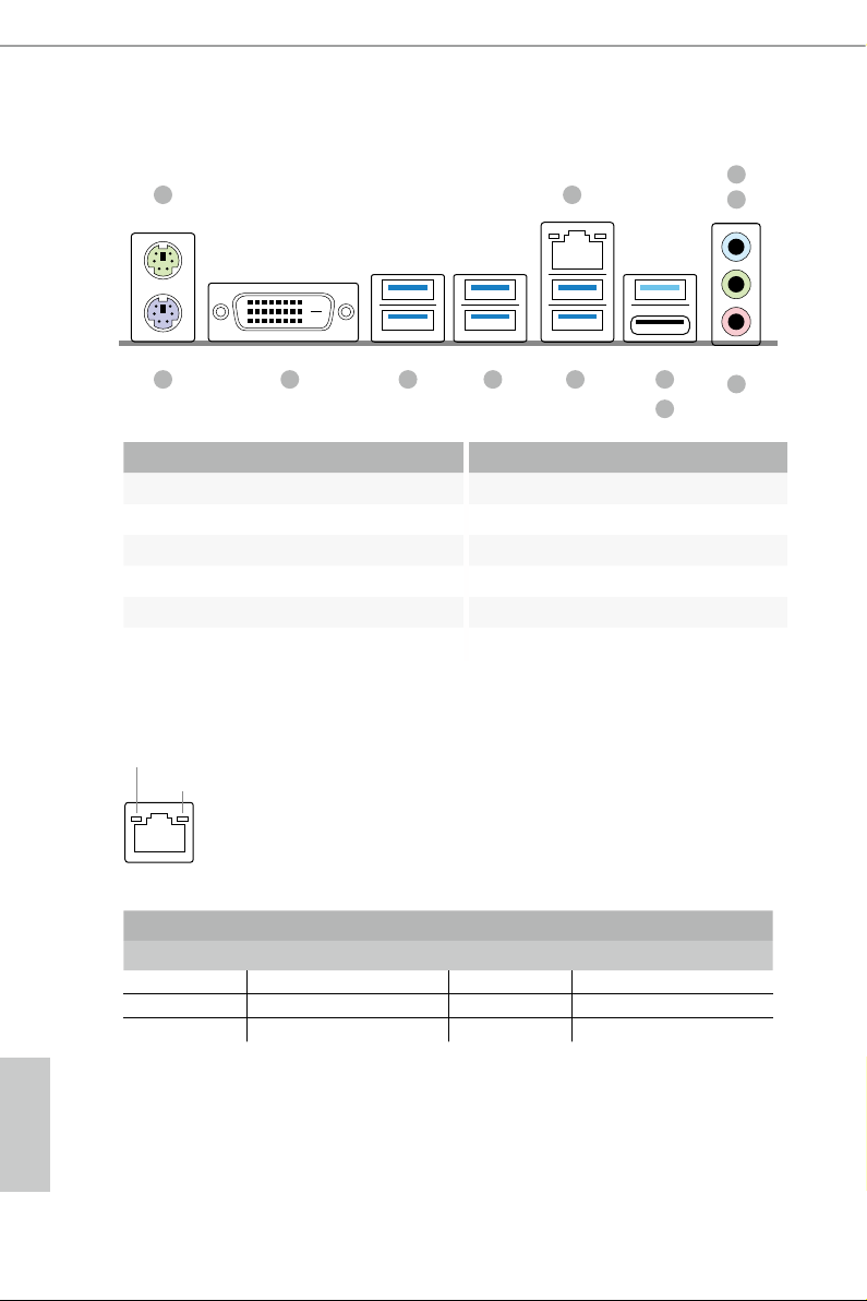
1.4 I/O Panel
1
2
4
3
12 6
891011
5
7
No. Description No. Description
1 PS/2 Mouse Port 7 USB 3.1 Type-C Port (USB31_TC_1)
2 LAN RJ-45 Port* 8 USB 3.0 Ports (USB_01)
3 Line In (Light Blue) 9 USB 3.0 Ports (USB3_23)
4 Front Speaker (Lime)** 10 USB 3.0 Ports (USB3_01)
5 Microphone (Pink) 11 DVI-D Port
6 USB 3.1 Type-A Port (USB31_TA_1) 12 PS/2 Keyboard Port
* ere are two LEDs on the LAN port. Please refer to the table below for the LAN port LED indications.
ACT/LINK LED
SPEED LED
LAN Por t
Activity / Link LED Speed LED
Status Description Status Description
O No Link O 10Mbps connection
Blinking Data Activity Orange 100Mbps connection
On Link Green 1Gbps connection
English
8 9
Z170A-X1/3.1
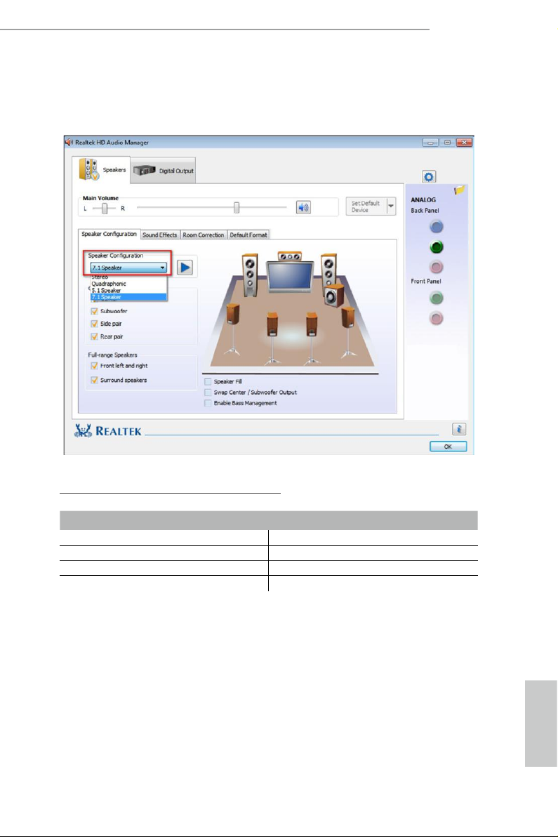
** To congure 7.1 CH HD Audio, it i s required to use an HD front panel audio module and enable the multichannel audio feature through the audio driver.
Please set Speaker Conguration to “7.1 Speaker”in the Realtek HD Audio Manager.
Function of the Audio Ports in 7.1-channel Conguration:
Port Function
Light Blue (Rear panel) Rear Speaker Out
Lime (Rear panel) Front Speaker Out
Pink (Rear panel) Central /Subwoofer Speaker Out
Lime (Front panel) Side Speaker Out
English

Chapter 2 Installation
is is an ATX form factor motherboard. Before you install the motherboard, study
the conguration of your chassis to ensure that the motherboard ts into it.
Pre-installation Precautions
Take note of the following precautions before you install motherboard components
or change any motherboard settings.
Make sure to unplug the power cord before installing or removing the motherboard
•
components. Failure to do so may cause physical injuries and damages to motherboard
components.
In order to avoid damage from static electricity to the motherboard’s components,
•
NEVER place your motherboard directly on a carpet. Also remember to use a grounded
wrist strap or touch a safety grounded object before you handle the components.
Hold components by the edges and do not touch the ICs.
•
Whenever you uninstall any components, place them on a grounded anti-static pad or
•
in the bag that comes with the components.
When placing screws to secure the motherboard to the chassis, please do not over-
•
tighten the screws! Doing so may damage the motherboard.
English
10 11
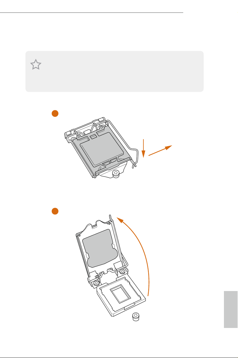
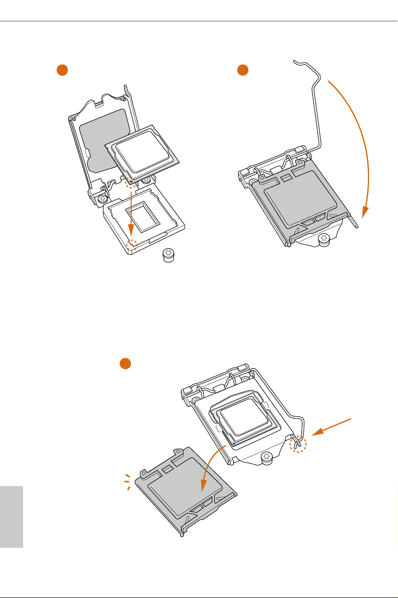
2.1 Installing the CPU
1. Before you insert the 1151-Pin CPU into the socket, please check if the P nP cap is on the
socket, if the CPU surface is unclean, or if there are any bent pins in the sock et. Do not
force to in sert the CPU into the socket if above situation is found . Otherwise, the CPU
will be seriously damaged.
2. Unplug all power c ables before in stalling the CPU.
1
Z170A-X1/3.1
A
B
2
English
3
4
5
English
12 13

Please save and replace the cover if the processor i s removed. e cover must be placed if
you wish to return the motherboard for aer service.
Z170A-X1/3.1
English
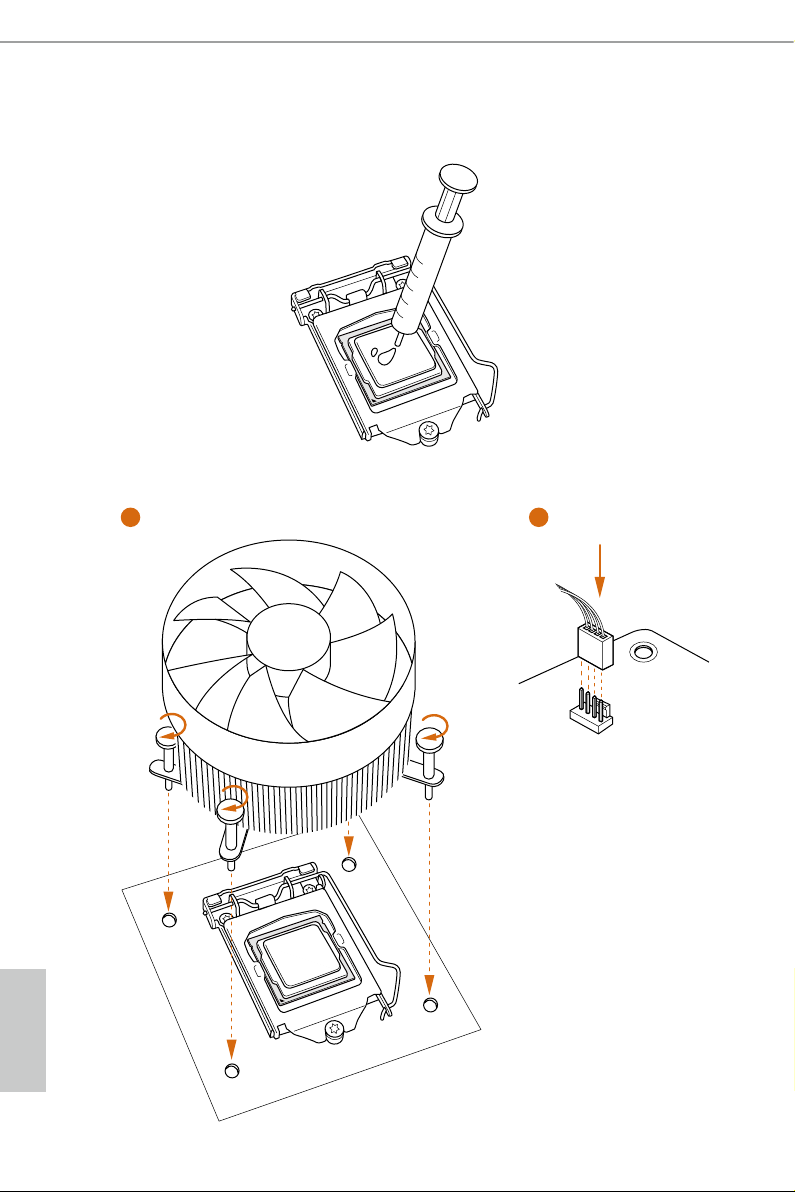
2.2 Installing the CPU Fan and Heatsink
1 2
FAN
CPU_
English
14 15
2.3 Installing Memory Modules (DIMM)
is motherboard provides four 288-pin DDR4 (Double Data Rate 4) DIMM slots,
and supports Dual Channel Memory Technology.
1. For dual channel cong uration , you always need to in stall identical (the same b rand,
speed , size and chip-type) DDR4 DIMM pairs.
2. It is unable to activate Dual Channel Memor y Te chnology with only one or three memory
module installed.
3. It is not allowed to install a DDR, DDR2 or DDR3 memory module into a DDR4 sl ot;
otherwise , this motherboard and DIM M may be damaged.
Dual Channel Memory Conguration
Priority DDR4_A1 DDR4_A2 DDR4_B1 DDR4_B2
1 Populated Populated
2 Populated Populated
3 Populated Populated Populated Populated
Z170A-X1/3.1
e DIMM only ts in one correct orie ntation. It will cause permanent dam age to the
motherboard and the DIMM if you force the DIMM into the slot at incorrect orientation.
English
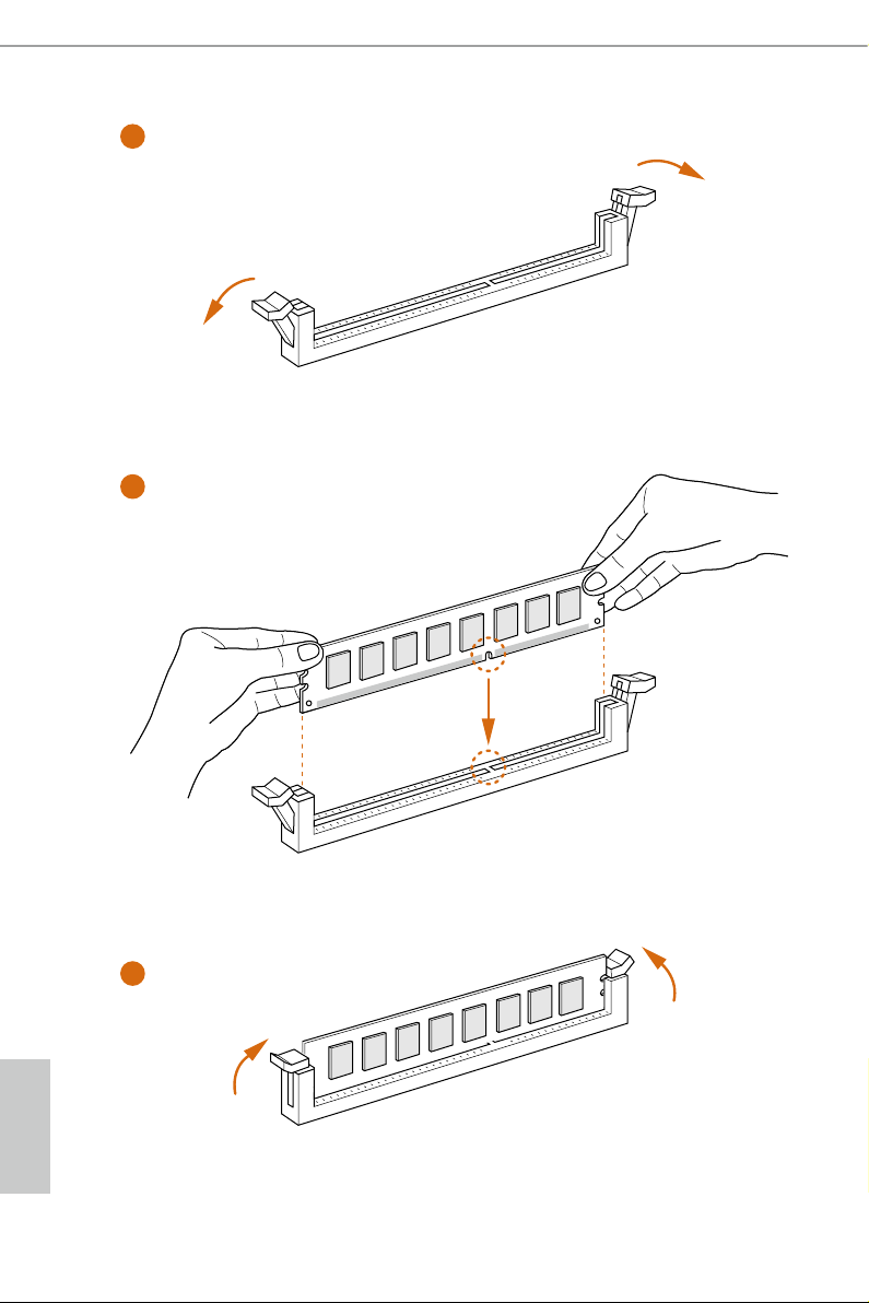
1
2
3
English
16 17

2.4 Expansion Slots (PCI Express Slots)
ere are 5 PCI Express slots on the motherboard.
Before installing an ex pansion card, please make sure that the power supply is switched o
or the power cord is unplug ged. Pl ease re ad the documentation of the expansion card and
make necessary hardware settings for the card before you start the installation.
PCIe slots:
PCIE1 (PCIe 3.0 x1 slot) is used for PCI Express x1 lane width cards.
PCIE2 (PCIe 3.0 x16 slot) is used for PCI Express x16 lane width graphics cards.
PCIE3 (PCIe 3.0 x1 slot) is used for PCI Express x1 lane width cards.
PCIE4 (PCIe 3.0 x16 slot) is used for PCI Express x4 lane width graphics cards.
PCIE5 (PCIe 3.0 x1 slot) is used for PCI Express x1 lane width cards.
PCIe Slot Congurations
PCIE2 PCIE4
Z170A-X1/3.1
Single Graphics Card x16 N/A
Two Graphics Cards in
CrossFireXTM Mode
For a better thermal environment, please connect a chassis fan to the motherboard’s chassis
fan connector (CHA _FAN1 or CH A_FAN2) when using multiple graphics card s.
x16 x4
English
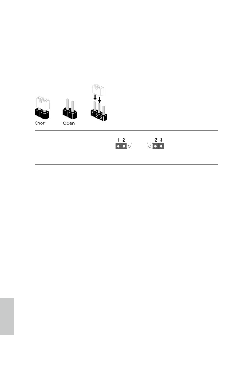
2.5 Jumpers Setup
e illustration shows how jumpers are setup. When the jumper cap is placed on
the pins, the jumper is “Short”. If no jumper cap is placed on the pins, the jumper
is “Open”. e illustration shows a 3-pin jumper whose pin1 and pin2 are “Short”
when a jumper cap is placed on these 2 pins.
Clear CMOS Jumper
(CLRMO S1)
(see p.6, No. 8)
CLRMOS1 allows you to clear the data in CMOS. To clear and reset the system
parameters to default setup, please turn o the computer and unplug the power
cord from the power supply. Aer waiting for 15 seconds, use a jumper cap to
short pin2 and pin3 on CLRMOS1 for 5 seconds. However, please do not clear the
CMOS right aer you update the BIOS. If you need to clear the CMOS when you
just nish updating the BIOS, you must boot up the system rst, and then shut it
down before you do the clear-CMOS action. Please be noted that the password,
date, time, and user default prole will be cleared only if the CMOS battery is
removed.
Clear CMOSDefault
English
18 19
2.6 Onboard Headers and Connectors
1
Onboard headers and connectors are NOT jump ers. Do NOT place jumper caps over these
heade rs and connectors. Placing jumper caps over the headers and connectors will cause
permanent damage to the motherboard.
Z170A-X1/3.1
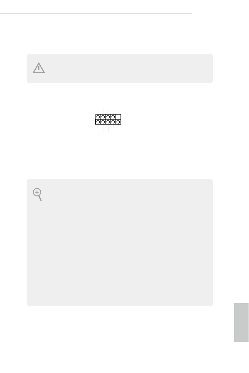
System Panel Header
(9-pi n PANEL1)
(see p.6, No. 13)
PWRBTN (Power Switch):
Connec t to the power switch on the ch assi s front panel. You may congure the way to tur n
o your system using the power switch.
RESET (Reset Switch):
Connec t to the reset switch on the chassi s front panel. Press the reset sw itch to restart the
computer if the computer f reezes and fails to per form a normal restar t.
PLED (Syste m Power LED):
Connec t to the power status indicator on the chas sis front panel. e LED i s on when the
system is operating. e LED keeps blinking when the system is in S1/S3 sleep state. e
LED is o when the system is in S4 slee p state or powered o (S5).
HDLED (Ha rd Drive Activity LED):
Connec t to the hard drive ac tivity LED on the chassis front panel. e LED is on when the
hard drive is reading or wr iting data.
e front panel de sign may dier by chassis. A front panel module mainly consists of powe r
switch, reset switch , power LED, hard dr ive activity LED, speaker and etc. When connecting your ch assi s front panel module to thi s header, make sure the wire a ssignments and the
pin assignments are matched correctly.
PLED+
PLED-
HDLED-
HDLED+
PWRBTN#
GND
RESET#
GND
GND
Connect the power
switch, reset switch and
system status indicator on
the chassis to this header
according to the pin
assignments below. Note
the positive and negative
pins before connecting
the cables.
English
Power LED and Speaker
1
+5V
DUMMY
PLED+
PLED+
PLED-
DUMMY
SPEAKER
DUMMY
GND
GND
P+
P-
USB_PWR
P+
P-
USB_PWR
1
1
ID
IntA_P_D+
Header
(7-pin SPK_PLED1)
(see p.6, No. 11)
Please connect the
chassis power LED and
the chassis speaker to this
header.
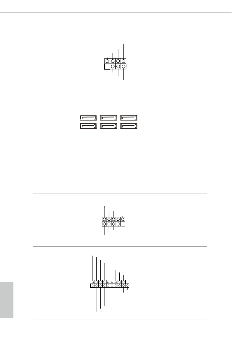
Serial ATA3 Connectors
(SATA3_0:
see p.6, No. 12)
(SATA3_1:
see p.6, No. 14)
(SATA3_ 2:
see p.6, No. 9)
(SATA3_ 3:
see p.6, No. 15)
SATA3_2SATA3_4
SATA3_3SATA3_5
SATA3_0
SATA3_1
ese six SATA3
connectors support SATA
data cables for internal
storage devices with up
to 6.0 Gb/s data transfer
rate. To minimize the
boot time, use Intel® Z170
SATA ports (SATA3_0)
for your bootable devices.
(SATA3_4:
see p.6, No. 17)
(SATA3_ 5:
see p.6, No. 16)
USB 2.0 Headers
(9-pin USB2_3)
(see p.6, No. 18)
(9-pin USB4_5)
ere are two headers
on this motherboard.
Each USB 2.0 header can
support two ports.
(see p.6, No. 19)
USB 3.0 Header
(19-pin USB3_4_ 5)
(see p.6, No. 6)
English
20 21
IntA_P_D-
GND
IntA_P_D-
IntA_P_D+
IntA_P_SSTX+
IntA_P_SSTX-
GND
IntA_P_SSTX-
IntA_P_SSTX+
GND
IntA_P_SSRX+
IntA_P_SSRX-
Vbus
IntA_P_SSRX-
IntA_P_SSRX+
GND
Besides si x USB 3.0 ports
on the I/O panel, there
is one header on this
motherboard. Each USB
3.0 header can support
two ports.
Vbus

Z170A-X1/3.1
J_SENSE
OUT2_L
1
MIC_RET
PRESENCE#
GND
OUT2_R
MIC2_R
MIC2_L
OUT_RET
GND
OL
FAN_SPEED_CONTROL
4 3 2 1
Front Panel Audio Header
(9-pin HD_ AUDIO1)
(see p.6, No. 21)
1. High Denition Audio support s Jack Sensing, but the panel wire on the cha ssis must sup port HDA to function correctly. Ple ase fol low the instructions in our manual and chassis
manual to install your system.
2. If you use an AC’97 audio panel , please install it to th e front panel audio header by the
steps below:
A. Connect Mic_IN (MIC) to MIC2_ L.
B. Conne ct Audio_R (RIN) to OUT2_R and Audio_ L (LIN) to OUT2_ L.
C. Connect Ground (GND) to Ground (GND).
D. MIC_ RET and OUT_RET are for the HD audio panel only. You don’t ne ed to conn ect
them for the AC’97 audio panel .
E. To activate the front mic, go to the “FrontMic” Tab in the Realtek Control panel and
adjust “Recording Volume”.
Chassis Fan Connectors
(4-pin CHA_FAN1)
(see p.6, No. 7)
FAN_VOLTAGE
CHA_FAN_SPEED
FAN_SPEED_CONTR
(4-pin CHA_FAN2)
is header is for
connecting audio devices
to the front audio panel.
Please connect fan cables
to the fan connectors and
match the black wire to
the ground pin.
(see p.6, No. 10)
CPU Fan Connectors
(4-pin CPU_FAN1)
(see p.6, No. 2)
ATX Power Connector
(24-p i n ATX PWR1)
(see p.6, No. 8)
CPU_F
12
1
GND
FAN_VOLTAGE
AN_SPEED
24
13
is motherboard pro-
vides a 4-Pin CPU fan
(Quiet Fan) connector.
If you plan to connect a
3-Pin CPU fan, please
connect it to Pin 1-3.
is motherboard pro-
vides a 24-pin ATX power
connector. To use a 20-pin
ATX power supply, please
plug it along Pin 1 and Pin
13.
English

ATX 12V Power
5
1
8
#
Connector
(8-pin ATX12V1)
(see p.6, No. 1)
is motherboard pro-
vides an 8-pin ATX 12V
power connector. To use a
4-pin ATX power supply,
please plug it along Pin 1
and Pin 5.
TPM Header
(17-pi n TP MS1)
(see p.6, No. 20)
GN D
LAD 0
+3 V
+3V S B
D
GN
GN D
LAD 1
SER IRQ #
S_P WRD WN #
PC ICL K
LAD 3
PC IRS T
FRA M E
GN D
LAD 2
Platform Module (TPM) system,
1
which can securely store keys,
digital certicates, passwords,
and data. A TPM system also
helps enhance network security,
SMB _CL K_MA IN
SMB _DA TA_M AIN
protects digital identities, and
ensures platform integrity.
is connector supports Trusted
English
22 23

2.7 CrossFireXTM and Quad CrossFireXTM Operation Guide
is motherboard supports CrossFireXTM and Quad CrossFireXTM that allows you
to install up to three identical PCI Express x16 graphics cards.
1. You should only use identical CrossFireXTM-ready g raphics cards that are AM D
certied.
2. Make sure that your g raphics card driver supports A MD CrossFireXTM technology.
Download the drivers from the A MD’s website: www.amd.com
3. Make sure that your power sup ply unit (PSU) can prov ide at le ast the minimum
power your syste m require s. It is recommended to use a AMD certied PSU. Plea se
refer to the AMD’s website for d etail s.
4. If you pair a 12-pipe Cros sFireXTM Edition card with a 16-pipe card, both cards will
operate a s 12-pipe cards while in CrossFireXTM mode.
5. Dierent CrossFireXTM cards may require dierent method s to enable CrossFi-
reXTM. Please refer to A MD graphics card manuals for de tailed installation guide.
2.7.1 Installing Two CrossFireXTM-Ready Graphics Cards
Step 1
Insert one graphics card into PCIE2 slot
and the other graphics card to PCIE4 slot.
Make sure that the cards are properly
seated on the slots.
Z170A-X1/3.1
CrossFire Bridge
Step 2
Connect two graphics cards by installing
a CrossFire Bridge on the CrossFire Bridge
Interconnects on the top of the graphics
cards. (e CrossFire Bridge is provided
with the graphics card you purchase, not
bundled with this motherboard. Please
refer to your graphics card vendor for
deta ils .)
English

Step 3
Connect a VGA cable or a DVI cable to the
monitor connector or the DVI connec-
tor of the graphics card that is inserted to
PCIE2 slot.
English
24 25

2.7.2 Driver Installation and Setup
Step 1
Power on your computer and boot into OS.
Step 2
Remove the AMD drivers if you have any VGA drivers installed in your system.
e Catalyst Unins talle r is an optional do wnload. We recommend us ing this utility to uninstall any previously installed Catalyst drivers prior to installation. Plea se check AMD’s
website for AMD driver updates .
Step 3
Install the required drivers and CATALYST Control Center then restart your
computer. Please check AMD’s website for details.
Step 4
Double-click the AMD Catalyst Control
AMD Catalyst Control Center
Center icon in the Windows® sy stem tray.
Z170A-X1/3.1
Step 5
In the le pane, click Performance and
then AMD CrossFireXTM. en select
Enable AMD CrossFireX and click Apply.
Select the GPU number according to your
graphics card and click Apply.
English

Chapter 3 Software and Utilities Operation
3.1 Installing Drivers
e Support CD that comes with the motherboard contains necessary drivers and
useful utilities that enhance the motherboard’s features.
Running The Support CD
To begin using the support CD, insert the CD into your CD-ROM drive. e CD
automatically displays the Main Menu if “AUTORUN” is enabled in your computer.
If the Main Menu does not appear automatically, locate and double click on the le
“ASRSETUP.EXE” in the Support CD to display the menu.
Drivers Menu
e drivers compatible to your system will be auto-detected and listed on the
support CD driver page. Please click Install All or follow the order from top to
bottom to install those required drivers. erefore, the drivers you install can work
properly.
Utilities Menu
e Utilities Menu shows the application soware that the motherboard supports.
Click on a specic item then follow the installation wizard to install it.
To improve Windows 7 compatibility, please download and install the following hot x
provided by Microso.
“KB2720599”: http://support.microso.com/kb/2720599/en-us
English
26 27

3.2 A-Tuning
A-Tuning is ASRock’s multi purpose soware suite with a new interface, more new
features and improved utilities.
3.2.1 Installing A-Tuning
A-Tu ni n g can be downloaded from ASRock Live Update & APP Shop. Aer the
installation, you will nd the icon “A-Tu n i ng“ on your desktop. Double-click the
“A-Tu ni n g“ icon, A-Tu n i n g main menu will pop up.
3.2.2 Using A-Tuning
ere are six sections in A-Tuning main menu: Operation Mode, OC Tweaker,
System Info, FAN-Tastic Tuning, Tech Service and Settings.
Operation Mode
Choose an operation mode for your computer.
Z170A-X1/3.1
English

OC Tw eaker
Congurations for overclocking the system.
System Info
View information about the system.
*e System Browser tab may not appear for certain models.
English
28 29

Z170A-X1/3.1
FAN-Tastic Tuning
Congure up to ve dierent fan speeds using the graph. e fans will automatically shi
to the next speed level when the assigned temperature is met.
Tech Ser vice
Contact Tech Service if you have problems with your computer. Please leave your
contact information along with details of the problem.
English

Settings
Congure ASRock A-Tuning. Click to select "Auto run at Windows Startup" if you
want A-Tuning to be launched when you start up the Windows operating system.
English
30 PB

3.3 ASRock Live Update & APP Shop
e ASRock Live Update & APP Shop is an online store for purchasing and
downloading soware applications for your ASRock computer. You can quickly and
easily install various apps and support utilities, such as USB Key, XFast LAN, XFast
RAM and more. With ASRock APP Shop, you can optimize your system and keep
your motherboard up to date simply with a few clicks.
Double-click on your desktop to access ASRock Live Update & APP Shop
utility.
*You need to be connected to the Internet to download apps f rom the ASRock Live Update & APP Shop.
3.3.1 UI Overview
Category Panel
Hot News
Z170A-X1/3.1
Information Panel
Category Panel: e category panel contains several category tabs or buttons that
when selected the information panel below displays the relative information.
Information Panel: e information panel in the center displays data about the
currently selected category and allows users to perform job-related tasks.
Hot News: e hot news section displays the various latest news. Click on the image
to visit the website of the selected news and know more.
English

3.3.2 Apps
When the "Apps" tab is selected, you will see all the available apps on screen for you
to download.
Installing an App
Step 1
Find the app you want to install.
e most recommended app appears on the le side of the screen. e other various
apps are shown on the right. Please scroll up and down to see more apps listed.
You can check the price of the app and whether you have already intalled it or not.
- e red icon displays the price or "Free" if the app is free of charge.
- e green "Installed" icon means the app is installed on your computer.
Step 2
Click on the app icon to see more details about the selected app.
English
32 33

Step 3
If you want to install the app, click on the red icon to start downloading.
Step 4
When installation completes, you can nd the green "Installed " icon appears on the
upper right corner.
Z170A-X1/3.1
To uninstall it, simply click on the trash can icon .
*e trash icon may not appear for certain apps.
English

Upgrading an App
You can only upgrade the apps you have already installed. When there is an
available new version for your app, you will nd the mark of "New Version"
appears below the installed app icon.
Step 1
Click on the app icon to see more details.
Step 2
Click on the yellow icon to start upgrading.
English
34 35

3.3.3 BIOS & Drivers
Installing BIOS or Drivers
When the "BIOS & Drivers" tab is selected, you will see a list of recommended or
critical updates for the BIOS or drivers. Please update them all soon.
Z170A-X1/3.1
Step 1
Please check the item information before update. Click on to see more details.
Step 2
Click to select one or more items you want to update.
Step 3
Click Update to start the update process.
English

3.3.4 Setting
In the "Setting" page, you can change the language, select the server location, and
determine if you want to automatically run the ASRock Live Update & APP Shop
on Windows startup.
English
36 37

Z170A-X1/3.1
3.4 Creating Windows® 7 Installation Disk with USB 3.0 Drivers Packed
e USB 3.0 ports on your motherboard require the USB 3.0 drivers to function
properly. Due to the Windows® 7 installation disk does not include the USB 3.0
drivers, please create a Windows® 7 installation disk with the Intel® USB 3.0
eXtensible Host Controller (xHCI) drivers packed into the ISO le of your own.
Requirements
A program that can create and modify ISO les, such as UltraISO
•
Windows® 7 installation disk
•
USB 3.0 drivers (included in the ASRock Support CD)
•
Windows® PC
•
Instructions
Step 1
Create a new folder under C:\ on your computer. Here we name the folder "asrock" as an
example.
Step 2
Create another two subfolders under the "asrock" folder. Name the subfolder "mount" and
"usb3" as examples.
Step 3
Insert Windows® 7 installation disk in your CD drive.
Step 4
Copy "boot.wim" and "install.wim" les from the "Sources" folder in the Windows® 7
installation disk to the "asrock" folder created in Step 1.
Step 5
Insert the ASRock Support CD in your CD drive.
Step 6
Go to folder "Drivers" and then nd the "Intel USB3.0 Driver" folder.
English

Step 7
Make sure the Windows 7 you are going to install is the 32-bit version or the 64-bit version.
For 64-bit Windows 7:
Copy all 12 les under the folders "HCSwitch" (x64) and "Win7" (x64) in the "Drivers" to
the subfolder "usb3" created in Step 2.
For 32-bit Windows 7:
Copy all 12 les under the folders "HCSwitch" (x86) and "Win7" (x86) in the "Drivers" to
the subfolder "usb3" created in Step 2.
Step 8
Open the "Start" menu and type "command" or "cmd" to launch the command prompt as
an administrator.
English
38 39

Z170A-X1/3.1
Step 9
Enter the folder created in Step 1, by inputting "cd.." and "cd (folder name)" commands.
Refer to the screenshot below.
"cd.." : go to the upper level
"cd (folder name)" : enter the assigned folder
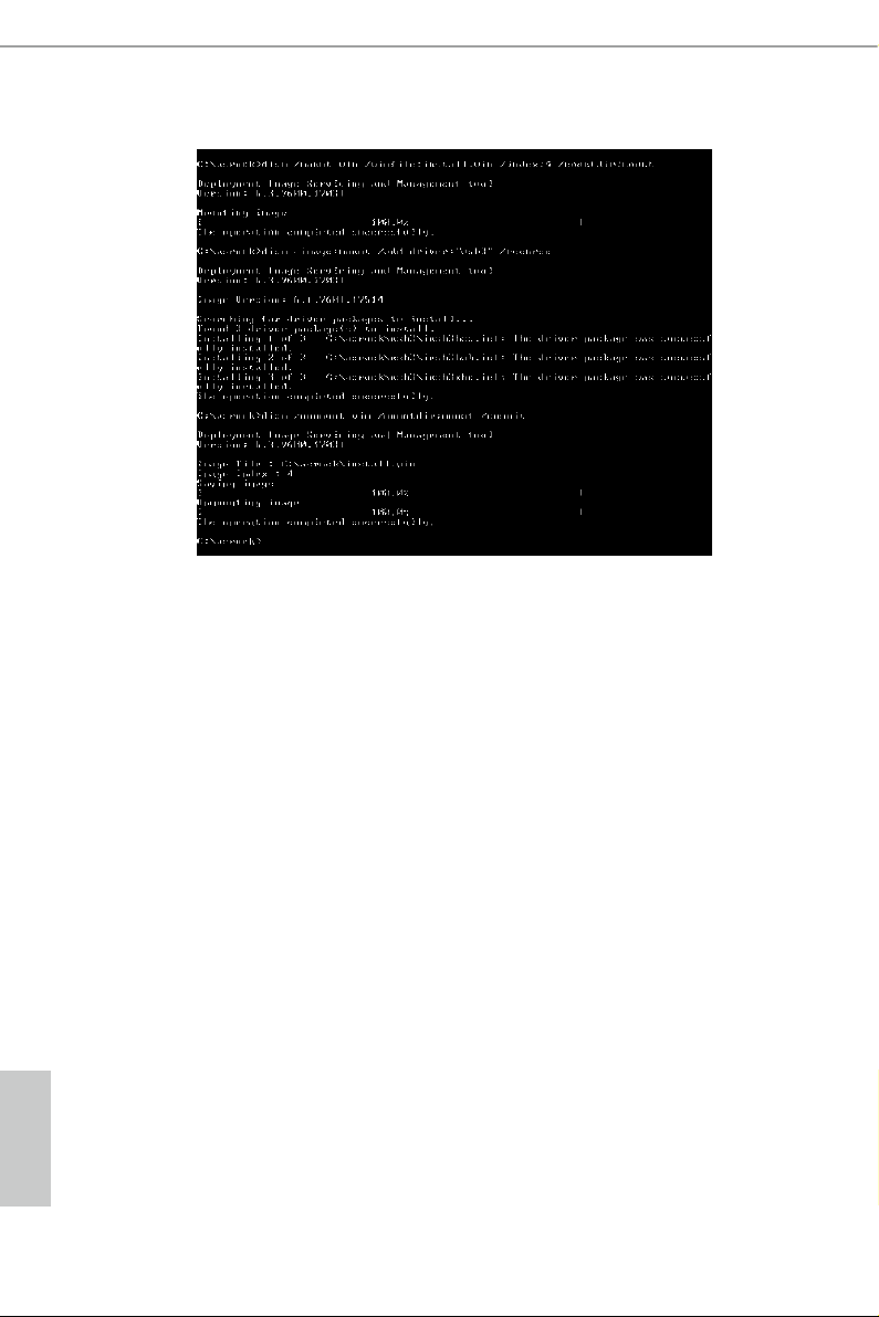
Ste p 10
To add USB 3.0 drivers into " boot.wim" in order to install Windows® 7 by ash3.0, please
input the following commands in order and wait until the each process completes.
dism /mount-wim /wimle:boot.wim /index:2 /mountdir:mount
dism /image:mount /add-driver:"usb3" /recurse
dism /unmount-wim /mountdir:mount /commit
Ste p 11
To add the drivers into the "insta ll.wim" image le, please input the following commands
in order and wait until the each process completes.
dism /mount-wim /wimle:install.wim /index:4 /mountdir:mount
dism /image:mount /add-driver:"usb3" /recurse
dism /unmount-wim /mountdir:mount /commit
English
English
In this step, please particularly pay attention to the Index number in the rst command.
Index represents the dierent versions of Windows® 7. Please check the followings for the
versions you use:
Index : 1 Windows 7 HOMEBASIC
Index : 2 Windows 7 HOMEPREMIUM
Index : 3 Windows 7 PROFESSIONAL
Index : 4 Windows 7 ULTIMATE
St ep 12
Use a program that can create and modify ISO les, such as UltraISO, to copy the modied
"boot.wim" and "install.win" les to the same directory in the Windows® 7 installation disk
and cover the original les. (We recommend backing up the original version just in case.)
Save as a new ISO le, and then burn the CD or USB which can be used to install.
40 PB

Chapter 4 UEFI SETUP UTILITY
4.1 Introduction
is section explains how to use the UEFI SETUP UTILITY to congure your
system. You may run the UEFI SETUP UTILITY by pressing <F2> or <Del> right
aer you power on the computer, other wise, the Power-On-Self-Test (POST) will
continue with its test routines. If you wish to enter the UEFI SETUP UTILITY aer
POST, restart the system by pressing <Ctl> + <Alt> + <Delete>, or by pressing the
reset button on the system chassis. You may also restart by turning the system o
and then back on.
Becau se the UEFI soware is constantly being upd ated, the following UEFI setup screens
and descriptions are for reference pur pose only, and they may not exactly match what you
see on your screen.
Z170A-X1/3.1
English

4.2 EZ Mode
e EZ Mode screen appears when you enter the BIOS setup program by default. EZ
mode is a dashboard which contains multiple readings of the system’s current status.
You can check the most crucial information of your system, such as CPU speed,
DRAM frequency, SATA information, fan speed, etc.
Press <F6> or click the "Advanced Mode" button at the upper right corner of the
screen to switch to "Advanced Mode" for more options.
No. Function
Help
1
Load UEFI Defaults
2
Save Changes and Exit
3
Discard Changes
4
Change Language
5
Switch to Advanced Mode
English
6
42 43

4.3 Advanced Mode
e Advanced Mode provides more options to congure the BIOS settings. Refer to
the following sections for the detailed congurations.
To access the EZ Mode, press <F6> or click the "EZ Mode" button at the upper right
corner of the screen.
4.3.1 UEFI Menu Bar
e top of the screen has a menu bar with the following selections:
Z170A-X1/3.1
Main
OC Tweaker
Advanced
Tool
H/W Monitor
Boot
Security
Exit
For setting system time/date information
For overclocking congurations
For advanced system congurations
Useful tools
Displays current hardware status
For conguring boot settings and boot priority
For security settings
Exit the current screen or the UEFI Setup Utility
English

4.3.2 Navigation Keys
Use < > key or < > key to choose among the selections on the menu bar, and
use < > key or < > key to move the cursor up or down to select items, then
press <Enter> to get into the sub screen. You can also use the mouse to click your
required item.
Please check the following table for the descriptions of each navigation key.
Navigation Key(s) Description
+ / -
<Tab>
<PGUP>
<PGDN>
<HOME>
<END>
<F1>
<F5>
<F6>
<F7>
<F9>
<F10>
<F12>
To change option for the selected items
Switch to next function
Go to the previous page
Go to the next page
Go to the top of the screen
Go to the bottom of the screen
To display the General Help Screen
Add / Remove Favorite
Switch to the EZ mode
Discard changes and exit the SETUP UTILITY
Load optimal default values for all the settings
Save changes and exit the SETUP UTILITY
Print screen
<ESC>
Jump to the Exit Screen or exit the current screen
English
44 45

4.4 Main Screen
When you enter the UEFI SETUP UTILITY, the Main screen will appear and
display the system overview.
Favorite
Display your collection of BIOS items. Press F5 to add/remove your favorite items.
Z170A-X1/3.1
English
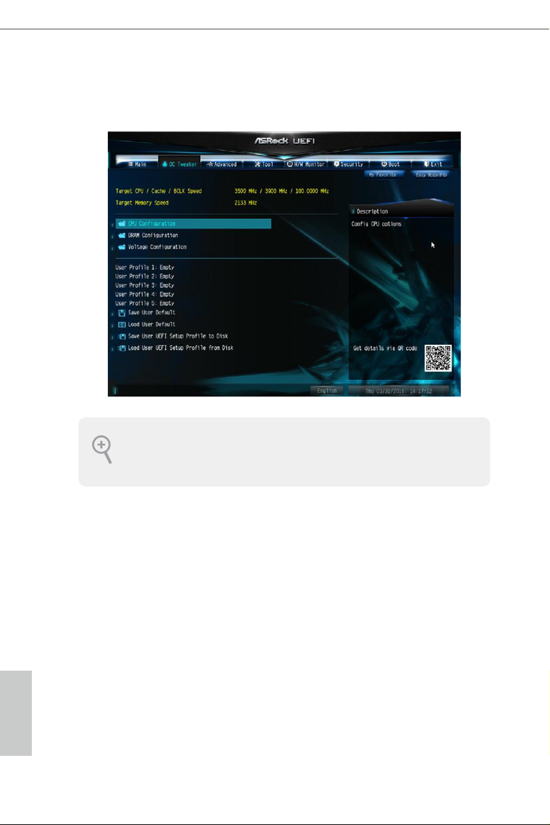
4.5 OC Tweaker Screen
In the OC Tweaker screen, you can set up overclocking features.
Becau se the UEFI soware is constantly being upd ated, the following UEFI setup screens
and descriptions are for reference pur pose only, and they may not exactly match what you
see on your screen.
Advanced Turbo
You can use this option to increase your system performance. is option appears only
when your CPU supports this function. is option appears only when you adopt K-Series
CPU.
Load Optimized CPU OC Setting
You can use this option to load optimized CPU overclocking setting. Please note that
overclocking may cause damage to your CPU and motherboard. It should be done at your
own risk and expense.
English
Load Optimized GPU OC Setting
You can use this option to load optimized GPU overclocking setting. Please note that
overclocking may cause damage to your GPU and motherboard. It should be done at your
own risk and expense. is option appears only when you adopt K-Series CPU.
46 47

CPU Conguration
Multi Core Enhancement
Improve the system's performance by forcing the CPU to perform the highest
frequency on all CPU cores simultaneously. Disable to reduce power consumption .
CPU Ratio
e CPU speed is determined by the CPU Ratio multiplied with the BCLK.
Increasing the CPU Ratio will increase the internal CPU clock speed without
aecting the clock speed of other components.
CPU Cache Ratio
e CPU Internal Bus Speed Ratio. e maximum should be the same as the CPU
Ratio.
Minimum CPU Cache Ratio
Set the minimum CPU Internal Bus Speed Ratio.
BCLK Frequency
e CPU speed is determined by the CPU Ratio multiplied with the BCLK.
Increasing the BCLK will increase the internal CPU clock speed but also aect the
clock speed of other components.
Z170A-X1/3.1
BCLK Spread Spectrum
Enable BCLK Spread Spectrum to reduce electromagnetic interference for passing
EMI tests. Disable to achieve higher clock speeds when overclocking.
Boot Performance Mode
Select the performance state that the BIOS will set before OS hando.
Reliability Stress Restrictor
Disable or Enable Reliability Stress Restrictor feature.
FCLK Frequency
Congure the FCLK Frequency.
Intel SpeedStep Technology
Intel SpeedStep technology allows processors to switch between multiple frequen-
cies and voltage points for better power saving and heat dissipation.
English

Intel Turbo Boost Technology
Intel Turbo Boost Technolog y enables the processor to run above its base operating
frequency when the operating system requests the highest performance state.
Long Duration Power Limit
Congure Package Power Limit 1 in watts. When the limit is exceeded, the CPU
ratio will be lowered aer a period of time. A lower limit can protect the CPU and
save power, while a higher limit may improve performance.
Long Duration Maintained
Congure the period of time until the CPU ratio is lowered when the Long
Duration Power Limit is exceeded.
Short Duration Power Limit
Congure Package Power Limit 2 in watts. When the limit is exceeded, the CPU
ratio will be lowered immediately. A lower limit can protect the CPU and save
power, while a higher limit may improve performance.
System Agent Current Limit
Congure the current limit of the system agent. A lower limit can protect the CPU
and save power, while a higher limit may improve performance.
CPU Core Current Limit
Congure the current limit of the CPU core. A lower limit can protect the CPU and
save power, while a higher limit may improve performance.
GT Slice Current Limit
Congure the current limit of the GT slice. A lower limit can protect the CPU and
save power, while a higher limit may improve performance.
GT Frequency
Congure the frequency of the integrated GPU.
DRAM Conguration
DRAM Information
English
Fine tune the DRAM settings by leaving marks in checkboxes. Click OK to conrm and
apply your new settings.
48 49

Z170A-X1/3.1
DRAM Timing Conguration
Load XMP Setting
Load XMP settings to overclock the memory and perform beyond standard specications.
DRAM Reference Clock
Select Auto for optimized settings.
DRAM Frequency
If [Auto] is selected, the motherboard will detect the memory module(s) inserted
and assign the appropriate frequency automatically.
Primary Timing
CAS# Latency (tCL)
e time between sending a column address to the memory and the beginning of the data
in response.
RAS# to CAS# Delay and Row Precharge (tRCDtRP)
RAS# to CAS# Delay : e number of clock cycles required between the opening of
a row of memory and accessing columns within it.
Row Precharge: e number of clock cycles required between the issuing of the
precharge command and opening the next row.
RAS# Active Time (tRAS)
e number of clock cycles required between a bank active command and issuing the
precharge command.
Command Rate (CR)
e delay between when a memor y chip is selected and when the rst active command can
be issued.
Secondary Timing
Write Recovery Time (tWR)
e amount of delay that must elapse aer the completion of a valid write operation,
before an active bank can be precharged.
Refresh Cycle Time (tRFC)
e number of clocks from a Refresh command until the rst Activate command to
the same rank.
English

RAS to RAS Delay (tRRD_L)
e number of clocks between two rows activated in dierent banks of the same
rank.
RAS to RAS Delay (tRRD_S)
e number of clocks between two rows activated in dierent banks of the same
rank.
Write to Read Delay (tWTR_L)
e number of clocks between the last valid write operation and the next read command to
the same interna l bank.
Write to Read Delay (tWTR_S)
e number of clocks between the last valid write operation and the next read command to
the same interna l bank.
Read to Precharge (tRTP)
e number of clocks that are inserted between a read command to a row pre-
charge command to the same rank.
Four Activate Window (tFAW)
e time window in which four activates are allowed the same rank.
CAS Write Latency (tCWL)
Congure CAS Write Latency.
Third Timing
tREFI
Congure refresh cycles at an average periodic interval.
tCKE
Congure the period of time the DDR4 initiates a minimum of one refresh
command internally once it enters Self-Refresh mode.
tRDRD_sg
English
Congure between module read to read delay.
tRDRD_dg
Congure between module read to read delay.
50 51

tRDRD_dr
Congure between module read to read delay.
tRDRD_dd
Congure between module read to read delay.
tRDWR_sg
Congure between module read to write delay.
tRDWR_dg
Congure between module read to write delay.
tRDWR_dr
Congure between module read to write delay.
tRDWR_dd
Congure between module read to write delay.
tWRRD_sg
Congure between module write to read delay.
Z170A-X1/3.1
tWRRD_dg
Congure between module write to read delay.
tWRRD_dr
Congure between module write to read delay.
tWRRD_dd
Congure between module write to read delay.
tWRWR_sg
Congure between module write to write delay.
tWRWR_dg
Congure between module write to write delay.
tWRWR_dr
Congure between module write to write delay.
English

tWRWR_dd
Congure between module write to write delay.
RTL (CH A)
Congure round trip latency for channel A.
RTL (CH B)
Congure round trip latency for channel B.
IO-L (CH A)
Congure IO latency for channel A.
IO-L (CH B)
Congure IO latency for channel B.
Fourth Timing
twRPRE
Congure twR PRE.
Write_Early_ODT
Congure Write_Early_ODT.
tAONPD
Congure tAONPD.
tXP
Congure tXP.
tXPDLL
Congure tXPDLL.
tPRPDEN
Congure tPRPDEN.
tRDPDEN
English
Congure tRDPDEN.
twRPDEN
Congure twR PDEN.
52 53

OREF_RI
Congure OREF_RI.
tREFIx9
Congure tR EFIx9.
txSDLL
Congure txSDLL.
txs_oset
Congure txs_oset.
tZQOPER
Congure tZQOPER.
tMOD
Congure tMOD.
ZQCS_period
Congure ZQCS_period.
Z170A-X1/3.1
tZQCS
Congure tZQCS.
Advanced Setting
ODT WR (CH A)
Congure the memory on die termination resistors' WR for channel A.
ODT WR (CH B)
Congure the memory on die termination resistors' WR for channel B.
ODT PARK (CH A)
Congure the memory on die termination resistors' PARK for channel A.
ODT PARK (CH B)
Congure the memory on die termination resistors' PARK for channel B.
ODT NOM (CH A)
Use this to change ODT (CH A) Auto/Manual settings. e default is [Auto].
English

ODT NOM (CH B)
Use this to change ODT (CH B) Auto/Manual settings. e default is [Auto].
MRC Fast Boot
Enable Memory Fast Boot to skip DRAM memory training for booting faster.
Voltage Conguration
DRAM Voltage
Use this to congure DRAM Voltage. e default value is [Auto].
CPU Vcore Voltage
Congure the voltage for the CPU Vcore.
PCH +1.0 Voltage
Congure the chipset voltage.
VCC PLL Voltage
Congure the chipset voltage.
GT Voltage
Congure the voltage for the integrated GPU. .
VCCSA Voltage
Congure the voltage for the VCCSA.
Save User Default
Type a prole name and press enter to save your settings as user default.
Load User Default
Load previously saved user defaults.
English
54 55

4.6 Advanced Screen
In this section, you may set the congurations for the following items: CPU
Conguration, Chipset Conguration, Storage Conguration, ACPI Conguration,
USB Conguration and Trusted Computing.
Z170A-X1/3.1
Setting wrong values in this sec tion may cause the system to malfunction.
UEFI Conguration
UEFI Setup Style
Select the default mode when entering the UEFI setup utility.
Active Page on Entry
Select the default page when entering the UEFI setup utility.
Full HD UEFI
When [Auto] is selected, the resolution will be set to 1920 x 1080 if the monitor
supports Full HD resolution. If the monitor does not support Full HD resolution,
then the resolution will be set to 1024 x 768. When [Disable] is selected, the
resolution will be set to 1024 x 768 directly.
English

4.6.1 CPU Conguration
Active Processor Cores
Select the number of cores to enable in each processor package.
CPU C States Support
Enable CPU C States Support for power saving. It is recommended to keep C3, C6
and C7 all enabled for better power saving.
Enhanced Halt State (C1E)
Enable Enhanced Halt State (C1E) for lower power consumption.
CPU C3 State Support
Enable CPU C3 State Support for power saving.
CPU C6 State Support
Enable CPU C6 State Support for power saving.
CPU C7 State Support
English
Enable CPU C7 State Support for power saving.
Package C State Support
Enable CPU, PCIe, Memor y, Graphics C State Support for power saving.
56 57

CPU Thermal Throttling
Enable CPU internal thermal control mechanisms to keep the CPU from overheat-
ing.
No-Execute Memory Protection
Processors with No-Execution Memory Protection Technology may prevent certain
classes of malicious buer overow attacks.
Intel Virtualization Technology
Intel Virtualization Technology allows a platform to run multiple operating systems
and applications in independent partitions, so that one computer system can
function as multiple virtual systems.
Hardware Prefetcher
Automatically prefetch data and code for the processor. Enable for better
performance.
Adjacent Cache Line Prefetch
Automatically prefetch the subsequent cache line while retrieving the currently
requested cache line. Enable for better performance.
Z170A-X1/3.1
English

4.6.2 Chipset Conguration
Primary Graphics Adapter
Select a primary VGA.
Top of Lower usable DRAM
Set the maximum value of TOLUD. Set this item to Dynamic to allow TOLUD to
adjust automatically based on the largest MMIO length of the installed graphic
cont roller.
VT-d
Intel® Virtualization Technology for Directed I/O helps your virtual machine
monitor better utilize hardware by improving application compatibility and
reliability, and providing additional levels of manageability, security, isolation, and
I/O performance.
PCIE2 Link Speed
Select the link speed for PCIE2.
PCIE ASPM Support
English
is option enables/disables the ASPM support for all CPU downstream devices.
PCH PCIE ASPM Support
is option enables/disables the ASPM support for all PCH PCIE devices.
58 59

Z170A-X1/3.1
DMI ASPM Support
is option enables/disables the control of ASPM on CPU side of the DMI Link.
PCH DMI ASPM Support
is option enables/disables the ASPM support for all PCH DMI devices.
Share Memory
Congure the size of memory that is allocated to the integrated graphics processor when
the system boots up.
IGPU Multi-Monitor
Select disable to disable the integrated graphics when an external graphics card is installed.
Select enable to keep the integrated graphics enabled at all times.
Onboard LAN
Enable or disable the onboard network interface controller.
Onboard HD Audio
Enable/disable onboard HD audio. Set to Auto to enable onboard HD audio and
automatically disable it when a sound card is installed.
Front Panel
Enable/disable front panel HD audio.
Deep Sleep
Congure deep sleep mode for power saving when the computer is shut down.
Restore on AC/Power Loss
Select the power state aer a power failure. If [Power O] is selected, the power will
remain o when the power recovers. If [Power On] is selected, the system will start
to boot up when the power recovers.
Good Night LED
By enabling Good Night LED, the Power/HDD LEDs will be switched o when the
system is on. It will also automatically switch o the Power and Keyboard LEDs
when the system enters into Standby/Hibernation mode.
English

4.6.3 Storage Conguration
SATA Controller(s)
Enable/disable the SATA controllers.
SATA Mode Selection
AHCI: Supports new features that improve performance.
RAID: Combine multiple disk drives into a logical unit.
AHCI (Advanc ed Host Controll er Inter face) support s NCQ and other new features that
will improve SATA disk performance but IDE mod e does not have these advantages.
SATA Aggressive Link Power Management
SATA Aggressive Link Power Management allows SATA devices to enter a low
power state during periods of inactivity to save power. It is only supported by AHCI
mode.
English
Hard Disk S.M.A.R.T.
S.M.A.R.T stands for Self-Monitoring, Analysis, and Reporting Technology. It is a
monitoring system for computer hard disk drives to detect and report on various
indicators of reliability.
60 61

4.6.4 ACPI Conguration
Suspend to RAM
Select disable for ACPI suspend type S1. It is recommended to select auto for ACPI
S3 power saving.
Z170A-X1/3.1
ACPI HEPT Table
Enable the High Precision Event Timer for better performance.
PS/2 Keyboard Power On
Allow the system to be waked up by a PS/2 Keyboard.
PCIE Devices Power On
Allow the system to be waked up by a PCIE device and enable wake on LAN.
RTC Alarm Power On
Allow the system to be waked up by the real time clock alarm. Set it to By OS to let
it be handled by your operating system.
USB Keyboard/Remote Power On
Allow the system to be waked up by an USB keyboard or remote controller.
English

USB Mouse Power On
Allow the system to be waked up by an USB mouse.
English
62 63

4.6.5 USB Conguration
Legacy USB Support
Enable or disable Legacy OS Support for USB 2.0 devices. If you encounter USB
compatibility issues it is recommended to disable legacy USB support. Select UEFI
Setup Only to support USB devices under the UEFI setup and Windows/Linux
operating systems only.
Z170A-X1/3.1
PS/2 Simulator
Enable this item for the complete USB keyboard legacy support for non-USB aware
operating system.
English

4.6.6 Trusted Computing
Security Device Support
Enable or disable BIOS support for security device.
English
64 65

4.7 Tools
System Browser
ASRock System Browser shows the overview of your current PC and the devices
connected.
Z170A-X1/3.1
OMG (Online Management Guard)
Administrators are able to establish an internet curfew or restrict internet access
at specied times via OMG. You may schedule the starting and ending hours of
internet access granted to other users. In order to prevent users from bypassing
OMG, guest accounts without permission to modify the system time are required.
UEFI Tech Service
Contact ASRock Tech Service if you are having trouble with your PC. Please setup
network conguration before using UEFI Tech Service.
Easy RAID Installer
Easy R AID Installer helps you to copy the R AID driver from the support CD to
your USB storage device. Aer copying the drivers please change the SATA mode to
RAID, then you can start installing the operating system in RAID mode.
English

Easy Driver Installer
For users that don’t have an optical disk drive to install the drivers from our support
CD, Easy Driver Installer is a handy tool in the UEFI that installs the LAN driver
to your system via an USB storage device, then downloads and installs the other
required drivers automatically.
Boot Manager
Boot Manager is specically designed for the dual OS platform/multi-OS platform
users to easily customize and manage the boot menu.
*Please connect more than one boot devices to use this tool.
Boot Manager
Enable/disable the Boot Manager.
Boot Manager Timeout
Enable/disable the Boot Manager Timeout.
Timeout Seconds
Congure the number of seconds to wait for the Boot Manager.
English
Instant Flash
Save UEFI les in your USB storage device and run Instant Flash to update your
UEFI.
66 67

Internet Flash - DHCP (Auto IP), Auto
ASRock Internet Flash downloads and updates the latest UEFI rmware version
from our servers for you. Please setup network conguration before using Internet
Flash.
*For BIOS backup and recovery purpose, it is recommended to plug in your USB
pen drive before using this function.
Network Conguration
Use this to congure internet connection settings for Internet Flash.
Z170A-X1/3.1
Internet Setting
Enable or disable sound eects in the setup utility.
UEFI Download Server
Select a server to download the UEFI rmware.
English

4.8 Hardware Health Event Monitoring Screen
is section allows you to monitor the status of the hardware on your system,
including the parameters of the CPU temperature, motherboard temperature, fan
speed and voltage.
Fan-Tastic Tuning
Select a fan mode for CPU Fans 1&2, or choose Customize to set 5 CPU
temperatures and assign a respective fan speed for each temperature.
CPU Fan 1 Setting
Select a fan mode for CPU Fans 1, or choose Customize to set 5 CPU temperatures
and assign a respective fan speed for each temperature.
Chassis Fan 1 Setting
Select a fan mode for Chassis Fan 1, or choose Customize to set 5 CPU temperatures
and assign a respective fan speed for each temperature.
Chassis Fan 1 Temp Source
Select a fan temperature source for Chassis Fan 1.
English
Chassis Fan 2 Setting
Select a fan mode for Chassis Fan 2, or choose Customize to set 5 CPU temperatures
and assign a respective fan speed for each temperature.
68 69

Chassis Fan 2 Temp Source
Select a fan temperature source for Chassis Fan 2.
Over Temperature Protection
When Over Temperature Protection is enabled, the system automatically shuts
down when the motherboard is overheated.
Z170A-X1/3.1
English

4.9 Security Screen
In this section you may set or change the supervisor/user password for the system.
You may also clear the user password.
Supervisor Password
Set or change the password for the administrator account. Only the administrator
has authority to change the settings in the UEFI Setup Utility. Leave it blank and
press enter to remove the password.
User Password
Set or change the password for the user account. Users are unable to change the
settings in the UEFI Setup Utility. Leave it blank and press enter to remove the
password.
Secure Boot
Use this item to enable or disable support for Windows 8.1 Secure Boot.
Intel(R) Platform Trust Technology
Enable/disable Intel PTT in ME. Disable this option to use discrete TPM Module.
English
70 71

4.10 Boot Screen
is section displays the available devices on your system for you to congure the
boot settings and the boot priority.
Fast Boot
Fast Boot minimizes your computer's boot time. In fast mode you may not boot
from an USB storage device. Ultra Fast mode is only supported by Windows 8.1
and the VBIOS must support UEFI GOP if you are using an external graphics card.
Please notice that Ultra Fast mode will boot so fast that the only way to enter this
UEFI Setup Utility is to Clear CMOS or run the Restart to UEFI utility in Windows.
Z170A-X1/3.1
Boot From Onboard LAN
Allow the system to be waked up by the onboard LAN.
Setup Prompt Timeout
Congure the number of seconds to wait for the setup hot key.
Bootup Num-Lock
Select whether Num Lock should be turned on or o when the system boots up.
Boot Beep
Select whether the Boot Beep should be turned on or o when the system boots up. Please
note that a buzzer is needed.
English

Full Screen Logo
Enable to display the boot logo or disable to show normal POST messages.
AddOn ROM Display
Enable AddOn ROM Display to see the AddOn ROM messages or congure the
AddOn ROM if you've enabled Full Screen Logo. Disable for faster boot speed.
Boot Failure Guard Message
If the computer fails to boot for a number of times the system automatically restores
the default settings.
English
72 73

CSM (Compatibility Support Module)
CSM
Enable to launch the Compatibility Support Module. Please do not disable unless
you’re running a WHCK test. If you are using Windows 8.1 64-bit and all of your
devices support UEFI, you may also disable CSM for faster boot speed.
Z170A-X1/3.1
Launch PXE OpROM Policy
Select UEFI only to run those that support UEFI option ROM only. Select Legacy
only to run those that support legacy option ROM only. Select Do not launch to not
execute both legacy and UEFI option ROM.
Launch Storage OpROM Policy
Select UEFI only to run those that support UEFI option ROM only. Select Legacy
only to run those that support legacy option ROM only. Select Do not launch to not
execute both legacy and UEFI option ROM.
Launch Video OpROM Policy
Select UEFI only to run those that support UEFI option ROM only. Select Legacy
only to run those that support legacy option ROM only. Select Do not launch to not
execute both legacy and UEFI option ROM.
English

4.11 Exit Screen
Save Changes and Exit
When you select this option the following message, “Save conguration changes
and exit setup?” will pop out. Select [OK] to save changes and exit the UEFI SETUP
UTILITY.
Discard Changes and Exit
When you select this option the following message, “Discard changes and exit
setup?” will pop out. Select [OK] to exit the UEFI SETUP UTILITY without saving
any changes.
Discard Changes
When you select this option the following message, “Discard changes?” will pop
out. Select [OK] to discard all changes.
Load UEFI Defaults
Load UEFI default values for a ll options. e F9 key can be used for this operation.
Launch EFI Shell from lesystem device
English
Copy shellx64.e to the root directory to launch EFI Shell.
74 75

Z170A-X1/3.1
English

Contact Information
If you need to contact ASRock or want to know more about ASRock, you’re welcome
to visit ASRock’s website at http://ww w.asrock.com; or you may contact your dealer
for further information. For technical questions, please submit a support request
form at http://www.asrock.com/support/tsd.asp
ASRock Incorporation
2F., No.37, Sec. 2, Jhongyang S. Rd., Beitou District,
Taipei City 112, Taiwan (R.O.C.)
ASRock EUROPE B.V.
Bijsterhuizen 11-11
6546 AR Nijmegen
e Netherlands
Phone: +31-24-345-44-33
Fax: +31-24-345-44-38
ASRock America, Inc.
13848 Magnolia Ave, Chino, CA91710
U.S.A.
Phone: +1-909-590-8308
Fax: +1-909-590-1026
 Loading...