

Page 1
Copyright Notice:
No part of this installation guide may be reproduced, transcribed, transmitted, or translated in any language, in any form or by any means, except duplication of documentation
by the purchaser for backup purpose, without written consent of ASRock Inc.
Products and corporate names appearing in this guide may or may not be registered
trademarks or copyrights of their respective companies, and are used only for identifi ca-
tion or explanation and to the owners’ benefi t, without intent to infringe.
Disclaimer:
Specifi cations and information contained in this guide are furnished for informational use
only and subject to change without notice, and should not be constructed as a commitment by ASRock. ASRock assumes no responsibility for any errors or omissions that may
appear in this guide.
With respect to the contents of this guide, ASRock does not provide warranty of any kind,
either expressed or implied, including but not limited to the implied warranties or conditions of merchantability or fi tness for a particular purpose. In no event shall ASRock, its
directors, offi cers, employees, or agents be liable for any indirect, special, incidental, or
consequential damages (including damages for loss of profi ts, loss of business, loss of
data, interruption of business and the like), even if ASRock has been advised of the possibility of such damages arising from any defect or error in the guide or product.
This device complies with Part 15 of the FCC Rules. Operation is subject to the following
two conditions:
(1) this device may not cause harmful interference, and
(2) this device must accept any interference received, including interference that
may cause undesired operation.
CALIFORNIA, USA ONLY
The Lithium battery adopted on this motherboard contains Perchlorate, a toxic substance
controlled in Perchlorate Best Management Practices (BMP) regulations passed by the
California Legislature. When you discard the Lithium battery in California, USA, please
follow the related regulations in advance.
“Perchlorate Material-special handling may apply, see
www.dtsc.ca.gov/hazardouswaste/perchlorate”
ASRock Website: http://www.asrock.com
Published September 2011
Copyright©2011 ASRock INC. All rights reserved.
ASRock H61M-VGS R2.0 / H61M-VS R2.0 Motherboard
English
1
Page 2
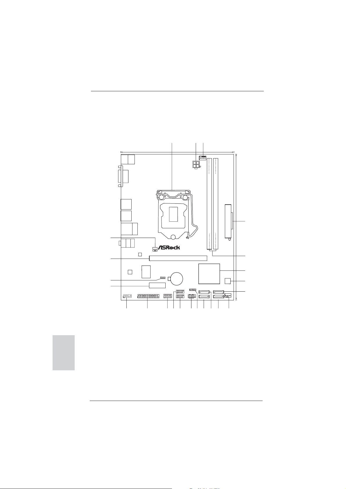
Motherboard Layout
(H61M-VGS R2.0 / H61M-VS R2.0)
3
1
17.3cm (6.8in)
Keyboard
Mouse
PS2
PS2
DX10.1
VGA1
ErP/EuP Ready
USB2.0
T: US B0
B:USB1
USB2.0
T: US B2
B:USB3
USB 2.0
Top:
T:USB4
RJ-45
B: USB5
23
22
Bottom:
MIC IN
Top:
LINE IN
Center:
FRONT
PWR_FAN1
LAN
PHY
PCIE1
2
CPU_FAN1
ATX12 V1
RoHS
PCI Express2.0
Designed in Taipei
DR3
D
DDR3_A1 (64bit, 240-pin module)
Dual Channel
DDR3_B1 (64bit, 240-pin module)
22.6cm (8.9in)
4
ATXPWR1
5
English
2
Super
AUDIO
CODEC
I/O
CLRCMOS1
CMOS
1
21
20
HD_AUDIO1
1
19
PCIE2
1
LPT1
18
Battery
USB8_9
1
COM1
USB6_7
1
1
15
16
17
Intel
H61
SATA2_3
1
SPEAKER1
PLEDPWRBTN
1
HDLED RESET
SATA2_2
PANEL1
12
14
13
32Mb
BIOS
SATA2_1
CHA_FAN1
SATA2_0
11
9
10
6
7
8
1 1155-Pin CPU Socket 13 Chassis Speaker Header (SPEAKER 1, White)
2 ATX 12V Power Connector (ATX12V1) 14 System Panel Header (PANEL1, White)
3 CPU Fan Connector (CPU_FAN1) 15 USB 2.0 Header (USB6_7, Blue)
4 ATX Power Connector (ATXPWR1) 16 USB 2.0 Header (USB8_9, Blue)
5 2 x 240-pin DDR3 DIMM Slots 17 COM Port Header (COM1)
(Dual Channel: DDR3_A1, DDR3_B1, Blue) 18 Print Port Header (LPT1, White)
6 Intel H61 Chipset 19 PCI Express 2.0 x1 Slot (PCIE2, White)
7 32Mb SPI Flash 20 Clear CMOS Jumper (CLRCMOS1)
8 SATA2 Connector (SATA2_1, Blue) 21 PCI Express 2.0 x16 Slot (PCIE1, Blue)
9 Chassis Fan Connector (CHA_FAN1) 22 Front Panel Audio Header
10 SATA2 Connector (SATA2_0, Blue) (HD_AUDIO1, White)
11 SATA2 Connector (SATA2_3, Blue) 23 Power Fan Connector (PWR_FAN1)
12 SATA2 Connector (SATA2_2, Blue)
ASRock H61M-VGS R2.0 / H61M-VS R2.0 Motherboard
Page 3
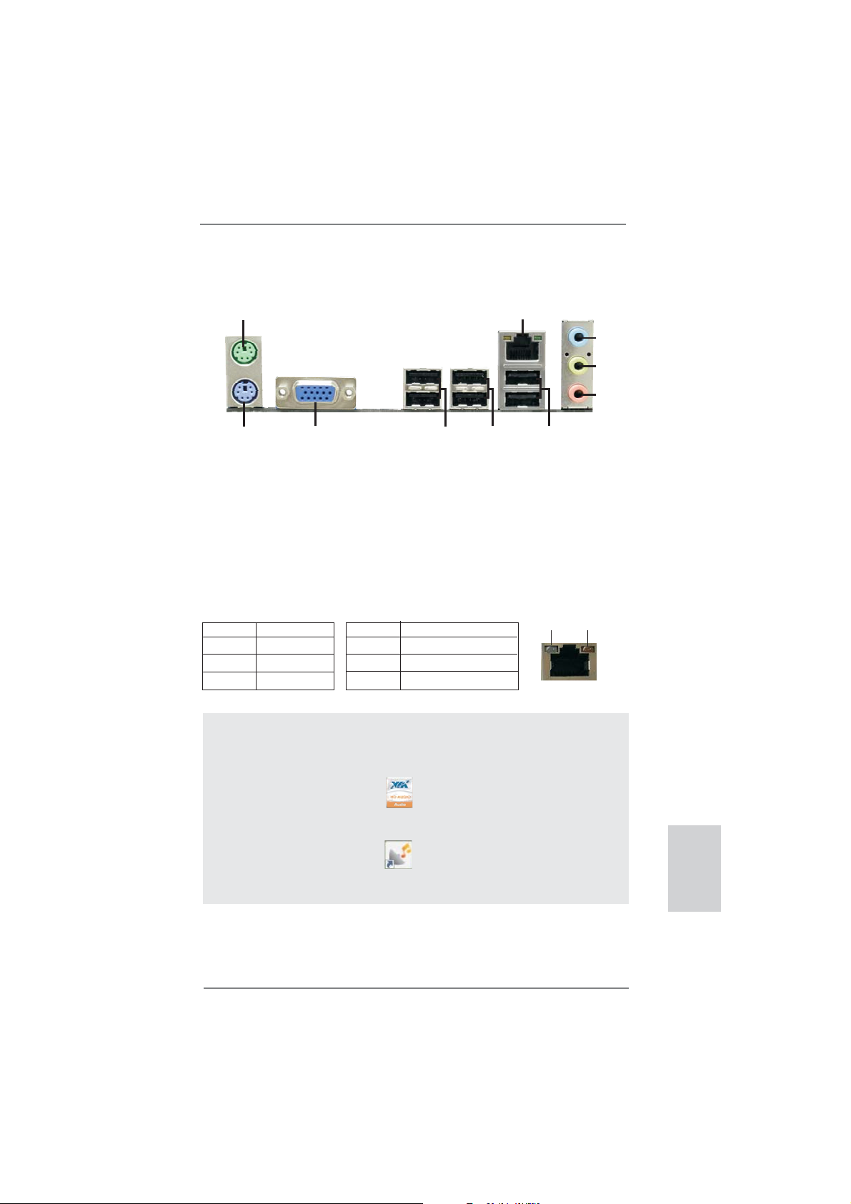
I/O Panel (H61M-VGS R2.0)
1
2
3
4
5
10
1 PS/2 Mouse Port (Green) 6 USB 2.0 Ports (USB45)
* 2 LAN RJ-45 Port 7 USB 2.0 Ports (USB23)
3 Line In (Light Blue) 8 USB 2.0 Ports (USB01)
** 4 Front Speaker (Lime) 9 VGA Port
5 Microphone (Pink) 10 PS/2 Keyboard Port (Purple)
* There are two LED next to the LAN port. Please refer to the table below for the LAN port LED
indications.
Activity/Link LED SPEED LED
Status Description Status Description
9
LAN Port LED Indications
8
7
6
ACT/LINK
LED
SPEED
LED
Off No Link Off 10Mbps connection
Blinking Data Activity Orange 100Mbps connection
On Link Green 1Gbps connection
LAN Port
To enable Multi-Streaming function, you need to connect a front panel audio cable to the front
panel audio header. After restarting your computer, you will fi nd “VIA HD Audio Deck” tool on
your system. Please follow below instructions according to the OS you install.
For Windows® XP / XP 64-bit OS:
Please click “VIA HD Audio Deck” icon , and click “Speaker”. Then you are allowed to
select “2 Channel” or “4 Channel”. Click “Power” to save your change.
For Windows
Please click “VIA HD Audio Deck” icon , and click “Advanced Options” on the left side
on the bottom. In “Advanced Options” screen, select “Independent Headphone”, and click
“OK” to save your change.
®
7 / 7 64-bit / VistaTM / VistaTM 64-bit OS:
ASRock H61M-VGS R2.0 / H61M-VS R2.0 Motherboard
English
3
Page 4
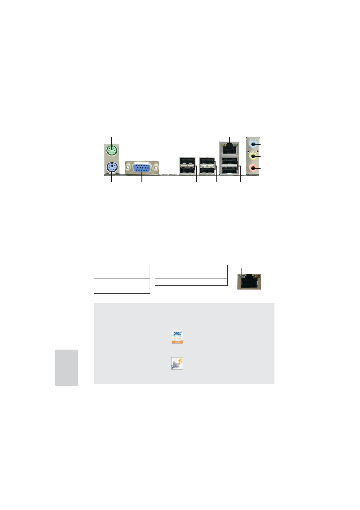
I/O Panel (H61M-VS R2.0)
1
2
3
4
5
10
1 PS/2 Mouse Port (Green) 6 USB 2.0 Ports (USB45)
* 2 LAN RJ-45 Port 7 USB 2.0 Ports (USB23)
3 Line In (Light Blue) 8 USB 2.0 Ports (USB01)
** 4 Front Speaker (Lime) 9 VGA Port
5 Microphone (Pink) 10 PS/2 Keyboard Port (Purple)
* There are two LED next to the LAN port. Please refer to the table below for the LAN port LED
indications.
Activity/Link LED SPEED LED
Status Description Status Description
9
LAN Port LED Indications
8
7
6
ACT/LINK
LED
SPEED
LED
Off No Link Off 10Mbps connection
Blinking Data Activity Orange 100Mbps connection
On Link
LAN Port
To enable Multi-Streaming function, you need to connect a front panel audio cable to the front
panel audio header. After restarting your computer, you will fi nd “VIA HD Audio Deck” tool on
your system. Please follow below instructions according to the OS you install.
For Windows® XP / XP 64-bit OS:
Please click “VIA HD Audio Deck” icon , and click “Speaker”. Then you are allowed to
English
select “2 Channel” or “4 Channel”. Click “Power” to save your change.
For Windows
Please click “VIA HD Audio Deck” icon , and click “Advanced Options” on the left side
on the bottom. In “Advanced Options” screen, select “Independent Headphone”, and click
“OK” to save your change.
®
7 / 7 64-bit / VistaTM / VistaTM 64-bit OS:
4
ASRock H61M-VGS R2.0 / H61M-VS R2.0 Motherboard
Page 5
1. Introduction
Thank you for purchasing ASRock H61M-VGS R2.0 / H61M-VS R2.0 motherboard,
a reliable motherboard produced under ASRock’s consistently stringent quality control. It delivers excellent performance with robust design conforming to ASRock’s
commitment to quality and endurance.
This Quick Installation Guide contains introduction of the motherboard and step-bystep installation guide. More detailed information of the motherboard can be found
in the user manual presented in the Support CD.
Because the motherboard specifi cations and the BIOS software might be
updated, the content of this manual will be subject to change without notice. In case any modifi cations of this manual occur, the updated version
will be available on ASRock website without further notice. You may fi nd
the latest VGA cards and CPU support lists on ASRock website as well.
ASRock website http://www.asrock.com
If you require technical support related to this motherboard, please visit
our website for specifi c information about the model you are using.
www.asrock.com/support/index.asp
1.1 Package Contents
ASRock H61M-VGS R2.0 / H61M-VS R2.0 Motherboard
(Micro ATX Form Factor: 8.9-in x 6.8-in, 22.6 cm x 17.3 cm)
ASRock H61M-VGS R2.0 / H61M-VS R2.0 Quick Installation Guide
ASRock H61M-VGS R2.0 / H61M-VS R2.0 Support CD
2 x Serial ATA (SATA) Data Cables (Optional)
1 x I/O Panel Shield
ASRock Reminds You...
To get better performance in Windows® 7 / 7 64-bit / Vista
bit, it is recommended to set the BIOS option in Storage Confi guration to
AHCI mode. For the BIOS setup, please refer to the “User Manual” in our
support CD for details.
TM
/ VistaTM 64-
ASRock H61M-VGS R2.0 / H61M-VS R2.0 Motherboard
English
5
Page 6
English
1.2 Specifications
Platform - Micro ATX Form Factor: 8.9-in x 6.8-in, 22.6 cm x 17.3 cm
- Solid Capacitor for CPU power
CPU - Supports 2nd Generation Intel
LGA1155 Package
- Supports Intel
®
Turbo Boost 2.0 Technology
- Supports K-Series unlocked CPU
- Supports Hyper-Threading Technology (see CAUTION 1)
Chipset - Intel® H61
Memory - Dual Channel DDR3 Memory Technology (see CAUTION 2)
- 2 x DDR3 DIMM slots
- Supports DDR3 1333/1066 non-ECC, un-buffered
memory
- Max. capacity of system memory: 16GB (see CAUTION 3)
Expansion Slot - 1 x PCI Express 2.0 x16 slot (blue @ x16 mode)
- 1 x PCI Express 2.0 x1 slot
Graphics - Supports Intel
®
HD Graphics Built-in Visuals: Intel® Quick
Sync Video, Intel® Clear Video HD Technology, Intel® HD
Graphics 2000/3000, Intel® Advanced Vector Extensions
(AVX)
- Pixel Shader 4.1, DirectX 11 with Intel® Ivy Bridge CPU,
DirectX 10.1 with Intel
®
- Max. shared memory 1759MB (see CAUTION 4)
- Supports D-Sub with max. resolution up to 2048x1536
@ 75Hz
Audio - 5.1 CH HD Audio (VIA
LAN - H61M-VGS R2.0
Realtek PCIE x1 Gigabit LAN RTL8111E,
speed 10/100/1000 Mb/s
- H61M-VS R2.0
Realtek PCIE x1 LAN RTL8105E, speed 10/100 Mb/s
- Supports Wake-On-LAN
- Supports PXE
Rear Panel I/O I/O Panel
- 1 x PS/2 Mouse Port
- 1 x PS/2 Keyboard Port
- 1 x VGA Port
- 6 x Ready-to-Use USB 2.0 Ports
- 1 x RJ-45 LAN Port with LED (ACT/LINK LED and SPEED
LED)
®
CoreTM i7 / i5 / i3 in
Sandy Bridge CPU
®
VT1705 Audio Codec)
6
ASRock H61M-VGS R2.0 / H61M-VS R2.0 Motherboard
Page 7
- HD Audio Jack: Line in/Front Speaker/Microphone
Connector - 4 x SATA2 3.0 Gb/s connectors, support NCQ, AHCI and
Hot Plug functions
- 1 x Print Port header
- 1 x COM port header
- CPU/Chassis/Power FAN connector
- 24 pin ATX power connector
- 4 pin 12V power connector
- Front panel audio connector
- 2 x USB 2.0 headers (support 4 USB 2.0 ports)
BIOS Feature - 32Mb AMI BIOS
- AMI UEFI Legal BIOS with GUI support
- Supports “Plug and Play”
- ACPI 1.1 Compliance Wake Up Events
- Supports jumperfree
- SMBIOS 2.3.1 Support
- IGPU, DRAM, PCH, CPU PLL, VTT, VCCSA Voltage
Multi-adjustment
Support CD - Drivers, Utilities, AntiVirus Software (Trial Version),
CyberLink MediaEspresso 6.5 Trial, ASRock Software Suite
(CyberLink DVD Suite - OEM and Trial; Creative Sound
Blaster X-Fi MB - Trial; ASRock MAGIX Multimedia Suite OEM)
Unique Feature - ASRock Extreme Tuning Utility (AXTU) (see CAUTION 5)
- ASRock Instant Boot
- ASRock Instant Flash (see CAUTION 6)
- ASRock APP Charger (see CAUTION 7)
- ASRock SmartView (see CAUTION 8)
- ASRock XFast USB (see CAUTION 9)
- ASRock XFast LAN (see CAUTION 10)
- Hybrid Booster:
- ASRock U-COP (see CAUTION 11)
- Boot Failure Guard (B.F.G.)
- Combo Cooler Option (C.C.O.) (see CAUTION 12)
- Good Night LED
Hardware - CPU Temperature Sensing
Monitor - Chassis Temperature Sensing
- CPU/Chassis/Power Fan Tachometer
- CPU/Chassis Quiet Fan (Allow Chassis Fan Speed
Auto-Adjust by CPU Temperature)
- CPU/Chassis Fan Multi-Speed Control
- Voltage Monitoring: +12V, +5V, +3.3V, CPU Vcore
ASRock H61M-VGS R2.0 / H61M-VS R2.0 Motherboard
English
7
Page 8

English
OS - Microsoft® Windows® 7 / 7 64-bit / Vista
TM
/ VistaTM 64-bit
/ XP / XP 64-bit compliant
Certifi cations - FCC, CE, WHQL
- ErP/EuP Ready (ErP/EuP ready power supply is required)
(see CAUTION 13)
* For detailed product information, please visit our website: http://www.asrock.com
WARNING
Please realize that there is a certain risk involved with overclocking, including
adjusting the setting in the BIOS, applying Untied Overclocking Technology, or
using the third-party overclocking tools. Overclocking may affect your system
stability, or even cause damage to the components and devices of your system.
It should be done at your own risk and expense. We are not responsible for possible
damage caused by overclocking.
CAUTION!
1. About the setting of “Hyper Threading Technology”, please check page
39 of “User Manual” in the support CD.
2. This motherboard supports Dual Channel Memory Technology. Before
you implement Dual Channel Memory Technology, make sure to read the
installation guide of memory modules on page 14 for proper installation.
3. Due to the operating system limitation, the actual memory size may be
less than 4GB for the reservation for system usage under Windows
VistaTM / XP. For Windows® OS with 64-bit CPU, there is no such limitation.
4. The maximum shared memory size is defi ned by the chipset vendor and
is subject to change. Please check Intel
tion.
5. ASRock Extreme Tuning Utility (AXTU) is an all-in-one tool to fi ne-tune
different system functions in a user-friendly interface, which is including
Hardware Monitor, Fan Control, Overclocking, OC DNA and IES. In
Hardware Monitor, it shows the major readings of your system. In Fan
Control, it shows the fan speed and temperature for you to adjust. In
Overclocking, you are allowed to overclock CPU frequency for optimal
system performance. In OC DNA, you can save your OC settings as a
profi le and share with your friends. Your friends then can load the OC
profi le to their own system to get the same OC settings. In IES (Intelligent
Energy Saver), the voltage regulator can reduce the number of output
phases to improve effi ciency when the CPU cores are idle without
sacrificing computing performance. Please visit our website for the
operation procedures of ASRock Extreme Tuning Utility (AXTU).
ASRock website: http://www.asrock.com
®
website for the latest informa-
®
7 /
8
ASRock H61M-VGS R2.0 / H61M-VS R2.0 Motherboard
Page 9
6. ASRock Instant Flash is a BIOS fl ash utility embedded in Flash ROM.
This convenient BIOS update tool allows you to update system BIOS
without entering operating systems fi rst like MS-DOS or Windows®. With
this utility, you can press <F6> key during the POST or press <F2> key to
BIOS setup menu to access ASRock Instant Flash. Just launch this tool
and save the new BIOS fi le to your USB fl ash drive, fl oppy disk or hard
drive, then you can update your BIOS only in a few clicks without prepar-
ing an additional fl oppy diskette or other complicated fl ash utility. Please
be noted that the USB fl ash drive or hard drive must use FAT32/16/12 fi le
system.
7. If you desire a faster, less restricted way of charging your Apple devices,
such as iPhone/iPod/iPad Touch, ASRock has prepared a wonderful
solution for you - ASRock APP Charger. Simply installing the APP Char-
ger driver, it makes your iPhone charged much quickly from your computer and up to 40% faster than before. ASRock APP Charger allows you
to quickly charge many Apple devices simultaneously and even supports
continuous charging when your PC enters into Standby mode (S1), Suspend to RAM (S3), hibernation mode (S4) or power off (S5). With APP
Charger driver installed, you can easily enjoy the marvelous charging
experience than ever.
ASRock website: http://www.asrock.com/Feature/AppCharger/index.asp
8.
SmartView, a new function of internet browser, is the smart start page for
IE that combines your most visited web sites, your history, your Facebook
friends and your real-time newsfeed into an enhanced view for a more
personal Internet experience. ASRock motherboards are exclusively
equipped with the SmartView utility that helps you keep in touch with
friends on-the-go. To use SmartView feature, please make sure your
OS version is Windows
browser version is IE8. ASRock website: http://www.asrock.com/Feature/
SmartView/index.asp
9. ASRock XFast USB can boost USB storage device performance. The
performance may depend on the property of the device.
10. ASRock XFast LAN provides a faster internet access, which includes
below benefits. LAN Application Prioritization: You can configure your
application priority ideally and/or add new programs. Lower Latency in
Game: After setting online game priority higher, it can lower the latency in
game. Traffi c Shaping: You can watch Youtube HD video and download
fi les simultaneously. Real-Time Analysis of Your Data: With the status
window, you can easily recognize which data streams you are currently
transferring.
11. While CPU overheat is detected, the system will automatically shutdown.
Before you resume the system, please check if the CPU fan on the
motherboard functions properly and unplug the power cord, then plug it
back again. To improve heat dissipation, remember to spray thermal
grease between the CPU and the heatsink when you install the PC sys-
tem.
®
7 / 7 64 bit / VistaTM / VistaTM 64 bit, and your
English
ASRock H61M-VGS R2.0 / H61M-VS R2.0 Motherboard
9
Page 10

12. Combo Cooler Option (C.C.O.) provides the fl exible option to adopt three
different CPU cooler types, Socket LGA 775, LGA 1155 and LGA 1156.
Please be noticed that not all the 775 and 1156 CPU Fan can be used.
13. EuP, stands for Energy Using Product, was a provision regulated by Eu-
ropean Union to defi ne the power consumption for the completed system.
According to EuP, the total AC power of the completed system shall be
under 1.00W in off mode condition. To meet EuP standard, an EuP ready
motherboard and an EuP ready power supply are required. According to
Intel’s suggestion, the EuP ready power supply must meet the standard
of 5v standby power effi ciency is higher than 50% under 100 mA current
consumption. For EuP ready power supply selection, we recommend you
checking with the power supply manufacturer for more details.
English
10
ASRock H61M-VGS R2.0 / H61M-VS R2.0 Motherboard
Page 11
2. Installation
Pre-installation Precautions
Take note of the following precautions before you install motherboard components or change any motherboard settings.
1. Unplug the power cord from the wall socket before touching any
component. Failure to do so may cause severe damage to the
motherboard, peripherals, and/or components.
2. To avoid damaging the motherboard components due to static
electricity, NEVER place your motherboard directly on the carpet or the like. Also remember to use a grounded wrist strap or
touch a safety grounded object before you handle components.
3. Hold components by the edges and do not touch the ICs.
4. Whenever you uninstall any component, place it on a grounded
antstatic pad or in the bag that comes with the component.
5. When placing screws into the screw holes to secure the motherboard to the chassis, please do not over-tighten the screws!
Doing so may damage the motherboard.
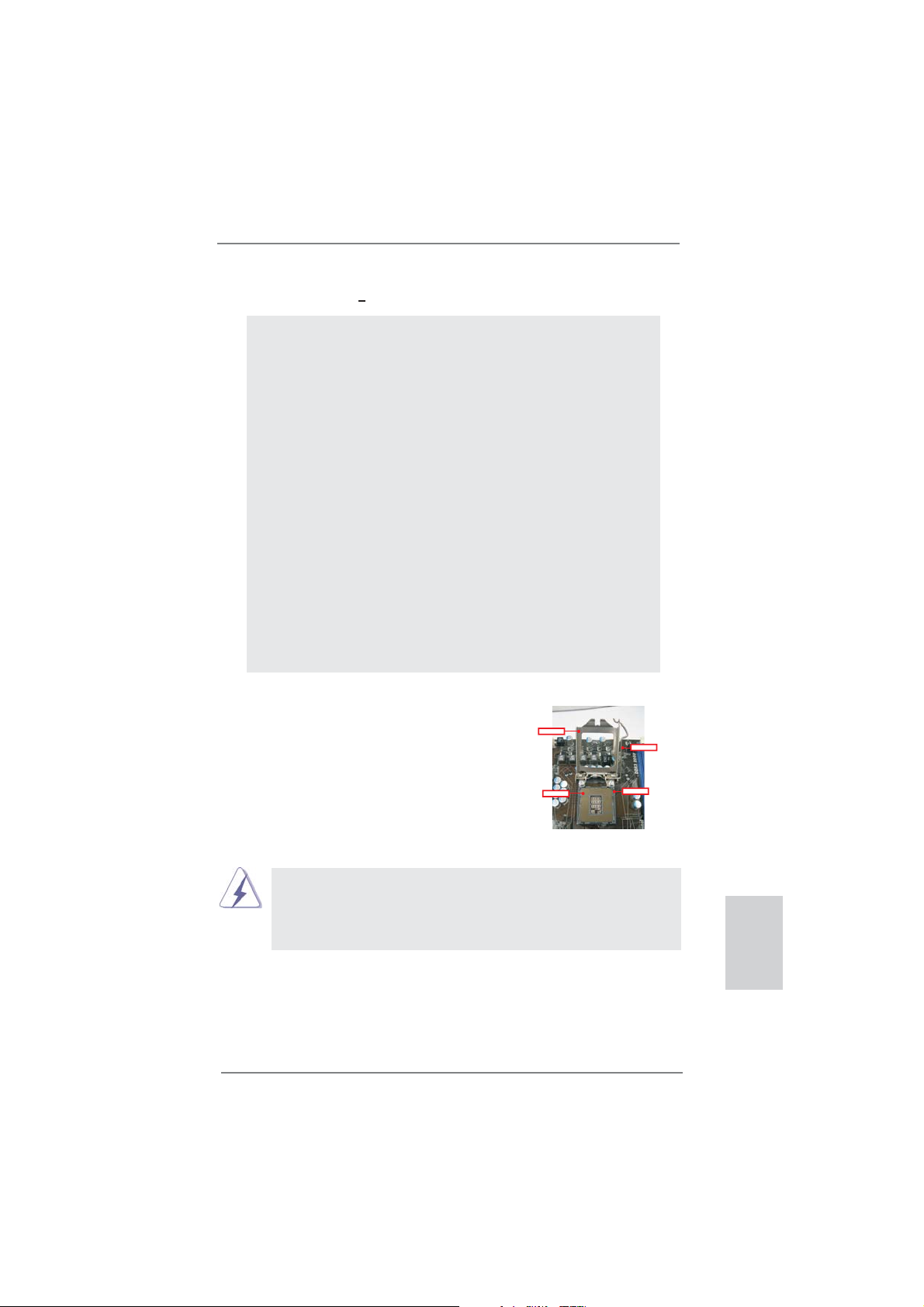
2.1 CPU Installation
For the installation of Intel 1155-Pin CPU,
please follow the steps below.
LoadPlate
LoadLever
ContactArray
1155-Pin Socket Overview
Before you insert the 1155-Pin CPU into the socket, please check if the
CPU surface is unclean or if there is any bent pin on the socket. Do not
force to insert the CPU into the socket if above situation is found. Otherwise, the CPU will be seriously damaged.
SocketBody
ASRock H61M-VGS R2.0 / H61M-VS R2.0 Motherboard
English
11
Page 12
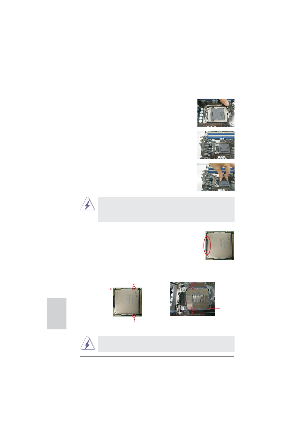
Step 1. Open the socket:
Step 1-1. Disengaging the lever by depressing
down and out on the hook to clear
retention tab.
Step 1-2. Rotate the load lever to fully open po-
sition at approximately 135 degrees.
Step 1-3. Rotate the load plate to fully open po-
sition at approximately 100 degrees.
Step 2. Remove PnP Cap (Pick and Place Cap).
1. It is recommended to use the cap tab to handle and avoid kicking
off the PnP cap.
2. This cap must be placed if returning the motherboard for after
service.
Step 3. Insert the 1155-Pin CPU:
Step 3-1. Hold the CPU by the edges where
are marked with black lines.
black line
English
12
Step 3-2. Orient the CPU with IHS (Integrated
Heat Sink) up. Locate Pin1 and the
two orientation key notches.
orientation key notch
Pin1
orientation key notch
1155-Pin CPU
For proper inserting, please ensure to match the two orientation key
notches of the CPU with the two alignment keys of the socket.
alignment key
alignment key
1155-Pin Socket
ASRock H61M-VGS R2.0 / H61M-VS R2.0 Motherboard
Pin1
Page 13
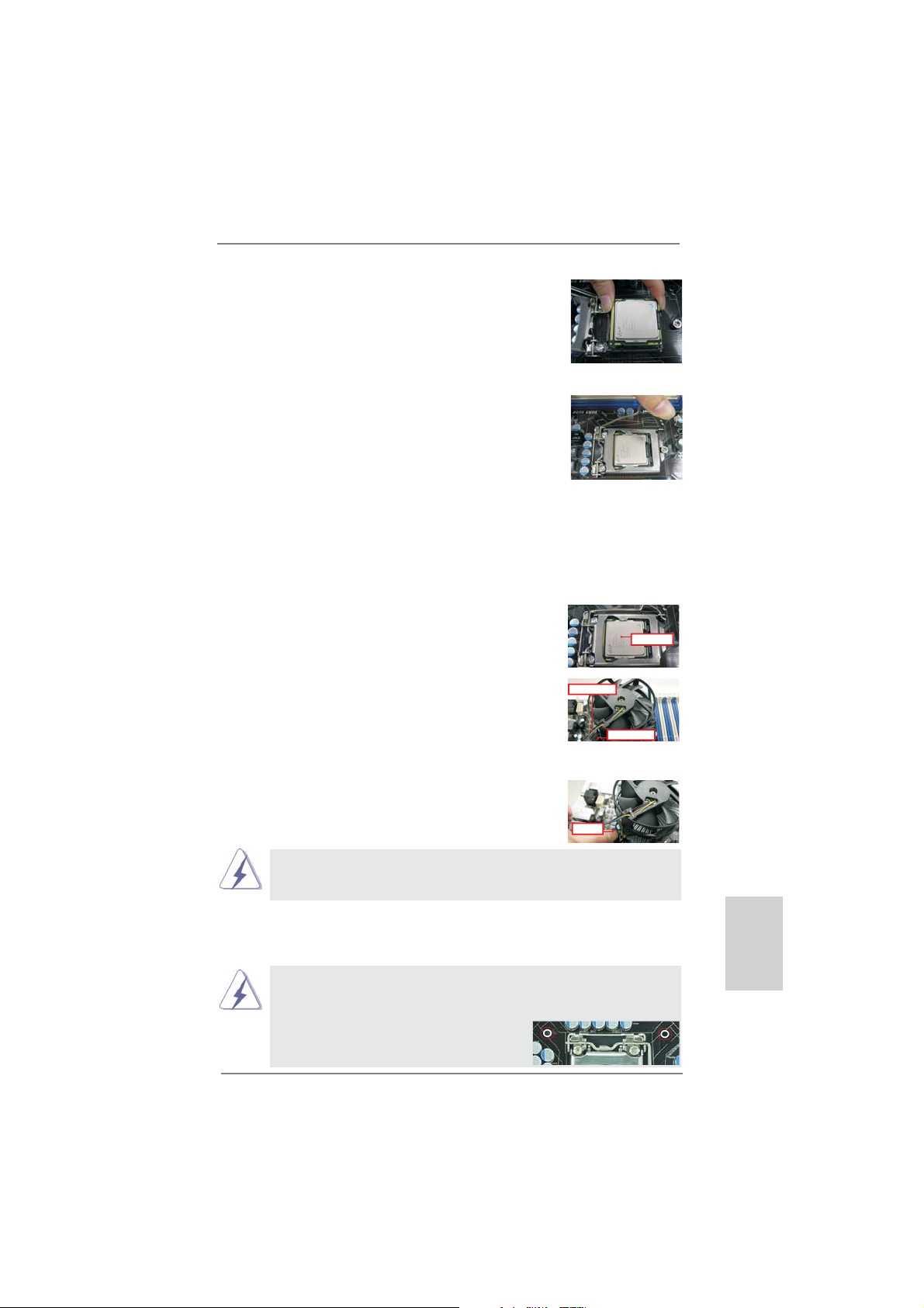
Step 3-3. Carefully place the CPU into the
socket by using a purely vertical motion.
Step 3-4. Verify that the CPU is within the sock-
et and properly mated to the orient
keys.
Step 4. Close the socket:
Step 4-1. Rotate the load plate onto the IHS.
Step 4-2. While pressing down lightly on load
plate, engage the load lever.
2.2 Installation of CPU Fan and Heatsink
For proper installation, please kindly refer to the instruction manuals of your CPU
fan and heatsink.
Below is an example to illustrate the installation of the heatsink for 1155-Pin CPU.
Step 1. Apply thermal interface material onto center of
IHS on the socket surface.
ApplyThermal
InterfaceMaterial
Step 2. Place the heatsink onto the socket. Ensure
fan cables are oriented on side closest to the
CPU fan connector on the motherboard (CPU_
FAN1, see page 2, No. 3).
Fancables on side
closestto MB header
Fastenerslots
pointingstraight out
Step 3. Align fasteners with the motherboard through-
holes.
Step 4. Rotate the fastener clockwise, then press
down on fastener caps with thumb to install
PressDown
and lock. Repeat with remaining fasteners.
If you press down the fasteners without rotating them clockwise, the
heatsink cannot be secured on the motherboard.
(4Places)
Step 5. Connect fan header with the CPU fan connector on the motherboard.
Step 6. Secure excess cable with tie-wrap to ensure cable does not interfere with
fan operation or contact other components.
Please be noticed that this motherboard supports Combo Cooler
Option (C.C.O.), which provides the fl exible option to adopt three dif-
ferent CPU cooler types, Socket LGA 775, LGA 1155 and LGA 1156.
The white throughholes are for Socket LGA
1155/1156 CPU fan.
ASRock H61M-VGS R2.0 / H61M-VS R2.0 Motherboard
English
13
Page 14
2.3 Installation of Memory Modules (DIMM)
This motherboard provides two 240-pin DDR3 (Double Data Rate 3) DIMM slots,
and supports Dual Channel Memory Technology. For dual channel configuration,
you always need to install two identical (the same brand, speed, size and chiptype) memory modules in the DDR3 DIMM slots to activate Dual Channel Memory
Technology. Otherwise, it will operate at single channel mode.
1. It is not allowed to install a DDR or DDR2 memory module into
DDR3 slot;otherwise, this motherboard and DIMM may be
damaged.
2. If you install only one memory module or two non-identical
memory modules, it is unable to activate the Dual Channel
Memory Technology.
3. Some DDR3 1GB double-sided DIMMs with 16 chips may not
work on this motherboard. It is not recommended to install them
on this motherboard.
Installing a DIMM
Please make sure to disconnect power supply before adding or
removing DIMMs or the system components.
Step 1. Unlock a DIMM slot by pressing the retaining clips outward.
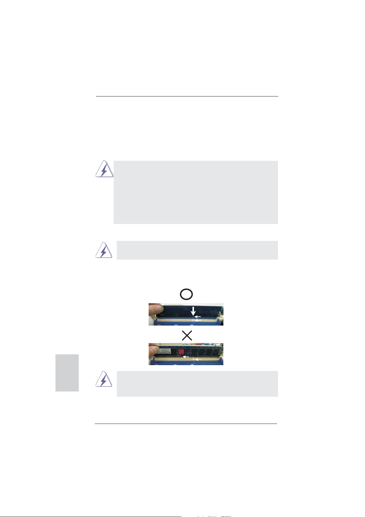
Step 2. Align a DIMM on the slot such that the notch on the DIMM matches the
break on the slot.
English
notch
break
notch
break
The DIMM only fi ts in one correct orientation. It will cause permanent
damage to the motherboard and the DIMM if you force the DIMM into
the slot at incorrect orientation.
Step 3. Firmly insert the DIMM into the slot until the retaining clips at both ends
fully snap back in place and the DIMM is properly seated.
14
ASRock H61M-VGS R2.0 / H61M-VS R2.0 Motherboard
Page 15
2.4 Expansion Slots (PCI Express Slots)
There are 2 PCI Express slots on this motherboard.
PCIE slots:
PCIE1 (PCIE x16 slot; Blue) is used for PCI Express x16 lane width
graphics cards.
PCIE2 (PCIE x1 slot; White) is used for PCI Express cards with x1 lane
width cards, such as Gigabit LAN card, SATA2 card, etc.
Installing an expansion card
Step 1. Before installing the expansion card, please make sure that the power
supply is switched off or the power cord is unplugged. Please read the
documentation of the expansion card and make necessary hardware
settings for the card before you start the installation.
Step 2. Remove the system unit cover (if your motherboard is already installed
in a chassis).
Step 3. Remove the bracket facing the slot that you intend to use. Keep the
screws for later use.
Step 4. Align the card connector with the slot and press fi rmly until the card is
completely seated on the slot.
Step 5. Fasten the card to the chassis with screws.
Step 6. Replace the system cover.
ASRock H61M-VGS R2.0 / H61M-VS R2.0 Motherboard
English
15
Page 16

2.5 Multi Monitor Feature
This motherboard supports multi monitor upgrade. With the internal VGA output support and external add-on PCI Express VGA cards, you can easily enjoy the benefi ts
of multi monitor feature.
Please refer to the following steps to set up a multi monitor environment:
1. Install the PCI Express VGA card on PCIE1 slot. Please refer to page 15 for
proper expansion card installation procedures for details.
2. Connect D-Sub monitor cable to VGA port on the I/O panel. Then connect
other monitor cables to the corresponding connectors of the add-on PCI Express
VGA card on PCIE1 slot.
VGA port
3. Boot your system. Press <F2> or <Del> to enter UEFI setup. Enter “Onboard
VGA Share Memory” option to adjust the memory capability to [32MB], [64MB],
[128MB], [256MB] or [512MB] to enable the function of VGA. Please make sure
that the value you select is less than the total capability of the system memory.
If you do not adjust the UEFI setup, the default value of “Onboard VGA Share
Memory”, [Auto], will disable VGA function when the add-on VGA card is inserted
to this motherboard.
4. Install the onboard VGA driver and the add-on PCI Express VGA card driver to
your system. If you have installed the drivers already, there is no need to install
them again.
5. Set up a multi-monitor display.
English
For Windows
Right click the desktop, choose “Properties”, and select the “Settings” tab
so that you can adjust the parameters of the multi-monitor according to
the steps below.
A. Click the “Identify” button to display a large number on each monitor.
B. Right-click the display icon in the Display Properties dialog that you
wish to be your primary monitor, and then select “Primary”. When
you use multiple monitors with your card, one monitor will always be
Primary, and all additional monitors will be designated as Secondary.
C. Select the display icon identifi ed by the number 2.
D. Click “Extend my Windows desktop onto this monitor”.
E. Right-click the display icon and select “Attached”, if necessary.
®
XP / XP 64-bit OS:
16
ASRock H61M-VGS R2.0 / H61M-VS R2.0 Motherboard
Page 17

F. Set the “Screen Resolution” and “Color Quality” as appropriate for the
second monitor. Click “Apply” or “OK” to apply these new values.
G. Repeat steps C through E for the diaplay icon identifi ed by the number
one, two and three.
For Windows
®
7 / 7 64-bit / VistaTM / VistaTM 64-bit OS:
Right click the desktop, choose “Personalize”, and select the “Display
Settings” tab so that you can adjust the parameters of the multi-monitor
according to the steps below.
A. Click the number ”2” icon.
B. Click the items “This is my main monitor” and “Extend the desktop onto
this monitor”.
C. Click “OK” to save your change.
D. Repeat steps A through C for the display icon identifi ed by the number
three.
6. Use multi monitor. Click and drag the display icons to positions representing the
physical setup of your monitors that you would like to use. The placement
of display icons determines how you move items from one monitor to another.
ASRock H61M-VGS R2.0 / H61M-VS R2.0 Motherboard
English
17
Page 18

2.6 Jumpers Setup
The illustration shows how jumpers are
setup. When the jumper cap is placed on
pins, the jumper is “Short”. If no jumper cap
is placed on pins, the jumper is “Open”. The
illustration shows a 3-pin jumper whose
pin1 and pin2 are “Short” when jumper cap
is placed on these 2 pins.
Jumper Setting Description
Clear CMOS Jumper
(CLRCMOS1)
(see p.2, No. 20)
Note: CLRCMOS1 allows you to clear the data in CMOS. To clear and reset the
system parameters to default setup, please turn off the computer and unplug
the power cord from the power supply. After waiting for 15 seconds, use a
jumper cap to short pin2 and pin3 on CLRCMOS1 for 5 seconds. However,
please do not clear the CMOS right after you update the BIOS. If you need
to clear the CMOS when you just fi nish updating the BIOS, you must boot
up the system fi rst, and then shut it down before you do the clear-CMOS ac-
tion. Please be noted that the password, date, time, user default profi le, 1394
GUID and MAC address will be cleared only if the CMOS battery is removed.
Clear CMOSDefault
English
18
ASRock H61M-VGS R2.0 / H61M-VS R2.0 Motherboard
Page 19

2.7 Onboard Headers and Connectors
Onboard headers and connectors are NOT jumpers. Do NOT place
jumper caps over these headers and connectors. Placing jumper caps
over the headers and connectors will cause permanent damage of the
motherboard!
Serial ATAII Connectors These four Serial ATAII
(SATA2_0: see p.2, No. 10)
(SATA2_1: see p.2, No. 8)
(SATA2_2: see p.2, No. 12)
(SATA2_3: see p.2, No. 11)
SATA2_3
(SATAII) connectors support
SATA data cables for internal
storage devices. The current
SATA2_2
SATAII interface allows up to
SATA2_1
SATA2_0
3.0 Gb/s data transfer rate.
Serial ATA (SATA) Either end of the SATA data
Data Cable cable can be connected to the
(Optional)
SATA / SATAII hard disk or the
SATAII connector on this
motherboard.
USB 2.0 Headers Besides six default USB 2.0
(9-pin USB6_7)
(see p.2 No. 15)
ports on the I/O panel, there
are two USB 2.0 headers on
this motherboard. Each
USB 2.0 header can support
two USB 2.0 ports.
(9-pin USB8_9)
(see p.2 No. 16)
1
USB_PWR
P-9
P-8
USB_PWR
P+9
P+8
GND
GND
DUMMY
Print Port Header This is an interface for print
(25-pin LPT1)
(see p.2 No. 18)
port cable that allows
convenient connection of printer
devices.
1
AFD#
STB#
ERROR#
PINIT#
SPD1
SPD0
SLIN#
SPD2
SPD3
SPD4
SPD5
SPD6
GND
SPD7
ACK#
BUSY
PE
SLCT
ASRock H61M-VGS R2.0 / H61M-VS R2.0 Motherboard
English
19
Page 20

Front Panel Audio Header This is an interface for front
(9-pin HD_AUDIO1)
(see p.2 No. 22)
panel audio cable that allows
convenient connection and
control of audio devices.
1
GND
PRESENCE#
MIC2_R
MIC2_L
MIC_RET
J_SENSE
OUT2_R
OUT_RET
OUT2_L
1. High Defi nition Audio supports Jack Sensing, but the panel wire on
the chassis must support HDA to function correctly. Please follow the
instruction in our manual and chassis manual to install your system.
2. If you use AC’97 audio panel, please install it to the front panel audio
header as below:
A. Connect Mic_IN (MIC) to MIC2_L.
B. Connect Audio_R (RIN) to OUT2_R and Audio_L (LIN) to OUT2_L.
C. Connect Ground (GND) to Ground (GND).
D. MIC_RET and OUT_RET are for HD audio panel only. You don’t
need to connect them for AC’97 audio panel.
System Panel Header This header accommodates
(9-pin PANEL1)
(see p.2 No. 14)
several system front panel
functions.
Connect the power switch, reset switch and system status indicator on the
chassis to this header according to the pin assignments below. Note the
positive and negative pins before connecting the cables.
English
PWRBTN (Power Switch):
Connect to the power switch on the chassis front panel. You may confi gure
the way to turn off your system using the power switch.
RESET (Reset Switch):
Connect to the reset switch on the chassis front panel. Press the reset
switch to restart the computer if the computer freezes and fails to perform a
normal restart.
PLED (System Power LED):
Connect to the power status indicator on the chassis front panel. The LED
is on when the system is operating. The LED keeps blinking when the system is in S1 sleep state. The LED is off when the system is in S3/S4 sleep
state or powered off (S5).
HDLED (Hard Drive Activity LED):
Connect to the hard drive activity LED on the chassis front panel. The LED
is on when the hard drive is reading or writing data.
20
ASRock H61M-VGS R2.0 / H61M-VS R2.0 Motherboard
Page 21

The front panel design may differ by chassis. A front panel module mainly
consists of power switch, reset switch, power LED, hard drive activity LED,
speaker and etc. When connecting your chassis front panel module to this
header, make sure the wire assignments and the pin assign-ments are
matched correctly.
Chassis Speaker Header Please connect the chassis
(4-pin SPEAKER 1)
(see p.2 No. 13)
speaker to this header.
Chassis and Power Fan Connectors Please connect the fan cables
(4-pin CHA_FAN1)
(see p.2 No. 9)
match the black wire to the
to the fan connectors and
CHA_FAN_SPEED
+12V
FAN_SPEED_CONTROL
GND
ground pin.
(3-pin PWR_FAN1)
(see p.2 No. 23)
CPU Fan Connectors Please connect the CPU fan
(4-pin CPU_FAN1)
(see p.2 No. 3)
cable to the connector and
match the black wire to the
ground pin.
Though this motherboard provides 4-Pin CPU fan (Quiet Fan) support, the 3-Pin
CPU fan still can work successfully even without the fan speed control function.
If you plan to connect the 3-Pin CPU fan to the CPU fan connector on this
motherboard, please connect it to Pin 1-3.
ATX Power Connector Please connect an ATX power
(24-pin ATXPWR1)
(see p.2 No. 4)
supply to this connector.
Though this motherboard provides 24-pin ATX power connector,
it can still work if you adopt a traditional 20-pin ATX power supply.
To use the 20-pin ATX power supply, please plug your
power supply along with Pin 1 and Pin 13.
4 3 2 1
+12V
FAN_SPEED_CONTROL
CPU_FAN_SPEED
12 124
GND
Pin 1-3 Connected
3-Pin Fan Installation
13
12
24
English
20-Pin ATX Power Supply Installation
1
ASRock H61M-VGS R2.0 / H61M-VS R2.0 Motherboard
13
21
Page 22

ATX 12V Power Connector Please connect an ATX 12V
(4-pin ATX12V1)
(see p.2 No. 2)
power supply to this connector.
Serial port Header This COM1 header supports a
(9-pin COM1)
(see p.2 No. 17)
serial port module.
English
22
ASRock H61M-VGS R2.0 / H61M-VS R2.0 Motherboard
Page 23

2.8 Driver Installation Guide
To install the drivers to your system, please insert the support CD to your optical
drive fi rst. Then, the drivers compatible to your system can be auto-detected and
listed on the support CD driver page. Please follow the order from up to bottom side
to install those required drivers. Therefore, the drivers you install can work properly.
2.9 Installing Windows® 7 / 7 64-bit / Vista
TM
/ Vista
TM
64-bit / XP
/ XP 64-bit Without RAID Functions
If you want to install Windows® 7 / 7 64-bit / VistaTM / VistaTM 64-bit / XP / XP 64bit OS on your SATA / SATAII HDDs without RAID functions, please follow below
procedures according to the OS you install.
2.9.1 Installing Windows® XP / XP 64-bit Without RAID
Functions
If you want to install Windows® XP / XP 64-bit OS on your SATA / SATAII HDDs
without RAID functions, please follow below steps.
Using SATA / SATAII HDDs without NCQ function
STEP 1: Set up UEFI.
A. Enter UEFI SETUP UTILITY Advanced screen SATA Confi guration.
B. Set the option “SATA Mode” to [IDE].
STEP 2: Install Windows
®
XP / XP 64-bit OS on your system.
ASRock H61M-VGS R2.0 / H61M-VS R2.0 Motherboard
English
23
Page 24

2.9.2 Installing Windows® 7 / 7 64-bit / Vista
TM
/ Vista
TM
64-bit
Without RAID Functions
If you want to install Windows® 7 / 7 64-bit / VistaTM / VistaTM 64-bit OS on your SATA
/ SATAII HDDs without RAID functions, please follow below steps.
Using SATA / SATAII HDDs with NCQ function
STEP 1: Set Up UEFI.
A. Enter UEFI SETUP UTILITY Advanced screen SATA Confi guration.
B. Set the option “SATA Mode” to [AHCI].
STEP 2: Install Windows
system.
Using SATA / SATAII HDDs without NCQ function
STEP 1: Set up UEFI.
A. Enter UEFI SETUP UTILITY Advanced screen SATA Confi guration.
B. Set the option “SATA Mode” to [IDE].
STEP 2: Install Windows® 7 / 7 64-bit / VistaTM / VistaTM 64-bit OS on your
system.
®
7 / 7 64-bit / VistaTM / VistaTM 64-bit OS on your
English
24
ASRock H61M-VGS R2.0 / H61M-VS R2.0 Motherboard
Page 25

3. BIOS Information
The Flash Memory on the motherboard stores BIOS Setup Utility. When you start up
the computer, please press <F2> or <Del> during the Power-On-Self-Test (POST)
to enter BIOS Setup utility; otherwise, POST continues with its test routines. If you
wish to enter BIOS Setup after POST, please restart the system by pressing <Ctl>
+ <Alt> + <Delete>, or pressing the reset button on the system chassis. The BIOS
Setup program is designed to be user-friendly. It is a menu-driven program, which
allows you to scroll through its various sub-menus and to select among the predetermined choices. For the detailed information about BIOS Setup, please refer to the
User Manual (PDF fi le) contained in the Support CD.
4. Software Support CD information
®
This motherboard supports various Microsoft
64-bit / VistaTM / Vista
motherboard contains necessary drivers and useful utilities that will enhance motherboard features. To begin using the Support CD, insert the CD into your CD-ROM
drive. It will display the Main Menu automatically if “AUTORUN” is enabled in your
computer. If the Main Menu does not appear automatically, locate and double-click
on the fi le “ASSETUP.EXE” from the BIN folder in the Support CD to display the
menus.
TM
64-bit / XP / XP 64-bit. The Support CD that came with the
Windows® operating systems: 7 / 7
ASRock H61M-VGS R2.0 / H61M-VS R2.0 Motherboard
English
25
Page 26

1. 主板簡介
ASRock提醒您
謝謝你采用了華擎 H61M-VGS R2.0 / H61M-VS R2.0 主板 , 本主板由華擎嚴格制造 ,
質量可靠 , 穩定性好 , 能夠獲得卓越的性能。本安裝指南介紹了安裝主板的步驟。更
加詳細的主板信息可參看驅動光盤的用戶手冊。
由于主板規格和 BIOS 軟件將不斷升級 , 本手冊之相關內容變更恕不另
行通知。請留意華擎网站上公布的升級版本。你也可以在華擎網站找
到最新的顯卡和 CPU 支持表。
華擎网址:http://www.asrock.com
如果您需要與此主板有關的技術支持 , 請參觀我們的網站以了解您使用機
種的規格信息。
www.asrock.com/support/index.asp
1.1 包裝盒內物品
華擎 H61M-VGS R2.0 / H61M-VS R2.0 主板
(Micro ATX 規格 : 8.9 英吋 X 6.8 英吋 , 22.6 厘米 X 17.3 厘米 )
華擎 H61M-VGS R2.0 / H61M-VS R2.0 快速安裝指南
華擎 H61M-VGS R2.0 / H61M-VS R2.0 支持光盤
兩條 Serial ATA(SATA) 數據線 ( 選配 )
一塊 I/O 擋板
簡體中文
26
ASRock提醒您
為了在 Windows
更好的性能,建議您在BIOS中將Storage Configuration(存儲配置)選項
設成AHCI模式。關于BIOS設置程序,請參見支持光盤中的“User Manual”
以了解相詳細信息。
...
®
7 / 7 64-bit / Vista
TM
/ VistaTM 64-bit 系統中取得
ASRock H61M-VGS R2.0 / H61M-VS R2.0 Motherboard
Page 27

1.2 主板規格
架构 - Micro ATX 規格 :
8.9 英吋 X 6.8 英吋 , 22.6 厘米 X 17.3 厘米
- CPU 供電電路固態電容
處理器 - 支持第二代 Intel
- 支持 Intel® Turbo Boost 2.0 技術
- 支持 K- 系列解鎖的 CPU
- 支持 Hyper-Threading 超線程技術(詳見警告 1)
芯片組 - Intel
®
H61
系統內存 - 支持雙通道 DDR3 內存技術(見警告 2)
- 配備 2 個 DDR3 DIMM 插槽
- 支持 DDR3 1333/1066 non-ECC、un-buffered 內存
- 最高支持 16GB 系統容量(見警告 3)
擴展插槽 - 1 x PCI Express 2.0 x16 插槽 ( 藍色 @ x16 模式 )
- 1 x PCI Express 2.0 x1 插槽
板載顯卡 -
支持 Intel® HD Graphics 內置視覺特性 :Intel® Quick Sync
Video、Intel
2000/3000、Intel® Advanced Vector Extensions(AVX)
- Pixel Shader 4.1 技術、Intel® Ivy Bridge CPU 支持
DirectX 11、Intel® Sandy Bridge CPU 支持 DirectX 10.1
- 最大共享內存 1759MB(見警告 4)
- 支持 D-Sub, 最高分辨率達 2048x1536 @ 75Hz
音效 - 5.1 聲道高保真音頻 (VIA
板載 LAN 功能 - H61M-VGS R2.0
Realtek PCIE x1 Gigabit LAN RTL8111E,
速度 :10/100/1000 Mb/s
- H61M-VS R2.0
Realtek PCIE x1 LAN RTL8105E, 速度 :10/100 Mb/s
- 支持网路喚醒(Wake-On-LAN)
- 支持 PXE
Rear Panel I/O 界面
I/O - 1 個 PS/2 鼠標接口
( 后面板輸入 / - 1 個 PS/2 鍵盤接口
輸出接口 ) - 1 個 VGA 接口
- 6 個可直接使用的 USB 2.0 接口
- 1 個 RJ-45 局域网接口與 LED 指示燈 (ACT/LINK LED 和
SPEED LED)
- 高保真音頻插孔:音頻輸入 / 前置喇叭 / 麥克風
連接頭 - 4 x SATA2 3.0Gb/s 連接頭 , 支持 NCQ, AHCI 和熱插拔功
能
- 1 x 打印機端口接針
ASRock H61M-VGS R2.0 / H61M-VS R2.0 Motherboard
®
CoreTM i7 / i5 / i3 處理器 (LGA1155針腳)
®
Clear Video HD 技術、Intel® HD Graphics
®
VT1705 音頻編解碼器 )
簡體中文
27
Page 28

簡體中文
28
- 1 x 串行接口
- CPU/ 機箱 / 電源風扇接頭
- 24 針 ATX 電源接頭
- 4 針 12V 電源接頭
- 前置音頻面板接頭
- 2 x USB 2.0 接口 ( 可支持 4 個額外的 USB 2.0 接口 )
BIOS - 32Mb AMI BIOS
- AMI UEFI Legal BIOS,支持 GUI
- 支持即插即用(Plug and Play,PnP)
- ACPI 1.1 電源管理
- 支持喚醒功能
- 支持 jumperfree 免跳線模式
- IGPU、DRAM、PCH、CPU PLL、VTT、VCCSA 電壓多功能調節器
支持光盤 - 驅動程序 , 工具軟件 , 殺毒軟件(測試版本 ),CyberLink
MediaEspresso 6.5 試用版 , 華擎軟件套裝 (CyberLink DVD
Suite - OEM 試用版 ; Creative Sound Blaster X-Fi MB 試用版 ; 華擎 MAGIX 多媒体套件 - OEM)
獨家功能 - ASRock Extreme Tuning Utility (AXTU)(詳見警告 5)
- 華擎即時開機功能
- 華擎 Instant Flash(見警告 6)
- 華擎 APP Charger(見警告 7)
- 華擎 SmartView(見警告 8)
- 華擎 XFast USB(見警告 9)
- 華擎 XFast LAN(見警告 10)
- Hybrid Booster( 安心超頻技術 ):
- ASRock U-COP(見警告 11)
- Boot Failure Guard (B.F.G., 啟動失敗恢復技術 )
- 組合散熱器選項 (C.C.O.)(見警告 12)
- 晚安指示燈
硬件監控器 - CPU 溫度偵測
- 主板溫度偵測
- CPU/ 機箱 / 電源風扇轉速計
- CPU/ 机箱靜音風扇(允許根据 CPU 溫度自動調整机箱風扇速
度)
- CPU/ 机箱風扇多速控制
- 電壓範圍:+12V, +5V, +3.3V, 核心電壓
操作系統 - Microsoft
®
Windows
®
7/7 64 位元 /VistaTM/Vista
TM
64 位元 /
XP/XP 64 位元适用于此主板
認證 - FCC, CE, WHQL
- 支持 ErP/EuP( 需要同時使用支持 ErP/EuP 的電源供應
器 )(見警告 13)
* 請參閱華擎網站了解詳細的產品信息 : http://www.asrock.com
ASRock H61M-VGS R2.0 / H61M-VS R2.0 Motherboard
Page 29

警告
請了解超頻具有不可避免的風險 , 這些超頻包括調節 BIOS 設置、運用異步超
頻技術或使用第三方超頻工具。超頻可能會影響您的系統穩定性 , 甚至會導
致系統組件和設備的損壞。這種風險和代價須由您自己承擔 , 我們對超頻可
能導致的損壞不承擔責任。
警告!
1、 關于“Hyper-Threading Technology”(超線程技術)的設置,請參考 CD
2、 這款主板支援雙通道內存技術。在您實現雙通道內存技術之前,為能正確
3、 由于操作系統的限制,在 Windows® 7 / Vista
4、 最大共享內存大小由芯片組廠商定義並且可以更改。請查閱 Intel
站了解最新資訊。
5、
6、 華擎 Instant Flash 是一個內建于 Flash ROM 的 BIOS 更新工具程序。這個
7、 若您想要更快速、更自由地為您的蘋果設備,如 iPhone/iPad/iPod
光盤中的“User Manual”( 用戶手冊 , 英文版)第39頁, 或是“UEFI
設置程序”第8頁(中文版)。
安裝,請確認您已經閱讀了第 14 頁的內存模組安裝指南。
際內存容量可能小于 4GB。對於 Windows
不會存在這樣的限制。
ASRock Extreme Tuning Utility (AXTU) 是一個多合一的工具,可在用戶
友好的界面中微調不同的系統功能,包括硬件監控、風扇控制、超頻、OC
DNA 和 IES。在 Hardware Monitor(硬件監控)中,顯示系統的主要參數。
在 Fan Control(風扇控制)中,顯示風扇速度和溫度,以便您進行調整。
在 Overclocking(超頻)中,您可以對 CPU 進行超頻,以优化系統性能。
在 OC DNA 中,您可以將自己的 OC 設置保存為配置文件,并与您的朋友共
享。您的朋友可以將您的 OC 配置文件加載他們的系統中,從而得到相同
的 OC 設置。在 IES(智能節能)中,電壓調節器可以在 CPU 核心空閒時減
少輸出相位數,以提高效率且不影響運計算性能。關于 ASRock Extreme
Tuning Utility (AXTU) 的操作步驟,請訪問我們的网站。
華擎網站:http://www.asrock.com
方便的BIOS 更新工具可讓您無需進入操作系統 ( 如 MS-DOS 或 Windows®)
即可進行 BIOS 的更新。在系統開机自檢過程中按下 < F6> 鍵或在 BIOS 設
置菜單中按下 < F2> 鍵即可進入華擎 Instant Flash 工具程序。啟動這一
程序後 ,只需把新的BIOS文件保存在 U 盤、軟盤或硬盤中 , 輕鬆點擊鼠
標就能完成 BIOS 的更新 ,而不再需要準備額外的軟盤或其他複雜的更新
程序。請注意 :U 盤或硬盤必須使用 FAT32/64 文件系統。
touch 充電 , 華擎為您提供了一個絕妙的解決方案 - 華擎 A PP Charger。
只需安裝 APP Charger 驅動程序 , 用電腦為 iPhone 充電最多可比以往快
40%。華擎 A PP Ch arger 允許您同時為多部蘋果設備快速充電 , 甚至可以
在電腦進入待機 ( S1)、掛起至內存 ( S3)、休眠 (S4) 或關機 ( S5) 模式下
持續為設備充電。只需安裝了 APP Charger 驅動程序 , 您立刻就能擁有非
凡的充電體驗。
TM
/ XP 下,供系統使用的實
®
操作系統搭配 64 位元 CPU 來說 ,
®
網
簡體中文
ASRock H61M-VGS R2.0 / H61M-VS R2.0 Motherboard
29
Page 30

8、 SmartView 是 Internet 瀏覽器的一項新功能,它作為 IE 的智能起始頁
面,在一個增強的視圖中提供您經常訪問的网站、您的遊覽歷史記錄、
您的Facebook朋友、以及您的實時新聞來源,可為您提供更具個性化的
Internet 体驗。
時与朋友保持聯系。為使用 SmartView 功能,請确保您操作系統的版本是
®
Windows
IE8。華擎网站:http://www.asrock.com/Feature/SmartView/index.asp
9、 華擎 XFast USB 可以提升 USB 存儲設備性能。性能可能因設備特性不同而
存在差异。
10、 華擎 XFast LAN 可提供更快的网絡訪問,包括以下諸多好處。网絡應用程
序优先級:您可以設置理想的應用程序优先級,并可以添加新程序。游戲
更少延遲:將在線游戰設置為較高的优先級,可降低游戰中的延遲。流量
定形:您可以在觀看 Youtube 高清視頻的同時進行文件下載。實時分析您
的數据:通過狀態窗口,您可以清楚地看到目前正在傳輸的是哪個數据
流。
11、 當檢測到 CPU 過熱問題時,系統會自動關機。在您重新啟動系統之前,請
檢查主板上的 C PU 風扇是否正常運轉並拔出電源線,然后再將它插回。為
了提高散熱性,在安裝 PC 系統時請在 CPU 和散熱器之間涂一層導熱膠。
12、 組合散熱器選項 (C.C.O.) 提供靈活的選項 , 讓您可使用三種不同的 C P U
散熱器類型 , 分別是 L GA775, L GA1155 與 L GA1156。請注意 : 並非所有的
775 和 1156 CPU 風扇都支持此功能。
13、 EuP, 全稱 Energy Using Product( 能耗產品 ), 是歐盟用來定義完整系統
耗電量的規定。根據 E uP 的規定 , 一個完整系統在關機模式下的交流電總
消耗必須在 1.00W 以下。為滿足 E uP 標準 , 您需要同時具備支持 E uP 的主
板和支持 EuP 的電源供應器。根據 Intel
必須滿足在 100m A 電流消耗時 ,5V sb 電源效率高于 50%。有關支持 E u P 的
電源供應器選擇方面的更多細節 , 我們建議您諮詢電源供應器的製作商。
華擎主板專門配備 SmartView 應實用程序,可幫助您隨
7 / 7 64位元 / VistaTM / VistaTM 64位元,瀏覽器的版本是
®
的建議 , 支持 EuP 的電源供應器
簡體中文
30
ASRock H61M-VGS R2.0 / H61M-VS R2.0 Motherboard
Page 31

1.3 跳線設置
插圖所示的就是設置跳線的方法。當跳線
帽放置在針腳上時 , 這個跳線就是“短
接”。如果針腳上沒有放置跳線帽 , 這個
跳線就是“開路”。插圖顯示了一個 3 針
腳的跳線 , 當跳線帽放置在針腳 1 和針腳 2
之間時就是“短接”。
接腳 設定
清除 CMOS
(CLRCMOS1, 3 針腳跳線 )
(見第2頁第20項)
默認設置
注意: CLRCMOS1允許您清除CMOS中的數据。如要清除并將系統參數恢复至默認
設置,請關閉計算机,然后從電源插座上拔掉電源線。等待 15秒后,使用跳
線帽將CLRCMOS1上的插針 2 和插針 3 短接 5 秒。但是,請勿在更新 BIOS 后
立即清除 CMOS。如果需要在更新 BIOS 后立即清除 CMOS,必須在執行 CMOS
清除操作之前,先啟動然后關閉系統。請注意,只有取出 CMOS 電池,密碼、
日期、時間、用戶默認配置文件、1394 GUID 和 MAC 地址才會被清除。
清除 CMOS
ASRock H61M-VGS R2.0 / H61M-VS R2.0 Motherboard
簡體中文
31
Page 32

1.4 板載接頭和接口
板載接頭和接口不是跳線。切勿將跳線帽放置在這些接頭和接口上。將
跳線帽放置在接頭和接口上將會導致主板的永久性損壞!
Serial ATAII 接口 這裡有四組 Serial ATAII
USB_PWR
P-9
P-8
USB_PWR
P+9
P+8
GND
GND
SATA2_1
SATA2_0
DUMMY
(SATA2_0: 見第 2 頁第 10 項 )
(SATA2_1: 見第 2 頁第8項)
(SATA2_2: 見第 2 頁第 12 項 )
(SATA2_3: 見第 2 頁第 11 項 )
SATA2_3
(SATAII) 接口支持 Serial
(SATA) 數據線作為內部儲存
設置。目前 SATAII 界面理論
SATA2_2
上可提供高達 3.0Gb/s 的數
據傳輸速率。
Serial ATA (SATA) SATA 數據線的任意一端均可
數據線 連接 SATA/SATAII 硬
(選配)
盤或者主板上的 SATAII 接口。
USB 2.0 擴展接頭 除了位於 I/O 面板的六個默
(9 針 USB6_7)
(見第2頁第15項)
認 USB 2.0 接口之外,這款
主板有兩組 USB 2.0 接針。
這組 USB 2.0 接針可以支持
兩個 USB 2.0 接口。
(9 針 USB8_9)
(見第2頁第16項)
1
簡體中文
32
打印機端口接針 這是一個連接打印機端口的
(25 針 LPT1)
(見第2頁第18項)
接口,方便您連接打印機設
前置音頻面板接頭 可以方便連接音頻設備。
(9 針 HD_AUDIO1)
(見第2頁第22項)
AFD#
ERROR#
PINIT#
SLIN#
備。
1
SPD2
SPD1
SPD0
STB#
SPD3
SPD4
1
SPD5
GND
MIC2_L
GND
SPD7
SPD6
PRESENCE#
MIC_RET
OUT2_R
MIC2_R
ACK#
BUSY
J_SENSE
PE
OUT_RET
OUT2_L
SLCT
ASRock H61M-VGS R2.0 / H61M-VS R2.0 Motherboard
Page 33

1. 高保真音頻 (High Definition Audio, HDA) 支持智能音頻接口檢測功能
(Jack Sensing), 但是機箱面板的連線必須支持 HDA 才能正常使用。請按我
們提供的手冊和機箱手冊上的使用說明安裝您的系統。
2. 如果您使用 AC’97 音頻面板 , 請按照下面的步驟將它安裝到前面板音頻接針 :
A. 將 Mic_IN(MIC) 連接到 MIC2_L。
B. 將 Audio_R(RIN) 連接到 OUT2_R, 將 Audio_L(LIN) 連接到
OUT2_L。
C. 將 Ground(GND) 連接到 Ground(GND)。
D. MIC_RET 和 OUT_RET 僅用于 HD 音頻面板。您不必將它們連接到
AC’97 音頻面板。
系統面板接頭 這個接頭提供數個系統前面
(9 針 PANEL1)
(見第2頁第14項)
根據下面的針腳說明連接機箱上的電源開關、重啟按鈕與系統狀態
指示燈到這個排針。根據之前請注意針腳的正負極。
PWRBTN( 電源開關 ):
連接機箱前面板的電源開關。您可以設置用電源鍵關閉系統的方式。
RESET( 重啟開關 ):
連接機箱前面板的重啟開關。當電腦死機且無法正常重新啟動時 , 可
按下重啟開關重新啟動電腦。
PLED( 系統電源指示燈 ):
連接機箱前面板的電源狀態指示燈。當系統運行時 , 此指示燈亮起。
當系統處于 S1 待機模式時 , 此指示燈保持閃爍。當系統處于 S3/S4 待
機模式或關機 (S5) 模式時 , 此指示燈熄滅。
HD LED( 硬盤活動指示燈 ):
連接機箱前面板的硬盤動作指示燈。當硬盤正在讀取或寫入數據時 ,
此指示燈亮起。
板功能。
前面板設計因機箱不同而有差異。前面板模塊一般由電源開關、
重啟開關、電源指示燈、硬盤動作指示燈、喇叭等構成。將您的機
箱前面板連接到此排針時 , 請確認連接線與針腳上的說明相對應。
機箱喇叭接頭 請將機箱喇叭連接到這個接
(4 針 SPEAKER1)
(見第2頁第13項)
頭。
ASRock H61M-VGS R2.0 / H61M-VS R2.0 Motherboard
簡體中文
33
Page 34

機箱 , 電源風扇接頭 請將風扇連接線接到這個
(4 針 CHA_FAN1)
(見第2頁第9項)
(3 針 PWR_FAN1)
(見第2頁第23項)
接頭,並讓黑線與接地的針腳
相接。
CHA_FAN_SPEED
+12V
FAN_SPEED_CONTROL
GND
簡體中文
CPU 風扇接頭 請將 CPU 風扇連接線接到這個
(4 針 CPU_FAN1)
(見第2頁第3項)
接頭,並讓黑線與接地的針腳
相接。
4 3 2 1
+12V
FAN_SPEED_CONTROL
CPU_FAN_SPEED
GND
雖然此主板支持 4-Pin CPU 風扇 (Quiet Fan, 靜音風扇 ), 但是沒有調速功能的
3-Pin CPU 風扇仍然可以在此主板上正常運行。如果您打算將 3-Pin CPU 風扇
連接到此主板的 CPU 風扇接口 , 請將它連接到 Pin 1-3。
Pin 1-3 連接
3-Pin 風扇的安裝
ATX 電源接頭 請將 ATX 電源供應器連接到這
(24 針 ATXPWR1)
(見第2頁第4項)
個接頭。
雖然此主板提供 24-pin ATX 電源接口 , 但是您仍然可以使用
12 124
13
12
傳統的 20-pin ATX 電源。為了使用 20-pin ATX 電源 , 請順著
Pin 1 和 Pin 13 插上電源接頭。
20-Pin ATX 電源安裝說明
1
ATX 12V 接頭 請將一個 ATX 12V 電源供應
(4 針 ATX12V1)
(見第2頁第2項)
器接到這個接頭。
串行接口連接器 這個 COM1 端口支持一個串行
(9 針 COM1)
接口的外設。
(見第2頁第17項)
24
13
34
ASRock H61M-VGS R2.0 / H61M-VS R2.0 Motherboard
Page 35

2. BIOS 信息
主板上的 Flash Memory 存儲了 BIOS 設置程序。請再啟動電腦進行開機自檢 (POST)
時按下<F2> 或<Del>鍵進入 BIOS 設置程序;此外,你也可以讓開機自檢 (POST)
進行常規檢驗。如果你需要在開機自檢 (POST) 之后進入BIOS 設置程序,請按下
<Ctrl>+<Alt>+<Delete> 鍵重新啟動電腦,或者按下系統面板上的重啟按鈕。有關
BIOS 設置的詳細信息,請查閱隨機支持光盤裡的用戶手冊 (PDF 文件 )。
3. 支持光盤信息
本主板支持各種微軟視窗操作系統:Microsoft® Windows® 7/7 64 位元 /VistaTM/
TM
Vista
64 位元 /XP/XP 64 位元。主板隨機支持光盤包含各種有助于提高主板效能的
必要驅動和實用程序。請將隨機支持光盤放入光驅裡,如果電腦的“自動運行”功能
已啟用,屏幕將會自動顯示主菜單。如果主菜單不能自動顯示,請查找支持光盤內
BIN 文件夾下的“ASSETUP.EXE”,并雙擊它,即可調出主菜單。
ASRock H61M-VGS R2.0 / H61M-VS R2.0 Motherboard
簡體中文
35
Page 36

電子信息產品污染控制標示
依據中國發布的「電子信息產品污染控制管理辦法」及 SJ /T 11364-2006「電子信息
產品污染控制標示要求」,電子信息產品應進行標示,藉以向消費者揭露產品中含有
的有毒有害物質或元素不致發生外洩或突變從而對環境造成污染或對人身、財產造成
嚴重損害的期限。依上述規定,您可于本產品之印刷電路板上看見圖一之標示。圖一
中之數字為產品之環保使用期限。由此可知此主板之環保使用期限為 10 年。
圖一
有毒有害物質或元素的名稱及含量說明
若您慾了解此產品的有毒有害物質或元素的名稱及含量說明,請參照以下表格及說
明。
有害物質或元素
部件名稱
鉛 (Pb) 鎘(Cd) 汞(Hg) 六价鉻 (Cr(VI)) 多溴聯苯 (PBB)多溴二苯醚(PBDE)
印刷電路板
及電子組件
外部信號連
接頭及線材
O:
表示該有毒有害物質在該部件所有均質材料中的含量均在 SJ/T 11363-2006 標準規定
的限量要求以下。
X:
表示該有毒有害物質至少在該部件的某一均質材料中的含量超出 SJ/T 11363-2006 標準
規定的限量要求,然該部件仍符合歐盟指令 2002/95/EC 的規範。
備註 : 此產品所標示之環保使用年限,系指在一般正常使用狀況下。
X O O O O O
X O O O O O
簡體中文
36
ASRock H61M-VGS R2.0 / H61M-VS R2.0 Motherboard
Page 37

1. 主機板簡介
ASRock提醒您
謝謝你採用了華擎H61M-VGS R2.0 / H61M-VS R2.0主機板,本主機板由華擎嚴格製造,
品質可靠 , 穩定性好 , 能夠獲得卓越的性能。此快速安裝指南包括了主機板介紹和分
步驟安裝指導。您可以查看支持光碟裡的使用手冊了解更詳細的資料。
由於主機板規格和 BIOS 軟體將不斷更新 , 本手冊之相關內容變更恕不另
行通知。請留意華擎網站上公布的更新版本。你也可以在華擎網站找到最
新的顯示卡和 CPU 支援列表。
華擎網址:http://www.asrock.com
如果您需要與此主機板有關的技術支援 , 請參觀我們的網站以了解您使用
機種的規格訊息。
www.asrock.com/support/index.asp
1.1 包裝盒內物品
華擎 H61M-VGS R2.0 / H61M-VS R2.0 主機板
(Micro ATX 規格 : 8.9 英吋 x 6.8 英吋 , 22.6 公分 x 17.3 公分 )
華擎 H61M-VGS R2.0 / H61M-VS R2.0 快速安裝指南
華擎 H61M-VGS R2.0 / H61M-VS R2.0 支援光碟
兩條 Serial ATA(SATA) 數據線 ( 選配 )
一塊 I/O 擋板
ASRock提醒您...
若要在Windows® 7 / 7 64位元 / Vista
能,建議您將儲存裝置組態中的BIOS選項設為AHCI模式。有關BIOS設定的
詳細資訊,請參閱支援光碟中的「使用者手冊」。
TM
/ Vista
TM
64位元中發揮更好的效
ASRock H61M-VGS R2.0 / H61M-VS R2.0 Motherboard
繁體中文
37
Page 38

繁體中文
38
1.2 主機板規格
架構 - Micro ATX 規格 :
8.9 英吋 x 6.8 英吋 , 22.6 公分 x 17.3 公分
- CPU 供電電路固態電容
處理器 - 支援第二代Intel
- 支援 Intel
- 支援 K 系列解除鎖定 CPU
- 支援 Hyper-Threading 技術(詳見警告 1)
晶片組 - Intel
®
H61
系統記憶體 - 支援雙通道 DDR3 記憶體技術(見警告 2)
- 2 個 DDR3 DIMM 插槽
- 支援 DDR3 1333/1066 non-ECC、un-buffered 記憶體
- 最高支援 16GB 系統容量(見警告 3)
擴充插槽 - 1 x PCI Express 2.0 x16插槽 ( 藍色 @ x16 模式 )
- 1 x PCI Express 2.0 x1 插槽
內建顯示 - 支援 Intel
Visuals):Intel
HD Technology、Intel® HD Graphics 2000/3000、Intel®
Advanced Vector Extensions (AVX)
- Pixel Shader 4.1 技術、Intel® Ivy Bridge CPU 支援
DirectX 11、Intel® Sandy Bridge CPU 支援 DirectX 10.1
- 最大共享記憶體 1759MB(見警告 4)
- 支援 D-Sub, 最高解析度達 2048x1536 @ 75Hz
音效 - 5.1 聲道高清晰音效 (VIA
網路功能 - H61M-VGS R2.0
Realtek PCIE x1 Gigabit LAN RTL8111E,
速度 :10/100/1000 Mb/s
- H61M-VS R2.0
Realtek PCIE x1 LAN RTL8105E, 速度 :10/100 Mb/s
- 支援網路喚醒(Wake-On-LAN)
- 支援 PXE
Rear Panel I/O 界面
I/O - 1 個 PS/2 滑鼠接口
( 後背板輸入 / - 1 個 PS/2 鍵盤接口
輸出接口 ) - 1 個 VGA 接口
- 6 個可直接使用的 USB 2.0 接口
- 1 個 RJ-45 區域網接口與 LED 指示燈 (ACT/LINK LED 和
SPEED LED)
- 高清晰音效插孔:音效輸入 / 前置喇叭 / 麥克風
接頭 - 4 x SATA2 3.0Gb/s 接頭 , 支援 NCQ, AHCI 和熱插拔功能
- 1 x 印表機接針
ASRock H61M-VGS R2.0 / H61M-VS R2.0 Motherboard
®
CoreTM i7 / i5 / i3處理器(LGA1155腳位)
®
Turbo Boost 2.0 技術
®
HD Graphics 內建視覺技術 (Built-in
®
Quick Sync Video、Intel® Clear Video
®
VT1705 音效編解碼器 )
Page 39

- 1 x 序列埠
- CPU/ 機箱 / 電源風扇接頭
- 24 針 ATX 電源接頭
- 4 針 12V 電源接頭
- 前置音效接頭
- 2 x USB 2.0 接頭 ( 可支援 4 個額外的 USB 2.0 接口 )
BIOS - 32Mb AMI BIOS
- AMI UEFI Legal BIOS ( 支援 GUI)
- 支援即插即用(Plug and Play,PnP)
- ACPI 1.1 電源管理
- 支援喚醒功能
- 支援 jumperfree 免跳線模式
- IGPU、DRAM、PCH、CPU PLL、VTT、VCCSA 電壓多功能調節
支援光碟 - 驅動程式, 工具軟體 , 防毒軟體(試用版本 ),CyberLink
MediaEspresso 6.5 試用版 , 華擎軟體套餐 (CyberLink DVD
Suite - OEM 試用版 ; Creative Sound Blaster X-Fi MB 試用版 ; 華擎 MAGIX 多媒體套餐 - OEM)
獨家功能 - ASRock Extreme Tuning Utility (AXTU)(詳見警告5)
- 華擎即時開機功能
- 華擎 Instant Flash(見警告 6)
- 華擎 APP Charger(見警告 7)
- 華擎 SmartView(見警告 8)
- 華擎 XFast USB(見警告 9)
- 華擎 XFast LAN(見警告 10)
- Hybrid Booster( 安心超頻技術 ):
- ASRock U-COP(見警告11)
- Boot Failure Guard (B.F.G.,啟動失敗恢復技術 )
- 組合散熱片選項 (C.C.O.)(見警告 12)
- 晚安 LED 指示燈
硬體監控 - CPU溫度偵測
- 主機板溫度偵測
- CPU/ 機箱 / 電源風扇轉速計
- CPU/ 機箱靜音風扇 ( 可透過 CPU 溫度自動調節機箱的風扇速
度 )
- CPU/ 機箱風扇多速控制
- 電壓範圍:+12V, +5V, +3.3V, 核心電壓
操作系統 - Microsoft
®
Windows® 7/7 64 位元 /VistaTM/Vista
TM
64 位元 /
XP/XP 64 位元
認證 - FCC, CE, WHQL
- 支援 ErP/EuP( 需要同時使用支援 ErP/EuP 的電源供應器 )
(見警告 13)
* 請參閱華擎網站了解詳細的產品訊息 : http://www.asrock.com
ASRock H61M-VGS R2.0 / H61M-VS R2.0 Motherboard
繁體中文
39
Page 40

警告
請了解超頻具有不可避免的風險 , 這些超頻包括調節 BIOS 設置、運用非同步
超頻技術或使用第三方超頻工具。超頻可能會影響您的系統穩定性 , 甚至會
導致系統組件和設備的損壞。這種風險和代價須由您自己承擔 , 我們對超頻
可能導致的損壞不承擔責任。
繁體中文
警告!
1、 關於“Hyper-Threading Technology"的設置,請參考 CD 光碟中的“User
2、 這款主機板支援雙通道記憶體技術。在您使用雙通道記憶體技術之前,為
3、 由於作業系統的限制,在 Windows® 7 / Vista
4、 最大共享記憶體大小由晶片組廠商定義並且可能更改。請查閱 Intel
5、 ASRock Extreme Tuning Utility (AXTU) 是一款多合一的工具,易於操
6、 華擎Instant Flash 是一個內建於 Flash ROM 的 BIOS 更新工具程式。這
Windows
7、 體驗直觀的運動控制遊戲不再只是 Wii的特權。華擎 AIWI應用程式引進
華擎網站 : http://www.asrock.com/Feature/Aiwi/index.asp
Manual"( 使用手冊 , 英文版)第39頁。
能正確安裝,請確認您已經閱讀了第 14 頁的記憶體安裝指南。
際記憶體容量可能小於 4GB。對於 Windows® 作業系統搭配 64 位元 C P U
來說 , 不會存在這樣的限制。
了解最新訊息。
作的使用者介面便於微調不同的系統功能(例如:Hardware Monitor、
Fan Control、Overclocking、OC DNA 及 IES)。Hardware Monitor 可顯
示系統的主要讀數;Fan Control可顯示並可供您調整風扇速度及溫度;
Overclocking可供您進行 CPU 超頻以獲得最佳系統效能。透過 OC DNA,
您可將自己的 OC 設定另存為設定檔並與朋友分享,您的朋友可將此 OC設
定檔上傳至自己的系統中,以取得相同的OC 設定。透過IES (Intelligent
Energy Saver),當CPU 處於閒置狀態時,電壓調整器能降低輸出相位數量
以改善效率,並可兼顧運算效能。有關 ASRock Extreme Tuning Utility
(AXTU) 的操作程序說明,請造訪 ASRock 網站。
華擎網站:http://www.asrock.com
個方便的 BIOS 更新工具可讓您無需進入操作系統 ( 如 MS-DOS 或
®
) 即可進行 BIOS 的更新。在系統開機自檢過程中按下 <F6> 鍵或
在 BIOS 設置菜單中按下 <F2> 鍵即可進入華擎 Instant Flash 工具程式。
啟動這一程式後 , 只需把新的 BIOS文件保存在隨身碟、磁盤或硬碟中,
輕鬆點選滑鼠就能完成 BIOS的更新,而不再需要準備額外的磁碟片或其
他複雜的更新程式。請注意: 隨身碟或硬碟必須使用 FAT32/64 文件系統。
了一種全新的 PC遊戲操作方法。華擎 AIWI 是世界上首個將您的 iPhone/
iPod touch當作遊戲搖桿來控制 PC 遊戲的工具。您所要做的只是從華擎
官網或華擎主機板的軟體光碟中下載 AIWI應用程式,將其安裝到您的電
腦 , 並從 App 商店下載免費的 AIWI Lite 到您的 iPhone/iPod touch。然
後將您的 PC 和 Apple 設備透過藍芽或無線網路連接起來 , 您就可以開始
體驗另人興奮的運動控制遊戲了。同時,不要忘記定期關注華擎官方網站,
我們將持續提供最新支援的遊戲 !
TM
/ XP 下,供系統使用的實
®
網站
40
ASRock H61M-VGS R2.0 / H61M-VS R2.0 Motherboard
Page 41

8、 若您想要更快速、更自由地為您的蘋果設備,如iPhone/iPad/iPod
touch充電,華擎為您提供了一個絕妙的解決方案 - 華擎 APP Charger。
只需安裝 APP Charger 驅動程式 , 用電腦為 iPhone 充電最多可比以往快
40%。華擎 APP Charger 讓您可以同時為多部蘋果設備快速充電 , 甚至可
以在電腦進入待命 (S1)、待命 (S3)、休眠(S4) 或關機 (S5) 模式下持續
為設備充電。只需安裝了 APP Charger 驅動程式 , 您立刻就能擁有非凡的
充電體驗。
9、
SmartView是網際網路瀏覽器的新功能,也是 IE 的起始頁面,其中結合
了您最常瀏覽的網站、您的記錄、Facebook朋友和即時新聞摘要,並全
數整合在一個更好的檢視中,以提供更貼近您個人使用習慣的網際網路功
能。ASRock 主機板獨家配備 SmartView 公用程式,協助您隨時隨地與朋友
保持聯繫。若要使用 SmartView 功能,請確定您所使用的作業系統版本為
®
Windows
7 / 7 64 位元 / VistaTM / VistaTM 64位元,而且您的瀏覽器
版本是 IE8。ASRock 網站:http://www.asrock.com/Feature/SmartView/
index.asp
10、 華擎 XFast USB 可提升 USB 儲存裝置的效能(效能可能須視裝置特性而
定)。
11、 當檢測到 CPU過熱問題時,系統會自動關機。在您重新啟動系統之前,請
檢查主機板上的 CPU風扇是否正常運轉並拔出電源線,然後再將它插回。
為了提高散熱性,在安裝PC 系統時請在 CPU 和散熱器之間塗一層散熱膏。
12、 組合散熱片選項 (C.C.O.) 提供具有彈性的選項 , 讓您可使用三種不同的
CPU 散熱片類型 , 分別是 LGA775,LGA1155 與 LGA1156。請注意 : 並非所有的
775 和 1156 CPU 風扇都支援此功能。
13、 EuP, 全稱 Energy Using Product( 能耗產品 ), 是歐盟用來定義完整系統耗
電量的規定。根據 EuP 的規定 , 一個完整系統在關機模式下的交流電總消耗
必須在 1.00W 以下。為符合 EuP 標準 , 您需要同時具備支援 EuP 的主機板和
支援 EuP 的電源供應器。根據 Intel
符合在 100mA 電流消耗時 ,5Vsb 電源效率高於 50%。有關支援 EuP 的電源供
應器選擇方面的詳情 , 我們建議您諮詢電源供應器的製造商。
®
的建議 , 支援 EuP 的電源供應器必須
ASRock H61M-VGS R2.0 / H61M-VS R2.0 Motherboard
繁體中文
41
Page 42

1.3 跳線設置
插圖所示的就是設置跳線的方法。當跳線
帽放置在針腳上時,這個跳線就是“短
接"。如果針腳上沒有放置跳線帽 , 這個
跳線就是“開路"。插圖顯示了一個3 針
腳的跳線 , 當跳線帽放置在針腳 1 和針腳 2
之間時就是“短接"。
接腳 設定
清除 CMOS
(CLRCMOS1, 3 針腳跳線 )
(見第2頁第20項)
默認設置
註: CLRCMOS1可供您清除CMOS中的資料。若要清除及重設系統參數並恢復為預設設
定,請先關閉電腦電源,並從電源插座中拔下電源線,等待15秒鐘之後,使用跳
線帽使CLRCMOS1 的 pin2 及 pin3 短路 5 秒的時間。但請勿於更新 BIOS 後立即清除
CMOS。如需於更新 BIOS 後立即清除 CMOS,您必須先開機再關機,然後再執行 CMOS
清除操作。請注意,只有在移除 CMOS電池的情況下,密碼、日期、時間、使用者
預設設定檔、1394 GUID 及 MAC 位址才會清除。
清除 CMOS
繁體中文
42
ASRock H61M-VGS R2.0 / H61M-VS R2.0 Motherboard
Page 43

1.4 接頭
此類接頭是不用跳線帽連接的,請不要用跳線帽短接這些接頭。
跳線帽不正確的放置將會導致主機板的永久性損壞 !
接頭 圖示 說明
Serial ATAII 接口 這裡有四組 Serial ATAII
(SATA2_0: 見第 2 頁第 10 項 )
(SATA2_1: 見第 2 頁第8項)
(SATA2_2: 見第 2 頁第 12 項 )
(SATA2_3: 見第 2 頁第 11 項 )
SATA2_3
(SATAII) 接口支援 SATA 數據
線作為內部儲存設置。
目前 SATAII 界面理論上
SATA2_2
可提供高達 3.0Gb/s 的數據
傳輸速率。
Serial ATA (SATA) SATA 數據線的任意一端均可
數據線 連接 SATA/SATAII 硬
(選配)
碟或者主機板上的SATAII 接口。
USB 2.0 擴充接頭 除了位於 I/O 面板的六個
(9 針 USB6_7)
(見第2頁第15項)
USB 2.0 接口之外,這款
主機板有兩組 USB 2.0 接
針。每組 USB 2.0 接針可以
支援兩個 USB 2.0 接口。
(9 針 USB8_9)
(見第2頁第16項)
1
USB_PWR
P-9
P-8
USB_PWR
P+9
P+8
SATA2_1
SATA2_0
GND
DUMMY
GND
印表機接針 這是一個連接印表機的接
(25 針 LPT1)
(見第2頁第18項)
口,方便您連接印表機設
AFD#
ERROR#
PINIT#
SLIN#
備。
1
SPD2
SPD1
SPD0
STB#
SPD3
SPD4
SPD5
SPD6
GND
SPD7
ACK#
BUSY
PE
SLCT
ASRock H61M-VGS R2.0 / H61M-VS R2.0 Motherboard
繁體中文
43
Page 44

1
GND
PRESENCE#
MIC2_R
MIC2_L
MIC_RET
J_SENSE
OUT2_R
OUT_RET
OUT2_L
前置音效接頭 可以方便連接音效設備。
(9 針 HD_AUDIO1)
(見第2頁第22項)
1. 高清晰音效 (High Definition Audio, HDA) 支援智能音效接口檢測功能
(Jack Sensing), 但是機箱面板的連線必須支持 HDA 才能正常使用。請按我
們提供的手冊和機箱手冊上的使用說明安裝您的系統。
2. 如果您使用 AC'97 音效面板 , 請按照下面的步驟將它安裝到前面板音效接針 :
A. 將 Mic_IN(MIC) 連接到 MIC2_L。
B. 將 Audio_R(RIN) 連接到 OUT2_R, 將 Audio_L(LIN) 連接到
OUT2_L。
C. 將 Ground(GND) 連接到 Ground(GND)。
D. MIC_RET 和 OUT_RET 僅用於 HD 音效面板。您不必將它們連接到
AC'97 音效面板。
系統面板接頭 可接各種不同燈,電源開關及
(9 針 PANEL1)
(見第2頁第14項)
請根據下面的腳位說明連接機箱上的電源開關、重開按鈕與系統狀
態指示燈到這個接頭。請先注意針腳的正負極。
重啟鍵等各種連線。
繁體中文
44
PWRBTN( 電源開關 ):
連接機箱前面板的電源開關。您可以設定用電源鍵關閉系統的方式。
RESET( 重開開關 ):
連接機箱前面板的重開開關。當電腦當機且無法正常重新啟動時 , 可
按下重開開關重新啟動電腦。
PLED( 系統電源指示燈 ):
連接機箱前面板的電源狀態指示燈。當系統運行時 , 此指示燈亮起。
當系統處於 S1 待命模式時 , 此指示燈保持閃爍。當系統處於 S3/S4 待
命模式或關機 (S5) 模式時 , 此指示燈熄滅。
HD LED( 硬碟活動指示燈 ):
連接機箱前面板的硬碟動作指示燈。當硬碟正在讀取或寫入數據時 ,
此指示燈亮起。
前面板設計因機箱不同而有差異。前面板模組一般由電源開關、
重開開關、電源指示燈、硬碟活動指示燈、喇叭等構成。將您的機
箱前面板連接到此接頭時 , 請確認連接線與針腳上的說明相對應。
ASRock H61M-VGS R2.0 / H61M-VS R2.0 Motherboard
Page 45

機箱喇叭接頭 請將機箱喇叭連接到這個接
(4 針 SPEAKER1)
(見第2頁第13項)
頭。
機箱 , 電源風扇接頭 請將風扇連接線接到這個接
(4 針 CHA_FAN1)
(見第2頁第9項)
(3 針 PWR_FAN1)
(見第2頁第23項)
頭,並讓黑線與接地的針腳
相接。
CPU 風扇接頭 請將 CPU 風扇連接線接到這個
(4 針 CPU_FAN1)
(見第2頁第3項)
接頭,並讓黑線與接地的針腳
相接。
雖然此主板支持 4-Pin CPU 風扇 (Quiet Fan, 靜音風扇 ), 但是沒有調速功能的
CHA_FAN_SPEED
+12V
FAN_SPEED_CONTROL
GND
4 3 2 1
+12V
FAN_SPEED_CONTROL
CPU_FAN_SPEED
GND
3-Pin CPU 風扇仍然可以在此主板上正常運行。如果您打算將 3-Pin CPU 風扇
連接到此主板的 CPU 風扇接口 , 請將它連接到 Pin 1-3。
Pin 1-3 連接
3-Pin 風扇的安裝
ATX 電源接頭 請將 ATX 電源供應器連接到這
(24 針 ATXPWR1)
(見第2頁第4項)
個接頭。
雖然此主機板提供 24-pin ATX 電源接口 , 但是您仍然可以使
12 124
13
12
用傳統的 20-pin ATX 電源。為了使用 20-pin ATX 電源 , 請順
著 Pin 1 和 Pin 13 插上電源接頭。
24
20-Pin ATX 電源安裝說明
1
ATX 12V 電源接口 請注意,必需將帶有 ATX 12V
(4 針 ATX12V1)
(見第2頁第2項)
插頭的電源供應器連接到這個
插座,這樣就可以提供充足的
電力。如果不這樣做,就會導
致供電故障。
ASRock H61M-VGS R2.0 / H61M-VS R2.0 Motherboard
13
繁體中文
45
Page 46

序列埠 這個序列埠 COM1 支援一個序
(9 針 COM1)
(見第2頁第17項)
列埠的裝置。
2. BIOS 訊息
主板上的Flash Memory晶片存儲了BIOS設置程序。啟動系統,在系統開機自檢(POST)
的過程中按下 <F2> 或 <Del> 鍵,就可進入 BIOS 設置程序,否則將繼續進行開機自檢
之常規檢驗。如果需要在開機自檢後進入 BIOS 設置程序,請按下 <Ctl> + <Alt> +
<Delete> 鍵重新啟動電腦,或者按下系統面板上的重開按鈕。功能設置程序儲存有主
板自身的和連接在其上的設備的缺省和設定的參數。這些訊息用於在啟動系統和系統
運行需要時,測試和初始化元件。有關 BIOS設置的詳細訊息,請查閱隨機支援光碟
裡的使用手冊 (PDF 文件 )。
3. 支援光碟訊息
本主板支援各種微軟 Windows®操作系統:Microsoft® Windows® 7/7 64 位元 /
VistaTM/Vista
板效能的必要驅動和實用程式。請將隨機支援光碟放入光碟機裡,如果系統的“自動
運行"功能已啟用,銀幕將會自動顯示主菜單。如果主菜單不能自動顯示,請查閱支
援光碟內 BIN 文件夾下的 ASSETUP.EXE 文件並雙點它,即可調出主菜單。
TM
64 位元 /XP/XP 64 位元。主板附帶的支援光碟包含各種有助於提高主
繁體中文
46
ASRock H61M-VGS R2.0 / H61M-VS R2.0 Motherboard
Page 47

Installing OS on a HDD Larger Than 2TB
This motherboard is adopting UEFI BIOS that allows Windows® OS to be installed
on a large size HDD (>2TB). Please follow below procedure to install the operating
system.
®
1. Please make sure to use Windows
Windows® 7 64-bit.
2. Press <F2> or <Delete> at system POST. Set AHCI Mode in UEFI Setup Utility >
Advanced > Storage Confi guration > SATA Mode.
3. Choose the item “UEFI:xxx“ to boot in UEFI Setup Utility > Boot > Boot Option #1.
(“xxx” is the device which contains your Windows
an optical drive.) You can also press <F11> to launch boot menu at system POST
and choose the item “UEFI:xxx“ to boot.
4. Start Windows
®
installation.
5. If you install Windows® 7 64-bit OS, OS will be formatted by GPT (GUID Partition
Table). Please install the hotfi x fi le from Microsoft®:
http://support.microsoft.com/kb/979903
VistaTM 64-bit (with SP1 or above) or
®
installation fi les. Normally it is
ASRock H61M-VGS R2.0 / H61M-VS R2.0 Motherboard
English
47
 Loading...