

Page 1
Copyright Notice:
No part of this installation guide may be reproduced, transcribed, transmitted, or translated in any language, in any form or by any means, except duplication of documentation
by the purchaser for backup purpose, without written consent of ASRock Inc.
Products and corporate names appearing in this guide may or may not be registered
trademarks or copyrights of their respective companies, and are used only for identication or explanation and to the owners’ benet, without intent to infringe.
Disclaimer:
Specications and information contained in this guide are furnished for informational use
only and subject to change without notice, and should not be constructed as a commitment by ASRock. ASRock assumes no responsibility for any errors or omissions that may
appear in this guide.
With respect to the contents of this guide, ASRock does not provide warranty of any kind,
either expressed or implied, including but not limited to the implied warranties or condi-
tions of merchantability or tness for a particular purpose. In no event shall ASRock, its
directors, ofcers, employees, or agents be liable for any indirect, special, incidental, or
consequential damages (including damages for loss of prots, loss of business, loss of
data, interruption of business and the like), even if ASRock has been advised of the possibility of such damages arising from any defect or error in the guide or product.
This device complies with Part 15 of the FCC Rules. Operation is subject to the following
two conditions:
(1) this device may not cause harmful interference, and
(2) this device must accept any interference received, including interference that
may cause undesired operation.
CALIFORNIA, USA ONLY
The Lithium battery adopted on this motherboard contains Perchlorate, a toxic substance
controlled in Perchlorate Best Management Practices (BMP) regulations passed by the
California Legislature. When you discard the Lithium battery in California, USA, please
follow the related regulations in advance.
“Perchlorate Material-special handling may apply, see
www.dtsc.ca.gov/hazardouswaste/perchlorate”
ASRock Website: http://www.asrock.com
Published June 2013
Copyright©2013 ASRock INC. All rights reserved.
ASRock 980DE3/U3S3 Motherboard
English
1
Page 2
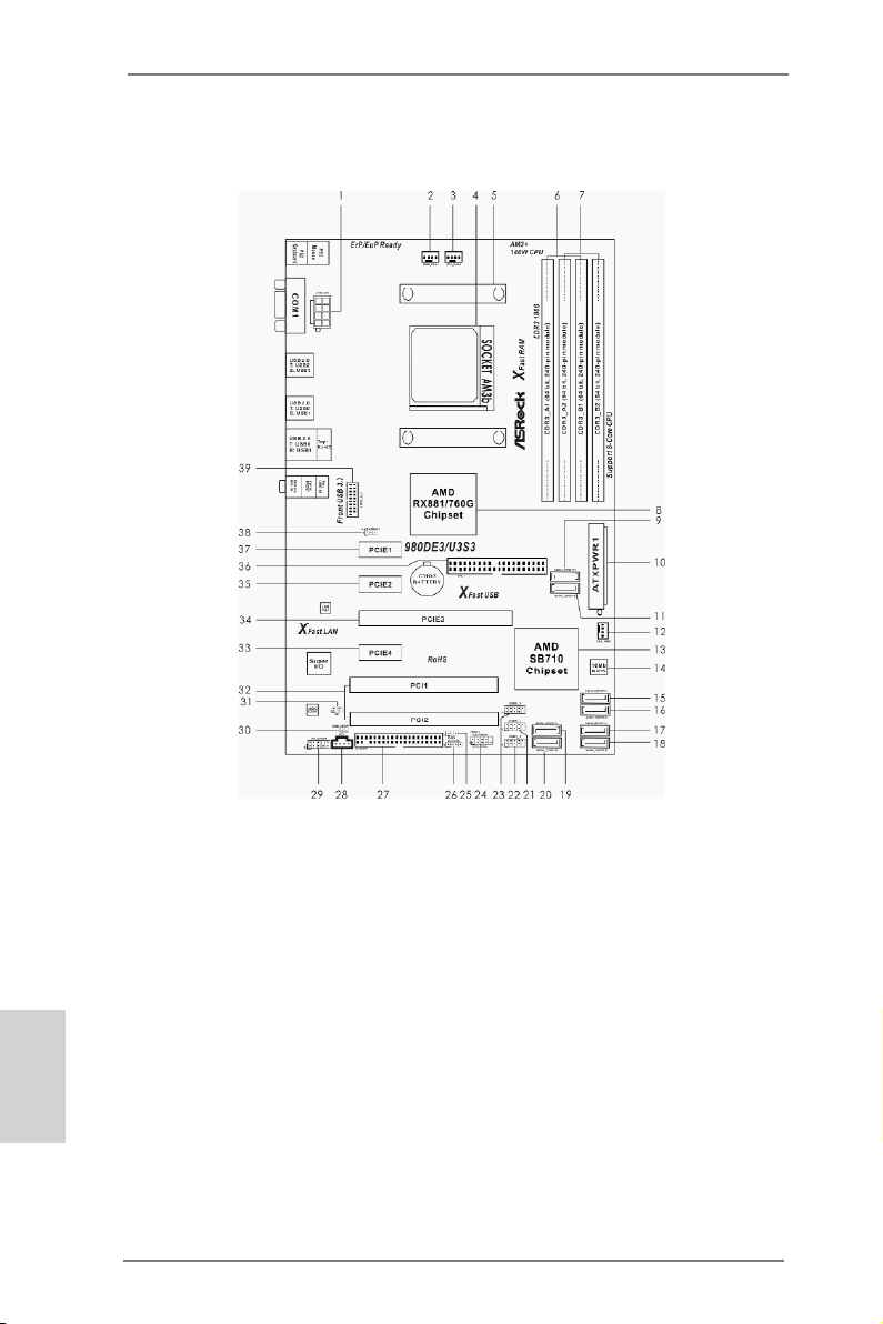
Motherboard Layout
English
2
1 ATX 12V Power Connector (ATX12V1) 20 SATA2 Connector (SATA2_1 (PORT 1))
2 Power Fan Connector (PWR_FAN1) 21 USB 2.0 Header (USB6_7)
3 CPU Fan Connector (CPU_FAN1) 22 USB 2.0 Header (USB4_5)
4 AM3+ CPU Socket 23 USB 2.0 Header (USB8_9)
5 CPU Heatsink Retention Module 24 System Panel Header (PANEL1)
6 2 x 240-pin DDR3 DIMM Slots 25 Power LED Header (PLED1)
(Dual Channel: DDR3_A1, DDR3_B1) 26 Chassis Speaker Header (SPEAKER1)
7 2 x 240-pin DDR3 DIMM Slots 27 Floppy Connector (FLOPPY1)
(Dual Channel: DDR3_A2, DDR3_B2) 28 Internal Audio Connector (CD1)
8 Northbridge Controller 29 Front Panel Audio Header (HD_AUDIO1)
9 SATA3 Connector (SATA3_2 (PORT 7)) 30 HDMI_SPDIF Header (HDMI_SPDIF1)
10 ATX Power Connector (ATXPWR1) 31 Infrared Module Header (IR1)
11 SATA3 Connector (SATA3_1 (PORT 6)) 32 PCI Slots (PCI1-2)
12 Chassis Fan Connector (CHA_FAN1) 33 PCI Express 2.0 x1 Slot (PCIE4)
13 Southbridge Controller 34 PCI Express 2.0 x16 Slot (PCIE3)
14 SPI Flash Memory (16Mb) 35 PCI Express 2.0 x1 Slot (PCIE2)
15 SATA2 Connector (SATA2_6 (PORT 5)) 36 IDE1 Connector (IDE1)
16 SATA2 Connector (SATA2_5 (PORT 4)) 37 PCI Express 2.0 x1 Slot (PCIE1)
17 SATA2 Connector (SATA2_4 (PORT 3)) 38 Clear CMOS Jumper (CLRCMOS1)
18 SATA2 Connector (SATA2_3 (PORT 2)) 39 USB 3.0 Header (USB3_2_3)
19 SATA2 Connector (SATA2_2 (PORT 1))
ASRock 980DE3/U3S3 Motherboard
Page 3
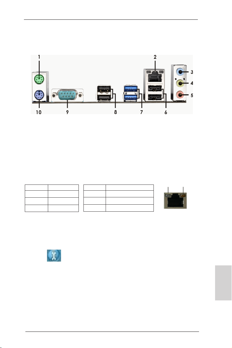
I/O Panel
1 PS/2 Mouse Port (Green) 6 USB 2.0 Ports (USB01)
* 2 LAN RJ-45 Port 7 USB 3.0 Port (USB01)
3 Line In (Light Blue) 8 USB 2.0 Ports (USB23)
** 4 Front Speaker (Lime) 9 Serial Port: COM1
5 Microphone (Pink) 10 PS/2 Keyboard Port (Purple)
* There are two LED next to the LAN port. Please refer to the table below for the LAN port LED
indications.
Activity/Link LED SPEED LED
Status Description Status Description
Off No Link Off 10Mbps connection
Blinking Data Activity Orange 100Mbps connection
On Link Green 1Gbps connection
LAN Port LED Indications
ACT/LINK
LED
LAN Port
SPEED
LED
** To enable Multi-Streaming function, you need to connect a front panel audio cable to the front
panel audio header. Please refer to below steps for the software setting of Multi-Streaming.
For Windows® XP:
After restarting your computer, you will nd “Mixer” tool on your system. Please select “Mixer
ToolBox” , click “Enable playback multi-streaming”, and click “ok”. Choose “2CH” or
“4CH” and then you are allowed to select “Realtek HDA Primary output” to use Rear Speaker
and Front Speaker, or select “Realtek HDA Audio 2nd output” to use front panel audio. Then
reboot your system.
For Windows® 8 / 7 / VistaTM:
After restarting your computer, please double-click “Realtek HD Audio Manager” on the
system tray. Set “Speaker Conguration” to “Quadraphonic” or “Stereo”. Click “Device
advanced settings”, choose “Make front and rear output devices playbacks two different audio
streams simultaneously”, and click “ok”. Then reboot your system.
ASRock 980DE3/U3S3 Motherboard
English
3
Page 4
1. Introduction
Thank you for purchasing ASRock 980DE3/U3S3 motherboard, a reliable motherboard produced under ASRock’s consistently stringent quality control. It delivers
excellent performance with robust design conforming to ASRock’s commitment to
quality and endurance.
This Quick Installation Guide contains introduction of the motherboard and step-by-
step installation guide. More detailed information of the motherboard can be found
in the user manual presented in the Support CD.
Because the motherboard specications and the BIOS software might
be updated, the content of this manual will be subject to change without
notice. In case any modications of this manual occur, the updated version will be available on ASRock website without further notice. You may
nd the latest VGA cards and CPU support lists on ASRock website as
well. ASRock website http://www.asrock.com
If you require technical support related to this motherboard, please visit
our website for specic information about the model you are using.
www.asrock.com/support/index.asp
1.1 Package Contents
ASRock 980DE3/U3S3 Motherboard (ATX Form Factor)
ASRock 980DE3/U3S3 Quick Installation Guide
ASRock 980DE3/U3S3 Support CD
2 x Serial ATA (SATA) Data Cables (Optional)
1 x I/O Panel Shield
English
4
ASRock Reminds You...
To get better performance in Windows® 8 / 8 64-bit / 7 / 7 64-bit / VistaTM
/ VistaTM 64-bit, it is recommended to set the BIOS option in Storage
Conguration to AHCI mode. For the BIOS setup, please refer to the “User
Manual” in our support CD for details.
ASRock 980DE3/U3S3 Motherboard
Page 5
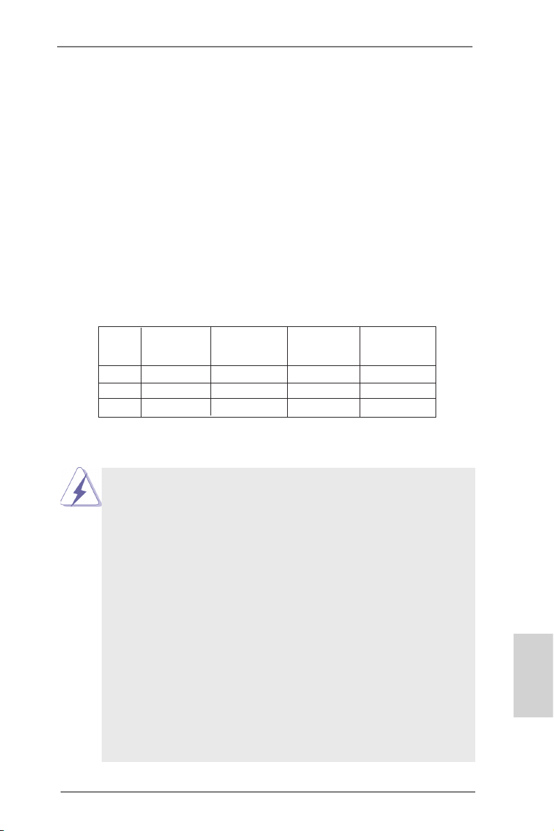
1.2 Specications
Platform - ATX Form Factor
- All Solid Capacitor design
CPU - Support for Socket AM3+ processors
- Support for Socket AM3 processors: AMD PhenomTM II X6 /
X4 / X3 / X2 (except 920 / 940) / Athlon II X4 / X3 / X2 /
Sempron processors
- Supports 8-Core CPU
- Digi Power Design
- Supports CPU up to 140W
- Supports AMD OverDriveTM with ACC feature (Advanced
Clock Calibration)
- Supports AMD’s Cool ‘n’ QuietTM Technology
- FSB 2600 MHz (5.2 GT/s)
- Supports Untied Overclocking Technology
- Supports Hyper-Transport 3.0 (HT 3.0) Technology
Chipset - Northbridge: AMD RX881/760G
- Southbridge: AMD SB710
Memory - Dual Channel DDR3 Memory Technology
- 4 x DDR3 DIMM slots
- Support DDR3 1866(OC)/1600(OC)/1333/1066/800
non-ECC, un-buffered memory (see CAUTION 1)
- Max. capacity of system memory: 32GB (see CAUTION 2)
Expansion Slot - 1 x PCI Express 2.0 x16 slot (PCIE3 @ x16 mode)
- 3 x PCI Express 2.0 x1 slots
- 2 x PCI slots
Audio - 5.1 CH HD Audio (Realtek ALC662 Audio Codec)
LAN - PCIE x1 Gigabit LAN 10/100/1000 Mb/s
- Realtek RTL8111E
- Supports Wake-On-LAN
- Supports LAN Cable Detection
- Supports Energy Efcient Ethernet 802.3az
- Supports PXE
Rear Panel I/O I/O Panel
- 1 x PS/2 Mouse Port
- 1 x PS/2 Keyboard Port
- 1 x Serial Port: COM1
- 4 x Ready-to-Use USB 2.0 Ports
- 2 x Ready-to-Use USB 3.0 Ports
English
ASRock 980DE3/U3S3 Motherboard
5
Page 6
English
- 1 x RJ-45 LAN Port with LED (ACT/LINK LED and SPEED
LED)
- HD Audio Jack: Line in / Front Speaker / Microphone
SATA3 - 2 x SATA3 6.0 Gb/s connectors by ASMedia ASM1061,
support NCQ, AHCI and Hot Plug
USB 3.0 - 2 x Rear USB 3.0 ports by Etron EJ188, support
USB 1.1/2.0/3.0 up to 5Gb/s
- 1 x Front USB 3.0 header by Etron EJ188 (supports 2
USB 3.0 ports), supports USB 1.1/2.0/3.0 up to 5Gb/s
Connector - 6 x SATA2 3.0 Gb/s connectors, support RAID (RAID 0,
RAID 1, RAID 10 and JBOD), NCQ, AHCI and “Hot Plug”
functions
- 2 x SATA3 6.0Gb/s connectors
- 1 x ATA133 IDE connector (supports 2 x IDE devices)
- 1 x Floppy connector
- 1 x IR header
- 1 x HDMI_SPDIF header
- 1 x Power LED header
- 1 x CPU Fan connector (4-pin)
- 1 x Chassis Fan connector (4-pin)
- 1 x Power Fan connector (4-pin)
- 24 pin ATX power connector
- 8 pin 12V power connector
- CD in header
- Front panel audio connector
- 3 x USB 2.0 headers (support 6 USB 2.0 ports)
- 1 x USB 3.0 header (supports 2 USB 3.0 ports)
BIOS Feature - 16Mb AMI Legal BIOS
- Supports “Plug and Play”
- ACPI 1.1 Compliance Wake Up Events
- Supports jumperfree
- SMBIOS 2.3.1 Support
- CPU, VCCM, NB Voltage Multi-adjustment
Support CD - Drivers, Utilities, AntiVirus Software (Trial Version),
CyberLink MediaEspresso 6.5 Trial, Google Chrome
Browser and Toolbar
Hardware - CPU Temperature Sensing
Monitor - Chassis Temperature Sensing
- CPU/Chassis/Power Fan Tachometer
- CPU Quiet Fan
6
ASRock 980DE3/U3S3 Motherboard
Page 7
- CPU/Chassis/Power Fan Multi-Speed Control
- Voltage Monitoring: +12V, +5V, +3.3V, Vcore
OS - Microsoft® Windows® 8 / 8 64-bit / 7 / 7 64-bit / Vista
VistaTM 64-bit / XP / XP Media Center / XP 64-bit compliant
Certications - FCC, CE, WHQL
- ErP/EuP Ready (ErP/EuP ready power supply is required)
* For detailed product information, please visit our website: http://www.asrock.com
WARNING
Please realize that there is a certain risk involved with overclocking,
including adjusting the setting in the BIOS, applying Untied Overclocking
Technology, or using third-party overclocking tools. Overclocking may
affect your system’s stability, or even cause damage to the components
and devices of your system. It should be done at your own risk and
expense. We are not responsible for possible damage caused by
overclocking.
TM
/
CAUTION!
1. Whether 1866/1600MHz memory speed is supported depends
on the AM3/AM3+ CPU you adopt. If you want to adopt DDR3
1866/1600 memory module on this motherboard, please refer
to the memory support list on our website for the compatible
memory modules.
ASRock website: http://www.asrock.com
2. Due to the operating system limitation, the actual memory size
may be less than 4GB for the reservation for system usage under Windows® 8 / 7 / VistaTM / XP. For Windows® 64-bit OS with
64-bit CPU, there is no such limitation.
ASRock 980DE3/U3S3 Motherboard
English
7
Page 8

1.3 Unique Features
ASRock OC Tuner
ASRock OC Tuner is a user-friendly overclocking tool which al-
lows you to surveil your system by hardware monitor function
and overclock your hardware devices to get the best system
performance under Windows® environment. Please visit our
website for the operation procedures of ASRock OC Tuner.
ASRock Intelligent Energy Saver
Featuring an advanced proprietary hardware and software de-
sign, Intelligent Energy Saver is a revolutionary technology that
delivers unparalleled power savings. The voltage regulator can
reduce the number of output phases to improve efciency when
the CPU cores are idle. In other words, it is able to provide exceptional power saving and improve power efficiency without
sacrificing computing performance. To use Intelligent Energy
Saver function, please enable Cool ‘n’ Quiet option in the BIOS
setup in advance. Please visit our website for the operation procedures of Intelligent Energy Saver.
ASRock Instant Boot
ASRock Instant Boot allows you to turn on your PC in just a few
seconds, provides a much more efcient way to save energy,
time, money, and improves system running speed for your system. It leverages the S3 and S4 ACPI features which normally
enable the Sleep/Standby and Hibernation modes in Windows®
to shorten boot up time. By calling S3 and S4 at specic timing
during the shutdown and startup process, Instant Boot allows
you to enter your Windows® desktop in a few seconds.
English
8
ASRock Instant Flash
ASRock Instant Flash is a BIOS ash utility embedded in Flash
ROM. This convenient BIOS update tool allows you to update
system BIOS without entering operating systems rst like MS-
DOS or Windows®. With this utility, you can press the <F6> key
during the POST or the <F2> key to enter into the BIOS setup
menu to access ASRock Instant Flash. Just launch this tool and
save the new BIOS le to your USB ash drive, oppy disk or
hard drive, then you can update your BIOS only in a few clicks
without preparing an additional oppy diskette or other
ASRock 980DE3/U3S3 Motherboard
Page 9

complicated flash utility. Please be noted that the USB flash
drive or hard drive must use FAT32/16/12 le system.
ASRock OC DNA
The software name itself – OC DNA literally tells you what it is
capable of. OC DNA, an exclusive utility developed by ASRock,
provides a convenient way for the user to record the OC settings and share with others. It helps you to save your overclocking record under the operating system and simplies the complicated recording process of overclocking settings. With OC DNA,
you can save your OC settings as a prole and share with your
friends! Your friends then can load the OC prole to their own
system to get the same OC settings as yours! Please be noticed
that the OC prole can only be shared and worked on the same
motherboard.
ASRock APP Charger
If you desire a faster, less restricted way of charging your
Apple devices, such as iPhone/iPad/iPod Touch, ASRock has
prepared a wonderful solution for you - ASRock APP Charger.
Simply install the APP Charger driver, it makes your iPhone
charge much quickly from your computer and up to 40% faster
than before. ASRock APP Charger allows you to quickly charge
many Apple devices simultaneously and even supports continuous charging when your PC enters into Standby mode (S1),
Suspend to RAM (S3), hibernation mode (S4) or power off (S5).
With APP Charger driver installed, you can easily enjoy the marvelous charging experience.
ASRock XFast USB
ASRock XFast USB can boost USB storage device perfor-
mance. The performance may depend on the properties of the
device.
ASRock XFast LAN
ASRock XFast LAN provides a faster internet access, which
includes the benefits listed below. LAN Application Prioritiza-
tion: You can congure your application’s priority ideally and/or
add new programs. Lower Latency in Game: After setting online
game’s priority higher, it can lower the latency in games. Trafc
Shaping: You can watch Youtube HD videos and download
ASRock 980DE3/U3S3 Motherboard
English
9
Page 10

simultaneously. Real-Time Analysis of Your Data: With the sta-
tus window, you can easily recognize which data streams you
are transferring currently.
ASRock XFast RAM
ASRock XFast RAM fully utilizes the memory space that cannot
be used under Windows® OS 32-bit CPU. ASRock XFast RAM
shortens the loading time of previously visited websites, mak-
ing web surng faster than ever. And it also boosts the speed of
Adobe Photoshop 5 times faster. Another advantage of ASRock
XFast RAM is that it reduces the frequency of accessing your
SSDs or HDDs in order to extend their lifespan.
ASRock X-Boost
ASRock’s X-Boost Technology is a smart auto-overclocking
function and is brilliantly designed to unlock the hidden power of
your CPUs. Simply press “X” when turning on the PC, X-Boost
will automatically overclock the relative components to get up to
15.77% performance boost! With the smart X-Boost, overclocking CPU can become a near one-button process.
* The functionality of “Unlock CPU Cores” feature might vary by
different processors.
English
10
ASRock 980DE3/U3S3 Motherboard
Page 11
2. Installation
This is an ATX form factor motherboard. Before you install the motherboard, study
the conguration of your chassis to ensure that the motherboard ts into it.
Pre-installation Precautions
Take note of the following precautions before you install motherboard
components or change any motherboard settings.
Before you install or remove any component, ensure that the
power is switched off or the power cord is detached from the
power supply. Failure to do so may cause severe damage to
the motherboard, peripherals, and/or components.
1. Unplug the power cord from the wall socket before touching any
component.
2. To avoid damaging the motherboard components due to static electricity, NEVER place your motherboard directly on the carpet or the
like. Also remember to use a grounded wrist strap or touch a safety
grounded object before you handle components.
3. Hold components by the edges and do not touch the ICs.
4. Whenever you uninstall any component, place it on a grounded
anti-static pad or in the bag that comes with the component.
5. When placing screws into the screw holes to secure the motherboard to the chassis, please do not over-tighten the screws! Doing
so may damage the motherboard.
ASRock 980DE3/U3S3 Motherboard
English
11
Page 12
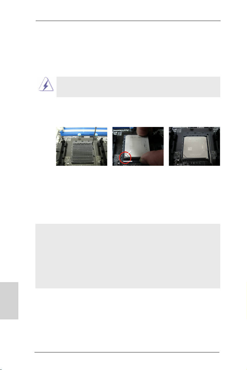
2.1 CPU Installation
Step 1. Unlock the socket by lifting the lever up to a 90
o
angle.
Step 2. Position the CPU directly above the socket such that the CPU corner with
the golden triangle matches the socket corner with a small triangle.
Step 3. Carefully insert the CPU into the socket until it ts in place.
The CPU ts only in one correct orientation. DO NOT force the CPU
into the socket to avoid bending of the pins.
Step 4. When the CPU is in place, press it rmly on the socket while you push
down the socket lever to secure the CPU. The lever clicks on the side tab
to indicate that it is locked.
Lever 90° Up
CPU Golden Triangle
STEP 1:
Lift Up The Socket Lever
STEP 2 / STEP 3:
Match The CPU Golden Triangle
To The Socket Corner Small
Triangle
Socker Corner
Small Triangle
STEP 4:
Push Down And Lock
The Socket Lever
2.2 Installation of CPU Fan and Heatsink
English
12
After you install the CPU into this motherboard, it is necessary to install a
larger heatsink and cooling fan to dissipate heat. You also need to spray
thermal grease between the CPU and the heatsink to improve heat dissipation. Make sure that the CPU and the heatsink are securely fastened
and in good contact with each other. Then connect the CPU fan to the
CPU FAN connector (CPU_FAN1, see Page 2, No. 3). For proper installation, please kindly refer to the instruction manuals of the CPU fan and
the heatsink.
ASRock 980DE3/U3S3 Motherboard
Page 13
2.3 Installation of Memory Modules (DIMM)
This motherboard provides four 240-pin DDR3 (Double Data Rate 3) DIMM slots,
and supports Dual Channel Memory Technology. For dual channel conguration,
you always need to install identical (the same brand, speed, size and chip-type)
DDR3 DIMM pair in the slots. In other words, you have to install identical DDR3
DIMM pair in Dual Channel (DDR3_A1 and DDR3_B1; Black slots; see p.2 No.6)
or identical DDR3 DIMM pair in Dual Channel (DDR3_A2 and DDR3_B2; Black
slots; see p.2 No.7), so that Dual Channel Memory Technology can be activated.
This motherboard also allows you to install four DDR3 DIMMs for dual channel
conguration, and please install identical DDR3 DIMMs in all four slots. You may
refer to the Dual Channel Memory Conguration Table below.
Dual Channel Memory Congurations
DDR3_A1 DDR3_A2 DDR3_B1 DDR3_B2
(Black Slot) (Black Slot) (Black Slot) (Black Slot)
(1) Populated - Populated (2) - Populated - Populated
(3)* Populated Populated Populated Populated
For the conguration (3), please install identical DDR3 DIMMs in all four
*
slots.
1. Please install the memory module into the slots DDR3_A2 and
DDR3_B2 for the rst priority.
2. If you want to install two memory modules, for optimal compatibility
and reliability, it is recommended to install them either in the set of
slots DDR3_A1 and DDR3_B1, or in the set of slots DDR3_A2 and
DDR3_B2.
3. If only one memory module or three memory modules are installed
in the DDR3 DIMM slots on this motherboard, it is unable to activate
the Dual Channel Memory Technology.
4. If a pair of memory modules is NOT installed in the same Dual
Channel, for example, installing a pair of memory modules in
DDR3_A1 and DDR3_A2, it is unable to activate the Dual Channel
Memory Technology .
5. It is not allowed to install a DDR or DDR2 memory module into
DDR3 slot; otherwise, this motherboard and DIMM may be damaged.
6. If you adopt DDR3 1866/1600 memory modules on this motherboard, it is recommended to install them on DDR3_A2 and DDR3_
B2 slots.
English
ASRock 980DE3/U3S3 Motherboard
13
Page 14
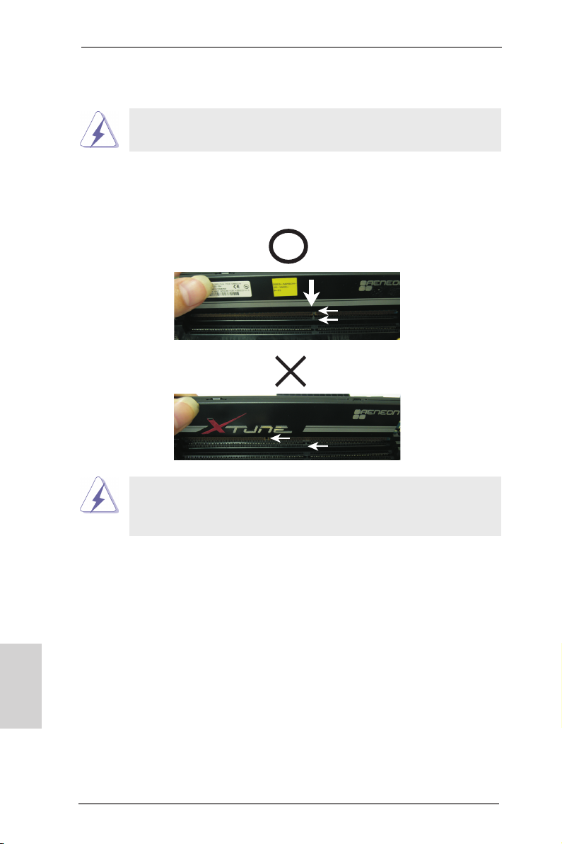
Installing a DIMM
Please make sure to disconnect power supply before adding or
removing DIMMs or the system components.
Step 1. Unlock a DIMM slot by pressing the retaining clips outward.
Step 2. Align a DIMM on the slot such that the notch on the DIMM matches the
break on the slot.
no tch
br eak
no tch
br eak
The DIMM only ts in one correct orientation. It will cause permanent
damage to the motherboard and the DIMM if you force the DIMM into
the slot at incorrect orientation.
English
14
Step 3. Firmly insert the DIMM into the slot until the retaining clips at both ends
fully snap back in place and the DIMM is properly seated.
ASRock 980DE3/U3S3 Motherboard
Page 15

2.4 Expansion Slots (PCI and PCI Express Slots)
There are 2 PCI slots and 4 PCI Express slots on this motherboard.
PCI Slots: PCI slots are used to install expansion cards that have the 32-bit PCI
interface.
PCIE Slots:
PCIE1 / PCIE2 / PCIE4 (PCIE x1 slot; Black) is used for PCI Express
cards with x1 lane width cards, such as Gigabit LAN card and SATA2
card.
PCIE3 (PCIE x16 slot; Black) is used for PCI Express x16 lane width
graphics cards.
Installing an expansion card
Step 1. Before installing the expansion card, please make sure that the power
supply is switched off or the power cord is unplugged. Please read the
documentation of the expansion card and make necessary hardware
settings for the card before you start the installation.
Step 2. Remove the system unit cover (if your motherboard is already installed
in a chassis).
Step 3. Remove the bracket facing the slot that you intend to use. Keep the
screws for later use.
Step 4. Align the card connector with the slot and press rmly until the card is
completely seated on the slot.
Step 5. Fasten the card to the chassis with screws.
Step 6. Replace the system cover.
ASRock 980DE3/U3S3 Motherboard
English
15
Page 16
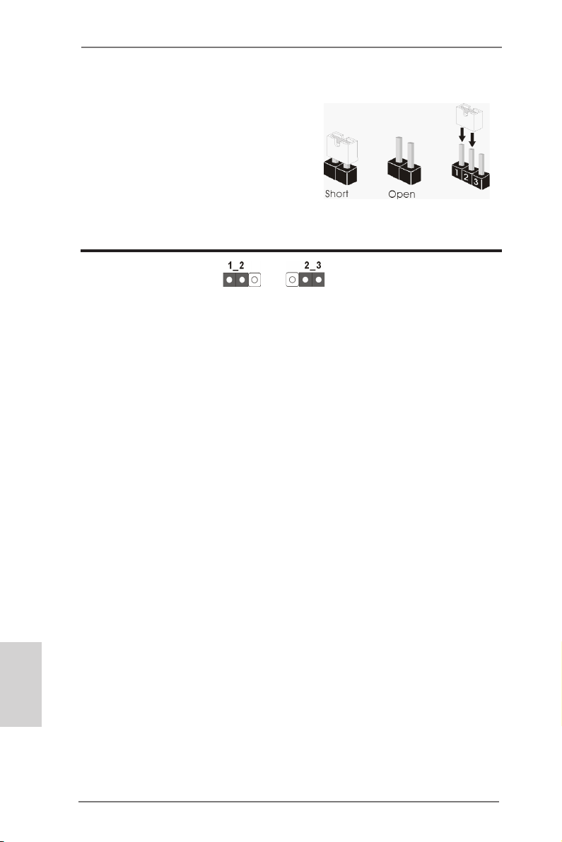
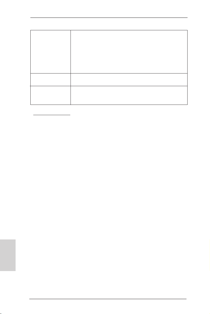
2.5 Jumpers Setup
The illustration shows how jumpers are
setup. When the jumper cap is placed on
pins, the jumper is “Short”. If no jumper cap
is placed on pins, the jumper is “Open”. The
illustration shows a 3-pin jumper whose
pin1 and pin2 are “Short” when jumper cap
is placed on these 2 pins.
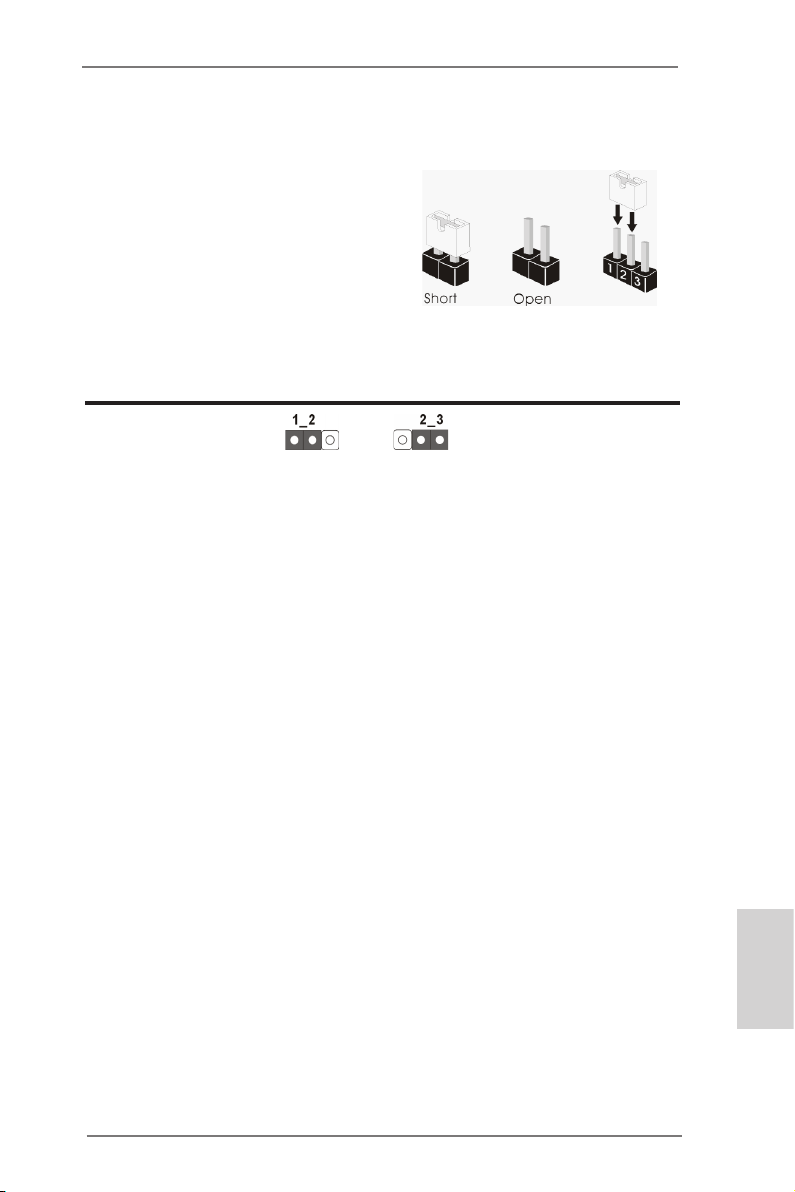
Jumper Setting Description
Clear CMOS Jumper
(CLRCMOS1)
(see p.2, No. 38)
Note: CLRCMOS1 allows you to clear the data in CMOS. To clear and reset the
system parameters to default setup, please turn off the computer and unplug
the power cord from the power supply. After waiting for 15 seconds, use a
jumper cap to short pin2 and pin3 on CLRCMOS1 for 5 seconds. However,
please do not clear the CMOS right after you update the BIOS. If you need
to clear the CMOS when you just nish updating the BIOS, you must boot
up the system rst, and then shut it down before you do the clear-CMOS action. Please be noted that the password, date, time, user default prole, 1394
GUID and MAC address will be cleared only if the CMOS battery is removed.
Clear CMOSDefault
English
16
ASRock 980DE3/U3S3 Motherboard
Page 17
2.6 Onboard Headers and Connectors
Onboard headers and connectors are NOT jumpers. Do NOT place
jumper caps over these headers and connectors. Placing jumper caps
over the headers and connectors will cause permanent damage of the
motherboard!
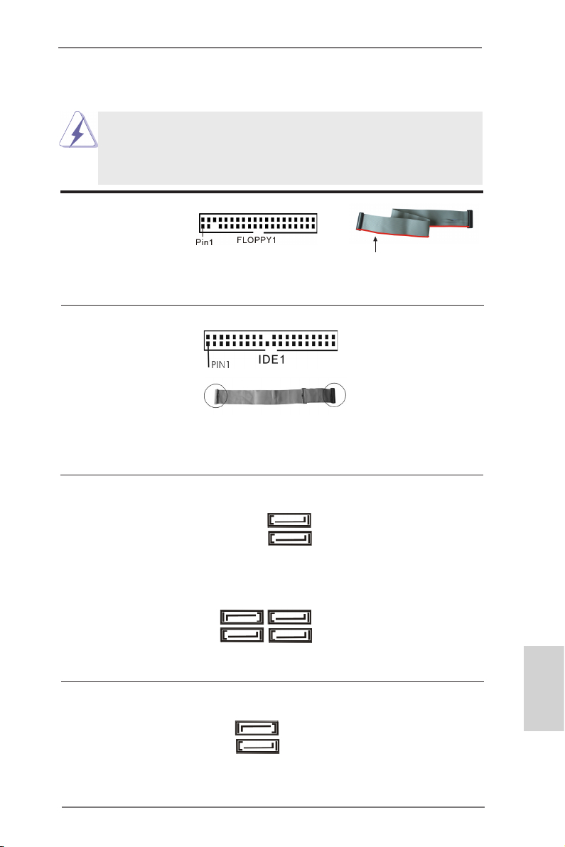
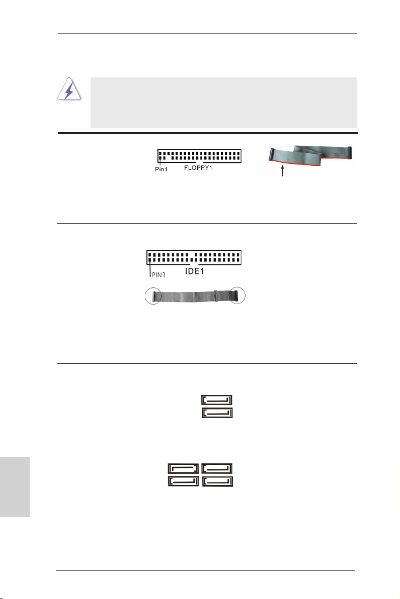
FDD connector
(33-pin FLOPPY1)
(see p.2 No. 27)
the red-striped side to Pin1
Note: Make sure the red-striped side of the cable is plugged into Pin1 side of the
connector.
Primary IDE connector (Black)
(39-pin IDE1, see p.2 No. 36)
connect the blue end
to the motherboard
connect the black end
to the IDE devices
80-conductor ATA 66/100/133 cable
Note: Please refer to the instruction of your IDE device vendor for the details.
Serial ATA2 Connectors These six Serial ATA2 (SATA2)
(SATAII_1 (PORT 0): see p.2, No. 20)
(SATAII_2 (PORT 1): see p.2, No. 19)
(SATAII_3 (PORT 2): see p.2, No. 18)
(SATAII_4 (PORT 3): see p.2, No. 17)
(SATAII_5 (PORT 4): see p.2, No. 16)
(SATAII_6 (PORT 5): see p.2, No. 15)
connectors support SATA data
cables for internal storage
devices. The current SATA2
interface allows up to 3.0 Gb/s
data transfer rate.
SATAII_2 SATAII_4
(PORT 1) (PORT 3)
SATAII_1 SATAII_3
(PORT 0) (PORT 2)
Serial ATA3 Connectors These two Serial ATA3
(SATA3_1 (PORT 6): see p.2, No. 11)
(SATA3_2 (PORT 7): see p.2, No. 9)
(SATA3) connectors support
SATA data cables for internal
SATAII_6
(PORT 5)
SATAII_5
(PORT 4)
SATA3_2
(PORT 7)
storage devices. The current
SATA3 interface allows up to
6.0 Gb/s data transfer rate.
SATA3_1
(PORT 6)
English
ASRock 980DE3/U3S3 Motherboard
17
Page 18
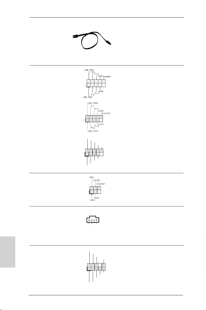
Serial ATA (SATA) Either end of the SATA data
CD- L
GND
GND
CD- R
Data Cable cable can be connected to the
(Optional)
SATA / SATA2 / SATA3 hard
disk or the SATA3 connector on
this motherboard.
USB 2.0 Headers Besides four default USB 2.0
(9-pin USB4_5)
(see p.2 No. 22)
ports on the I/O panel, there
are three USB 2.0 headers on
this motherboard. Each USB 2.0
header can support two USB
2.0 ports.
(9-pin USB6_7)
(see p.2 No. 21)
English
1
USB _PWR
P-9
P-8
USB _PWR
P+9
P+8
GND
GND
DUM MY
(9-pin USB8_9)
(see p.2 No. 23)
Infrared Module Header This header supports an
(5-pin IR1)
optional wireless transmitting
(see p.2 No. 31)
and receiving infrared module.
Internal Audio Connectors This connector allows you to
(4-pin CD1)
(CD1: see p.2 No. 28)
receive stereo audio input from
CD1
sound sources such as a
CD-ROM, DVD-ROM, TV tuner
card, or MPEG card.
Front Panel Audio Header This is an interface for the front
(9-pin HD_AUDIO1)
(see p.2 No. 29)
panel audio cable that allows
convenient connection and
control of audio devices.
1
GND
PRE SENC E#
MIC 2_R
MIC 2_L
MIC _RET
J_S ENSE
OUT 2_R
OUT _RET
OUT 2_L
18
ASRock 980DE3/U3S3 Motherboard
Page 19
1. High Denition Audio supports Jack Sensing, but the panel wire on
the chassis must support HDA to function correctly. Please follow the
instruction in our manual and chassis manual to install your system.
2. If you use AC’97 audio panel, please install it to the front panel audio
header as below:
A. Connect Mic_IN (MIC) to MIC2_L.
B. Connect Audio_R (RIN) to OUT2_R and Audio_L (LIN) to OUT2_L.
C. Connect Ground (GND) to Ground (GND).
D. MIC_RET and OUT_RET are for HD audio panel only. You don’t
need to connect them for AC’97 audio panel.
E. To activate the front mic.
For Windows® XP / XP 64-bit OS:
Select “Mixer”. Select “Recorder”. Then click “FrontMic”.
For Windows® 8 / 8 64-bit / 7 / 7 64-bit / VistaTM / VistaTM 64-bit OS:
Go to the "FrontMic" Tab in the Realtek Control panel. Adjust
“Recording Volume”.
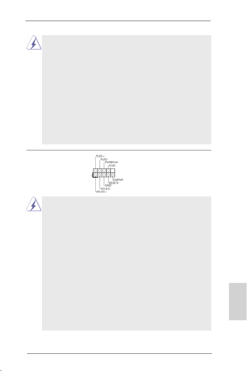
System Panel Header This header accommodates
(9-pin PANEL1)
(see p.2 No. 24)
several system front panel
functions.
Connect the power switch, reset switch and system status indicator
on the chassis to this header according to the pin assignments below.
Note the positive and negative pins before connecting the cables.
PWRBTN (Power Switch):
Connect to the power switch on the chassis front panel. You may con-
gure the way to turn off your system using the power switch.
RESET (Reset Switch):
Connect to the reset switch on the chassis front panel. Press the reset
switch to restart the computer if the computer freezes and fails to perform a normal restart.
PLED (System Power LED):
Connect to the power status indicator on the chassis front panel. The
LED is on when the system is operating. The LED keeps blinking
when the sys-tem is in S1 sleep state. The LED is off when the system
is in S3/S4 sleep state or powered off (S5).
HDLED (Hard Drive Activity LED):
Connect to the hard drive activity LED on the chassis front panel. The
LED is on when the hard drive is reading or writing data.
ASRock 980DE3/U3S3 Motherboard
English
19
Page 20
The front panel design may differ by chassis. A front panel module
mainly consists of power switch, reset switch, power LED, hard drive
activity LED, speaker and etc. When connecting your chassis front
panel module to this header, make sure the wire assignments and the
pin assign-ments are matched correctly.
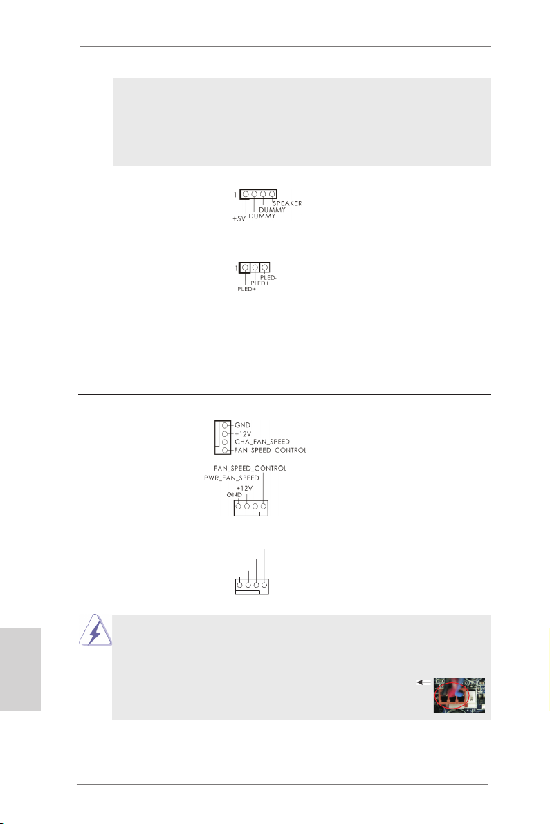
Chassis Speaker Header Please connect the chassis
(4-pin SPEAKER 1)
(see p.2 No. 26)
speaker to this header.
Power LED Header Please connect the chassis
(3-pin PLED1)
(see p.2 No. 25)
power LED to this header to
indicate system power status.
The LED is on when the system
is operating. The LED keeps
blinking in S1 state. The LED is
off in S3/S4 state or S5 state
(power off).
Chassis and Power Fan Connectors Please connect the fan cables
(4-pin CHA_FAN1)
(see p.2 No. 12)
to the fan connectors and
match the black wire to the
ground pin.
(4-pin PWR_FAN1)
(see p.2 No. 2)
English
20
CPU Fan Connectors Please connect the CPU fan
(4-pin CPU_FAN1)
(see p.2 No. 3)
cable to the connector and
match the black wire to the
ground pin.
FAN_ SPEE D_CO NTRO L
CPU _FAN_ SPEE D
+12 V
GND
1 2 3 4
Though this motherboard provides 4-Pin CPU fan (Quiet Fan) support, the 3-Pin
CPU fan still can work successfully even without the fan speed control function.
If you plan to connect the 3-Pin CPU fan to the CPU fan connector on this
motherboard, please connect it to Pin 1-3.
Pin 1-3 Connected
3-Pin Fan Installation
ASRock 980DE3/U3S3 Motherboard
Page 21
ATX Power Connector Please connect an ATX power
(24-pin ATXPWR1)
(see p.2 No. 10)
Though this motherboard provides 24-pin ATX power connector,
it can still work if you adopt a traditional 20-pin ATX power supply.
supply to this connector.
12
24
1
13
12
To use the 20-pin ATX power supply, please plug your power
supply along with Pin 1 and Pin 13.
24
20-Pin ATX Power Supply Installation
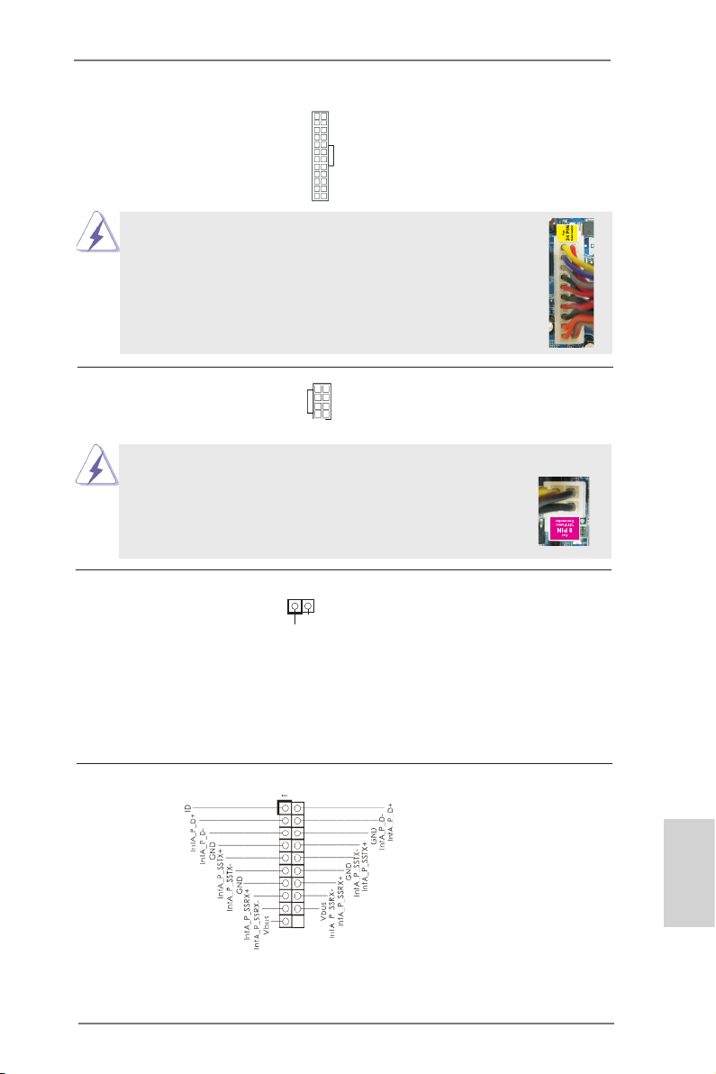
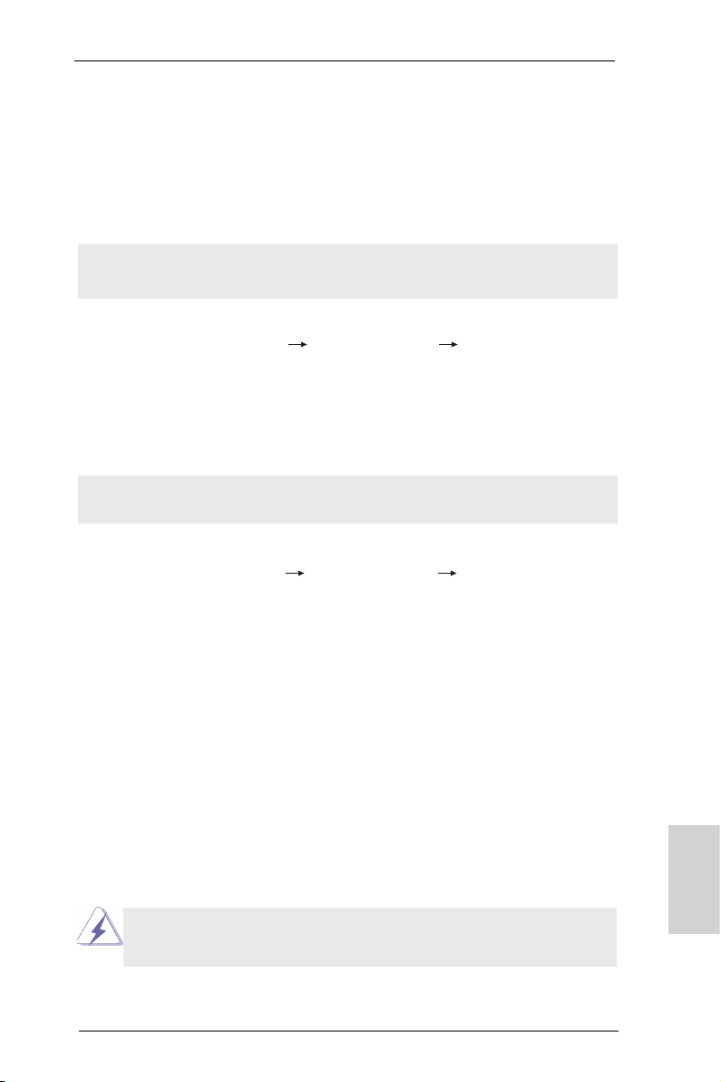
ATX 12V Power Connector Please connect an ATX 12V
(8-pin ATX12V1)
(see p.2 No. 1)
power supply to this connector.
5 1
8 4
1
13
Though this motherboard provides 8-pin ATX 12V power connector, it can still work
if you adopt a traditional 4-pin ATX 12V power supply. To use the
5 1
4-pin ATX power supply, please plug your power supply along with
Pin 1 and Pin 5.
4-Pin ATX 12V Power Supply Installation
8 4
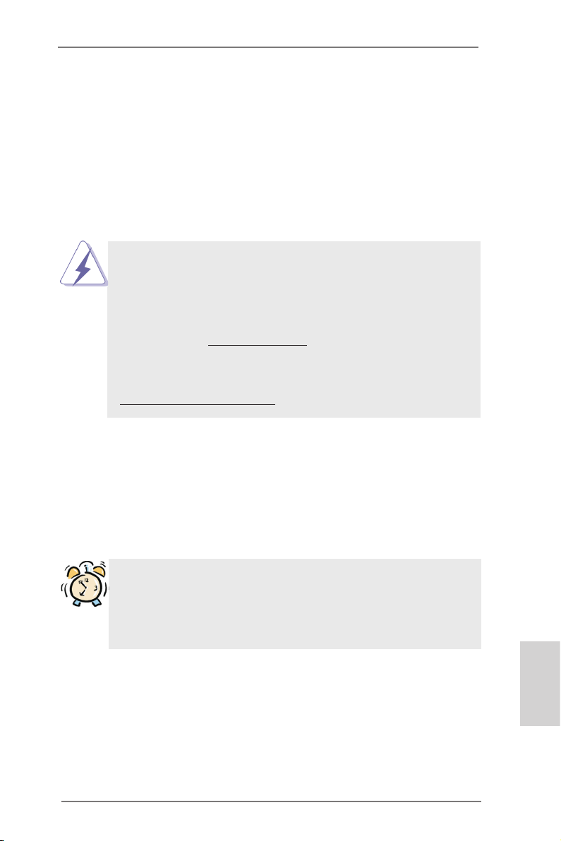
HDMI_SPDIF Header HDMI_SPDIF header, providing
(2-pin HDMI_SPDIF1)
see p.2 No. 30)
(
VGA card, allows the system to
SPDIF audio output to HDMI
1
SPD I FOUT
GND
connect HDMI Digital TV/
projector/LCD devices. Please
connect the HDMI_SPDIF
connector of HDMI VGA card to
this header.
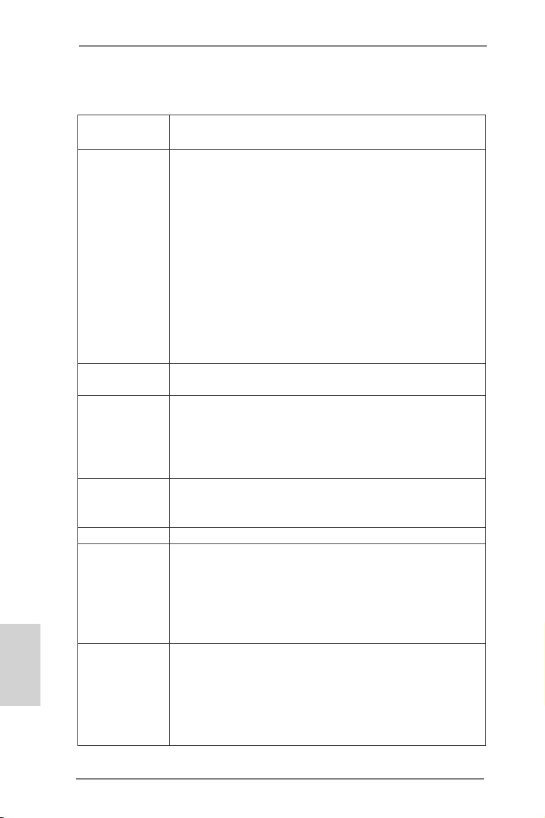
USB 3.0 Header Besides two default USB 3.0
(19-pin USB3_2_3)
(see p.2 No. 39)
ports on the I/O panel, there is
one USB 3.0 header on this
motherboard. This USB 3.0
header can support two USB 3.0
ports.
English
ASRock 980DE3/U3S3 Motherboard
21
Page 22

2.7 Driver Installation Guide
To install the drivers to your system, please insert the support CD to your optical
drive rst. Then, the drivers compatible to your system can be auto-detected and
listed on the support CD driver page. Please follow the order from up to bottom side
to install those required drivers. Therefore, the drivers you install can work properly.
2.8 Installing Windows® 8 / 8 64-bit / 7 / 7 64-bit / Vista
TM
/
VistaTM 64-bit / XP / XP 64-bit With RAID Functions
If you want to install Windows® 8 / 8 64-bit / 7 / 7 64-bit / VistaTM / VistaTM 64-bit / XP
/ XP 64-bit on your SATA / SATA2 HDDs with RAID functions, please refer to the
document at the following path in the Support CD for detailed procedures:
..\ RAID Installation Guide
2.9 Installing Windows® 8 / 8 64-bit / 7 / 7 64-bit / VistaTM /
VistaTM 64-bit / XP / XP 64-bit Without RAID Functions
If you want to install Windows® 8 / 8 64-bit / 7 / 7 64-bit / VistaTM / VistaTM 64-bit / XP
/ XP 64-bit OS on your SATA / SATA2 / SATA3 HDDs without RAID functions, please
follow below procedures according to the OS you install.
2.9.1 Installing Windows® XP / XP 64-bit Without RAID
Functions
If you want to install Windows® XP / XP 64-bit on your SATA / SATA2 / SATA3 HDDs
without RAID functions, please follow below steps.
Using SATA / SATA2 / SATA3 HDDs without NCQ and Hot Plug functions (IDE
mode)
English
22
STEP 1: Set up BIOS.
A. Enter BIOS SETUP UTILITY Advanced screen Storage Conguration.
B. Set the “SATA Operation Mode” option to [IDE] for SATA2 ports.
Set the “Onboard SATA3 Operation Mode” option to [IDE] for SATA3 ports.
STEP 2: Install Windows® XP / XP 64-bit OS on your system.
ASRock 980DE3/U3S3 Motherboard
Page 23
2.9.2 Installing Windows® 8 / 8 64-bit / 7 / 7 64-bit / VistaTM /
VistaTM 64-bit Without RAID Functions
If you want to install Windows® 8 / 8 64-bit / 7 / 7 64-bit / VistaTM / VistaTM 64-bit on
your SATA / SATA2 / SATA3 HDDs without RAID functions, please follow below
steps.
Using SATA / SATA2 / SATA3 HDDs without NCQ and Hot Plug functions (IDE
mode)
STEP 1: Set up BIOS.
A. Enter BIOS SETUP UTILITY Advanced screen Storage Conguration.
B. Set the “SATA Operation Mode” option to [IDE] for SATA2 ports.
Set the “Onboard SATA3 Operation Mode” option to [IDE] for SATA3 ports.
STEP 2: Install Windows® 8 / 8 64-bit / 7 / 7 64-bit / VistaTM / VistaTM 64-bit OS on
your system.
Using SATA / SATA2 / SATA3 HDDs with NCQ and Hot Plug functions (AHCI
mode)
STEP 1: Set up BIOS.
A. Enter BIOS SETUP UTILITY Advanced screen Storage Conguration.
B. Set the “SATA Operation Mode” option to [AHCI] for SATA2 ports.
Set the “Onboard SATA3 Operation Mode” option to [AHCI] for SATA3 ports.
STEP 2: Install Windows® 8 / 8 64-bit / 7 / 7 64-bit / VistaTM / VistaTM 64-bit OS on
your system.
2.10 Untied Overclocking Technology
This motherboard supports Untied Overclocking Technology, which means during
overclocking, FSB enjoys better margin due to xed PCI / PCIE buses. Before you
enable Untied Overclocking function, please enter “Overclock Mode” option of BIOS
setup to set the selection from [Auto] to [Manual]. Therefore, CPU FSB is untied
during overclocking, but PCI / PCIE buses are in the xed mode so that FSB can
operate under a more stable overclocking environment.
Please refer to the warning on page 7 for the possible overclocking risk
before you apply Untied Overclocking Technology.
ASRock 980DE3/U3S3 Motherboard
English
23
Page 24

3. BIOS Information
The Flash Memory on the motherboard stores BIOS Setup Utility. When you start up
the computer, please press <F2> or <Del> during the Power-On-Self-Test (POST)
to enter BIOS Setup utility; otherwise, POST continues with its test routines. If you
wish to enter BIOS Setup after POST, please restart the system by pressing <Ctl>
+ <Alt> + <Delete>, or pressing the reset button on the system chassis. The BIOS
Setup program is designed to be user-friendly. It is a menu-driven program, which
allows you to scroll through its various sub-menus and to select among the predetermined choices. For the detailed information about BIOS Setup, please refer to the
User Manual (PDF le) contained in the Support CD.
4. Software Support CD information
®
This motherboard supports various Microsoft
64-bit / 7 / 7 64-bit / VistaTM / Vista
Support CD that came with the motherboard contains necessary drivers and useful utilities that will enhance motherboard features. To begin using the Support CD,
insert the CD into your CD-ROM drive. It will display the Main Menu automatically if
“AUTORUN” is enabled in your computer. If the Main Menu does not appear auto-
matically, locate and double-click on the le “ASSETUP.EXE” from the BIN folder in
the Support CD to display the menus.
TM
64-bit / XP / XP Media Center / XP 64-bit. The
Windows® operating systems: 8 / 8
English
24
ASRock 980DE3/U3S3 Motherboard
Page 25
1. Einführung
Wir danken Ihnen für den Kauf des ASRock 980DE3/U3S3 Motherboard, ein zuver-
lässiges Produkt, welches unter den ständigen, strengen Qualitätskontrollen von
ASRock gefertigt wurde. Es bietet Ihnen exzellente Leistung und robustes Design,
gemäß der Verpflichtung von ASRock zu Qualität und Halbarkeit. Diese Schnellinstallationsanleitung führt in das Motherboard und die schrittweise Installation
ein. Details über das Motherboard nden Sie in der Bedienungsanleitung auf der
Support-CD.
Da sich Motherboard-Spezikationen und BIOS-Software verändern
können, kann der Inhalt dieses Handbuches ebenfalls jederzeit geändert
werden. Für den Fall, dass sich Änderungen an diesem Handbuch
ergeben, wird eine neue Version auf der ASRock-Website, ohne weitere
Ankündigung, verfügbar sein. Die neuesten Grakkarten und unterstützten
CPUs sind auch auf der ASRock-Website aufgelistet.
ASRock-Website: http://www.asrock.com
Wenn Sie technische Unterstützung zu Ihrem Motherboard oder spezische
Informationen zu Ihrem Modell benötigen, besuchen Sie bitte unsere
Webseite:
www.asrock.com/support/index.asp
1.1 Kartoninhalt
ASRock 980DE3/U3S3 Motherboard (ATX-Formfaktor)
ASRock 980DE3/U3S3 Schnellinstallationsanleitung
ASRock 980DE3/U3S3 Support-CD
Zwei Serial ATA (SATA) -Datenkabel (optional)
Ein I/O Shield
ASRock erinnert...
Zur besseren Leistung unter Windows® 8 / 8 64 Bit / 7 / 7 64 Bit / Vista
VistaTM 64 Bit empfehlen wir, die Speicherkonguration im BIOS auf den
AHCI-Modus einzustellen. Hinweise zu den BIOS-Einstellungen nden
Sie in der Bedienungsanleitung auf der mitgelieferten CD.
TM
ASRock 980DE3/U3S3 Motherboard
/
Deutsch
25
Page 26
Deutsch
1.2 Spezikationen
Plattform - ATX-Formfaktor
- Alle Feste Kondensatordesign
CPU - Unterstützung von Socket AM3+-Prozessoren
- Unterstützung von Socket AM3-Prozessoren: AMD
PhenomTM II X6 / X4 / X3 / X2 (außer 920 / 940) / Athlon X4 /
X3 / X2 / Sempron-Prozessor
- Acht-Kern-CPU-bereit
- Digi Power-Design
- Unterstützt CPU bis 140W
- Unterstützt AMD OverDriveTM mit ACC-Funktion (Advanced
Clock Calibration, Erweiterte Taktkalibrierung)
- Unterstützt Cool ‘n’ QuietTM-Technologie von AMD
- FSB 2600 MHz (5.2 GT/s)
- Unterstützt Untied-Übertaktungstechnologie
- Unterstützt Hyper-Transport- 3.0 Technologie (HT 3.0)
Chipsatz - Northbridge: AMD RX881/760G
- Southbridge: AMD SB710
Speicher - Unterstützung von Dual-Kanal-Speichertechnologie
- 4 x Steckplätze für DDR3
- Unterstützt DDR3 1866(OC)/1600(OC)/1333/1066/800
non-ECC, ungepufferter Speicher
- Max. Kapazität des Systemspeichers: 32GB
Erweiterungs- - 1 x PCI-Express-2.0-x16-Steckplätze (PCIE3: x16-Modus)
Steckplätze - 3 x PCI Express 2.0 x1-Steckplätze
- 2 x PCI -Steckplätze
Audio - 5.1 CH HD Audio (Realtek ALC662 Audio Codec)
LAN - PCIE x1 Gigabit LAN 10/100/1000 Mb/s
- Realtek RTL8111E
- Unterstützt Wake-On-LAN
- Unterstützt LAN-Kabelerkennung
- Unterstützt energieefzientes Ethernet 802.3az
- Unterstützt PXE
E/A-Anschlüsse I/O Panel
an der - 1 x PS/2-Mausanschluss
Rückseite - 1 x PS/2-Tastaturanschluss
- 1 x Serieller port: COM 1
- 4 x Standard-USB 2.0-Anschlüsse
- 2 x Standard-USB 3.0-Anschlüsse
26
ASRock 980DE3/U3S3 Motherboard
Page 27
- 1 x RJ-45 LAN Port mit LED (ACT/LINK LED und SPEED
LED)
- HD Audiobuchse: Audioeingang / Lautsprecher vorne /
Mikrofon
SATA3 - 2 x SATA 3-Anschlüsse (6,0 Gb/s) durch ASMedia
ASM1061; unterstützt NCQ-, AHCI-und „Hot Plug“ (Hot-
Plugging)-Funktionen
USB3.0 - 2 x USB 3.0-Ports an der Rückseite durch Etron EJ188,
unterstützt USB 1.1/2.0/3.0 mit bis zu 5 Gb/s
- 1 x USB 3.0-Header (unterstützt zwei USB 3.0-Ports) an der
Vorderseite durch Etron EJ188, unterstützt USB 1.1/2.0/3.0
mit bis zu 5 Gb/s
Anschlüsse - 6 x SATA2 3,0 GB/s-Anschlüsse, unterstützen RAID- (RAID
0, RAID 1, RAID 10 und JBOD), NCQ-, AHCI-und Hot Plug
Funktionen
- 2 x SATA3 6,0 GB/s-Anschlüsse
- 1 x ATA133 IDE-Anschlüsse (Unterstützt bis 2 IDE-Geräte)
- 1 x FDD-Anschlüsse
- 1 x Infrarot-Modul-Header
- 1 x HDMI_SPDIF-Anschluss
- 1 x Betriebs-LED-Header
- 1 x CPUlüfter-Anschluss (4-pin)
- 1 x Gehäuselüfter-Anschluss (4-pin)
- 1 x Stromlüfter-Anschluss (4-pin)
- 24-pin ATX-Netz-Header
- 8-pin anschluss für 12V-ATX-Netzteil
- Interne Audio-Anschlüsse
- Anschluss für Audio auf der Gehäusevorderseite
- 3 x USB 2.0-Anschlüsse (Unterstützung 6 zusätzlicher
USB 2.0-Anschlüsse)
- 1 x USB 3.0-Anschlüsse (Unterstützung 2 zusätzlicher
USB 3.0-Anschlüsse)
BIOS - 16Mb AMIs Legal BIOS
- Unterstützung für “Plug and Play”
- ACPI 1.1-Weckfunktionen
- JumperFree-Modus
- SMBIOS 2.3.1
- CPU, VCCM, NB Stromspannung Multianpassung
Support-CD - Treiber, Dienstprogramme, Antivirussoftware
(Probeversion), CyberLink MediaEspresso 6.5-Testversion,
Google Chrome Browser und Toolbar
Deutsch
ASRock 980DE3/U3S3 Motherboard
27
Page 28
Hardware Monitor - CPU-Temperatursensor
- Motherboardtemperaturerkennung
- Drehzahlmessung für CPU/Gehäuse/Stromlüfter
- CPU lüftergeräuschdämpfung
- Mehrstuge Geschwindigkeitsteuerung für CPU/Gehäuse/
Stromlüfter
- Spannungsüberwachung: +12V, +5V, +3.3V, Vcore
®
Betriebssysteme - Unterstützt Microsoft
VistaTM / Vista
TM
Windows® 8 / 8 64-Bit / 7 / 7 64-Bit /
64-Bit / XP / XP Media Center / XP 64-Bit
Zertizierungen - FCC, CE, WHQL
- Gemäß Ökodesign-Richtlinie (ErP/EuP) (Stromversorgung
gemäß Ökodesign-Richtlinie (ErP/EuP) erforderlich)
* Für die ausführliche Produktinformation, besuchen Sie bitte unsere Website:
http://www.asrock.com
Deutsch
28
ASRock 980DE3/U3S3 Motherboard
Page 29
1.3 Einstellung der Jumper
Die A bbildung verdeutlicht, wie Jumper
gesetzt w e r d e n . We r d e n P ins du r c h
Jumperkappen verdeckt, ist der Jumper
“gebrückt”. Werden keine Pins durch Jumperkappen verdeckt, ist der Jumper “offen”.
Die Abbildung zeigt einen 3-Pin Jumper
dessen Pin1 und Pin2 “gebrückt” sind, bzw.
es befindet sich eine Jumper-Kappe auf
diesen beiden Pins.
Jumper Einstellun
CMOS löschen
(CLRCMOS1, 3-Pin jumper)
(siehe S.2, No. 38)
DefaultEinstellung
Hinweis: CLRCMOS1 erlaubt Ihnen das Löschen der CMOS-Daten. Diese beinhal-
ten das System-Passwort, Datum, Zeit und die verschiedenen BIOS-Parameter. Um die Systemparameter zu löschen und auf die Werkseinstellung
zurückzusetzen, schalten Sie bitte den Computer ab und entfernen das
Stromkabel. Benutzen Sie eine Jumperkappe, um die
Pin 2 und Pin 3 an CLRCMOS1 für 5 Sekunden kurzzuschließen. Bitte
vergessen Sie nicht, den Jumper wieder zu entfernen, nachdem das
CMOS gelöscht wurde. Bitte vergessen Sie nicht, den Jumper wieder zu
entfernen, nachdem das CMOS gelöscht wurde. Wenn Sie den CMOSInhalt gleich nach dem Aktualisieren des BIOS löschen müssen, müssen
Sie zuerst das System starten und dann wieder ausschalten, bevor Sie
den CMOS-Inhalt löschen.
CMOS
löschen
ASRock 980DE3/U3S3 Motherboard
Deutsch
29
Page 30
1.4 Integrierte Header und Anschlüsse
Anschluss für das
Floppy-Laufwerk
(33-Pin FLOPPY1)
(siehe S.2 - No. 27)
Hinweis: Achten Sie darauf, dass die rotgestreifte Seite des Kabel mit der Stift 1-
Seite des Anschlusses verbunden wird.
Primärer IDE-Anschluss (schwarz)
(39-pin IDE1, siehe S.2 - No. 36)
Blauer Anschluss Schwarzer Anschluss
zum Motherboard zur Festplatte
80-adriges ATA 66/100/133 Kabel
Hinweis: Details entnehmen Sie bitte den Anweisungen Ihres IDE-Gerätehändlers.
Integrierte Header und Anschlüsse sind KEINE Jumper. Setzen Sie KEINE Jumperkappen auf diese Header und Anschlüsse. Wenn Sie Jumperkappen auf Header und Anschlüsse setzen, wird das Motherboard
unreparierbar beschädigt!
die rotgestreifte Seite auf Stift 1
Deutsch
30
Seriell-ATAII-Anschlüsse Diese sechs Serial ATAII-
(SATAII_1 (PORT 0): siehe S.2 - No. 20)
(SATAII_2 (PORT 1): siehe S.2 - No. 19)
(SATAII_3 (PORT 2): siehe S.2 - No. 18)
(SATAII_4 (PORT 3): siehe S.2 - No. 17)
(SATAII_5 (PORT 4): siehe S.2 - No. 16)
(SATAII_6 (PORT 5): siehe S.2 - No. 15)
Datenübertragungsrate bis
(SATAII-)Verbínder
unterstützten SATA-Datenkabel
für interne
Massenspeichergeräte. Die
aktuelle SATAII-Schnittstelle
ermöglicht eine
SATAII_2 SATAII_4
(PORT 1) (PORT 3)
SATAII_6
(PORT 5)
SATAII_5
(PORT 4)
3,0 Gb/s.
SATAII_1 SATAII_3
(PORT 0) (PORT 2)
ASRock 980DE3/U3S3 Motherboard
Page 31

Seriell-ATA3-Anschlüsse Diese zwei Serial ATA3-
(SATA3_1 (PORT 6): siehe S.2 - No. 11)
(SATA3_2 (PORT 7): siehe S.2 - No. 9)
SATA3_2
(SATA3-)Verbínder
(PORT 7)
unterstützten SATA-Datenkabel
für interne
Massenspeichergeräte. Die
aktuelle SATA3- Schnittstelle
SATA3_1
(PORT 6)
ermöglicht eine
Datenübertragungsrate bis
6,0 Gb/s.
Serial ATA- (SATA-) SJedes Ende des SATA
Datenkabel Datenkabels kann an die
(Option)
SATA / SATAII / SATA3
Festplatte oder das SATA3
Verbindungsstück auf dieser
Hauptplatine angeschlossen
werden.
USB 2.0-Header Zusätzlich zu den vier
(9-pol. USB4_5)
(siehe S.2 - No. 22)
üblichen USB 2.0-Ports an den
I/O-Anschlüssen benden sich
drei USB 2.0-
Anschlussleisten am
Motherboard. Pro USB 2.0-
(9-pol. USB6_7)
(siehe S.2 - No. 21)
Anschlussleiste werden zwei
USB 2.0-Ports unterstützt.
(9-pol. USB8_9)
(siehe S.2 - No. 23)
1
USB _PWR
P-9
P-8
USB _PWR
P+9
P+8
GND
GND
DUM MY
Infrarot-Modul-Header Dieser Header unterstützt ein
(5-pin IR1)
optionales, drahtloses Sende-
(siehe S.2 - No. 31)
und Empfangs-Infrarotmodul.
ASRock 980DE3/U3S3 Motherboard
Deutsch
31
Page 32

CD- L
GND
GND
CD- R
Interne Audio-Anschlüsse Diese ermöglichen Ihnen
(4-Pin CD1)
(siehe S.2 - No. 28)
Stereo-Signalquellen, wie z. B.
CD-ROM, DVD-ROM, TV-Tuner
CD1
oder MPEG-Karten mit Ihrem
System zu verbinden.
Anschluss für Audio auf Dieses Interface zu einem
der Gehäusevorderseite Audio-Panel auf der Vorder
(9-Pin HD_AUDIO1)
(siehe S.2 - No. 29)
seite Ihres Gehäuses,
ermöglicht Ihnen eine bequeme
Anschlussmöglichkeit und
Kontrolle über Audio-Geräte.
1
GND
PRE SENC E#
MIC 2_R
MIC 2_L
MIC _RET
J_S ENSE
OUT 2_R
OUT _RET
OUT 2_L
1. High Denition Audio unterstützt Jack Sensing (automatische Erkennung
falsch angeschlossener Geräte), wobei jedoch die Bildschirmverdrahtung
am Gehäuse HDA unterstützen muss, um richtig zu funktionieren.
Beachten Sie bei der Installation im System die Anweisungen in unserem
Handbuch und im Gehäusehandbuch.
2. Wenn Sie die AC’97-Audioleiste verwenden, installieren Sie diese wie
nachstehend beschrieben an der Front-Audioanschlussleiste:
A. Schließen Sie Mic_IN (MIC) an MIC2_L an.
B. Schließen Sie Audio_R (RIN) an OUT2_R und Audio_L (LIN) an OUT2_L an.
C. Schließen Sie Ground (GND) an Ground (GND) an.
D. MIC_RET und OUT_RET sind nur für den HD-Audioanschluss gedacht. Diese
Anschlüsse müssen nicht an die AC’97-Audioleiste angeschlossen werden.
E. So aktivieren Sie das Mikrofon an der Vorderseite.
Bei den Betriebssystemen Windows® XP / XP 64 Bit:
Wählen Sie „Mixer“. Wählen Sie „Recorder“ (Rekorder). Klicken Sie dann
auf „FrontMic“ (Vorderes Mikrofon).
Bei den Betriebssystemen Windows® 8 / 8 64 Bit / 7 / 7 64 Bit / VistaTM / VistaTM
64 Bit:
Wählen Sie im Realtek-Bedienfeld die „FrontMic“ (Vorderes Mikrofon)-
Registerkarte. Passen Sie die „Recording Volume“ (Aufnahmelautstärke)
an.
Deutsch
System Panel-Header Dieser Header unterstützt
(9-pin PANEL1)
(siehe S.2 - No. 24)
mehrere Funktion der
Systemvorderseite.
32
ASRock 980DE3/U3S3 Motherboard
Page 33

Schließen Sie die Ein-/Austaste, die Reset-Taste und die
Systemstatusanzeige am Gehäuse an diesen Header an; befolgen Sie
dabei die nachstehenden Hinweise zur Pinbelegung. Beachten Sie die
positiven und negativen Pins, bevor Sie die Kabel anschließen.
PWRBTN (Ein-/Ausschalter):
Zum Anschließen des Ein-/Ausschalters an der Frontblende des Gehäu
ses. Sie können kongurieren, wie das System mit Hilfe des
Ein-/Ausschalters ausgeschaltet werden können soll.
RESET (Reset-Taste):
Zum Anschließen der Reset-Taste an der Frontblende des Gehäuses.
Mit der Reset-Taste können Sie den Computer im Falle eines Absturzes
neu starten.
PLED (Systembetriebs-LED):
Zum Anschließen der Betriebsstatusanzeige an der Frontblende des
Gehäuses. Die LED leuchtet, wenn das System in Betrieb ist. Die LED
blinkt, wenn sich das System im Ruhezustand S1 bendet. Die LED
schaltet sich aus, wenn sich das System in den Modi S3/S4 bendet
oder ausgeschaltet ist (S5).
HDLED (Festplattenaktivitäts-LED):
Zum Anschließen der Festplattenaktivitäts-LED an der Frontblende des
Gehäuses. Die LED leuchtet, wenn die Festplatte Daten liest oder
schreibt.
Das Design der Frontblende kann je nach Gehäuse variiere. Ein
Frontblendenmodul besteht hauptsächlich aus einer Ein-/Austaste, einer
Reset-Taste, einer Betriebs-LED, einer Festplattenaktivitäts-LED,
Lautsprechern, etc. Stellen Sie beim Anschließen des
Frontblendenmoduls Ihres Gehäuses an diesem Header sicher, dass die
Kabel- und Pinbelegung korrekt übereinstimmen.
Gehäuselautsprecher-Header Schließen Sie den
(4-pin SPEAKER1)
(siehe S.2 - No. 26)
Gehäuselautsprecher an
diesen Header an.
Betriebs-LED-Header Bitte schließen Sie die
(3-pin PLED1)
(siehe S.2 - No. 25)
Betriebs-LED des Gehäuses
zur Anzeige des
Systembetriebsstatus an
diesem Header an. Die LED
leuchtet, wenn das System in
Betrieb ist. Die LED blinkt im
S1-Zustand. Im S3-/S4- oder
S5-Zustand (ausgeschaltet)
leuchtet die LED nicht.
ASRock 980DE3/U3S3 Motherboard
Deutsch
33
Page 34

Gehäuse- und Stromlüfteranschlüsse Verbinden Sie die Lüfterkabel
(4-pin CHA_FAN1)
(siehe S.2, No. 12)
mit den Lüfteranschlüssen,
wobei der schwarze Draht an
den Schutzleiterstift
(4-pin PWR_FAN1)
(siehe S.2 - No. 2)
angeschlossenwird.
Deutsch
CPU-Lüfteranschluss Verbinden Sie das CPU -
(4-pin CPU_FAN1)
(siehe S.2 - No. 3)
Lüfterkabel mit diesem
Anschluss und passen Sie den
schwarzen Draht dem
Erdungsstift an.
FAN_ SPEE D_CO NTRO L
CPU _FAN_ SPEE D
+12 V
GND
1 2 3 4
Obwohl dieses Motherboard einen vierpoligen CPU-Lüfteranschluss
(Quiet Fan) bietet, können auch CPU-Lüfter mit dreipoligem Anschluss
angeschlossen werden; auch ohne Geschwindigkeitsregulierung. Wenn
Sie einen dreipoligen CPU-Lüfter an den CPU-Lüferanschluss dieses
Motherboards anschließen möchten, verbinden Sie ihn bitte mit den
Pins 1 – 3.
Pins 1–3 anschließen
Lüfter mit dreipoligem Anschluss installieren
ATX-Netz-Header Verbinden Sie die ATX-
(24-pin ATXPWR1)
(siehe S.2 - No. 10)
Obwohl dieses Motherboard einen 24-pol. ATX-
Stromversorgung mit diesem
Header.
12 124
13
12
24
Stromanschluss bietet, kann es auch mit einem
modizierten traditionellen 20-pol. ATX-Netzteil
verwendet werden. Um ein 20-pol. ATX-Netzteil zu
verwenden, stecken Sie den Stecker mit Pin 1 und
Pin 13 ein.
Installation eines 20-pol. ATX-Netzteils
1
13
ATX 12V Anschluss Bitte schließen Sie an diesen
(8-pin ATX12V1)
(siehe S.2 - No. 1)
Anschluss die ATX 12V
Stromversorgung an.
5 1
8 4
34
ASRock 980DE3/U3S3 Motherboard
Page 35

Obwohl diese Hauptplatine 8-Pin ATX 12V Stromanschluss zur
Verfügung stellt, kann sie noch arbeiten, wenn Sie einen
traditionellen 4-Pin ATX 12V Energieversorgung adoptieren. Um die
4-Pin ATX Energieversorgung zu verwenden, stecken Sie bitte Ihre
Energieversorgung zusammen mit dem Pin 1 und Pin 5 ein.
5 1
Installation der 4-Pin ATX 12V Energieversorgung
8 4
HDMI_SPDIF-Anschluss Der HDMI_SPDIF-Anschluss
(2-pin HDMI_SPDIF1)
(siehe S.2 - No. 30)
VGA-Karte zur Verfügung und
stellt einen SPDIF-
Audioausgang für eine HDMI-
1
GND
SPD I FOUT
ermöglicht den Anschluss von
HDMI-Digitalgeräten wie
Fernsehgeräten, Projektoren,
LCD-Geräten an das System.
Bitte verbinden Sie den
HDMI_SPDIF-Anschluss der
HDMI-VGA-Karte mit diesem
Anschluss.
USB 3.0-Header Neben zwei Standard-USB
(19-pol. USB3_2_3)
(siehe S.2 - No. 39)
3.0-Ports am E/A-Panel
bendet sich ein USB 3.0-
Header an diesem
Motherboard. Dieser USB 3.0 Header kann zwei USB 3.0 Ports unterstützen.
ASRock 980DE3/U3S3 Motherboard
Deutsch
35
Page 36

2. BIOS-Information
Das Flash Memory dieses Motherboards speichert das Setup-Utility. Drücken Sie
<F2> oder <Del> während des POST (Power-On-Self-Test) um ins Setup zu gelangen, ansonsten werden die Testroutinen weiter abgearbeitet. Wenn Sie ins Setup
gelangen wollen, nachdem der POST durchgeführt wurde, müssen Sie das System
über die Tastenkombination <Ctrl> + <Alt> + <Delete> oder den Reset-Knopf auf
der Gehäusevorderseite, neu starten. Natürlich können Sie einen Neustart auch
durchführen, indem Sie das System kurz ab- und danach wieder anschalten.
Das Setup-Programm ist für eine bequeme Bedienung entwickelt worden. Es ist ein
menügesteuertes Programm, in dem Sie durch unterschiedliche Untermenüs scrollen und die vorab festgelegten Optionen auswählen können. Für detaillierte Informationen zum BIOS-Setup, siehe bitte das Benutzerhandbuch (PDF Datei) auf der
Support CD.
3. Software Support CD information
Dieses Motherboard unterstützt eine Reiche von Microsoft® Windows® Betriebssystemen: 8 / 8 64-Bit / 7 / 7 64-Bit / VistaTM / VistaTM 64-Bit / XP / XP Media Center / XP
64-Bit. Die Ihrem Motherboard beigefügte Support-CD enthält hilfreiche Software,
Treiber und Hilfsprogramme, mit denen Sie die Funktionen Ihres Motherboards verbessern können Legen Sie die Support-CD zunächst in Ihr CD-ROM-Laufwerk ein.
Der Willkommensbildschirm mit den Installationsmenüs der CD wird automatisch
aufgerufen, wenn Sie die “Autorun”-Funktion Ihres Systems aktiviert haben.
Erscheint der Wilkommensbildschirm nicht, so “doppelklicken” Sie bitte auf das File
ASSETUP.EXE im BIN-Verzeichnis der Support-CD, um die Menüs aufzurufen.
Das Setup-Programm soll es Ihnen so leicht wie möglich machen. Es ist menügesteuert, d.h. Sie können in den verschiedenen Untermenüs Ihre Auswahl treffen und
die Programme werden dann automatisch installiert.
Deutsch
36
ASRock 980DE3/U3S3 Motherboard
Page 37

1. Introduction
Merci pour votre achat d’une carte mère ASRock 980DE3/U3S3, une carte mère
très able produite selon les critères de qualité rigoureux de ASRock. Elle offre des
performances excellentes et une conception robuste conformément à l’engagement
d’ASRock sur la qualité et la abilité au long terme.
Ce Guide d’installation rapide présente la carte mère et constitue un guide
d’installation pas à pas. Des informations plus détaillées concernant la carte
mère pourront être trouvées dans le manuel l’utilisateur qui se trouve sur le CD
d’assistance.
Les spécications de la carte mère et le BIOS ayant pu être mis à
jour, le contenu de ce manuel est sujet à des changements sans
notication. Au cas où n’importe qu’elle modication intervenait sur ce
manuel, la version mise à jour serait disponible sur le site web
ASRock sans nouvel avis. Vous trouverez les listes de prise en
charge des cartes VGA et CPU également sur le site Web ASRock.
Site web ASRock, http://www.asrock.com
Si vous avez besoin de support technique en relation avec cette carte
mère, veuillez consulter notre site Web pour de plus amples
informations particulières au modèle que vous utilisez.
www.asrock.com/support/index.asp
1.1 Contenu du paquet
Carte mère ASRock 980DE3/U3S3 (Facteur de forme ATX)
Guide d’installation rapide ASRock 980DE3/U3S3
CD de soutien ASRock 980DE3/U3S3
Deux câbles de données de série ATA (SATA) (en option)
Un I/O Panel Shield
ASRock vous rappelle...
Pour bénécier des meilleures performances sous Windows® 8 / 8 64 bits
/ 7 / 7 64 bits / Vista
l'option BIOS dans Conguration de stockage en mode AHCI. Pour plus
de détails sur l'installation BIOS, référez-vous au "Mode d'emploi" sur
votre CD de support.
TM
/ VistaTM 64 bits, il est recommandé de paramétrer
ASRock 980DE3/U3S3 Motherboard
Français
37
Page 38

Français
1.2 Spécications
Format - Facteur de forme ATX
- Accessoires de Carte mère
CPU - Prise en charge des processeurs sur socket AM3+
- Prise en charge des processeurs sur socket AM3:
Processeur PhenomTM II X6 / X4 / X3 / X2 (sauf 920 / 940) /
Athlon II X4 / X3 / X2 / Sempron d’AMD
- Prêt pour processeurs Huit-Core
- Conception Digi Power
- Supporte les processeurs jusqu’à 140W
- Prise en charge d’AMD OverDriveTM avec fonction ACC
(Advanced Clock Calibration ou calibrage d’horloge avancé)
- Supporte la technologie Cool ‘n’ QuietTM d’AMD
- FSB 2600 MHz (5.2 GT/s)
- Prend en charge la technologie Untied Overclocking
- Prise en charge de la technologie Hyper Transport 3.0
(HT 3.0)
Chipsets - Northbridge: AMD RX881/760G
- Southbridge: AMD SB710
Mémoire - Compatible avec la Technologie de Mémoire à Canal
- 4 x slots DIMM DDR3
- Supporter DDR3 1866(OC)/1600(OC)/1333/1066/800
non-ECC, sans amortissement mémoire
- Capacité maxi de mémoire système: 32GB
Slot d’extension - 1 x slot PCI Express 2.0 x16 (PCIE3: mode x16)
- 3 x slots PCI Express 2.0 x1
- 2 x slots PCI
Audio - 5,1 CH HD Audio (Realtek ALC662 Audio Codec)
LAN - PCIE x1 Gigabit LAN 10/100/1000 Mb/s
- Realtek RTL8111E
- Supporte du Wake-On-LAN
- Prise en charge de la détection de câble LAN
- Prend en charge la norme Energy Efcient Ethernet
(Ethernet à efcacité énergétique) 802.3az
- Support de PXE
Panneau arrière I/O Panel
- 1 x port souris PS/2
- 1 x port clavier PS/2
- 1 x Port séie: COM 1
38
ASRock 980DE3/U3S3 Motherboard
Page 39

- 4 x ports USB 2.0 par défaut
- 2 x ports USB 3.0 par défaut
- 1 x port LAN RJ-45 avec LED (ACT/LED CLIGNOTANTE et
LED VITESSE)
- Prise HD Audio: Entrée Ligne / Haut-parleur frontal /
Microphone
SATA3 - 2 x connecteurs SATA3 6,0 Gb/s par ASMedia ASM1061,
prennent en charge les fonctions NCQ, AHCI et « Hot
Plug » (Branche ment à chaud)
USB 3.0 - 2 x ports USB3.0 à l’arrière par AMD Etron EJ188, prennent
en charge USB 1.1/2.0/3.0 jusqu’à 5 Gb/s
- 1 x barrette USB3.0 en façade (prend en charge 2 ports
USB 3.0) par Etron EJ188, prend en charge USB 1.1/2.0/3.0
jusqu’à 5 Gb/s
Connecteurs - 6 x connecteurs SATA2, prennent en charge un taux de
transfert de données pouvant aller jusqu’à 3.0Go/s,
supporte RAID (RAID 0, RAID 1, RAID 10 et JBOD), NCQ,
AHCI et « Hot Plug » (Branche ment à chaud)
- 2 x connecteurs SATA3, prennent en charge un taux de
transfert de données pouvant aller jusqu’à 6.0Go/s
- 1 x ATA133 IDE connecteurs
(prend en charge jusqu’à 2 périphériques IDE)
- 1 x Port Disquette
- 1 x En-tête du module infrarouge
- 1 x Connecteur HDMI_SPDIF
- 1 x LED di accensione
- 1 x Connecteur pour ventilateur de CPU (br. 4)
- 1 x Connecteur pour ventilateur de Châssis (br. 4)
- 1 x Connecteur pour ventilateur de pouvoir (br. 4)
- br. 24 connecteur d’alimentation ATX
- br. 8 connecteur d’alimentation 12V ATX
- Connecteurs audio internes
- Connecteur audio panneau avant
- 3 x En-tête USB 2.0 (prendre en charge 6 ports USB 2.0
supplémentaires)
- 1 x En-tête USB 3.0 (prendre en charge 2 ports USB 3.0
supplémentaires)
BIOS - 16Mb AMI Legal BIOS
- Support du “Plug and Play”
- Compatible pour événements de réveil ACPI 1.1
- Gestion jumperless
Français
ASRock 980DE3/U3S3 Motherboard
39
Page 40

- Support SMBIOS 2.3.1
- CPU, VCCM, NB Tension Multi-ajustement
CD d’assistance - Pilotes, utilitaires, logiciel anti-virus (Version d’essai),
CyberLink MediaEspresso 6.5 Trial, Google Chrome
Browser et Toolbar
Surveillance - Détection de la température de l’UC
système - Mesure de température de la carte mère
- Tachéomètre ventilateur processeur/châssis/pouvoir
ventilateur
- Ventilateur silencieux pour unité centrale
- Commande de ventilateur CPU/Châssis/pouvoir à plusieurs
vitesses
- Monitoring de la tension: +12V, +5V, +3.3V, Vcore
OS - Microsoft® Windows® 8 / 8 64-bit / 7 / 7 64-bit / Vista
TM
/
VistaTM 64-bit /XP / XP Media Center / XP 64-bit
Certications - FCC, CE, WHQL
- Prêt pour ErP/EuP (alimentation Prêt pour ErP/EuP requise)
* Pour de plus amples informations sur les produits, s’il vous plaît visitez notre site web:
http://www.asrock.com
Français
40
ASRock 980DE3/U3S3 Motherboard
Page 41

1.3 Réglage des cavaliers
L’illustration explique le réglage des cavaliers. Quand un capuchon est placé sur les
broches, le cavalier est « FERME ». Si au-
cun capuchon ne relie les broches,le cava-
lier est « OUVERT ». L’illustration montre un
cavalier à 3 broches dont les broches 1 et 2
sont « FERMEES » quand le capuchon est
placé sur ces 2 broches.
Le cavalier Description
Effacer la CMOS
(CLRCMOS1)
(voir p.2 g. 38)
Remarque :
Paramètres
par défaut
CLRCMOS1 vous permet d’effacer les données du CMOS. Pour effacer
et réinitialiser les paramètres du système à la conguration originale,
veuillez éteindre l’ordinateur et débrancher le cordon d’alimentation de
la prise de courant. Après 15 secondes, utilisez un couvercle de jumper
pour court-circuiter les broches pin2 et pin3 de CLRCMOS1 pendant
secondes. Veuillez cependant ne pas effacer le CMOS immédiatement
a
près avoir mis à jour le BIOS. Si vous avez besoin d’effacer le CMOS
après avoir mis à jour le BIOS, vous devez allumer en premier le
système, puis l’éteindre avant de continuer avec l’opération d’effacement
du CMOS. Veuillez noter que le mot de passe, la date, l’heure, le prol
par défaut de l’utilisateur, 1394 GUID et l’adresse MAC seront effacés
seulement si la batterie du CMOS est enlevée.
Effacer la
CMOS
5
ASRock 980DE3/U3S3 Motherboard
Français
41
Page 42

1.4 En-têtes et Connecteurs sur Carte
Connecteur du lecteur
de disquette
(FLOPPY1 br. 33)
(voir p.2 No. 27)
Note: Assurez-vous que le côté avec l rouge du câble est bien branché sur le
côté Broche1 du connecteur.
Connecteur IDE primaire (noir)
(IDE1 br. 39, voir p.4 No. 8)
connecteur bleu connecteur noir
vers la carte mère vers le disque dur
Câble ATA 66/100/133 80 conducteurs
Note: Veuillez vous reporter aux instructions du fabricant de votre IDE périphérique
pour les détails.
Les en-têtes et connecteurs sur carte NE SONT PAS des cavaliers.
NE PAS placer les capuchons de cavalier sur ces en-têtes et connecteurs. Le fait de placer les capuchons de cavalier sur les en-têtes
et connecteurs causera à la carte mère des dommages irréversibles!
le côté avec l rouge côté
Broche1
Français
42
Connecteurs Série ATAII Ces six connecteurs Série
(SATAII_1 (PORT 0): voir p.2 No. 20)
(SATAII_2 (PORT 1): voir p.2 No. 19)
(SATAII_3 (PORT 2): voir p.2 No. 18)
(SATAII_4 (PORT 3): voir p.2 No. 17)
(SATAII_5 (PORT 4): voir p.2 No. 16)
(SATAII_6 (PORT 5): voir p.2 No. 15)
aller jusqu’à 3,0 Gb/s.
ATAII (SATAII) prennent en
charge les câbles SATA pour
les périphériques de stockage
internes. L’interface SATAII
actuelle permet des taux
SATAII_2 SATAII_4
transferts de données pouvant
(PORT 1) (PORT 3)
SATAII_1 SATAII_3
(PORT 0) (PORT 2)
SATAII_6
(PORT 5)
SATAII_5
(PORT 4)
ASRock 980DE3/U3S3 Motherboard
Page 43

Connecteurs Série ATA3 Ces deux connecteurs Série
(SATA3_1 (PORT 6): voir p.2 No. 11)
(SATAII_2 (PORT 7): voir p.2 No. 9)
SATA3_2
ATA3 (SATA3) prennent en
(PORT 7)
charge les câbles SATA pour
les périphériques de stockage
internes. L’interface SATA3
actuelle permet des taux
SATA3_1
(PORT 6)
transferts de données pouvant
aller jusqu’à 6,0 Gb/s.
Câble de données Toute cote du cable de data
Série ATA (SATA) SATA peut etre connecte au
(en option)
disque dur SATA / SATAII /
SATA3 ou au connecteur SATA3
sur la carte mere.
En-tête USB 2.0 A côté des quatre ports USB
(USB4_5 br.9)
(voir p.2 No. 22)
2.0 par défaut sur le panneau
E/S, il y a troi embases USB
2.0 sur cette carte mère.
Chaque embase USB 2.0 peut
prendre en charge 2 ports USB
(USB6_7 br.9)
(voir p.2 No. 21)
2.0.
1
USB _PWR
P-9
P-8
USB _PWR
P+9
P+8
GND
GND
DUM MY
(USB8_9 br.9)
(voir p.2 No. 23)
En-tête du module infrarouge Cet en-tête supporte un module
(IR1 br.5)
infrarouge optionnel de
(voir p.2 No. 31)
transfert et de réception sans
l.
ASRock 980DE3/U3S3 Motherboard
Français
43
Page 44

CD- L
GND
GND
CD- R
Connecteurs audio internes Ils vous permettent de gérer
(CD1 br. 4)
(CD1: voir p.2 No. 28)
des entrées audio à partir de
CD1
sources stéréo comme un
CD-ROM, DVD-ROM, un tuner
TV ou une carte MPEG.
1
GND
PRE SENC E#
MIC 2_R
MIC 2_L
MIC _RET
J_S ENSE
OUT 2_R
OUT _RET
OUT 2_L
Connecteur audio panneau C’est une interface pour
(HD_AUDIO1 br. 9)
(voir p.2 No. 29)
un câble avant audio en façade
qui permet le branchement et
le contrôle commodes de
périphériques audio.
1. L’audio à haute dénition (HDA) prend en charge la détection de che,
mais le l de panneau sur le châssis doit prendre en charge le HDA pour
fonctionner correctement. Veuillez suivre les instructions dans notre
manuel et le manuel de châssis an installer votre système.
2. Si vous utilisez le panneau audio AC’97, installez-le sur l’adaptateur audio
du panneau avant conformément à la procédure ci-dessous :
A. Connectez Mic_IN (MIC) à MIC2_L.
B. Connectez Audio_R (RIN) à OUT2_R et Audio_L (LIN) à OUT2_L.
C. Connectez Ground (GND) à Ground (GND).
D. MIC_RET et OUT_RET sont réservés au panneau audio HD. Vous
n’avez pas besoin de les connecter pour le panneau audio AC’97.
E. Pour activer le micro avant.
Pour les systèmes d’exploitation Windows® XP / XP 64 bits :
Sélectionnez “Mixer”. Sélectionnez “Recorder” (Enregistreur). Puis cliquez
sur “FrontMic” (Micro avant).
Pour les systèmes d’exploitation Windows® 8 / 8 64 bits / 7 / 7 64 bits / VistaTM /
VistaTM 64 bits :
Allez sur l’onglet “FrontMic” (Micro avant) sur le Panneau de contrôle
Realtek. Ajustez “Recording Volume” (Volume d’enregistrement).
Français
En-tête du panneau système Cet en-tête permet d’utiliser
(PANEL1 br.9)
(voir p.2 No. 24)
plusieurs fonctions du
panneau système frontal.
44
ASRock 980DE3/U3S3 Motherboard
Page 45

Connectez l’interrupteur d’alimentation, l’interrupteur de réinitialisation et
l’indicateur d’état du système du châssis sur cette barrette en respectant
l’affectation des broches décrite ci-dessous. Faites attention aux broches
positives et négatives avant de connecter les câbles.
PWRBTN (Interrupteur d’alimentation):
Connectez ici le connecteur d’alimentation sur le panneau avant du
châssis. Vous pouvez congurer la façon de mettre votre système hors
tension avec l’interrupteur d’alimentation.
RESET (Interrupteur de réinitialisation):
Connectez ici le connecteur de réinitialisation sur le panneau avant du
châssis. Appuyez sur l’interrupteur de réinitialisation pour redémarrer
l’ordinateur s’il se bloque ou s’il n’arrive pas à redémarrer normalement.
PLED (DEL alimentation système):
Connectez ici l’indicateur d’état de l’alimentation sur le panneau avant
du châssis. Ce voyant DEL est allumé lorsque le système est en
marche. Le voyant DEL clignote lorsque le système est en mode veille
S1. Le voyant DEL est éteint lorsque le système est en mode veille S3/
S4 ou lorsqu’il est éteint (S5).
HDLED (DEL activité du disque dur):
Connectez ici le voyant DEL d’activité du disque dur sur le panneau
avant du châssis. Ce voyant DEL est allumé lorsque le disque dur est en
train de lire ou d’écrire des données.
Le design du panneau avant peut varier en fonction du châssis. Un
module de panneau avant consiste principalement en : interrupteur
d’alimentation, interrupteur de réinitialisation, voyant DEL d’alimentation,
voyant DEL d’activité du disque dur, haut-parleur, etc. Lorsque vous
connectez le panneau avant de votre châssis sur cette barrette, vériez
bien à faire correspondre les ls et les broches.
En-tête du haut-parleur Veuillez connecter le
de châssis haut-parleur de châssis sur
(SPEAKER1 br. 4)
(voir p.2 No. 26)
cet en-tête.
LED di accensione Collegare il LED di accensione
(3-pin PLED1)
(vedi p.2 Nr. 25)
chassi per indicare lo stato di
alimentazione del sistema. Il
LED è acceso quando il sistema
è in funzione. Il LED continua a
lampeggiare in stato S1. Il LED
è spento in stato S3/S4 o S5
(spegnimento).
ASRock 980DE3/U3S3 Motherboard
Français
45
Page 46

Connecteur pour châssis et ventilateur
(CHA_FAN1 br. 4)
(voir p.2 No. 12)
(PWR_FAN1 br. 4)
(voir p.2 No. 2)
Branchez les câbles du
ventilateur aux connecteurs pour
ventilateur et faites correspondre
le l noir à la broche de terre.
Français
Connecteur du ventilateur Veuillez connecter le câble de
de l’UC ventilateur d’UC sur ce
(CPU_FAN1 br. 4)
(voir p.2 No. 3)
connecteur et brancher le l
noir sur la broche de terre.
FAN_ SPEE D_CO NTRO L
CPU _FAN_ SPEE D
+12 V
GND
1 2 3 4
Bien que cette carte mère offre un support de (Ventilateur silencieux
ventilateur de CPU à 4 broches , le ventilateur de CPU à 3 broches peut
bien fonctionner même sans la fonction de commande de vitesse du
ventilateur. Si vous prévoyez de connecter le ventilateur de CPU à 3
broches au connecteur du ventilateur de CPU sur cette carte mère,
veuillez le connecter aux broches 1-3.
Installation de ventilateur à 3 broches
Broches 1-3 connectées
En-tête d’alimentation ATX Veuillez connecter l’unité
(ATXPWR1 br. 24)
(voir p.2 No. 10)
Bien que cette carte mère fournisse un connecteur de
courant ATX 24 broches, elle peut encore fonctionner
d’alimentation ATX sur cet en-
tête.
12 124
13
12
24
si vous adopter une alimentation traditionnelle ATX 20
broches. Pour utiliser une alimentation ATX 20 broches,
branchez à l’alimentation électrique ainsi qu’aux
broches 1 et 13.
20-Installation de l’alimentation électrique ATX
1
13
Connecteur ATX 12V Veuillez connecter une unité
(ATX12V1 br.8)
(voir p.2 No. 1)
d’alimentation électrique ATX
12V sur ce connecteur.
5 1
8 4
46
ASRock 980DE3/U3S3 Motherboard
Page 47

Bien que cette carte mère possède 8 broches connecteur d’alimentation
ATX 12V, il peut toujours travailler si vous adoptez une approche
traditionnelle à 4 broches ATX 12V alimentation. Pour utiliser
l’alimentation des 4 broches ATX, branchez votre alimentation
avec la broche 1 et la broche 5.
5 1
4-Installation d’alimentation à 4 broches ATX 12V
8 4
Connecteur HDMI_SPDIF Connecteur HDMI_SPDIF,
(HDMI_SPDIF1 2-pin)
(voir p.2 No. 30)
SPDIF vers la carte VGA HDMI,
fournissant une sortie audio
1
SPD I FOUT
GND
et permettant au système
de se connecter au un
téléviseur numérique HDMI /un
projecteur / un périphérique
LCD. Veuillez brancher le
connecteur HDMI_SPDIF de la
carte VGA HDMI sur ce
connecteur.
En-tête USB 3.0 En plus des deux ports USB
(USB3_2_3 br. 19)
(voir p.2 No. 39)
3.0 par défaut sur le panneau
E/S, il y a une barrette USB 3.0
sur la carte mère. Cette barrette
USB 3.0 peut prendre en
charge deux ports USB 3.0.
ASRock 980DE3/U3S3 Motherboard
Français
47
Page 48

2. Informations sur le BIOS
La puce Flash Memory sur la carte mère stocke le Setup du BIOS. Lorsque vous
démarrez l’ordinateur, veuillez presser <F2> ou <Del> pendant le POST (Power-OnSelf-Test) pour entrer dans le BIOS; sinon, le POST continue ses tests de routine. Si
vous désirez entrer dans le BIOS après le POST, veuillez redémarrer le système en
pressant <Ctl> + <Alt> + <Suppr>, ou en pressant le bouton de reset sur le boîtier
du système. Vous pouvez également redémarrer en éteignant le système et en le
rallumant. L’utilitaire d’installation du BIOS est conçu pour être convivial. C’est un
programme piloté par menu, qui vous permet de faire déler par ses divers sousmenus et de choisir parmi les choix prédéterminés. Pour des informations détaillées
sur le BIOS, veuillez consulter le Guide de l’utilisateur (chier PDF) dans le CD
technique.
3. Informations sur le CD de support
Cette carte mère supporte divers systèmes d’exploitation Microsoft® Windows®:
8 / 8 64 bits / 7 / 7 64 bits / VistaTM / Vista
bits. Le CD technique livré avec cette carte mère contient les pilotes et les utilitaires
nécessaires pour améliorer les fonctions de la carte mère. Pour utiliser le CD technique, insérez-le dans le lecteur de CD-ROM. Le Menu principal s’afche automatiquement si “AUTORUN” est activé dans votre ordinateur. Si le Menu principal n’apparaît pas automatiquement, localisez dans le CD technique le chier “ASSETUP.
EXE” dans le dossier BIN et double-cliquez dessus pour afcher les menus.
TM
64 bits / XP / XP Media Center / XP 64
Français
48
ASRock 980DE3/U3S3 Motherboard
Page 49

1. Introduzione
Grazie per aver scelto una scheda madre ASRock 980DE3/U3S3, una scheda
madre afdabile prodotta secondo i severi criteri di qualità ASRock. Le prestazioni
eccellenti e il design robusto si conformano all’impegno di ASRock nella ricerca
della qualità e della resistenza.
Questa Guida Rapida all’Installazione contiene l’introduzione alla motherboard e la
guida passo-passo all’installazione. Informazioni più dettagliate sulla motherboard si
possono trovare nel manuale per l’utente presente nel CD di supporto.
Le speciche della scheda madre e il software del BIOS possono
essere aggiornati, pertanto il contenuto di questo manuale può subire
variazioni senza preavviso. Nel caso in cui questo manuale sia
modicato, la versione aggiornata sarà disponibile sul sito di ASRock
senza altro avviso. Sul sito ASRock si possono anche trovare le più
recenti schede VGA e gli elenchi di CPU supportate.
ASRock website http://www.asrock.com
Se si necessita dell’assistenza tecnica per questa scheda madre,
visitare il nostro sito per informazioni speciche sul modello che si
sta usando.
www.asrock.com/support/index.asp
1.1 Contenuto della confezione
Scheda madre ASRock 980DE3/U3S3 (ATX Form Factor)
Guida di installazione rapida ASRock 980DE3/U3S3
CD di supporto ASRock 980DE3/U3S3
Due cavi dati Serial ATA (SATA) (opzionali)
Un I/O Shield
ASRock vi ricorda...
Per ottenere migliori prestazioni in Windows® 8 / 8 64-bit / 7 / 7 64-bit /
TM
Vista
/ VistaTM 64-bit, si consiglia di impostare l'opzione BIOS in Storage
Conguration (Congurazione di archiviazione) sulla modalità AHCI. Per
l'impostazione BIOS, fare riferimento a “User Manual” (Manuale dell'utente) nel CD di supporto per dettagli.
ASRock 980DE3/U3S3 Motherboard
Italiano
49
Page 50

Italiano
1.2 Speciche
Piattaforma - ATX Form Factor
- Design condensatore compatto
Processore - Supporto di processori Socket AM3+
- Supporto di processori Socket AM3: AMD PhenomTM II X6 / X4
/ X3 / X2 (fatta eccezione per 920 / 940) / Athlon II X4 / X3 / X2
/ Sempron
- CPU Otto-Core Ready
- Design Digi Power
- Supporta CPU no a 140 W
- Supporta AMD OverDriveTM con funzione ACC (Advanced
Clock Calibration)
- Supporto tecnologia AMD Cool ‘n’ Quiet
- FSB 2600 MHz (5.2 GT/s)
- Supporta la tecnologia overclocking “slegata”
- Supporta la tecnologia Hyper-Transport 3.0 (HT 3.0)
Chipset - Northbridge: AMD RX881/760G
- Southbridge: AMD SB710
Memoria - Supporto tecnologia Dual Channel Memory
- 4 x slot DDR3 DIMM
- Supporto DDR3 1866(OC)/1600(OC)/1333/1066/800
non-ECC, momoria senza buffer
- Capacità massima della memoria di sistema: 32GB
Slot di - 1 x alloggiamenti PCI Express 2.0 x16 (PCIE3: modalità x16)
espansione - 3 x slot PCI Express 2.0 x1
- 2 x slot PCI
Audio - 5.1 CH HD Audio (Realtek ALC662 Audio Codec)
LAN - PCIE x1 Gigabit LAN 10/100/1000 Mb/s
- Realtek RTL8111E
- Supporta Wake-On-LAN
- Supporta il rilevamento cavo LAN
- Supporto di Energy Efcient Ethernet 802.3az
- Supporta PXE
Pannello I/O Panel
posteriore - 1 x porta PS/2 per mouse
I/O - 1 x porta PS/2 per tastiera
- 1 x Porta seriale: COM 1
- 4 x porte USB 2.0 già integrate
- 2 x porte USB 3.0 già integrate
TM
50
ASRock 980DE3/U3S3 Motherboard
Page 51

- 1 x porte LAN RJ-45 con LED (LED azione/collegamento e
LED velocità)
- Connettore HD Audio: ingresso linea / cassa frontale /
microfono
SATA3 - 2 x Connettori SATA3 6,0Gb/s ASM1061 ASMedia, supporto
delle funzioni NCQ, AHCI e “Hot Plug”
USB 3.0 - 2 x porte USB 3.0 posteriori amministrate dal controller
Etron EJ188, supporto di USB 1.1/2.0/3.0 no a 5Gb/s
- 1 x header USB 3.0 frontale (supporta 2 porte USB 3.0)
amministrato dal controller Etron EJ188, supporto di USB
1.1/2.0/3.0 no a 5Gb/s
Connettori - 6 x connettori SATA2 3.0Go/s, sopporta RAID (RAID 0, RAID 1,
RAID 10 e JBOD) e delle funzioni NCQ, AHCI e “Hot Plug”
- 2 x connettori SATA3 6.0Go/s
- 1 x connettori ATA133 IDE (supporta no a 2 dispositivi IDE)
- 1 x porta Floppy
- 1 x Collettore modulo infrarossi
- 1 x Header HDMI_SPDIF
- 1 x LED di accensione
- 1 x Connettore CPU ventola (4-pin)
- 1 x Connettore Chassis ventola (4-pin)
- 1 x Connettore Alimentazione ventola (4-pin)
- 24-pin collettore alimentazione ATX
- 8-pin connettore ATX 12V
- Connettori audio interni
- Connettore audio sul pannello frontale
- 3 x Collettore USB 2.0 (supporta 6 porte USB 2.0)
- 1 x Collettore USB 3.0 (supporta 2 porte USB 3.0)
BIOS - 16Mb AMI BIOS
- Suppor AMI legal BIOS
- Supporta “Plug and Play”
- Compatibile con ACPI 1.1 wake up events
- Supporta jumperfree
- Supporta SMBIOS 2.3.1
- Regolazione multi-voltaggio CPU, VCCM, NB
CD di - Driver, utilità, software antivirus (Versione dimostrativa),
supporto CyberLink MediaEspresso 6.5 Trial, Google Chrome
Browser e Toolbar
Italiano
ASRock 980DE3/U3S3 Motherboard
51
Page 52

Monitoraggio - Sensore per la temperatura del processore
Hardware - Sensore temperatura scheda madre
- Indicatore di velocità per la ventola del CPU/Chassis/potenza
Alimentazione
- Ventola CPU silenziosa
- Ventola CPU/Chassis/potenza con controllo di varie
velocità
- Voltaggio: +12V, +5V, +3.3V, Vcore
Compatibilità - Microsoft® Windows® 8 / 8 64 bit / 7 / 7 64 bit / VistaTM / Vista
SO
64 bit / XP / XP Media Center / XP 64 bit
Certicazioni - FCC, CE, WHQL
- Predisposto ErP/EuP (è necessaria l’alimentazione predis
posta per il sistema ErP/EuP)
* Per ulteriori informazioni, prego visitare il nostro sito internet: http://www.asrock.com
TM
Italiano
52
ASRock 980DE3/U3S3 Motherboard
Page 53

1.3 Setup dei Jumpers
L’illustrazione mostra come sono settati i jump-
er. Quando il ponticello è posizionato sui pin,
il jumper è “CORTOCIRCUITATO”. Se sui pin
non ci sono ponticelli, il jumper è “APERTO”.
L’illustrazione mostra un jumper a 3 pin in cui il
pin1 e il pin2 sono “CORTOCIRCUITATI” quando il ponticello è posizionato su questi pin.
Jumper Settaggio del Jumper
Resettare la CMOS
(CLRCMOS1)
(vedi p.2 item 38)
Nota:
CLRCMOS1 permette si azzerare i dati nella CMOS. Per cancellare e ripristinare
i
parametri del sistema sulla congurazione iniziale, spegnere il computer e
Impostazione
predenita
scollegare il cavo d’alimentazione dalla presa di corrente. Attendere 15 secondi,
poi usare un cappuccio jumper per cortocircuitare il pin 2 ed il pin 3 su
CLRCMOS1 per 5 secondi. Tuttavia, si consiglia di non cancellare la CMOS
subito dopo avere aggiornato il BIOS. Se si deve azzerare la CMOS quando si
è completato l’aggiornamento del BIOS, è necessario per prima cosa avviare
il sistema e poi spegnerlo prima di eseguire l’azzeramento della CMOS. No-
tare che password, data, ore, prolo utente predenito, 1394 GUID e indirizzo
MAC saranno cancellati solo se è rimossa la batteria della CMOS.
Azzeramen-
to CMOS
ASRock 980DE3/U3S3 Motherboard
Italiano
53
Page 54

1.4 Collettori e Connettori su Scheda
Connettore del
Floppy disk
(33-pin FLOPPY1)
(vedi p.2 Nr. 27)
Nota: Assicurarsi che il lato del cavo con la striscia rossa sia inserito nel lato Pin1
del connettore.
Connettore IDE primario (nero)
(39-pin IDE1, vedi p.2 Nr. 36)
Connettore blu Connettore nero
alla schedamadre all’hard disk drive
Cavo ATA 66/100/133 a 80 Pin
Nota: Fate riferimento alle istruzioni del produttore del dispositivo IDE per maggiori
dettagli.
I collettori ed i connettori su scheda NON sono dei jumper. NON installare cappucci per jumper su questi collettori e connettori. L’installazione
di cappucci per jumper su questi collettori e connettori provocherà
danni permanenti alla scheda madre!
Lato del Pin1 con la striscia rossa
Italiano
54
Connettori Serial ATAII Questi sei connettori Serial
(SATAII_1 (PORT 0): vedi p.2 Nr. 20)
(SATAII_2 (PORT 1): vedi p.2 Nr. 19)
(SATAII_3 (PORT 2): vedi p.2 Nr. 18)
(SATAII_4 (PORT 3): vedi p.2 Nr. 17)
(SATAII_5 (PORT 4): vedi p.2 Nr. 16)
(SATAII_6 (PORT 5): vedi p.2 Nr. 15)
attuale permette velocità di
ATAII (SATAII) supportano cavi
dati SATA per dispositivi di
immagazzinamento interni.
ATAII (SATAII) supportano cavi
SATA per dispositivi di memoria
interni. L’interfaccia SATAII
SATAII_2 SATAII_4
(PORT 1) (PORT 3)
SATAII_6
(PORT 5)
SATAII_5
(PORT 4)
trasferimento dati no a
3.0 Gb/s.
SATAII_1 SATAII_3
(PORT 0) (PORT 2)
ASRock 980DE3/U3S3 Motherboard
Page 55

Connettori Serial ATA3 Questi due connettori Serial
(SATA3_1 (PORT 6): vedi p.2 Nr. 11)
(SATA3_2 (PORT 7): vedi p.2 Nr. 9)
SATA3_2
ATA3 (SATA3) supportano cavi
(PORT 7)
dati SATA per dispositivi di
immagazzinamento interni.
ATA3 (SATA3) supportano cavi
SATA per dispositivi di memoria
SATA3_1
(PORT 6)
interni. L’interfaccia SATA3
attuale permette velocità di
trasferimento dati no a
6.0 Gb/s.
Cavi dati Serial ATA (SATA) Una o altra estremità del cavo
(Opzionale)
di dati SATA può essere
collegata al disco rigido SATA /
SATAII / SATA3 o al connettore
di SATAII / SATA3 su questa
cartolina base.
Collettore USB 2.0 Oltre alle quattro porte USB 2.0
(9-pin USB4_5)
(vedi p.2 Nr. 22)
predenite nel pannello I/O, la
scheda madre dispone di
tre intestazioni USB 2.0.
Ciascuna intestazione USB 2.0
supporta due porte USB 2.0.
(9-pin USB6_7)
(vedi p.2 Nr. 21)
(9-pin USB8_9)
(vedi p.2 Nr. 23)
1
USB _PWR
P-9
P-8
USB _PWR
P+9
P+8
GND
GND
DUM MY
Collettore modulo infrarossi Questo collettore supporta
(5-pin IR1)
moduli ad infrarossi optional
(vedi p.2 Nr. 31)
per la trasmissione e la
ricezione senza li.
ASRock 980DE3/U3S3 Motherboard
Italiano
55
Page 56

CD- L
GND
GND
CD- R
Connettori audio interni Permettono di ricevere input
(4-pin CD1)
(vedi p.2 Nr. 28)
stereo audio da fonti di
CD1
suono come CD-ROM, DVD ROM,TV tuner, o schede
MPEG.
Connettore audio sul È un’interfaccia per il cavo del
pannello frontale pannello audio. Che consente
(9-pin HD_AUDIO1)
(vedi p.2 Nr. 29)
connessione facile e controllo
dei dispositivi audio.
1
GND
PRE SENC E#
MIC 2_R
MIC 2_L
MIC _RET
J_S ENSE
OUT 2_R
OUT _RET
OUT 2_L
1. La caratteristica HDA (High Denition Audio) supporta il rilevamento dei
connettori, però il pannello dei cavi sul telaio deve supportare la funzione
HDA (High Denition Audio) per far sì che questa operi in modo corretto.
Attenersi alle istruzioni del nostro manuale e del manuale del telaio per
installare il sistema.
2. Se si utilizza un pannello audio AC’97, installarlo nell’intestazione audio
del pannello anteriore, come indicato di seguito:
A. Collegare Mic_IN (MIC) a MIC2_L.
B. Collegare Audio_R (RIN) a OUT2_R e Audio_L (LIN) ad OUT2_L.
C. Collegare Ground (GND) a Ground (GND).
D. MIC_RET e OUT_RET sono solo per il pannello audio HD. Non è
necessario collegarli per il pannello audio AC’97.
E. Per attivare il microfono frontale.
Sistema operativo Windows® XP / XP 64-bit:
Selezionare “Mixer”. Selezionare “Recorder” (Registratore). Poi, fare
clic su “FrontMic” (Microfono frontale).
Sistema operativo Windows® 8 / 8 64-bit / 7 / 7 64-bit / VistaTM / VistaTM
64-bit:
Andare alla scheda “FrontMic” (Microfono frontale) del pannello di
controllo Realtek. Regolare la voce “Recording Volume” (Volume
registrazione).
Italiano
Collettore pannello di sistema Questo collettore accomoda
(9-pin PANEL1)
(vedi p.2 Nr. 24)
diverse funzioni di sistema
pannello frontale.
56
ASRock 980DE3/U3S3 Motherboard
Page 57

Collegare l’interruttore d’alimentazione, l’interruttore di ripristino,
l’indicatore di stato del sistema del pannello frontale del telaio a questo
header in base all’assegnazione dei pin denita di seguito. Determinare i
pin positivi e negativi prima di collegare i cavi.
PWRBTN (interruttore d’alimentazione):
Va collegato all’interruttore d’alimentazione del pannello frontale del
telaio. Usando l’interruttore d’alimentazione si può congurare il modo in
cui si spegne il sistema.
RESET (interruttore di ripristino):
Va collegato all’interruttore di ripristino del pannello frontale del telaio.
Premere l’interruttore di ripristino per riavviare il sistema se il computer si
blocca e non riesce ad eseguire un normale riavvio.
PLED (LED alimentazione del sistema):
Va collegato all’indicatore di stato d’alimentazione del pannello frontale
del telaio. Il LED è acceso quando il sistema è operativo. Il LED continua
a lampeggiare quando il sistema è in stato di standby S1. Il LED è
spento quando il sistema è in stato di sospensione /ibernazione S3/S4
oppure spento (S5).
HDLED (LED attività disco rigido):
Va collegato al LED attività disco rigido del pannello frontale del telaio. Il
LED è acceso quando disco rigido legge e scrive i dati.
Il design del pannello frontale può variare in base ai telai. Il modulo di
un pannello frontale può consistere di: interruttore d’alimentazione,
interruttore di ripristino, LED d’alimentazione, LED attività disco rigido,
casse, eccetera. Quando si collega il modulo del pannello frontale a
questo header, assicurarsi che l’assegnazione dei li e dei pin sia fatta
corrispondere in modo appropriato.
Collettore casse telaio Collegare le casse del telaio a
(4-pin SPEAKER1)
(vedi p.2 Nr. 26)
questo collettore.
LED di accensione Collegare il LED di accensione
(3-pin PLED1)
(vedi p.2 Nr. 25)
chassi per indicare lo stato di
alimentazione del sistema. Il
LED è acceso quando il sistema
è in funzione. Il LED continua a
lampeggiare in stato S1. Il LED
è spento in stato S3/S4 o S5
(spegnimento).
ASRock 980DE3/U3S3 Motherboard
Italiano
57
Page 58

Collettori Chassis ed alimentazione ventola Collegare i cavi della ventola ai
(4-pin CHA_FAN1)
(vedi p.2 Nr. 12)
corrispondenti connettori
facendo combaciare il cavo
nero col pin di terra.
(4-pin PWR_FAN1)
(vedi p.2 Nr. 2)
Italiano
Connettore ventolina CPU Collegare il cavo della ventolina
(4-pin CPU_FAN1)
(vedi p.2 Nr. 3)
CPU a questo connettore e far
combaciare il lo nero al pin
terra.
FAN_ SPEE D_CO NTRO L
CPU _FAN_ SPEE D
+12 V
GND
1 2 3 4
Sebbene la presente scheda madre disponga di un supporto per ventola
CPU a 4 piedini (ventola silenziosa), la ventola CPU a 3 piedini è in
grado di funzionare anche senza la funzione di controllo della velocità
della ventola. Se si intende collegare la ventola CPU a 3 piedini al
connettore della ventola CPU su questa scheda madre, collegarla ai
piedini 1-3.
Piedini 1-3 collegati
Installazione della ventola a 3 piedini
Connettore alimentazione ATX Collegare la sorgente
(24-pin ATXPWR1)
(vedi p.2 Nr. 10)
Con questa scheda madre, c’è in dotazione un
d’alimentazione ATX a questo
connettore.
12 124
13
12
24
connettore elettrico ATX a 24 pin, ma può funzionare lo
stesso se si adotta un alimentatore ATX a 20 pin. Per
usare l’alimentatore ATX a 20 pin, collegare l’alimentatore
con il Pin 1 e il Pin 13.
Installazione dell’alimentatore ATX a 20 pin
1
13
Connettore ATX 12 V Collegare un alimentatore ATX
(8-pin ATX12V1)
(vedi p.2 Nr. 1)
12 V a questo connettore.
5 1
8 4
58
ASRock 980DE3/U3S3 Motherboard
Page 59

Sebbene questa schedamadre fornisca un connettore elettrico 8-pin ATX
12V, l‘unita‘ puo‘ ancora essere funzionante se viene utilizzata una
fornitura elettrica tradizionale a 4-pin ATX 12V. Per usare tale fornitura
elettrica 4-pin ATX 12V, prego collegare la presa elettrica
al Pin 1 e Pin 5.
5 1
Installazione elettrica 4-Pin ATX 12V
Header HDMI_SPDIF Header HDMI_SPDIF, con
(2-pin HDMI_SPDIF1)
(vedi p.2 Nr. 30)
uscita audio SPDIF su scheda
HDMI VGA, consente al
1
GND
SPD I FOUT
8 4
sistema di collegare dispositivi
per TV digitale HDMI/proiettori/
LCD . Collegare il connettore
HDMI_SPDIF della scheda
VGA HDMI a questo header.
Collettore USB 3.0 Oltre alle due porte USB 3.0
(19-pin USB3_2_3)
(vedi p.2 Nr. 39)
standard del pannello I/O,
questa scheda madre è dotata
di un header USB 3.0 che
supporta due porte USB 3.0.
ASRock 980DE3/U3S3 Motherboard
Italiano
59
Page 60

2. Informazioni sul BIOS
La Flash Memory sulla scheda madre contiene le Setup Utility. Quando si avvia il
computer, premi <F2> o <Del> durante il Power-On-Self-Test (POST) della Setup
utility del BIOS; altrimenti, POST continua con i suoi test di routine. Per entrare il
BIOS Setup dopo il POST, riavvia il sistema premendo <Ctl> + <Alt> + <Delete>, o
premi il tasto di reset sullo chassis del sistema. Per informazioni più dettagliate circa
il Setup del BIOS, fare riferimento al Manuale dell’Utente (PDF le) contenuto nel cd
di supporto.
3. Software di supporto e informazioni su
CD
Questa scheda madre supporta vari sistemi operativi Microsoft® Windows®: 8 / 8 64-
bit / 7 / 7 64-bit / VistaTM / Vista
supporto a corredo della scheda madre contiene i driver e utilità necessari a potenziare le caratteristiche della scheda.
Inserire il CD di supporto nel lettore CD-ROM. Se la funzione “AUTORUN” è attivata
nel computer, apparirà automaticamente il Menù principale. Se il Menù principale
non appare automaticamente, posizionarsi sul le “ASSETUP.EXE” nel CESTINO
del CD di supporto e cliccare due volte per visualizzare i menù.
TM
64-bit / XP / XP Media Center / XP 64-bit. Il CD di
Italiano
60
ASRock 980DE3/U3S3 Motherboard
Page 61

1. Introducción
Gracias por su compra de ASRock 980DE3/U3S3 placa madre, una placa de con-
anza producida bajo el control de calidad estricto y persistente. La placa madre
provee realización excelente con un diseño robusto conforme al compromiso de
calidad y resistencia de ASRock.
Esta Guía rápida de instalación contiene una introducción a la placa base y una
guía de instalación paso a paso. Puede encontrar una información más detallada
sobre la placa base en el manual de usuario incluido en el CD de soporte.
Porque las especicaciones de la placa madre y el software de BIOS
podrían ser actualizados, el contenido de este manual puede ser cambiado
sin aviso. En caso de cualquier modicación de este manual, la versión
actualizada estará disponible en el website de ASRock sin previo aviso.
También encontrará las listas de las últimas tarjetas VGA y CPU soportadas
en la página web de ASRock.
Website de ASRock http://www.asrock.com
Si necesita asistencia técnica en relación con esta placa base, visite
nuestra página web con el número de modelo especíco de su placa.
www.asrock.com/support/index.asp
1.1 Contenido de la caja
Placa base ASRock 980DE3/U3S3 (Factor forma ATX)
Guía de instalación rápida de ASRock 980DE3/U3S3
CD de soporte de ASRock 980DE3/U3S3
Dos cables de datos Serial ATA (SATA) (Opcional)
Una protección I/O
ASRock le recuerda...
Para mejorar el rendimiento en Windows® 8 / 8 64 bits / 7 / 7 64 bits / Vis-
TM
ta
/ VistaTM 64 bits, es recomendable establecer la opción del BIOS de
la conguración de almacenamiento en el modo AHCI. Para obtener detalles sobre la conguración del BIOS, consulte el “Manual del usuario”
que se encuentra en nuestro CD de soporte.
ASRock 980DE3/U3S3 Motherboard
Español
61
Page 62

Español
1.2 Especicación
Plataforma - Factor forma ATX
- Todo diseño de Capacitor Sólido
Procesador - Compatibilidad con procesadores con conector AM3+
- Compatibilidad con procesadores con conector AM3:
procesador AMD PhenomTM II X6 / X4 / X3 / X2 (excepto 920
/ 940) / Athlon II X4 / X3 / X2 / Sempron
- Compatible con CPU de ocho núcleo
- Diseño de alimentación digital
- Compatible con CPU de hasta 140W
- Compatible con AMD OverDriveTM con la función ACC
(Calibración Avanzada de Reloj)
- Con soporte para tecnología Cool ‘n’ QuietTM de AMD
- FSB 2600 MHz (5.2 GT/s)
- Admite tecnología de aumento de velocidad liberada
- Soporta Tecnología de Hiper-Transporte 3.0 (HT 3.0)
Chipset - North Bridge: AMD RX881/760G
- South Bridge: AMD SB710
Memoria - Soporte de Tecnología de Memoria de Doble Canal
- 4 x DDR3 DIMM slots
- Apoya DDR3 1866(OC)/1600(OC)/1333/1066/800 non-ECC,
memoria de un-buffered
- Máxima capacidad de la memoria del sistema: 32GB
Ranuras de - 1 x ranura PCI Express 2.0 x16 (PCIE3: modo x16)
Expansión - 3 x ranuras PCI Express 2.0 x1
- 2 x ranuras PCI
Audio - 5.1 CH HD Audio (Realtek ALC662 Audio Codec)
LAN - PCIE x1 Gigabit LAN 10/100/1000 Mb/s
- Realtek RTL8111E
- Soporta Wake-On-LAN
- Admite detección de conexión de cable LAN
- Compatible con Ethernet 802.3az de bajo consumo
energético
- Admite PXE
Entrada/Salida I/O Panel
de Panel - 1 x puerto de ratón PS/2
Trasero - 1 x puerto de teclado PS/2
- 1 x puerto serial: COM 1
- 4 x puertos USB 2.0 predeterminados
62
ASRock 980DE3/U3S3 Motherboard
Page 63

- 2 x puertos USB 3.0 predeterminados
- 1 x Puerto LAN RJ-45 con LED (LED de ACCIÓN/
ENLACE y LED de VELOCIDAD)
- Conexión de audio: Entrada de línea / Altavoz frontal /
Micrófono
SATA3 - 2 x conectores SATA3 de 6,0 Gb/s con chip ASMedia
ASM1061 con funciones NCQ, AHCI y de “Hot Plug”
USB 3.0 - 2 x puertos USB 3.0 traseros de Etron EJ188, compatible
con USB 1.1/2.0/3.0 de hasta 5 GB/s
- 1 x cabecera USB 3.0 delantera (compatible con 2 puertos
USB 3.0) de Etron EJ188, compatible con USB 1.1/2.0/3.0
de hasta 5 GB/s
Conectores - 6 x conexiones SATA2, admiten una velocidad de
transferencia de datos de hasta 3,0Gb/s, soporta RAID
(RAID 0, RAID 1, RAID 10 y JBOD), NCQ, AHCI y
“Conexión en caliente”
- 2 x conexiones SATA3, admiten una velocidad de
transferencia de datos de hasta 6,0Gb/s
- 1 x ATA133 conexiones IDE
(admite hasta 2 dispositivos IDE)
- 1 x puerto Floppy
- 1 x Cabezal de Módulo Infrarrojos
- 1 x cabecera HDMI_SPDIF
- 1 x cabecera de indicador LED de encendido
- 1 x Conector de ventilador de CPU (4-pin)
- 1 x Conector de ventilador de chasis (4-pin)
- 1 x Conector de ventilador de alimentacion (4-pin)
- 24-pin cabezal de alimentación ATX
- 8-pin conector de ATX 12V power
- Conector de Audio Interno
- Conector de audio de panel frontal
- 3 x Cabezal USB 2.0 (admite 6 puertos USB 2.0
adicionales)
- 1 x Cabezal USB 3.0 (admite 2 puertos USB 3.0
adicionales)
BIOS - 16Mb AMI BIOS
- AMI legal BIOS
- Soporta “Plug and Play”
- ACPI 1.1 compliance wake up events
- Soporta “jumper free setup”
- Soporta SMBIOS 2.3.1
- Múltiple ajuste de CPU, VCCM, NB Voltage
ASRock 980DE3/U3S3 Motherboard
Español
63
Page 64

CD de soport - Controladores, Utilerías, Software de Anti Virus (Versión
de prueba), Prueba de CyberLink MediaEspresso 6.5,
Google Chrome Browser y Toolbar
Monitor - Sensibilidad a la temperatura del procesador
Hardware - Sensibilidad a la temperatura de la placa madre
- Taquímetros de los ventiladores del procesador y del CPU
/ chasis / alimentación
- Ventilador silencioso del procesador
- Control de ajuste de la velocidad del ventilador de la CPU
/ chasis / alimentación
- Monitor de Voltaje: +12V, +5V, +3.3V, Vcore
OS - En conformidad con Microsoft® Windows® 8 / 8 64 bits / 7 /
7 64 bits / VistaTM / VistaTM 64 bits / XP / XP Media Center /
XP 64 bits
Certicaciones - FCC, CE, WHQL
- Cumple con la directiva ErP/EuP (se requiere una fuente
de alimentación que cumpla con la directiva ErP/EuP)
* Para más información sobre los productos, por favor visite nuestro sitio web:
http://www.asrock.com
Español
64
ASRock 980DE3/U3S3 Motherboard
Page 65

1.3 Setup de Jumpers
La ilustración muestra como los jumpers
son congurados. Cuando haya un jumper-
cap sobre los pins, se dice gue el jumper
está “Short”. No habiendo jumper cap sobre
los pins, el jumper está “Open”. La ilustración muesta un jumper de 3 pins cuyo
pin 1 y pin 2 están “Short”.
Jumper Setting
Limpiar CMOS
(CLRCMOS1, jumper de 3 pins)
(ver p.2, No. 38)
Nota:
Valor predeterminado
Restablecimiento de
la CMOS
CLRCMOS1 permite borrar los datos de la memoria CMOS. Para borrar los
parámetros del sistema y restablecer la conguración predeterminada de los mismos,
apague el equipo y desenchufe el cable de alimentación de la toma de corriente
eléctrica. Deje que transcurran 15 segundos y, después, utilice un puente
cortocircuitar los contactos 2 y 3 de CLRCMOS1 durante 5 segundos. No borre
la memoria CMOS justamente después de actualizar el BIOS. Si necesita borrar
la memoria CMOS justamente después de actualizar el BIOS, debe iniciar primero
el sistema y, a continuación, cerrarlo antes de llevar a cabo el borrado de
dicha memoria. Tenga en cuenta que la contraseña, la fecha, la hora, el perl
predeterminado del usuario, el GUID 1394 y la dirección MAC solamente se
borrará si la batería CMOS se quita.
para
ASRock 980DE3/U3S3 Motherboard
Español
65
Page 66

1.4 Cabezales y Conectores en Placas
Los conectores y cabezales en placa NO son puentes. NO coloque
las cubiertas de los puentes sobre estos cabezales y conectores. El
colocar cubiertas de puentes sobre los conectores y cabezales provocará un daño permanente en la placa base.
Conector de disquetera
(33-pin FLOPPY1)
(vea p.2, N. 27)
Atención: Asegúrese que la banda roja del cable queda situado en el mismo lado
que el contacto 1 de la conexión.
IDE conector primario (negro)
(39-pin IDE1, vea p.2, N. 36)
la banda roja debe quedar en
el mismo lado que el contacto 1
Español
66
a placa madre
Conector azul
Conector negro
a aparato IDE
Cable ATA 66/100/133 de conducción 80
Atención: Consulte las instrucciones del distribuidor del dispositivo IDE para
conocer los detalles.
Conexiones de serie ATAII Estas seis conexiones de
(SATAII_1 (PORT 0): vea p.2, N. 20)
(SATAII_2 (PORT 1): vea p.2, N. 19)
(SATAII_3 (PORT 2): vea p.2, N. 18)
(SATAII_4 (PORT 3): vea p.2, N. 17)
(SATAII_5 (PORT 4): vea p.2, N. 16)
(SATAII_6 (PORT 5): vea p.2, N. 15)
serie ATAII (SATAII) admiten
cables SATA para dispositivos
de almacenamiento internos.
La interfaz SATAII actual
permite una velocidad de
transferencia de 3.0 Gb/s.
SATAII_2 SATAII_4
(PORT 1) (PORT 3)
SATAII_1 SATAII_3
(PORT 0) (PORT 2)
SATAII_6
(PORT 5)
SATAII_5
(PORT 4)
ASRock 980DE3/U3S3 Motherboard
Page 67

Conexiones de serie ATA3 Estas dos conexiones de
(SATA3_1 (PORT 6): vea p.2, N. 11)
(SATA3_2 (PORT 7): vea p.2, N. 9)
cables SATA para dispositivos
SATA3_2
serie ATA3 (SATA3) admiten
(PORT 7)
de almacenamiento internos. La
interfaz SATAII / SATA3 actual
permite una velocidad de
SATA3_1
(PORT 6)
transferencia de 6.0 Gb/s.
Cable de datos de Cualquier extremo del cable de
serie ATA (SATA) los datos de SATA puede ser
(Opcional)
conectado con el disco duro
de SATA / SATAII / SATA3 o el
conectador de SATAII / SATA3
en esta placa base.
Cabezal USB 2.0 Además de cuatro puertos
(9-pin USB4_5)
(vea p.2, N. 22)
USB 2.0 predeterminados en el
panel de E/S, hay tres bases
de conexiones USB 2.0 en
esta placa base. Cada una de
estas bases de conexiones
(9-pin USB6_7)
(vea p.2, N. 21)
admite dos puertos USB 2.0.
1
USB _PWR
P-9
P-8
USB _PWR
P+9
P+8
GND
GND
DUM MY
(9-pin USB8_9)
(vea p.2, N. 23)
Cabezal de Módulo Infrarrojos Este cabezal soporta un
(5-pin IR1)
módulo infrarrojos de
(vea p.2, N. 31)
transmisión y recepción
wireless opcional.
ASRock 980DE3/U3S3 Motherboard
Español
67
Page 68

CD- L
GND
GND
CD- R
Conector de audio interno Permite recepción de input
(4-pin CD1)
(vea p.2, N. 28)
audio de fuente sónica como
CD-ROM, DVD-ROM, TV tuner,
CD1
o tarjeta MPEG.
Conector de audio de Este es una interface para
panel frontal cable de audio de panel frontal
(9-pin HD_AUDIO1)
(vea p.2, N. 29)
que permite conexión y control
conveniente de apparatos de
Audio.
1
GND
PRE SENC E#
MIC 2_R
MIC 2_L
MIC _RET
J_S ENSE
OUT 2_R
OUT _RET
OUT 2_L
1. El Audio de Alta Denición soporta la detección de conector, pero
el cable de panel en el chasis debe soportar HDA para operar
correctamente. Por favor, siga las instrucciones en nuestro manual y
en el manual de chasis para instalar su sistema.
2. Si utiliza el panel de sonido AC’97, instálelo en la cabecera de sonido
del panel frontal de la siguiente manera:
A. Conecte Mic_IN (MIC) a MIC2_L.
B. Conecte Audio_R (RIN) a OUT2_R y Audio_L (LIN) en OUT2_L.
C. Conecte Ground (GND) a Ground (GND).
D. MIC_RET y OUT_RET son sólo para el panel de sonido HD. No
necesitará conectarlos al panel de sonido AC’97.
E. Activación del micrófono frontal.
En sistemas operativos Windows® XP / XP 64-bit:
Seleccione “Mixer” (Mezclador). Seleccione “Recorder” (Grabadora).
A continuación, haga clic en “FrontMic” (Micrófono frontal).
En sistemas operativos Windows® 8 / 8 64-bit / 7 / 7 64-bit / VistaTM /
VistaTM 64-bit:
Acceda a la cha “FrontMic” (Micrófono frontal) del panel de control
Realtek. Ajuste la posición del control deslizante “Recording Volume”
(Volumen de grabación).
Español
Cabezal de panel de sistema Este cabezar acomoda varias
(9-pin PANEL1)
(vea p.2, N. 24)
Conecte el interruptor de alimentación, el interruptor de restablecimiento
y el indicador de estado del sistema situados en el chasis con esta
cabecera en función de las siguientes asignaciones de contacto. Preste
atención a los contactos positivos y negativos antes de conectar los
cables.
dunciones de panel frontal de
sistema.
68
ASRock 980DE3/U3S3 Motherboard
Page 69

PWRBTN (interruptor de alimentación):
Conecte el interruptor de encendido situado en el panel frontal del
chasis. Puede congurar la forma de apagar su sistema mediante el
interruptor de alimentación.
RESTABLECER (interruptor de restablecimiento):
Conecte el interruptor de restablecimiento situado en el panel frontal del
chasis. Pulse el interruptor de restablecimiento para restablecer el
equipo si se bloquea y no se reinicia con normalidad.
PLED (LED de alimentación del sistema):
Conecte el indicador de estado de alimentación situado en el panel
frontal del chasis. El LED se enciende cuando el sistema esté en
funcionamiento. El LED parpadea cuando el sistema se encuentre en
estado de suspensión S1. El LED se apaga cuando el sistema se
encuentre en estado de suspensión S3/S4 o se apaga (S5).
HDLED (LED de actividad del disco duro):
Conecte el LED de actividad de disco duro situado en el panel frontal
del chasis. El LED se enciende cuando el disco duro esté leyendo o
escribiendo datos.
Es posible que el diseño del panel frontal varíe en función del chasis. Un
módulo del panel frontal consiste principalmente de interruptor de
alimentación, interruptor de restablecimiento, LED de alimentación, LED
de actividad del disco duro, altavoz, etc. Al conectar el módulo del panel
frontal del chasis a esta cabecera, asegúrese de que las asignaciones
de cables y las asignaciones de contactos coincidan correctamente.
Cabezal del altavoz del chasis Conecte el altavoz del chasis a
(4-pin SPEAKER1)
(vea p.2, N. 26)
su cabezal.
Cabecera de indicador LED de encendido Conecte el indicador LED de
(3-pin PLED1)
(vea p.2, N. 25)
encendido del chasis a esta
cabecera para conocer el
estado de encendido del
sistema. El indicador LED se
encenderá si el sistema se
encuentra en funcionamiento.
El indicador LED parpadeará
en el estado S1. El indicador
LED se apagará en los estados
S3/S4 o S5 (apagado).
ASRock 980DE3/U3S3 Motherboard
Español
69
Page 70

Conectores de ventilador de chasis
y alimentación
(4-pin CHA_FAN1)
(vea p.2, N. 12)
(4-pin PWR_FAN1)
(vea p.2, N. 2)
Por favor, conecte los cables
del ventilador a los conectores
de ventilador, haciendo coincidir
el cable negro con la patilla de
masa.
Español
Conector del ventilador Conecte el cable del ventilador
de la CPU de la CPU a este conector y
(4-pin CPU_FAN1)
(vea p.2, N. 3)
haga coincidir el cable negro
con el conector de tierra.
FAN_ SPEE D_CO NTRO L
CPU _FAN_ SPEE D
+12 V
GND
1 2 3 4
Aunque esta placa base proporciona compatibilidad para un ventilador
(silencioso) de procesador de 4 contactos, el ventilador de procesador
de 3 contactos seguirá funcionando correctamente incluso sin la función
de control de velocidad del ventilador. Si pretende enchufar el ventilador
de procesador de 3 contactos en el conector del ventilador de
procesador de esta placa base, conéctelo al contacto 1-3.
Contacto 1-3 conectado
Instalación del ventilador de 3 contactos
Cabezal de alimentación ATX Conecte la fuente de
(24-pin ATXPWR1)
(vea p.2, N. 10)
A pesar de que esta placa base incluye in conector
de alimentación ATX de 24 pins, ésta puede funcionar
alimentación ATX a su cabezal.
12 124
13
12
24
incluso si utiliza una fuente de alimentación ATX de
20 pins tradicional. Para usar una fuente de
alimentación ATX de 20 pins, por favor, conecte su
fuente de alimentación usando los Pins 1 y 13.
Instalación de una Fuente de Alimentación ATX de 20 Pins
1
13
70
ASRock 980DE3/U3S3 Motherboard
Page 71

Conector de ATX 12V power Tenga en cuenta que es
(8-pin ATX12V1)
(vea p.2, N. 1)
necesario conectar este
conector a una toma de
5 1
8 4
corriente con el enchufe ATX
12V, de modo que proporcione
suciente electricidad. De lo
contrario no se podrá encender.
Aunque esta placa base proporciona un conector de energía de 8-pin ATX 12V,
puede todavía trabajar si usted adopta un fuente tradicional de energía de 4-pin
ATX 12V. Para usar el fuente de energía de 4-pin ATX 12V, por favor conecte
su fuente de energía junto con Pin 1 y Pin 5.
5 1
Instalación de Fuente de Energía de 4-Pin ATX 12V
8 4
Cabecera HDMI_SPDIF Cabecera HDMI_SPDIF. Ofrece
(HDMI_SPDIF1 de 2 pin)
(vea p.2, N. 30)
VGA HDMI, permite al sistema
una salida SPDIF la tarjeta
1
SPD I FOUT
GND
conectarse a dispositivos de
TV Digital HDMI / proyectores /
Dispositivos LCD. Conecte el
conector HDMI_SPDIF de la
tarjeta VGA HDMI a esta
cabecera.
Cabezal USB 3.0 Además de dos puertos 3.0
(19-pin USB3_2_3)
(vea p.2, N. 39)
predeterminados situados en el
panel E/S, encontrará una
cabecera USB 3.0 en esta
placa base. Esta cabecera USB
3.0 admiten dos puertos USB
3.0.
Español
ASRock 980DE3/U3S3 Motherboard
71
Page 72

2. BIOS Información
El Flash Memory de la placa madre deposita SETUP Utility. Durante el Power-Up
(POST) apriete <F2> o <Del> para entrar en la BIOS. Sí usted no oprime ninguna
tecla, el POST continúa con sus rutinas de prueba. Si usted desea entrar en la
BIOS después del POST, por favor reinicie el sistema apretando <Ctl> + <Alt> +
<Borrar>, o apretando el botón Reset en el panel del ordenador. Para información
detallada sobre como congurar la BIOS, por favor reérase al Manual del Usuario
(archivo PDF) contenido en el CD.
3. Información de Software Support CD
Esta placa-base soporta diversos tipos de sistema operativo Windows®: 8 / 8 64 bits
/ 7 / 7 64 bits / VistaTM / Vista
instalación que acompaña la placa-base trae todos los drivers y programas utilita-
rios para instalar y congurar la placa-base. Para iniciar la instalación, ponga el CD
en el lector de CD y se desplegará el Menú Principal automáticamente si «AUTO-
RUN» está habilitado en su computadora.
Si el Menú Principal no aparece automáticamente, localice y doble-pulse en el archivo “ASSETUP.EXE” para iniciar la instalación.
TM
64 bits / XP / XP Media Center / XP 64 bits. El CD de
Español
72
ASRock 980DE3/U3S3 Motherboard
Page 73

1. Введение
Благодарим вас за покупку материнской платы ASRock 980DE3/U3S3 надежной
материнской платы, изготовленной в соответствии с постоянно предъявляемыми ASRock
жесткими требованиями к качеству. Она обеспечивает превосходную производительность
и отличается отличной конструкцией, которые отражают приверженность ASRock качеству
и долговечности.
Данное руководство по быстрой установке включает вводную информацию о материнской
плате и пошаговые инструкции по ее установке. Более подробные сведения о плате
можно найти в руководстве пользователя на компакт-диске поддержки.
Спецификации материнской платы и программное обеспечение
BIOS иногда изменяются, поэтому содержание этого руководства
может обновляться без уведомления. В случае любых
модификаций руководства его новая версия будет размещена на
веб-сайте ASRock без специального уведомления. Кроме того,
самые свежие списки поддерживаемых модулей памяти и
процессоров можно найти на сайте ASRock.
Адрес веб-сайта ASRock http://www.asrock.com
При необходимости технической поддержки по вопросам данной
материнской платы посетите наш веб-сайт для получения
информации об используемой модели.
www.asrock.com/support/index.asp
1.1 Комплектность
Материнская плата ASRock 980DE3/U3S3 (форм-фактор ATX)
Руководство по быстрой установке ASRock 980DE3/U3S3
Компакт-диск поддержки ASRock 980DE3/U3S3
2 x кабель данных Serial ATA (SATA) (дополнительно)
1 x I/O Щит Группы ввода / вывода
ASRock напоминает...
Для обеспечения максимальной производительности ОС Windows
8 / 8 64-bit / 7 / 7 64-bit / Vista
BIOS выбрать для параметра Storage Conguration (Конфигурация
запоминающего устройства) режим AHCI. Подробные сведения о
настройке BIOS см. в руководстве пользователя на прилагаемом
компакт-диске.
TM
/ VistaTM 64-bit рекомендуется в
ASRock 980DE3/U3S3 Motherboard
®
Русский
73
Page 74

Русский
1.2 Спецификации
Платформа - форм-фактор ATX
- Весь Твердый Конденсаторный проект
Процессор - Поддержка Socket AM3+ процессоров
- Поддержка Socket AM3 процессоров: AMD PhenomTM II X6 / X4 / X3 /
X2 (не поддерживаются 920 / 940) / Athlon II X4 / X3 / X2 / Sempron
- Поддержка восемьиядерных процессоров
- Дизайн системы питания DigiPower
- Поддержка процессоров мощностью до 140 Вт
- Поддержка AMD OverDriveTM с функцией ACC (Advanced Clock
Calibration – расширенная калибровка синхросигналов)
- Поддержка технологии AMD Cool ‘n’ Quiet
- FSB 2600 MHz (5.2 GT/s)
- Поддержка технологии Untied Overclocking
- Поддержка технологии Hyper-Transport 3.0 (HT 3.0)
Набор микросхем - Северный мост: AMD RX881/760G
- Южный мост: AMD SB710
Память - Поддержка технологии Dual Channel DDR3 Memory Technology
- 4 x гнезда DDR3 DIMM
- Поддержите DDR3 1866(OC)/1600(OC)/1333/1066/800 не- ECC,
безбуферная память
- Mакс. 32 Гб
Гнезда - 1 x слота PCI Express 2.0 x16 (PCIE3: режим x16)
расширения - 3 x гнезда PCI Express 2.0 x1
- 2 x гнезда PCI
Аудиосистема - 5.1 CH HD Аудио (Кодер-декодер Аудио Realtek ALC662)
ЛВС - PCIE x 1 Gigabit LAN 10/100/1000 Mb/s
- Realtek RTL8111E
- поддержка Wake-On-LAN
- Поддержка определения кабеля ЛВС
- Поддержка энергосберегающего интерфейса Ethernet 802.3az
- Поддерживается PXE
Разъемы ввода- I/O Panel
вывода на задней - 1 x порт мыши PS/2
панели - 1 x порт клавиатуры PS/2
- 1 x последовательный порт: COM 1
- 4 x порта USB 2.0 на задней панели в стандартной конфигурации
- 2 x порта USB 3.0 на задней панели в стандартной
конфигурации
- Разъем 1 x RJ-45 LAN с светодиодным индикатором (индикатор
ACT/LINK и индикатор SPEED)
- Соединитель звуковой подсистемы: линейный вход / передняя
колонка / микрофон
TM
74
ASRock 980DE3/U3S3 Motherboard
Page 75

SATA3 - 2 x порта SATA3 со скоростью передачи данных 6,0 Гбит/с от
контроллера ASMedia ASM1061, с аппаратной поддержкой функций
NCQ, AHCI и «горячего подключения»
USB 3.0 - 2 x задних порта USB 3.0 на контроллере Etron EH188 с поддержкой
интерфейсов USB 1.1/2.0/3.0 и скорости передачи данных до 5
Гбит/с
- 1 x передний разъем USB 3.0 (поддерживает 2 порта USB 3.0) на
контроллере Etron EH188 с поддержкой интерфейсов
USB 1.1/2.0/3.0 и скорости передачи данных до 5 Гбит/с
Колодки и - 2 x разъема SATA2 3,0 Гбит/с, поддержка функций RAID (RAID 0,
плате RAID 1, RAID 10 и JBOD), NCQ, AHCI и «горячего подключения»
- 2 x разъема SATA3 6,0 Гбит/с
- 1 x разъема ATA133 IDE (Поддерживает до 2 устройств IDE)
- 1 x Порт гибкого диска
- 1 x Колодка инфракрасного модуля
- 1 x Колодка HDMI_SPDIF
- 1 x разъем Power LED
- 1 x соединитель CPU FAN (4-контактный)
- 1 x соединитель Chassis FAN (4-контактный)
- 1 x соединитель Power FAN (4-контактный)
- 24-контактный Колодка питания ATX
- 8-контактный Разъем ATX 12 В
- Внутренние аудиоразъемы
- Аудиоразъем передней панели
- 3 x Колодка USB 2.0 (одна колодка для поддержки 6
дополнительных портов USB 2.0
- 1 x Колодка USB 3.0 (одна колодка для поддержки 2
дополнительных портов USB 3.0)
BIOS - 16Mb AMI BIOS
- Лицензированная AMI BIOS
- поддержка “Plug and Play”
- ACPI 1.1, включение по событиям
- поддержка режима настройки без перемычек
- поддержка SMBIOS 2.3.1
- Регулировка напряжений CPU, VCCM, NB
Компактдиск - Драйверы, Утилиты, Антивирус (пробная версия),
поддержки Пробная версия программы CyberLink MediaEspresso 6.5, Google
Chrome Browser и Toolbar
Контроль - Датчики температуры процессора
оборудования - Датчики температуры корпуса
- Тахометры вентиляторов ЦП/Шасси/Power FAN
- Бесшумный вентилятор ЦП блока
- Мультиконтроль скорости вентилятора ЦП/Шасси/Power
- Контроль напряжения: +12V, +5V, +3.3V, Vcore
Операцион - Совместимость с Microsoft® Windows® 8 / 8 64-bit / 7 / 7 64-bit /
Vista
Center / XP 64-bit
TM
/ Поддержка 64-разрядной версии VistaTM / XP / XP Media
Русский
ASRock 980DE3/U3S3 Motherboard
75
Page 76

ные системы - FCC, CE, WHQL
Сертификаты - Совместимость с ErP/EuP Ready (требуется блок питания
совместимый с ErP/EuP)
* Для детальной информации продукта, пожалуйста посетите наш вебсайт:
http://www.asrock.com
1.3 Установка перемычек
Конфигурация перемычек иллюстрируется
на рисунке. Когда перемычка надета на
контакты, они называются “замкнутыми”
(short). Если на контактах перемычки нет,
то они называются “разомкнутыми” (open).
На иллюстрации показана 3-контактная
перемычка, у которой контакты 1 и 2
замкнуты.
Перемычка Установка Описание
Очистка CMOS
(CLRCMOS1,
3-контактная перемычка)
(см. стр. 2, п. 38)
Стандартные Очистка CMOS
Русский
Примечание.
76
Контактная колодк а CLRCMOS1 позволяет очистить данн ые CMOS . Для
очистки данных и восстановления заводских системных параметров сначала
вы кл ючите компьютер и отсоедините сетевую вилку кабел я пи та ни я от
электророзетки. Выждите не менее 15 секунд и колпачковой перемычкой на 5
секунд перемкните штырьки 2 и 3 контактной колодки CLRCMOS1. Однако не
производите очистку CMOS непосредственно после обновления BIOS. Если
необходимо очистить CMOS сразу же после окончания обновления BIOS, то,
перед очисткой CMOS, необходимо сначала выполнить загрузку системы, а
затем завершить ее работу. Примите во внимание, что пароль, дата, время,
профиль пользователя по умолчанию, идентификатор 1394 GUID и MAC-адрес
будут очищены только тогда, когда будет извлечена из своего гнезда батарейка
CMOS.
ASRock 980DE3/U3S3 Motherboard
Page 77

1.4 Колодки и разъемы на плате
Имеющиеся на плате колодки и разъемы НЕ ЯВЛЯЮТСЯ
контактами для перемычек. НЕ УСТАНАВЛИВАЙТЕ перемычки
на эти колодки и разъемы – это приведет к необратимому
повреждению материнской платы!
Разъем дисковода
гибких дисков
(33-контактный FLOPPY1)
(см. стр. 2, п. 27)
Примечание. Убедитесь, что сторона кабеля с красной полосой соответствует
контакту 1 на разъеме.
la banda roja debe quedar en el
mismo lado que el contacto 1
Разъем первичного канала IDE (черный)
(39-контактный IDE1, см. стр. 2, п. 36)
Подключите синий разъем к
материнской плате
80-жильный кабель ATA 66/100/133
Подключите черный разъем к
устройству IDE
Примечание. Подробную информацию вы найдете в инструкциях, предоставленных
производителем IDE-устройства.
Разъемы Serial ATAII шесть соединителя Serial ATAII
(SATAII_1 (PORT 0), см. стр. 2, п. 20)
(SATAII_2 (PORT 1), см. стр. 2, п. 19)
(SATAII_3 (PORT 2), см. стр. 2, п. 18)
(SATAII_4 (PORT 3), см. стр. 2, п. 17)
(SATAII_5 (PORT 4), см. стр. 2, п. 16)
(SATAII_6 (PORT 5), см. стр. 2, п. 15)
допускает скорость передачи
данных до \ 3,0 Гбит/с.
предназначаются для
подключения внутренних
устройств хранения с
использованием интерфейсных
кабелей SATAII. В настоящее
время интерфейс SATA
SATAII_2 SATAII_4
(PORT 1) (PORT 3)
SATAII_1 SATAII_3
(PORT 0) (PORT 2)
SATAII_6
(PORT 5)
SATAII_5
(PORT 4)
Русский
ASRock 980DE3/U3S3 Motherboard
77
Page 78

Разъемы Serial ATA3 Два соединителя Serial ATA3
(SATA3_1 (PORT 6), см. стр. 2, п. 11)
(SATA3_2 (PORT 7), см. стр. 2, п. 9)
устройств хранения с
использованием нтерфейсных
кабелей SATA3. В настоящее
время интерфейс SATA
SATA3_2
предназначаются для
(PORT 7)
подключения внутренних
SATA3_1
(PORT 6)
допускает скорость передачи
данных до \ 6,0 Гбит/с.
Информационный Информационный кабель
кабель Serial ATA (SATA) интерфейса SATA / SATAII / SATA3
(дополнительно)
не является направленным.
Любой из его соединителей может
быть подключен либо к жесткому
диску интерфейса SATA3 либо к
материнской плате.
Колодка USB 2.0 Помимо четыре стандартных
(9-контактный USB4_5)
(см. стр. 2, п. 22)
портов USB 2.0 на панели ввода-
вывода, на данной материнской
плате предусмотрено три разъема
USB 2.0. Каждый разъем USB 2.0
поддерживает два порта USB 2.0.
(9-контактный USB6_7)
(см. стр. 2, п. 21)
Русский
1
USB _PWR
P-9
P-8
USB _PWR
P+8
P+9
GND
GND
DUM MY
(9-контактный USB8_9)
(см. стр. 2, п. 23)
Колодка инфракрасного модуля Данная колодка позволяет
(5-контактный IR1)
(см. стр. 2, п. 31)
подключить дополнительный
модуль беспроводного
инфракрасного
приемопередатчика.
78
ASRock 980DE3/U3S3 Motherboard
Page 79

CD- L
GND
GND
CD- R
Внутренние аудиоразъемы Эти разъемы позволяют
(4-контактный CD1)
(см. cтр. 2, п.28)
получать входной
стереофонический аудиосигнал
CD1
от таких источников, как
дисковод CD-ROM, DVD-ROM ТВ тюнер или карта MPEG.
Аудиоразъем передней Этот интерфейс предназначен
панели для присоединения
(9-контактный HD_AUDIO1)
(см. cтр. 2, п. 29)
обеспечивающего удобное
аудиокабеля передней панели,
подключение аудиоустройств и
управление ими.
1
GND
PRE SENC E#
MIC 2_R
MIC 2_L
MIC _RET
J_S ENSE
OUT 2_R
OUT _RET
OUT 2_L
1. Система High Denition Audio поддерживает функцию
автоматического обнаружения разъемов (Jack Sensing), однако
для ее правильной pаботы кабель панели в корпусе должен
поддерживать HDA. При сборке системы следуйте инструкциям,
приведенным в нашем руководстве и руководстве пользователя
для корпуса.
2. Если вы используете аудиопанель AC’97, подключите ее к колодке
аудиоинтерфейса передней панели следующим образом:
A. Подключите выводы Mic_IN (MIC) к контактам MIC2_L.
B. Подключите выводы Audio_R (RIN) к контактам OUT2_R, а
выводы Audio_L (LIN) к контактам OUT2_L.
C. Подключите выводы Ground (GND) к контактам Ground (GND).
D. Контакты MIC_RET и OUT_RET предназначены только для
аудиопанели HD. При использовании аудиопанели AC’97
подключать их не нужно.
E. Процедура активации микрофона приведена ниже.
Для ОС Windows® XP / XP 64-бита:
Выберите «Mixer» (Микшер). Выберите «Recorder» (Устройство
записи). Затем щелкните «FrontMic» (Передний микрофон).
Для ОС Windows® 8 / 8 64-бита / 7 / 7 64-бита / VistaTM / VistaTM
64-бита:
Перейдите к вкладке «FrontMic» (Передний микрофон) в панели
управления Realtek. Отрегулируйте уровень «Recording
Volume» (Громкость записи).
Колодка системной панели Данная колодка обеспечивает
(9-контактный PANEL1)
(см. стр. 2, п. 24)
работу нескольких функций
передней панели системы.
Русский
79
ASRock 980DE3/U3S3 Motherboard
Page 80

Подключите к этому разъему кнопку питания, кнопку сброса
и индикатор состояния системы на корпусе в соответствии с
указанным ниже назначением контактов. При подключении кабелей
необходимо соблюдать полярность положительных и отрицательных
контактов.
PWRBTN (кнопка питания):
Подключите к этим контактам кнопку питания на передней панели
корпуса. Способ выключения системы с помощью кнопки питания
можно настроить.
RESET (кнопка сброса):
Подключите к этим контактам кнопку сброса на передней панели
корпуса. Нажмите кнопку сброса для перезагрузки компьютера, если
компьютер «завис» и нормальную перезагрузку выполнить не
удается.
PLED (индикатор питания системы):
Подключите к этим контактам индикатор состояния питания на
передней панели корпуса. Этот индикатор светится, когда система
работает. Индикатор мигает, когда система находится в режиме
ожидания S1. Этот индикатор не светится, когда система находится
в режиме ожидания S3 или S4, либо выключена (S5).
HDLED (индикатор активности жесткого диска):
Подключите к этим контактам индикатор активности жесткого диска
на передней панели корпуса. Этот индикатор светится, когда
осуществляется считывание или запись данных на жестком диске.
Конструкция передней панели может различаться в зависимости от
корпуса. Модуль передней панели в основном состоит из кнопки
питания, кнопки сброса, индикатора питания, индикатора активности
жесткого диска, динамика и т.п. При подключении к этому разъему
модуля передней панели корпуса удостоверьтесь, что провода
подключаются к соответствующим контактам.
Русский
Колодка динамика корпуса Подключите к этой колодке
(4-контактный SPEAKER1)
(см. стр. 2, п. 26)
разъем Power LED Подключите индикатор Power LED
(3-контактный PLED1)
(см. стр. 2, п. 25)
светодиод продолжит мигать в
режиме S1. Светодиод будет
выключен в режимах S3/S4 или
S5 (система выключена).
кабель от динамика на корпусе
компьютера.
к этому разъему для отображения
статуса питания системы. Этот
80
ASRock 980DE3/U3S3 Motherboard
Page 81

Chassis и Power Fan-соединители
(4-контактный CHA_FAN1)
(см. стр. 2, п. 12)
(4-контактный PWR_FAN1)
(см. стр. 2, п. 2)
Подключите кабели вентилятора
к соединителям и присоедините
черный шнур к штырю
заземления.
Разъем вентилятора Подключите к этому разъему
процессора кабель вентилятора процессора
(4-контактный CPU_FAN1)
(см. стр. 2, п. 3)
соответствовал контакту земли.
так, чтобы черный провод
FAN_ SPEE D_CO NTRO L
CPU _FAN_ SPEE D
+12 V
GND
1 2 3 4
Данная материнская плата поддерживает вентиляторы процессора
с 4-контактным разъемом (функция тихого режима вентилятора),
однако вентиляторы с 3-контактным разъемом также будут успешно
работать, хотя функция управления скоростью вращения
вентилятора окажется недоступной. Если вы хотите подключить
вентилятор процессора с 3-контактным разъемом к разъему
вентилятора процессора на данной материнской плате, для этого
следует использовать контакты 1-3.
Контакты 1-3 подключены
Установка вентилятора с 3-контактным разъемом
Колодка питания ATX Подключите к этой колодке
(24-контактный ATXPWR1)
(см. стр. 2, п. 10)
кабель питания ATX.
Несмотря на то, что эта материнская плата предусматр ивает 24-штыревой разъем питания ATX, работа будет
12 124
13
12
продолжаться, даже если адаптируется традиционный
20-штыревой разъем питания ATX. Для использования
20-штыревого разъема питания ATX вставьте источник
питания вместе со штекером 1 и штекером 13.
Установка 20-штыревого разъема питания ATX
1
24
13
Русский
ASRock 980DE3/U3S3 Motherboard
81
Page 82

Колодка питания 12V-ATX Обратите внимание, что к этому
(8-контактный ATX12V1)
(см. стр. 2, п. 1)
разъему необходимо
подключить вилку блока питания
ATX 12 В, чтобы обеспечить
5 1
8 4
достаточную мощность
электропитания. В противном
случае включение системы будет
невозможно.
Хотя эта объединительная плата обеспечивает ATX с 8 булавками 12V
соединитель власти, это может все еще работать, если Вы принимаете
традиционный ATX с 4-Pin 12V электропитание. Чтобы использовать
электропитание ATX с 4-Pin, пожалуйста включите ваше электропитание
наряду с Булавкой 1 и Прикрепите 5.
5 1
Русский
ATX С 4-Pin 12V Установка Электропитания
8 4
Колодка HDMI_SPDIF Колодка HDMI_SPDIF
(2-контактный HDMI_SPDIF1)
(см. стр. 2, п. 30)
аудиосигнала на VGA-карту
обеспечивает подачу выходного
1
GND
SPD I FOUT
HDMI, что позволяет подключать
к системе цифровые телевизоры,
проекторы или
жидкокристаллические панели
HDMI. Соедините эту колодку с
разъемом HDMI_SPDIF на VGA карте HDMI.
Колодка USB 3.0 Помимо два стандартных
(19-контактный USB3_2_3)
(см. стр. 2, п. 39)
портов USB 3.0 на панели ввода-
вывода, на данной материнской
плате предусмотрен один разъем
USB 3.0. Этот разъем USB 3.0
поддерживает два порта USB 3.0.
82
ASRock 980DE3/U3S3 Motherboard
Page 83

2. Информация о BIOS
Утилита настройки BIOS (BIOS Setup) хранится во флэш-памяти на материнской плате.
Чтобы войти в программу настройки BIOS Setup, при запуске компьютера нажмите <F2>
или <Del> во время самопроверки при включении питания (Power-On-Self-Test – POST).
Если этого не сделать, то процедуры тестирования POST будут продолжаться обычным
образом. Если вы захотите вызвать BIOS Setup уже после POST, перезапустите систему
с помощью клавиш <Ctrl> + <Alt> + <Delete> или нажатия кнопки сброса на корпусе
системы. Подробную информацию о программе BIOS Setup вы найдете в Руководстве
пользователя (в формате PDF) на компакт-диске поддержки.
3. Информация о компакт-диске
поддержки с программным
обеспечением
Данная материнская плата поддерживает различные операционные системы Microsoft®
Windows®: 8 / 8 64-bit / 7 / 7 64-bit / VistaTM / VistaTM 64-bit / XP / XP Media Center / XP 64-bit.
Поставляемый вместе с ней компакт-диск поддержки содержит необходимые драйверы и
полезные утилиты, которые расширяют возможности материнской платы.
Чтобы начать работу с компакт-диском поддержки, вставьте его в дисковод CD-ROM.
Если в вашем компьютере включена функция автозапуска (AUTORUN), то на экране
автоматически появится главное меню компакт-диска (Main Menu). Если этого не
произошло, найдите в папке BIN на компакт-диске поддержки файл ASSETUP.EXE и
дважды щелкните на нем, чтобы открыть меню.
ASRock 980DE3/U3S3 Motherboard
Русский
83
Page 84

1. Introdução
Gratos por comprar nossa placa–mãe 980DE3/U3S3 um produto confiável feito
com ASRock um estrito controle de qualidade consistente. Com um excelente de-
sempenho, essa placa é dotada de um projeto robusto que atende a ASRock de
compromisso com a qualidade e durabilidade.
Este Guia de Instalação Rápida apresenta a placa-mãe e o guia de instalação passo a passo. Mais informações detalhadas sobre a placa-mãe podem ser encontradas no manual do usuário do CD de suporte.
Português
ser atualizados, o conteúdo deste manual pode ser cambiado sem aviso.
Em caso de qualquer modicação deste manual, a versão atualizada
estará disponível no website de ASRock sem prévio aviso. Pode também
encontrar as listas das mais recentes placas VGA e das CPUs suportadas
no site da web da ASRock.
Website de ASRock http://www.asrock.com
Se precisar de apoio técnico em relação a este placa-mãe, por favor visite
o nosso sítio da internet para informação especíca acerca do modelo que
está a utilizar.
www.asrock.com/support/index.asp
Porque as especicações da placa mãe e o software de BIOS poderiam
1.1 Este pacote contém
Placa-mãe ASRock 980DE3/U3S3 (Formato ATX)
Guia de instalação rápida da ASRock 980DE3/U3S3
CD de suporte da placa ASRock 980DE3/U3S3
Dois cabo de dados ATA Serial (SATA) (Opcional)
Uma proteção I/O
A ASRock recorda-lhe...
Para obter melhor desempenho em Windows® 8 / 8 64-bit / 7 / 7 64-bit /
VistaTM / VistaTM 64-bit, recomendamos que dena a opção Conguração
de Armazenamento na BIOS para o modo AHCI. Para mais detalhes
acerca da conguração da BIOS consulte o “Manual de utilizador” no
nosso CD de suporte.
84
ASRock 980DE3/U3S3 Motherboard
Page 85

1.2 Especicações
Plataforma - Formato ATX
- Design de condensadores banhados a ouro de alta qualidade
CPU - Suporte para processadores AM3+
- Suporte para processadores AM3: Processador AMD
PhenomTM II X6 / X4 / X3 / X2 (exceto 920 / 940) / Athlon II X4
/ X3 / X2 / Sempron
- Preparado para CPU de oito núcleos
- Design de Poder Digital
- Suporta CPU até 140W
- Suporta a tecnologia AMD OverDriveTM com ACC (Advanced
Clock Calibration)
- Suporta a tecnologia Cool ‘n’ Quiet da AMD
- FSB de 2600 MHz (5,2 GT/s)
- Suporta a tecnologia Untied Overclocking
- Suporta a tecnologia Hyper-Transport 3.0 (HT 3.0)
Chipsets - North Bridge: AMD RX881/760G
- South Bridge: AMD SB710
Memória - Suporte à tecnologia de memória de duplo canal
- 4 x slots de DDR3 DIMM
- Suporta memória DDR3 1866(OC)/1600(OC)/1333/1066/800,
não ECC, sem tampão
- Capacidade máxima de memória do sistema: 32GB
Slots de - 1 x slot de PCI Express 2.0 x16 (PCIE3: modo x16)
Expansão - 3 x slots de PCI Express 2.0 x1
- 2 x slots de PCI
Áudio - Áudio HD de 5.1 canais (Realtek ALC662 Audio Codec)
LAN - PCIE x1 Gigabit LAN 10/100/1000 Mb/s
- Realtek RTL8111E
- Suporta Wake-On-LAN
- Suporta Detecção de cabo LAN
- Suporta Ethernet com Eciência Energética 802.3az
- Suporta PXE
Entrada/Saída I/O Panel
pelo painel - 1 x porta para mouse PS/2
- 1 x porta para teclado PS/2
- 1 x porta COM1
- 4 x portas USB 2.0 padrão
- 2 x portas USB 3.0 padrão
Português
ASRock 980DE3/U3S3 Motherboard
85
Page 86

Português
- 1 x porta LAN RJ-45 com LED (LED ACT/LIG e LED
VELOCIDADE)
- Ficha de áudio HD: Entrada de linha / Altifalante frontal /
Microfone
SATA3 - 2 x conectores SATA3 a 6,0 Gb/s através de ASM1061 da
ASMedia, com suporte para NCQ, AHCI e funções Hot Plug
USB3.0 - 2 x Portas USB 3.0 traseiras através de EJ188 da Etron, com
suporte para USB 1.1/2.0/3.0 até 5Gb/s
- 1 x Conector USB 3.0 frontal (suporta 2 portas USB 3.0)
através de EJ188 da Etron, com suporte para USB 1.1/2.0/3.0
até 5Gb/s
Conectores - 6 x conectores SATA2 a 3,0 Gb/s, com suporte para RAID
(RAID 0, RAID 1, RAID 10 e JBOD), NCQ, AHCI e funções
Hot Plug
- 2 x conectores SATA3, suporte a taxa de transferência de
dados de até 6,0 Gb/s
- 1 x conectores ATA133 IDE (suporta até 2 dispositivos IDE)
- 1 x porta para disquete
- 1 x Conector do módulo de infravermelho
- 1 x Conector HDMI_SPDIF
- 1 x Conector para LED de alimentação
- 1 x Conector do ventilador da CPU (4 pinos)
- 1 x Conector do ventilador da chassis (4 pinos)
- 1 x Conector do ventilador da energia (4 pinos)
- Conector de força do ATX de 24 pinos
- Conector ATX 12 V de 8 pinos
- Conectores internos de áudio
- Conector Áudio do painel frontal
- 3 x cabezal USB 2.0 (suporta 6 portas USB 2.0)
- 1 x cabezal USB 3.0 (suporta 2 portas USB 3.0)
BIOS - 16Mb BIOS ocial da AMI
- Suporta dispositivos “Plug and Play”
- ACPI 1.1 atendendo a eventos de “wake up”
- Suporta dispositivos sem jumper
- Suporte para SMBIOS 2.3.1
- CPU, VCCM, NB Voltage Multi-adjustment
CD de suporte - Controladores, utilitários, software antivírus (Experimentacao
Versao), CyberLink MediaEspresso 6.5 versão de
demonstração, Navegador Google Chrome e Barra de
Ferramentas
86
ASRock 980DE3/U3S3 Motherboard
Page 87

Monitor do HW - Sensores de temperature do procesador
- Medição de temperatura da placa-mãe
- Tacômetros de ventilador do Processador/chassis/energia
- Ventoinha silenciosa para a CPU
- Processador/chassis/energia Fan Controle Multi-Velocidade
- Monitoramento de voltagem : +12 V, +5 V, +3.3 V, Vcore
Sistema - Microsoft® Windows® 8 / 8 de 64 bits / 7 / 7 de 64 bits / Vista
Operacional
/ Vista
TM
de 64 bits / XP / XP Media Center / XP de 64 bits
Certicações - FCC, CE, WHQL
- “ErP/EuP Ready” (é necessária alimentação eléctrica “ErP/
EuP Ready”)
* Para informações mais detalhadas por favor visite o nosso sítio Web: http://www.asrock.com
1.3 Conguração dos Jumpers
A ilustração mostra como os jumpers são
congurados. Quando há uma capa de
jumpers sobre os pinos, diz–se que o jumper está “curto”. Não havendo capa sobre os
pinos, o jumper está “aberto”. A ilustração
mostra um jumper de 3 pinos em que os
pinos 1 e 2 están “curtos” quando a capa
de jumper estiver colocada sobre esses 2
pinos.
TM
Jumper Conguração
Restaurar CMOS
(CLRCMOS1, jumper de 3 pinos)
(veja a folha 2, No. 38)
Conguração-padrão Limpar o CMOS
Nota: CLRCMOS1 permite você limpar os dados em CMOS. Os dados em CMOS
incluem informações da conguração do sistema como: por exemplo a senha
do sistema, data, tempo, e os parámetros da conguração do sistema. Para
limpar e recongurar os parámetros do sistema a conguração inicial da fá-
brica, por favor desligue o cabo de força, ponha em curto–circuito os pin 2 e
pin 3 de CLRCMOS1 por mais de 5 segundos para limpar o CMOS usando
um jumper. Por favor lembrese de remover o jumper depois de limpar o
COMS. Se precisar limpar o CMOS ao concluir a atualização do BIOS, deverá reiniciar o sistema primeiro e, em seguida, desligá-lo antes de executar
a ação de limpeza o CMOS. Tenha em atenção que a palavra-passe, data,
hora, perfil predefinido de utilizador, 1394 GUID e endereço MAC apenas
serão limpos se a bateria do CMOS for retirada.
ASRock 980DE3/U3S3 Motherboard
Português
87
Page 88

1.4 Conectores
Os conectores NÃO SÃO jumpers. NÃO coloque capas de jumper
sobre estes conectores. A colocação de pontos de jumper sobre os
conectores causará danos irreversíveis à placa-mãe.
Conector FDD
(FLOPPY 1, 33 pinos)
(veja a folha 2, No. 27)
Nota: Certique-se de que o lado com listras vermelhas no cabo seja conectado ao
lado Pino 1 do conector.
Conector primário (Preta)
(IDE1 de 39 pinos, veja a folha 2, No. 36)
Ligue esta ponta (azul) Ligue esta ponta (preta)
à placa–mãe aos dispositivos IDE
Nota: Para detalhes, consulte as instruções do fornecedor do seu dispositivo
IDE.
o lado com listras vermelhas para o Pino 1
Cabo ATA 66/100/133 de 80 condutores
Português
88
Conectores ATA2 Serial Estes seis conectores Serial
(SATAII_1 (PORT 0): veja a folha 2, No. 20)
(SATAII_2 (PORT 1): veja a folha 2, No. 19)
(SATAII_3 (PORT 2): veja a folha 2, No. 18)
(SATAII_4 (PORT 3): veja a folha 2, No. 17)
(SATAII_5 (PORT 4): veja a folha 2, No. 16)
(SATAII_6 (PORT 5): veja a folha 2, No. 15)
dados de até 3.0 Gb/s.
ATA (SATA2) suportam
unidades de disco rígido SATA
ou SATA2 como dispositivos de
armazenamento internos. A
atual interface SATA2 permite
uma taxa de transferência de
SATAII_2 SATAII_4
(PORT 1) (PORT 3)
SATAII_1 SATAII_3
(PORT 0) (PORT 2)
SATAII_6
(PORT 5)
SATAII_5
(PORT 4)
ASRock 980DE3/U3S3 Motherboard
Page 89

Conectores ATA3 Serial Estes seis conectores Serial
(SATA3_1 (PORT 6): veja a folha 2, No. 11)
(SATA3_2 (PORT 7): veja a folha 2, No. 9)
ou SATA3 como dispositivos de
armazenamento internos. A
atual interface SATA3 permite
uma taxa de transferência de
SATA3_2
ATA (SATA3) suportam
(PORT 7)
unidades de disco rígido SATA
SATA3_1
(PORT 6)
dados de até 6.0 Gb/s.
Cabo de dados Tanto a saída do cabo de Serial
ATA (SATA) dados SATA pode ser
(opcional)
conectado ao disco rígido
SATA / SATA2 / SATA3 quanto
o conector SATA3 na placa
mãe.
Cabezal USB 2.0 Além das quatro portas USB 2.0
(USB4_5 de 9 pinos)
(veja a folha 2, No. 22)
por defeito no painel de
entrada/saída, há três ligações
USB 2.0 nesta placa-mãe.
Cada ligação USB 2.0 pode
suportar dois portas USB 2.0.
(USB6_7 de 9 pinos)
(veja a folha 2, No. 21)
1
USB _PWR
P-9
P-8
USB _PWR
P+9
P+8
GND
GND
DUM MY
(USB8_9 de 9 pinos)
(veja a folha 2, No. 23)
Conector do módulo Este conector suporta um
de infravermelho módulo de infravermelho para
(IR1 de 5 pinos)
(veja a folha 2, No. 31)
transmissão e recepção sem
o, opcional.
ASRock 980DE3/U3S3 Motherboard
Português
89
Page 90

Conectores internos de áudio Estes conectores permitem
CD- L
GND
GND
CD- R
(CD1 de 4 pinos)
(CD1: veja a oha 2, No. 28)
que se receba entrada de
CD1
áudio em estéreo de fontes
de áudio como CD-ROM,
DVD-ROM, placa sintonizadora
de TV ou placa MPEG.
Conector Áudio do painel Esta é uma interface para o
frontal cabo de áudio no painel frontal,
(HD_AUDIO1 de 9 pinos)
(veja a folha 2, No. 29)
que permite uma conexão e
controle convenientes dos
dispositivos de áudio.
1
GND
PRE SENC E#
MIC 2_R
MIC 2_L
MIC _RET
J_S ENSE
OUT 2_R
OUT _RET
OUT 2_L
1. Áudio de elevada denição que suporta a sensibilidade da tomada,
mas o o do painel existente no chassis tem de suportar HDA para
funcionar correctamente. Siga s instruções que aparecem no manual
e no manual do chassis para instalar o sistema.
2. Se utilizar o painel de áudio AC’97, instale-o no cabeçalho de áudio
do painel frontal, como a gura abaixo mostra:
A. Ligue o Mic_IN (MIC) ao MIC2_L.
B. Ligue o Audio_R (RIN) ao OUT2_R e o Audio_L (LIN) ao OUT2_L.
C. Ligue o Ground (GND) ao Ground (GND).
D. MIC_RET e OUT_RET são apenas para o painel de áudio HD. Não
necessita de os ligar para o painel de áudio AC’97.
E. Para activar o microfone frontal.
Para os Sistemas Operativos Windows® XP / XP 64 bits:
Seleccione “Misturador”. Seleccione “Gravador”. Depois clique
em “Microfone frontal”.
Para os Sistemas Operativos Windows® 8 / 8 64-bit / 7 / 7 64-bit /
VistaTM / VistaTM 64-bit:
Aceda ao separador “Microfone frontal” no painel de Controlo
Realtek. Ajuste o “Volume de gravação”.
Português
Conector do painel do sistema Este conector acomoda várias
(PANEL1 de 9 pinos)
(veja a folha 2, No. 24)
funções do painel frontal do
sistema.
90
ASRock 980DE3/U3S3 Motherboard
Page 91

Ligue o botão de alimentação, o botão de reposição e o indicador do
estado do sistema no chassis a este conector de acordo com a descrição
abaixo. Tenha em atenção os pinos positivos e negativos antes de ligar os
cabos.
PWRBTN (Botão de alimentação):
Ligue ao botão de alimentação no painel frontal do chassis. Pode congu-
rar a forma para desligar o seu sistema através do botão de alimentação.
RESET (Botão de reposição):
Ligue ao botão de reposição no painel frontal do chassis. Prima o botão
de reposição para reiniciar o computador caso este bloqueie e não seja
possível reiniciar normalmente.
PLED (LED de alimentação do sistema):
Ligue ao indicador do estado da alimentação no painel frontal do chassis.
O LED cará acesso quando o sistema estiver em funcionamento. O LED
cará intermitente quando o sistema estiver no estado de suspensão S1.
O LED cará desligado quando o sistema estiver nos estados de suspen-
são S3/S4 ou desligado (S5).
HDLED (LED de actividade do disco rígido):
Ligue ao LED de actividade do disco rígido no painel frontal do chassis. O
LED cará acesso quando o disco rígido estiver a ler ou a escrever dados.
O design do painel frontal poderá variar dependendo do chassis. Um
módulo de painel frontal consiste principalmente em um botão de alimentação, um botão de reposição, um LED de alimentação, um LED de actividade do disco rígido, um altifalante, etc. Ao ligar o seu módulo de painel
frontal do chassis a este conector, certique-se que os os e os pinos têm
uma correspondência exacta.
Conector do alto-falante Ligue o alto-falante do chassi
do chassi neste conector.
(SPEAKER1 de 4 pinos)
(veja a folha 2, No. 26)
Conector do LED de alimentação Ligue o LED de alimentação do
(PLED1 de 3 pinos)
(veja a folha 2, No. 25)
chassis a este conector para
indicar o estado de alimentação
do sistema. O LED cará
acesso quando o sistema
estiver em funcionamento. O
LED ca intermitente no estado
S1. O LED ca desligado
nos estados S3/S4 ou no
estado S5 (desligado).
ASRock 980DE3/U3S3 Motherboard
Português
91
Page 92

Conector do ventilador do chassis/energia Ligue o cabo do ventilador
(CHA_FAN1 de 4 pinos)
(veja a folha 2, No. 12)
neste conector, coincidindo o o
preto com o pino de aterramen
to.
(PWR_FAN1 de 4 pinos)
(veja a folha 2, No. 2)
Português
Conector do ventilador da Ligue o cabo do ventilador da
CPU CPU, coincidindo o o preto
(CPU_FAN1 de 4 pinos)
(veja a folha 2, No. 3)
com o pino de aterramento.
FAN_ SPEE D_CO NTRO L
CPU _FAN_ SPEE D
+12 V
GND
1 2 3 4
Apesar de esta placa-mãe possuir 4 apoios para uma ventoinha de CPU
(Ventoinha silenciosa), uma ventoinha de 3 pinos para CPU poderá funcionar
mesmo sem a função de controlo de velocidade da ventoinha. Se pretender ligar
uma ventoinha de 3 pinos para CPU ao conector de ventoinha do CPU nesta
placa-mãe, por favor, ligue-a aos pinos 1-3.
Pinos 1-3 ligados
Instalação de Ventoinha de 3 pinos
Conector de força do ATX Ligue a fonte de alimentação
(ATXPWR1 de 24 pinos)
(veja a folha 2, No. 10)
Embora esta placa-mãe providencie um conector de
energia ATX de 24 pinos, pode apesar disso funcionar
ATX neste conector.
12 124
13
12
24
com a adapta-ção de uma fonte de energia tradicional
de 20 pinos. Para usar a fonte de alimentação de 20
pinos, por favor ligue a sua fonte de alimentação com
o Pino 1 e o Pino 13.
Instalação da Fonte de alimentação ATX de 20 Pinos
1
13
Conector de força do ATX 12V Ligue a fonte de alimentação
(ATX12V1 de 8 pinos)
(veja a folha 2, No. 1)
ATX 12V neste conector.
5 1
8 4
92
ASRock 980DE3/U3S3 Motherboard
Page 93

Embora esta placa-mãe providencie um conector de energia ATX 12V
de 8 pinos, pode apesar disso funcionar com a adapta-ção de uma
fonte de energia tradicional de 4 pinos. Para usar a fonte de
alimentação de 4 pinos, por favor ligue a sua fonte de alimentação com
o Pino 1 e o Pino 5.
5 1
Instalação da Fonte de alimentação ATX 12V de 4 Pinos
8 4
Conector HDMI_SPDIF O conector HDMI_SPDIF, que
(HDMI_SPDIF1 de 2 pinos)
(veja a folha 2, No. 30)
oferece saída de áudio SPDIF
para placas VGA HDMI, permite
1
GND
SPD I FOUT
ligar televisores digitais/
projectores/LCD com entrada
HDMI ao sistema. Ligue o
conector HDMI_SPDIF da placa
VGA HDMI a este conector.
Cabezal USB 3.0 Além das dois portas USB 3.0
(USB3_2_3 de 19 pinos)
(veja a folha 2, No. 39)
por defeito no painel de
entrada/saída, há uns ligações
USB 3.0 nesta placa-mãe.
Cada ligação USB 3.0 pode
suportar dois portas USB 3.0.
ASRock 980DE3/U3S3 Motherboard
Português
93
Page 94

2. Informações da BIOS
O Utilitário de Conguração do BIOS está armazenado no chip FWH do BIOS. Ao
iniciar o computador, pressione <F2> ou <Del> durante o Autoteste de iniciação
(POST) para acessar o Utilitário de Conguração do BIOS; caso contrário, o POST
continuará com as rotinas de teste. Se desejar acessar o Utilitário de Conguração
do BIOS depois do POST, reinicie o sistema pressionando <Ctl> + <Alt> + <Del>,
ou pressionando o botão de reinício no chassi do sistema. Para as informações de-
talhadas sobre o Utilitário de Conguração do BIOS, consulte o Manual do Usuário
(arquivo PDF) no CD de suporte.
3. Informações do CD de Suporte
Esta placa Mãe suporta vários sistemas operacionais: Microsoft® Windows®: 8 / 8
de 64 bits / 7 / 7 de 64 bits / VistaTM / VistaTM de 64 bits / XP / XP Media Center /
XP de 64 bits. O CD de instalação que acompanha a placa Mãe contem: drivers e
utilitários necessários para um melhor desempenho da placa Mãe. Para começar
a usar o CD de instalação, introduza o CD na leitora de CD-ROM do computador.
Automaticamente iniciará o menu principal, casa o AUTORUN esteja ativado. Se o
menu principal não aparecer automaticamente, explore o CD e execute o “ASSETUP.
EXE” localizado na pasta BIN.
Português
94
ASRock 980DE3/U3S3 Motherboard
Page 95

1. Giriş
ASRock’ın kesintisiz titiz kalite denetimi altında üretilen güvenilir bir anakart olan
ASRock 980DE3/U3S3 anakartını satın aldığınız için teşekkür ederiz. ASRock’ın
kalite ve dayanıklılık konusundaki kararlılığına uygun güçlü tasarımıyla mükemmel
bir performans sunar.
Bu Hızlı Takma Kılavuzu anakarta giriş ve adım adım takma kılavuzu içerir. Anakart
hakkında daha ayrıntılı bilgiyi Destek CD’sinde sunulan kullanıcı kılavuzunda bula-
bilirsiniz.
Anakart özellikleri ve BIOS yazılımı güncelleştirilebileceğinden bu kılavuzun içeriği
önceden haber verilmeksizin değişebilir. Bu belgede değişiklik yapılması durumun
-da, güncelleştirilmiş sürüm ayrıca haber verilmeksizin ASRock web sitesinde
sunulur. En son VGA kartlarını ve CPU destek listelerini de ASRock web sitesinde
bulabilirsiniz. ASRock web sitesi http://www.asrock.com
Bu anakartla ilgili teknik desteğe ihtiyacınız olursa, kullandığınız modele özel bilgiler
için lütfen web sitemizi ziyaret edin.
www.asrock.com/support/index.asp
1.1 Paket İçindekiler
ASRock 980DE3/U3S3 Anakart (ATX Form Faktörü)
ASRock 980DE3/U3S3 Hızlı Takma Kılavuzu
ASRock 980DE3/U3S3 Destek CD’si
2 x Seri ATA (SATA) Veri Kablosu (İsteğe Bağlı)
1 x G/Ç Panel Kalkanı
ASRock Size Şunu Hatırlatır...
Windows® 8 / 8 64-bit / 7 / 7 64-bit / Vista
performans elde etmek için, Depolama Konfigürasyonundaki BIOS
se çe ne ği ni AH CI mod un a ayarlamanız tavsiye edilir. BIOS ayarı
için, ayrıntıları öğrenmek üzere lütfen destek CD'mizdeki "Kullanıcı
Kılavuzu"na bakın.
ASRock 980DE3/U3S3 Motherboard
TM
/ VistaTM 64-bit ile daha iyi
Türkçe
95
Page 96

Türkçe
1.2 Özellikler
Platform - ATX Form Faktörü
- Tüm Katı Kapasitör tasarımı
CPU - Soket AM3+ işlemcileri desteği
- Soket AM3 işlemcileri desteği: AMD PhenomTM II X6 / X4 / X3 /
X2 (920 / 940 hariç) / Athlon II X4 / X3 / X2 / Sempron
işlemcileri
- Sekiz Çekirdekli CPU Desteği
- Digi Güç Tasarımı
- 140W’ye kadar CPU’yu destekler
- ACC цzellikli (Geliюmiю Saat Kalibrasyonu) AMD
OverDriveTM’э destekler
- AMD’nin Cool ‘n’ QuietTM Teknolojisini Destekler
- FSB 2600 MHz (5,2 GT/sn)
- Untied Overclocking Teknolojisini destekler
- Hyper-Transport 3.0 (HT 3.0) Teknolojisini Destekler
Yonga seti - Kuzey Köprüsü: AMD RX881/760G
- Güney Köprüsü: AMD SB710
Bellek - Çift Kanallı DDR3 Belleği Teknolojisi
- 4 x DDR3 DIMM yuva
- DDR3 1866(OC)/1600(OC)/1333/1066/800 ECC olmayan, ara
belleksiz bellek
- Sistem belleğinin maks. kapasitesi: 32 GB
Genişletme - 1 x PCI Express 2.0 x16 yuva (PCIE3: x16 modu)
Yuvası - 3 x PCI Express 2.0 x1 yuva
- 2 x PCI yuva
Ses - 5,1 Kanal HD Ses (Realtek ALC662 Ses Kodeki)
LAN - PCIE x1 Gigabit LAN 10/100/1000 Mb/sn
- Realtek RTL8111E
- LAN’da Uyan özelliğini destekler
- LAN Kablo Algılama’yı destekler
- Enerji Verimli Ethernet 802.3az desteği
- PXE destekler
Arka Panel G/З Paneli
- 1 x PS/2 Fare Portu
- 1 x PS/2 Klavye Portu
- 1 x Seri Portu: COM1
- 4 x Kullanıma Hazır USB 2.0 Portu
- 2 x Kullanıma Hazır USB 3.0 Portu
96
ASRock 980DE3/U3S3 Motherboard
Page 97

- 1 x RJ-45 LAN Portu, LED’li (AKT/LЭNK LED’i ve HIZ LED)
- HD Ses Jakı: Hat Girişi / Ön Hoparlör / Mikrofon
SATA3 - 2 x SATA3 6,0Gb/sn ASMedia ASM1061 konektör, donanım
NCQ, AHCI ve “Sistem Açıkken Bileşen Takma” işlevlerini
USB 3.0 - Etron EJ188 tarafından 2 x Arka USB 3.0 bağlantı noktası,
5Gb/s’ye kadar USB 1.1/2.0/3.0
- Etron EJ188 tarafından 1 x Ön USB 3.0 bağlantısı (2 USB 3.0
bağlantı noktasını destekler), 5Gb/s’ye kadar USB 1.1/2.0/3.0
Konektör - 6 x SATA2 3,0Gb/sn, donanım RAID (RAID 0, RAID 1,
RAID 10 ve JBOD), NCQ, AHCI ve “Sistem Açıkken Bileşen
Takma” işlevlerini
- 2 x SATA3 6,0 Gb/s konektör
- 1 x ATA133 IDE konektörü
- 1 x Disket konektörü
- 1 x KÖ şi
- 1 x HDMI_SPDIF şi
- 1 x Güç LED’i şi
- 1 x CPU FAN konektörü (4 pin)
- 1 x Kasa FAN konektörü (4 pin)
- 1 x Gьз FAN konektörü (4 pin)
- 24 pin ATX güç konektörü
- 8 pin 12V güç konektörü
- CD giriş şi
- Ön panel ses konektörü
- 3 x USB 2.0 ş (6 USB 2.0 portu destekler)
- 1 x USB 3.0 ş (2 USB 3.0 portu destekler)
BIOS Özelliği - 16Mb destekli AMI Geçerli BIOS
- “Tak Çalıştır”ı destekler
- ACPI 1.1 Uyumlu Uyandırma Olayları
- Jumpersız ayarlamayı destekler
- SMBIOS 2.3.1 Desteği
- CPU, VCCM, NB Voltaj Çoklu ayarı
Destek CD’si - Sürücüler, Yardımcı Programlar, AntiVirüs Yazılımı (Deneme
Sürümü), CyberLink MediaEspresso 6.5 Deneme Sürümü,
Google Chrome Browser ve Toolbar
Donanım - CPU Sıcaklık Duyarlılığı
Monitör - Kasa Sıcaklık Duyarlılığı
- CPU/Kasa/Güç Fan Takometresi
- CPU Sessiz Fan
- CPU/Kasa/Güç Fan Çoklu-Hız Kontrolü
- Voltaj İzleme: +12V, +5V, +3,3V, Vcore
Türkçe
ASRock 980DE3/U3S3 Motherboard
97
Page 98

İS - Microsoft® Windows® 8 / 8 64-bit / 7 / 7 64-bit / VistaTM / VistaTM
64-bit / XP / XP Media Center / XP 64-bit uyumlu
Sertikalar - FCC, CE, WHQL
- ErP/EuP Hazır (ErP/EuP hazır güç kaynağı gerekli)
* Ayrıntılı ürün bilgileri için lütfen web sitemizi ziyaret edin: http://www.asrock.com
1.3 Jumper'ların Ayarı
Şekilde jumper'ların nasıl ayarlandıkları
gösterilmektedir. Jumper kapağı pinler üzerine
yerleştirildiğinde jumper "Kapalı" dır. Jumper
kapağı pinler üzerindeyken jumper "Açık" tır.
Şekilde pin1 ve pin2'si "Kapalı" olan jumper
kapağı bu 2 pine yerleştirilmiş 3-pinli jumper
gösterilmektedir.
Jumper Ayar
CMOS’u temizleme
(CLRCMOS1, 3-pinli jumper)
(bkz. s.2 No. 38)
Not:
CLRCMOS1, CMOS’daki verilerinizi temizlemenize olanak sağlar. Sistem
parametrelerini temizlemek ve varsayılan ayara sıfırlamak için lütfen bilgisayarı
kapatın ve güç kablosunun şini güç kaynağından çekin. 15 saniye bekledikten
sonra, pin2 ve pin3‘ü CLRCMOS1’de 5 saniye kısaltmak için bir atlatıcı şapkası
kullanın. Ancak, BIOS’u güncelledikten hemen sonra lütfen CMOS’u temizlemeyin.
BIOS’u güncellemeyi tamamladığınızda CMOS’u temizlemeniz gerekirse,
ilk ol arak siste mi başl atma nız ve a rdın dan CMOS te miz l eme işl e min i
gerçekleştirmeden önce kapatmanız gereklidir. Parola, tarih, saat, kullanıcı
varsayılan proli, 1394 GUID ve MAC adresinin yalnızca CMOS pili çıkarıldığında
temizleneceğini lütfen aklınızda bulundurunuz.
Clear CMOSDefault
Türkçe
98
ASRock 980DE3/U3S3 Motherboard
Page 99

1.4 Yerleşik Fişler ve Konektörler
Yerleşik şler ve konektörler jumper DEĞİLDİR. Bu şlerin ve konektörlerin üzerine
jumper kapakları YERLEŞTİRMEYİN. Fişlerin ve konektörlerin üzerine jumper
kapakları yerleştirmek anakartın kalıcı olarak zarar görmesine neden olabilir!
Disket Konektörü
(33-pinli DİSKET1)
(bkz. s.2 No. 27)
kırmızı çizgili taraf Pin1'e
Not: Kablonun kırmızı çizgili tarafının konektörün Pin1 tarafına takıldığından
emin olun.
Birincil IDE konektörü (Siyah)
(39-pinli IDE1, bkz. s.2 No. 36)
mavi ucu anakarta bağlayın
80-iletkenli ATA 66/100/133 kablo
siyah ucu IDE cihazlarına bağlayın
Not: Ayrıntılar için lütfen IDE cihazı satıcınızın talimatlarına bakın.
Seri ATAII Konektörler Bu altı Seri ATAII (SATAII)
(SATAII_1 (PORT 0): bkz. s.2, No. 20)
(SATAII_2 (PORT 1): bkz. s.2, No. 19)
(SATAII_3 (PORT 2): bkz. s.2, No. 18)
(SATAII_4 (PORT 3): bkz. s.2, No. 17)
(SATAII_5 (PORT 4): bkz. s.2, No. 16)
(SATAII_6 (PORT 5): bkz. s.2, No. 15)
konektör, dahili depolama
cihazları için SATA veri
kablolarını destekler. Geçerli
SATAII arayüzü 3,0 Gb/sn veri
aktarım hızına izin verir.
SATAII_2 SATAII_4
(PORT 1) (PORT 3)
SATAII_1 SATAII_3
(PORT 0) (PORT 2)
Seri ATA3 Konektörler Bu iki Seri ATA3 (SATA3)
(SATA3_1 (PORT 6): bkz. s.2, No. 11)
(SATA3_2 (PORT 7): bkz. s.2, No. 9)
SATA3 arayüzü 6,0 Gb/sn veri
konektör, dahili depolama
cihazları için SATA veri
kablolarını destekler. Geçerli
aktarım hızına izin verir.
SATAII_6
(PORT 5)
SATAII_5
(PORT 4)
SATA3_2
(PORT 7)
SATA3_1
(PORT 6)
Türkçe
ASRock 980DE3/U3S3 Motherboard
99
Page 100

Seri ATA (SATA) SATA veri kablosunu her iki ucu
CD- L
GND
GND
CD- R
Veri Kablosu da SATA / SATAII / SATA3 sabit
(İsteğe bağlı)
diskine veya anakarttaki
SATAII / SATA3 konektörüne
bağlanabilir.
USB 2.0 Fişleri G/Ç panelindeki varsayılan dört
(9-pinli USB4_5)
(bkz. s.2 No. 22)
USB 2.0 portundan başka, bu
anakartta üç USB 2.0 şi
bulunur. Her USB 2.0 şi iki
USB 2.0 portunu destekler.
(9-pinli USB6_7)
(bkz. s.2 No. 21)
Türkçe
1
USB _PWR
P-9
P-8
USB _PWR
P+9
P+8
GND
GND
DUM MY
(9-pinli USB8_9)
(bkz. s.2 No. 23)
Kızılötesi Modülü Fişi Bu ş, isteğe bağlı bir kablosuz
(5-pinli IR1)
(bkz. s.2 No. 31)
aktarma ve alma kızılötesi
modülünü destekler.
Dahili Ses Konektörleri Bu konektör, CD-ROM, DVD-
(4-pinli CD1)
(bkz. s.2 No. 28)
ROM, TV tuner kartı veya
MPEG kartı gibi ses
CD1
kaynaklarından stereo ses girişi
almanızı sağlar.
Ön Panel Ses Fişi Bu, panel ses kablosu için
(9-pinli HD_AUDIO1)
(bkz. s.2 No. 29)
uygun bağlantı sağlayan ve
ses cihazlarını kontrol
etmeyi sağlayan bir arayüzdür.
1
GND
PRE SENC E#
MIC 2_R
MIC 2_L
MIC _RET
J_S ENSE
OUT 2_R
OUT _RET
OUT 2_L
100
ASRock 980DE3/U3S3 Motherboard
 Loading...