

Page 1
Copyright Notice:
No part of this installation guide may be reproduced, transcribed, transmitted, or translated in any language, in any form or by any means, except duplication of documentation
by the purchaser for backup purpose, without written consent of ASRock Inc.
Products and corporate names appearing in this guide may or may not be registered
trademarks or copyrights of their respective companies, and are used only for identifi ca-
tion or explanation and to the owners’ benefi t, without intent to infringe.
Disclaimer:
Specifi cations and information contained in this guide are furnished for informational use
only and subject to change without notice, and should not be constructed as a commitment by ASRock. ASRock assumes no responsibility for any errors or omissions that may
appear in this guide.
With respect to the contents of this guide, ASRock does not provide warranty of any kind,
either expressed or implied, including but not limited to the implied warranties or conditions of merchantability or fi tness for a particular purpose. In no event shall ASRock, its
directors, offi cers, employees, or agents be liable for any indirect, special, incidental, or
consequential damages (including damages for loss of profi ts, loss of business, loss of
data, interruption of business and the like), even if ASRock has been advised of the possibility of such damages arising from any defect or error in the guide or product.
This device complies with Part 15 of the FCC Rules. Operation is subject to the following
two conditions:
(1) this device may not cause harmful interference, and
(2) this device must accept any interference received, including interference that
may cause undesired operation.
CALIFORNIA, USA ONLY
The Lithium battery adopted on this motherboard contains Perchlorate, a toxic substance
controlled in Perchlorate Best Management Practices (BMP) regulations passed by the
California Legislature. When you discard the Lithium battery in California, USA, please
follow the related regulations in advance.
“Perchlorate Material-special handling may apply, see
www.dtsc.ca.gov/hazardouswaste/perchlorate”
ASRock Website: http://www.asrock.com
Published March 2012
Copyright©2012 ASRock INC. All rights reserved.
ASRock 970DE3/U3S3 Motherboard
English
1
Page 2
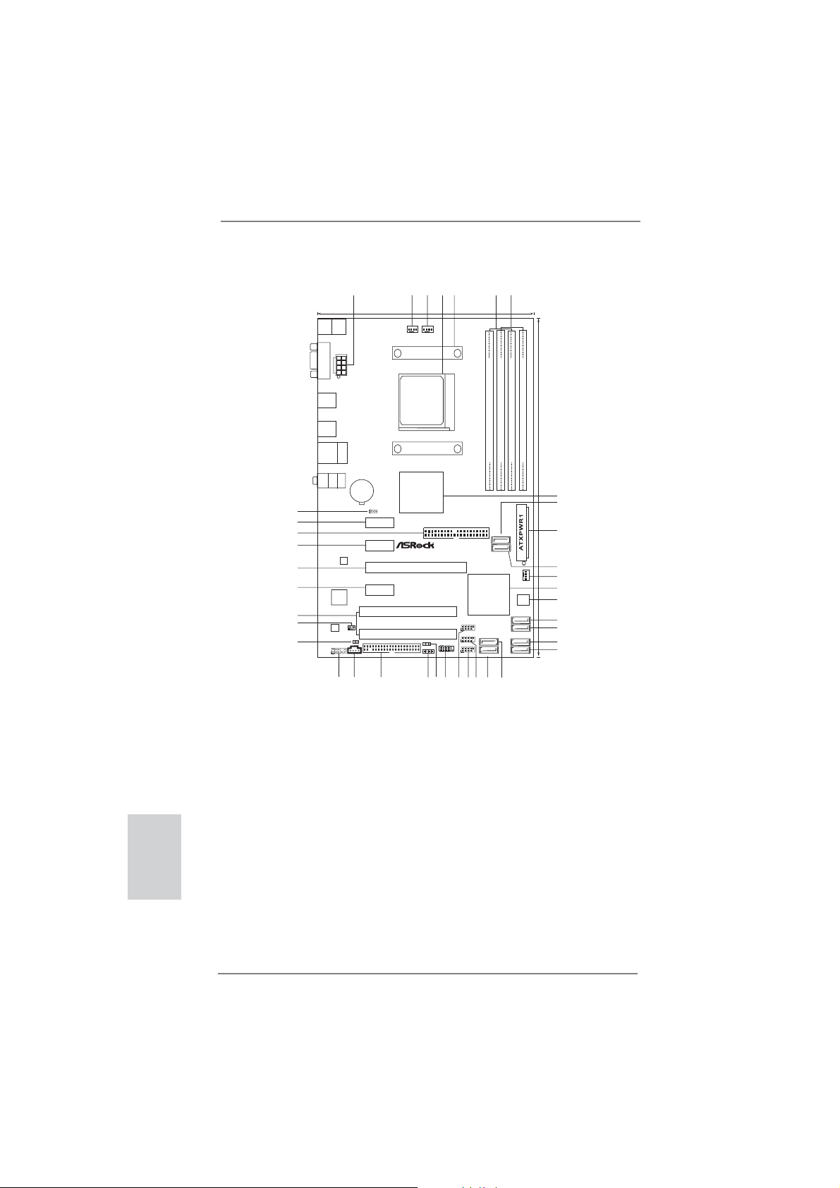
Motherboard Layout
1
19.1cm (7.5-in)
Keyboard
Mouse
ErP/EuP Ready
PS2
PS2
COM1
ATX12V1
USB2.0
T: US B2
B:USB3
USB3.0
T: US B0
B:USB1
USB2.0
Top:
T:USB0
RJ-45
B:USB1
Bottom:
MIC IN
Top:
LINE IN
Center:
FRONT
CMOS
BATTERY
CLRCMOS1
38
37
36
1
35
LAN
34
33
32
31
30
PHY
X
Fast LAN
Super
I/O
Designedin Taipei
AUDIO
1
CODEC
IR1
HDMI_SPDIF1
1
CD1
HD_AUDIO1
1
FLOPPY1
USB 3.0
970DE3/U3S3
PCIE1
PCIE2
PCIE4
2
Chipset
X
Fast RAMXFast USB
PCIE3
RoHS
PCI1
PCI2
AMD
770
5
3
4
AM3+
140W CPU
CPU_FAN1PWR_FAN1
SOCKET AM3b
IDE1
USB8_9
1
USB6_7
1
PANEL1
PLEDPWRBTN
1
USB4_5
PLED1
SPEAKER1
1
1
1
HDLED RESET
DDR3 1866
DDR3_A1(64 bit, 240-pinmodule)
SATA36Gb/s
AMD
SB710
Chipset
SATAII_2(PORT1)
SATAII_1(PORT0)
6
FSB800
DDR3_A2(64 bit, 240-pinmodule)
SATA3_2(PORT7)
SATA3_1(PORT6)
7
FSB800
DDR3_B1(64 bit, 240-pinmodule)
SATAII_6(PORT5)
SATAII_5(PORT4)
SATAII_4(PORT3)
SATAII_3(PORT2)
8Mb
BIOS
DDR3_B2(64 bit, 240-pinmodule)
CHA_FAN1
30.5cm (12.0-in)
Support 8-CoreCPU
8
9
10
11
12
13
14
15
16
17
18
English
29
27
28
25
24
26
23
19
21
20
22
1 ATX 12V Power Connector (ATX12V1) 19 SATA2 Connector (SATA2_2 (PORT 1), Black)
2 Power Fan Connector (PWR_FAN1) 20 SATA2 Connector (SATA2_1 (PORT 1), Black)
3 CPU Fan Connector (CPU_FAN1) 21 USB 2.0 Header (USB6_7, Black)
4 AM3+ CPU Socket 22 USB 2.0 Header (USB4_5, Black)
5 CPU Heatsink Retention Module 23 USB 2.0 Header (USB8_9, Black)
6 2 x 240-pin DDR3 DIMM Slots 24 System Panel Header (PANEL1, Black)
(Dual Channel: DDR3_A1, DDR3_B1; Black) 25 Power LED Header (PLED1)
7 2 x 240-pin DDR3 DIMM Slots 26 Chassis Speaker Header (SPEAKER 1, Black)
(Dual Channel: DDR3_A2, DDR3_B2; Black) 27 Floppy Connector (FLOPPY1)
8 Northbridge Controller 28 Internal Audio Connector: CD1 (Black)
9 SATA3 Connector (SATA3_2 (PORT 7), Gray) 29 Front Panel Audio Header (HD_AUDIO1, Black)
10 ATX Power Connector (ATXPWR1) 30 HDMI_SPDIF Header (HDMI_SPDIF1, Black)
11 SATA3 Connector (SATA3_1 (PORT 6), Gray) 31 Infrared Module Header (IR1)
12 Chassis Fan Connector (CHA_FAN1) 32 PCI Slots (PCI1-2)
13 Southbridge Controller 33 PCI Express 2.0 x1 Slot (PCIE4; Black)
14 SPI Flash Memory (8Mb) 34 PCI Express 2.0 x16 Slot (PCIE3; Black)
15 SATA2 Connector (SATA2_6 (PORT 5), Black) 35 PCI Express 2.0 x1 Slot (PCIE2; Black)
16 SATA2 Connector (SATA2_5 (PORT 4), Black) 36 IDE1 Connector (IDE1, Black)
17 SATA2 Connector (SATA2_4 (PORT 3), Black) 37 PCI Express 2.0 x1 Slot (PCIE1; Black)
18 SATA2 Connector (SATA2_3 (PORT 2), Black) 38 Clear CMOS Jumper (CLRCMOS1)
2
ASRock 970DE3/U3S3 Motherboard
Page 3
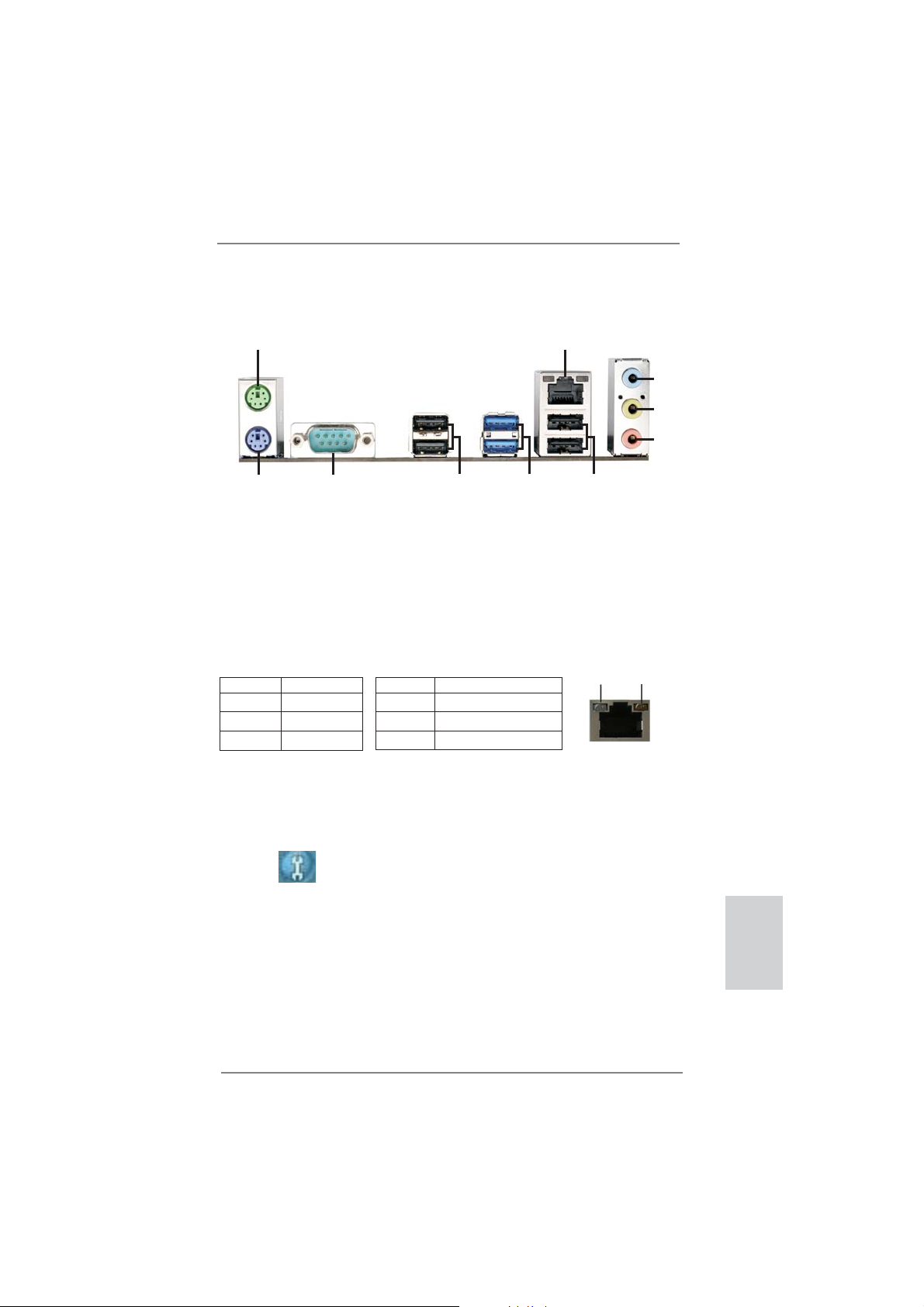
I/O Panel
1
2
3
4
5
910
1 PS/2 Mouse Port (Green) 6 USB 2.0 Ports (USB01)
* 2 LAN RJ-45 Port 7 USB 3.0 Port (USB01)
3 Line In (Light Blue) 8 USB 2.0 Ports (USB23)
** 4 Front Speaker (Lime) 9 Serial Port: COM1
5 Microphone (Pink) 10 PS/2 Keyboard Port (Purple)
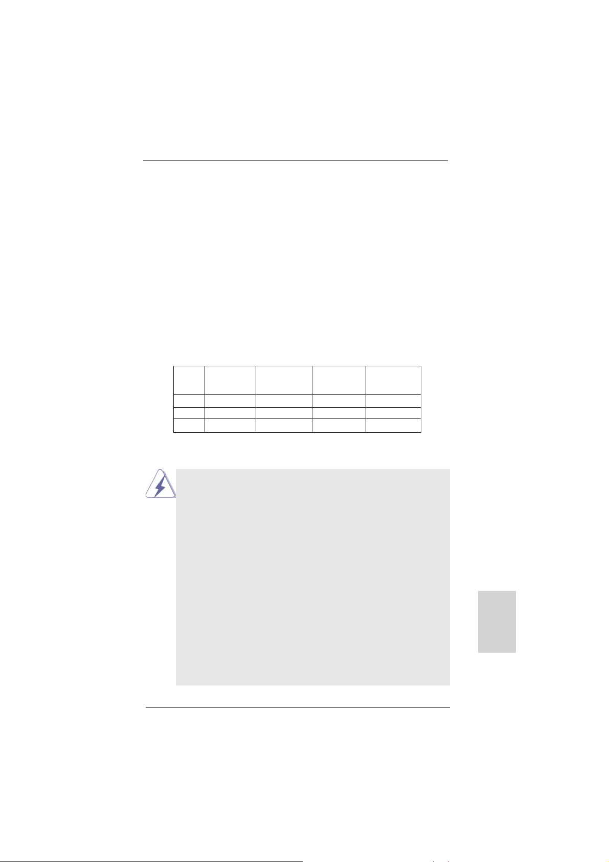
* There are two LED next to the LAN port. Please refer to the table below for the LAN port LED
indications.
Activity/Link LED SPEED LED
Status Description Status Description
LAN Port LED Indications
8
7
6
ACT/LINK
LED
SPEED
LED
Off No Link Off 10Mbps connection
Blinking Data Activity Orange 100Mbps connection
On Link Green 1Gbps connection
LAN Port
** To enable Multi-Streaming function, you need to connect a front panel audio cable to the front
panel audio header. Please refer to below steps for the software setting of Multi-Streaming.
For Windows® XP:
After restarting your computer, you will fi nd “Mixer” tool on your system. Please select “Mixer
ToolBox” , click “Enable playback multi-streaming”, and click “ok”. Choose “2CH” or
“4CH” and then you are allowed to select “Realtek HDA Primary output” to use Rear Speaker
and Front Speaker, or select “Realtek HDA Audio 2nd output” to use front panel audio. Then
reboot your system.
For Windows
After restarting your computer, please double-click “Realtek HD Audio Manager” on the
system tray. Set “Speaker Confi guration” to “Quadraphonic” or “Stereo”. Click “Device
advanced settings”, choose “Make front and rear output devices playbacks two different audio
streams simultaneously”, and click “ok”. Then reboot your system.
®
7 / VistaTM:
ASRock 970DE3/U3S3 Motherboard
English
3
Page 4
1. Introduction
Thank you for purchasing ASRock 970DE3/U3S3 motherboard, a reliable motherboard produced under ASRock’s consistently stringent quality control. It delivers
excellent performance with robust design conforming to ASRock’s commitment to
quality and endurance.
This Quick Installation Guide contains introduction of the motherboard and step-bystep installation guide. More detailed information of the motherboard can be found
in the user manual presented in the Support CD.
Because the motherboard specifi cations and the BIOS software might
be updated, the content of this manual will be subject to change without
notice. In case any modifi cations of this manual occur, the updated ver-
sion will be available on ASRock website without further notice. You may
fi nd the latest VGA cards and CPU support lists on ASRock website as
well. ASRock website http://www.asrock.com
If you require technical support related to this motherboard, please visit
our website for specifi c information about the model you are using.
www.asrock.com/support/index.asp
1.1 Package Contents
ASRock 970DE3/U3S3 Motherboard
(ATX Form Factor: 12.0-in x 7.5-in, 30.5 cm x 19.1 cm)
ASRock 970DE3/U3S3 Quick Installation Guide
ASRock 970DE3/U3S3 Support CD
2 x Serial ATA (SATA) Data Cables (Optional)
1 x I/O Panel Shield
English
ASRock Reminds You...
To get better performance in Windows® 7 / 7 64-bit / VistaTM / VistaTM 64
bit, it is recommended to set the BIOS option in Storage Confi guration
to AHCI mode. For the BIOS setup, please refer to the “User Manual” in
our support CD for details.
4
ASRock 970DE3/U3S3 Motherboard
Page 5
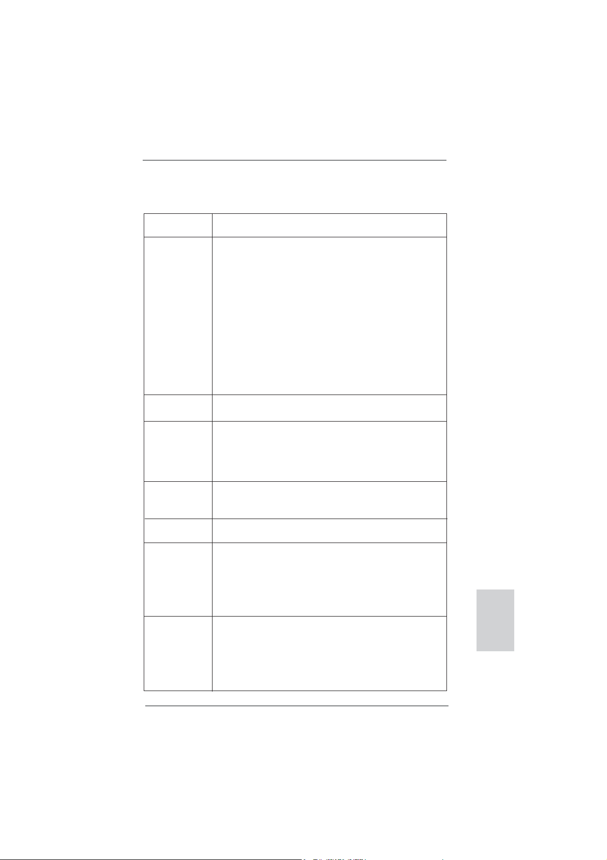
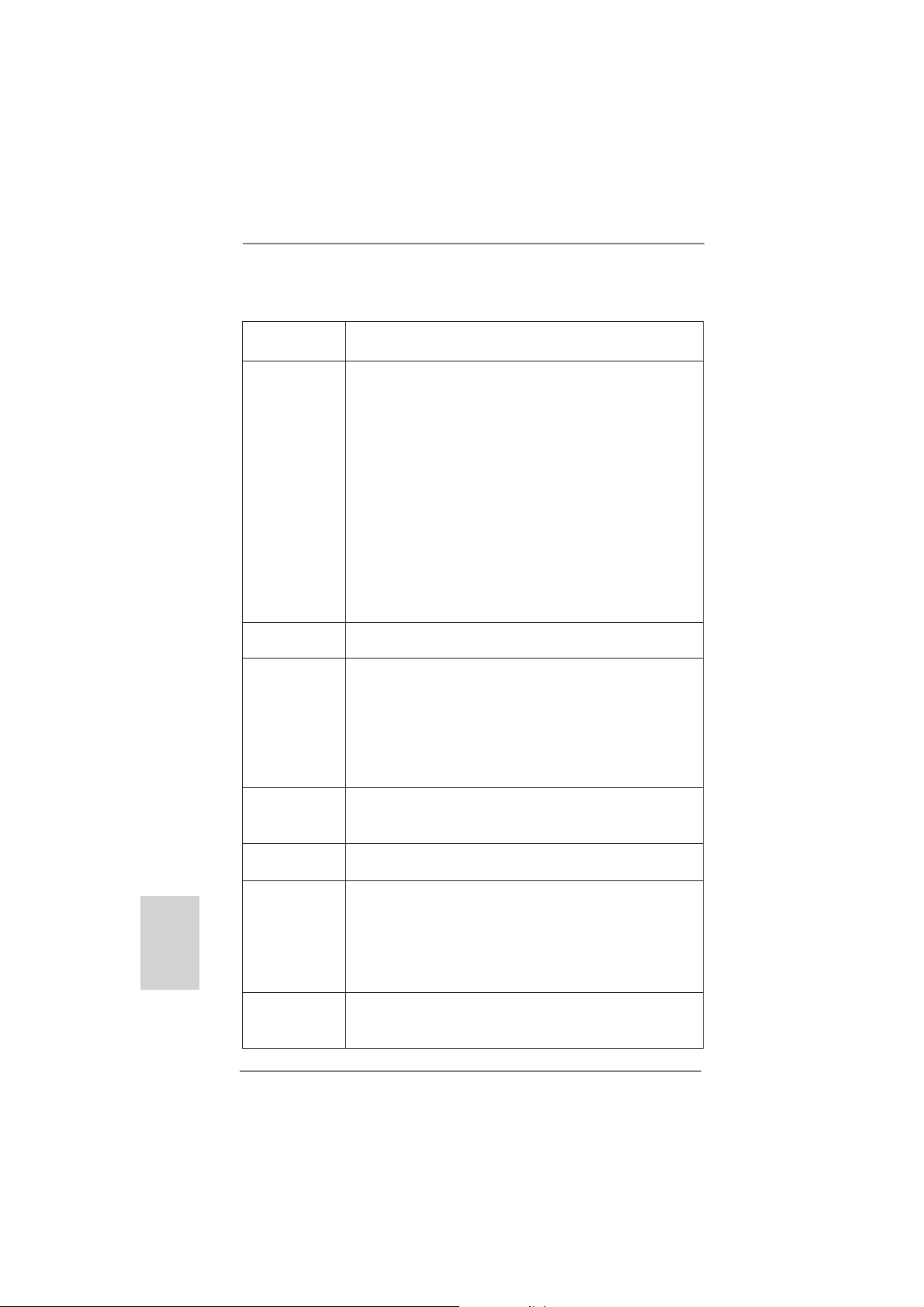
1.2 Specifications
Platform - ATX Form Factor: 12.0-in x 7.5-in, 30.5 cm x 19.1 cm
- All Solid Capacitor design
CPU - Support for Socket AM3+ processors
- Support for Socket AM3 processors: AMD Phenom
X4 / X3 / X2 (except 920 / 940) / Athlon II X4 / X3 / X2 /
Sempron processors
- Supports 8-Core CPU
- Digi Power Design
- Supports CPU up to 140W
- Supports AMD OverDrive
TM
with ACC feature (Advanced
Clock Calibration)
- Supports AMD’s Cool ‘n’ Quiet
TM
Technology
- FSB 2600 MHz (5.2 GT/s)
- Supports Untied Overclocking Technology (see CAUTION 1)
- Supports Hyper-Transport 3.0 (HT 3.0) Technology
Chipset - Northbridge: AMD 770
- Southbridge: AMD SB710
Memory - Dual Channel DDR3 Memory Technology (see CAUTION 2)
- 4 x DDR3 DIMM slots
- Support DDR3 1866(OC)/1600(OC)/1333/1066/800
non-ECC, un-buffered memory (see CAUTION 3)
- Max. capacity of system memory: 32GB (see CAUTION 4)
Expansion Slot - 1 x PCI Express 2.0 x16 slot (PCIE3 @ x16 mode)
- 3 x PCI Express 2.0 x1 slots
- 2 x PCI slots
Audio - 5.1 CH HD Audio (Realtek ALC662 Audio Codec)
- Supports THX TruStudio
TM
LAN - PCIE x1 Gigabit LAN 10/100/1000 Mb/s
- Realtek RTL8111E
- Supports Wake-On-LAN
- Supports LAN Cable Detection
- Supports Energy Effi cient Ethernet 802.3az
- Supports PXE
Rear Panel I/O I/O Panel
- 1 x PS/2 Mouse Port
- 1 x PS/2 Keyboard Port
- 1 x Serial Port: COM1
- 4 x Ready-to-Use USB 2.0 Ports
- 2 x Ready-to-Use USB 3.0 Ports
TM
II X6 /
English
ASRock 970DE3/U3S3 Motherboard
5
Page 6
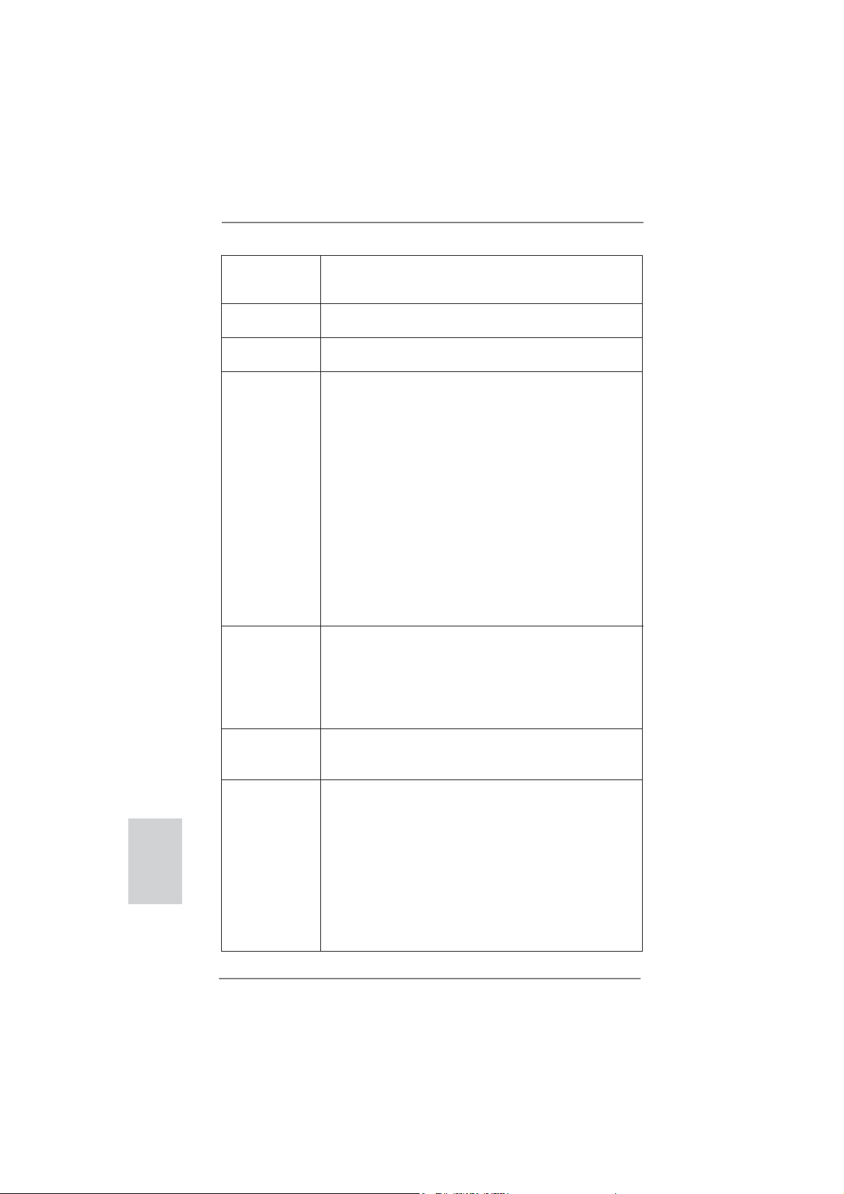
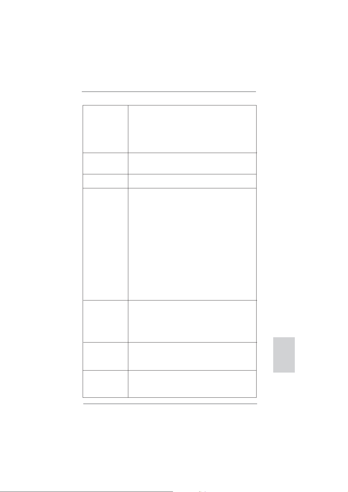
English
- 1 x RJ-45 LAN Port with LED (ACT/LINK LED and SPEED
LED)
- HD Audio Jack: Line in / Front Speaker / Microphone
SATA 3 - 2 x SATA3 6.0 Gb/s connectors by ASMedia ASM1061,
support NCQ, AHCI and “Hot Plug” functions
USB 3.0 - 2 x USB 3.0 ports by ASMedia ASM1042, support
USB 1.0/2.0/3.0 up to 5Gb/s
Connector - 6 x SATA2 3.0 Gb/s connectors, support RAID (RAID 0,
RAID 1, RAID 10 and JBOD), NCQ, AHCI and “Hot Plug”
functions
- 2 x SATA3 6.0Gb/s connectors
- 1 x ATA133 IDE connector (supports 2 x IDE devices)
- 1 x Floppy connector
- 1 x IR header
- 1 x HDMI_SPDIF header
- 1 x Power LED header
- CPU/Chassis/Power FAN connector
- 24 pin ATX power connector
- 8 pin 12V power connector
- CD in header
- Front panel audio connector
- 3 x USB 2.0 headers (support 6 USB 2.0 ports)
BIOS Feature - 8Mb AMI Legal BIOS
- Supports “Plug and Play”
- ACPI 1.1 Compliance Wake Up Events
- Supports jumperfree
- SMBIOS 2.3.1 Support
- CPU, VCCM, NB Voltage Multi-adjustment
Support CD - Drivers, Utilities, AntiVirus Software (Trial Version), AMD
OverDrive
TM
Utility, CyberLink MediaEspresso 6.5 Trial,
ASRock MAGIX Multimedia Suite - OEM
Unique Feature - ASRock OC Tuner (see CAUTION 5)
- ASRock Intelligent Energy Saver (see CAUTION 6)
- ASRock Instant Boot
- ASRock Instant Flash (see CAUTION 7)
- ASRock OC DNA (see CAUTION 8)
- ASRock APP Charger (see CAUTION 9)
- ASRock SmartView (see CAUTION 10)
- ASRock XFast USB (see CAUTION 11)
- ASRock XFast LAN (see CAUTION 12)
- ASRock XFast RAM (see CAUTION 13)
6
ASRock 970DE3/U3S3 Motherboard
Page 7
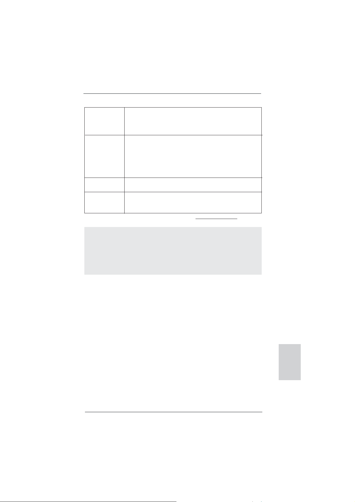
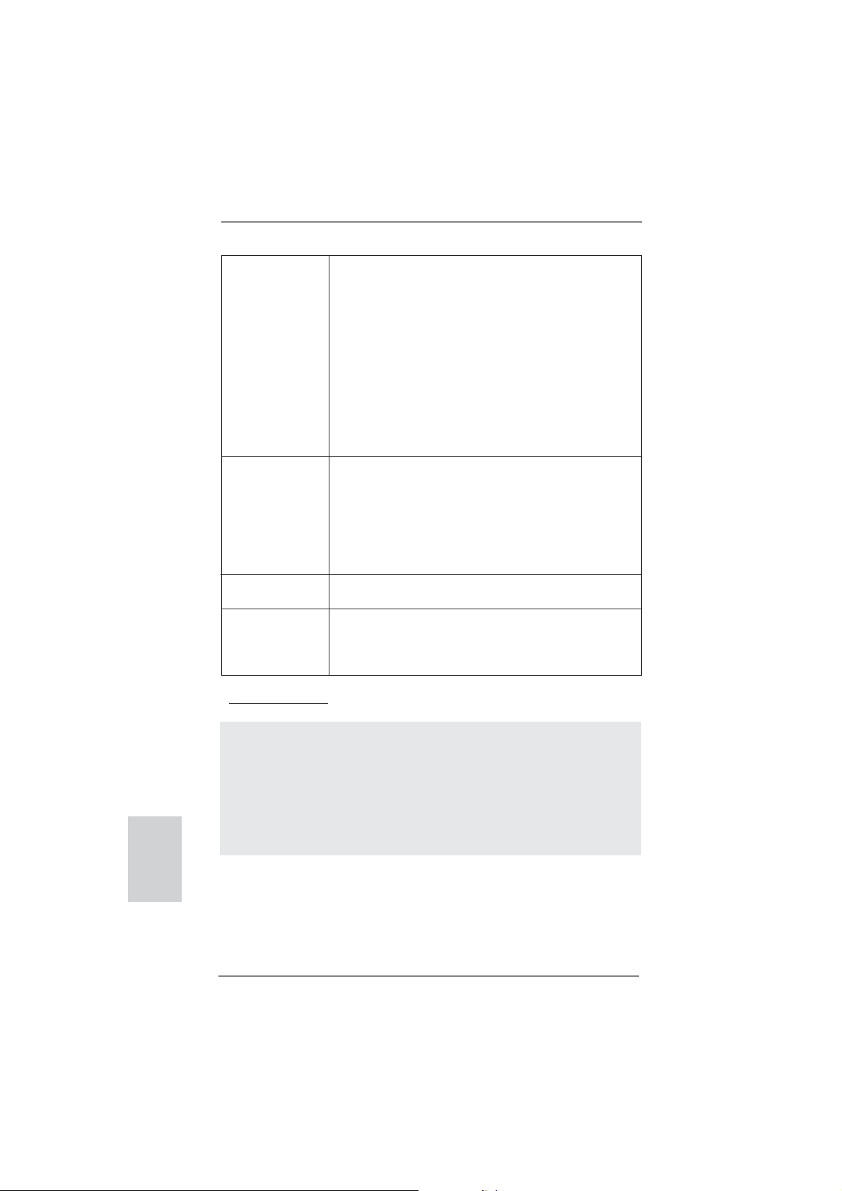
- Hybrid Booster:
- CPU Frequency Stepless Control (see CAUTION 14)
- ASRock U-COP (see CAUTION 15)
- Boot Failure Guard (B.F.G.)
Hardware - CPU Temperature Sensing
Monitor - Chassis Temperature Sensing
- CPU/Chassis/Power Fan Tachometer
- CPU Quiet Fan
- CPU/Chassis/Power Fan Multi-Speed Control
- Voltage Monitoring: +12V, +5V, +3.3V, Vcore
OS - Microsoft
®
Windows® 7 / 7 64-bit / Vista
TM
/ VistaTM 64-bit / XP
/ XP Media Center / XP 64-bit compliant
Certifi cations - FCC, CE, WHQL
- ErP/EuP Ready (ErP/EuP ready power supply is required)
(see CAUTION 16)
* For detailed product information, please visit our website: http://www.asrock.com
WARNING
Please realize that there is a certain risk involved with overclocking, including adjusting the
setting in the BIOS, applying Untied Overclocking Technology, or using the third-party overclocking tools. Overclocking may affect your system stability, or even cause damage to the
components and devices of your system. It should be done at your own risk and expense.
We are not responsible for possible damage caused by overclocking.
ASRock 970DE3/U3S3 Motherboard
English
7
Page 8
English
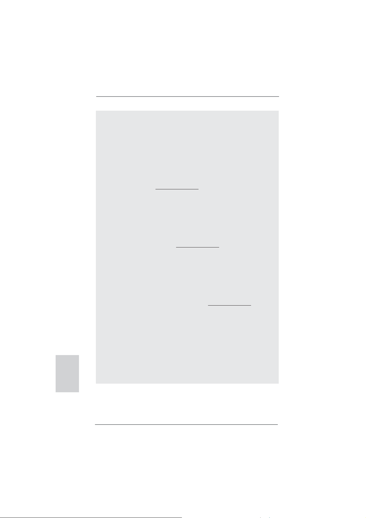
CAUTION!
1. This motherboard supports Untied Overclocking Technology. Please read
“Untied Overclocking Technology” on page 23 for details.
2. This motherboard supports Dual Channel Memory Technology. Before
you implement Dual Channel Memory Technology, make sure to read the
installation guide of memory modules on page 13 for proper installation.
3. Whether 1866/1600MHz memory speed is supported depends on the
AM3/AM3+ CPU you adopt. If you want to adopt DDR3 1866/1600 memory module on this motherboard, please refer to the memory support list
on our website for the compatible memory modules.
ASRock website: http://www.asrock.com
4. Due to the operating system limitation, the actual memory size may be
less than 4GB for the reservation for system usage under Windows
VistaTM / XP. For Windows® 64-bit OS with 64-bit CPU, there is no such
limitation.
5. It is a user-friendly ASRock overclocking tool which allows you to surveil
your system by hardware monitor function and overclock your hardware
devices to get the best system performance under Windows
ment. Please visit our website for the operation procedures of ASRock
OC Tuner. ASRock website: http://www.asrock.com
6. Featuring an advanced proprietary hardware and software design, Intelligent Energy Saver is a revolutionary technology that delivers unparalleled power savings. The voltage regulator can reduce the number of output phases to improve effi ciency when the CPU cores are idle. In other
words, it is able to provide exceptional power saving and improve power
effi ciency without sacrifi cing computing performance. To use Intelligent
Energy Saver function, please enable Cool ‘n’ Quiet option in the BIOS
setup in advance. Please visit our website for the operation procedures
of Intelligent Energy Saver. ASRock website: http://www.asrock.com
7. ASRock Instant Flash is a BIOS fl ash utility embedded in Flash ROM.
This convenient BIOS update tool allows you to update system BIOS
without entering operating systems fi rst like MS-DOS or Windows
this utility, you can press <F6> key during the POST or press <F2> key to
BIOS setup menu to access ASRock Instant Flash. Just launch this tool
and save the new BIOS fi le to your USB fl ash drive, fl oppy disk or hard
drive, then you can update your BIOS only in a few clicks without preparing an additional fl oppy diskette or other complicated fl ash utility. Please
be noted that the USB fl ash drive or hard drive must use FAT32/16/12 fi le
system.
®
environ-
®
. With
®
7 /
8
ASRock 970DE3/U3S3 Motherboard
Page 9
8. The software name itself – OC DNA literally tells you what it is capable of.
OC DNA, an exclusive utility developed by ASRock, provides a conve-
nient way for the user to record the OC settings and share with others. It
helps you to save your overclocking record under the operating system
and simplifi es the complicated recording process of overclocking settings.
With OC DNA, you can save your OC settings as a profi le and share with
your friends! Your friends then can load the OC profi le to their own system
to get the same OC settings as yours! Please be noticed that the OC
profi le can only be shared and worked on the same motherboard.
9. If you desire a faster, less restricted way of charging your Apple devices,
such as iPhone/iPod/iPad Touch, ASRock has prepared a wonderful solu-
tion for you - ASRock APP Charger. Simply installing the APP Charger
driver, it makes your iPhone charged much quickly from your computer
and up to 40% faster than before. ASRock APP Charger allows you to
quickly charge many Apple devices simultaneously and even supports
continuous charging when your PC enters into Standby mode (S1), Sus-
pend to RAM (S3), hibernation mode (S4) or power off (S5). With APP
Charger driver installed, you can easily enjoy the marvelous charging
experience than ever.
ASRock website: http://www.asrock.com/Feature/AppCharger/index.asp
10. ASRock SmartView, a new function of internet browser, is the smart start
page for IE that combines your most visited web sites, your history, your
Facebook friends and your real-time newsfeed into an enhanced view for
a more personal Internet experience. ASRock motherboards are exclu-
sively equipped with the ASRock SmartView utility that helps you keep in
touch with friends on-the-go. To use ASRock SmartView feature, please
make sure your OS version is Windows
bit, and your browser version is IE8.
ASRock website: http://www.asrock.com/Feature/SmartView/index.asp
11. ASRock XFast USB can boost USB storage device performance. The
performance may depend on the property of the device.
12. ASRock XFast LAN provides a faster internet access, which includes be-
low benefi ts. LAN Application Prioritization: You can confi gure your appli-
cation priority ideally and/or add new programs. Lower Latency in Game:
After setting online game priority higher, it can lower the latency in game.
Traffic Shaping: You can watch Youtube HD video and download files
simultaneously. Real-Time Analysis of Your Data: With the status window,
you can easily recognize which data streams you are currently transfer-
ring.
13. ASRock XFast RAM fully utilizes the memory space that cannot be used
under Windows
ing time of previously visited websites, making web surfi ng faster than
ever. And it also boosts the speed of Adobe Photoshop 5 times faster. An-
other advantage of ASRock XFast RAM is that it reduces the frequency of
accessing your SSDs or HDDs in order to extend their lifespan.
®
OS 32-bit CPU. ASRock XFast RAM shortens the load-
®
7 / 7 64 bit / VistaTM / VistaTM 64
English
ASRock 970DE3/U3S3 Motherboard
9
Page 10

14. Although this motherboard offers stepless control, it is not recommended
to perform over-clocking. Frequencies other than the recommended CPU
bus frequencies may cause the instability of the system or damage the
CPU.
15. While CPU overheat is detected, the system will automatically shutdown.
Before you resume the system, please check if the CPU fan on the motherboard functions properly and unplug the power cord, then plug it back
again. To improve heat dissipation, remember to spray thermal grease
between the CPU and the heatsink when you install the PC system.
16. EuP, stands for Energy Using Product, was a provision regulated by European Union to defi ne the power consumption for the completed system.
According to EuP, the total AC power of the completed system shall be
under 1.00W in off mode condition. To meet EuP standard, an EuP ready
motherboard and an EuP ready power supply are required. According to
Intel’s suggestion, the EuP ready power supply must meet the standard
of 5v standby power effi ciency is higher than 50% under 100 mA current
consumption. For EuP ready power supply selection, we recommend you
checking with the power supply manufacturer for more details.
English
10
ASRock 970DE3/U3S3 Motherboard
Page 11
2. Installation
This is an ATX form factor (12.0-in x 7.5-in, 30.5 cm x 19.1 cm) motherboard.
Before you install the motherboard, study the confi guration of your chassis to ensure
that the motherboard fi ts into it.
Pre-installation Precautions
Take note of the following precautions before you install motherboard
components or change any motherboard settings.
Before you install or remove any component, ensure that the
power is switched off or the power cord is detached from the
power supply. Failure to do so may cause severe damage to the
motherboard, peripherals, and/or components.
1. Unplug the power cord from the wall socket before touching any
component.
2. To avoid damaging the motherboard components due to static electricity, NEVER place your motherboard directly on the carpet or the
like. Also remember to use a grounded wrist strap or touch a safety
grounded object before you handle components.
3. Hold components by the edges and do not touch the ICs.
4. Whenever you uninstall any component, place it on a grounded antistatic pad or in the bag that comes with the component.
5. When placing screws into the screw holes to secure the motherboard to the chassis, please do not over-tighten the screws! Doing
so may damage the motherboard.
ASRock 970DE3/U3S3 Motherboard
English
11
Page 12
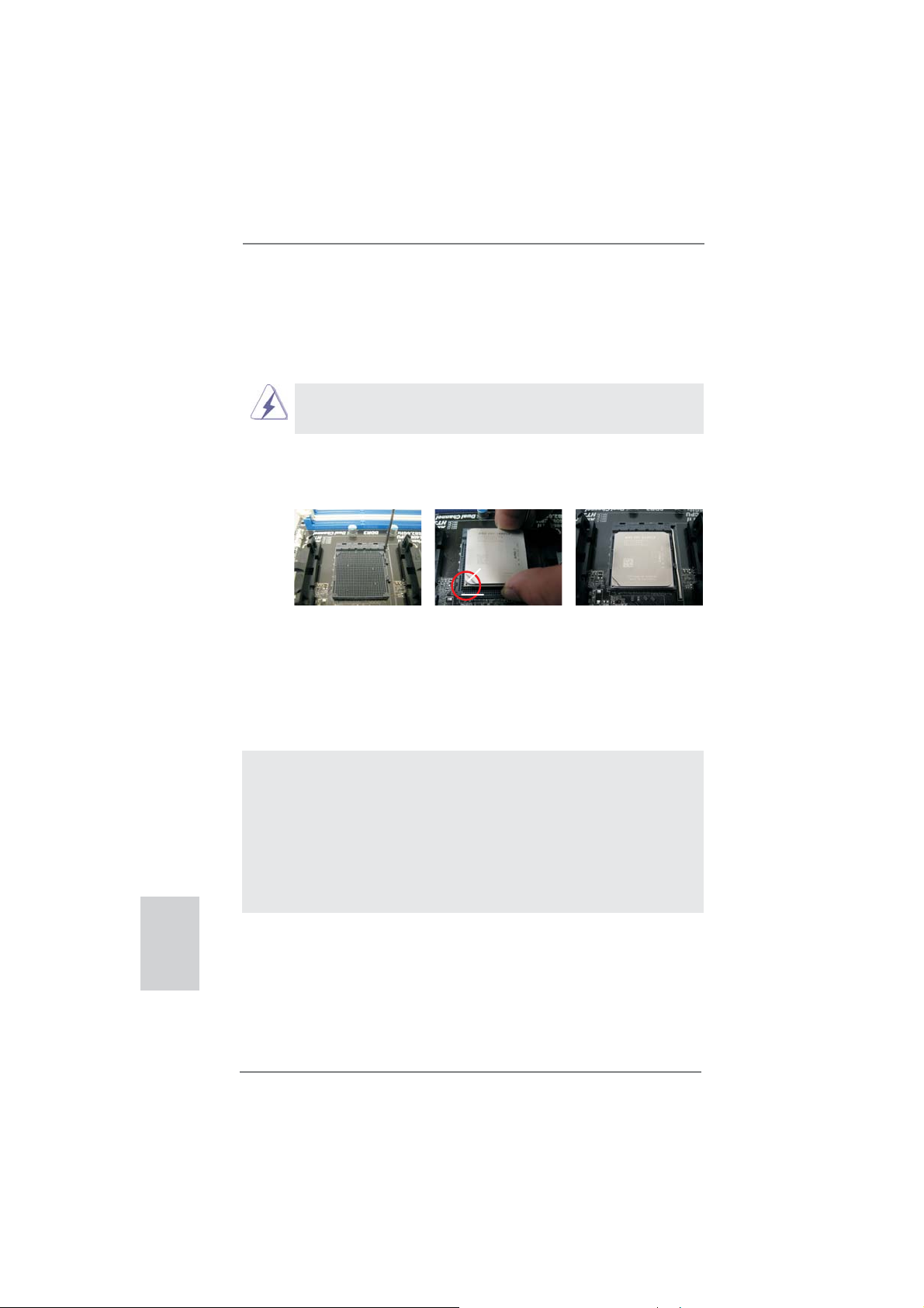
2.1 CPU Installation
Step 1. Unlock the socket by lifting the lever up to a 90
o
angle.
Step 2. Position the CPU directly above the socket such that the CPU corner with
the golden triangle matches the socket corner with a small triangle.
Step 3. Carefully insert the CPU into the socket until it fi ts in place.
The CPU fi ts only in one correct orientation. DO NOT force the CPU
into the socket to avoid bending of the pins.
Step 4. When the CPU is in place, press it fi rmly on the socket while you push
down the socket lever to secure the CPU. The lever clicks on the side tab
to indicate that it is locked.
Lever 90° Up
CPU Golden Triangle
STEP 1:
Lift Up The Socket Lever
STEP 2 / STEP 3:
Match The CPU Golden Triangle
To The Socket Corner Small
Triangle
Socker Corner
Small Triangle
STEP 4:
Push Down And Lock
The Socket Lever
2.2 Installation of CPU Fan and Heatsink
English
After you install the CPU into this motherboard, it is necessary to install a
larger heatsink and cooling fan to dissipate heat. You also need to spray
thermal grease between the CPU and the heatsink to improve heat dissipation. Make sure that the CPU and the heatsink are securely fastened
and in good contact with each other. Then connect the CPU fan to the
CPU FAN connector (CPU_FAN1, see Page 2, No. 3). For proper installation, please kindly refer to the instruction manuals of the CPU fan and
the heatsink.
12
ASRock 970DE3/U3S3 Motherboard
Page 13
2.3 Installation of Memory Modules (DIMM)
This motherboard provides four 240-pin DDR3 (Double Data Rate 3) DIMM slots,
and supports Dual Channel Memory Technology. For dual channel confi guration,
you always need to install identical (the same brand, speed, size and chip-type)
DDR3 DIMM pair in the slots. In other words, you have to install identical DDR3
DIMM pair in Dual Channel (DDR3_A1 and DDR3_B1; Black slots; see p.2 No.6)
or identical DDR3 DIMM pair in Dual Channel (DDR3_A2 and DDR3_B2; Black
slots; see p.2 No.7), so that Dual Channel Memory Technology can be activated.
This motherboard also allows you to install four DDR3 DIMMs for dual channel
confi guration, and please install identical DDR3 DIMMs in all four slots. You may
refer to the Dual Channel Memory Confi guration Table below.
Dual Channel Memory Confi gurations
DDR3_A1 DDR3_A2 DDR3_B1 DDR3_B2
(Black Slot) (Black Slot) (Black Slot) (Black Slot)
(1) Populated - Populated (2) - Populated - Populated
(3)* Populated Populated Populated Populated
For the confi guration (3), please install identical DDR3 DIMMs in all four
*
slots.
1. Please install the memory module into the slots DDR3_A2 and
DDR3_B2 for the fi rst priority.
2. If you want to install two memory modules, for optimal compatibility
and reliability, it is recommended to install them either in the set of
slots DDR3_A1 and DDR3_B1, or in the set of slots DDR3_A2 and
DDR3_B2.
3. If only one memory module or three memory modules are installed
in the DDR3 DIMM slots on this motherboard, it is unable to activate
the Dual Channel Memory Technology.
4. If a pair of memory modules is NOT installed in the same Dual
Channel, for example, installing a pair of memory modules in
DDR3_A1 and DDR3_A2, it is unable to activate the Dual Channel
Memory Technology .
5. It is not allowed to install a DDR or DDR2 memory module into
DDR3 slot; otherwise, this motherboard and DIMM may be damaged.
6. If you adopt DDR3 1866/1600 memory modules on this motherboard, it is recommended to install them on DDR3_A2 and DDR3_
B2 slots.
English
ASRock 970DE3/U3S3 Motherboard
13
Page 14
Installing a DIMM
Please make sure to disconnect power supply before adding or
removing DIMMs or the system components.
Step 1. Unlock a DIMM slot by pressing the retaining clips outward.
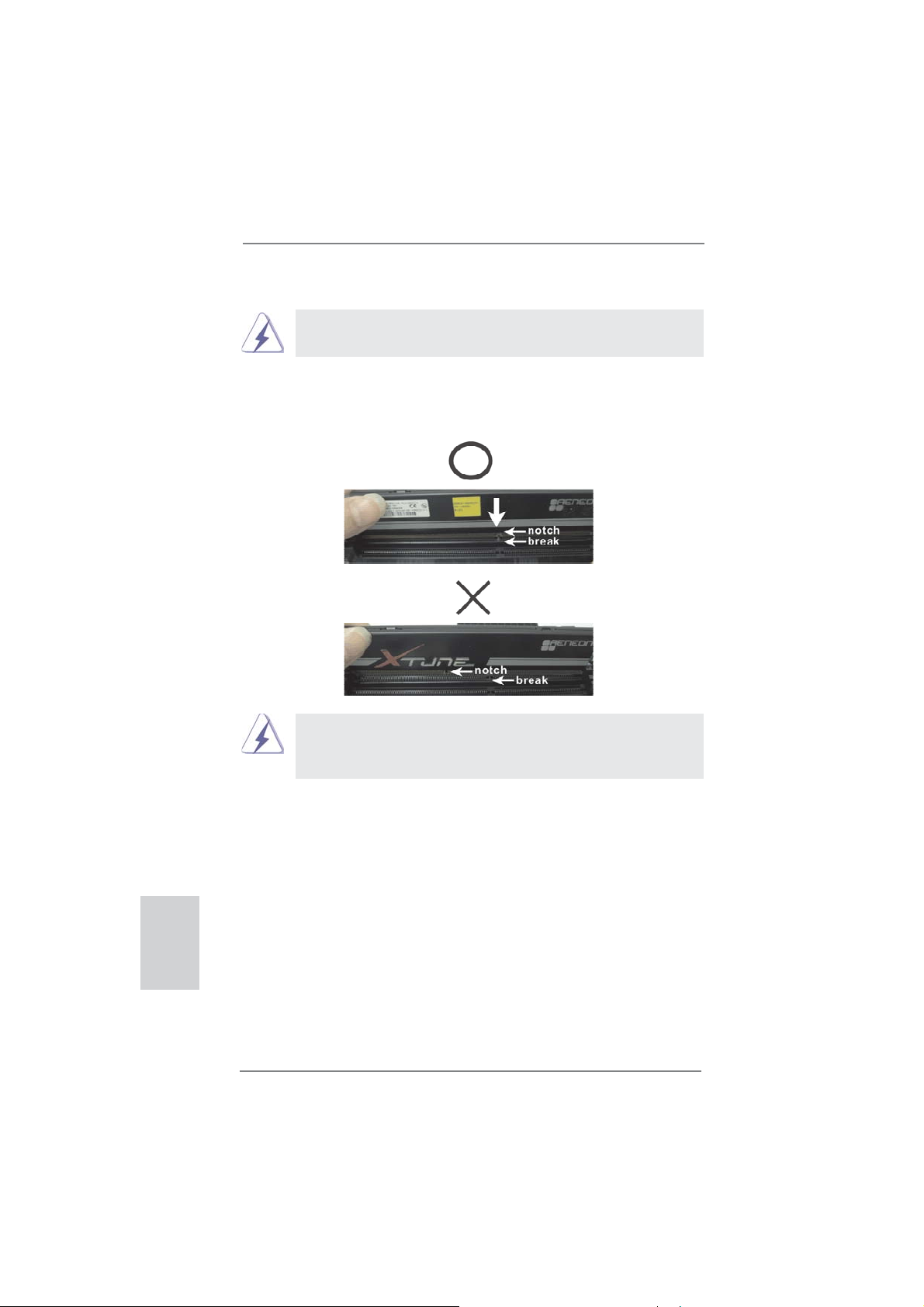
Step 2. Align a DIMM on the slot such that the notch on the DIMM matches the
break on the slot.
The DIMM only fi ts in one correct orientation. It will cause permanent
damage to the motherboard and the DIMM if you force the DIMM into
the slot at incorrect orientation.
English
Step 3. Firmly insert the DIMM into the slot until the retaining clips at both ends
fully snap back in place and the DIMM is properly seated.
14
ASRock 970DE3/U3S3 Motherboard
Page 15

2.4 Expansion Slots (PCI and PCI Express Slots)
There are 2 PCI slots and 4 PCI Express slots on this motherboard.
PCI Slots: PCI slots are used to install expansion cards that have the 32-bit PCI
interface.
PCIE Slots:
PCIE1 / PCIE2 / PCIE4 (PCIE x1 slot; Black) is used for PCI Express
cards with x1 lane width cards, such as Gigabit LAN card and SATA2
card.
PCIE3 (PCIE x16 slot; Black) is used for PCI Express x16 lane width
graphics cards.
Installing an expansion card
Step 1. Before installing the expansion card, please make sure that the power
supply is switched off or the power cord is unplugged. Please read the
documentation of the expansion card and make necessary hardware
settings for the card before you start the installation.
Step 2. Remove the system unit cover (if your motherboard is already installed
in a chassis).
Step 3. Remove the bracket facing the slot that you intend to use. Keep the
screws for later use.
Step 4. Align the card connector with the slot and press fi rmly until the card is
completely seated on the slot.
Step 5. Fasten the card to the chassis with screws.
Step 6. Replace the system cover.
ASRock 970DE3/U3S3 Motherboard
English
15
Page 16
2.5 Jumpers Setup
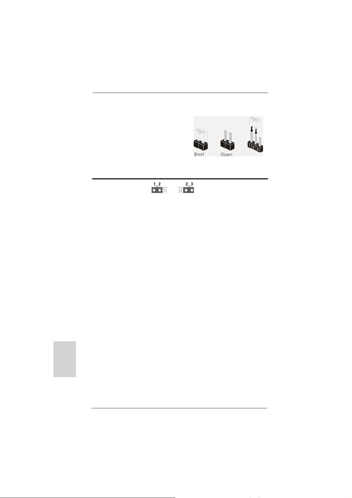
The illustration shows how jumpers are
setup. When the jumper cap is placed on
pins, the jumper is “Short”. If no jumper cap
is placed on pins, the jumper is “Open”. The
illustration shows a 3-pin jumper whose
pin1 and pin2 are “Short” when jumper cap
is placed on these 2 pins.
Jumper Setting Description
Clear CMOS Jumper
(CLRCMOS1)
(see p.2, No. 38)
Note: CLRCMOS1 allows you to clear the data in CMOS. To clear and reset the
system parameters to default setup, please turn off the computer and unplug
the power cord from the power supply. After waiting for 15 seconds, use a
jumper cap to short pin2 and pin3 on CLRCMOS1 for 5 seconds. However,
please do not clear the CMOS right after you update the BIOS. If you need
to clear the CMOS when you just fi nish updating the BIOS, you must boot
up the system fi rst, and then shut it down before you do the clear-CMOS ac-
tion. Please be noted that the password, date, time, user default profi le, 1394
GUID and MAC address will be cleared only if the CMOS battery is removed.
Clear CMOSDefault
English
16
ASRock 970DE3/U3S3 Motherboard
Page 17
2.6 Onboard Headers and Connectors
Onboard headers and connectors are NOT jumpers. Do NOT place
jumper caps over these headers and connectors. Placing jumper caps
over the headers and connectors will cause permanent damage of the
motherboard!
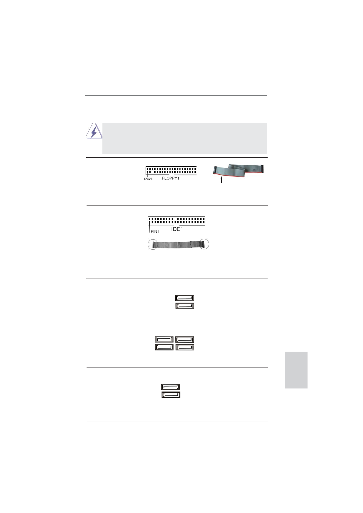
FDD connector
(33-pin FLOPPY1)
(see p.2 No. 27)
the red-striped side to Pin1
Note: Make sure the red-striped side of the cable is plugged into Pin1 side of the
connector.
Primary IDE connector (Black)
(39-pin IDE1, see p.2 No. 36)
connect the blue end
to the motherboard
connect the black end
to the IDE devices
80-conductor ATA 66/100/133 cable
Note: Please refer to the instruction of your IDE device vendor for the details.
Serial ATA2 Connectors These six Serial ATA2 (SATA2)
(SATAII_1 (PORT 0): see p.2, No. 20)
(SATAII_2 (PORT 1): see p.2, No. 19)
(SATAII_3 (PORT 2): see p.2, No. 18)
(SATAII_4 (PORT 3): see p.2, No. 17)
(SATAII_5 (PORT 4): see p.2, No. 16)
(SATAII_6 (PORT 5): see p.2, No. 15)
connectors support SATA data
cables for internal storage
devices. The current SATA2
interface allows up to 3.0 Gb/s
data transfer rate.
SATAII_2 SATAII_4
(PORT 1) (PORT 3)
SATAII_1 SATAII_3
(PORT 0) (PORT 2)
Serial ATA3 Connectors These two Serial ATA3
(SATA3_1 (PORT 6): see p.2, No. 11)
(SATA3_2 (PORT 7): see p.2, No. 9)
(SATA3) connectors support
SATA data cables for internal
SATAII_6
(PORT 5)
SATAII_5
(PORT 4)
SATA3_2
(PORT 7)
storage devices. The current
SATA3 interface allows up to
6.0 Gb/s data transfer rate.
SATA3_1
(PORT 6)
English
ASRock 970DE3/U3S3 Motherboard
17
Page 18
Serial ATA (SATA) Either end of the SATA data
Data Cable cable can be connected to the
(Optional)
SATA / SATA2 / SATA3 hard
disk or the SATA3 connector on
this motherboard.
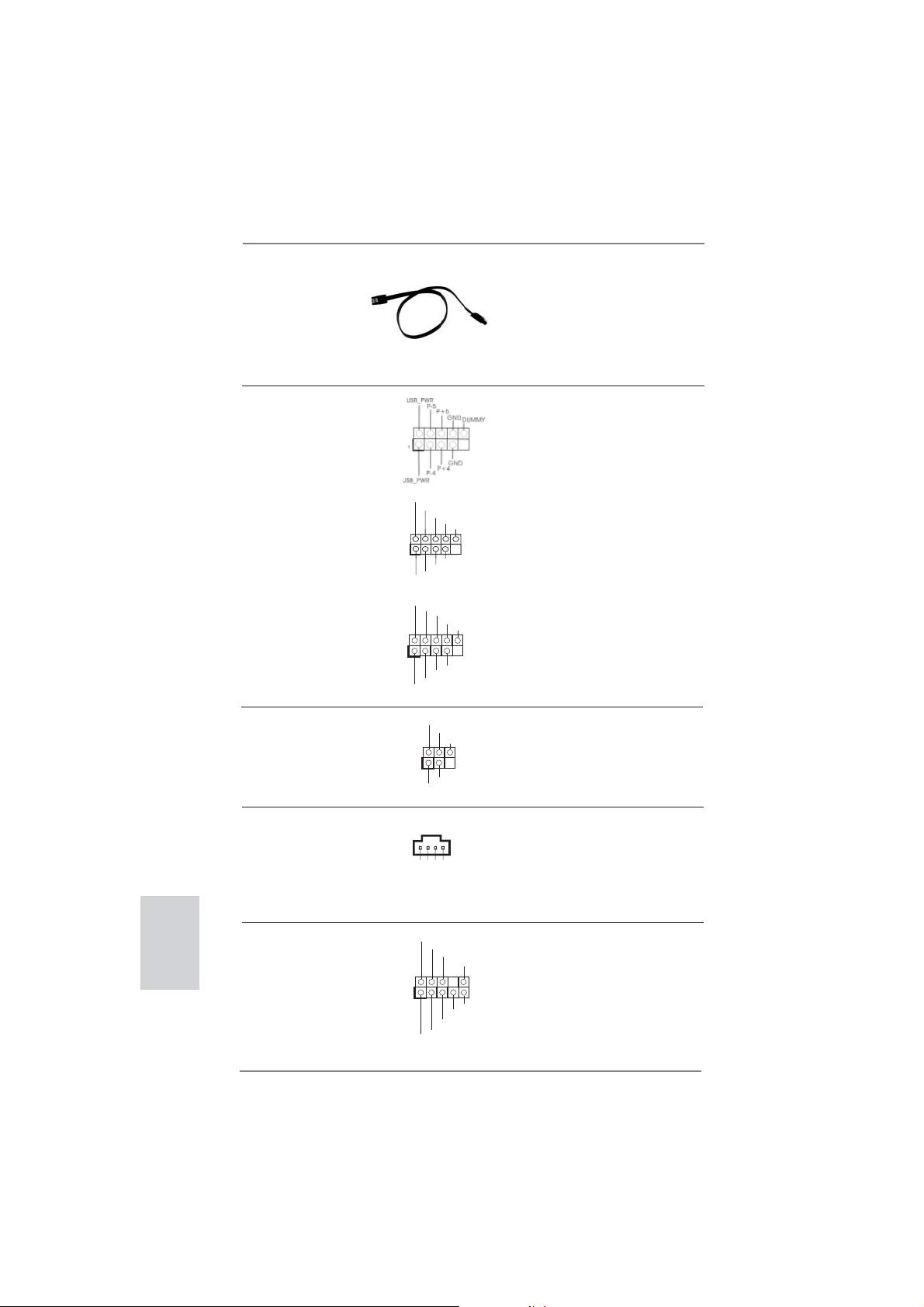
USB 2.0 Headers Besides four default USB 2.0
(9-pin USB4_5)
(see p.2 No. 22)
ports on the I/O panel, there
are three USB 2.0 headers on
this motherboard. Each USB 2.0
header can support two USB
2.0 ports.
(9-pin USB6_7)
(see p.2 No. 21)
(9-pin USB8_9)
(see p.2 No. 23)
1
1
USB_PWR
P-7
P-6
USB_PWR
USB_PWR
P-9
P-8
USB_PWR
P+7
P+6
P+9
P+8
GND
GND
GND
GND
DUMMY
DUMMY
English
Infrared Module Header This header supports an
(5-pin IR1)
optional wireless transmitting
(see p.2 No. 31)
and receiving infrared module.
IRTX
+5VSB
DUMMY
1
GND
IRRX
Internal Audio Connectors This connector allows you to
(4-pin CD1)
(CD1: see p.2 No. 28)
receive stereo audio input from
sound sources such as a
CD1
CD-R
GND
CD-L
GND
CD-ROM, DVD-ROM, TV tuner
card, or MPEG card.
Front Panel Audio Header This is an interface for the front
(9-pin HD_AUDIO1)
(see p.2 No. 29)
panel audio cable that allows
convenient connection and
control of audio devices.
1
GND
PRESENCE#
MIC2_R
MIC2_L
MIC_RET
J_SENSE
OUT2_R
OUT_RET
OUT2_L
18
ASRock 970DE3/U3S3 Motherboard
Page 19
1. High Defi nition Audio supports Jack Sensing, but the panel wire on
the chassis must support HDA to function correctly. Please follow the
instruction in our manual and chassis manual to install your system.
2. If you use AC’97 audio panel, please install it to the front panel audio
header as below:
A. Connect Mic_IN (MIC) to MIC2_L.
B. Connect Audio_R (RIN) to OUT2_R and Audio_L (LIN) to OUT2_L.
C. Connect Ground (GND) to Ground (GND).
D. MIC_RET and OUT_RET are for HD audio panel only. You don’t
need to connect them for AC’97 audio panel.
E. To activate the front mic.
For Windows
Select “Mixer”. Select “Recorder”. Then click “FrontMic”.
For Windows® 7 / 7 64-bit / VistaTM / VistaTM 64-bit OS:
Go to the "FrontMic" Tab in the Realtek Control panel. Adjust
“Recording Volume”.
®
XP / XP 64-bit OS:
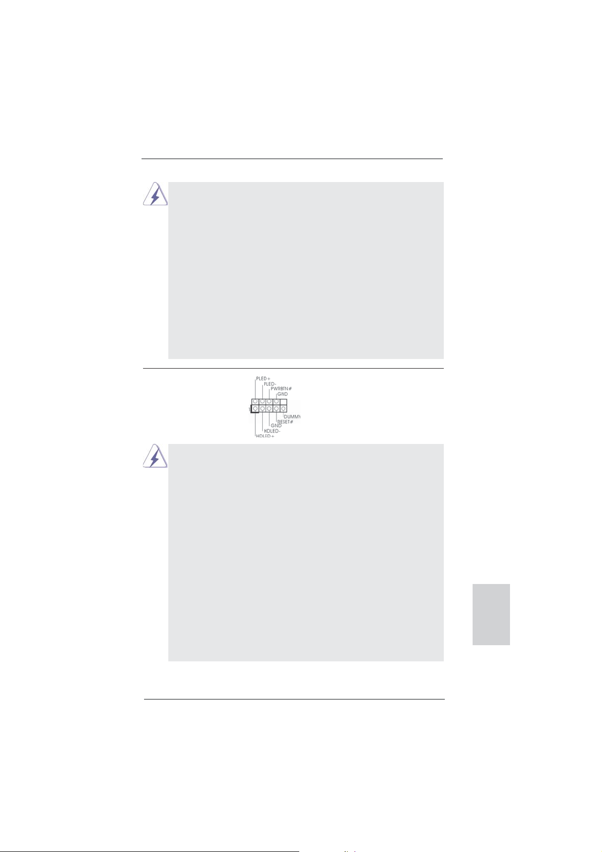
System Panel Header This header accommodates
(9-pin PANEL1)
(see p.2 No. 24)
several system front panel
functions.
Connect the power switch, reset switch and system status indicator
on the chassis to this header according to the pin assignments below.
Note the positive and negative pins before connecting the cables.
PWRBTN (Power Switch):
Connect to the power switch on the chassis front panel. You may confi gure the way to turn off your system using the power switch.
RESET (Reset Switch):
Connect to the reset switch on the chassis front panel. Press the reset
switch to restart the computer if the computer freezes and fails to perform a normal restart.
PLED (System Power LED):
Connect to the power status indicator on the chassis front panel. The
LED is on when the system is operating. The LED keeps blinking
when the sys-tem is in S1 sleep state. The LED is off when the system
is in S3/S4 sleep state or powered off (S5).
HDLED (Hard Drive Activity LED):
Connect to the hard drive activity LED on the chassis front panel. The
LED is on when the hard drive is reading or writing data.
ASRock 970DE3/U3S3 Motherboard
English
19
Page 20
The front panel design may differ by chassis. A front panel module
mainly consists of power switch, reset switch, power LED, hard drive
activity LED, speaker and etc. When connecting your chassis front
panel module to this header, make sure the wire assignments and the
pin assign-ments are matched correctly.
Chassis Speaker Header Please connect the chassis
(4-pin SPEAKER 1)
(see p.2 No. 26)
speaker to this header.
Power LED Header Please connect the chassis
(3-pin PLED1)
(see p.2 No. 25)
power LED to this header to
indicate system power status.
1
+5V
1
PLE D+
DUMMY
DUMMY
PLE D-
PLE D+
SPEAKER
The LED is on when the system
is operating. The LED keeps
blinking in S1 state. The LED is
off in S3/S4 state or S5 state
(power off).
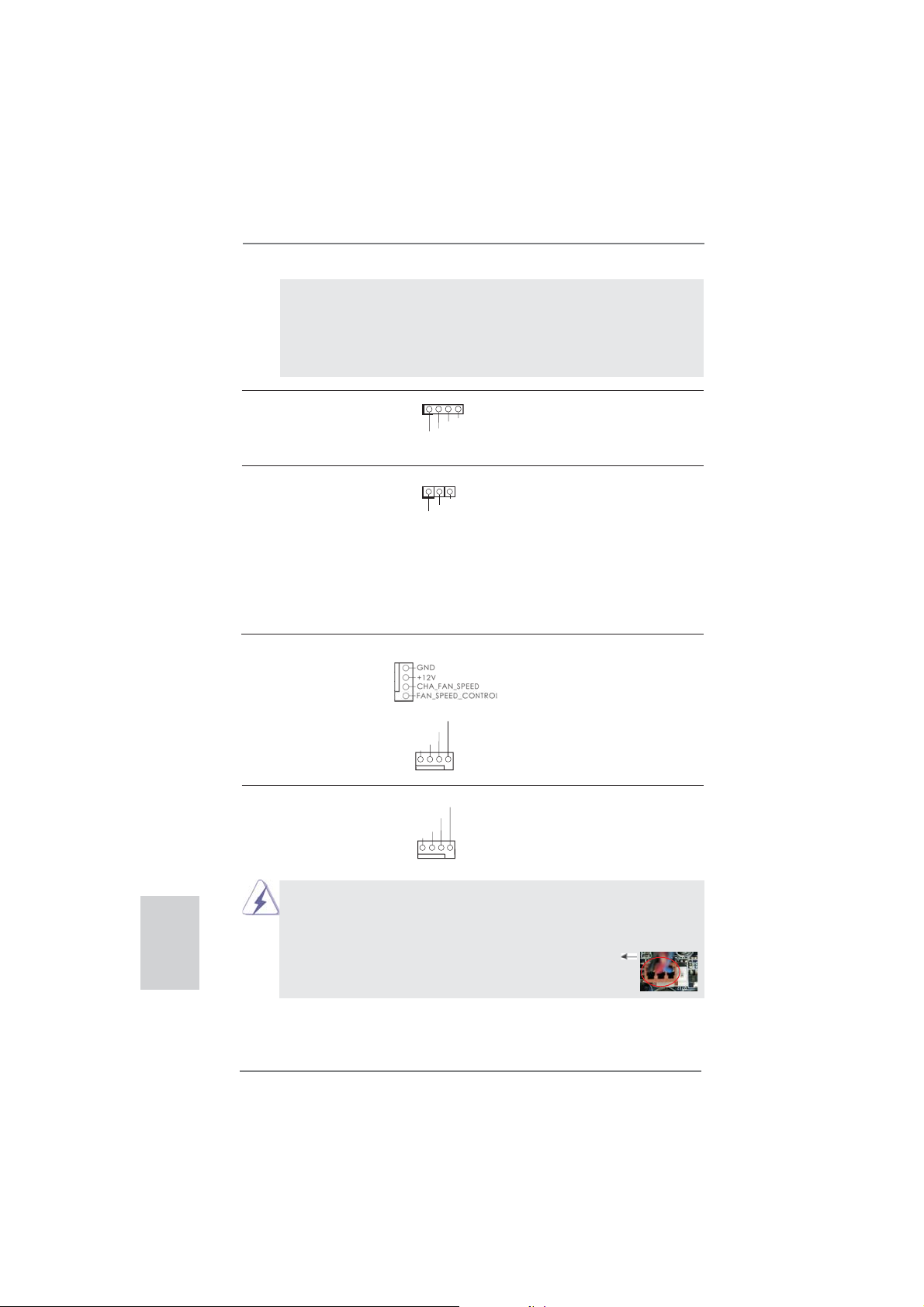
Chassis and Power Fan Connectors Please connect the fan cables
(4-pin CHA_FAN1)
(see p.2 No. 12)
ground pin.
(4-pin PWR_FAN1)
(see p.2 No. 2)
CPU Fan Connectors Please connect the CPU fan
(4-pin CPU_FAN1)
(see p.2 No. 3)
ground pin.
to the fan connectors and
match the black wire to the
FAN_SPEED_CON TROL
PWR_FAN_SPEED
+12V
GND
FAN_SPEED_CONTROL
cable to the connector and
match the black wire to the
CPU_FAN_SPEED
+12V
GND
1 2 3 4
English
Though this motherboard provides 4-Pin CPU fan (Quiet Fan) support, the 3-Pin
CPU fan still can work successfully even without the fan speed control function.
If you plan to connect the 3-Pin CPU fan to the CPU fan connector on this
motherboard, please connect it to Pin 1-3.
Pin 1-3 Connected
3-Pin Fan Installation
20
ASRock 970DE3/U3S3 Motherboard
Page 21
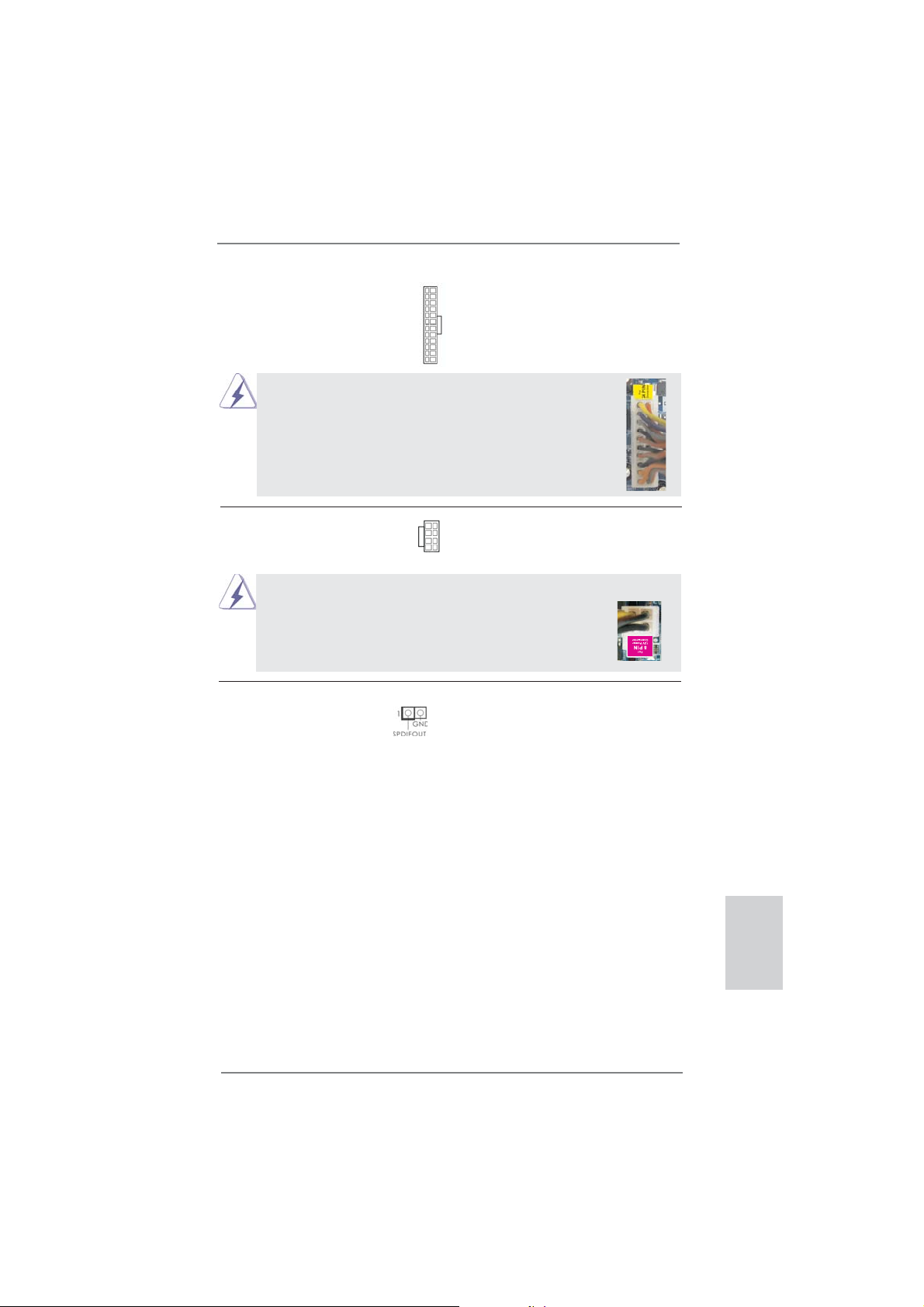
ATX Power Connector Please connect an ATX power
(24-pin ATXPWR1)
(see p.2 No. 10)
Though this motherboard provides 24-pin ATX power connector,
it can still work if you adopt a traditional 20-pin ATX power supply.
supply to this connector.
12
24
1
13
12
To use the 20-pin ATX power supply, please plug your power
supply along with Pin 1 and Pin 13.
24
20-Pin ATX Power Supply Installation
ATX 12V Power Connector Please connect an ATX 12V
(8-pin ATX12V1)
(see p.2 No. 1)
power supply to this connector.
5 1
8 4
1
13
Though this motherboard provides 8-pin ATX 12V power connector, it can still work
if you adopt a traditional 4-pin ATX 12V power supply. To use the
5 1
4-pin ATX power supply, please plug your power supply along with
Pin 1 and Pin 5.
4-Pin ATX 12V Power Supply Installation
8 4
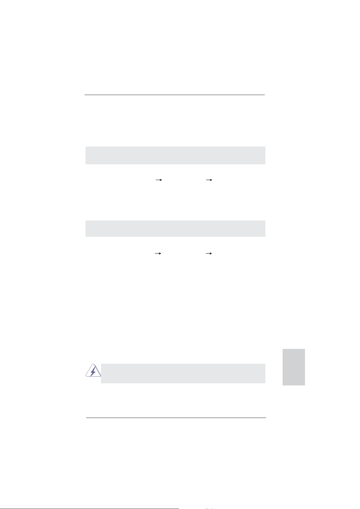
HDMI_SPDIF Header HDMI_SPDIF header, providing
(2-pin HDMI_SPDIF1)
see p.2 No. 30)
(
SPDIF audio output to HDMI
VGA card, allows the system to
connect HDMI Digital TV/
projector/LCD devices. Please
connect the HDMI_SPDIF
connector of HDMI VGA card to
this header.
ASRock 970DE3/U3S3 Motherboard
English
21
Page 22

2.7 Driver Installation Guide
To install the drivers to your system, please insert the support CD to your optical
drive fi rst. Then, the drivers compatible to your system can be auto-detected and
listed on the support CD driver page. Please follow the order from up to bottom side
to install those required drivers. Therefore, the drivers you install can work properly.
2.8 Installing Windows® 7 / 7 64-bit / VistaTM / VistaTM 64-bit / XP /
XP 64-bit With RAID Functions
If you want to install Windows® 7 / 7 64-bit / VistaTM / VistaTM 64-bit / XP / XP 64-bit
on your SATA / SATA2 HDDs with RAID functions, please refer to the document at
the following path in the Support CD for detailed procedures:
..\ RAID Installation Guide
2.9 Installing Windows® 7 / 7 64-bit / VistaTM / VistaTM 64-bit / XP /
XP 64-bit Without RAID Functions
If you want to install Windows® 7 / 7 64-bit / VistaTM / VistaTM 64-bit / XP / XP 64bit OS on your SATA / SATA2 / SATA3 HDDs without RAID functions, please follow
below procedures according to the OS you install.
2.9.1 Installing Windows® XP / XP 64-bit Without RAID Functions
If you want to install Windows® XP / XP 64-bit on your SATA / SATA2 / SATA3 HDDs
without RAID functions, please follow below steps.
English
Using SATA / SATA2 / SATA3 HDDs without NCQ and Hot Plug functions (IDE
mode)
STEP 1: Set up BIOS.
A. Enter BIOS SETUP UTILITY Advanced screen Storage Confi guration.
B. Set the “SATA Operation Mode” option to [IDE] for SATA2 ports.
Set the “Onboard SATA3 Operation Mode” option to [IDE] for SATA3 ports.
STEP 2: Install Windows
®
XP / XP 64-bit OS on your system.
22
ASRock 970DE3/U3S3 Motherboard
Page 23
2.9.2 Installing Windows® 7 / 7 64-bit / VistaTM / VistaTM 64-bit
Without RAID Functions
If you want to install Windows® 7 / 7 64-bit / VistaTM / VistaTM 64-bit on your SATA /
SATA2 / SATA3 HDDs without RAID functions, please follow below steps.
Using SATA / SATA2 / SATA3 HDDs without NCQ and Hot Plug functions (IDE
mode)
STEP 1: Set up BIOS.
A. Enter BIOS SETUP UTILITY Advanced screen Storage Confi guration.
B. Set the “SATA Operation Mode” option to [IDE] for SATA2 ports.
Set the “Onboard SATA3 Operation Mode” option to [IDE] for SATA3 ports.
STEP 2: Install Windows
system.
Using SATA / SATA2 / SATA3 HDDs with NCQ and Hot Plug functions (AHCI
mode)
STEP 1: Set up BIOS.
A. Enter BIOS SETUP UTILITY Advanced screen Storage Confi guration.
B. Set the “SATA Operation Mode” option to [AHCI] for SATA2 ports.
Set the “Onboard SATA3 Operation Mode” option to [AHCI] for SATA3 ports.
STEP 2: Install Windows
system.
®
7 / 7 64-bit / VistaTM / VistaTM 64-bit OS on your
®
7 / 7 64-bit / VistaTM / VistaTM 64-bit OS on your
2.10 Untied Overclocking Technology
This motherboard supports Untied Overclocking Technology, which means during
overclocking, FSB enjoys better margin due to fi xed PCI / PCIE buses. Before you
enable Untied Overclocking function, please enter “Overclock Mode” option of BIOS
setup to set the selection from [Auto] to [Manual]. Therefore, CPU FSB is untied
during overclocking, but PCI / PCIE buses are in the fi xed mode so that FSB can
operate under a more stable overclocking environment.
Please refer to the warning on page 7 for the possible overclocking risk
before you apply Untied Overclocking Technology.
ASRock 970DE3/U3S3 Motherboard
English
23
Page 24

3. BIOS Information
The Flash Memory on the motherboard stores BIOS Setup Utility. When you start up
the computer, please press <F2> or <Del> during the Power-On-Self-Test (POST)
to enter BIOS Setup utility; otherwise, POST continues with its test routines. If you
wish to enter BIOS Setup after POST, please restart the system by pressing <Ctl>
+ <Alt> + <Delete>, or pressing the reset button on the system chassis. The BIOS
Setup program is designed to be user-friendly. It is a menu-driven program, which
allows you to scroll through its various sub-menus and to select among the predetermined choices. For the detailed information about BIOS Setup, please refer to the
User Manual (PDF fi le) contained in the Support CD.
4. Software Support CD information
®
This motherboard supports various Microsoft
64-bit / VistaTM / Vista
that came with the motherboard contains necessary drivers and useful utilities that
will enhance motherboard features. To begin using the Support CD, insert the CD
into your CD-ROM drive. It will display the Main Menu automatically if “AUTORUN”
is enabled in your computer. If the Main Menu does not appear automatically, locate
and double-click on the fi le “ASSETUP.EXE” from the BIN folder in the Support CD
to display the menus.
TM
64-bit / XP / XP Media Center / XP 64-bit. The Support CD
Windows® operating systems: 7 / 7
English
24
ASRock 970DE3/U3S3 Motherboard
Page 25
1. Einführung
Wir danken Ihnen für den Kauf des ASRock 970DE3/U3S3 Motherboard, ein zuverlässiges Produkt, welches unter den ständigen, strengen Qualitätskontrollen von
ASRock gefertigt wurde. Es bietet Ihnen exzellente Leistung und robustes Design,
gemäß der Verpflichtung von ASRock zu Qualität und Halbarkeit. Diese Schnellinstallationsanleitung führt in das Motherboard und die schrittweise Installation
ein. Details über das Motherboard fi nden Sie in der Bedienungsanleitung auf der
Support-CD.
Da sich Motherboard-Spezifi kationen und BIOS-Software verändern
können, kann der Inhalt dieses Handbuches ebenfalls jederzeit geändert
werden. Für den Fall, dass sich Änderungen an diesem Handbuch
ergeben, wird eine neue Version auf der ASRock-Website, ohne weitere
Ankündigung, verfügbar sein. Die neuesten Grafi kkarten und unterstützten
CPUs sind auch auf der ASRock-Website aufgelistet.
ASRock-Website: http://www.asrock.com
Wenn Sie technische Unterstützung zu Ihrem Motherboard oder spezifi sche
Informationen zu Ihrem Modell benötigen, besuchen Sie bitte unsere
Webseite:
www.asrock.com/support/index.asp
1.1 Kartoninhalt
ASRock 970DE3/U3S3 Motherboard
(ATX-Formfaktor: 30.5 cm x 19.1 cm; 12.0 Zoll x 7.5 Zoll)
ASRock 970DE3/U3S3 Schnellinstallationsanleitung
ASRock 970DE3/U3S3 Support-CD
Zwei Serial ATA (SATA) -Datenkabel (optional)
Ein I/O Shield
ASRock erinnert...
Zur besseren Leistung unter Windows® 7 / 7, 64 Bit / Vista
64 Bit empfehlen wir, die Speicherkonfi guration im BIOS auf den AHCI-
Modus einzustellen. Hinweise zu den BIOS-Einstellungen fi nden Sie in
der Bedienungsanleitung auf der mitgelieferten CD.
TM
/ VistaTM
ASRock 970DE3/U3S3 Motherboard
Deutsch
25
Page 26
Deutsch
1.2 Spezifikationen
Plattform - ATX-Formfaktor: 30.5 cm x 19.1 cm; 12.0 Zoll x 7.5 Zoll
- Alle Feste Kondensatordesign
CPU - Unterstützung von Socket AM3+-Prozessoren
- Unterstützung von Socket AM3-Prozessoren: AMD
Phenom
X3 / X2 / Sempron-Prozessor
- Acht-Kern-CPU-bereit
- Digi Power-Design
- Unterstützt CPU bis 140W
- Unterstützt AMD OverDrive
Clock Calibration, Erweiterte Taktkalibrierung)
- Unterstützt Cool ‘n’ Quiet
- FSB 2600 MHz (5.2 GT/s)
- Unterstützt Untied-Übertaktungstechnologie
(siehe VORSICHT 1)
- Unterstützt Hyper-Transport- 3.0 Technologie (HT 3.0)
Chipsatz - Northbridge: AMD 770
- Southbridge: AMD SB710
Speicher - Unterstützung von Dual-Kanal-Speichertechnologie
(siehe VORSICHT 2)
- 4 x Steckplätze für DDR3
- Unterstützt DDR3 1866(OC)/1600(OC)/1333/1066/800
non-ECC, ungepufferter Speicher (siehe VORSICHT 3)
- Max. Kapazität des Systemspeichers: 32GB
(siehe VORSICHT 4)
Erweiterungs- - 1 x PCI-Express-2.0-x16-Steckplätze (PCIE3: x16-Modus)
Steckplätze - 3 x PCI Express 2.0 x1-Steckplätze
- 2 x PCI -Steckplätze
Audio - 5.1
- Unterstützt THX TruStudio
LAN - PCIE x1 Gigabit LAN 10/100/1000 Mb/s
- Realtek RTL8111E
- Unterstützt Wake-On-LAN
- Unterstützt LAN-Kabelerkennung
- Unterstützt energieeffi zientes Ethernet 802.3az
- Unterstützt PXE
E/A-Anschlüsse I/O Panel
an der - 1 x PS/2-Mausanschluss
Rückseite - 1 x PS/2-Tastaturanschluss
TM
II X6 / X4 / X3 / X2 (außer 920 / 940) / Athlon X4 /
TM
mit ACC-Funktion (Advanced
TM
-Technologie von AMD
CH HD Audio (Realtek ALC662 Audio Codec)
TM
26
ASRock 970DE3/U3S3 Motherboard
Page 27
- 1 x Serieller port: COM 1
- 4 x Standard-USB 2.0-Anschlüsse
- 2 x Standard-USB 3.0-Anschlüsse
- 1 x RJ-45 LAN Port mit LED (ACT/LINK LED und SPEED
LED)
- HD Audiobuchse: Audioeingang/ Lautsprecher vorne /
Mikrofon
SATA3 - 2 x SATA 3-Anschlüsse (6,0 Gb/s) durch ASMedia
ASM1061; unterstützt NCQ-, AHCI-und „Hot Plug“ (Hot Plugging)-Funktionen
USB3.0 - 2 x USB 3.0-Ports an der Rückseite durch ASMedia
ASM1042, unterstützt USB 1.0/2.0/3.0 mit bis zu 5 Gb/s
Anschlüsse - 6 x SATA2 3,0 GB/s-Anschlüsse, unterstützen RAID- (RAID
0, RAID 1, RAID 10 und JBOD), NCQ-, AHCI-und Hot Plug
Funktionen
- 2 x SATA3 6,0 GB/s-Anschlüsse
- 1 x ATA133 IDE-Anschlüsse (Unterstützt bis 2 IDE-Geräte)
- 1 x FDD-Anschlüsse
- 1 x Infrarot-Modul-Header
- 1 x HDMI_SPDIF-Anschluss
- 1 x Betriebs-LED-Header
- CPU/Gehäuse/Stromlüfter-Anschluss
- 24-pin ATX-Netz-Header
- 8-pin anschluss für 12V-ATX-Netzteil
- Interne Audio-Anschlüsse
- Anschluss für Audio auf der Gehäusevorderseite
- 3 x USB 2.0-Anschlüsse (Unterstützung 6 zusätzlicher
USB 2.0-Anschlüsse)
BIOS - 8Mb AMIs Legal BIOS
- Unterstützung für “Plug and Play”
- ACPI 1.1-Weckfunktionen
- JumperFree-Modus
- SMBIOS 2.3.1
- CPU, VCCM, NB Stromspannung Multianpassung
Support-CD - Treiber, Dienstprogramme, Antivirussoftware
(Probeversion), AMD OverDrive
TM
-Dienstprogramm,
CyberLink MediaEspresso 6.5-Testversion, ASRock
MAGIX-Multimedia-Suite - OEM
Einzigartige - ASRock OC Tuner (siehe VORSICHT 5)
Eigenschaft - ASRock Intelligent Energy Saver (Intelligente
Energiesparfunktion) (siehe VORSICHT 6)
- ASRock Sofortstart
ASRock 970DE3/U3S3 Motherboard
Deutsch
27
Page 28
- ASRock Instant Flash (siehe VORSICHT 7)
- ASRock OC DNA (siehe VORSICHT 8)
- ASRock APP Charger (siehe VORSICHT 9)
- ASRock SmartView (siehe VORSICHT 10)
- ASRock XFast USB (siehe VORSICHT 11)
- ASRock XFast LAN (siehe VORSICHT 12)
- ASRock XFast RAM (siehe VORSICHT 13)
- Hybrid Booster:
- Schrittloser CPU-Frequenz-Kontrolle
(siehe VORSICHT 14)
- ASRock U-COP (siehe VORSICHT 15)
- Boot Failure Guard (B.F.G. – Systemstartfehlerschutz)
Hardware Monitor - CPU-Temperatursensor
- Motherboardtemperaturerkennung
- Drehzahlmessung für CPU/Gehäuse/Stromlüfter
- CPU lüftergeräuschdämpfung
- Mehrstufi ge Geschwindigkeitsteuerung für CPU/Gehäuse/
Stromlüfter
- Spannungsüberwachung: +12V, +5V, +3.3V, Vcore
®
Betriebssysteme - Unterstützt Microsoft
Vista
TM
64-Bit / XP / XP Media Center / XP 64-Bit
Windows® 7 / 7 64-Bit / VistaTM /
Zertifi zierungen - FCC, CE, WHQL
- Gemäß Ökodesign-Richtlinie (ErP/EuP) (Stromversorgung
gemäß Ökodesign-Richtlinie (ErP/EuP) erforderlich)
(siehe VORSICHT 16)
* Für die ausführliche Produktinformation, besuchen Sie bitte unsere Website:
http://www.asrock.com
Deutsch
28
WARNUNG
Beachten Sie bitte, dass Overclocking, einschließlich der Einstellung im BIOS, Anwenden
der Untied Overclocking-Technologie oder Verwenden von Overclocking-Werkzeugen von
Dritten, mit einem gewissen Risiko behaftet ist. Overclocking kann sich nachteilig auf die
Stabilität Ihres Systems auswirken oder sogar Komponenten und Geräte Ihres Systems
beschädigen. Es geschieht dann auf eigene Gefahr und auf Ihre Kosten. Wir übernehmen
keine Verantwortung für mögliche Schäden, die aufgrund von Overclocking verursacht wurden.
ASRock 970DE3/U3S3 Motherboard
Page 29
VORSICHT!
1. Dieses Motherboard unterstützt die Untied-Übertaktungstechnologie.
Unter “Entkoppelte Übertaktungstechnologie” auf Seite 23 fi nden Sie detail-
lierte Informationen.
2. Dieses Motherboard unterstützt Dual-Kanal-Speichertechnologie. Vor
Implementierung der Dual-Kanal-Speichertechnologie müssen Sie die
Installationsanleitung für die Speichermodule auf Seite 13 zwecks richtiger
Installation gelesen haben.
3. Ob die Speichergeschwindigkeit 1866/1600 MHz unterstützt wird, hängt
von der von Ihnen eingesetzten AM3/AM3+-CPU ab. Schauen Sie bitte
auf unseren Internetseiten in der Liste mit unterstützten Speichermodulen
nach, wenn Sie DDR3 1866/1600-Speichermodule einsetzen möchten.
ASRock-Internetseite: http://www.asrock.com
4. Durch Betriebssystem-Einschränkungen kann die tatsächliche Speichergröße weniger als 4 GB betragen, da unter Windows
etwas Speicher zur Nutzung durch das System reserviert wird. Unter
Windows® OS mit 64-Bit-CPU besteht diese Einschränkung nicht.
5. Es ist ein benutzerfreundlicher ASRock Übertaktenswerkzeug, das
erlaubt, dass Sie Ihr System durch den Hardware-Monitor Funktion zu
überblicken und Ihre Hardware-Geräte übertakten, um die beste
Systemleistung unter der Windows
Sie bitte unsere Website für die Operationsverfahren von ASRock OC
Tuner. ASRock-Internetseite: http://www.asrock.com
6. Mit einer eigenen, modernen Hardware und speziellem Softwaredesign,
bietet der Intelligent Energy Saver eine revolutionäre Technologie zur
bisher unerreichten Energieeinsparung. Ein Spannungsregler kann
die Anzahl von Ausgangsphasen zur Effektivitätsverbessserung
reduzieren, wenn sich die CPU im Leerlauf befi ndet. Mit anderen
Worten: Sie genießen außergewöhnliche Energieeinsparung und
verbesserten Wirkungsgrad ohne Leistungseinschränkungen. Wenn
Sie die Intelligent Energy Saver-Funktion nutzen möchten, aktivieren
Sie zuvor die „Cool ‘n’ Quiet“-Option im BIOS. Weitere
Bedienungshinweise zum Intelligent Energy Saver fi nden Sie auf
unseren Internetseiten. ASRock-Internetseite: http://www.asrock.com
®
Umgebung zu erreichen. Besuchen
®
7 / Vista™ / XP
ASRock 970DE3/U3S3 Motherboard
Deutsch
29
Page 30

Deutsch
7. ASRock Instant Flash ist ein im Flash-ROM eingebettetes BIOS-Flash-
Programm. Mithilfe dieses praktischen BIOS-Aktualisierungswerkzeugs
können Sie das System-BIOS aktualisieren, ohne dafür zuerst Betriebssysteme wie MS-DOS oder Windows
Programm bekommen Sie durch Drücken der <F6>-Taste während des
POST-Vorgangs oder durch Drücken der <F2>-Taste im BIOS-SetupMenü Zugang zu ASRock Instant Flash. Sie brauchen dieses Werkzeug
einfach nur zu starten und die neue BIOS-Datei auf Ihrem USB-FlashLaufwerk, Diskettenlaufwerk oder der Festplatte zu
speichern, und schon können Sie Ihr BIOS mit nur wenigen Klickvorgän-
gen ohne Bereitstellung einer zusätzlichen Diskette oder eines anderen komplizierten Flash-Programms aktualisieren. Achten Sie darauf,
dass das USB-Flash-Laufwerk oder die Festplatte das Dateisystem
FAT32/16/12 benutzen muss.
8. Allein der Name – OC DNA* – beschreibt es wörtlich, was die
Software zu leisten vermag. OC DNA ist ein von ASRock exklusiv
entwickeltes Dienstprogramm, das Nutzern eine bequeme
Möglichkeit bietet, Übertaktungseinstellungen aufzuzeichnen und sie
Anderen mitzuteilen. Es hilft Ihnen, Ihre Übertaktungsaufzeichnung im
Betriebssystem zu speichern und vereinfacht den komplizierten
Aufzeichnungsvorgang von Übertaktungseinstellungen. Mit OC DNA
können Sie Ihre Übertaktungseinstellungen als Profi l abspeichern
und Ihren Freunden zugänglich machen! Ihre Freunde können dann
das Übertaktungsprofi l auf ihren eigenen Systemen laden, um
dieselben Übertaktungseinstellungen. Mit OC DNA können Sie Ihre
Übertaktungseinstellungen als Profi l abspeichern und Ihren
Freunden zugänglich machen! Ihre Freunde können dann das
Übertaktungsprofi l auf ihren eigenen Systemen laden, um dieselben
Übertaktungseinstellungen wie Sie zu erhalten! Beachten Sie bitte,
dass das Übertaktungsprofi l nur bei einem identischen Motherboard
gemeinsam genutzt und funktionsfähig gemacht werden kann.
Übertaktungseinstellungen wie Sie zu erhalten! Beachten Sie bitte,
dass das Übertaktungsprofi l nur bei einem identischen Motherboard
gemeinsam genutzt und funktionsfähig gemacht werden kann.
9. Wenn Sie nach einer schnelleren, weniger eingeschränkten Möglich-
keit zur Aufl adung Ihrer Apple-Geräte (z. B. iPhone/iPad/iPod touch)
suchen, bietet ASRock Ihnen eine wunderbare Lösung – den ASRock
APP Charger. Installieren Sie einfach den ASRock APP Charger-Treiber;
dadurch lädt sich Ihr iPhone wesentlich schneller über einen Computer
auf – genaugenommen bis zu 40 % schneller als zuvor. Der ASRock APP
Charger ermöglicht Ihnen die schnelle Aufl adung mehrerer Apple-Geräte
gleichzeitig; der Ladevorgang wird sogar dann fortgesetzt, wenn der PC
den Ruhezustand (S1), Suspend to RAM-Modus (S3) oder Tiefschlafmodus (S4) aufruft oder ausgeschaltet wird (S5). Nach der
Installation des APP Charger-Treibers können Sie im Handumdrehen das
®
aufrufen zu müssen. Mit diesem
30
ASRock 970DE3/U3S3 Motherboard
Page 31

großartigste Ladeerlebnis überhaupt genießen.
ASRock-Webseite: http://www.asrock.com/Feature/AppCharger/index.
asp
10. SmartView, eine neue Internetbrowserfunktion, ist eine intelligente IEStartseite, die meist besuchte Internetseiten, Ihren Browserverlauf,
Facebook-Freunde und Nachrichten in Echtzeit miteinander kombiniert:
In einer speziellen Ansicht, die das Internet noch angenehmer und aufregender macht. ASRock-Motherboards werden exklusiv mit der SmartView-Software geliefert, die auch dafur sorgt, dass Sie immer mit Ihren
Freunden in Verbindung bleiben. Die SmartView-Funktionen konnen Sie
mit den Windows
und dem Internet Explorer ab Version 8 nutzen.
ASRock-Website: http://www.asrock.com/Feature/SmartView/index.asp
11. ASRocks XFast USB dient der Steigerung der Leistungsfähigkeit Ihrer
USB-Speichergeräte. Die Leistung kann je nach Eigenschaften des
Gerätes variieren.
12. ASRock XFast LAN bietet einen schnelleren Internetzugang mit den
nachfolgenden Vorteilen. LAN-Anwendungspriorisierung: Hiermit konfi gurieren Sie auf ideale Weise Ihre Anwendungspriorität und/oder fügen
neue Programme hinzu. Niedrigere Latenzzeit bei Spielen: Nach Einstellung einer höheren Online-Gamepriorität kann hiermit die Latenzzeit bei
Spielen herabgesetzt werden. Datenverkehrsgestaltung: Sie können
Youtube-Videos in HD anzeigen und gleichzeitig Dateien herunterladen.
Echtzeitanalyse Ihrer Daten: Über das Statusfenster können Sie schnell
ermitteln, welche Datenströme zur Zeit übertragen werden.
13.
Sie ermöglicht die vollständige Nutzung des Speicherplatzes, der unter
Windows®-Betriebssystemen mit 32-Bit-CPU nicht verwendet werden
kann. ASRock XFast RAM verkürzt die Ladezeit zuvor besuchter Webseiten, was das Surfen im Internet mehr denn je beschleunigt. Auch die
Arbeit mit Adobe Photoshop erfolgt fünfmal schneller. Ein weiterer Vorteil
von ASRock XFast RAM liegt in der Reduzierung der Häufi gkeit des Zu-
griffs auf SSDs bzw. HDDs zur Verlän gerung deren Lebenszeit.
14. Obwohl dieses Motherboard stufenlose Steuerung bietet, wird Overclocking nicht empfohlen. Frequenzen, die von den empfohlenen CPUBusfrequenzen abweichen, können Instabilität des Systems verursachen
oder die CPU beschädigen.
15. Wird eine Überhitzung der CPU registriert, führt das System einen automatischen Shutdown durch. Bevor Sie das System neu starten, prüfen Sie bitte,
ob der CPU-Lüfter am Motherboard richtig funktioniert, und stecken Sie bitte
den Stromkabelstecker aus und dann wieder ein. Um die Wärmeableitung
zu verbessern, bitte nicht vergessen, etwas Wärmeleitpaste zwischen CPU
und Kühlkörper zu sprühen.
16. EuP steht für Energy Using Product und kennzeichnet die ÖkodesignRichtlinie, die von der Europäischen Gemeinschaft zur Festlegung des
Energieverbrauchs von vollständigen Systemen in Kraft gesetzt wurde.
Gemäß dieser Ökodesign-Richtlinie (EuP) muss der gesamte Netzstrom
®
-Betriebssystemen 7 / 7, 64 Bit / VistaTM / VistaTM 64 Bit
Deutsch
ASRock 970DE3/U3S3 Motherboard
31
Page 32

verbrauch von vollständigen Systemen unter 1,00 Watt liegen, wenn sie
ausgeschaltet sind. Um dem EuP-Standard zu entsprechen, sind ein EuPfähiges Motherboard und eine EuP-fähige Stromversorgung erforderlich.
Gemäß einer Empfehlung von Intel muss eine EuP-fähige Stromversorgung
dem Standard entsprechen, was bedeutet, dass bei einem Stromverbrauch
von 100 mA die 5-Volt-Standby-Energieeffi zienz höher als 50% sein sollte.
Für die Wahl einer EuP-fähigen Stromversorgung empfehlen wir Ihnen,
weitere Details beim Hersteller der Stromversorgung abzufragen.
Deutsch
32
ASRock 970DE3/U3S3 Motherboard
Page 33

1.3 Einstellung der Jumper
Die Abbildung verdeutlicht, wie Jumper
gesetzt werden. Werden Pins durch
Jumperkappen verdeckt, ist der Jumper
“gebrückt”. Werden keine Pins durch Jumperkappen verdeckt, ist der Jumper “offen”.
Die Abbildung zeigt einen 3-Pin Jumper
dessen Pin1 und Pin2 “gebrückt” sind, bzw.
es befindet sich eine Jumper-Kappe auf
diesen beiden Pins.
Jumper Einstellun
CMOS löschen
(CLRCMOS1, 3-Pin jumper)
(siehe S.2, No. 38)
DefaultEinstellung
Hinweis: CLRCMOS1 erlaubt Ihnen das Löschen der CMOS-Daten. Diese beinhal-
ten das System-Passwort, Datum, Zeit und die verschiedenen BIOS-Parameter. Um die Systemparameter zu löschen und auf die Werkseinstellung
zurückzusetzen, schalten Sie bitte den Computer ab und entfernen das
Stromkabel. Benutzen Sie eine Jumperkappe, um die
Pin 2 und Pin 3 an CLRCMOS1 für 5 Sekunden kurzzuschließen. Bitte
vergessen Sie nicht, den Jumper wieder zu entfernen, nachdem das
CMOS gelöscht wurde. Bitte vergessen Sie nicht, den Jumper wieder zu
entfernen, nachdem das CMOS gelöscht wurde. Wenn Sie den CMOSInhalt gleich nach dem Aktualisieren des BIOS löschen müssen, müssen
Sie zuerst das System starten und dann wieder ausschalten, bevor Sie
den CMOS-Inhalt löschen.
CMOS
löschen
ASRock 970DE3/U3S3 Motherboard
Deutsch
33
Page 34

1.4 Integrierte Header und Anschlüsse
Anschluss für das
Floppy-Laufwerk
(33-Pin FLOPPY1)
(siehe S.2 - No. 27)
Hinweis: Achten Sie darauf, dass die rotgestreifte Seite des Kabel mit der Stift 1-
Seite des Anschlusses verbunden wird.
Primärer IDE-Anschluss (schwarz)
(39-pin IDE1, siehe S.2 - No. 36)
Blauer Anschluss Schwarzer Anschluss
zum Motherboard zur Festplatte
80-adriges ATA 66/100/133 Kabel
Hinweis: Details entnehmen Sie bitte den Anweisungen Ihres IDE-Gerätehändlers.
Integrierte Header und Anschlüsse sind KEINE Jumper. Setzen Sie KEINE Jumperkappen auf diese Header und Anschlüsse. Wenn Sie Jumperkappen auf Header und Anschlüsse setzen, wird das Motherboard
unreparierbar beschädigt!
die rotgestreifte Seite auf Stift 1
Deutsch
34
Seriell-ATAII-Anschlüsse Diese sechs Serial ATAII-
(SATAII_1 (PORT 0): siehe S.2 - No. 20)
(SATAII_2 (PORT 1): siehe S.2 - No. 19)
(SATAII_3 (PORT 2): siehe S.2 - No. 18)
(SATAII_4 (PORT 3): siehe S.2 - No. 17)
(SATAII_5 (PORT 4): siehe S.2 - No. 16)
(SATAII_6 (PORT 5): siehe S.2 - No. 15)
Datenübertragungsrate bis
(SATAII-)Verbínder
unterstützten SATA-Datenkabel
für interne
Massenspeichergeräte. Die
aktuelle SATAII-Schnittstelle
ermöglicht eine
SATAII_2 SATAII_4
(PORT 1) (PORT 3)
SATAII_6
(PORT 5)
SATAII_5
(PORT 4)
3,0 Gb/s.
SATAII_1 SATAII_3
(PORT 0) (PORT 2)
ASRock 970DE3/U3S3 Motherboard
Page 35

Seriell-ATA3-Anschlüsse Diese zwei Serial ATA3-
(SATA3_1 (PORT 6): siehe S.2 - No. 11)
(SATA3_2 (PORT 7): siehe S.2 - No. 9)
SATA3_2
(SATA3-)Verbínder
(PORT 7)
unterstützten SATA-Datenkabel
für interne
Massenspeichergeräte. Die
aktuelle SATA3- Schnittstelle
SATA3_1
(PORT 6)
ermöglicht eine
Datenübertragungsrate bis
6,0 Gb/s.
Serial ATA- (SATA-) SJedes Ende des SATA
Datenkabel Datenkabels kann an die
(Option)
SATA / SATAII / SATA3
Festplatte oder das SATA3
Verbindungsstück auf dieser
Hauptplatine angeschlossen
werden.
USB 2.0-Header Zusätzlich zu den vier
(9-pol. USB4_5)
(siehe S.2 - No. 22)
üblichen USB 2.0-Ports an den
I/O-Anschlüssen befi nden sich
drei USB 2.0-
Anschlussleisten am
Motherboard. Pro USB 2.0-
(9-pol. USB6_7)
(siehe S.2 - No. 21)
(9-pol. USB8_9)
(siehe S.2 - No. 23)
Anschlussleiste werden zwei
USB 2.0-Ports unterstützt.
1
1
USB_PWR
P-7
P-6
USB_PWR
USB_PWR
P-9
P-8
USB_PWR
P+7
P+6
P+9
P+8
GND
GND
GND
GND
DUMMY
DUMMY
Infrarot-Modul-Header Dieser Header unterstützt ein
(5-pin IR1)
optionales, drahtloses Sende-
(siehe S.2 - No. 31)
und Empfangs-Infrarotmodul.
IRTX
+5VSB
DUMMY
1
GND
IRRX
ASRock 970DE3/U3S3 Motherboard
Deutsch
35
Page 36

Interne Audio-Anschlüsse Diese ermöglichen Ihnen
(4-Pin CD1)
(siehe S.2 - No. 28)
Stereo-Signalquellen, wie z. B.
CD-ROM, DVD-ROM, TV-Tuner
CD1
CD-L
GND
GND
CD-R
oder MPEG-Karten mit Ihrem
System zu verbinden.
Anschluss für Audio auf Dieses Interface zu einem
der Gehäusevorderseite Audio-Panel auf der Vorder
(9-Pin HD_AUDIO1)
(siehe S.2 - No. 29)
seite Ihres Gehäuses,
ermöglicht Ihnen eine bequeme
Anschlussmöglichkeit und
Kontrolle über Audio-Geräte.
1
GND
PRESENCE#
MIC2_R
MIC2_L
MIC_RET
J_SENSE
OUT2_R
OUT_RET
OUT2_L
1. High Defi nition Audio unterstützt Jack Sensing (automatische Erkennung
falsch angeschlossener Geräte), wobei jedoch die Bildschirmverdrahtung
am Gehäuse HDA unterstützen muss, um richtig zu funktionieren.
Beachten Sie bei der Installation im System die Anweisungen in unserem
Handbuch und im Gehäusehandbuch.
2. Wenn Sie die AC’97-Audioleiste verwenden, installieren Sie diese wie
nachstehend beschrieben an der Front-Audioanschlussleiste:
A. Schließen Sie Mic_IN (MIC) an MIC2_L an.
B. Schließen Sie Audio_R (RIN) an OUT2_R und Audio_L (LIN) an OUT2_L an.
C. Schließen Sie Ground (GND) an Ground (GND) an.
D. MIC_RET und OUT_RET sind nur für den HD-Audioanschluss gedacht. Diese
Anschlüsse müssen nicht an die AC’97-Audioleiste angeschlossen werden.
E. So aktivieren Sie das Mikrofon an der Vorderseite.
Bei den Betriebssystemen Windows
®
XP / XP 64 Bit:
Wählen Sie „Mixer“. Wählen Sie „Recorder“ (Rekorder). Klicken Sie dann
auf „FrontMic“ (Vorderes Mikrofon).
Bei den Betriebssystemen Windows
®
7 / 7 64 Bit / VistaTM / VistaTM 64 Bit:
Wählen Sie im Realtek-Bedienfeld die „FrontMic“ (Vorderes Mikrofon)-
Registerkarte. Passen Sie die „Recording Volume“ (Aufnahmelautstärke)
an.
Deutsch
36
System Panel-Header Dieser Header unterstützt
(9-pin PANEL1)
(siehe S.2 - No. 24)
mehrere Funktion der
Systemvorderseite.
ASRock 970DE3/U3S3 Motherboard
Page 37

Schließen Sie die Ein-/Austaste, die Reset-Taste und die
Systemstatusanzeige am Gehäuse an diesen Header an; befolgen Sie
dabei die nachstehenden Hinweise zur Pinbelegung. Beachten Sie die
positiven und negativen Pins, bevor Sie die Kabel anschließen.
PWRBTN (Ein-/Ausschalter):
Zum Anschließen des Ein-/Ausschalters an der Frontblende des Gehäu
ses. Sie können konfi gurieren, wie das System mit Hilfe des
Ein-/Ausschalters ausgeschaltet werden können soll.
RESET (Reset-Taste):
Zum Anschließen der Reset-Taste an der Frontblende des Gehäuses.
Mit der Reset-Taste können Sie den Computer im Falle eines Absturzes
neu starten.
PLED (Systembetriebs-LED):
Zum Anschließen der Betriebsstatusanzeige an der Frontblende des
Gehäuses. Die LED leuchtet, wenn das System in Betrieb ist. Die LED
blinkt, wenn sich das System im Ruhezustand S1 befi ndet. Die LED
schaltet sich aus, wenn sich das System in den Modi S3/S4 befi ndet
oder ausgeschaltet ist (S5).
HDLED (Festplattenaktivitäts-LED):
Zum Anschließen der Festplattenaktivitäts-LED an der Frontblende des
Gehäuses. Die LED leuchtet, wenn die Festplatte Daten liest oder
schreibt.
Das Design der Frontblende kann je nach Gehäuse variiere. Ein
Frontblendenmodul besteht hauptsächlich aus einer Ein-/Austaste, einer
Reset-Taste, einer Betriebs-LED, einer Festplattenaktivitäts-LED,
Lautsprechern, etc. Stellen Sie beim Anschließen des
Frontblendenmoduls Ihres Gehäuses an diesem Header sicher, dass die
Kabel- und Pinbelegung korrekt übereinstimmen.
Gehäuselautsprecher-Header Schließen Sie den
(4-pin SPEAKER1)
(siehe S.2 - No. 26)
Betriebs-LED-Header Bitte schließen Sie die
(3-pin PLED1)
(siehe S.2 - No. 25)
Gehäuselautsprecher an
diesen Header an.
Betriebs-LED des Gehäuses
zur Anzeige des
1
PLE D+
PLE D+
PLE D-
Systembetriebsstatus an
diesem Header an. Die LED
leuchtet, wenn das System in
Deutsch
Betrieb ist. Die LED blinkt im
S1-Zustand. Im S3-/S4- oder
S5-Zustand (ausgeschaltet)
leuchtet die LED nicht.
37
ASRock 970DE3/U3S3 Motherboard
Page 38

Gehäuse- und Stromlüfteranschlüsse Verbinden Sie die Lüfterkabel
(4-pin CHA_FAN1)
(siehe S.2, No. 12)
den Schutzleiterstift
(4-pin PWR_FAN1)
(siehe S.2 - No. 2)
mit den Lüfteranschlüssen,
wobei der schwarze Draht an
FAN_SPEED_CON TROL
PWR_FAN_SPEED
+12V
GND
angeschlossenwird.
Deutsch
CPU-Lüfteranschluss Verbinden Sie das CPU -
(4-pin CPU_FAN1)
(siehe S.2 - No. 3)
Lüfterkabel mit diesem
Anschluss und passen Sie den
schwarzen Draht dem
Erdungsstift an.
FAN_SPEED_CONTROL
CPU_FAN_SPEED
+12V
GND
1 2 3 4
Obwohl dieses Motherboard einen vierpoligen CPU-Lüfteranschluss
(Quiet Fan) bietet, können auch CPU-Lüfter mit dreipoligem Anschluss
angeschlossen werden; auch ohne Geschwindigkeitsregulierung. Wenn
Sie einen dreipoligen CPU-Lüfter an den CPU-Lüferanschluss dieses
Motherboards anschließen möchten, verbinden Sie ihn bitte mit den
Pins 1 – 3.
Pins 1–3 anschließen
Lüfter mit dreipoligem Anschluss installieren
ATX-Netz-Header Verbinden Sie die ATX-
(24-pin ATXPWR1)
(siehe S.2 - No. 10)
Obwohl dieses Motherboard einen 24-pol. ATX-
Stromversorgung mit diesem
Header.
12 124
13
12
24
Stromanschluss bietet, kann es auch mit einem
modifi zierten traditionellen 20-pol. ATX-Netzteil
verwendet werden. Um ein 20-pol. ATX-Netzteil zu
verwenden, stecken Sie den Stecker mit Pin 1 und
Pin 13 ein.
Installation eines 20-pol. ATX-Netzteils
1
13
ATX 12V Anschluss Bitte schließen Sie an diesen
(8-pin ATX12V1)
(siehe S.2 - No. 1)
Anschluss die ATX 12V
Stromversorgung an.
5 1
8 4
38
ASRock 970DE3/U3S3 Motherboard
Page 39

Obwohl diese Hauptplatine 8-Pin ATX 12V Stromanschluss zur
Verfügung stellt, kann sie noch arbeiten, wenn Sie einen
traditionellen 4-Pin ATX 12V Energieversorgung adoptieren. Um die
4-Pin ATX Energieversorgung zu verwenden, stecken Sie bitte Ihre
Energieversorgung zusammen mit dem Pin 1 und Pin 5 ein.
5 1
Installation der 4-Pin ATX 12V Energieversorgung
8 4
HDMI_SPDIF-Anschluss Der HDMI_SPDIF-Anschluss
(2-pin HDMI_SPDIF1)
(siehe S.2 - No. 30)
stellt einen SPDIF-
Audioausgang für eine HDMI VGA-Karte zur Verfügung und
ermöglicht den Anschluss von
HDMI-Digitalgeräten wie
Fernsehgeräten, Projektoren,
LCD-Geräten an das System.
Bitte verbinden Sie den
HDMI_SPDIF-Anschluss der
HDMI-VGA-Karte mit diesem
Anschluss.
ASRock 970DE3/U3S3 Motherboard
Deutsch
39
Page 40

2. BIOS-Information
Das Flash Memory dieses Motherboards speichert das Setup-Utility. Drücken Sie
<F2> oder <Del> während des POST (Power-On-Self-Test) um ins Setup zu gelangen, ansonsten werden die Testroutinen weiter abgearbeitet. Wenn Sie ins Setup
gelangen wollen, nachdem der POST durchgeführt wurde, müssen Sie das System
über die Tastenkombination <Ctrl> + <Alt> + <Delete> oder den Reset-Knopf auf
der Gehäusevorderseite, neu starten. Natürlich können Sie einen Neustart auch
durchführen, indem Sie das System kurz ab- und danach wieder anschalten.
Das Setup-Programm ist für eine bequeme Bedienung entwickelt worden. Es ist ein
menügesteuertes Programm, in dem Sie durch unterschiedliche Untermenüs scrollen und die vorab festgelegten Optionen auswählen können. Für detaillierte Informationen zum BIOS-Setup, siehe bitte das Benutzerhandbuch (PDF Datei) auf der
Support CD.
3. Software Support CD information
Dieses Motherboard unterstützt eine Reiche von Microsoft® Windows® Betriebssystemen: 7 / 7 64-Bit / VistaTM / VistaTM 64-Bit / XP / XP Media Center / XP 64-Bit. Die
Ihrem Motherboard beigefügte Support-CD enthält hilfreiche Software, Treiber und
Hilfsprogramme, mit denen Sie die Funktionen Ihres Motherboards verbessern können Legen Sie die Support-CD zunächst in Ihr CD-ROM-Laufwerk ein. Der Willkommensbildschirm mit den Installationsmenüs der CD wird automatisch aufgerufen,
wenn Sie die “Autorun”-Funktion Ihres Systems aktiviert haben.
Erscheint der Wilkommensbildschirm nicht, so “doppelklicken” Sie bitte auf das File
ASSETUP.EXE im BIN-Verzeichnis der Support-CD, um die Menüs aufzurufen.
Das Setup-Programm soll es Ihnen so leicht wie möglich machen. Es ist menügesteuert, d.h. Sie können in den verschiedenen Untermenüs Ihre Auswahl treffen und
die Programme werden dann automatisch installiert.
Deutsch
40
ASRock 970DE3/U3S3 Motherboard
Page 41

1. Introduction
Merci pour votre achat d’une carte mère ASRock 970DE3/U3S3, une carte mère
très fi able produite selon les critères de qualité rigoureux de ASRock. Elle offre des
performances excellentes et une conception robuste conformément à l’engagement
d’ASRock sur la qualité et la fi abilité au long terme.
Ce Guide d’installation rapide présente la carte mère et constitue un guide
d’installation pas à pas. Des informations plus détaillées concernant la carte
mère pourront être trouvées dans le manuel l’utilisateur qui se trouve sur le CD
d’assistance.
Les spécifi cations de la carte mère et le BIOS ayant pu être mis à
jour, le contenu de ce manuel est sujet à des changements sans
notifi cation. Au cas où n’importe qu’elle modifi cation intervenait sur ce
manuel, la version mise à jour serait disponible sur le site web
ASRock sans nouvel avis. Vous trouverez les listes de prise en
charge des cartes VGA et CPU également sur le site Web ASRock.
Site web ASRock, http://www.asrock.com
Si vous avez besoin de support technique en relation avec cette carte
mère, veuillez consulter notre site Web pour de plus amples
informations particulières au modèle que vous utilisez.
www.asrock.com/support/index.asp
1.1 Contenu du paquet
Carte mère ASRock 970DE3/U3S3
(Facteur de forme ATX: 12.0 pouces x 7.5 pouces, 30.5 cm x 19.1 cm)
Guide d’installation rapide ASRock 970DE3/U3S3
CD de soutien ASRock 970DE3/U3S3
Deux câbles de données de série ATA (SATA) (en option)
Un I/O Panel Shield
ASRock vous rappelle...
Pour bénéfi cier des meilleures performances sous Windows® 7 / 7 64 bits
TM
/ Vista
/ VistaTM 64 bits, il est recommandé de paramétrer l'option BIOS
dans Confi guration de stockage en mode AHCI. Pour plus de détails sur
l'installation BIOS, référez-vous au "Mode d'emploi" sur votre CD de support.
ASRock 970DE3/U3S3 Motherboard
Français
41
Page 42

Français
1.2 Spécifications
Format - Facteur de forme ATX:
12.0 pouces x 7.5 pouces, 30.5 cm x 19.1 cm
- Accessoires de Carte mère
CPU - Prise en charge des processeurs sur socket AM3+
- Prise en charge des processeurs sur socket AM3:
Processeur Phenom
Athlon II X4 / X3 / X2 / Sempron d’AMD
- Prêt pour processeurs Huit-Core
- Conception Digi Power
- Supporte les processeurs jusqu’à 140W
- Prise en charge d’AMD OverDrive
(Advanced Clock Calibration ou calibrage d’horloge avancé)
- Supporte la technologie Cool ‘n’ Quiet
- FSB 2600 MHz (5.2 GT/s)
- Prend en charge la technologie Untied Overclocking
(voir ATTENTION 1)
- Prise en charge de la technologie Hyper Transport 3.0
(HT 3.0)
Chipsets - Northbridge: AMD 770
- Southbridge: AMD SB710
Mémoire - Compatible avec la Technologie de Mémoire à Canal
Double (voir ATTENTION 2)
- 4 x slots DIMM DDR3
- Supporter DDR3 1866(OC)/1600(OC)/1333/1066/800
non-ECC, sans amortissement mémoire (voir ATTENTION 3)
- Capacité maxi de mémoire système: 32GB
(voir ATTENTION 4)
Slot d’extension - 1 x slot PCI Express 2.0 x16 (PCIE3: mode x16)
- 3 x slots PCI Express 2.0 x1
- 2 x slots PCI
Audio - 5,1 CH HD Audio (Realtek ALC662 Audio Codec)
- Prend en charge THX TruStudio
LAN - PCIE x1 Gigabit LAN 10/100/1000 Mb/s
- Realtek RTL8111E
- Supporte du Wake-On-LAN
- Prise en charge de la détection de câble LAN
- Prend en charge la norme Energy Effi cient Ethernet
(Ethernet à effi cacité énergétique) 802.3az
- Support de PXE
TM
II X6 / X4 / X3 / X2 (sauf 920 / 940) /
TM
avec fonction ACC
TM
d’AMD
TM
42
ASRock 970DE3/U3S3 Motherboard
Page 43

Panneau arrière I/O Panel
- 1 x port souris PS/2
- 1 x port clavier PS/2
- 1 x Port séie: COM 1
- 4 x ports USB 2.0 par défaut
- 2 x ports USB 3.0 par défaut
- 1 x port LAN RJ-45 avec LED (ACT/LED CLIGNOTANTE et
LED VITESSE)
- Prise HD Audio: Entrée Ligne / Haut-parleur frontal /
Microphone
SATA 3 - 2 x connecteurs SATA3 6,0 Gb/s par ASMedia ASM1061,
prennent en charge les fonctions NCQ, AHCI et « Hot
Plug » (Branche ment à chaud)
USB 3.0 - 2 x ports USB3.0 à l’arrière par ASMedia ASM1042,
prennent en charge USB 1.0/2.0/3.0 jusqu’à 5 Gb/s
Connecteurs - 6 x connecteurs SATA2, prennent en charge un taux de
transfert de données pouvant aller jusqu’à 3.0Go/s,
supporte RAID (RAID 0, RAID 1, RAID 10 et JBOD), NCQ,
AHCI et « Hot Plug » (Branche ment à chaud)
- 2 x connecteurs SATA3, prennent en charge un taux de
transfert de données pouvant aller jusqu’à 6.0Go/s
- 1 x ATA133 IDE connecteurs
(prend en charge jusqu’à 2 périphériques IDE)
- 1 x Port Disquette
- 1 x En-tête du module infrarouge
- 1 x Connecteur HDMI_SPDIF
- 1 x LED di accensione
- Connecteur pour ventilateur de CPU/Châssis/Ventilateur
- br. 24 connecteur d’alimentation ATX
- br. 8 connecteur d’alimentation 12V ATX
- Connecteurs audio internes
- Connecteur audio panneau avant
- 3 x En-tête USB 2.0 (prendre en charge 6 ports USB 2.0
supplémentaires)
BIOS - 8Mb AMI Legal BIOS
- Support du “Plug and Play”
- Compatible pour événements de réveil ACPI 1.1
- Gestion jumperless
- Support SMBIOS 2.3.1
- CPU, VCCM, NB Tension Multi-ajustement
Français
ASRock 970DE3/U3S3 Motherboard
43
Page 44

Français
CD d’assistance - Pilotes, utilitaires, logiciel anti-virus (Version d’essai),
Utilitaire AMD OverDriveTM, CyberLink MediaEspresso 6.5
Trial, Suite multimédia ASRock MAGIX - OEM
Caractéristique - Tuner ASRock OC (voir ATTENTION 5)
unique - ASRock Économiseur d’énergie intelligent
(voir ATTENTION 6)
- ASRock l'Instant Boot
- ASRock Instant Flash (voir ATTENTION 7)
- ASRock OC DNA (voir ATTENTION 8)
- Chargeur ASRock APP (voir ATTENTION 9)
- ASRock SmartView (voir ATTENTION 10)
- ASRock XFast USB (voir ATTENTION 11)
- ASRock XFast LAN (voir ATTENTION 12)
- ASRock XFast RAM (voir ATTENTION 13)
- L’accélérateur hybride:
- Contrôle direct de la fréquence CPU
(voir ATTENTION 14)
- ASRock U-COP (voir ATTENTION 15)
- Garde d’échec au démarrage (B.F.G.)
Surveillance - Détection de la température de l’UC
système - Mesure de température de la carte mère
- Tachéomètre ventilateur processeur/châssis/pouvoir
ventilateur
- Ventilateur silencieux pour unité centrale
- Commande de ventilateur CPU/Châssis/pouvoir à plusieurs
vitesses
- Monitoring de la tension: +12V, +5V, +3.3V, Vcore
OS - Microsoft
®
Windows® 7 / 7 64-bit / Vista
TM
/ VistaTM 64-bit /
XP / XP Media Center / XP 64-bit
Certifi cations - FCC, CE, WHQL
- Prêt pour ErP/EuP (alimentation Prêt pour ErP/EuP requise)
(voir ATTENTION 16)
* Pour de plus amples informations sur les produits, s’il vous plaît visitez notre site web:
http://www.asrock.com
ATTENTION
Il est important que vous réalisiez qu’il y a un certain risque à effectuer l’overclocking, y
compris ajuster les réglages du BIOS, appliquer la technologie Untied Overclocking, ou
utiliser des outils de tiers pour l’overclocking. L’overclocking peut affecter la stabilité de
votre système, ou même causer des dommages aux composants et dispositifs de votre
système. Si vous le faites, c’est à vos frais et vos propres risques. Nous ne sommes
pas responsables des dommages possibles causés par l’overclocking.
44
ASRock 970DE3/U3S3 Motherboard
Page 45

ATTENTION!
1. Cette carte mère prend en charge la technologie Untied Overclocking.
Veuillez lire “La technologie de surcadençage à la volée” à la page 23
pour plus d’informations.
2. Cette carte mère supporte la Technologie de Mémoire à Canal Double.
Avant d’intégrer la Technologie de Mémoire à Canal Double, assurezvous de bien lire le guide d’installation des modules mémoire en page 13
pour réaliser une installation correcte.
3. La prise en charge de fréquences de mémoire de 1866/1600MHz dépend du CPU AM3/AM3+ que vous choisissez. Si vous choisissez des
barrettes de mémoire DDR3 1866/1600 sur cette carte mère, veuillez
vous référer à la liste des mémoires prises en charge sur notre site Web
pour connaître barrettes de mémoire compatibles.
Site Web ASRock http://www.asrock.com
4. Du fait des limites du système d’exploitation, la taille mémoire réelle
réservée au système pourra être inférieure à 4 Go sous Windows
VistaTM / XP. Avec Windows® OS avec CPU 64 bits, il n’y a pas ce genre
de limitation.
5. Il s’agit d’un usage facile ASRock overclocking outil qui vous permet
de surveiller votre système en fonction de la monitrice de matériel et
overclocker vos périphériques de matériels pour obtenir les meilleures
performances du système sous environnement Windows
visitez notre site web pour le fonctionnement des procédures de Tuner
ASRock OC.
ASRock website: http://www.asrock.com
6. Avec une conception matérielle et logicielle propriétaire avancée, Intelligent Energy Saver (L’économiseur d’énergie intelligent) est une technologie révolutionnaire qui apporte des économies d’énergie sans
précédent. Le régulateur de tension permet de réduire le nombre de
phases de sortie pour améliorer le rendement lorsque les noyaux du
CPU sont en veille. En d’autre termes, il peut amener des économies
d’énergie exceptionnelles et améliorer le rendement énergétique sans
sacrifi er aux performances de calcul. Pour utiliser la fonction Intelligent
Energy Saver (L’économiseur d’énergie intelligent), veuillez activer l’option
Cool ‘n’ Quiet dans l’outil de confi guration du BIOS par avance. Veuillez
visiter notre site Web pour connaître les procédures d’utilisation de l’ Intelligent Energy Saver (L’économiseur d’énergie intelligent).
Site Web d’ASRock: http://www.asrock.com
®
7 /
®
. S’il vous plaît
ASRock 970DE3/U3S3 Motherboard
Français
45
Page 46

7. O ASRock Instant Flash é um utilitário de fl ash do BIOS incorporado na
memória Flash ROM. Esta prática ferramenta de actualização do BIOS
permite-lhe actualizar o BIOS do sistema sem necessitar de entrar nos
sistemas operativos, como o MS-DOS ou o Windows
utilitário, poderá premir a tecla <F6> durante o teste de arranque POST
ou premir a tecla <F2> para exibir o menu de confi guração do BIOS para
aceder ao ASRock Instant Flash. Execute esta ferramenta para guardar
o novo fi cheiro de BIOS numa unidade fl ash USB, numa disquete ou
num disco rígido, em seguida, poderá actualizar o BIOS com apenas
alguns cliques sem ter de utilizar outra disquete ou outro complicado
utilitário de fl ash. Note que a unidade fl ash USB ou a unidade de disco
rígido devem utilizar o sistema de fi cheiros FAT32/16/12.
8. Le nom même du logiciel – OC DNA vous indique littéralement ce dont il
est capable. OC DNA, utilitaire exclusif développé par ASRock, offre une
façon pratique pour l’utilisateur d’enregistrer les paramètres d’overclockage et de les partager avec d’autres. Il vous aide à enregistrer votre
overclockage sous le système d’exploitation et simplifi e le processus
compliqué d’enregistrement des paramètres d’overclockage. Avec OC
DNA , vous pouvez enregistrer vos réglages d’overclockage en tant que
profi l et les partager avec vos amis ! Vos amis peuvent alors charger le
profi l d’overclockage sur leur propre système pour obtenir les mêmes
réglages d’overclockage que les vôtres ! Veuillez noter que le profi l
d’overclockage peut être partagé et utilisé uniquement sur la même carte
mère.
9. Si vous désirez un moyen plus rapide et moins contraignant de recharger
vos appareils Apple tels que iPhone/iPod/iPad Touch, ASRock a préparé
pour vous la solution idéale - le chargeur ASRock APP. Il suffi t d’installer
le pilote du chargeur APP, et vous pourrez recharger rapidement votre
iPhone à partir de votre ordinateur, jusqu’à 40% plus vite qu’avant. Le
chargeur ASRock APP vous permet de charger rapidement et simultanément plusieurs appareils Apple, et le chargement continu est même
pris en charge lorsque le PC passe en mode Veille (S1), Suspension à
la RAM (S3), hibernation (S4) ou hors tension (S5). Lorsque le pilote du
chargeur APP est installé, vous découvrez un mode de mise en charge
tout à fait inédit.
Site web ASRock : http://www.asrock.com/Feature/AppCharger/index.asp
®
. Com este
Français
46
ASRock 970DE3/U3S3 Motherboard
Page 47

10. SmartView, nouvelle fonction pour les navigateurs Internet, est une page
de démarrage intelligente pour IE qui combine vos sites web les plus visités, votre historique, vos amis Facebook et vos fi ls d’actualité en temps
réel, le tout sous forme d’affi chage évolué, pour une expérience Internet
plus personnelle. Les cartes mères ASRock sont équipées de l’utilitaire
SmartView qui vous aide à garder le contact avec vos proches à tout mo-
ment. Pour utiliser la fonction SmartView, veuillez vous assurer que votre
système d’exploitation est Windows
bits, et que la version de votre navigateur est IE8.
Site web ASRock : http://www.asrock.com/Feature/SmartView/index.asp
11. ASRock XFast USB permet d’améliorer les performances de votre périphérique de stockage USB. Les performances réelles dépendent des
propriétés du périphérique.
12. ASRock XFast LAN fournit un accès Internet plus rapide, avec les avantages suivants. Priorisation d’application LAN : Vous pouvez confi gurer
votre priorité d’application idéalement et/ou ajouter des nouveaux programmes. Latence plus basse dans les jeux : Après avoir réglé la priorité
de jeux en ligne plus haute, cela peut réduire la latence dans les jeux.
Forme du trafi c : Vous pouvez regarder des vidéos HD YouTube et té-
lécharger simultanément des fi chiers. Analyse en temps réel de vos don-
nées : Avec la fenêtre d’état, vous pouvez facilement reconnaître les fl ux
de données que vous êtes en train de transférer.
13. Il utilise à sa pleine capacité l’espace mémoire que les processeurs
du système d’exploitation Windows OS 32-bit ne peuvent pas utiliser.
ASRock XFast RAM diminue le temps de chargement des sites Internet
précédemment visités, rendant la navigation sur le web plus rapide que
jamais. Il rend également l’utilisation de Adobe Photoshop 5 fois plus
rapide. Un autre avantage indéniable de ASRock XFast RAM est qu’il
réduit la fréquence d’accès à vos SSD ou HDD afi n d’accroitre leur durée
de vie utile.
14. Même si cette carte mère offre un contrôle sans souci, il n’est pas
recommandé d’y appliquer un over clocking. Les fréquences autres que
les fréquences de bus d’UC recommandées risquent de déstabiliser le
système ou d’endommager l’UC.
15. Lorsqu’une surchauffe du CPU est détectée, le système s’arrête
automatiquement. Avant de redémarrer le système, veuillez vérifi er que
le ventilateur d’UC sur la carte mère fonctionne correctement et
débranchez le cordon d’alimentation, puis rebranchez-le. Pour améliorer
la dissipation de la chaleur, n’oubliez pas de mettre de la pâte thermique
entre le CPU le dissipateur lors de l’installation du PC.
®
7 / 7 64 bits / VistaTM ou VistaTM 64
ASRock 970DE3/U3S3 Motherboard
Français
47
Page 48

16. EuP, qui signifi e Energy Using Product (Produit Utilisant de l’Energie),
est une disposition établie par l’Union Européenne pour défi nir la con-
sommation de courant pour le système entier. Conformément à la norme
EuP, le courant CA total du système entier doit être inférieur à 1 W en
mode d’arrêt. Pour être conforme à la norme EuP, une carte mère EuP
et une alimentation EuP sont requises. Selon les suggestions d’Intel’,
l’alimentation électrique EuP doit correspondre à la norme, qui est que
l’effi cacité électrique de 5v en mode de veille doit être supérieure à 50%
pour 100 mA de consommation de courant. Pour choisir une alimentation
électrique conforme à la norme EuP, nous vous recommandons de consulter votre fournisseur de courant pour plus de détails.
Français
48
ASRock 970DE3/U3S3 Motherboard
Page 49

1.3 Réglage des cavaliers
L’illustration explique le réglage des cavaliers. Quand un capuchon est placé sur les
broches, le cavalier est « FERME ». Si aucun capuchon ne relie les broches,le cavalier est « OUVERT ». L’illustration montre un
cavalier à 3 broches dont les broches 1 et 2
sont « FERMEES » quand le capuchon est
placé sur ces 2 broches.
Le cavalier Description
Effacer la CMOS
(CLRCMOS1)
(voir p.2 fi g. 38)
Remarque :
Paramètres
par défaut
CLRCMOS1 vous permet d’effacer les données du CMOS. Pour effacer
et réinitialiser les paramètres du système à la confi guration originale,
veuillez éteindre l’ordinateur et débrancher le cordon d’alimentation de
la prise de courant. Après 15 secondes, utilisez un couvercle de jumper
pour court-circuiter les broches pin2 et pin3 de CLRCMOS1 pendant
secondes. Veuillez cependant ne pas effacer le CMOS immédiatement
a
près avoir mis à jour le BIOS. Si vous avez besoin d’effacer le CMOS
après avoir mis à jour le BIOS, vous devez allumer en premier le
système, puis l’éteindre avant de continuer avec l’opération d’effacement
du CMOS. Veuillez noter que le mot de passe, la date, l’heure, le profi l
par défaut de l’utilisateur, 1394 GUID et l’adresse MAC seront effacés
seulement si la batterie du CMOS est enlevée.
Effacer la
CMOS
5
ASRock 970DE3/U3S3 Motherboard
Français
49
Page 50

1.4 En-têtes et Connecteurs sur Carte
Connecteur du lecteur
de disquette
(FLOPPY1 br. 33)
(voir p.2 No. 27)
Note: Assurez-vous que le côté avec fi l rouge du câble est bien branché sur le
côté Broche1 du connecteur.
Connecteur IDE primaire (noir)
(IDE1 br. 39, voir p.4 No. 8)
connecteur bleu connecteur noir
vers la carte mère vers le disque dur
Câble ATA 66/100/133 80 conducteurs
Note: Veuillez vous reporter aux instructions du fabricant de votre IDE périphérique
pour les détails.
Les en-têtes et connecteurs sur carte NE SONT PAS des cavaliers.
NE PAS placer les capuchons de cavalier sur ces en-têtes et connecteurs. Le fait de placer les capuchons de cavalier sur les en-têtes
et connecteurs causera à la carte mère des dommages irréversibles!
le côté avec fi l rouge côté
Broche1
Français
Connecteurs Série ATAII Ces six connecteurs Série
(SATAII_1 (PORT 0): voir p.2 No. 20)
(SATAII_2 (PORT 1): voir p.2 No. 19)
(SATAII_3 (PORT 2): voir p.2 No. 18)
(SATAII_4 (PORT 3): voir p.2 No. 17)
(SATAII_5 (PORT 4): voir p.2 No. 16)
(SATAII_6 (PORT 5): voir p.2 No. 15)
aller jusqu’à 3,0 Gb/s.
ATAII (SATAII) prennent en
charge les câbles SATA pour
les périphériques de stockage
internes. L’interface SATAII
actuelle permet des taux
SATAII_2 SATAII_4
transferts de données pouvant
(PORT 1) (PORT 3)
SATAII_1 SATAII_3
(PORT 0) (PORT 2)
SATAII_6
(PORT 5)
SATAII_5
(PORT 4)
50
ASRock 970DE3/U3S3 Motherboard
Page 51

Connecteurs Série ATA3 Ces deux connecteurs Série
(SATA3_1 (PORT 6): voir p.2 No. 11)
(SATAII_2 (PORT 7): voir p.2 No. 9)
SATA3_2
ATA3 (SATA3) prennent en
(PORT 7)
charge les câbles SATA pour
les périphériques de stockage
internes. L’interface SATA3
actuelle permet des taux
SATA3_1
(PORT 6)
transferts de données pouvant
aller jusqu’à 6,0 Gb/s.
Câble de données Toute cote du cable de data
Série ATA (SATA) SATA peut etre connecte au
(en option)
disque dur SATA / SATAII /
SATA3 ou au connecteur SATA3
sur la carte mere.
En-tête USB 2.0 A côté des quatre ports USB
(USB4_5 br.9)
(voir p.2 No. 22)
2.0 par défaut sur le panneau
E/S, il y a troi embases USB
2.0 sur cette carte mère.
Chaque embase USB 2.0 peut
prendre en charge 2 ports USB
(USB6_7 br.9)
(voir p.2 No. 21)
(USB8_9 br.9)
(voir p.2 No. 23)
2.0.
1
1
USB_PWR
P-7
P-6
USB_PWR
USB_PWR
P-9
P-8
USB_PWR
P+7
P+6
P+9
P+8
GND
GND
GND
GND
DUMMY
DUMMY
En-tête du module infrarouge Cet en-tête supporte un module
(IR1 br.5)
infrarouge optionnel de
(voir p.2 No. 31)
transfert et de réception sans
fi l.
IRTX
+5VSB
DUMMY
1
GND
IRRX
ASRock 970DE3/U3S3 Motherboard
Français
51
Page 52

Connecteurs audio internes Ils vous permettent de gérer
(CD1 br. 4)
(CD1: voir p.2 No. 28)
des entrées audio à partir de
sources stéréo comme un
CD1
CD-R
GND
CD-L
GND
CD-ROM, DVD-ROM, un tuner
TV ou une carte MPEG.
1
GND
PRESENCE#
MIC2_R
MIC2_L
MIC_RET
J_SENSE
OUT2_R
OUT_RET
OUT2_L
Connecteur audio panneau C’est une interface pour
(HD_AUDIO1 br. 9)
(voir p.2 No. 29)
un câble avant audio en façade
qui permet le branchement et
le contrôle commodes de
périphériques audio.
1. L’audio à haute défi nition (HDA) prend en charge la détection de fi che,
mais le fi l de panneau sur le châssis doit prendre en charge le HDA pour
fonctionner correctement. Veuillez suivre les instructions dans notre
manuel et le manuel de châssis afi n installer votre système.
2. Si vous utilisez le panneau audio AC’97, installez-le sur l’adaptateur audio
du panneau avant conformément à la procédure ci-dessous :
A. Connectez Mic_IN (MIC) à MIC2_L.
B. Connectez Audio_R (RIN) à OUT2_R et Audio_L (LIN) à OUT2_L.
C. Connectez Ground (GND) à Ground (GND).
D. MIC_RET et OUT_RET sont réservés au panneau audio HD. Vous
n’avez pas besoin de les connecter pour le panneau audio AC’97.
E. Pour activer le micro avant.
Pour les systèmes d’exploitation Windows
®
XP / XP 64 bits :
Sélectionnez “Mixer”. Sélectionnez “Recorder” (Enregistreur). Puis cliquez
sur “FrontMic” (Micro avant).
Pour les systèmes d’exploitation Windows
®
7 / 7 64 bits / VistaTM / VistaTM
64 bits :
Allez sur l’onglet “FrontMic” (Micro avant) sur le Panneau de contrôle
Realtek. Ajustez “Recording Volume” (Volume d’enregistrement).
Français
En-tête du panneau système Cet en-tête permet d’utiliser
(PANEL1 br.9)
(voir p.2 No. 24)
plusieurs fonctions du
panneau système frontal.
52
ASRock 970DE3/U3S3 Motherboard
Page 53

Connectez l’interrupteur d’alimentation, l’interrupteur de réinitialisation et
l’indicateur d’état du système du châssis sur cette barrette en respectant
l’affectation des broches décrite ci-dessous. Faites attention aux broches
positives et négatives avant de connecter les câbles.
PWRBTN (Interrupteur d’alimentation):
Connectez ici le connecteur d’alimentation sur le panneau avant du
châssis. Vous pouvez confi gurer la façon de mettre votre système hors
tension avec l’interrupteur d’alimentation.
RESET (Interrupteur de réinitialisation):
Connectez ici le connecteur de réinitialisation sur le panneau avant du
châssis. Appuyez sur l’interrupteur de réinitialisation pour redémarrer
l’ordinateur s’il se bloque ou s’il n’arrive pas à redémarrer normalement.
PLED (DEL alimentation système):
Connectez ici l’indicateur d’état de l’alimentation sur le panneau avant
du châssis. Ce voyant DEL est allumé lorsque le système est en
marche. Le voyant DEL clignote lorsque le système est en mode veille
S1. Le voyant DEL est éteint lorsque le système est en mode veille S3/
S4 ou lorsqu’il est éteint (S5).
HDLED (DEL activité du disque dur):
Connectez ici le voyant DEL d’activité du disque dur sur le panneau
avant du châssis. Ce voyant DEL est allumé lorsque le disque dur est en
train de lire ou d’écrire des données.
Le design du panneau avant peut varier en fonction du châssis. Un
module de panneau avant consiste principalement en : interrupteur
d’alimentation, interrupteur de réinitialisation, voyant DEL d’alimentation,
voyant DEL d’activité du disque dur, haut-parleur, etc. Lorsque vous
connectez le panneau avant de votre châssis sur cette barrette, vérifi ez
bien à faire correspondre les fi ls et les broches.
En-tête du haut-parleur Veuillez connecter le
de châssis haut-parleur de châssis sur
(SPEAKER1 br. 4)
(voir p.2 No. 26)
LED di accensione Collegare il LED di accensione
(3-pin PLED1)
(vedi p.2 Nr. 25)
cet en-tête.
1
chassi per indicare lo stato di
alimentazione del sistema. Il
PLE D+
PLE D+
PLE D-
LED è acceso quando il sistema
è in funzione. Il LED continua a
lampeggiare in stato S1. Il LED
è spento in stato S3/S4 o S5
(spegnimento).
ASRock 970DE3/U3S3 Motherboard
Français
53
Page 54

Connecteur pour châssis et ventilateur
(CHA_FAN1 br. 4)
(voir p.2 No. 12)
(PWR_FAN1 br. 4)
(voir p.2 No. 2)
FAN_SPEED_CON TROL
PWR_FAN_SPEED
+12V
GND
Branchez les câbles du
ventilateur aux connecteurs pour
ventilateur et faites correspondre
le fi l noir à la broche de terre.
Français
Connecteur du ventilateur Veuillez connecter le câble de
de l’UC ventilateur d’UC sur ce
(CPU_FAN1 br. 4)
(voir p.2 No. 3)
connecteur et brancher le fi l
noir sur la broche de terre.
FAN_SPEED_CONTROL
CPU_FAN_SPEED
+12V
GND
1 2 3 4
Bien que cette carte mère offre un support de (Ventilateur silencieux
ventilateur de CPU à 4 broches , le ventilateur de CPU à 3 broches peut
bien fonctionner même sans la fonction de commande de vitesse du
ventilateur. Si vous prévoyez de connecter le ventilateur de CPU à 3
broches au connecteur du ventilateur de CPU sur cette carte mère,
veuillez le connecter aux broches 1-3.
Installation de ventilateur à 3 broches
Broches 1-3 connectées
En-tête d’alimentation ATX Veuillez connecter l’unité
(ATXPWR1 br. 24)
(voir p.2 No. 10)
Bien que cette carte mère fournisse un connecteur de
courant ATX 24 broches, elle peut encore fonctionner
d’alimentation ATX sur cet en-
tête.
12 124
13
12
24
si vous adopter une alimentation traditionnelle ATX 20
broches. Pour utiliser une alimentation ATX 20 broches,
branchez à l’alimentation électrique ainsi qu’aux
broches 1 et 13.
20-Installation de l’alimentation électrique ATX
1
13
Connecteur ATX 12V Veuillez connecter une unité
(ATX12V1 br.8)
(voir p.2 No. 1)
d’alimentation électrique ATX
12V sur ce connecteur.
5 1
8 4
54
ASRock 970DE3/U3S3 Motherboard
Page 55

Bien que cette carte mère possède 8 broches connecteur d’alimentation
ATX 12V, il peut toujours travailler si vous adoptez une approche
traditionnelle à 4 broches ATX 12V alimentation. Pour utiliser
l’alimentation des 4 broches ATX, branchez votre alimentation
avec la broche 1 et la broche 5.
5 1
4-Installation d’alimentation à 4 broches ATX 12V
8 4
Connecteur HDMI_SPDIF Connecteur HDMI_SPDIF,
(HDMI_SPDIF1 2-pin)
(voir p.2 No. 30)
fournissant une sortie audio
SPDIF vers la carte VGA HDMI,
et permettant au système
de se connecter au un
téléviseur numérique HDMI /un
projecteur / un périphérique
LCD. Veuillez brancher le
connecteur HDMI_SPDIF de la
carte VGA HDMI sur ce
connecteur.
ASRock 970DE3/U3S3 Motherboard
Français
55
Page 56

2. Informations sur le BIOS
La puce Flash Memory sur la carte mère stocke le Setup du BIOS. Lorsque vous
démarrez l’ordinateur, veuillez presser <F2> ou <Del> pendant le POST (Power-OnSelf-Test) pour entrer dans le BIOS; sinon, le POST continue ses tests de routine. Si
vous désirez entrer dans le BIOS après le POST, veuillez redémarrer le système en
pressant <Ctl> + <Alt> + <Suppr>, ou en pressant le bouton de reset sur le boîtier
du système. Vous pouvez également redémarrer en éteignant le système et en le
rallumant. L’utilitaire d’installation du BIOS est conçu pour être convivial. C’est un
programme piloté par menu, qui vous permet de faire défi ler par ses divers sous-
menus et de choisir parmi les choix prédéterminés. Pour des informations détaillées
sur le BIOS, veuillez consulter le Guide de l’utilisateur (fi chier PDF) dans le CD
technique.
3. Informations sur le CD de support
Cette carte mère supporte divers systèmes d’exploitation Microsoft® Windows®:
7 / 7 64 bits / VistaTM / Vista
technique livré avec cette carte mère contient les pilotes et les utilitaires nécessaires pour améliorer les fonctions de la carte mère. Pour utiliser le CD technique,
insérez-le dans le lecteur de CD-ROM. Le Menu principal s’affi che automatiquement
si “AUTORUN” est activé dans votre ordinateur. Si le Menu principal n’apparaît pas
automatiquement, localisez dans le CD technique le fi chier “ASSETUP.EXE” dans le
dossier BIN et double-cliquez dessus pour affi cher les menus.
TM
64 bits / XP / XP Media Center / XP 64 bits. Le CD
Français
56
ASRock 970DE3/U3S3 Motherboard
Page 57

1. Introduzione
Grazie per aver scelto una scheda madre ASRock 970DE3/U3S3, una scheda
madre affi dabile prodotta secondo i severi criteri di qualità ASRock. Le prestazioni
eccellenti e il design robusto si conformano all’impegno di ASRock nella ricerca
della qualità e della resistenza.
Questa Guida Rapida all’Installazione contiene l’introduzione alla motherboard e la
guida passo-passo all’installazione. Informazioni più dettagliate sulla motherboard si
possono trovare nel manuale per l’utente presente nel CD di supporto.
Le specifi che della scheda madre e il software del BIOS possono
essere aggiornati, pertanto il contenuto di questo manuale può subire
variazioni senza preavviso. Nel caso in cui questo manuale sia
modifi cato, la versione aggiornata sarà disponibile sul sito di ASRock
senza altro avviso. Sul sito ASRock si possono anche trovare le più
recenti schede VGA e gli elenchi di CPU supportate.
ASRock website http://www.asrock.com
Se si necessita dell’assistenza tecnica per questa scheda madre,
visitare il nostro sito per informazioni specifi che sul modello che si
sta usando.
www.asrock.com/support/index.asp
1.1 Contenuto della confezione
Scheda madre ASRock 970DE3/U3S3
(ATX Form Factor: 12.0-in x 7.5-in, 30.5 cm x 19.1 cm)
Guida di installazione rapida ASRock 970DE3/U3S3
CD di supporto ASRock 970DE3/U3S3
Due cavi dati Serial ATA (SATA) (opzionali)
Un I/O Shield
ASRock vi ricorda...
Per ottenere migliori prestazioni in Windows® 7 / 7 64-bit / Vista
64-bit, si consiglia di impostare l'opzione BIOS in Storage Confi guration
(Confi gurazione di archiviazione) sulla modalità AHCI. Per l'impostazione
BIOS, fare riferimento a “User Manual” (Manuale dell'utente) nel CD di
supporto per dettagli.
TM
/ VistaTM
ASRock 970DE3/U3S3 Motherboard
Italiano
57
Page 58

Italiano
1.2 Specifiche
Piattaforma - ATX Form Factor: 12.0-in x 7.5-in, 30.5 cm x 19.1 cm
- Design condensatore compatto
Processore - Supporto di processori Socket AM3+
- Supporto di processori Socket AM3: AMD Phenom
/ X3 / X2 (fatta eccezione per 920 / 940) / Athlon II X4 / X3 / X2
/ Sempron
- CPU Otto-Core Ready
- Design Digi Power
- Supporta CPU fi no a 140 W
- Supporta AMD OverDrive
TM
con funzione ACC (Advanced
Clock Calibration)
- Supporto tecnologia AMD Cool ‘n’ Quiet
TM
- FSB 2600 MHz (5.2 GT/s)
- Supporta la tecnologia overclocking “slegata”
(vedi ATTENZIONE 1)
- Supporta la tecnologia Hyper-Transport 3.0 (HT 3.0)
Chipset - Northbridge: AMD 770
- Southbridge: AMD SB710
Memoria - Supporto tecnologia Dual Channel Memory
(vedi ATTENZIONE 2)
- 4 x slot DDR3 DIMM
- Supporto DDR3 1866(OC)/1600(OC)/1333/1066/800
non-ECC, momoria senza buffer (vedi ATTENZIONE 3)
- Capacità massima della memoria di sistema: 32GB
(vedi ATTENZIONE 4)
Slot di - 1 x alloggiamenti PCI Express 2.0 x16 (PCIE3: modalità x16)
espansione - 3 x slot PCI Express 2.0 x1
- 2 x slot PCI
Audio - 5.1 CH HD Audio (Realtek ALC662 Audio Codec)
- Supporto THX TruStudio
TM
LAN - PCIE x1 Gigabit LAN 10/100/1000 Mb/s
- Realtek RTL8111E
- Supporta Wake-On-LAN
- Supporta il rilevamento cavo LAN
- Supporto di Energy Effi cient Ethernet 802.3az
- Supporta PXE
TM
II X6 / X4
58
ASRock 970DE3/U3S3 Motherboard
Page 59

Pannello I/O Panel
posteriore - 1 x porta PS/2 per mouse
I/O - 1 x porta PS/2 per tastiera
- 1 x Porta seriale: COM 1
- 4 x porte USB 2.0 già integrate
- 2 x porte USB 3.0 già integrate
- 1 x porte LAN RJ-45 con LED (LED azione/collegamento e
LED velocità)
- Connettore HD Audio: ingresso linea / cassa frontale /
microfono
SATA3 - 2 x Connettori SATA3 6,0Gb/s ASM1061 ASMedia, supporto
delle funzioni NCQ, AHCI e “Hot Plug”
USB 3.0 - 2 x porte USB 3.0 posteriori amministrate dal controller
ASMedia ASM1042, supporto di USB 1.0/2.0/3.0 fi no a 5Gb/s
Connettori - 6 x connettori SATA2 3.0Go/s, sopporta RAID (RAID 0, RAID 1,
RAID 10 e JBOD) e delle funzioni NCQ, AHCI e “Hot Plug”
- 2 x connettori SATA3 6.0Go/s
- 1 x connettori ATA133 IDE (supporta fi no a 2 dispositivi IDE)
- 1 x porta Floppy
- 1 x Collettore modulo infrarossi
- 1 x Header HDMI_SPDIF
- 1 x LED di accensione
- Connettore CPU/Chassis/Alimentazione ventola
- 24-pin collettore alimentazione ATX
- 8-pin connettore ATX 12V
- Connettori audio interni
- Connettore audio sul pannello frontale
- 3 x Collettore USB 2.0 (supporta 6 porte USB 2.0)
BIOS - 8Mb AMI BIOS
- Suppor AMI legal BIOS
- Supporta “Plug and Play”
- Compatibile con ACPI 1.1 wake up events
- Supporta jumperfree
- Supporta SMBIOS 2.3.1
- Regolazione multi-voltaggio CPU, VCCM, NB
CD di - Driver, utilità, software antivirus (Versione dimostrativa),
supporto Utilità AMD OverDrive
TM
, CyberLink MediaEspresso 6.5 Trial,
Suite multimediale ASRock MAGIX - OEM
Italiano
ASRock 970DE3/U3S3 Motherboard
59
Page 60

Caratteristi- - Sintonizzatore ASRock OC (vedi ATTENZIONE 5)
ca speciale - ASRock Intelligent Energy Saver (ASRock Risparmio
intelligente dell’energia) (vedi ATTENZIONE 6)
- ASRock Instant Boot
- ASRock Instant Flash (vedi ATTENZIONE 7)
- ASRock OC DNA (vedi ATTENZIONE 8)
- Caricatore ASRock APP Charger (vedi ATTENZIONE 9)
- ASRock SmartView (vedi ATTENZIONE 10)
- ASRock XFast USB (vedi ATTENZIONE 11)
- ASRock XFast LAN (vedi ATTENZIONE 12)
- ASRock XFast RAM (vedi ATTENZIONE 13)
- Booster ibrido:
- Stepless control per frequenza del processore
(vedi ATTENZIONE 14)
- ASRock U-COP (vedi ATTENZIONE 15)
- Boot Failure Guard (B.F.G.)
Monitoraggio - Sensore per la temperatura del processore
Hardware - Sensore temperatura scheda madre
- Indicatore di velocità per la ventola del CPU/Chassis/potenza
Alimentazione
- Ventola CPU silenziosa
- Ventola CPU/Chassis/potenza con controllo di varie
velocità
- Voltaggio: +12V, +5V, +3.3V, Vcore
Compatibi- - Microsoft
®
Windows® 7 / 7 64 bit / VistaTM / Vista
TM
64 bit
lità SO / XP / XP Media Center / XP 64 bit
Certifi cazioni - FCC, CE, WHQL
- Predisposto ErP/EuP (è necessaria l’alimentazione predis
posta per il sistema ErP/EuP) (vedi ATTENZIONE 16)
* Per ulteriori informazioni, prego visitare il nostro sito internet: http://www.asrock.com
Italiano
60
ASRock 970DE3/U3S3 Motherboard
Page 61

AVVISO
Si prega di prendere atto che la procedura di overclocking implica dei rischi, come anche
la regolazione delle impostazioni del BIOS, l’applicazione della tecnologia Untied Overclocking Technology, oppure l’uso di strumenti di overclocking forniti da terzi. L’overclocking
può infl uenzare la stabilità del sistema, ed anche provocare danni ai componenti ed alle
periferiche del sistema. La procedura è eseguita a proprio rischio ed a proprie spese. Noi
non possiamo essere ritenuti responsabili per possibili danni provocati dall’overclocking.
ATTENZIONE!
1. Questa scheda madre supporta la tecnologia overclocking “slegata”.
Per i dettagli leggere “Tecnologia di Untied Overclocking” a pagina 23.
2. Questa scheda madre supporta la tecnologia Dual Channel Memory. Prima
di implementare la tecnologia Dual Channel Memory, assicurarsi di leggere
la guida all’installazione dei moduli di memoria, a pagina 13, per seguire
un’installazione appropriata.
3. Il fatto che la velocità della memoria da 1866/1600MHz sia supportata o
meno, dipende dagli AM3/AM3+ CPU utilizzati. Se si desidera adottare il
modulo di memoria DDR3 1866/1600 su questa scheda madre, fare riferimento all’elenco delle memorie supportate nel nostro sito web per scoprire
quali sono i moduli compatibili.
Sito web ASRock http://www.asrock.com
4. A causa delle limitazioni del sistema operativo, le dimensioni effettive della
memoria possono essere inferiori a 4GB per l’accantonamento riservato
all’uso del sistema sotto Windows
CPU 64-bit, non c’è tale limitazione.
5. Si tratta di uno strumento di sicronizzazione ASRock di face uso in grado
di implementare il controllo del sistema tramite la funzione di hardware
monitor e sincronizzare le Vostre unita‘ hardware per ottenere la migliore
prestazione in Windows
dettagli circa l‘uso del Sintonizzatore ASRock OC.
ASRock website: http://www.asrock.com
®
®
7 / VistaTM / XP. Per Windows® OS con
. Prego visitare il nostro sito Internet per ulteriori
ASRock 970DE3/U3S3 Motherboard
Italiano
61
Page 62

Italiano
6. Grazie ad un innovative hardware proprietario ed alla progettazione
specifi ca del software, Intelligent Energy Saver (Risparmio intelligente
dell’energia), è una tecnologia rivoluzionaria che consente di realizzare
risparmi energetici senza pari. Il regolatore di tensione è in grado di ridurre il numero di fasi in uscita in modo da migliorare l’effi cienza quando
i nuclei della CPU sono inattivi. In alter parole, permette di realizzare
risparmi energetica senza pari e di migliorare l’effi cienza energetica sen-
za ridurre le prestazioni del computer. Per usare la funzione Intelligent
Energy Saver (Risparmio intelligente dell’energia), attivare l’opzione Cool
‘n’ Quiet nella confi gurazione avanzata del BIOS. Si prega di visitare
il nostro sito Internet per le procedure di funzionamento dell’Intelligent
Energy Saver (Risparmio intelligente dell’energia).
Sito Internet di ASRock: http://www.asrock.com
7. ASRock Instant Flash è una utilità Flash BIOS integrata nella Flash ROM.
Questo comodo strumento d’aggiornamento del BIOS permette di aggiornare il sistema BIOS senza accedere a sistemi operativi come MS-DOS
or Windows®. Con questa utilità, si può premere il tasto <F6> durante il
POST, oppure il tasto <F2> nel menu BIOS per accedere ad ASRock Instant Flash. Avviare questo strumento e salvare il nuovo fi le BIOS nell’unità
Flash USB, dischetto (disco fl oppy) o disco rigido; poi si può aggiornare il
BIOS con pochi clic, senza preparare altri dischetti (dischi fl oppy) o altre
complicate utilità Flash. Si prega di notare che l’unità Flash USB o il disco
rigido devono usare il File System FAT32/16/12.
8. Il nome stesso del software – OC DNA – dice di cosa è capace. OC DNA,
una utilità esclusiva sviluppata da ASRock, fornisce un modo comodo per
registrare le impostazioni OC e condividerle con gli altri. Aiuta a salvare le
registrazioni di overclocking nel sistema operativo e semplifi ca la compli-
cata procedura di registrazione delle impostazioni di overclocking. Con OC
DNA, puoi salvare le impostazioni OC come un profi lo da condividere con
gli amici! I tuoi amici possono scaricare il profi lo OC sul loro sistema opera-
tivo per ottenere le tue stesse impostazioni OC! Si prega di notare che
il profi lo OC può essere condiviso e modifi cato solo sulla stessa scheda
madre.
9. Se vuoi un modo rapido e indipendente per caricare i dispositivi Apple,
come iPhone/iPad/iPod Touch, ASRock ha preparato una soluzione meravigliosa: ASRock APP Charger. Basta installare il driver APP Charger per
caricare l’iPhone più rapidamente rispetto al computer, con una velocità
maggiore del 40%. ASRock APP Charger permette di caricare
simultaneamente molti dispositivi Apple in modo rapido e supporta anche il
caricamento continuato quando il PC accede alla modalità di Standby (S1),
Sospensione su RAM (S3), Ibernazione (S4) o Spegnimento (S5). Una
volta installato il driver APP Charger si otterranno prodigi e comodità mai
avuti prima.
Sito ASRock: http://www.asrock.com/Feature/AppCharger/index.asp
62
ASRock 970DE3/U3S3 Motherboard
Page 63

10. SmartView, una nuova funzione del browser Internet, è la pagina d’avvio
intuitiva di IE che combina i siti visitati più spesso, la cronologia, gli amici
di Facebook ed i Feed News in tempo reale in una veduta
migliorata per un’esperienza più personale di Internet. Le schede madre
ASRock hanno in dotazione esclusiva l’utilità SmartView che aiuta a
stare in contatto con gli amici mentre si è in movimento. Per usare la
funzione SmartView, assicurarsi che la versione del sistema operativo
sia Windows
browser sia IE8.
Sito ASRock: http://www.asrock.com/Feature/SmartView/index.asp
11. ASRock XFast USB può accelerare le prestazioni del dispositivo d’archiviazione USB. Le prestazioni dipendono dalle proprietà del dispositivo.
12. ASRock XFast LAN offre un accesso a Internet più veloce, che comprende i seguenti benefi ci. Priorità alle applicazioni LAN: è possibile confi gu-
rare la priorità assegnata alle applicazioni in modo ideale e/o aggiungere
nuovi programmi. Minore latenza nei giochi: dopo avere impostato la
priorità dei giochi su un livello più alto, la latenza dei giochi può essere
minore. Confi gurazione del traffi co: è possibile seguire video HD su
Youtube e scaricare fi le contemporaneamente. Analisi in tempo reale dei
dati: grazie alla fi nestra di stato, è possibile riconoscere con facilità quali
dati si stanno trasferendo in streaming.
13. Utilizza completamente lo spazio che non può essere utilizzato da CPU
Windows
dei siti visitati in precedenza, rendendo la navigazione più veloce che
mai. Inoltre accelera di 5 volte la velocità di Adobe Photoshop. Un altro
vantaggio di ASRock XFast RAM è che riduce la
alle unità SSD o HDD per allungare la loro durata.
14. Anche se questa motherboard offre il controllo stepless, non si consiglia di
effettuare l’overclocking. L’uso di frequenze diverse da quelle raccomandate per il bus CPU possono provocare l’instabilità del sistema o danneggiare
la CPU.
15. Se il processore si surriscalda, il sistema si chiude automaticamente. Prima
di riavviare il sistema, assicurarsi che la ventolina CPU della scheda madre
funzioni correttamente; scollegare e ricollegare il cavo d’alimentazione. Per
migliorare la dissipazione del calore, ricordare di applicare l’apposita pasta
siliconica tra il processore e il dissipatore quando si installa il sistema.
®
7 / 7 64 bit / VistaTM / VistaTM 64 bit e che la versione del
®
32-bit. ASRock XFast RAM accorcia i tempi di caricamento
frequenza d’accesso
ASRock 970DE3/U3S3 Motherboard
Italiano
63
Page 64

16. EuP, che sta per Energy Using Product (Prodotto che consuma energia) ,
era una normativa emanata dall’Unione Europea che defi niva il consumo
energetico del sistema completo. In base all’EuP, l’alimentazione totale
del sistema completo deve essere inferiore a 1,00 W quando è spento.
Per soddisfare la norma EuP sono necessari un alimentatore e una scheda elettrica predisposti EuP. In base ai suggerimenti Intel l’alimentatore
predisposto EuP deve soddisfare lo standard secondo cui l’effi cienza
energetica in standby di 5 v è più alta del 50% con un consumo di corrente di 100 mA. Per la scelta di un’alimentatore predisposto EuP consigliamo di verifi care ulteriori dettagli con il produttore.
Italiano
64
ASRock 970DE3/U3S3 Motherboard
Page 65

1.3 Setup dei Jumpers
L’illustrazione mostra come sono settati i jumper. Quando il ponticello è posizionato sui pin,
il jumper è “CORTOCIRCUITATO”. Se sui pin
non ci sono ponticelli, il jumper è “APERTO”.
L’illustrazione mostra un jumper a 3 pin in cui il
pin1 e il pin2 sono “CORTOCIRCUITATI” quando il ponticello è posizionato su questi pin.
Jumper Settaggio del Jumper
Resettare la CMOS
(CLRCMOS1)
(vedi p.2 item 38)
Nota:
CLRCMOS1 permette si azzerare i dati nella CMOS. Per cancellare e ripristinare
i
parametri del sistema sulla confi gurazione iniziale, spegnere il computer e
Impostazione
predefi nita
scollegare il cavo d’alimentazione dalla presa di corrente. Attendere 15 secondi,
poi usare un cappuccio jumper per cortocircuitare il pin 2 ed il pin 3 su
CLRCMOS1 per 5 secondi. Tuttavia, si consiglia di non cancellare la CMOS
subito dopo avere aggiornato il BIOS. Se si deve azzerare la CMOS quando si
è completato l’aggiornamento del BIOS, è necessario per prima cosa avviare
il sistema e poi spegnerlo prima di eseguire l’azzeramento della CMOS. Notare che password, data, ore, profi lo utente predefi nito, 1394 GUID e indirizzo
MAC saranno cancellati solo se è rimossa la batteria della CMOS.
Azzeramen-
to CMOS
ASRock 970DE3/U3S3 Motherboard
Italiano
65
Page 66

1.4 Collettori e Connettori su Scheda
Connettore del
Floppy disk
(33-pin FLOPPY1)
(vedi p.2 Nr. 27)
Nota: Assicurarsi che il lato del cavo con la striscia rossa sia inserito nel lato Pin1
del connettore.
Connettore IDE primario (nero)
(39-pin IDE1, vedi p.2 Nr. 36)
Connettore blu Connettore nero
alla schedamadre all’hard disk drive
Cavo ATA 66/100/133 a 80 Pin
Nota: Fate riferimento alle istruzioni del produttore del dispositivo IDE per maggiori
dettagli.
I collettori ed i connettori su scheda NON sono dei jumper. NON installare cappucci per jumper su questi collettori e connettori. L’installazione
di cappucci per jumper su questi collettori e connettori provocherà
danni permanenti alla scheda madre!
Lato del Pin1 con la striscia rossa
Italiano
Connettori Serial ATAII Questi sei connettori Serial
(SATAII_1 (PORT 0): vedi p.2 Nr. 20)
(SATAII_2 (PORT 1): vedi p.2 Nr. 19)
(SATAII_3 (PORT 2): vedi p.2 Nr. 18)
(SATAII_4 (PORT 3): vedi p.2 Nr. 17)
(SATAII_5 (PORT 4): vedi p.2 Nr. 16)
(SATAII_6 (PORT 5): vedi p.2 Nr. 15)
attuale permette velocità di
ATAII (SATAII) supportano cavi
dati SATA per dispositivi di
immagazzinamento interni.
ATAII (SATAII) supportano cavi
SATA per dispositivi di memoria
interni. L’interfaccia SATAII
SATAII_2 SATAII_4
(PORT 1) (PORT 3)
SATAII_6
(PORT 5)
SATAII_5
(PORT 4)
trasferimento dati fi no a
3.0 Gb/s.
SATAII_1 SATAII_3
(PORT 0) (PORT 2)
66
ASRock 970DE3/U3S3 Motherboard
Page 67

Connettori Serial ATA3 Questi due connettori Serial
(SATA3_1 (PORT 6): vedi p.2 Nr. 11)
(SATA3_2 (PORT 7): vedi p.2 Nr. 9)
SATA3_2
ATA3 (SATA3) supportano cavi
(PORT 7)
dati SATA per dispositivi di
immagazzinamento interni.
ATA3 (SATA3) supportano cavi
SATA per dispositivi di memoria
SATA3_1
(PORT 6)
interni. L’interfaccia SATA3
attuale permette velocità di
trasferimento dati fi no a
6.0 Gb/s.
Cavi dati Serial ATA (SATA) Una o altra estremità del cavo
(Opzionale)
di dati SATA può essere
collegata al disco rigido SATA /
SATAII / SATA3 o al connettore
di SATAII / SATA3 su questa
cartolina base.
Collettore USB 2.0 Oltre alle quattro porte USB 2.0
(9-pin USB4_5)
(vedi p.2 Nr. 22)
predefi nite nel pannello I/O, la
scheda madre dispone di
tre intestazioni USB 2.0.
Ciascuna intestazione USB 2.0
supporta due porte USB 2.0.
(9-pin USB6_7)
(vedi p.2 Nr. 21)
(9-pin USB8_9)
(vedi p.2 Nr. 23)
1
1
USB_PWR
P-7
P-6
USB_PWR
USB_PWR
P-9
P-8
USB_PWR
P+7
P+6
P+9
P+8
GND
GND
GND
GND
DUMMY
DUMMY
Collettore modulo infrarossi Questo collettore supporta
(5-pin IR1)
moduli ad infrarossi optional
(vedi p.2 Nr. 31)
per la trasmissione e la
ricezione senza fi li.
IRTX
+5VSB
DUMMY
1
GND
IRRX
ASRock 970DE3/U3S3 Motherboard
Italiano
67
Page 68

Connettori audio interni Permettono di ricevere input
(4-pin CD1)
(vedi p.2 Nr. 28)
stereo audio da fonti di
suono come CD-ROM, DVD -
CD1
CD-L
GND
GND
CD-R
ROM,TV tuner, o schede
MPEG.
Connettore audio sul È un’interfaccia per il cavo del
pannello frontale pannello audio. Che consente
(9-pin HD_AUDIO1)
(vedi p.2 Nr. 29)
connessione facile e controllo
dei dispositivi audio.
1
GND
PRESENCE#
MIC2_R
MIC2_L
MIC_RET
J_SENSE
OUT2_R
OUT_RET
OUT2_L
1. La caratteristica HDA (High Defi nition Audio) supporta il rilevamento dei
connettori, però il pannello dei cavi sul telaio deve supportare la funzione
HDA (High Defi nition Audio) per far sì che questa operi in modo corretto.
Attenersi alle istruzioni del nostro manuale e del manuale del telaio per
installare il sistema.
2. Se si utilizza un pannello audio AC’97, installarlo nell’intestazione audio
del pannello anteriore, come indicato di seguito:
A. Collegare Mic_IN (MIC) a MIC2_L.
B. Collegare Audio_R (RIN) a OUT2_R e Audio_L (LIN) ad OUT2_L.
C. Collegare Ground (GND) a Ground (GND).
D. MIC_RET e OUT_RET sono solo per il pannello audio HD. Non è
necessario collegarli per il pannello audio AC’97.
E. Per attivare il microfono frontale.
Sistema operativo Windows
®
XP / XP 64-bit:
Selezionare “Mixer”. Selezionare “Recorder” (Registratore). Poi, fare
clic su “FrontMic” (Microfono frontale).
Sistema operativo Windows
®
7 / 7 64-bit / VistaTM / VistaTM 64-bit:
Andare alla scheda “FrontMic” (Microfono frontale) del pannello di
controllo Realtek. Regolare la voce “Recording Volume” (Volume
registrazione).
Italiano
Collettore pannello di sistema Questo collettore accomoda
(9-pin PANEL1)
(vedi p.2 Nr. 24)
diverse funzioni di sistema
pannello frontale.
68
ASRock 970DE3/U3S3 Motherboard
Page 69

Collegare l’interruttore d’alimentazione, l’interruttore di ripristino,
l’indicatore di stato del sistema del pannello frontale del telaio a questo
header in base all’assegnazione dei pin defi nita di seguito. Determinare i
pin positivi e negativi prima di collegare i cavi.
PWRBTN (interruttore d’alimentazione):
Va collegato all’interruttore d’alimentazione del pannello frontale del
telaio. Usando l’interruttore d’alimentazione si può confi gurare il modo in
cui si spegne il sistema.
RESET (interruttore di ripristino):
Va collegato all’interruttore di ripristino del pannello frontale del telaio.
Premere l’interruttore di ripristino per riavviare il sistema se il computer si
blocca e non riesce ad eseguire un normale riavvio.
PLED (LED alimentazione del sistema):
Va collegato all’indicatore di stato d’alimentazione del pannello frontale
del telaio. Il LED è acceso quando il sistema è operativo. Il LED continua
a lampeggiare quando il sistema è in stato di standby S1. Il LED è
spento quando il sistema è in stato di sospensione /ibernazione S3/S4
oppure spento (S5).
HDLED (LED attività disco rigido):
Va collegato al LED attività disco rigido del pannello frontale del telaio. Il
LED è acceso quando disco rigido legge e scrive i dati.
Il design del pannello frontale può variare in base ai telai. Il modulo di
un pannello frontale può consistere di: interruttore d’alimentazione,
interruttore di ripristino, LED d’alimentazione, LED attività disco rigido,
casse, eccetera. Quando si collega il modulo del pannello frontale a
questo header, assicurarsi che l’assegnazione dei fi li e dei pin sia fatta
corrispondere in modo appropriato.
Collettore casse telaio Collegare le casse del telaio a
(4-pin SPEAKER1)
(vedi p.2 Nr. 26)
questo collettore.
LED di accensione Collegare il LED di accensione
(3-pin PLED1)
(vedi p.2 Nr. 25)
chassi per indicare lo stato di
alimentazione del sistema. Il
1
PLE D+
PLE D+
PLE D-
LED è acceso quando il sistema
è in funzione. Il LED continua a
lampeggiare in stato S1. Il LED
è spento in stato S3/S4 o S5
(spegnimento).
ASRock 970DE3/U3S3 Motherboard
Italiano
69
Page 70

Collettori Chassis ed alimentazione ventola Collegare i cavi della ventola ai
(4-pin CHA_FAN1)
(vedi p.2 Nr. 12)
corrispondenti connettori
facendo combaciare il cavo
nero col pin di terra.
(4-pin PWR_FAN1)
(vedi p.2 Nr. 2)
FAN_SPEED_CON TROL
PWR_FAN_SPEED
+12V
GND
Italiano
Connettore ventolina CPU Collegare il cavo della ventolina
(4-pin CPU_FAN1)
(vedi p.2 Nr. 3)
CPU a questo connettore e far
combaciare il fi lo nero al pin
terra.
FAN_SPEED_CONTROL
CPU_FAN_SPEED
+12V
GND
1 2 3 4
Sebbene la presente scheda madre disponga di un supporto per ventola
CPU a 4 piedini (ventola silenziosa), la ventola CPU a 3 piedini è in
grado di funzionare anche senza la funzione di controllo della velocità
della ventola. Se si intende collegare la ventola CPU a 3 piedini al
connettore della ventola CPU su questa scheda madre, collegarla ai
piedini 1-3.
Piedini 1-3 collegati
Installazione della ventola a 3 piedini
Connettore alimentazione ATX Collegare la sorgente
(24-pin ATXPWR1)
(vedi p.2 Nr. 10)
Con questa scheda madre, c’è in dotazione un
d’alimentazione ATX a questo
connettore.
12 124
13
12
24
connettore elettrico ATX a 24 pin, ma può funzionare lo
stesso se si adotta un alimentatore ATX a 20 pin. Per
usare l’alimentatore ATX a 20 pin, collegare l’alimentatore
con il Pin 1 e il Pin 13.
Installazione dell’alimentatore ATX a 20 pin
1
13
Connettore ATX 12 V Collegare un alimentatore ATX
(8-pin ATX12V1)
(vedi p.2 Nr. 1)
12 V a questo connettore.
5 1
8 4
70
ASRock 970DE3/U3S3 Motherboard
Page 71

Sebbene questa schedamadre fornisca un connettore elettrico 8-pin ATX
12V, l‘unita‘ puo‘ ancora essere funzionante se viene utilizzata una
fornitura elettrica tradizionale a 4-pin ATX 12V. Per usare tale fornitura
elettrica 4-pin ATX 12V, prego collegare la presa elettrica
al Pin 1 e Pin 5.
5 1
Installazione elettrica 4-Pin ATX 12V
8 4
Header HDMI_SPDIF Header HDMI_SPDIF, con
(2-pin HDMI_SPDIF1)
(vedi p.2 Nr. 30)
uscita audio SPDIF su scheda
HDMI VGA, consente al
sistema di collegare dispositivi
per TV digitale HDMI/proiettori/
LCD . Collegare il connettore
HDMI_SPDIF della scheda
VGA HDMI a questo header.
ASRock 970DE3/U3S3 Motherboard
Italiano
71
Page 72

2. Informazioni sul BIOS
La Flash Memory sulla scheda madre contiene le Setup Utility. Quando si avvia il
computer, premi <F2> o <Del> durante il Power-On-Self-Test (POST) della Setup
utility del BIOS; altrimenti, POST continua con i suoi test di routine. Per entrare il
BIOS Setup dopo il POST, riavvia il sistema premendo <Ctl> + <Alt> + <Delete>, o
premi il tasto di reset sullo chassis del sistema. Per informazioni più dettagliate circa
il Setup del BIOS, fare riferimento al Manuale dell’Utente (PDF fi le) contenuto nel cd
di supporto.
3. Software di supporto e informazioni su
CD
Questa scheda madre supporta vari sistemi operativi Microsoft® Windows®: 7 /
7 64-bit / Vista
a corredo della scheda madre contiene i driver e utilità necessari a potenziare le
caratteristiche della scheda.
Inserire il CD di supporto nel lettore CD-ROM. Se la funzione “AUTORUN” è attivata
nel computer, apparirà automaticamente il Menù principale. Se il Menù principale
non appare automaticamente, posizionarsi sul fi le “ASSETUP.EXE” nel CESTINO
del CD di supporto e cliccare due volte per visualizzare i menù.
TM
/ Vista
TM
64-bit / XP / XP Media Center / XP 64-bit. Il CD di supporto
Italiano
72
ASRock 970DE3/U3S3 Motherboard
Page 73

1. Introducción
Gracias por su compra de ASRock 970DE3/U3S3 placa madre, una placa de confi anza producida bajo el control de calidad estricto y persistente. La placa madre
provee realización excelente con un diseño robusto conforme al compromiso de
calidad y resistencia de ASRock.
Esta Guía rápida de instalación contiene una introducción a la placa base y una
guía de instalación paso a paso. Puede encontrar una información más detallada
sobre la placa base en el manual de usuario incluido en el CD de soporte.
Porque las especifi caciones de la placa madre y el software de BIOS
podrían ser actualizados, el contenido de este manual puede ser cambiado
sin aviso. En caso de cualquier modifi cación de este manual, la versión
actualizada estará disponible en el website de ASRock sin previo aviso.
También encontrará las listas de las últimas tarjetas VGA y CPU soportadas
en la página web de ASRock.
Website de ASRock http://www.asrock.com
Si necesita asistencia técnica en relación con esta placa base, visite
nuestra página web con el número de modelo específi co de su placa.
www.asrock.com/support/index.asp
1.1 Contenido de la caja
Placa base ASRock 970DE3/U3S3
(Factor forma ATX: 30,5 cm x 19,1 cm, 12,0” x 7,5”)
Guía de instalación rápida de ASRock 970DE3/U3S3
CD de soporte de ASRock 970DE3/U3S3
Dos cables de datos Serial ATA (SATA) (Opcional)
Una protección I/O
ASRock le recuerda...
Para mejorar el rendimiento en Windows® 7 / 7 64 bits / Vista
64 bits, es recomendable establecer la opción del BIOS de la confi gura-
ción de almacenamiento en el modo AHCI. Para obtener detalles sobre
la confi guración del BIOS, consulte el “Manual del usuario” que se en-
cuentra en nuestro CD de soporte.
TM
/ VistaTM
ASRock 970DE3/U3S3 Motherboard
Español
73
Page 74

Español
1.2 Especificación
Plataforma - Factor forma ATX: 30,5 cm x 19,1 cm, 12,0” x 7,5”
- Todo diseño de Capacitor Sólido
Procesador - Compatibilidad con procesadores con conector AM3+
- Compatibilidad con procesadores con conector AM3:
procesador AMD Phenom
/ 940) / Athlon II X4 / X3 / X2 / Sempron
- Compatible con CPU de ocho núcleo
- Diseño de alimentación digital
- Compatible con CPU de hasta 140W
- Compatible con AMD OverDrive
(Calibración Avanzada de Reloj)
- Con soporte para tecnología Cool ‘n’ Quiet
- FSB 2600 MHz (5.2 GT/s)
- Admite tecnología de aumento de velocidad liberada
(vea ATENCIÓN 1)
- Soporta Tecnología de Hiper-Transporte 3.0 (HT 3.0)
Chipset - North Bridge: AMD 770
- South Bridge: AMD SB710
Memoria - Soporte de Tecnología de Memoria de Doble Canal
(ver ATENCIÓN 2)
- 4 x DDR3 DIMM slots
- Apoya DDR3 1866(OC)/1600(OC)/1333/1066/800 non-ECC,
memoria de un-buffered (vea ATENCIÓN 3)
- Máxima capacidad de la memoria del sistema: 32GB
(vea ATENCIÓN 4)
Ranuras de - 1 x ranura PCI Express 2.0 x16 (PCIE3: modo x16)
Expansión - 3 x ranuras PCI Express 2.0 x1
- 2 x ranuras PCI
Audio - 5.1 CH HD Audio (Realtek ALC662 Audio Codec)
- Compatible con THX TruStudio
LAN - PCIE x1 Gigabit LAN 10/100/1000 Mb/s
- Realtek RTL8111E
- Soporta Wake-On-LAN
- Admite detección de conexión de cable LAN
- Compatible con Ethernet 802.3az de bajo consumo
energético
- Admite PXE
TM
II X6 / X4 / X3 / X2 (excepto 920
TM
con la función ACC
TM
de AMD
TM
74
ASRock 970DE3/U3S3 Motherboard
Page 75

Entrada/Salida I/O Panel
de Panel - 1 x puerto de ratón PS/2
Trasero - 1 x puerto de teclado PS/2
- 1 x puerto serial: COM 1
- 4 x puertos USB 2.0 predeterminados
- 2 x puertos USB 3.0 predeterminados
- 1 x Puerto LAN RJ-45 con LED (LED de ACCIÓN/
ENLACE y LED de VELOCIDAD)
- Conexión de audio: Entrada de línea / Altavoz frontal /
Micrófono
SATA 3 - 2 x conectores SATA3 de 6,0 Gb/s con chip ASMedia
ASM1061 con funciones NCQ, AHCI y de “Hot Plug”
USB 3.0 - 2 x puertos USB 3.0 traseros de ASMedia ASM1042,
compatible con USB 1.0/2.0/3.0 de hasta 5 GB/s
Conectores - 6 x conexiones SATA2, admiten una velocidad de
transferencia de datos de hasta 3,0Gb/s, soporta RAID
(RAID 0, RAID 1, RAID 10 y JBOD), NCQ, AHCI y
“Conexión en caliente”
- 2 x conexiones SATA3, admiten una velocidad de
transferencia de datos de hasta 6,0Gb/s
- 1 x ATA133 conexiones IDE
(admite hasta 2 dispositivos IDE)
- 1 x puerto Floppy
- 1 x Cabezal de Módulo Infrarrojos
- 1 x cabecera HDMI_SPDIF
- 1 x cabecera de indicador LED de encendido
- Conector de ventilador de CPU / chasis / alimentacion
- 24-pin cabezal de alimentación ATX
- 8-pin conector de ATX 12V power
- Conector de Audio Interno
- Conector de audio de panel frontal
- 3 x Cabezal USB 2.0 (admite 6 puertos USB 2.0
adicionales)
BIOS - 8Mb AMI BIOS
- AMI legal BIOS
- Soporta “Plug and Play”
- ACPI 1.1 compliance wake up events
- Soporta “jumper free setup”
- Soporta SMBIOS 2.3.1
- Múltiple ajuste de CPU, VCCM, NB Voltage
Español
ASRock 970DE3/U3S3 Motherboard
75
Page 76

Español
CD de soport - Controladores, Utilerías, Software de Anti Virus (Versión
de prueba), Utilidad AMD OverDriveTM, Prueba de
CyberLink MediaEspresso 6.5, Conjunto multimedia
ASRock MAGIX - OEM
Característica - Sintonizador de ASRock OC (vea ATENCIÓN 5)
Única - ASRock Administrador de energía inteligente
(vea ATENCIÓN 6)
- ASRock Instant Boot
- ASRock Instant Flash (vea ATENCIÓN 7)
- ASRock OC DNA (vea ATENCIÓN 8)
- ASRock APP Charger (vea ATENCIÓN 9)
- ASRock SmartView (vea ATENCIÓN 10)
- ASRock XFast USB (vea ATENCIÓN 11)
- ASRock XFast LAN (vea ATENCIÓN 12)
- ASRock XFast RAM (vea ATENCIÓN 13)
- Amplifi cador Híbrido:
- Stepless control de frecuencia de CPU
(vea ATENCIÓN 14)
- ASRock U-COP (vea ATENCIÓN 15)
- Protección de Falla de Inicio (B.F.G..)
Monitor - Sensibilidad a la temperatura del procesador
Hardware - Sensibilidad a la temperatura de la placa madre
- Taquímetros de los ventiladores del procesador y del CPU
/ chasis / alimentación
- Ventilador silencioso del procesador
- Control de ajuste de la velocidad del ventilador de la CPU
/ chasis / alimentación
- Monitor de Voltaje: +12V, +5V, +3.3V, Vcore
OS - En conformidad con Microsoft
®
Windows® 7 / 7 64 bits /
VistaTM / VistaTM 64 bits / XP / XP Media Center / XP 64 bits
Certifi caciones - FCC, CE, WHQL
- Cumple con la directiva ErP/EuP (se requiere una fuente
de alimentación que cumpla con la directiva ErP/EuP)
(vea ATENCIÓN 16)
* Para más información sobre los productos, por favor visite nuestro sitio web:
http://www.asrock.com
76
ASRock 970DE3/U3S3 Motherboard
Page 77

ADVERTENCIA
Tenga en cuenta que hay un cierto riesgo implícito en las operaciones de aumento de la
velocidad del reloj, incluido el ajuste del BIOS, aplicando la tecnología de aumento de velocidad liberada o utilizando las herramientas de aumento de velocidad de otros fabricantes.
El aumento de la velocidad puede afectar a la estabilidad del sistema e, incluso, dañar los
componentes y dispositivos del sistema. Esta operación se debe realizar bajo su propia
responsabilidad y Ud. debe asumir los costos. No asumimos ninguna responsabilidad por
los posibles daños causados por el aumento de la velocidad del reloj.
ATENCIÓN!
1. Esta placa base admite la tecnología de aumento de velocidad liberada.
Por favor lea “Tecnología de Forzado de Reloj (Overclocking) no relacio-
nado” en la página 23 para obtener detalles.
2. Esta placa base soporta Tecnología de Memoria de Doble Canal. Antes
de implementar la Tecnología de Memoria de Doble Canal, asegúrese de
leer la guía de instalación de módulos de memoria en la página 13 para
su correcta instalación.
3. Que la velocidad de memoria de 1866/1600 MHz se admita o no se admita, depende de la confi guración AM3/AM3+ Procesador que adopte.
Si desea adoptar el módulo de memoria DDR3 1866/1600 en esta placa
base, consulte la lista de compatibilidad de memorias en nuestro sitio
Web para obtener los módulos de memoria compatibles.
Sitio Web de ASRock: http://www.asrock.com
4. Debido a las limitaciones del sistema, el tamaño real de la memoria debe
ser inferior a 4GB para que el sistema pueda funcionar bajo Windows
7 / VistaTM / XP. Para equipos con Windows® OS con CPU de 64-bit, no
existe dicha limitación.
5. Es una herramienta de overclocking de ASRock de usuario-fácil que le
permite a supervisar su sistema por la función de monitor de hardware y
overclock sus dispositivos de hardware para obtener el mejor funcionamiento del sistema bajo el entorno de Windows
sitio web para los procedimientos de operación de Sintonizador de
ASRock OC.
Sitio web de ASRock: http://www.asrock.com
®
. Por favor visite nuestro
®
ASRock 970DE3/U3S3 Motherboard
Español
77
Page 78

Español
6. Gracias a su avanzado hardware de propietario y diseño de software,
Intelligent Energy Saver (Economizador de energía inteligente) es una
revolucionaria tecnología que ofrece un ahorro de energía sin
igual. El regulador de voltaje permite reducir el número de fases de
salida para mejorar la efi ciencia cuando los núcleos de la CPU están
inactivos. En otras palabras, permite ofrecer un ahorro
excepcional de energía y mejorar la efi ciencia energética sin
sacrifi car el rendimiento del equipo. Para utilizar la función Intelligent
Energy Saver (Economizador de energía inteligente) , active la opción
Cool ‘n’ Quiet en la confi guración de BIOS. Visite nuestro sitio web
para conocer los procedimientos de uso de Intelligent Energy Saver
(Economizador de energía inteligente).
Sitio web de ASRock: http://www.asrock.com
7. ASRock Instant Flash es una utilidad de programación del BIOS que
se encuentra almacenada en la memoria Flash ROM. Esta sencilla her-
ramienta de actualización de BIOS le permitirá actualizar el BIOS del
sistema sin necesidad de acceder a ningún sistema operativo, como
MS-DOS o Windows
<F6> durante la fase POST o pulsar <F2> para acceder al menú de
confi guración del BIOS y a la utilidad ASRock Instant Flash. Ejecute esta
herramienta y guarde el archivo correspondiente al sistema BIOS nuevo
en su unidad fl ash USB, unidad de disco fl exible o disco duro para poder
actualizar el BIOS con sólo pulsar un par de botones, sin necesidad de
preparar un disco fl exible adicional ni utilizar complicadas utilidades de
programación. Recuerde que la unidad fl ash USB o disco duro utilizado
debe disponer del sistema de archivos FAT32/16/12.
8. El nombre del propio software, OC DNA, indica con claridad aquello de lo
que es capaz. OC DNA, una exclusiva utilidad desarrollada por ASRock,
representa para el usuario una forma cómoda de grabar su confi gura-
ción de OC y compartirla con otras personas. Esta utilidad le permitirá
guardar sus registros de aceleración en el sistema operativo y simplifi car
el complicado proceso de grabación de la confi guración de aceleración.
¡Gracias a OC DNA podrá guardar su confi guración de OC como perfi l
y compartirlo con sus amigos! ¡Sus amigos podrán cargar entonces el
perfi l de OC en su propio sistema y disfrutar de la confi guración de OC
creada por usted! Recuerde que el perfi l de OC creado sólo funcionará
en placas base similares, por lo que sólo podrá compartirlo con usuarios
que cuenten con la misma placa base que usted.
®
. Gracias a esta utilidad, sólo necesitará pulsar
78
ASRock 970DE3/U3S3 Motherboard
Page 79

9. Si desea una forma más rápida y menos limitada de cargar sus dispositivos de Apple; como por ejemplo iPhone, iPod o iPad Touch, ASRock
ha creado una fantástica solución para usted: ASRock APP Charger.
Simplemente mediante la instalación del controlador de APP Charger,
podrá cargar su iPhone de forma mucho más rápida que antes, hasta un
40%, desde su equipo. ASRock APP Charger le permite cargar de forma
rápida muchos dispositivos de Apple simultáneamente e incluso podrá
continuar la carga cuando su PC entre en modo de espera (S1), suspen-
dido en RAM (S3), modo de hibernación (S4) o se apague (S5). Una vez
instalado el controlador de APP Charger, podrá disfrutar fácilmente de
una fantástica carga sin precedentes. Sitio web de ASRock: http://www.
asrock.com/Feature/AppCharger/index.asp
10. SmartView, una nueva función el explorador de Internet, es la página de
inicio inteligente para IE que combina los sitios Web más visitados, su
historial, sus amigos de Facebook y su fuente de noticias en una vista
mejorada para disfrutar de una experiencia en Internet más personal.
Las placas base ASRock están exclusivamente equipadas con la utilidad
SmartView que le ayuda a seguir en contacto con sus amigos sobre la
marcha. Para utilizar la función SmartView asegúrese de que la versión
de su sistema operativo es Windows
bits y que la versión de su explorador es IE8. Sitio Web de ASRock:
http://www.asrock.com/Feature/SmartView/index.asp
11. ASRock XFast USB puede aumentar el rendimiento de los dispositivos
de almacenamiento USB. El rendimiento depende de las propiedades
del dispositivo.
12. ASRock XFast LAN proporciona un acceso a Internet más rápido, que
incluye las ventajas que se indican a continuación. Priorización de
aplicaciones LAN: Puede confi gurar la prioridad de las aplicaciones de
forma ideal y/o agregar nuevos programas. Menor latencia en los juegos:
Después de aumentar la prioridad de los juegos en línea, se puede
reducir la latencia en los mismos. Gestionar el tráfi co: Puede ver vídeo
en alta defi nición de Youtube y descargar archivos simultáneamente.
Análisis de sus datos en tiempo real: Con la ventana de estado, puede
reconocer fácilmente qué transmisiones en secuencias se están transfi riendo actualmente.
13. Utiliza completamente el espacio de memoria que no se puede utilizar
con procesadores de 32 bits en sistemas operativos Windows
XFast RAM acorta el tiempo de carga de los sitios Web visitados con
anterioridad, lo que permite navegar por Internet mucho más rápido que
nunca. Además, también aumenta la velocidad de Adobe Photoshop 5
veces. Otra ventaja de ASRock XFast RAM es que reduce la frecuencia
de acceso a las unidades de estado sólido (SSD) o las unidades de
disco duro (HDD), lo que prolonga el período de vida útil de las mismas.
®
7 / 7 64 bits / VistaTM / VistaTM 64
®
. ASRock
Español
ASRock 970DE3/U3S3 Motherboard
79
Page 80

14. Aunque esta placa base ofrece un control complete, no es recomendable
forzar la velocidad. Las frecuencias de bus de la CPU distintas a las recomendadas pueden causar inestabilidad en el sistema o dañar la CPU.
15. Cuando la temperatura de CPU está sobre-elevada, el sistema va a
apagarse automaticamente. Antes de reanudar el sistema, compruebe
si el ventilador de la CPU de la placa base funciona apropiadamente y
desconecte el cable de alimentación, a continuación, vuelva a conectarlo. Para mejorar la disipación de calor, acuérdese de aplicar thermal
grease entre el procesador y el disipador de calor cuando usted instala el
sistema de PC.
16. EuP, siglas de Energy Using Product (Producto que Utiliza Energía),
es una disposición regulada por la Unión Europea para establecer el
consumo total de energía de un sistema. Según la disposición EuP, la alimentación de CA total para el sistema completo ha de ser inferior a 1,00W
en modo apagado. Para cumplir con el estándar EuP, se requieren una
placa base y una fuente de alimentación que cumplan con la directiva
EuP. Según las directrices de Intel, una fuente de alimentación que cumpla con la directiva EuP debe satisfacer el estándar, es decir, la efi ciencia
de energía de 5v en modo de espera debería ser mayor del 50% con un
consumo de corriente de 100mA. Para seleccionar una fuente de alimentación que cumpla la directiva EuP, le recomendamos que consulte con
el fabricante de la fuente de alimentación para obtener más detalles.
Español
80
ASRock 970DE3/U3S3 Motherboard
Page 81

1.3 Setup de Jumpers
La ilustración muestra como los jumpers
son confi gurados. Cuando haya un jumper-
cap sobre los pins, se dice gue el jumper
está “Short”. No habiendo jumper cap sobre
los pins, el jumper está “Open”. La ilustración muesta un jumper de 3 pins cuyo
pin 1 y pin 2 están “Short”.
Jumper Setting
Limpiar CMOS
(CLRCMOS1, jumper de 3 pins)
(ver p.2, No. 38)
Nota:
CLRCMOS1 permite borrar los datos de la memoria CMOS. Para borrar los
parámetros del sistema y restablecer la confi guración predeterminada de los mismos,
apague el equipo y desenchufe el cable de alimentación de la toma de corriente
eléctrica. Deje que transcurran 15 segundos y, después, utilice un puente
cortocircuitar los contactos 2 y 3 de CLRCMOS1 durante 5 segundos. No borre
la memoria CMOS justamente después de actualizar el BIOS. Si necesita borrar
la memoria CMOS justamente después de actualizar el BIOS, debe iniciar primero
el sistema y, a continuación, cerrarlo antes de llevar a cabo el borrado de
dicha memoria. Tenga en cuenta que la contraseña, la fecha, la hora, el perfi l
predeterminado del usuario, el GUID 1394 y la dirección MAC solamente se
borrará si la batería CMOS se quita.
Valor predeterminado
Restablecimiento de
la CMOS
para
ASRock 970DE3/U3S3 Motherboard
Español
81
Page 82

1.4 Cabezales y Conectores en Placas
Los conectores y cabezales en placa NO son puentes. NO coloque
las cubiertas de los puentes sobre estos cabezales y conectores. El
colocar cubiertas de puentes sobre los conectores y cabezales provocará un daño permanente en la placa base.
Conector de disquetera
(33-pin FLOPPY1)
(vea p.2, N. 27)
Atención: Asegúrese que la banda roja del cable queda situado en el mismo lado
que el contacto 1 de la conexión.
IDE conector primario (negro)
(39-pin IDE1, vea p.2, N. 36)
la banda roja debe quedar en
el mismo lado que el contacto 1
Español
82
a placa madre
Conector azul
Conector negro
a aparato IDE
Cable ATA 66/100/133 de conducción 80
Atención: Consulte las instrucciones del distribuidor del dispositivo IDE para
conocer los detalles.
Conexiones de serie ATAII Estas seis conexiones de
(SATAII_1 (PORT 0): vea p.2, N. 20)
(SATAII_2 (PORT 1): vea p.2, N. 19)
(SATAII_3 (PORT 2): vea p.2, N. 18)
(SATAII_4 (PORT 3): vea p.2, N. 17)
(SATAII_5 (PORT 4): vea p.2, N. 16)
(SATAII_6 (PORT 5): vea p.2, N. 15)
serie ATAII (SATAII) admiten
cables SATA para dispositivos
de almacenamiento internos.
La interfaz SATAII actual
permite una velocidad de
transferencia de 3.0 Gb/s.
SATAII_2 SATAII_4
(PORT 1) (PORT 3)
SATAII_1 SATAII_3
(PORT 0) (PORT 2)
SATAII_6
(PORT 5)
SATAII_5
(PORT 4)
ASRock 970DE3/U3S3 Motherboard
Page 83

Conexiones de serie ATA3 Estas dos conexiones de
(SATA3_1 (PORT 6): vea p.2, N. 11)
(SATA3_2 (PORT 7): vea p.2, N. 9)
cables SATA para dispositivos
SATA3_2
serie ATA3 (SATA3) admiten
(PORT 7)
de almacenamiento internos. La
interfaz SATAII / SATA3 actual
permite una velocidad de
SATA3_1
(PORT 6)
transferencia de 6.0 Gb/s.
Cable de datos de Cualquier extremo del cable de
serie ATA (SATA) los datos de SATA puede ser
(Opcional)
conectado con el disco duro
de SATA / SATAII / SATA3 o el
conectador de SATAII / SATA3
en esta placa base.
Cabezal USB 2.0 Además de cuatro puertos
(9-pin USB4_5)
(vea p.2, N. 22)
USB 2.0 predeterminados en el
panel de E/S, hay tres bases
de conexiones USB 2.0 en
esta placa base. Cada una de
estas bases de conexiones
(9-pin USB6_7)
(vea p.2, N. 21)
(9-pin USB8_9)
(vea p.2, N. 23)
admite dos puertos USB 2.0.
1
1
USB_PWR
P-7
P-6
USB_PWR
USB_PWR
P-9
P-8
USB_PWR
P+7
P+6
P+9
P+8
GND
GND
GND
GND
DUMMY
DUMMY
Cabezal de Módulo Infrarrojos Este cabezal soporta un
(5-pin IR1)
módulo infrarrojos de
(vea p.2, N. 31)
transmisión y recepción
wireless opcional.
IRTX
+5VSB
DUMMY
1
GND
IRRX
ASRock 970DE3/U3S3 Motherboard
Español
83
Page 84

Conector de audio interno Permite recepción de input
(4-pin CD1)
(vea p.2, N. 28)
audio de fuente sónica como
CD-ROM, DVD-ROM, TV tuner,
CD1
CD-L
GND
GND
CD-R
o tarjeta MPEG.
Conector de audio de Este es una interface para
panel frontal cable de audio de panel frontal
(9-pin HD_AUDIO1)
(vea p.2, N. 29)
que permite conexión y control
conveniente de apparatos de
Audio.
1
GND
PRESENCE#
MIC2_R
MIC2_L
MIC_RET
J_SENSE
OUT2_R
OUT_RET
OUT2_L
1. El Audio de Alta Defi nición soporta la detección de conector, pero
el cable de panel en el chasis debe soportar HDA para operar
correctamente. Por favor, siga las instrucciones en nuestro manual y
en el manual de chasis para instalar su sistema.
2. Si utiliza el panel de sonido AC’97, instálelo en la cabecera de sonido
del panel frontal de la siguiente manera:
A. Conecte Mic_IN (MIC) a MIC2_L.
B. Conecte Audio_R (RIN) a OUT2_R y Audio_L (LIN) en OUT2_L.
C. Conecte Ground (GND) a Ground (GND).
D. MIC_RET y OUT_RET son sólo para el panel de sonido HD. No
necesitará conectarlos al panel de sonido AC’97.
E. Activación del micrófono frontal.
En sistemas operativos Windows
®
XP / XP 64-bit:
Seleccione “Mixer” (Mezclador). Seleccione “Recorder” (Grabadora).
A continuación, haga clic en “FrontMic” (Micrófono frontal).
En sistemas operativos Windows® 7 / 7 64-bit / VistaTM / VistaTM 64-bit:
Acceda a la fi cha “FrontMic” (Micrófono frontal) del panel de control
Realtek. Ajuste la posición del control deslizante “Recording Volume”
(Volumen de grabación).
Español
84
Cabezal de panel de sistema Este cabezar acomoda varias
(9-pin PANEL1)
(vea p.2, N. 24)
Conecte el interruptor de alimentación, el interruptor de restablecimiento
y el indicador de estado del sistema situados en el chasis con esta
cabecera en función de las siguientes asignaciones de contacto. Preste
atención a los contactos positivos y negativos antes de conectar los
cables.
dunciones de panel frontal de
sistema.
ASRock 970DE3/U3S3 Motherboard
Page 85

PWRBTN (interruptor de alimentación):
Conecte el interruptor de encendido situado en el panel frontal del
chasis. Puede confi gurar la forma de apagar su sistema mediante el
interruptor de alimentación.
RESTABLECER (interruptor de restablecimiento):
Conecte el interruptor de restablecimiento situado en el panel frontal del
chasis. Pulse el interruptor de restablecimiento para restablecer el
equipo si se bloquea y no se reinicia con normalidad.
PLED (LED de alimentación del sistema):
Conecte el indicador de estado de alimentación situado en el panel
frontal del chasis. El LED se enciende cuando el sistema esté en
funcionamiento. El LED parpadea cuando el sistema se encuentre en
estado de suspensión S1. El LED se apaga cuando el sistema se
encuentre en estado de suspensión S3/S4 o se apaga (S5).
HDLED (LED de actividad del disco duro):
Conecte el LED de actividad de disco duro situado en el panel frontal
del chasis. El LED se enciende cuando el disco duro esté leyendo o
escribiendo datos.
Es posible que el diseño del panel frontal varíe en función del chasis. Un
módulo del panel frontal consiste principalmente de interruptor de
alimentación, interruptor de restablecimiento, LED de alimentación, LED
de actividad del disco duro, altavoz, etc. Al conectar el módulo del panel
frontal del chasis a esta cabecera, asegúrese de que las asignaciones
de cables y las asignaciones de contactos coincidan correctamente.
Cabezal del altavoz del chasis Conecte el altavoz del chasis a
(4-pin SPEAKER1)
(vea p.2, N. 26)
su cabezal.
Cabecera de indicador LED de encendido Conecte el indicador LED de
(3-pin PLED1)
(vea p.2, N. 25)
estado de encendido del
encendido del chasis a esta
cabecera para conocer el
1
PLE D+
PLE D+
PLE D-
sistema. El indicador LED se
encenderá si el sistema se
encuentra en funcionamiento.
El indicador LED parpadeará
en el estado S1. El indicador
LED se apagará en los estados
S3/S4 o S5 (apagado).
ASRock 970DE3/U3S3 Motherboard
Español
85
Page 86

Conectores de ventilador de chasis
y alimentación
(4-pin CHA_FAN1)
(vea p.2, N. 12)
(4-pin PWR_FAN1)
(vea p.2, N. 2)
FAN_SPEED_CON TROL
PWR_FAN_SPEED
+12V
GND
Por favor, conecte los cables
del ventilador a los conectores
de ventilador, haciendo coincidir
el cable negro con la patilla de
masa.
Español
Conector del ventilador Conecte el cable del ventilador
de la CPU de la CPU a este conector y
(4-pin CPU_FAN1)
(vea p.2, N. 3)
haga coincidir el cable negro
con el conector de tierra.
FAN_SPEED_CONTROL
CPU_FAN_SPEED
+12V
GND
1 2 3 4
Aunque esta placa base proporciona compatibilidad para un ventilador
(silencioso) de procesador de 4 contactos, el ventilador de procesador
de 3 contactos seguirá funcionando correctamente incluso sin la función
de control de velocidad del ventilador. Si pretende enchufar el ventilador
de procesador de 3 contactos en el conector del ventilador de
procesador de esta placa base, conéctelo al contacto 1-3.
Contacto 1-3 conectado
Instalación del ventilador de 3 contactos
Cabezal de alimentación ATX Conecte la fuente de
(24-pin ATXPWR1)
(vea p.2, N. 10)
A pesar de que esta placa base incluye in conector
de alimentación ATX de 24 pins, ésta puede funcionar
alimentación ATX a su cabezal.
12 124
13
12
24
incluso si utiliza una fuente de alimentación ATX de
20 pins tradicional. Para usar una fuente de
alimentación ATX de 20 pins, por favor, conecte su
fuente de alimentación usando los Pins 1 y 13.
Instalación de una Fuente de Alimentación ATX de 20 Pins
1
13
86
ASRock 970DE3/U3S3 Motherboard
Page 87

Conector de ATX 12V power Tenga en cuenta que es
(8-pin ATX12V1)
(vea p.2, N. 1)
necesario conectar este
conector a una toma de
5 1
8 4
corriente con el enchufe ATX
12V, de modo que proporcione
sufi ciente electricidad. De lo
contrario no se podrá encender.
Aunque esta placa base proporciona un conector de energía de 8-pin ATX 12V,
puede todavía trabajar si usted adopta un fuente tradicional de energía de 4-pin
ATX 12V. Para usar el fuente de energía de 4-pin ATX 12V, por favor conecte
su fuente de energía junto con Pin 1 y Pin 5.
5 1
Instalación de Fuente de Energía de 4-Pin ATX 12V
8 4
Cabecera HDMI_SPDIF Cabecera HDMI_SPDIF. Ofrece
(HDMI_SPDIF1 de 2 pin)
(vea p.2, N. 30)
una salida SPDIF la tarjeta
VGA HDMI, permite al sistema
conectarse a dispositivos de
TV Digital HDMI / proyectores /
Dispositivos LCD. Conecte el
conector HDMI_SPDIF de la
tarjeta VGA HDMI a esta
cabecera.
Español
ASRock 970DE3/U3S3 Motherboard
87
Page 88

2. BIOS Información
El Flash Memory de la placa madre deposita SETUP Utility. Durante el Power-Up
(POST) apriete <F2> o <Del> para entrar en la BIOS. Sí usted no oprime ninguna
tecla, el POST continúa con sus rutinas de prueba. Si usted desea entrar en la
BIOS después del POST, por favor reinicie el sistema apretando <Ctl> + <Alt> +
<Borrar>, o apretando el botón Reset en el panel del ordenador. Para información
detallada sobre como confi gurar la BIOS, por favor refi érase al Manual del Usuario
(archivo PDF) contenido en el CD.
3. Información de Software Support CD
Esta placa-base soporta diversos tipos de sistema operativo Windows®: 7 / 7 64 bits
/ VistaTM / Vista
que acompaña la placa-base trae todos los drivers y programas utilitarios para instalar y confi gurar la placa-base. Para iniciar la instalación, ponga el CD en el lector
de CD y se desplegará el Menú Principal automáticamente si «AUTORUN» está
habilitado en su computadora.
Si el Menú Principal no aparece automáticamente, localice y doble-pulse en el archivo “ASSETUP.EXE” para iniciar la instalación.
TM
64 bits / XP / XP Media Center / XP 64 bits. El CD de instalación
Español
88
ASRock 970DE3/U3S3 Motherboard
Page 89

1. Введение
Благодарим вас за покупку материнской платы ASRock 970DE3/U3S3 надежной
материнской платы, изготовленной в соответствии с постоянно предъявляемыми ASRock
жесткими требованиями к качеству. Она обеспечивает превосходную производительность
и отличается отличной конструкцией, которые отражают приверженность ASRock качеству
и долговечности.
Данное руководство по быстрой установке включает вводную информацию о материнской
плате и пошаговые инструкции по ее установке.
можно найти в руководстве пользователя на компакт-диске поддержки.
Спецификации материнской платы и программное обеспечение
BIOS иногда изменяются, поэтому содержание этого руководства
может обновляться без уведомления. В случае любых
модификаций руководства его новая версия будет размещена на
веб-сайте ASRock без специального уведомления. Кроме того,
самые свежие списки поддерживаемых модулей памяти и
процессоров можно найти на сайте ASRock.
Адрес веб-сайта ASRock http://www.asrock.com
При необходимости технической поддержки по вопросам данной
материнской платы посетите наш веб-сайт для получения
информации об используемой модели.
www.asrock.com/support/index.asp
1.1 Комплектность
Материнская плата ASRock 970DE3/U3S3
(форм-фактор ATX: 12,0 x 7,5 дюйма / 30,5 x 19,1 см)
Руководство по быстрой установке ASRock 970DE3/U3S3
Компакт-диск поддержки ASRock 970DE3/U3S3
2 x кабель данных Serial ATA (SATA) (дополнительно)
1 x I/O Щит Группы ввода / вывода
Более подробные сведения о плате
ASRock напоминает...
Для обеспечения максимальной производительности ОС Windows
7 / 7 64-bit / Vista
параметра Storage Configuration (Конфигурация запоминающего
устройства) режим AHCI. Подробные сведения о настройке BIOS см.
в руководстве пользователя на прилагаемом компакт-диске.
TM
/ VistaTM 64-bit рекомендуется в BIOS выбрать для
ASRock 970DE3/U3S3 Motherboard
®
Русский
89
Page 90

Русский
1.2 Спецификации
Платформа - форм-фактор ATX: 12,0 x 7,5 дюйма / 30,5 x 19,1 см
- Весь Твердый Конденсаторный проект
Процессор - Поддержка Socket AM3+ процессоров
- Поддержка Socket AM3 процессоров: AMD Phenom
X2 (не поддерживаются 920 / 940) / Athlon II X4 / X3 / X2 / Sempron
- Поддержка восемьиядерных процессоров
- Дизайн системы питания DigiPower
- Поддержка процессоров мощностью до 140 Вт
- Поддержка AMD OverDrive
Calibration – расширенная калибровка синхросигналов)
- Поддержка технологии AMD Cool ‘n’ Quiet
TM
с функцией ACC (Advanced Clock
TM
- FSB 2600 MHz (5.2 GT/s)
- Поддержка технологии Untied Overclocking
(см. ОСТОРОЖНО, пункт 1)
- Поддержка технологии Hyper-Transport 3.0 (HT 3.0)
Набор микросхем - Северный мост: AMD 770
- Южный мост: AMD SB710
Память - Поддержка технологии Dual Channel DDR3 Memory Technology
(см. ОСТОРОЖНО, пункт 2)
- 4 x гнезда DDR3 DIMM
- Поддержите DDR3 1866(OC)/1600(OC)/1333/1066/800 не- ECC,
безбуферная память (см. ОСТОРОЖНО, пункт 3)
- Mакс. 32 Гб (см. ОСТОРОЖНО, пункт 4)
Гнезда - 1 x слота PCI Express 2.0 x16 (PCIE3: режим x16)
расширения - 3 x гнезда PCI Express 2.0 x1
- 2 x гнезда
Аудиосистема - 5.1 CH HD Аудио (Кодер-декодер Аудио Realtek ALC662)
- Поддержка технологии THX TruStudio
PCI
TM
ЛВС - PCIE x 1 Gigabit LAN 10/100/1000 Mb/s
- Realtek RTL8111E
- поддержка Wake-On-LAN
- Поддержка определения кабеля ЛВС
- Поддержка энергосберегающего интерфейса Ethernet 802.3az
- Поддерживается PXE
Разъемы ввода- I/O Panel
вывода на задней - 1 x порт мыши PS/2
панели - 1 x порт клавиатуры PS/2
- 1 x последовательный порт: COM 1
- 4 x порта USB 2.0 на задней панели в стандартной конфигурации
- 2 x порта USB 3.0 на задней панели в стандартной
конфигурации
- Разъем 1 x RJ-45 LAN с светодиодным индикатором (индикатор
ACT/LINK и индикатор SPEED)
- Соединитель
звуковой подсистемы: линейный вход / передняя
колонка / микрофон
TM
II X6 / X4 / X3 /
90
ASRock 970DE3/U3S3 Motherboard
Page 91

SATA 3 - 2 x порта SATA3 со скоростью передачи данных 6,0 Гбит/с от
контроллера ASMedia ASM1061, с аппаратной поддержкой функций
NCQ, AHCI и «горячего подключения»
USB 3.0 - 2 x задних порта USB 3.0 на контроллере ASMedia ASM1042 с
поддержкой интерфейсов USB 1.0/2.0/3.0 и скорости передачи
данных до 5 Гбит/с
Колодки и - 2 x разъема SATA2 3,0 Гбит/с, поддержка функций RAID (RAID 0,
плате RAID 1, RAID 10 и JBOD), NCQ, AHCI и «горячего подключения»
- 2 x разъема SATA3 6,0 Гбит/с
- 1 x разъема ATA133 IDE (
- 1 x Порт гибкого диска
- 1 x Колодка инфракрасного модуля
- 1 x Колодка HDMI_SPDIF
- 1 x разъем Power LED
- соединитель: CPU/Chassis/Power FAN
- 24-контактный Колодка питания ATX
- 8-контактный Разъем ATX 12 В
- Внутренние аудиоразъемы
- Аудиоразъем передней панели
- 3 x Колодка USB 2.0 (одна колодка для поддержки 6
дополнительных портов USB 2.0
BIOS - 8Mb AMI BIOS
- Лицензированная AMI BIOS
- поддержка “Plug and Play”
- ACPI 1.1, включение по событиям
- поддержка режима настройки без перемычек
- поддержка SMBIOS 2.3.1
- Регулировка напряжений CPU, VCCM, NB
Компактдиск - Драйверы, Утилиты, Антивирус (пробная версия), AMD OverDriveTM,
поддержки Пробная версия программы CyberLink MediaEspresso 6.5, ASRock
MAGIX Multimedia Suite - поставщик
Уникальная - ASRock OC Tuner (см. ОСТОРОЖНО, пункт 5)
Особенность - ASRock Intelligent Energy Saver (см. ОСТОРОЖНО, пункт 6)
- ASRock Instant Boot
- ASRock Instant Flash (см. ОСТОРОЖНО, пункт 7)
- ASRock OC DNA (см. ОСТОРОЖНО, пункт 8)
- ASRock APP Charger (см. ОСТОРОЖНО, пункт 9)
- ASRock SmartView (см. ОСТОРОЖНО, пункт 10)
- ASRock XFast USB (см. ОСТОРОЖНО, пункт 11)
- ASRock XFast LAN (см. ОСТОРОЖНО, пункт 12)
- ASRock XFast RAM (см. ОСТОРОЖНО, пункт 13)
- Hybrid Booster:
- плавная настройка частоты процессора
(
- ASRock U-COP (см. ОСТОРОЖНО, пункт 15)
- Защита от сбоев загрузки Boot Failure Guard (B.F.G)
см. ОСТОРОЖНО, пункт 14)
Поддерживает до 2 устройств IDE)
Русский
ASRock 970DE3/U3S3 Motherboard
91
Page 92

Контроль - Датчики температуры процессора
оборудо- - Датчики температуры корпуса
вания - Тахометры вентиляторов ЦП/Шасси/Power FAN
- Бесшумный вентилятор ЦП блока
- Мультиконтроль скорости вентилятора ЦП/Шасси/Power
- Контроль= напряжения: +12V, +5V, +3.3V, Vcore
Операцион - Совместимость с Microsoft
/ Поддержка 64-разрядной версии VistaTM / XP / XP Media Center / XP
®
Windows® 7 / 7 64-bit / Vista
TM
64-bit
ные - FCC, CE, WHQL
системы - Совместимость с ErP/EuP Ready (требуется блок питания
Сертификаты совместимый с ErP/EuP) (см. ОСТОРОЖНО, пункт 16)
* Для детальной информации продукта, пожалуйста посетите наш вебсайт:
http://www.asrock.com
ВНИМАНИЕ
Следует понимать, что с оверклокингом связан определенный риск во всех случаях,
включая изменение установок BIOS, применение технологии Untied Overclocking или
использование инструментов оверклокинга сторонних производителей. Оверклокинг
может повлиять на стабильность работы системы и даже вызвать повреждение
входящих в нее компонентов и устройств. Приступая к оверклокингу, вы полностью
берете на себя все связанные с ним
риски и расходы. Мы не будем нести
ответственность за любые возможные повреждения в результате оверклокинга.
Русский
92
ASRock 970DE3/U3S3 Motherboard
Page 93

ОСТОРОЖНО!
1. Данная системная плата поддерживает технологию раздельного разгона
(повышения частоты системной шины). Подробные сведения см. в
разделе «Технология раздельного разгона» на стр. 23.
2. Данная материнская плата поддерживает технологию двухканальной
памяти Dual Channel Memory Technology. Перед ее использованием
не забудьте прочитать инструкции по правильной установке модулей
памяти в руководстве по установке (стр. 13).
3. Поддержка частоты памяти 1866/1600 МГц зависит от используемого
процессора с разъемом AM3/AM3+. Для использования модуля памяти
DDR3 1866/1600 на этой материнской плате ознакомьтесь со списком
поддерживаемых модулей памяти на нашем веб-сайте, чтобы выбрать
совместимые модули памяти.
Веб-сайт ASRock http://www.asrock.com
4. В силу ограничения операционной системы фактическая емкость
памяти может быть меньше 4Гб для обеспечения резервного
места для использования
ограничений нет для Windows® OS с 64-bit центральным процессором.
5. Это - легкий в использовании ASRock разгон инструмент, который
позволяет, что Вы, чтобы рассмотреть вашу систему монитором
аппаратных средств функционируете и сверххронометрируете ваши
устройства аппаратных средств, чтобы получить лучшую работу
системы под окружающей средой Windows -. Пожалуйста посетите
наш вебсайт для порядков работы Блока настройки ОКЕАНА ASRock.
Вебсайт ASRock: http: // www.asrock.com
6. Благодаря передовым фирменным
решениям интеллектуальная система энергосбережения
представляет собой революционную технологию, обеспечивающую
беспрецедентную экономию энергии. Стабилизатор напряжения может
сокращать число выходных фаз, для улучшения эффективности
при простое ядер ЦП. Другими словами, он может обеспечить
исключительную экономию энергии и повысить
эффективность ее использования без уменьшения
производительности. Для использования интеллектуальной системы
энергосбережения
включить функцию Cool ‘n’ Quiet в настройке BIOS. Инструкции
по использованию интеллектуальной системы энергосбережения
приводятся на нашем веб-сайте.
Веб-сайт ASRock: http://www.asrock.com
системой Windows® 7 / VistaTM / XP. Таких
аппаратным и программным
необходимо предварительно
ASRock 970DE3/U3S3 Motherboard
Русский
93
Page 94

Русский
7. ASRock Instant Flash – программа для прошивки BIOS, встроенная в
Flash ROM. Данное средство для обновления BIOS умеет работать
без входа в операционные системы, вроде MS-DOS или Windows®.
Чтобы запустить программу достаточно нажать <F6> во время
самотестирования системы (POST) или войти в BIOS при помощи
кнопки <F2> и выбрать пункт ASRock Instant Flash через меню.
Запустите программу и сохраните новый BIOS на USB-флэшку,
дискету или жесткий диск. После этого вы сможете оперативно
обновить BIOS, без необходимости подготовки дополнительной
дискеты, без установки программы прошивки. Имейте в виду, что
USB-флэшка или винчестер должны использовать файловую систему
FAT32/16/12.
8. Название утилиты OC DNA говорит само за себя. OC DNA –
эксклюзивная утилита, разработанная компанией ASRock, которая
дает возможность пользователю легко и просто записывать свои
настройки разгона и делиться ими с друзьями. OC DNA позволяет
сохранить настройки разгона под операционной системой, что
существенно упрощает жизнь пользователя. С помощью OC DNA вы
можете
сохранить свои настройки разгона в виде профиля. После
чего вы можете его переслать своим друзьям, и уже ваш друг сможет
использовать ваш профиль на своей системе! Внимание, записанные
профили будут работать только на одинаковых моделях материнских
плат.
9. Если вы хотите быстрее и без ограничений заряжать свои устройства
Apple, например iPhone, iPod и iPad Touch,
приготовила отличное решение для вас – ASRock APP Charger. Просто
установив драйвер APP Charger, вы сможете заряжать iPhone от
компьютера намного быстрее, ускорение составит до 40%. ASRock
APP Charger позволяет быстро заряжать несколько устройств Apple
одновременно и даже поддерживает непрерывную зарядку, когда
компьютер переходит в режим ожидания (S1), режим ожидания с
сохранением данных в ОЗУ (S3), режим гибернации (S4) или режим
выключения (S5). Установив драйвер APP Charger,
небывалое удобство зарядки.
Веб-сайт ASRock: http://www.asrock.com/Feature/AppCharger/index.asp
10. SmartView — это интеллектуальная стартовая страница для браузера
IE, на которой отображаются наиболее посещаемые веб-сайты, история
посещений, друзья в Facebook и обновляемые потоки новостей.
Эта новая функция обеспечивает более удобное использование
возможностей Интернета. Системные платы ASRock эксклюзивно
снабжаются программой SmartView, помогающей поддерживать
связь с друзьями. Программа SmartView работает
64-разрядная версия/ VistaTM/VistaTM, 64-разрядная версия и браузере
IE8.Веб-сайт ASRock: http://www.asrock.com/Feature/SmartView/index.asp
компания ASRock
вы испытаете
в ОС Windows® 7/7,
94
ASRock 970DE3/U3S3 Motherboard
Page 95

11. Функция ASRock XFast USB увеличивает скорость работы устройств
USB. Рост скорости зависит от устройства.
12. ASRock XFast LAN обеспечивает более быстрый доступ к сети Интернет,
который даст описанные далее преимущества. Установка приоритетов
приложений ЛВС: можно задать оптимальный приоритет для своего
приложения и/или добавить новые программы. Более низкая латентность
в игре: после установки более высокого приоритета игре
онлайн, может снизиться латентность в игре. Формирование трафика:
можно одновременно просматривать видео высокого разрешения на
Youtube и загружать файлы. Анализ данных в реальном времени: в окне
состояния можно легко определить, какие потоки данных передаются в
данный момент времени.
13. Благодаря ей, используется область памяти, использование которой не
возможно на процессоре с 32-битной ОС Windows®. ASRock XFast RAM
сокращает время загрузки истории посещения веб-сайтов, существенно
ускоряя навигацию по сети Интернет. Кроме того, скорость работы Adobe
Photoshop 5 увеличивается в пять раз. В числе преимуществ ASRock
XFast RAM - сокращение частоты обращений к SSD-накопителям и
жестким дискам и продление срока их эксплуатации.
14. Хотя данная материнская плата поддерживает плавную настройку
частоты, устанавливать повышенную частоту не рекомендуется.
Использование значений частоты шины процессора отличающихся от
рекомендованных, может привести к нестабильной работе системы или
повреждению процессора и материнской платы.
15. При обнаружении перегрева процессора работа системы автоматически
завершается. Прежде чем возобновить работу системы, убедитесь в
нормальной работе
на материнской плате и отсоедините шнур питания, а затем снова
подключите его. Чтобы улучшить отвод тепла, не забудьте при сборке
компьютера нанести термопасту между процессором и радиатором.
вентилятора процессора
в режиме
ASRock 970DE3/U3S3 Motherboard
Русский
95
Page 96

16. EuP расшифровывается как Energy Using Product. Стандарт был
разработан Европейским Союзом для определения энергопотребления
готовых систем. По требованию EuP система в выключенном состоянии
должна потреблять менее 1 Вт энергии. Для соответствия стандарту EuP
нужны соответствующие материнская плата и блок питания. Компания
Intel предложила, что совместимый с EuP блок питания должен
обеспечивать 50% эффективность линии питания 5V при потреблении
100 мА (в
блоков питания, чтобы выбрать модель с поддержкой EuP.
режиме ожидания). Сверьтесь с информацией производителей
Русский
96
ASRock 970DE3/U3S3 Motherboard
Page 97

1.3 Установка перемычек
Конфигурация перемычек иллюстрируется
на рисунке. Когда перемычка надета на
контакты, они называются “замкнутыми”
(short). Если на контактах перемычки нет,
то они называются “разомкнутыми” (open).
На иллюстрации показана 3-контактная
перемычка, у которой контакты 1 и 2
замкнуты.
Перемычка Установка Описание
Очистка CMOS
(CLRCMOS1,
3-контактная перемычка)
(см. стр. 2, п. 38)
Стандартные Очистка CMOS
Примечание.
Контактная колодка CLRCMOS1 позволяет очистить данные CMOS. Для
очистки данных и восстановления заводских системных параметров сначала
выключите компьютер и отсоедините сетевую вилку кабеля питания от
электророзетки. Выждите не менее 15 секунд и колпачковой перемычкой на 5
секунд перемкните штырьки 2 и 3 контактной колодки CLRCMOS1. Однако не
производите очистку CMOS непосредственно после обновления BIOS. Если
необходимо очистить CMOS сразу же после
перед очисткой CMOS, необходимо сначала выполнить загрузку системы, а
затем завершить ее работу. Примите во внимание, что пароль, дата, время,
профиль пользователя по умолчанию, идентификатор 1394 GUID и MAC-адрес
будут очищены только тогда, когда будет извлечена из своего гнезда батарейка
CMOS.
окончания обновления BIOS, то,
Русский
ASRock 970DE3/U3S3 Motherboard
97
Page 98

1.4 Колодки и разъемы на плате
Имеющиеся на плате колодки и разъемы НЕ ЯВЛЯЮТСЯ
контактами для перемычек. НЕ УСТАНАВЛИВАЙТЕ перемычки
на эти колодки и разъемы – это приведет к необратимому
повреждению материнской платы!
Разъем дисковода
гибких дисков
(33-контактный FLOPPY1)
(см. стр. 2, п. 27)
Примечание. Убедитесь, что сторона кабеля с красной полосой соответствует
контакту 1 на разъеме.
la banda roja debe quedar en el
mismo lado que el contacto 1
Русский
Разъем первичного канала IDE (черный)
(39-контактный IDE1, см. стр. 2, п. 36)
Подключите синий разъем к
материнской плате
80-жильный кабель ATA 66/100/133
Подключите черный разъем к
устройству IDE
Примечание. Подробную информацию вы найдете в инструкциях, предоставленных
производителем IDE-устройства.
Разъемы Serial ATAII шесть соединителя Serial ATAII
(SATAII_1 (PORT 0), см. стр. 2, п. 20)
(SATAII_2 (PORT 1), см. стр. 2, п. 19)
(SATAII_3 (PORT 2), см. стр. 2, п. 18)
(SATAII_4 (PORT 3), см. стр. 2, п. 17)
(SATAII_5 (PORT 4), см. стр. 2, п. 16)
(SATAII_6 (PORT 5), см. стр. 2, п. 15)
допускает скорость передачи
данных до \ 3,0 Гбит/с.
предназначаются для
подключения внутренних
устройств хранения с
использованием интерфейсных
кабелей SATAII. В настоящее
время интерфейс SATA
SATAII_2 SATAII_4
(PORT 1) (PORT 3)
SATAII_1 SATAII_3
(PORT 0) (PORT 2)
SATAII_6
(PORT 5)
SATAII_5
(PORT 4)
98
ASRock 970DE3/U3S3 Motherboard
Page 99

Разъемы Serial ATA3 Два соединителя Serial ATA3
(SATA3_1 (PORT 6), см. стр. 2, п. 11)
(SATA3_2 (PORT 7), см. стр. 2, п. 9)
устройств хранения с
использованием нтерфейсных
кабелей SATA3. В настоящее
время интерфейс SATA
SATA3_2
предназначаются для
(PORT 7)
подключения внутренних
SATA3_1
(PORT 6)
допускает скорость передачи
данных до \ 6,0 Гбит/с.
Информационный Информационный кабель
кабель Serial ATA (SATA) интерфейса SATA / SATAII / SATA3
(дополнительно)
не является направленным.
Любой из его соединителей может
быть подключен либо к жесткому
диску интерфейса SATA3 либо к
материнской плате.
Колодка USB 2.0 Помимо четыре стандартных
(9-контактный USB4_5)
(см. стр. 2, п. 22)
портов USB 2.0 на панели ввода-
вывода, на данной материнской
плате предусмотрено три разъема
USB 2.0. Каждый разъем USB 2.0
поддерживает два порта USB 2.0.
USB_PWR
1
1
P-7
P-6
USB_PWR
USB_PWR
P-9
P-8
USB_PWR
P+7
P+6
P+9
P+8
GND
GND
GND
GND
DUMMY
DUMMY
(9-контактный USB6_7)
(см. стр. 2, п. 21)
(9-контактный USB8_9)
(см. стр. 2, п. 23)
Колодка инфракрасного модуля Данная колодка позволяет
(5-контактный IR1)
(см. стр. 2, п. 31)
подключить дополнительный
модуль беспроводного
инфракрасного
приемопередатчика.
IRTX
+5VSB
DUMMY
1
GND
IRRX
99
ASRock 970DE3/U3S3 Motherboard
Русский
Page 100

Внутренние аудиоразъемы Эти разъемы позволяют
(4-контактный CD1)
(см. cтр. 2, п.28)
получать входной
стереофонический аудиосигнал
CD1
CD-R
GND
CD-L
GND
от таких источников, как
дисковод CD-ROM, DVD-ROM ТВ тюнер или карта MPEG.
Русский
Аудиоразъем передней Этот интерфейс предназначен
панели для присоединения
(9-контактный HD_AUDIO1)
(см. cтр. 2, п. 29)
обеспечивающего удобное
аудиокабеля передней панели,
подключение аудиоустройств и
управление ими.
1
GND
PRESENCE#
MIC2_R
MIC2_L
MIC_RET
J_SENSE
OUT2_R
OUT_RET
OUT2_L
1. Система High Defi nition Audio поддерживает функцию
автоматического обнаружения разъемов (Jack Sensing), однако
для ее правильной pаботы кабель панели в корпусе должен
поддерживать HDA. При сборке системы следуйте инструкциям,
приведенным в нашем руководстве и руководстве пользователя
для корпуса.
2. Если вы используете аудиопанель AC’97, подключите ее к колодке
аудиоинтерфейса передней панели следующим образом:
A. Подключите
выводы Mic_IN (MIC) к контактам MIC2_L.
B. Подключите выводы Audio_R (RIN) к контактам OUT2_R, а
выводы Audio_L (LIN) к контактам OUT2_L.
C. Подключите выводы Ground (GND) к контактам Ground (GND).
D. Контакты MIC_RET и OUT_RET предназначены только для
аудиопанели HD. При использовании аудиопанели AC’97
подключать их не нужно.
E. Процедура активации микрофона приведена ниже.
Для ОС Windows
®
XP / XP 64-бита:
Выберите «Mixer» (Микшер). Выберите «Recorder» (Устройство
записи). Затем щелкните «FrontMic» (Передний микрофон).
Для ОС Windows
®
7 / 7 64-бита, VistaTM / VistaTM 64-бита:
Перейдите к вкладке «FrontMic» (Передний микрофон) в панели
управления Realtek. Отрегулируйте уровень «Recording
Volume» (Громкость записи).
Колодка системной панели Данная колодка обеспечивает
(9-контактный PANEL1)
(см. стр. 2, п. 24)
работу нескольких функций
передней панели системы.
100
ASRock 970DE3/U3S3 Motherboard
 Loading...