

Page 1
Copyright Notice:Copyright Notice:
Copyright Notice:
Copyright Notice:Copyright Notice:
No part of this installation guide may be reproduced, transcribed, transmitted, or
translated in any language, in any form or by any means, except duplication of
documentation by the purchaser for backup purpose, without written consent of
ASRock Inc.
Products and corporate names appearing in this guide may or may not be registered
trademarks or copyrights of their respective companies, and are used only for
identification or explanation and to the owners’ benefit, without intent to infringe.
Disclaimer:Disclaimer:
Disclaimer:
Disclaimer:Disclaimer:
Specifications and information contained in this guide are furnished for informational
use only and subject to change without notice, and should not be constructed as a
commitment by ASRock. ASRock assumes no responsibility for any errors or
omissions that may appear in this guide.
With respect to the contents of this guide, ASRock does not provide warranty of any
kind, either expressed or implied, including but not limited to the implied warranties or
conditions of merchantability or fitness for a particular purpose.
In no event shall ASRock, its directors, officers, employees, or agents be liable for
any indirect, special, incidental, or consequential damages (including damages for
loss of profits, loss of business, loss of data, interruption of business and the like),
even if ASRock has been advised of the possibility of such damages arising from
any defect or error in the guide or product.
This device complies with Part 15 of the FCC Rules. Operation is subject to the
following two conditions:
(1) this device may not cause harmful interference, and
(2) this device must accept any interference received, including interference that
may cause undesired operation.
ASRock Website: http://www.asrock.com
Published May 2005
Copyright©2005 ASRock INC. All rights reserved.
ASRock 939S56-M Motherboard
EnglishEnglish
EnglishEnglish
English
11
1
11
Page 2
Motherboard LMotherboard L
Motherboard L
Motherboard LMotherboard L
ayoutayout
ayout
ayoutayout
English
EnglishEnglish
EnglishEnglish
22
2
22
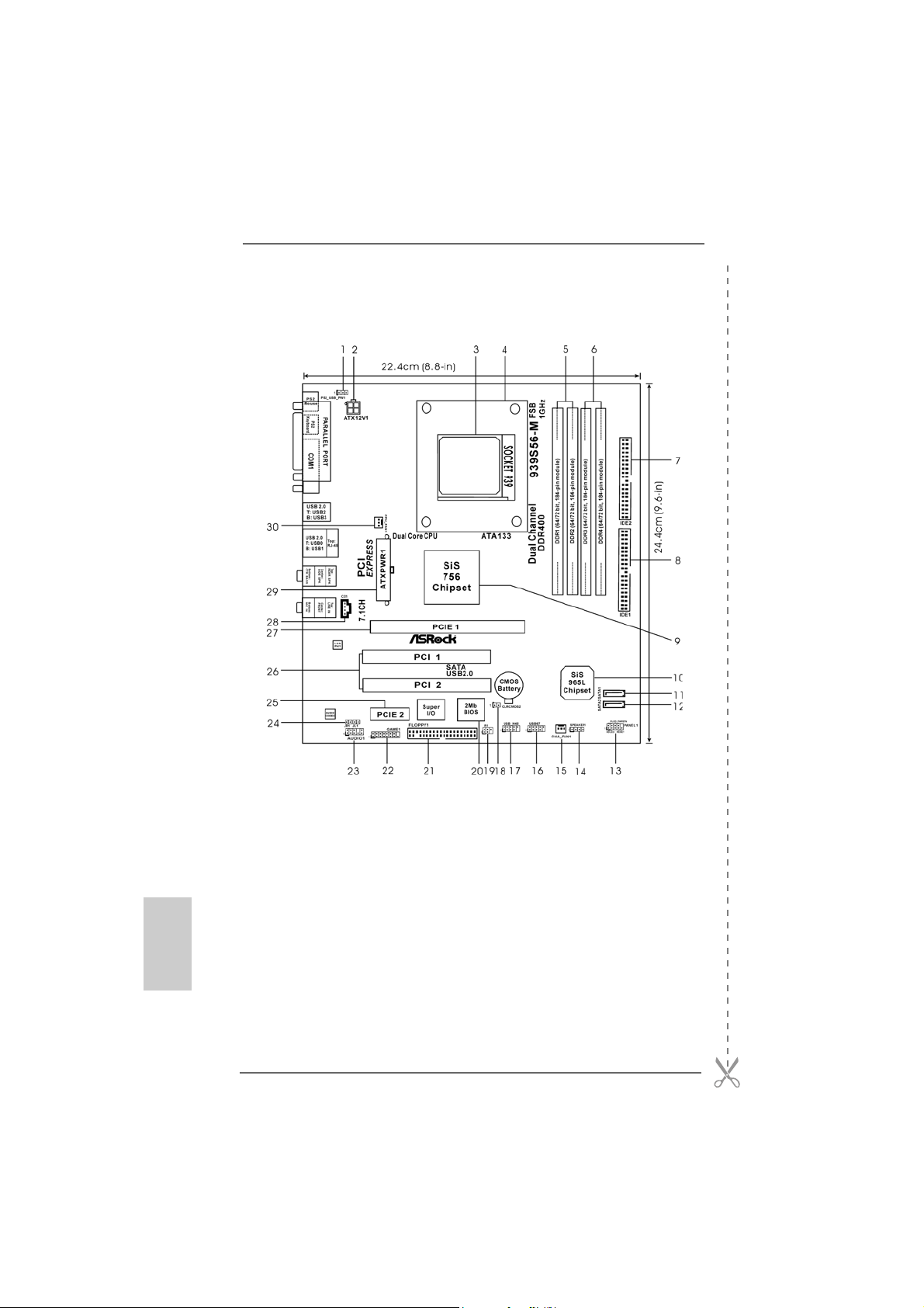
1 PS2_USB_PW1 Jumper 15 Chassis Fan Connector (CHA_FAN1)
2 A TX 12V Connector (A TX12V1) 16 USB 2.0 Header (USB67, Blue)
3 939-Pin CPU Socket 17 USB 2.0 Header (USB_H45, Blue)
4 CPU Heatsink Retention Module 18 Clear CMOS Jumper (CLRCMOS2)
5 2 x 184-pin DDR DIMM Slots 19 Infrared Module Header (IR1)
(Dual Channel A: DDR1, DDR2; Blue) 20 Flash Memory
6 2 x 184-pin DDR DIMM Slots 21 Floppy Connector (FLOPPY1)
(Dual Channel B: DDR3, DDR4; Black) 22 Game Port Header (GAME1)
7 Secondary IDE Connector (IDE2, Black) 23 Front Panel Audio Header (AUDIO1)
8 Primary IDE Connector (IDE1, Blue) 24 JR1JL1 Jumper
9 North Bridge Controller 25 PCI EXPRESS Slot (PCIE2)
10 South Bridge Controller 26 PCI Slots (PCI1 - 2)
11 Primary Serial A T A Connector (SAT A1) 27 PCI EXPRESS Slot (PCIE1)
12 Secondary Serial A T A Conne ctor (SA T A2 ) 28 Internal Audio Connector: CD1 (Black)
13 System Panel Header (P ANEL1) 29 ATX Power Connector (A TXPW R1)
14 Chassis Speaker Header (SPEAKER 1) 30 CPU Fan Connector (CPU_FAN1)
ASRock 939S56-M Motherboard
Page 3
ASRock 8CH I/OASRock 8CH I/O
ASRock 8CH I/O
ASRock 8CH I/OASRock 8CH I/O
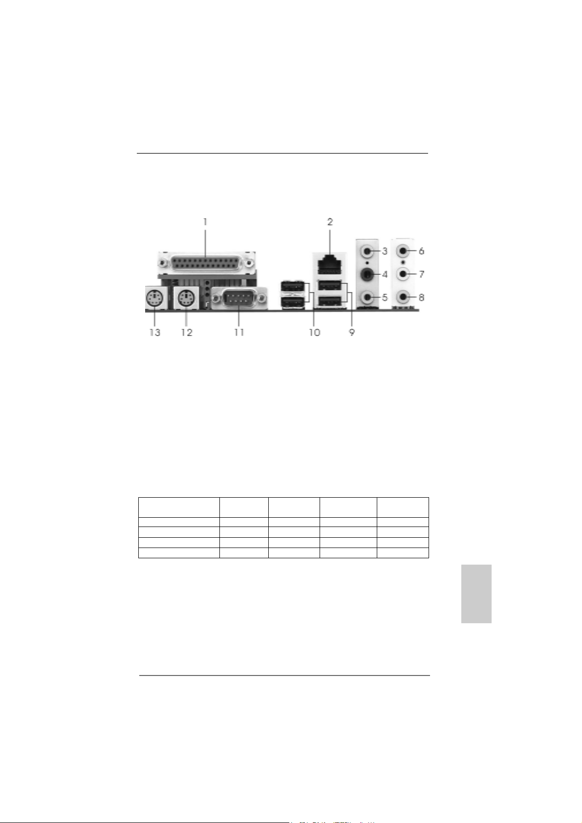
1 Parallel Port 8 Microphone (Pink)
2 RJ-45 Port 9 USB 2.0 Ports (USB01)
3 Side Speaker (Gray) 10 USB 2.0 Ports (USB23)
4 Rear Speaker (Black) 11 Serial Port: COM1
5 Central / Bass (Orange) 12 PS/2 Keyboard Port (Purple)
6 Line In (Light Blue) 13 PS/2 Mouse Port (Green)
*7 Front Speaker (Lime)
* If you use 2-channel spea ker, please connect the speaker’s plug into “Front Speaker Jack”. See
the table below for connection details in accordance with the type of speaker you use.
TABLE for Audio Output Connection
Audio Output Channels Front Speaker Rear Speaker Central / Bass Side Speaker
(No. 7) (No. 4) (No. 5) (No. 3)
2 V -- -- -4VV---6 VVV-8 VVVV
ASRock 939S56-M Motherboard
EnglishEnglish
EnglishEnglish
English
33
3
33
Page 4
1.1.
IntroductionIntroduction
1.
Introduction
1.1.
IntroductionIntroduction
Thank you for purchasing ASRock 939S56-M motherboard, a reliable motherboard
produced under ASRock’s consistently stringent quality control. It delivers excellent
performance with robust design conforming to ASRock’s commitment to quality and
endurance.
This Quick Installation Guide contains introduction of the motherboard and step-bystep installation guide. More detailed information of the motherboard can be found in
the user manual presented in the Support CD.
Because the motherboard specifications and the BIOS software might
be updated, the content of this manual will be subject to change without
notice. In case any modifications of this manual occur, the updated
version will be available on ASRock website without further notice. You
may find the latest memory and CPU support lists on ASRock website
as well.
ASRock website http://www.asrock.com
1.11.1
Package ContentsPackage Contents
1.1
Package Contents
1.11.1
Package ContentsPackage Contents
1 x ASRock 939S56-M Motherboard
(Micro ATX Form Factor: 9.6-in x 8.8-in, 24.4 cm x 22.4 cm)
1 x ASRock 939S56-M Quick Installation Guide
1 x ASRock 939S56-M Support CD
1 x Ultra ATA 66/100/133 IDE Ribbon Cable (80-conductor)
1 x 3.5-in Floppy Drive Ribbon Cable
1 x Serial ATA (SATA) Data Cable (Optional)
1 x Serial ATA (SATA) HDD Power Cable (Optional)
1 x ASRock 8CH I/O Shield
English
EnglishEnglish
EnglishEnglish
44
4
44
ASRock 939S56-M Motherboard
Page 5

1.21.2
SpecificationsSpecifications
1.2
Specifications
1.21.2
SpecificationsSpecifications
Platform: Micro ATX Form Factor: 9.6-in x 8.8-in, 24.4 cm x 22.4 cm
CPU: 939-Pin Socket Supporting AMD AthlonTM 64 / 64FX / 64 X2
Processors
Supports AMD’s Cool ‘n’ QuietTM T echnology (see CAUTION 1)
Chipsets: North Bridge: SiS 756 Chipset
FSB @ 1 GHz (2.0 GT/s) / 800MHz
Supports Untied Overclocking Technology
(see CAUTION 2)
South Bridge: SiS 965L Chipset
Supports USB 2.0, ATA 133, SATA 1.5Gb/s
Memory: 4 x DDR DIMM Slots: DDR1, DDR2, DDR3, and DDR4
Support PC3200 (DDR400) / PC2700 (DDR333) /
PC2100 (DDR266), Max. 4GB
IDE: IDE1: AT A 133 / Ultra DMA Mode 6
IDE2: AT A 133 / Ultra DMA Mode 6
Supports up to 4 IDE Devices
Serial ATA: 2 x SATA Connectors
Supports up to 2 SATA Devices at 1.5Gb/s Data Transfer Rate
Floppy Port: Supports up to 2 Floppy Disk Drives
Audio: 7.1 channels AC’97 Audio
LAN: Speed: 802.3u (10/100 Ethernet), Supports Wake-On-LAN
Hardware Monitor: CPU T emperature Sensing
Motherboard Temperature Sensing
CPU Overheat Shutdown to Protect CPU Life
(ASRock U-COP)(see CAUTION 3)
CPU Fan Ta chometer
Chassis Fan Tachometer
Voltage Monitoring: +12V, +5V, +3.3V, Vcore
PCI Slots: 2 x PCI Slots, PCI Specification 2.2
PCI EXPRESS Slots: 1 slot with PCIE x 1, 1 slot with PCIE x 16;
PCIE Specification 1.0a
USB 2.0: 8 USB 2.0 Ports:
4 Ready-to-Use USB 2.0 Ports on the I/O Panel
Plus 2 On-Board Headers Supporting 4 Extra USB 2.0 Ports
(see CAUTION 4)
ASRock 8CH I/O: 1 PS/2 Mouse Port, 1 PS/2 Keyboard Port
1 Serial Port: COM1
1 Parallel Port (ECP/EPP Support)
4 Ready-to-Use USB 2.0 Ports
1 RJ-45 Port
EnglishEnglish
EnglishEnglish
English
ASRock 939S56-M Motherboard
55
5
55
Page 6

Audio Jack: Side Speaker / Rear Speaker / Central/Bass /
Line In / Front Speaker / Microphone
(see CAUTION 5)
BIOS: AMI Legal BIOS
Supports “Plug and Play”
ACPI 1.1 Compliance Wake Up Events
SMBIOS 2.3.1 Support
CPU Frequency Stepless Control
(only for advanced users’ reference, see CAUTION 6)
OS: Microsoft® Windows® 98 SE / ME / 2000 / XP compliant
CAUTION!
1. For power-saving sake, it is strongly recommended to enable AMD’s Cool ‘n’
QuietTM technology under Windows system. See APPENDIX on page 37 of
“User Manual” in the support CD to enable AMD’s Cool ‘n’ QuietTM technology.
2. This motherboard supports Untied Overclocking Technology. FSB enjoys
better margin due to fixed PCI/PCIE buses. In other words, CPU FSB is untied
during overclocking, but PCIE and PCI buses are in the fixed mode so that
FSB can operate under a more stable overclocking environment.
3. While CPU overheat is detected, the system will automatically shutdown.
Before you resume the system, please check if the CPU fan on the motherboard
functions properly and unplug the power cord, then plug it back again. To
improve heat dissipation, remember to spray thermal grease between the
CPU and the heatsink when you install the PC system.
4. Power Management for USB 2.0 works fine under Microsoft® Windows® XP
SP1 / 2000 SP4. It may not work properly under Microsoft® Windows® 98/ ME.
5. For microphone input, this motherboard supports both stereo and mono
modes. For audio output, this motherboard supports 2-channel, 4-channel,
6-channel, and 8-channel modes. Please check the table on page 3 for
proper connection.
6. Although this motherboard offers stepless control, it is not recommended to
perform over-clocking. Frequencies other than the recommended CPU bus
frequencies may cause the instability of the system or damage the CPU.
English
EnglishEnglish
EnglishEnglish
66
6
66
ASRock 939S56-M Motherboard
Page 7
2.2.
InstallationInstallation
2.
Installation
2.2.
InstallationInstallation
Pre-installation PrecautionsPre-installation Precautions
Pre-installation Precautions
Pre-installation PrecautionsPre-installation Precautions
Take note of the following precautions before you install motherboard components or change any motherboard settings.
1. Unplug the power cord from the wall socket before touching any
component. Failure to do so may cause severe damage to the
motherboard, peripherals, and/or components.
2. To avoid damaging the motherboard components due to static
electricity, NEVER place your motherboard directly on the carpet or the like. Also remember to use a grounded wrist strap or
touch a safety grounded object before you handle components.
3. Hold components by the edges and do not touch the ICs.
4. Whenever you uninstall any component, place it on a
grounded antstatic pad or in the bag that comes with the
component.
5. When placing screws into the screw holes to secure the
motherboard to the chassis, please do not over-tighten the
screws! Doing so may damage the motherboard.
2.12.1
CPU InstallationCPU Installation
2.1
CPU Installation
2.12.1
CPU InstallationCPU Installation
Step 1. Unlock the socket by lifting the lever up to a 90° angle.
Step 2. Position the CPU directly above the socket such that its marked corner
matches the base of the socket lever.
Step 3. Carefully insert the CPU into the socket until it fits in place.
The CPU fits only in one correct orientation. DO NOT force the CPU
into the socket to avoid bending of the pins.
Step 4. When the CPU is in place, press it firmly on the socket while you push
down the socket lever to secure the CPU. The lever clicks on the side tab
to indicate that it is locked.
Step 5. Install CPU fan and heatsink. For proper installation, please kindly refer to
the instruction manuals of your CPU fan and heatsink vendors.
ASRock 939S56-M Motherboard
EnglishEnglish
EnglishEnglish
English
77
7
77
Page 8
2.2 Installation of Memory Modules (DIMM)2.2 Installation of Memory Modules (DIMM)
2.2 Installation of Memory Modules (DIMM)
2.2 Installation of Memory Modules (DIMM)2.2 Installation of Memory Modules (DIMM)
939S56-M motherboard provides four 184-pin DDR (Double Data Rate) DIMM slots,
and supports Dual Channel Memory Technology. For dual channel configuration, you
always need to install identical (the same brand, speed, size and chip-type) DDR
DIMM pair in the slots of the same color. In other words, you have to install identical
DDR DIMM pair in Dual Channel A (DDR1 and DDR2; Blue slots; see p.2 No. 5) or
identical DDR DIMM pair in Dual Channel B (DDR3 and DDR4; Black slots; see p.2
No. 6), so that Dual Cha nnel Me mory Technology can be activated. This motherboard
also allows you to install four DDR DIMMs for dual channel configuration, and please
install identical DDR DIMMs in all four slots. You may refer to the Dual Channel
Memory Configuration Table below.
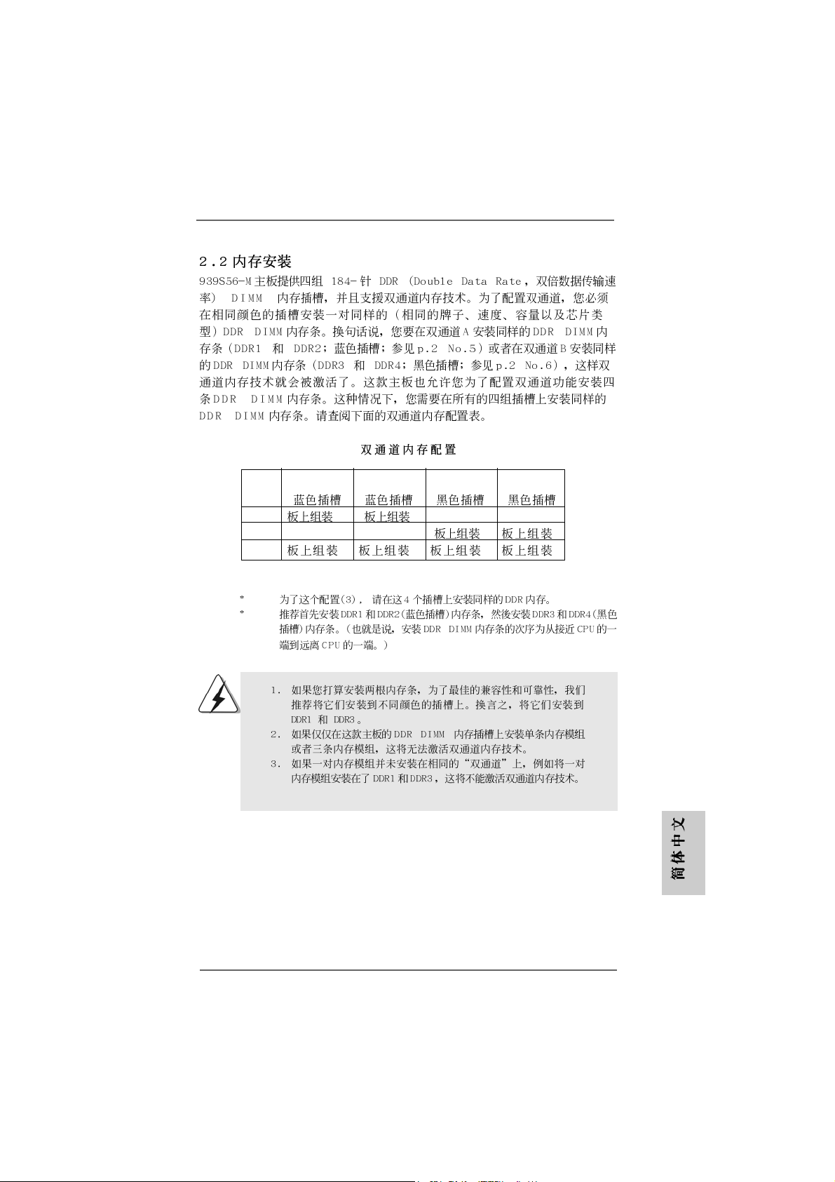
Dual Channel Memory Configurations
DDR1 DDR2 DDR3 DDR4
(Blue Slot) (Blue Slot) (Black Slot) (Black Slot)
(1) Populated Populated - (2) - - Populated Populated
(3)* Populated Populated Populated Populated
* For the configuration (3), please install identical DDR DIMMs in all four slots.
* It is recommended to install DD R1 and DD R2 (blue slots) f irst. Then to in stall
in DDR3 a nd DDR4 (bla ck slots). (That is, to populate DDR DIMM from the
near side of CPU towards to the far side of CPU.)
English
EnglishEnglish
EnglishEnglish
88
8
88
1. If you want to install two different memory modules, for optimal
compatibility and reliability, it is recommended to install them in the
slots of different color. In other words, install them either in DDR1
and DDR3.
2. If only one memory module or three memory modules are installed
in the DDR DIMM slots on this motherboard, it is unable to activate
the Dual Channel Memory T e chnology.
3. If a pair of memory modules is NOT installed in the same Dual
Channel, for example, installing a pair of memory modules in DDR1
and DDR3, it is unable to activate the Dual Channel Memory Technology .
ASRock 939S56-M Motherboard
Page 9
Installing a DIMMInstalling a DIMM
Installing a DIMM
Installing a DIMMInstalling a DIMM
Please make sure to disconnect power supply before adding or
removing DIMMs or the system components.
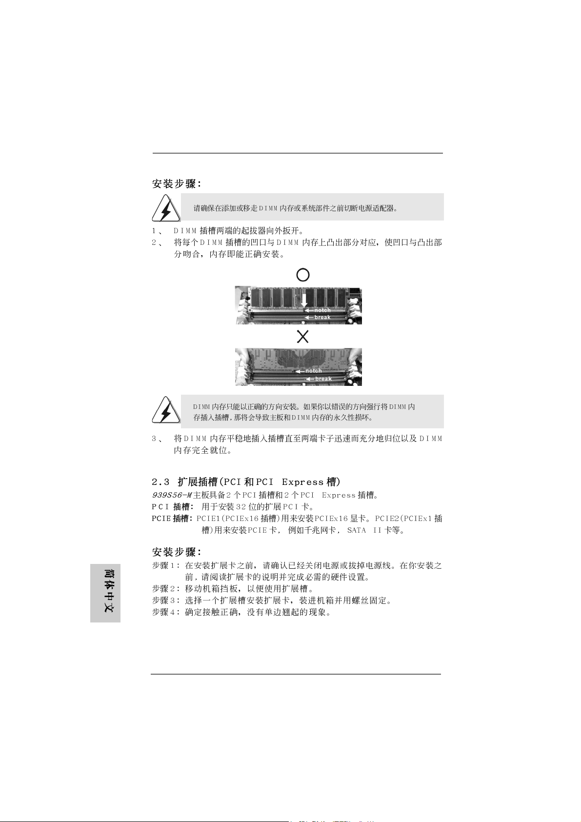
STEP 1: Unlock a DIMM slot by pressing the retaining clips outward.
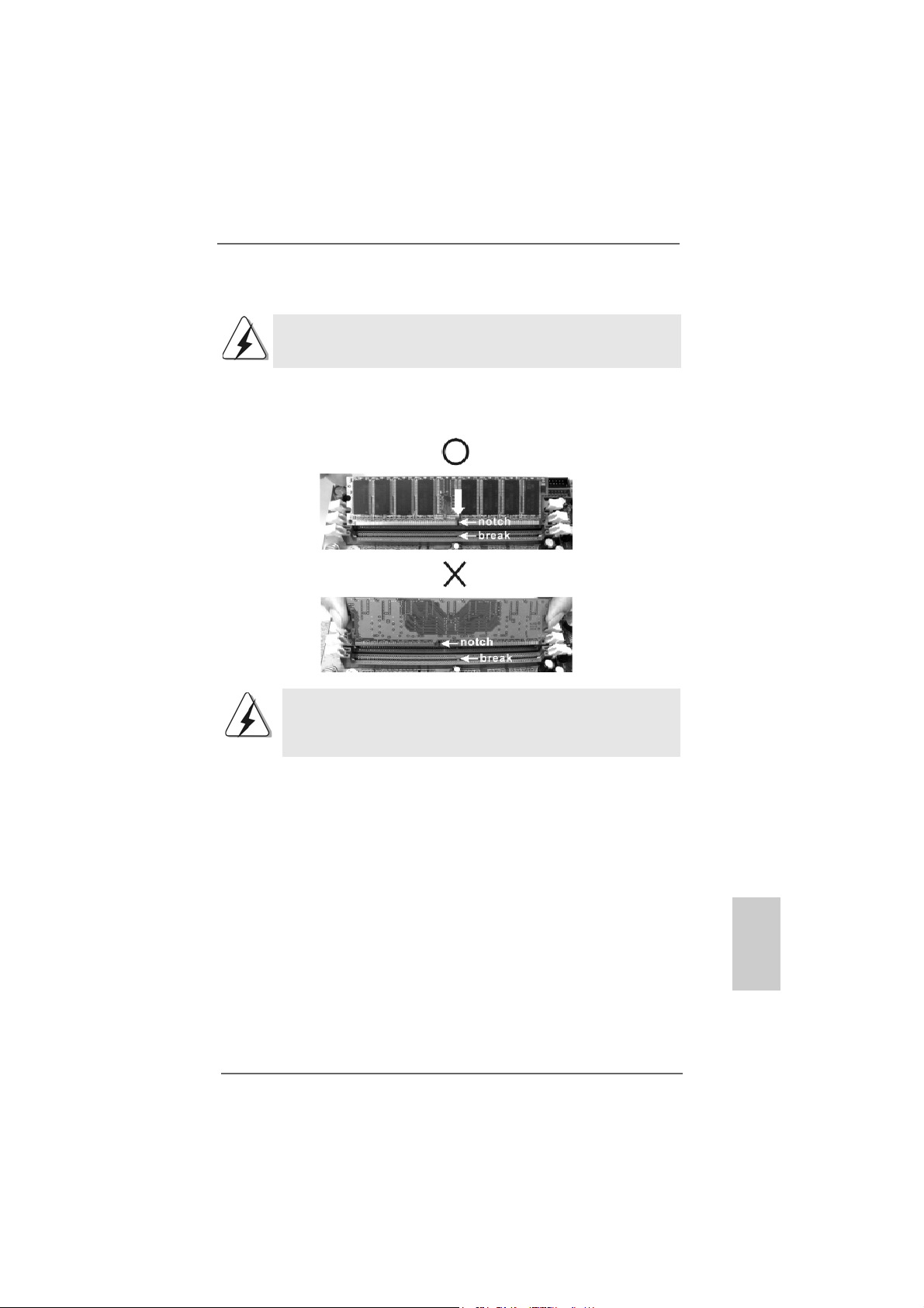
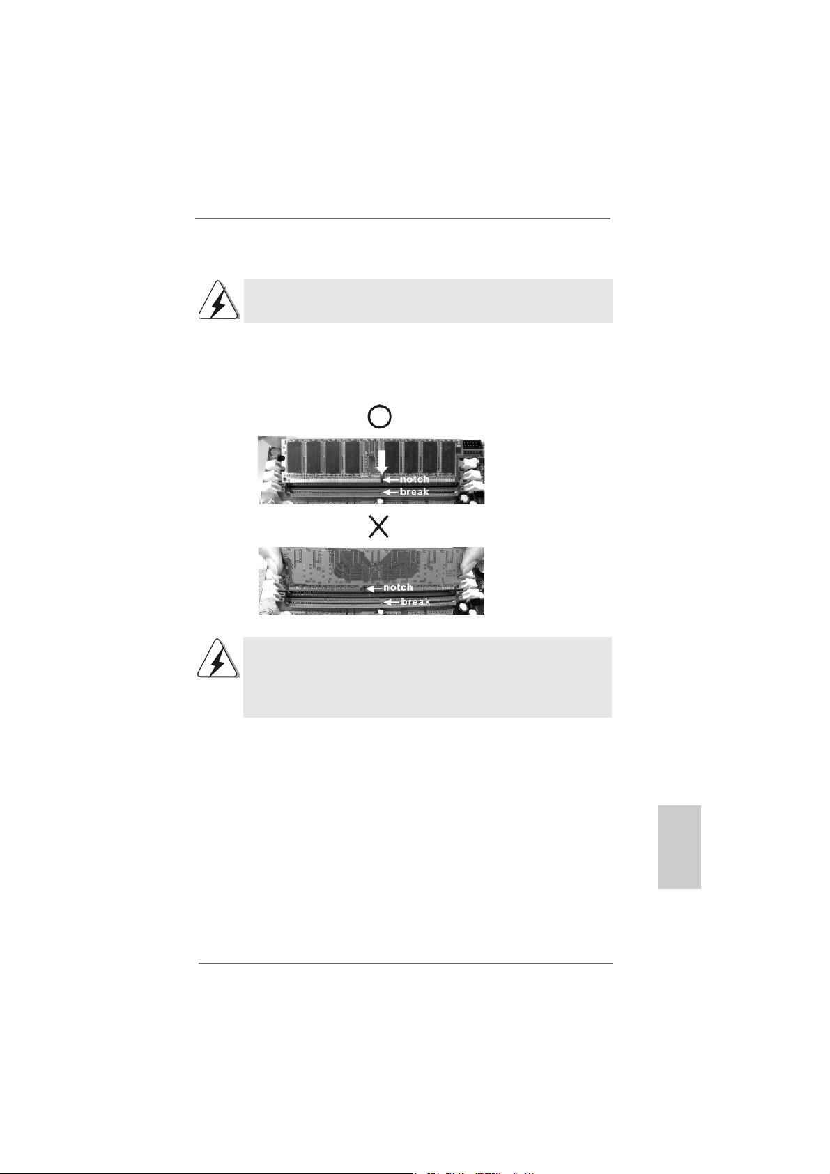
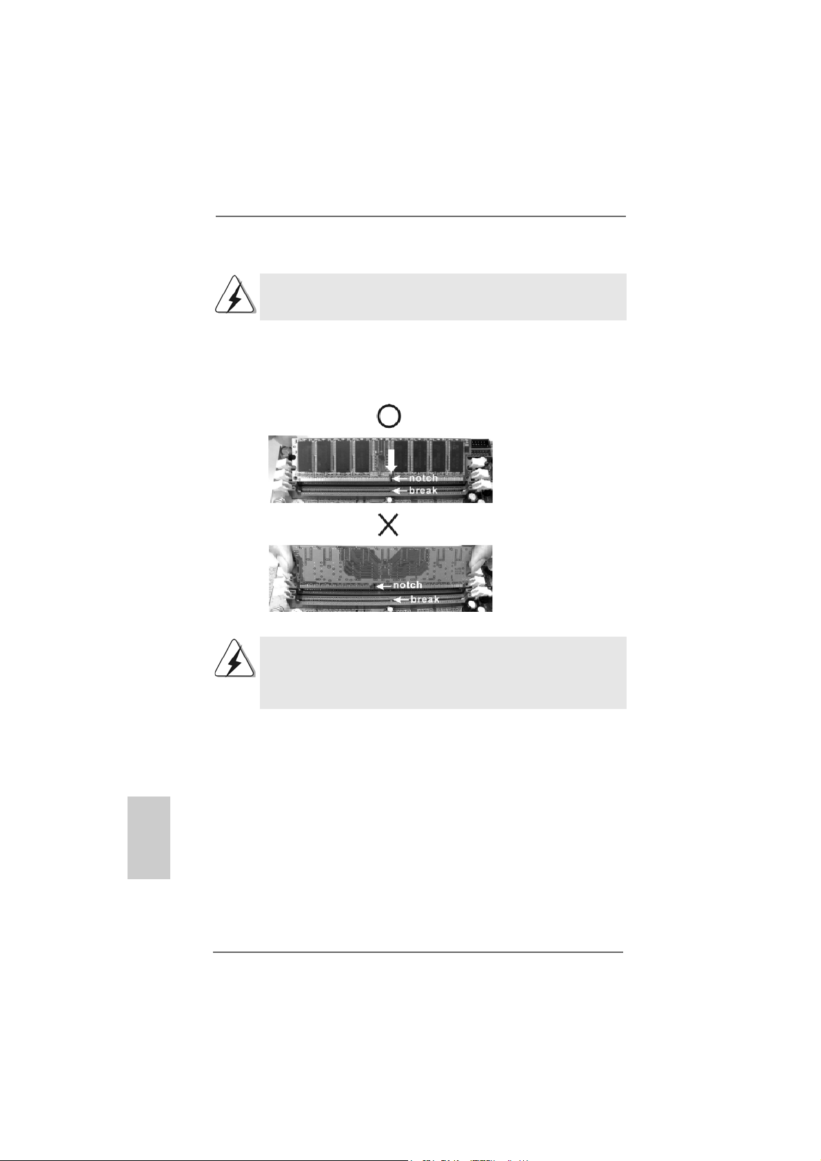
STEP 2: Align a DIMM on the slot such that the notch on the DIMM matches the
break on the slot.
The DIMM only fits in one correct orientation. It will cause permanent
damage to the motherboard and the DIMM if you force the DIMM into the
slot at incorrect orientation.
STEP 3: Firmly insert the DIMM into the slot until the retaining clips at both ends
fully snap back in place and the DIMM is properly seated.
ASRock 939S56-M Motherboard
EnglishEnglish
EnglishEnglish
English
99
9
99
Page 10

2.3 Expansion Slots (PCI and AGP Slots)2.3 Expansion Slots (PCI and AGP Slots)
2.3 Expansion Slots (PCI and AGP Slots)
2.3 Expansion Slots (PCI and AGP Slots)2.3 Expansion Slots (PCI and AGP Slots)
There are 2 PCI slots and 2 PCI Express slots on 939S56-M motherboard.
PCI Slots: PCI slots are used to install expansion cards that have the 32-bit PCI
interface.
PCIE Slots: PCIE1 (PCIE x16 slot) is used for PCI Express cards with x16 lane
width graphics cards.
PCIE2 (PCIE x1 slot) is used for PCI Express cards, such as
Gigabit LAN card, SATA II card, etc.
Installing an expansion cardInstalling an expansion card
Installing an expansion card
Installing an expansion cardInstalling an expansion card
Step 1. Before installing the expansion card, please make sure that the power
supply is switched off or the power cord is unplugged. Please read the
documentation of the expansion card and make necessary hardware
settings for the card before you start the installation.
Step 2. Remove the bracket facing the slot that you intend to use. Keep the screw
for later use.
Step 3. Align the card connector with the slot and press firmly until the card is
completely seated on the slot.
Step 4. Fasten the card to the chassis with screws.
English
EnglishEnglish
EnglishEnglish
1010
10
1010
ASRock 939S56-M Motherboard
Page 11
2.4 Jumpers Setup2.4 Jumpers Setup
2.4 Jumpers Setup
2.4 Jumpers Setup2.4 Jumpers Setup
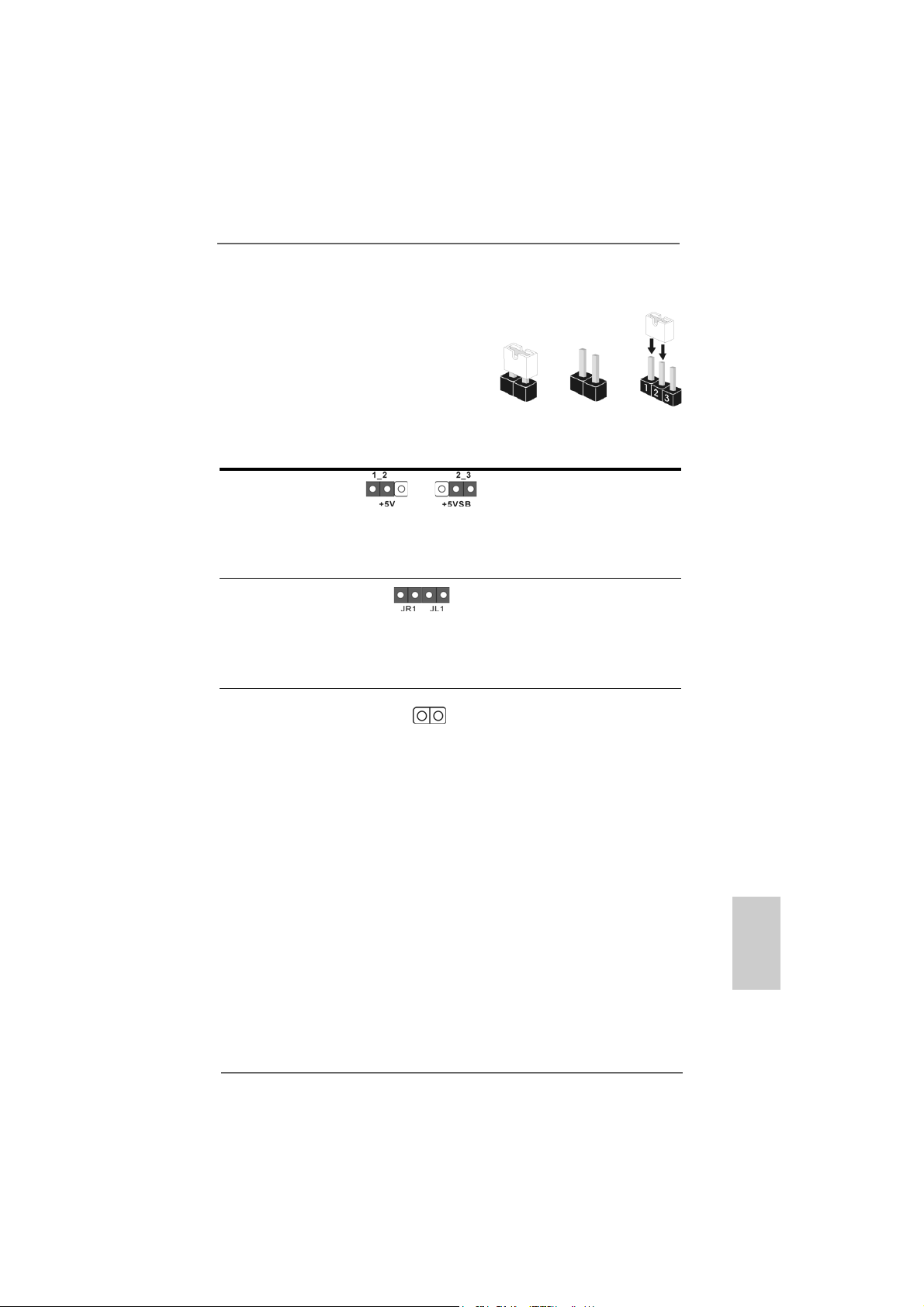
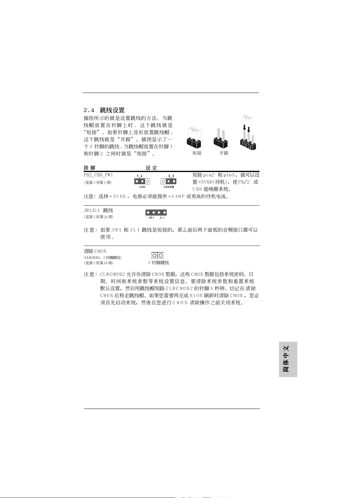
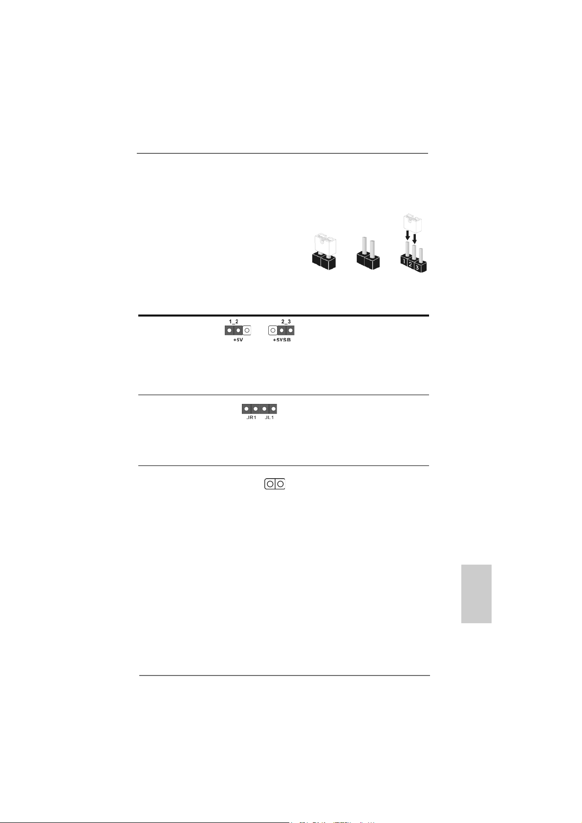
The illustration shows how jumpers are
setup. When the jumper cap is placed on
pins, the jumper is “Short”. If no jumper cap
is placed on the pins, the jumper is “Open”.
The illustration shows a 3-pin jumper whose
pin1 and pin2 are “Short” when jumper cap
is placed on these 2 pins.
Jumper Setting
PS2_USB_PW1 Short pin2, pin3 to enable
(see p.2 item 1) +5VSB (standby) for PS/2
Note: To select +5VSB, it requires 2 Amp and higher standby current provided by
power supply.
JR1JL1 Jumper
(see p.2 item 24)
Note: If JR1 and JL1 Jumpers are short, both the front panel and the rear panel
audio connectors can work.
Clear CMOS Jumper
(CLRCMOS2)
(see p.2, item 18)
2-pin jumper
Short Open
or USB wake up events.
Note: CLRCMOS2 allows you to clear the data in CMOS. The data in CMOS includes
system setup information such as system password, date, time, and system
setup parameters. To clear and reset the system parameters to default setup,
please turn off the computer and unplug the power cord from the power
supply. After waiting for 15 seconds, use a jumper cap to short 2 pins on
CLRCMOS2 for 5 seconds. However, please do not clear the CMOS right after
you update the BIOS. If you need to clear the CMOS when you just finish
updating the BIOS, you must boot up the system first, and then shut it down
before you do the clear-CMOS action.
ASRock 939S56-M Motherboard
1111
11
1111
EnglishEnglish
EnglishEnglish
English
Page 12
2.5 Connectors2.5 Connectors
2.5 Connectors
2.5 Connectors2.5 Connectors
Connectors are NOT jumpers. DO NOT place jumper caps over these
connectors. Placing jumper caps over the connectors will cause permanent damage of the motherboard!
Connector Figure Description
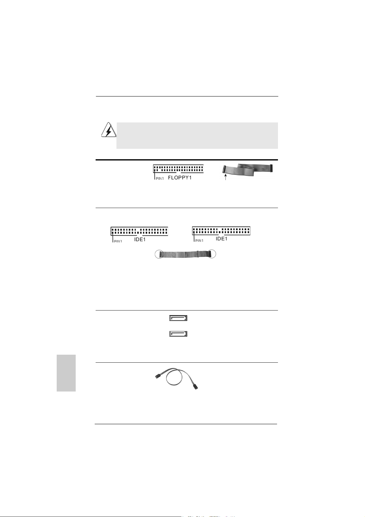
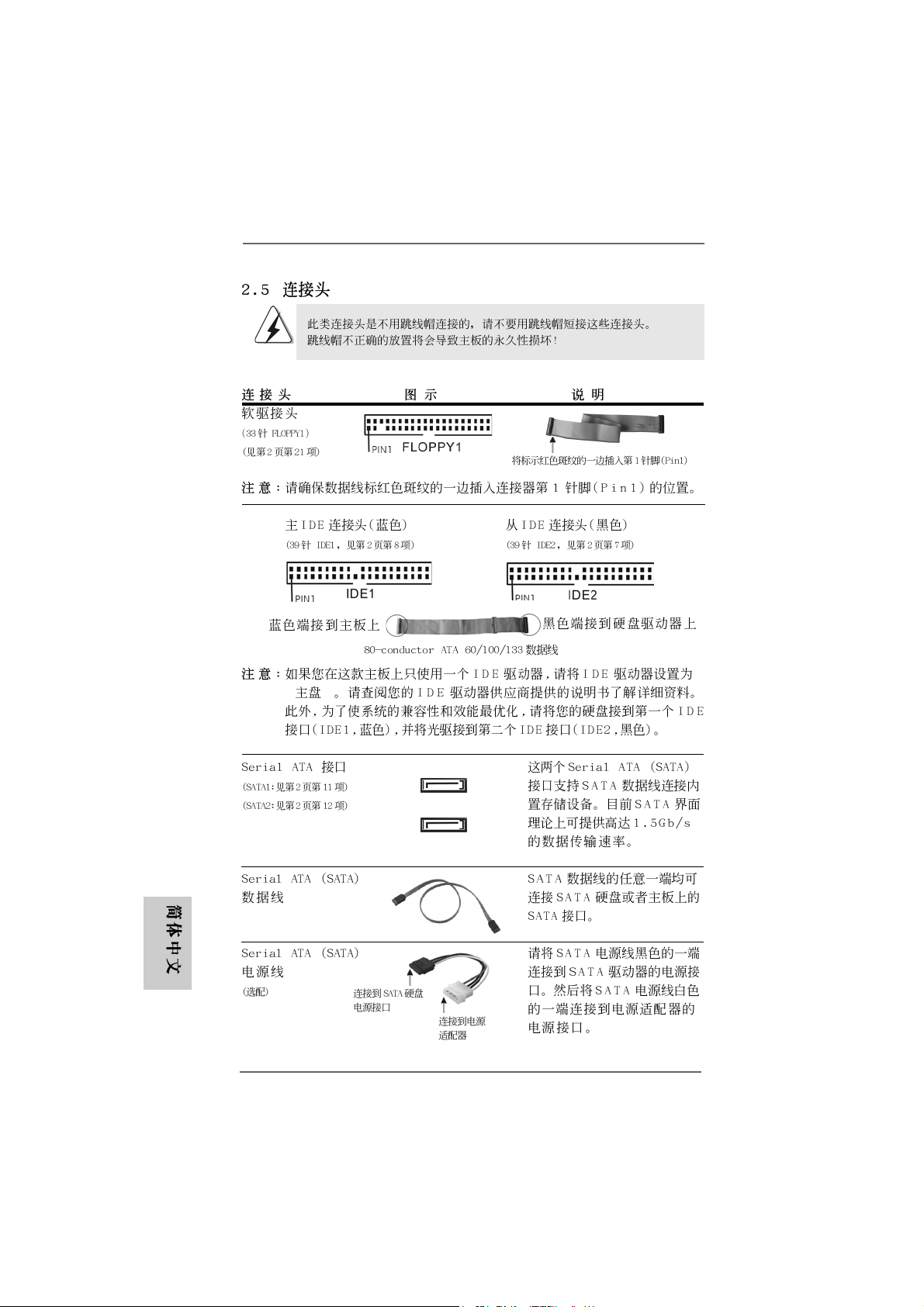
FDD Connector
(33-pin FLOPPY1)
(see p.2 item 21)
the red-striped side to Pin1
Note: Make sure the red-striped side of the cable is plugged into Pin1 side of the
connector.
Primary IDE Connector (Blue) Secondary IDE Connector (Black)
(39-pin IDE1, see p.2 item 8) (39-pin IDE2, see p.2 item 7)
English
EnglishEnglish
EnglishEnglish
1212
12
1212
connect the blue end
to the motherboard
80-conductor, ATA 66/100/133 cable
connect the black end
to the IDE devices
Note: If you use only one IDE device on this motherboard, please set the IDE
device as “Master”. Please refer to the instruction of your IDE device
vendor for the details. Besides, to optimize compatibility and performance,
please connect your hard disk drive to the primary IDE connector (IDE1,
blue) and CD-ROM to the secondary IDE connector (IDE2, black).
Serial ATA Connectors These two Serial ATA (SATA)
(SAT A1: see p.2 item 1 1) connectors support SATA data
(SAT A2: see p.2 item 12) cables for internal storage
SAT A1
SAT A2
devices. The current SATA
interface allows up to 1.5 Gb/s
data transfer rate.
Serial ATA (SATA) Either end of the SATA data
Data Cable cable can be connected to the
SATA hard disk or the SATA
connector on the motherboard.
ASRock 939S56-M Motherboard
Page 13
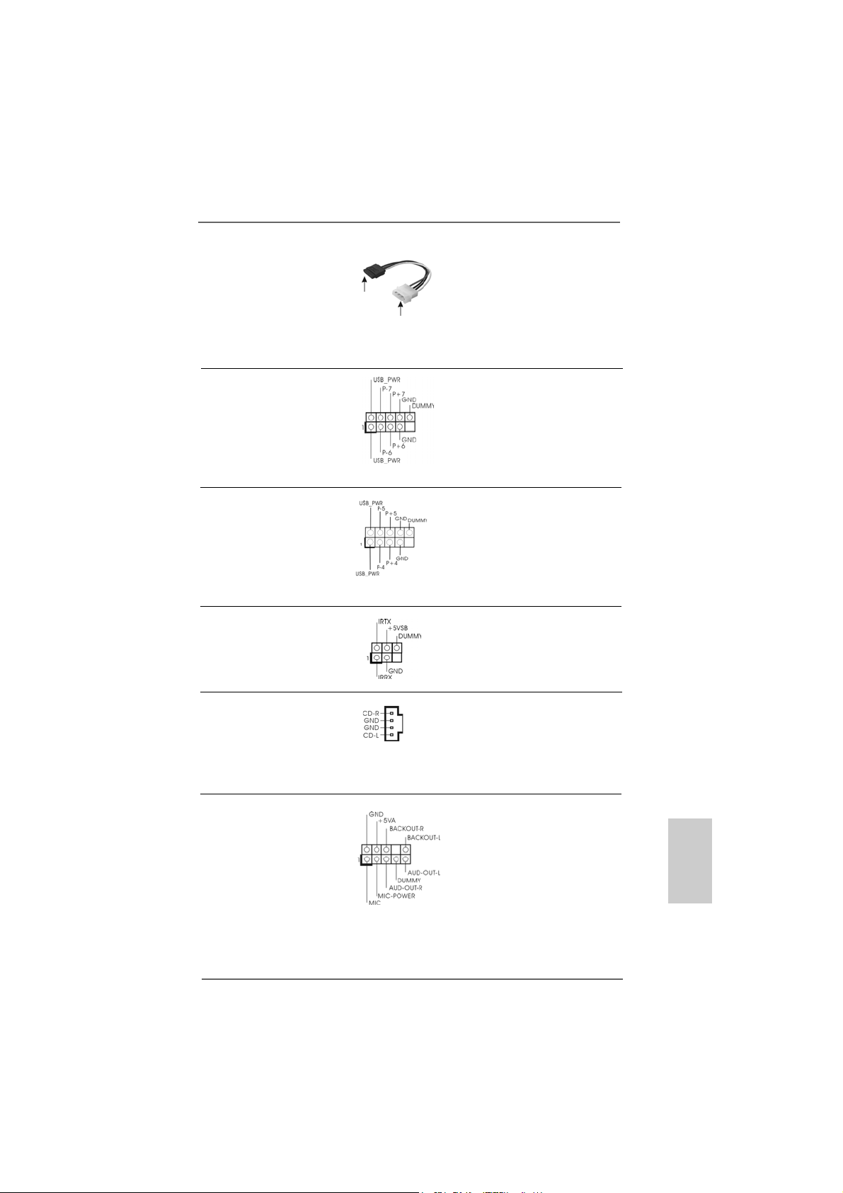
Serial ATA (SATA) Please connect the black end of
Power Cable SATA power cable to the power
(Optional) connector on the drive. Then
connect to the SAT A
HDD power connector
connect to the
power supply
connect the white end of SATA
power cable to the power
connector of the power supply.
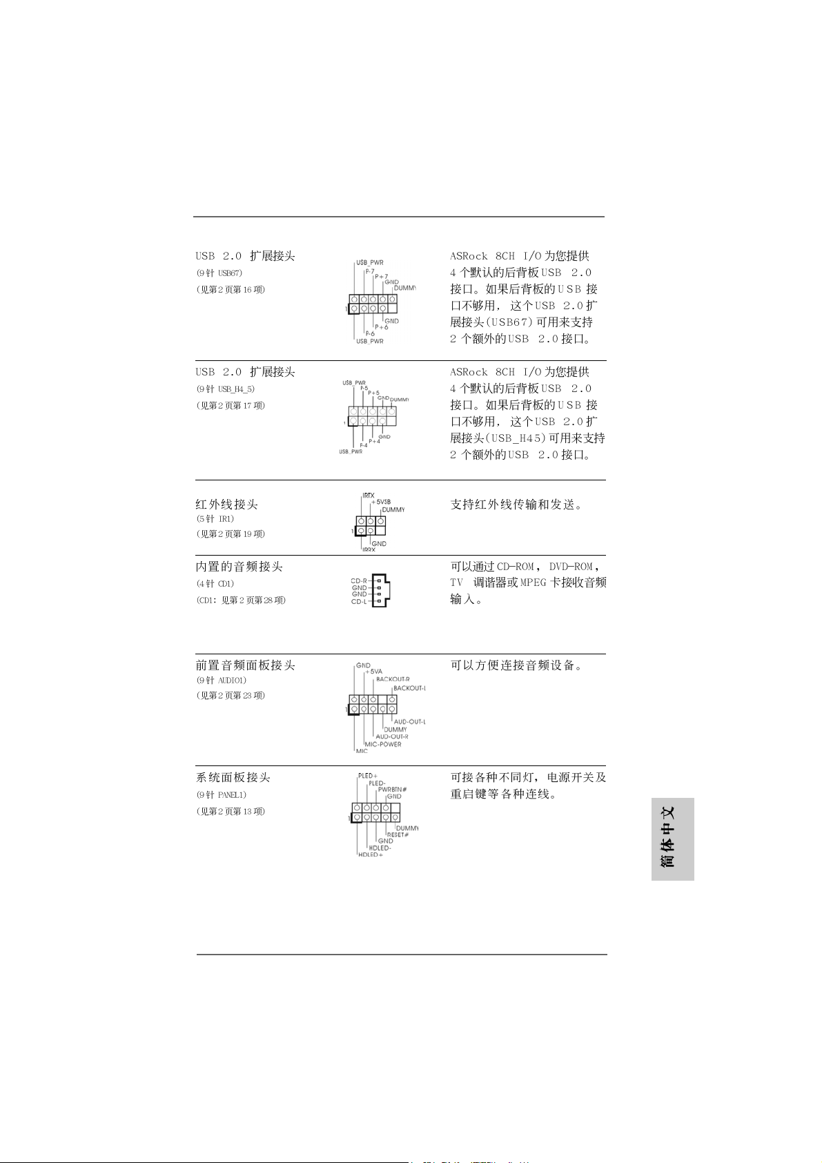
USB 2.0 Header ASRock 8CH I/OTM provides you
(9-pin USB67) 4 ready-to-use USB 2.0 ports on
(see p.2, No. 16) the rear panel. If the rear USB
ports are not sufficient, this
USB 2.0 header is available to
support 2 extra USB 2.0 ports.
USB 2.0 Header ASRock 8CH I/OTM provides you
(9-pin USB_H45) 4 ready-to-use USB 2.0 ports on
(see p.2, No. 17) the rear panel. If the rear USB
ports are not sufficient, this
USB 2.0 header is available to
support 2 extra USB 2.0 ports.
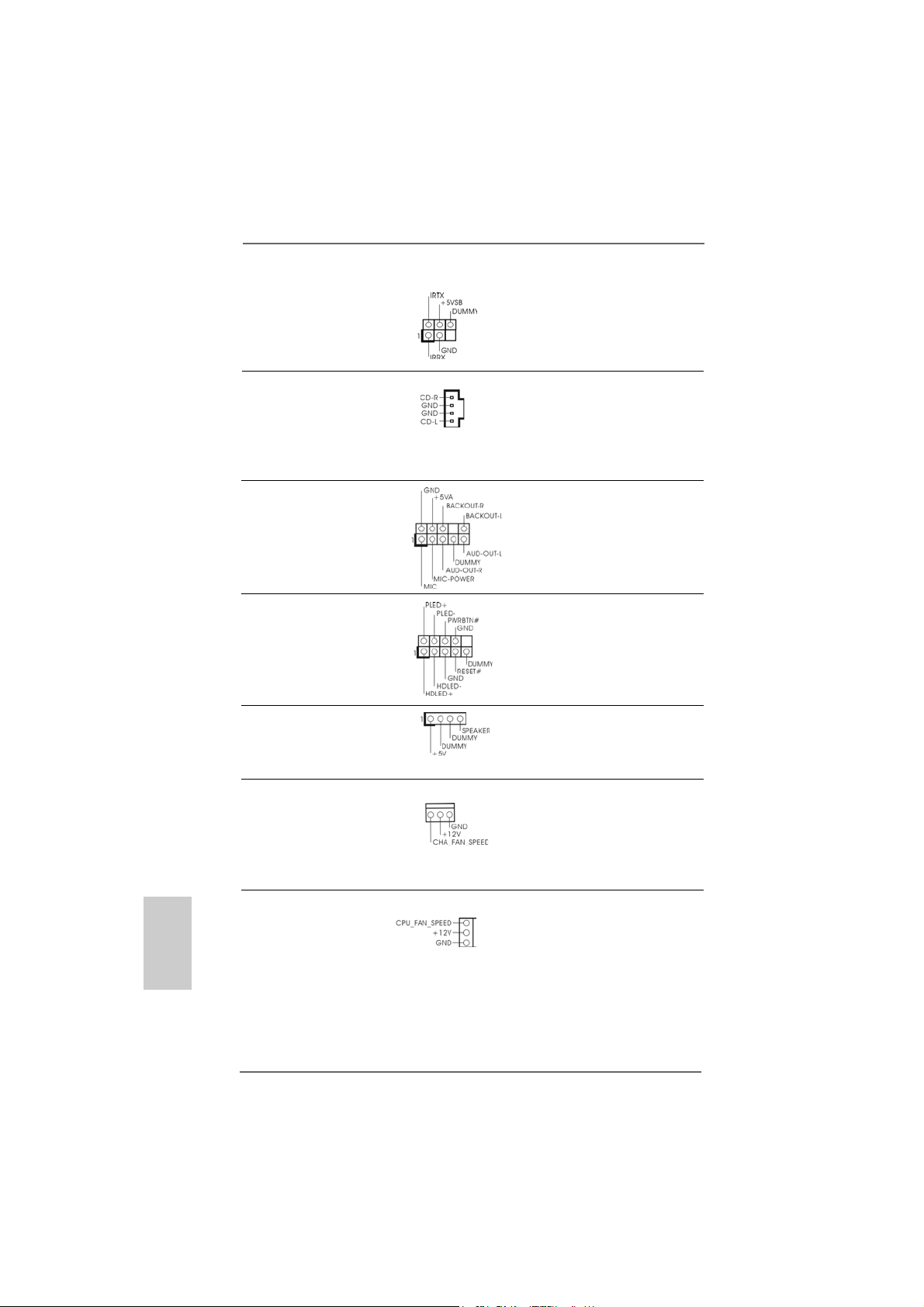
Infrared Module Header This header supports an optional
(5-pin IR1) wireless transmitting and
(see p.2, No. 19) receiving infrared module.
Internal Audio Connectors This connector allows you
(4-pin CD1) to receive stereo audio input
(CD1: see p.2, No. 28) from sound sources such as
CD1
a CD-ROM, D VD-ROM, TV
tuner card, or MPEG card.
Front Panel Audio Header This is an interface for the front
(9-pin AUDIO1) panel audio cable that allows
(see p.2, No. 23) convenient connection and
control of audio devices.
ASRock 939S56-M Motherboard
1313
13
1313
EnglishEnglish
EnglishEnglish
English
Page 14
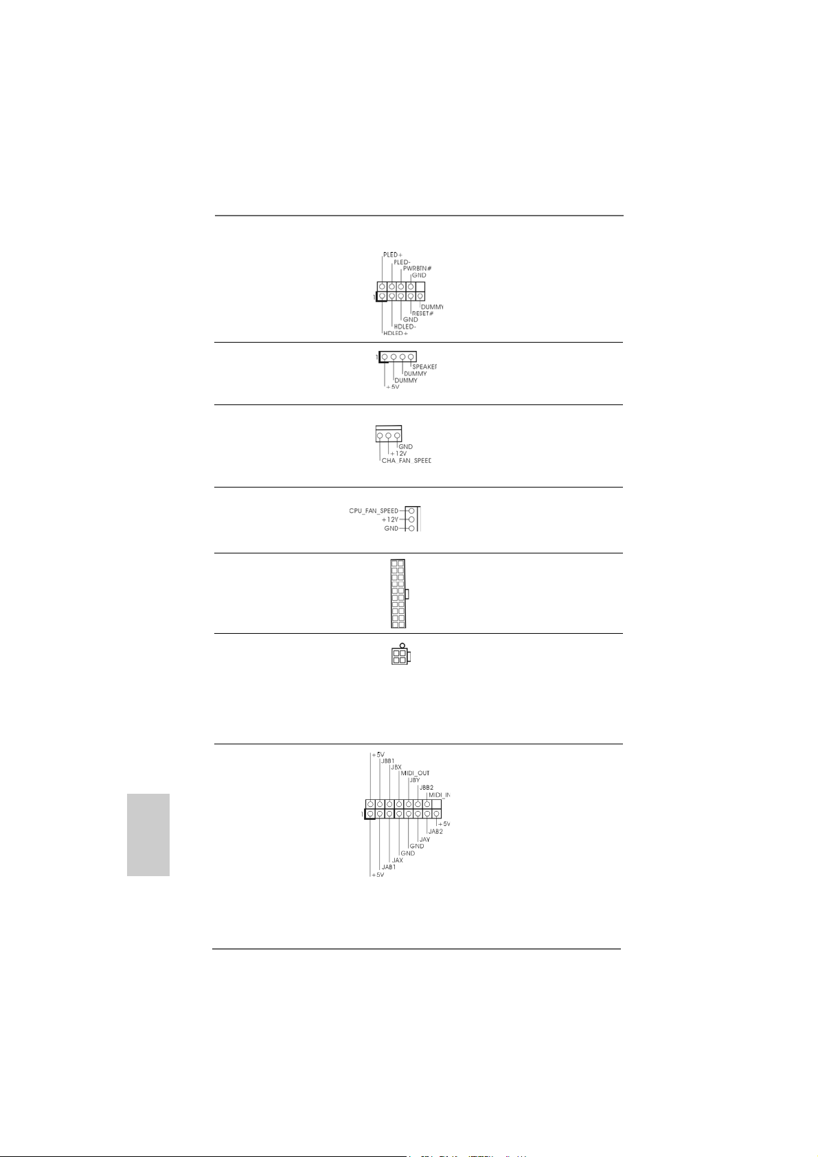
System Panel Connector This connector accommodates
(9-pin PANEL1) several system front panel
(see p.2 item 13) functions.
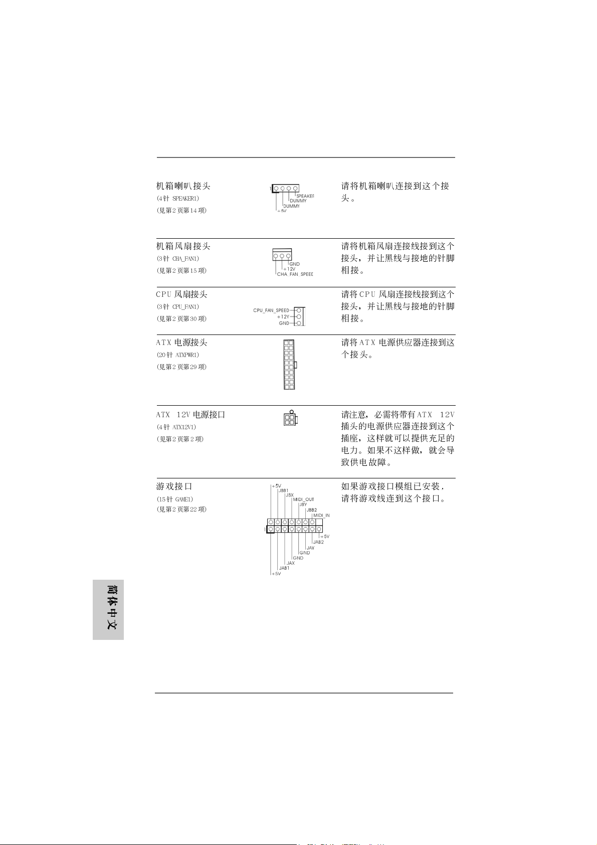
Chassis Speaker Connector Please connect the chassis
(4-pin SPEAKER 1) speaker to this connector.
(see p.2 item 14)
Chassis Fan Connector Please connect a chassis fan
(3-pin CHA_FAN1) cable to this connector and
(see p.2 item 15) match the black wire to the
ground pin.
CPU Fan Connector Please connect a CPU fan cable
(3-pin CPU_FAN1) to this connector and match the
(see p.2 item 30) black wire to the ground pin.
ATX Power Connector Please connect an ATX power
(20-pin ATXPW R1) supply to this connector.
(see p.2 item 29)
ATX 12V Connector Please note that it is necessary
(4-pin A TX12V1) to connect a power supply with
(see p.2 item 2) ATX 12V plug to this connector
so that it can provides sufficient
power. Failing to do so will cause
the failure to power up.
English
EnglishEnglish
EnglishEnglish
Game Connector Connect a Game cable to this
(15-pin GAME1) connector if the Game port
(see p.2 item 22) bracket is installed.
1414
14
1414
ASRock 939S56-M Motherboard
Page 15
2.62.6
Serial ASerial A
2.6
Serial A
2.62.6
Serial ASerial A
This motherboard supports Serial ATA (SATA) hard disks and RAID functions. This
section will guide you to install the SATA hard disks.
STEP 1: Install the SATA hard disks into the drive bays of your chassis.
STEP 2: Connect the SATA power cable to the SATA hard disk.
STEP 3: Connect one end of the SATA data cable to the motherboard’s SATA
STEP 4: Connect the other end of the SATA data cable to the SATA hard disk.
TT
A (SAA (SA
TT
T
TT
connector.
1. If you plan to use RAID 0, RAID 1, or JBOD functions on SATA, SATA
HDDs must be operated in “RAID” mode.
2. “RAID” and “non-RAID” mode are options under “SATA Operation Mode” in
BIOS setup. Please refer to page 28 of User Manual in the support CD for
details. They need different drivers during actual operation.
A) Hard Disks InstallationA) Hard Disks Installation
A (SA
T
A) Hard Disks Installation
A (SAA (SA
TT
A) Hard Disks InstallationA) Hard Disks Installation
2.7 Hot Plug F2.7 Hot Plug F
2.7 Hot Plug F
2.7 Hot Plug F2.7 Hot Plug F
939S56-M motherboard supports Hot Plug function for SATA devices.
What is Hot Plug Function?
unction for SAunction for SA
unction for SA
unction for SAunction for SA
If the SATA HDDs are NOT set for RAID configuration, it is called “Hot
Plug” for the action to insert and remove the SATA HDDs while the
system is still power-on and in working condition. However, please note
that it cannot perform Hot Plug if the OS has been installed into the SATA
HDD.
WARNING!
Although this motherboard supports Hot Plug function for SATA devices,
there are still some limitation. Please ensure to read the instruction in the
Support CD before you use Hot Plug function. Failure to do so may lose
the data in the SATA HDDs or damage the SATA HDDs. For the detailed
instruction, please refer to the document in the Support CD at the
following path:
..\ RAID BIOS Setting Utility
TT
A HDDsA HDDs
T
A HDDs
TT
A HDDsA HDDs
EnglishEnglish
EnglishEnglish
English
ASRock 939S56-M Motherboard
1515
15
1515
Page 16

2.82.8
Making a SAMaking a SA
2.8
Making a SA
2.82.8
Making a SAMaking a SA
“RAID” Mode“RAID” Mode
“RAID” Mode
“RAID” Mode“RAID” Mode
If you want to install Windows 2000, Windows XP, or Windows XP 64-bit OS on your
SATA HDDs with RAID functions, you will need to make a SATA driver before you
start the OS installation.
STEP 1: Insert the ASRock Support CD into your optical drive to boot your system.
(Do NOT insert any floppy diskette into the floppy drive at this moment!)
STEP 2: During POST at the beginning of system boot-up, press <F11> key, and
then a window for boot devices selection appears. Please select CDROM as the boot device.
STEP 3: When you see the message on the screen, “Do you want to generate
Serial ATA driver diskette [YN]?”, press <Y>.
STEP 4: Then you will see these messages,
Please insert a diskette into the floppy drive.
WARNING! Formatting the floppy diskette will
lose ALL data in it!
Start to format and copy files [YN]?
Please insert a floppy diskette into the floppy drive, and press <Y>.
STEP 5: The system will start to format the floppy diskette and copy SATA drivers
into the floppy diskette.
Once you have the SATA driver diskette ready, you may start to install Windows 2000
/ Windows XP / Windows XP 64-bit on your system directly without setting the RAID
configuration on your system, or you may start to use “SiS RAID BIOS Setting Utility”
to set RAID 0 / RAID 1 / JBOD configuration before you install the OS. Before you start
to configure the RAID function, you need to check the installation guide in the Support
CD for proper configuration. Please find the document, “Guide to SATA Hard Disks
Installation and RAID Configuration”, at the following path in the Support CD:
.. \ RAID BIOS Setting Utility
TT
A Driver DiskA Driver Disk
T
A Driver Disk
TT
A Driver DiskA Driver Disk
ette Fette F
ette F
ette Fette F
or SAor SA
TT
A Operation inA Operation in
or SA
T
A Operation in
or SAor SA
TT
A Operation inA Operation in
English
EnglishEnglish
EnglishEnglish
1616
16
1616
You may also set the RAID configuration by using “SiS RAID Utility for Windows” in
Windows environment. Please refer to the document in the Support CD, “Guide to SiS
RAID Utility for Windows”, which is located in the folder at the following path:
.. \ RAID Utility for Windows
2.92.9
SASA
TT
2.9
2.92.9
If you want to install Windows 2000, Windows XP, or Windows XP 64-bit OS on your
SATA HDDs operating in non-RAID mode, you don’t need to make a SATA driver
diskette before OS installation.
A Operating in “non-RAID” ModeA Operating in “non-RAID” Mode
SA
T
A Operating in “non-RAID” Mode
SASA
TT
A Operating in “non-RAID” ModeA Operating in “non-RAID” Mode
Windows 98 SE and Windows ME must be installed by SATA operating in
RAID mode, and you don’t need to make a SATA driver diskette for these
two OS before OS installation.
ASRock 939S56-M Motherboard
Page 17

3. BIOS Information3. BIOS Information
3. BIOS Information
3. BIOS Information3. BIOS Information
The Flash Memory on the motherboard stores BIOS Setup Utility. When you start up
the computer, please press <F2> during the Power-On-Self-Test (POST) to enter
BIOS Setup utility; otherwise, POST continues with its test routines. If you wish to
enter BIOS Setup after POST, please restart the system by pressing <Ctl> + <Alt> +
<Delete>, or pressing the reset button on the system chassis.
The BIOS Setup program is designed to be user-friendly. It is a menu-driven program,
which allows you to scroll through its various sub-menus and to select among the
predetermined choices. For the detailed information about BIOS Setup, please refer
to the User Manual (PDF file) contained in the Support CD.
4. Software Suppor4. Software Suppor
4. Software Suppor
4. Software Suppor4. Software Suppor
This motherboard supports various Microsoft® Windows® operating systems: 98 SE/
ME / 2000 / XP. The Support CD that came with the motherboard contains necessary
drivers and useful utilities that will enhance motherboard features.
To begin using the Support CD, insert the CD into your CD-ROM drive. It will display
the Main Menu automatically if “AUTORUN” is enabled in your computer. If the Main
Menu does not appear automatically, locate and double-click on the file “ASSETUP.
EXE” from the “BIN” folder in the Support CD to display the menus.
t CD informationt CD information
t CD information
t CD informationt CD information
EnglishEnglish
EnglishEnglish
English
ASRock 939S56-M Motherboard
1717
17
1717
Page 18
1818
18
1818
®
®
ASRock 939S56-M Motherboard
Page 19
™
‘ ’ ™
®
®
ASRock 939S56-M Motherboard
‘ ’
1919
19
1919
Page 20
2020
20
2020
ASRock 939S56-M Motherboard
Page 21
DDR1 DDR2 DDR3 DDR4
( )( )( )( )
(1) - (2) - -
(3)
ASRock 939S56-M Motherboard
2121
21
2121
Page 22
2222
22
2222
ASRock 939S56-M Motherboard
Page 23
ASRock 939S56-M Motherboard
2323
23
2323
Page 24
2424
24
2424
“ ”
SAT A1
SAT A2
ASRock 939S56-M Motherboard
Page 25
CD1
ASRock 939S56-M Motherboard
2525
25
2525
Page 26
2626
26
2626
ASRock 939S56-M Motherboard
Page 27
“ ”
\
ASRock 939S56-M Motherboard
“ ”
2727
27
2727
Page 28
2828
28
2828
“ ”
“
”
“ ”
“
”
ASRock 939S56-M Motherboard
Page 29
® ®
ASRock 939S56-M Motherboard
2929
29
2929
Page 30
1. Einführung1. Einführung
1. Einführung
1. Einführung1. Einführung
Wir danken Ihnen für den Kauf des ASRock 939S56-M Motherboard, ein zuverlässiges
Produkt, welches unter den ständigen, strengen Qualitätskontrollen von ASRock
gefertigt wurde. Es bietet Ihnen exzellente Leistung und robustes Design, gemäß der
Verpflichtung von ASRock zu Qualität und Halbarkeit.
Diese Schnellinstallationsanleitung führt in das Motherboard und die schrittweise
Installation ein. Details über das Motherboard finden Sie in der
Bedienungsanleitung auf der Support-CD.
Da sich Motherboard-Spezifikationen und BIOS-Software verändern können,
kann der Inhalt dieses Handbuches ebenfalls jederzeit geändert werden. Für
den Fall, dass sich Änderungen an diesem Handbuch ergeben, wird eine neue
Version auf der ASRock-Website, ohne weitere Ankündigung, verfügbar sein.
Die jeweils neueste Liste der unterstützten Speichertypen CPUs finden Sie
ebenfalls auf der Webseite von ASRock.
ASRock-Website: http://www.asrock.com
1.1 Kartoninhalt
ASRock 939S56-M Motherboard
(Micro ATX-Formfaktor: 24.4 cm x 22.4 cm; 9.6 Zoll x 8.8 Zoll)
ASRock 939S56-M Schnellinstallationsanleitung
ASRock 939S56-M Support-CD
Ein 80-adriges Ultra-ATA 66/100/133 IDE-Flachbandkabel
Ein Flachbandkabel für ein 3,5-Zoll-Diskettenlaufwerk
Ein Seriell-ATA- (SATA) Datenkabel (Option)
Ein Seriell-ATA (SATA) Festplattennetzkabel (Option)
Ein ASRock 8CH I/O
Deutsch
DeutschDeutsch
DeutschDeutsch
3030
30
3030
ASRock 939S56-M Motherboard
Page 31

1.21.2
SpezifikationenSpezifikationen
1.2
Spezifikationen
1.21.2
SpezifikationenSpezifikationen
Plattform: Micro ATX-Formfaktor: 24.4 cm x 22.4 cm; 9.6 Zoll x 8.8 Zoll
CPU: 939-pol. Sockel, unterstützt AMD AthlonTM 64 / 64FX / 64 X2-
Prozessoren; Unterstützt die AMD Cool ‘n’ QuietTMTechnologie (Siehe VORSICHT 1)
Chipsatz: North Bridge:
SiS® 756, FSB @ 1GHz (2.0GT/s) / 800MHz,
Unterstützt Untied-Übertaktungstechnologie
(Siehe VORSICHT 2)
South Bridge:
SiS® 965L, unterstützt USB2.0, ATA133, SATA 1.5Gb/s
Speicher: 4 Steckplätze für DDR: DDR1, DDR2, DDR3 und DDR4
PC3200 (DDR400) / PC2700 (DDR333) /
PC2100 (DDR266) für 4 DD R DIMM Slots Max. 4GB
HDD: IDE1: AT A 133 / Ultra DMA Mode 6
IDE2: ATA 133 / Ultra DMA Mode 6
Unterstützt bis 4 IDE-Geräte
Seriell-ATA: 2 SATA-Anschlüsse, unterstützt bis 1.5 Gb/s
Datenübertragungsrate
FDD: Unterstützt bis 2 Diskettenlaufwerke
Audio: 7.1 Kanal AC’97 Audio
LAN: Speed: 802.3u (10/100 Ethernet), unterstützt Wake-On-LAN
Hardware Monitor: Überwachung der CPU-Temperatur
Motherboardtemperaturerkennung
CPU-Überhitzungsschutz durch rechtzeitigen
Systemshutdown (ASRock U-COP)(Siehe VORSICHT 3)
Drehzahlmessung für CPU-Lüfter
Drehzahlmessung für Gehäuselüfter
Spannungsüberwachung: +12V, +5V, +3.3V, Vcore
PCI-Slots: 2 slots nach PCI-Spezifikation 2.2
PCIE-Slots: 1 Steckplatz mit PCIE x 1, 1 Steckplatz mit PCIE x 16;
PCIE-Spezifikation 1.0a
USB 2.0: 8 USB 2.0-Anschlüsse:
einschließlich 4 Standard-USB 2.0-Anschlüsse auf der
Rückseite, plus einem Header zur Unterstützung 4
zusätzlicher USB 2.0-Anschlüsse (siehe VORSICHT 4)
ASRock 8CH I/O: 1 PS/2-Mausanschluss, 1 PS/2-Tastaturanschluss,
1 serieller port: COM 1,
1 paralleler port (Unterstützung für ECP / EPP),
4 betriebsfertigen USB 2.0-Anschlüsse,
1 RJ-45 port,
ASRock 939S56-M Motherboard
3131
31
3131
DeutschDeutsch
DeutschDeutsch
Deutsch
Page 32

Deutsch
DeutschDeutsch
DeutschDeutsch
Audio Jack: Side Speaker / Rear Speaker / Central/Bass /
Line In / Front Speaker / Microphone
(see CAUTION 5)
BIOS: AMI legal BIOS mit Unterstützung für “Plug a nd Play”;
ACPI 1.1-We ckfunktionen; SMBIOS 2.3.1;
Schrittloser CPU-Frequenz-Kontrolle (Nur für erfahrene
Anwender empfohlen, siehe VORSICHT 6)
Betriebssysteme: Unterstützt Microsoft® Windows® 98 SE / ME / 2000 / XP
VORSICHT!
1. Um Energie zu sparen, wird dringendst empfohlen, die Cool ‘n’ Quiet™ Technologie von AMD im Windows-System zu aktivieren. Siehe ANHANG
auf Seite 37 des “Handbuchs” auf der Support-CD für Hinweise zur
Aktivierung der Cool ‘n’ Quiet™-Technologie von AMD.
2. Dieses Motherboard unterstützt die Untied-Übertaktungstechnologie. Beim
Übertakten wird der FSB von den PCIE- und PCI-Bussen abgekoppelt. Mit
anderen Worten: Der CPU-FSB wird beim Übertakten abgekoppelt, PCIEund PCI-Bus aber arbeiten im fixierten Modus, so dass der FSB in einer
stabileren Übertaktungsumgebung arbeiten kann.
3. Wird eine Überhitzung der CPU registriert, führt das System einen
automatischen Shutdown durch. Bevor Sie das System neu starten, prüfen
Sie bitte, ob der CPU-Lüfter am Motherboard richtig funktioniert, und
stecken Sie bitte den Stromkabelstecker aus und dann wieder ein. Um die
Wärmeableitung zu verbessern, bitte nicht vergessen, etwas Wärmeleitpaste
zwischen CPU und Kühlkörper zu sprühen.
4. Das Power Management für USB 2.0 arbeitet unter Microsoft
XP SP1/2000 SP4 einwandfrei. Unter Microsoft® Windows® 98/ME könnte
es dagegen zu Störungen kommen.
5. For microphone input, this motherboard supports both stereo and mono
modes. For audio output, this motherboard supports 2-channel, 4-channel,
6-channel, and 8-channel modes. Please check the table on page 3 for
proper connection.
6. Obwohl dieses Motherboard stufenlose Steuerung bietet, wird
Overclocking nicht empfohlen. Frequenzen, die von den empfohlenen
CPU-Busfrequenzen abweichen, können Instabilität des Systems
verursachen oder die CPU beschädigen.
®
Windows
®
3232
32
3232
ASRock 939S56-M Motherboard
Page 33

2. Installation2. Installation
2. Installation
2. Installation2. Installation
Sicherheitshinweise vor der MontageSicherheitshinweise vor der Montage
Sicherheitshinweise vor der Montage
Sicherheitshinweise vor der MontageSicherheitshinweise vor der Montage
Bitte nehmen Sie die folgende Sicherheitshinweise zur Kenntnis,
bevor Sie das Motherboard einbauen oder Veränderungen an den
Einstellungen vornehmen.
1. Trennen Sie das System vom Stromnetz, bevor Sie eine
Systemkomponente berühren, da es sonst zu schweren Schäden am
Motherboard oder den sonstigen internen, bzw. externen Komponenten
kommen kann.
2. Um Schäden aufgrund von statischer Elektrizität zu vermeiden, das
Motherboard NIEMALS auf einen Teppich o.ä.legen. Denken Sie außerem
daran, immer ein geerdetes Armband zu tragen oder ein geerdetes Objekt
aus Metall zu berühren, bevor Sie mit Systemkomponenten hantieren.
3. Halten Sie Komponenten immer an den Rändern und vermeiden Sie
Berührungen mit den ICs.
4. Wenn Sie Komponenten ausbauen, legen Sie sie immer auf eine
antistatische Unterlage, oder zurück in die Tüte, mit der die Komponente
geliefert wurde.
5. Wenn Sie das Motherboard mit den Schrauben an dem Computergehäuse
befestigen, überziehen Sie bitte die Schrauben nicht! Das Motherboard
kann sonst beschädigt werden.
2.1 CPU Installation2.1 CPU Installation
2.1 CPU Installation
2.1 CPU Installation2.1 CPU Installation
Schritt 1: Öffnen Sie den CPU-Sockel, indem sie den Hebel leicht zur Seite und
dann nach oben ziehen, auf einen Winkel von 90°.
Schritt 2: Halten Sie die CPU korrekt ausgerichtet über den Sockel, so dass die
markierte Ecke der CPU zum Hebelgelenk zeigt.
Schritt 3: Drücken Sie die CPU vorsichtig in den Sockel.
Die CPU sollte problemlos in den Sockel passen. Drücken Sie die CPU
nicht mit Gewalt in den Sockel, damit sich die Pins nicht verbiegen.
Überprüfen Sie die Ausrichtung und suchen nach verbogenen Pins,
sollte die CPU nicht in den Sockel passen.
Schritt 4: Wenn die CPU korrekt im Sockel sitzt, leicht mit dem Finger
draufdrücken und gleichzeitig den Hebel nach unten drücken, bis er
hörbar einrastet.
Schritt 5: Installieren Sie einen aktiven CPU-Kühler, der die gesamte Fläche der
CPU abdeckt und eine ausreichende Wärmeableitung für den von
Ihnen verwendeten CPU-Typ bietet. Weitere Hinweise finden Sie der
Installationsanleitung für Ihren CPU-Kühler.
ASRock 939S56-M Motherboard
3333
33
3333
DeutschDeutsch
DeutschDeutsch
Deutsch
Page 34

2.2 Installation der Speichermodule (DIMM)2.2 Installation der Speichermodule (DIMM)
2.2 Installation der Speichermodule (DIMM)
2.2 Installation der Speichermodule (DIMM)2.2 Installation der Speichermodule (DIMM)
Die Motherboards 939S56-M bieten vier 184-pol. DDR (Double Data Rate) DIMMSteckplätze und unterstützen die Dual-Kanal-Speichertechnologie. Für die DualKanalkonfiguration dürfen Sie nur identische (gleiche Marke, Geschwindigkeit,
Größe und gleicher Chiptyp) DDR DIMM-Paare in den Steck plätzen gle icher Farbe
installieren. Mit anderen W orten, sie müssen ein identisches DDR DIMM-Paar im
Dual-Kanal A (DDR1 und DDR2; blaue Steckplätze, siehe Seite 2 Nr. 5) oder ein
identisches DDR DIMM-Paar im Dual-Kanal B (DDR3 und DDR4; schwarze
Steckplätze, siehe Seite 2 Nr. 6) installieren, damit die Dual-KanalSpeichertechnologie aktiviert werden kann. Auf diesem Motherboard können Sie
auch vier DDR DIMMs für eine Dual-Kanalkonfiguration installieren. Auf diesem
Motherboard können Sie auch vier DDR DIMM-Module für eine DualKanalkonfiguration installieren, wobei Sie bitte in allen vier Steckplätzen identische
DDR DIMM-Module in stallieren. Beziehen Sie sich da b e i auf die nachstehende
Konfigurationstabelle für Dual-Kanalspeicher.
Dual-Kanal-Speicherkonfigurationen
DDR1 DDR2 DDR3 DDR4
(blaue Steckplätze) (blaue Steckplätze) (schwarze Steckplätze) (schwarze Steckplätze)
(1) Bestückt Bestückt - (2 ) - - Bestückt Bestückt
(3) Bestückt Bestückt Bestückt Bestückt
Deutsch
DeutschDeutsch
DeutschDeutsch
3434
34
3434
* Für Konfiguration (3) installieren Sie bitte identische DDR DIMMs in allen vier
Steckplätzen.
* Es wird empfohlen, zuerst DDR1 und DDR2 (blaue Steckplätze) zu installieren.
Anschließend sollten die Steckplätze DDR3 und DDR4 bestückt werden.
1. Falls Sie zwei verschiedene Speichermodule installieren möchten,
wird empfohlen, diese in Steckplätze verschiedener Farben zu
installieren, um eine optimale Kompatibilität und Zuverlässigkeit zu
gewährleisten. Sie sollten demnach entweder in DDR1 oder DDR3
installiert werden.
2. Wenn nur ein Speichermodul oder drei Speichermodule in den DDR
DIMM-Steckplätzen auf diesem Motherboard installiert sind, kann es
die Dual-Kanal-Speichertechnologie nicht aktivieren.
3. Ist ein Speichermodulpaar NICHT im gleichen “Dual-Kanal” installiert,
z.B. ein Speichermodulpaar wird in DDR1 und DDR3 installiert, kann
es die Dual-Kanal-Speichertechnologie nicht aktivieren.
ASRock 939S56-M Motherboard
Page 35
Einsetzen eines DIMM-ModulsEinsetzen eines DIMM-Moduls
Einsetzen eines DIMM-Moduls
Einsetzen eines DIMM-ModulsEinsetzen eines DIMM-Moduls
Achten Sie darauf, das Netzteil abzustecken, bevor Sie DIMMs oder
Systemkomponenten hinzufügen oder entfernen.
Schritt 1: Öffnen Sie einen DIMM-Slot, indem Sie die seitlichen Clips nach außen
drücken.
Schritt 2: Richten Sie das DIMM-Modul so über dem Slot aus, dass da s Modul mit
der Kerbe in den Slot passt.
Die DIMM-Module passen nur richtig herum eingelegt in die
Steckplätze. Falls Sie versuchen, die DIMM-Module mit Gewalt falsch
herum in die Steckplätze zu zwingen, führt dies zu dauerhaften
Schäden am Mainboard und am DIMM-Modul.
Schritt 3: Drücken Sie die DIMM-Module fest in die Steckplätze, so dass die
Halteklammern an beiden Enden des Moduls einschnappen und das
DIMM-Modul fest an Ort und Stelle sitzt.
ASRock 939S56-M Motherboard
3535
35
3535
DeutschDeutsch
DeutschDeutsch
Deutsch
Page 36

2.3 Erweiterungssteckplätze: (PCI- und PCI Express-Slots):2.3 Erweiterungssteckplätze: (PCI- und PCI Express-Slots):
2.3 Erweiterungssteckplätze: (PCI- und PCI Express-Slots):
2.3 Erweiterungssteckplätze: (PCI- und PCI Express-Slots):2.3 Erweiterungssteckplätze: (PCI- und PCI Express-Slots):
Es gibt 2 PCI-Steckplätze und 2 PCI Express-Steckplatz auf dem 939S56-M-
Motherboard.
PCI-Slots: PCI-Slots werden zur Installation von Erweiterungskarten mit dem 32bit
PCI-Interface genutzt.
PCI Express-Slots: PCIE1 (PCIE x16-Steckplatz) wird für PCI Express-
Grafikkarten mit x16-Busbreite verwendet. PCIE2 (PCIE x1 Steckplatz) wird für PCI Express-Karten wie Gigabit LAN Karten, SATA II-Karten, usw. eingesetzt.
Einbau einer ErweiterungskarteEinbau einer Erweiterungskarte
Einbau einer Erweiterungskarte
Einbau einer ErweiterungskarteEinbau einer Erweiterungskarte
Schritt 1: Bevor Sie die Erweiterungskarte installieren, vergewissern Sie sich,
dass das Netzteil ausgeschaltet und das Netzkabel abgezogen ist.
Bitte lesen Sie die Dokumentation zur Erweiterungskarte und nehmen
Sie nötige Hardware-Einstellungen für die Karte vor, ehe Sie mit der
Installation beginnen.
Schritt 2: Entfernen Sie das Abdeckungsblech (Slotblende) von dem
Gehäuseschacht (Slot) , den Sie nutzen möchten und behalten die
Schraube für den Einbau der Karte.
Schritt 3: Richten Sie die Karte über dem Slot aus und drücken Sie sie ohne
Gewalt hinein, bis sie den Steckplatz korrekt ausfüllt.
Schritt 4: Befestigen Sie die Karte mit der Schraube aus Schritt 2.
Deutsch
DeutschDeutsch
DeutschDeutsch
3636
36
3636
ASRock 939S56-M Motherboard
Page 37
2.4 Einstellung der Jumper2.4 Einstellung der Jumper
2.4 Einstellung der Jumper
2.4 Einstellung der Jumper2.4 Einstellung der Jumper
Die Abbildung verdeutlicht, wie Jumper
gesetzt werden. Werden Pins durch
Jumperkappen verdeckt, ist der Jumper
“gebrückt”. Werden keine Pins durch
Jumperkappen verdeckt, ist der Jumper
“offen”. Die Abbildung zeigt einen 3-Pin
Jumper dessen Pin1 und Pin2 “gebrückt” sind,
bzw. es befindet sich eine Jumper-Kappe
auf diesen beiden Pins.
Jumper Einstellun
PS2_USB_PW1 Überbrücken Sie Pin2, Pin3, um
(siehe S.2, Punkt 1) +5VSB (Standby) zu setzen
Hinweis: Um +5VSB nutzen zu können, muss das Netzteil auf dieser Leitung 2A
oder mehr leisten können.
JR1JL1-Jumper
(siehe S.2, Punkt 24)
Hinweis: Wenn die JR1- und JL1- Jumper verbunden sind, können die
Audioanschlüsse an dem Frontfeld sowie an der Rückwand arbeiten.
Gebrückt Offen
und die PS/2 oder USBWeckfunktionen zu aktivieren.
CMOS löschen
(CLRCMOS2, 2-Pin jumper)
(siehe S.2 - Nr. 18)
Hinweis: CLRCMOS2 erlaubt Ihnen da s Löschen der CMOS-Daten. Diese
beinhalten das System-Passwort, Datum, Zeit und die verschiedenen
BIOS-Parameter. Um die Systemparameter zu löschen und auf die
Werkseinstellung zurückzusetzen, schalten Sie bitte den Computer ab
und entfernen das Stromkabel. Benutzen Sie eine Jumperkappe, um die
Pins an CLRCMOS2 für 3 Sekunden kurzzuschließen. Bitte vergessen
Sie nicht, den Jumper wieder zu entfernen, nachdem das CMOS gelöscht
wurde. Bitte vergessen Sie nicht, den Jumper wieder zu entfernen,
nachdem das CMOS gelöscht wurde. Wenn Sie den CMOS-Inhalt gleich
nach dem Aktualisieren des BIOS löschen müssen, müssen Sie zuerst
das System starten und dann wieder ausschalten, bevor Sie den CMOSInhalt löschen.
ASRock 939S56-M Motherboard
2-Pin jumper
3737
37
3737
DeutschDeutsch
DeutschDeutsch
Deutsch
Page 38

2.5 Anschlüsse2.5 Anschlüsse
2.5 Anschlüsse
2.5 Anschlüsse2.5 Anschlüsse
Anschlussleisten sind KEINE Jumper. Setzen Sie KEINE Jumperkappen
auf die Pins der Anschlussleisten. Wenn Sie die Jumperkappen auf die
Anschlüsse setzen, wird das Motherboard permanent beschädigt!
Anschluss Beschreibung
Anschluss für das
Floppy-Laufwerk
(33-Pin FLOPPY1)
(siehe S.2, Punkt 21)
die rotgestreifte Seite auf Stift 1
Hinweis: Achten Sie darauf, dass die rotgestreifte Seite des Kabel mit der Stift 1-
Seite des Anschlusses verbunden wird.
Primärer IDE-Anschluss (blau) Sekundärer IDE-Anschluss (schwarz)
(39-pin IDE1, siehe S.2, Punkt 8) (39-pin IDE2, siehe S.2, Punkt 7)
Blauer Anschluss Schwarzer Anschluss
zum Motherboard zur Festplatte
80-adriges A T A 66/100/133-Kabel
Hinweis: Wenn Sie auf diesem Motherboard nur ein IDE-Gerät einsetzen, richten Sie
das IDE-Gerät als “Master” ein. Details entnehmen Sie bitte den
Anweisungen Ihres IDE-Gerätehändlers. Zur Optimierung der Kompatibilität
und Leistung verbinden Sie die Festplatte mit dem primären IDE-Anschluss
(IDE1, blau) und das CD-ROM mit dem sekundären IDE-Anschluss (IDE2,
schwarz).
Deutsch
DeutschDeutsch
DeutschDeutsch
3838
38
3838
Seriell-ATA-Anschlüsse Diese beiden Serial ATA-
(SAT A1: siehe S.2, Punkt 1 1) (SATA-)Verbínder
(SAT A2: siehe S.2, Punkt 12) unterstützten SATA-Datenkabel
SAT A1
für interne
SAT A2
Massenspeichergeräte. Die
aktuelle SATA-Schnittstelle
ermöglicht eine
Datenübertragungsrate bis
1,5 Gb/s.
ASRock 939S56-M Motherboard
Page 39

Serial A TA- (SATA-) Sie können beide Enden des
Datenkabel SATA-Datenkabels entweder
mit der SATA-Festplatte oder
dem SATA-Anschluss am
Mainboard verbinden.
Serial ATA- (SATA-) Verbinden Sie das schwarze
Stromversorgungskabel Ende des SATA-Netzkabels mit
(Option) dem Netzanschluss am
SATA-HDD-Stromanschluss
Verbindung zum
Verbindung zum
Netzteil
Laufwerk. Verbinden Sie dann
das weiße Ende des SATAStromversorgungskabels mit
dem Stromanschluss des
Netzteils.
USB 2.0-Header ASRock 8CH I/O (E/A) verfügt
(9-pol. USB67) über 4 Standard-USB 2.0-
(siehe S.2 - Nr. 16) Anschlüsse auf der Rückseite.
Wenn die hinteren USBAnschlüsse nicht ausreichen,
steht dieser USB 2.0-Header
(USB67) zur Unterstützung 2
weiterer USB 2.0-Anschlüsse
zur Verfügung.
USB 2.0-Header ASRock 8CH I/O (E/A) verfügt
(9-pol. USB_H4_5) über 4 Standard-USB 2.0-
(siehe S.2 - Nr. 17) Anschlüsse auf der Rückseite.
Wenn die hinteren USBAnschlüsse nicht ausreichen,
steht dieser USB 2.0-Header
(USB_H4_5) zur Unterstützung 2
weiterer USB 2.0-Anschlüsse
zur Verfügung.n.
ASRock 939S56-M Motherboard
3939
39
3939
DeutschDeutsch
DeutschDeutsch
Deutsch
Page 40
Anschluss für Dieser Anschluss unterstützt
Infrarot-Modul einen optionalen Infrarot-
(5-pin IR1) Sender/Empfänger.
(siehe S.2, Punkt 19)
Interne Audio-Anschlüsse Diese ermöglichen Ihnen Stereo-
(4-Pin CD1) Signalquellen, wie z. B. CD-ROM,
(CD1: siehe S.2, Punkt 28) D VD-ROM, TV -Tuner oder
CD1
MPEG-Karten mit Ihrem System
zu verbinden.
Anschluss für Audio auf Dieses Interface zu einem
der Gehäusevorderseite Audio-Panel auf der Vorderseite
(9-Pin AUDIO1) Ihres Gehäuses, ermöglicht
(siehe S.2, Punkt 23) Ihnen eine bequeme
Kontrolle über Audio-Geräte.
System Panel Anschluss Dieser Anschluss ist für die
(9-Pin PANEL1) verschiedenen Funktionen der
(siehe S.2, Punkt 13) Gehäusefront.
Gehäuselautsprecher-Header Schließen Sie den
(4-pin SPEAKER1) Gehäuselautsprecher an
(siehe S.2, Punkt 14) diesen Header an.
Deutsch
DeutschDeutsch
DeutschDeutsch
4040
40
4040
Gehäuselüfteranschluss Verbinden Sie das
(3-pin CHA_FAN1) Gehäuselüfterkabel mit diesem
(siehe S.2, Punkt 15) Anschluss und passen Sie den
schwarzen Draht dem
Erdungsstift an.
CPU-Lüfteranschluss Verbinden Sie das CPU -
(3-pin CPU_FAN1) Lüfterkabel mit diesem
(siehe S.2, Punkt 30) Anschluss und passen Sie den
schwarzen Draht dem
Erdungsstift an.
ASRock 939S56-M Motherboard
Page 41

ATX-Netz-Header Verbinden Sie die ATX-
(20-pin ATXPW R1) Stromversorgung mit diesem
(siehe S.2, Punkt 29) Header.
Anschluss für Beachten Sie bitte, dass Sie eine
12V-ATX-Netzteil Stromversorgung mit ATX 12-
(4-pin A TX12V1) Volt-Stecker mit diesem
(siehe S.2, Punkt 2) Anschluss verbinden müssen,
damit ausreichend Strom
geliefert werden kann.
Andernfalls reicht der Strom
nicht aus, das System zu starten.
Game-Anschluss Verbinden Sie ein Game-Kabel
(15-pin GAME1) mit diesem Anschluss, wenn
(siehe S.2, Punkt 22) der Game-Anschlusshalter
installiert ist.
ASRock 939S56-M Motherboard
4141
41
4141
DeutschDeutsch
DeutschDeutsch
Deutsch
Page 42

2.62.6
Serial ASerial A
2.6
Serial A
2.62.6
Serial ASerial A
Dieses Motherboard unterstützt Serial ATA (SATA) Festplatten und RAIDFunktionen (einschließlich RAID0, RAID1 und JBOB). Dieser Abschnitt erklärt Ihnen
die Installation von SATA-Festplatten.
SCHRITT 1: Installieren Sie die SATA-Festplatten in den Laufwerkseinschüben
SCHRITT 2: Verbinden Sie das SATA-Netzkabel mit der SATA-Festplatte.
SCHRITT 3: Schließen Sie ein Ende des SATA-Datenkabels am SATA-Anschluss
SCHRITT 4: Schließen Sie das andere Ende des SATA-Datenkabels an die SATA-
2.72.7
Hot-Plug-FHot-Plug-F
2.7
Hot-Plug-F
2.72.7
Hot-Plug-FHot-Plug-F
Das Motherboard 939S56-M unterstützt Hot-Plug-Funktion für SATA-Geräte.
TT
AA
- (SA- (SA
TT
A) FA) F
T
A
- (SA
TT
AA
- (SA- (SA
des Gehäuses.
des Motherboards an.
Festplatte an.
1. Die SATA-Fe stplatten müssen im “RAID”-Modus betrieben werden, wenn Sie
die RAID 0-, RAID 1- oder JBOD-Funktion beim SATA verwenden möchten.
2. Das Element „SATA Operation Mode“ (SATA-Betriebsmodus) im BIOS-Setup
kann auf „RAID“ oder „non-RAID“ (Nicht-RAID) eingestellt werden.
Einzelheiten hierzu finden Sie auf Seite 28. Die zwei Optionen benötigen
unterschiedliche Treiber für den Betrieb.
unktion für SAunktion für SA
unktion für SA
unktion für SAunktion für SA
Was ist die Hot-Plug-Funktion?
Wenn die SATA-Festplatten nicht für eine RAID-Konfiguration
eingestellt wurden, können Sie die SATA-Festplatten anschließen oder
entfernen, während das System eingeschaltet und im Betriebszustand
ist. Achten Sie aber bitte darauf, dass Sie die Hot-Plug-Funktion nicht
verwenden können, wenn das Betriebssystem in der jeweiligen SATAFestplatte installiert wurde.
estplatteninstallationestplatteninstallation
T
A) F
estplatteninstallation
TT
A) FA) F
estplatteninstallationestplatteninstallation
TT
AA
-F-F
estplattenestplatten
T
A
-F
estplatten
TT
AA
-F-F
estplattenestplatten
Deutsch
DeutschDeutsch
DeutschDeutsch
4242
42
4242
WARNUNG!
Obwohl das Motherboard die Hot-Plug-Funktion für SAT A-Geräte
unterstützt, gibt es einige Einschränkungen. Lesen Sie bitte unbedingt
die Anweisungen auf der Support CD, bevor Sie die Hot-PlugFunktion verwenden. Ansonsten können Datenverluste oder Schäden
an den SATA-Festplatten auftreten. Für ausführliche Anweisungen
sehen Sie bitte im Dokument auf der Support CD im folgenden Pfad
nach:
..\ RAID BIOS Setting Utility
ASRock 939S56-M Motherboard
Page 43

2.82.8
Erstellen einer SAErstellen einer SA
2.8
Erstellen einer SA
2.82.8
Erstellen einer SAErstellen einer SA
Betrieb im „RAID“-ModusBetrieb im „RAID“-Modus
Betrieb im „RAID“-Modus
Betrieb im „RAID“-ModusBetrieb im „RAID“-Modus
Sie müssen vor der Betriebssysteminstallation eine SATA-Treiberdiskette
erstellen, wenn Sie Windows 2000, Windows XP oder Windows XP 64-Bit auf
Ihren SATA-Festplatten installieren möchten.
SCHRITT 1: Legen Sie die ASRock Support-CD in Ihr optisches
Laufwerk, um Ihr System hochzufahren. (Legen Sie zu
diesem Zeitpunkt KEINE Diskette in das Diskettenlaufwerk
ein!)
SCHRITT 2: Während des Selbsttests zu Beginn des Systemstarts
drücken Sie die <F11>-Taste – ein Fenster zur Auswahl des
Boot-Laufwerkes (Startlaufwerk) erscheint. Bitte wählen
Sie das CD-ROM-Laufwerk als Boot-Laufwerk.
SCHRITT 3: Die Meldung „Do you want to generate Serial ATA driver
diskette [Y/N]?“ [Serial ATA-Treiberdiskette erstellen [Y/N]?]
bestätigen Sie mit <Y>.
SCHRITT 4: Daraufhin werden die Meldungen
Please insert a diskette into the floppy drive.
WARNING! Formatting the floppy diskette will
lose ALL data in it!
Start to format and copy files [Y/N]?
[Bitte legen Sie eine Diskette in das Diskettenlaufwerk
ein. WARNUNG! Das Formatieren der Diskette löscht
ALLE darauf enthaltenen Daten!
Formatieren und Kopieren der Dateien starten [Y/N]?]
angezeigt. Legen Sie bitte eine Diskette in das
Diskettenlaufwerk ein und drücken Sie <Y>.
SCHRITT 5: Das System beginnt mit dem Formatieren der Diskette und
kopiert die SATA-Treiber auf die Diskette.
TT
AA
--
TT
reiberdiskreiberdisk
T
A
-
T
reiberdisk
TT
AA
--
TT
reiberdiskreiberdisk
ette für den SAette für den SA
ette für den SA
ette für den SAette für den SA
TT
AA
--
T
A
-
TT
AA
--
Wenn Sie die SATA-Treiberdiskette haben, können Sie Windows 2000 /
Windows XP / Windows XP 64-Bit direkt installieren, ohne die RAIDKonfiguration am System vorzunehmen. Sie können ebenfalls das “SiS RAID
BIOS Setting Utility” verwenden, um RAID 0 / RAID 1 / JBOD-Konfiguration
vor der Installation des Betriebssystems vorzunehmen. Bevor Sie mit der
Konfiguration der RAID-Funktion anfangen, sehen Sie bitte in der
Installationsanleitung auf der Support CD für eine richtige Konfiguration
nach. Lesen Sie bitte das Dokument “Guide to SATA Hard Disks Installation
and RAID Configuration” (Anleitung der SATA-Festplatteninstallation und
RAID-Konfiguration) auf der Support CD im folgenden Pfad:
.. \ RAID BIOS Setting Utility
ASRock 939S56-M Motherboard
4343
43
4343
DeutschDeutsch
DeutschDeutsch
Deutsch
Page 44

Sie können auch die RAID-Konfiguration mit Hilfe des „SiS RAID Utility for
Windows“ unter Windows vornehmen. Lesen Sie bitte das Dokument „Guide
to SiS RAID Utility for Windows“ (Anleitung zum SiS RAID Utility for
Windows) auf der Support CD im folgenden Pfad:
.. \ RAID Utility for Windows
2.92.9
SASA
TT
AA
2.9
2.92.9
Sie müssen keine SATA-Treiberdiskette vor der Betriebssysteminstallation
erstellen, wenn Sie Windows 2000, Windows XP oder Windows XP 64-Bit auf
Ihren SATA-Festplatten im Nicht-RAID-Betriebsmodus installieren möchten.
3. BIOS-Information3. BIOS-Information
3. BIOS-Information
3. BIOS-Information3. BIOS-Information
Das Flash Memory dieses Motherboards speichert das Setup-Utility. Drücken Sie
<F2> während des POST (Power-On-Self-Test) um ins Setup zu gelangen, an sonsten
werden die Testroutinen weiter abgearbeitet. Wenn Sie ins Setup gelangen wollen,
nachdem der POST durchgeführt wurde, müssen Sie das System über die
Tastenkombination <Ctrl> + <Alt> + <Delete> oder den Reset-Knopf auf der
Gehäusevorderseite, neu starten. Natürlich können Sie einen Neustart auch
durchführen, indem Sie das System kurz ab- und danach wieder anschalten.
Das Setup-Programm ist für eine bequeme Bedienung entwickelt worden. Es ist
ein menügesteuertes Programm, in dem Sie durch unterschiedliche Untermenüs
scrollen und die vorab festgelegten Optionen auswählen können. Für detaillierte
Informationen zum BIOS-Setup, siehe bitte das Benutzerhandbuch (PDF Datei) auf
der Support CD.
-Betrieb im „Nicht-RAID“-Modus-Betrieb im „Nicht-RAID“-Modus
SA
T
A
-Betrieb im „Nicht-RAID“-Modus
SASA
TT
AA
-Betrieb im „Nicht-RAID“-Modus-Betrieb im „Nicht-RAID“-Modus
Windows 98 SE und Windows ME dürfen nicht auf SATA-Festplatten im RAIDBetriebsmodus installiert werden. Sie müssen deshalb keine SATATreiberdiskette vor der Installation dieser zwei Betriebssysteme erstellen.
Deutsch
DeutschDeutsch
DeutschDeutsch
4444
44
4444
4. Software Suppor4. Software Suppor
4. Software Suppor
4. Software Suppor4. Software Suppor
Dieses Motherboard unterstützt eine Reiche von Microsoft Windows
Betriebssystemen: 98 SE / ME / 2000 / XP. Die Ihrem Motherboard beigefügte
Support-CD enthält hilfreiche Software, Treiber und Hilfsprogramme, mit denen Sie
die Funktionen Ihres Motherboards verbessern können Legen Sie die
Support-CD zunächst in Ihr CD-ROM-Laufwerk ein. Der Willkommensbildschirm mit
den Installationsmenüs der CD wird automatisch aufgerufen, wenn Sie die
“Autorun”-Funktion Ihres Systems aktiviert haben.
Erscheint der Wilkommensbildschirm nicht, so “doppelklicken” Sie bitte auf das File
ASSETUP.EXE im BIN-Verzeichnis der Support-CD, um die Menüs aufzurufen.
Das Setup-Programm soll es Ihnen so leicht wie möglich machen. Es ist
menügesteuert, d.h. Sie können in den verschiedenen Untermenüs Ihre Auswahl
treffen und die Programme werden dann automatisch installiert.
ASRock 939S56-M Motherboard
t CD informationt CD information
t CD information
t CD informationt CD information
Page 45

1. Introduction1. Introduction
1. Introduction
1. Introduction1. Introduction
Merci pour votre achat d’une carte mère ASRock 939S56-M, une carte mère très
fiable produite selon les critères de qualité rigoureux de ASRock. Elle offre des
performances excellentes et une conception robuste conformément à l’engagement
d’ASRock sur la qualité et la fiabilité au long terme.
Ce Guide d’installation rapide présente la carte mère et constitue un guide
d’installation pas à pas. Des informations plus détaillées concernant la carte mère
pourront être trouvées dans le manuel l’utilisateur qui se trouve sur le CD
d’assistance.
Les spécifications de la carte mère et le BIOS ayant pu être mis à jour,
le contenu de ce manuel est sujet à des changements sans notification.
Au cas où n’importe qu’elle modification intervenait sur ce manuel, la
version mise à jour serait disponible sur le site web ASRock sans
nouvel avis. Vous pouvez également trouver la dernière liste des
mémoires et microprocesseurs pris en charge sur le site web d’ASRock.
Site web ASRock, http://www.asrock.com
1.11.1
Contenu du paquetContenu du paquet
1.1
Contenu du paquet
1.11.1
Contenu du paquetContenu du paquet
Carte mère ASRock 939S56-M
(Facteur de forme Micro ATX: 9.6 pouces x 8.8 pouces, 24.4 cm x 22.4 cm)
Guide d’installation rapide ASRock 939S56-M
CD de soutien ASRock 939S56-M
Un câble ruban IDE Ultra ATA 66/100/133 80 conducteurs
Un câble ruban pour un lecteur de disquettes 3,5 pouces
Un câble de données Serial ATA (SATA) (en option)
Un cordon d’alimentation DD série ATA (SATA) (en option)
Un écra n ASRock 8CH I/O
ASRock 939S56-M Motherboard
4545
45
4545
çaisçais
çaisçais
çais
FranFran
FranFran
Fran
Page 46

Français
FrançaisFrançais
FrançaisFrançais
4646
46
4646
1.21.2
SpécificationsSpécifications
1.2
Spécifications
1.21.2
SpécificationsSpécifications
Format: Facteur de forme Micro ATX:
9.6 pouces x 8.8 pouces, 24.4 cm x 22.4 cm
CPU: Socket 939 broches prenant en charge le processeur AMD
AthlonTM 64 / 64FX / 64 X2; Prise en charge de la technologie
Cool ‘n’ QuietTM d’AMD (voir ATTENTION 1)
Chipsets: North Bridge: Chipset SiS 756
FSB @ 1 GHz (2.0 GT/s) / 800 MHz
Prend en charge la technologie Untied Overclocking
(voir ATTENTION 2)
South Bridge: Chipset SiS 965L
Supporte USB 2.0, ATA 133, SATA 1.5Go/s
Mémoire: 4 slots DIMM DDR: DDR1, DDR2, DDR3 et DDR4
PC3200 (DDR400) / PC2700 (DDR333) /
PC2100 (DDR266), Max. 4Go
IDE: IDE1: A TA 133 / Ultra DMA Mode 6
IDE2: ATA 133 / Ultra DMA Mode 6
Prend en charge jusqu’à 4 périphériques IDE
Série ATA: 2 connecteurs SATA, prennent en charge un taux de transfert
de données pouvant aller jusqu’à 1.5Go/s
Port Disquette: Prend en charge jusqu’à 2 lecteurs de disquettes
Audio: 7.1 canaux audio AC’97
LAN: Vitesse: 802.3u(Ethernet 10/100), support du Wake-On-LAN
Surveillance système:
Contrôle de la température CPU
Mesure de température de la carte mère
Coupure du CPU en cas de surchauffe afin de protéger la durée
de vie du CPU (ASRock U-COP)(voir ATTENTION 3)
Tachéomètre ventilateur CPU; Tachéomètre ventilateur châssis
Monitoring de la tension: +12V, +5V, +3.3V, Vcore
Slots PCI: 2 slots PCI spécification 2.2
Slots PCI EXPRESS : 1 slot avec PCIE x 1, 1 slot avec PCIE x 16;
Spécification PCIE 1.0a
USB 2.0: 8 ports USB 2.0 :
y compris 4 ports USB 2.0 par défaut sur le panneau arrière,
plus une en-tête pour prendre en charge 4 ports USB 2.0
supplémentaires (voir ATTENTION 4)
ASRock 8CH I/O:1 port clavier PS/2, 1 port souris PS/2,
1 Port série: COM 1,
1 Port parallèle (Support ECP/EPP),
4 ports USB 2.0 par défaut,
1 port RJ-45,
ASRock 939S56-M Motherboard
Page 47

Prise Audio: Haut-parleur latéral / Haut-parleur arrière / Central /
Basses / Entrée Ligne / Haut-parleur frontal /
Microphone (voir ATTENTION 5)
BIOS: BIOS AMI; Support du “Plug and Play”;
Compatible pour événements de réveil ACPI 1.1;
Support SMBIOS 2.3.1;
Contrôle direct de la fréquence CPU
(utilisateurs avancés seulement, voir ATTENTION 6)
OS: Microsoft® Windows® 98 SE / ME / 2000 / XP
ATTENTION!
1. Pour des raisons d’économie d’énergie, il vous est fortement
recommandé d’activer la technologie Cool ‘n’ Quiet™ d’AMD dans votre
système d’exploitation. Référez-vous à l’APPENDICE en page 37 du
“Manuel Utilisateur” sur le CD de Support pour activer la technologie
Cool ‘n’ Quiet™ d’AMD.
2. Cette carte mère prend en charge la technologie Untied Overclocking.
FSB sera détaché des bus PCIE et PCI pendant l’overclocking. En
d’autres termes, le FSB du processeur sera détaché pendant
l’overclocking, mais les bus PCIE et PCI seront en mode fixe afin que
le FSB puisse fonctionne dans un environnement d’overclocking plus
stable.
3. Lorsqu’une surchauffe du CPU est détectée, le système s’arrête
automatiquement. Avant de redémarrer le système, veuillez vérifier que
le ventilateur d’UC sur la carte mère fonctionne correctement et
débranchez le cordon d’alimentation, puis rebranchez-le. Pour améliorer
la dissipation de la chaleur, n’oubliez pas de mettre de la pâte thermique
entre le CPU le dissipateur lors de l’installation du PC.
4. La gestion de l’alimentation pour l’USB 2.0 fonctionne bien sous
Microsoft® Windows® XP SP1/2000 SP4. Elle peut ne pas fonctionner
correctement sous Microsoft® Windows® 98/ME.
5. Pour l’entrée microphone, cette carte mère supporte les deux modes
stéréo et mono. Pour la sortie audio, cette carte mère supporte les
modes 2-canaux, 4-canaux, 6-canaux et 8-canaux. Veuillez vous référer
au tableau en page 3 pour effectuer la bonne connexion.
6. Même si cette carte mère offre un contrôle sans souci, il n’est pas
recommandé d’y appliquer un over clocking. Les fréquences autres que
les fréquences de bus d’UC recommandées risquent de déstabiliser le
système ou d’endommager l’UC.
çaisçais
çaisçais
çais
FranFran
FranFran
Fran
ASRock 939S56-M Motherboard
4747
47
4747
Page 48
2. Installation2. Installation
2. Installation
2. Installation2. Installation
Précautions à observer avant l’installationPrécautions à observer avant l’installation
Précautions à observer avant l’installation
Précautions à observer avant l’installationPrécautions à observer avant l’installation
Veuillez tenir compte des précautions suivantes avant l’installation
des composants ou tout réglage de la carte mère.
1. Débranchez le câble d’alimentation de la prise secteur avant de toucher
à tout composant. En ne le faisant pas, vous pouvez sérieusement
endommager la carte mère, les périphériques et/ou les composants.
2. Pour éviter d’endommager les composants de la carte mère du fait de
l’électricité statique, ne posez JAMAIS votre carte mère directement sur
de la moquette ou sur un tapis. N’oubliez pas d’utiliser un bracelet
antistatique ou de toucher un objet relié à la masse avant de manipuler
les composants.
3. Tenez les composants par les bords et ne touchez pas les circuits
intégrés.
4. A chaque désinstallation de composant, placez-le sur un support
antistatique ou dans son sachet d’origine.
5. Lorsque vous placez les vis dans les orifices pour vis pour fixer la carte
mère sur le châssis, ne serrez pas trop les vis ! Vous risquez sinon
d’endommager la carte mère.
2.1 Installation du CPU2.1 Installation du CPU
2.1 Installation du CPU
2.1 Installation du CPU2.1 Installation du CPU
Etape 1. Déverrouillez le support en relevant le levier selon un angle de 90o.
Etape 2. Mettez en place le CPU au dessus du support de telle façon que l’angle
portant une marque corresponde à la base du levier du support.
Etape 3. Insérez avec précaution le CPU dans le support jusqu’à ce qu’il soit bien en
place.
Français
FrançaisFrançais
FrançaisFrançais
4848
48
4848
Le CPU ne peut être inséré que dans un seul sens. NE JAMAIS
forcer le CPU dans le support pour éviter de tordre ses broches.
Etape 4. Quand le CPU est en place, appuyez fermement dessus tout en abaissant
le levier du support pour bloquer le CPU. Le verrouillage du levier dans son
encoche latérale est annoncé par un clic.
Etape 5. Installez le ventilateur et le radiateur du CPU. Pour une installation correcte,
reportez-vous aux manuels du fabricant du ventilateur et du radiateur de
CPU.
ASRock 939S56-M Motherboard
Page 49

2.2 Installation des modules m émoire [DIMM]2.2 Installation des modules m émoire [DIMM]
2.2 Installation des modules m émoire [DIMM]
2.2 Installation des modules m émoire [DIMM]2.2 Installation des modules m émoire [DIMM]
La carte mère 939S56-M dispose de quatre emplacements DIMM DDR (Double Data
Rate) de 184-broches, et supporte la Technologie de Mémoire à Canal Double.
Pour effectuer une configuration à canal double, vous devez toujours installer des
paires de DIMM DDR identiques (de la même marque, de la même vitesse, de la
même taille et du même type de puce) dans les slots de même couleur. En d’autres
termes, vous devez installer une paire de DIMM DDR identiques dans le Canal
Double A (DDR1 et DDR2; slots bleus; voir p.2 No. 5) ou une paire de DIMM DDR
identiques dans le Canal Double B (DDR3 et DDR4; slots noirs; voir p.2 No. 6), de
façon à ce que la Technologie de Mémoire à Canal Double puisse être activée.
Cette carte vous permet également d’installer quatre modules DIMM DDR pour la
configuration à canal double. Cette carte mère vous permet également d’installer
quatre modules DIMM DDR pour une configuration double canal; veuillez installer
les mêmes modules DIMM DDR dans les quatre emplacements. V ous pouvez vous
reporter au Tableau de configuration mémoire double canal ci-dessous.
Configurations de Mémoire à Canal Double
DDR1 DDR2 DDR3 DDR4
(Slot Bleu) (Slot Bleu) (Slot Noir) (Slot Noir)
(1) Occupé Occupé - (2 ) - - Occupé Occupé
(3) Occupé Occupé Occupé Occupé
* Pour la configuration (3), veuillez installer des DIMM DDR identiques dans les
quatre emplacements.
* Il est recommandé d’installer DDR1 et DDR2 en premier. Puis d’installer
DDR3 et DDR4.
1. Si vous souhaitez installer deux modules mémoire différents, il est
conseillé pour assurer une compatibilité et une fiabilité optimales de
les installer dans des encoches de couleurs différentes. Autrement
dit, installez-les soit en DDR1, soit en DDR3.
2. Si un seul module mémoire ou trois modules mémoire sont installés
dans les slots DIMM DDR sur cette carte mère, il sera impossible
d’activer la Technologie de Mémoire à Canal Double.
3. Si une paire de modules mémoire N’est PAS installée dans le
même “Canal Double”, par exemple, installer une paire de modules
mémoire dans le DDR1 et le DDR3, il sera impossible d’activer la
Technologie de Mémoire à Canal Double.
ASRock 939S56-M Motherboard
4949
49
4949
çaisçais
çaisçais
çais
FranFran
FranFran
Fran
Page 50
Installation d’un module DIMMInstallation d’un module DIMM
Installation d’un module DIMM
Installation d’un module DIMMInstallation d’un module DIMM
Ayez bien le soin de débrancher l’alimentation avant d’ajouter ou de
retirer des modules DIMM ou les composants du système.
Etape 1. Déverrouillez un connecteur DIMM en poussant les taquets de maintien
vers l’extérieur.
Etap e 2 . Alignez le module DIMM sur son emplacement en faisant correspondre les
encoches du module DIMM aux trous du connecteur.
Le module DIMM s’insère uniquement dans un seul sens. Si vous
forcezle module DIMM dans son emplacement avec une mauvaise
orientation cela provoquera des dommages irrémédiables à la carte
mère et au module DIMM.
Français
FrançaisFrançais
FrançaisFrançais
5050
50
5050
Etape 3. Insérez fermement le module DIMM dans son emplacement jusqu’à ce que
les clips de maintien situés aux deux extrémités se ferment complètement
et que le module DIMM soit inséré correctement.
ASRock 939S56-M Motherboard
Page 51

2.3 Slot d’extension (Slots PCI et Slot PCI Express)2.3 Slot d’extension (Slots PCI et Slot PCI Express)
2.3 Slot d’extension (Slots PCI et Slot PCI Express)
2.3 Slot d’extension (Slots PCI et Slot PCI Express)2.3 Slot d’extension (Slots PCI et Slot PCI Express)
Il y a 2 slots PCI et 2 slot PCI Express sur la carte mère 939S56-M.
Slots PCI: Les slots PCI sont utilisés pour installer des cartes d’extension dotées
d’une interface PCI 32 bits.
Slots PCIE: PCIE1 (emplacement PCIE x16) est utilisé pour le s carte s PCI Expre ss
avec cartes gra phique s de largeur x16 voie s. PCIE2 (emplacement PCIE
x1) est utilisé pour les cartes PCI Express, telles que les cartes
Gigabit LAN, les cartes SATA II, etc.
Installation d’une carte d’extensionInstallation d’une carte d’extension
Installation d’une carte d’extension
Installation d’une carte d’extensionInstallation d’une carte d’extension
Etape 1. Avant d’installer les cartes d’extension, veuillez vous assurer de bien
avoir coupé l’alimentation ou d’avoir débranché le cordon d’alimentation.
Veuillez lire la documentation des cartes d’extension et effectuer les
réglages matériels nécessaires pour les cartes avant de débuter
l’installation.
Etape 2. Retirez l’équerre correspondant au connecteur que vous voulez utiliser.
Gardez la vis pour un usage ultérieur.
Etape 3. Alignez la carte sur le connecteur et appuyez fermement jusqu’à l’insertion
complète de la carte dans son emplacement.
Etape 4. Fixez la carte sur le châssis à l’aide d’une vis.
ASRock 939S56-M Motherboard
5151
51
5151
çaisçais
çaisçais
çais
FranFran
FranFran
Fran
Page 52

2.4 Réglage des cavaliers2.4 Réglage des cavaliers
2.4 Réglage des cavaliers
2.4 Réglage des cavaliers2.4 Réglage des cavaliers
L’illustration explique le réglage des
cavaliers. Quand un capuchon est placé sur
les broches, le cavalier est « FERME ». Si
aucun capuchon ne relie le s broches,le cavalier est « OUVERT ». L’illustration montre un
cavalier à 3 broches dont les broches 1 et 2
sont « FERMEES » quand le capuchon est
placé sur ces 2 broches.
Le cavalier Description
PS2_USB_PW1 Court-circuitez les broches 2
(voir p.2 fig. 1) et 3 pour choisir +5VSB
Note: Pour sélectionner +5VSB, il faut obligatoirement 2 Amp et un courant
standby supérieur fourni par l’alimentation.
Cavaliers JR1JL1
(voir p.2 fig. 24)
Note: Si les cavaliers JR1 et JL1 sont en court-circuit, les connecteurs audio des
panneaux avant et arrière peuvent fonctionner.
Ferme Ouvert
(standby) et permettre aux
périphériques PS/2 ou USB de
réveiller le système.
Français
FrançaisFrançais
FrançaisFrançais
5252
52
5252
Effacer la CMOS
(CLRCMOS2)
(voir p.2 fig. 18)
Note: CLRCMOS2 vous permet d’effacer les données qui se trouvent dans la
CMOS. Les données dans la CMOS comprennent les informations de
configuration du système telles que le mot de passe système, la date,
l’heure et les paramètres de configuration du système. Pour effacer et
réinitialiser les paramètres du système pour retrouver la configuration par
défaut, veuillez mettre l’ordinateur hors tension et débrancher le cordon
d’alimentation de l’alimentation électrique. Attendez 15 secondes, puis
utilisez un capuchon de cavalier pour court-circuiter le cavalier Effacer la
CMOS pendant 5 secondes. Après avoir court-circuité le cavalier Effacer la
CMOS, veuillez enlever le capuchon de cavalier. Toutefois, veuillez ne pas
effacer la CMOS tout de suite après avoir mis le BIOS à jour. Si vous avez
besoin d’effacer la CMOS lorsque vous avez fini de mettre le BIOS à jour,
vous devez d’abord initialiser le système, puis le mettre hors tension avant
de procéder à l’opération d’effacement de la CMOS.
ASRock 939S56-M Motherboard
le cavalier
à 2 broches
Page 53

2.5 Connecteurs2.5 Connecteurs
2.5 Connecteurs
2.5 Connecteurs2.5 Connecteurs
Les connecteurs NE SONT PAS des cavaliers. NE PLACEZ AUCUN
capuchon sur ces connecteurs. Poser les bouchons pour cavaliers
audessus des connecteurs provoquera des dommages irrémédiables à la
carte mère!
Les connecteurs Description
Connecteur du lecteur
de disquette
(FLOPPY1 br. 33)
(voir p.2 fig. 21)
Note: Assurez-vous que le côté avec fil rouge du câble est bien branché sur le
côté Broche1 du connecteur.
Connecteur IDE primaire (bleu) Connecteur IDE secondaire (noir)
(IDE1 br. 39, voir p.2 fig. 8) (IDE2 br. 39, voir p.2 fig. 7)
connecteur bleu connecteur noir
vers la carte mère vers le disque dur
Câble ATA 66/100/133 80 conducteurs
Note: Si vous utilisez seulement un périphérique IDE sur cette carte mère, veuillez
configurer le périphérique IDE comme “Maître”. Veuillez vous reporter aux
instructions du fabricant de votre IDE périphérique pour les détails. En outre,
pour optimiser la compatibilité et les performances, veuillez connecter votre
unité de disque dur sur le connecteur IDE principal (IDE1, bleu) et votre CDROM sur le connecteur IDE secondaire (IDE2, noir).
le côté avec fil rouge côté Broche1
Connecteurs Série ATA Ces deux connecteurs Série
(SAT A1: voir p.2 fig. 1 1) ATA (SATA) prennent en
(SAT A2: voir p.2 fig. 12) charge les câbles SATA pour
ASRock 939S56-M Motherboard
SAT A1
SAT A2
les périphériques de stockage
internes. L’interface SATA
actuelle permet des taux
transferts de données pouvant
aller jusqu’à 1,5 Go/s.
5353
53
5353
çaisçais
çaisçais
çais
FranFran
FranFran
Fran
Page 54

Câble de données L’une des deux extrémités du
Série ATA (SATA) câble de données SATA peut
être connectée au disque dur
SATA ou au connecteur SATA
sur la carte mère.
Cordon d’alimentation Veuillez connecter l’extrémité
Série ATA (SATA) noire du cordon d’alimentation
(en option) SATA sur le connecteur
connecter au connecteur
d’alimentation du disque
dur SAT A
connecter à l’unité
d’alimentation
électrique
d’alimentation de l’unité.
Connectez ensuite l’extrémité
blanche du cordon d’alimentation
SATA sur le connecteur
d’alimentation de l’unité
d’alimentation électrique.
En-tête USB 2.0 L’ASRock 8CH I/O (E/S ASRock
(USB67 br.9) 8CH) vous fournit 4 ports USB
(voir p.2 No. 16) 2.0 par défaut situés sur le
panneau arrière. Si les ports
USB arrières ne sont pas
suffisants, cet en-tête USB 2.0
(USB67) est capable de
supporter 2 ports USB 2.0
supplémentaires.
Français
FrançaisFrançais
FrançaisFrançais
5454
54
5454
En-tête USB 2.0 L’ASRock 8CH I/O (E/S ASRock
(USB_H4_5 br.9) 8CH) vous fournit 4 ports USB
(voir p.2 No. 17) 2.0 par défaut situés sur le
panneau arrière. Si les ports
USB arrières ne sont pas
suffisants, cet en-tête USB 2.0
(USB_H4_5) est capable de
supporter 2 ports USB 2.0
supplémentaires.
En-tête module Ce en-tête gère un module en
infrarouge option d’émission/réception
(IR1 br. 5) sans fil infrarouge.
(voir p.2 fig. 19)
ASRock 939S56-M Motherboard
Page 55
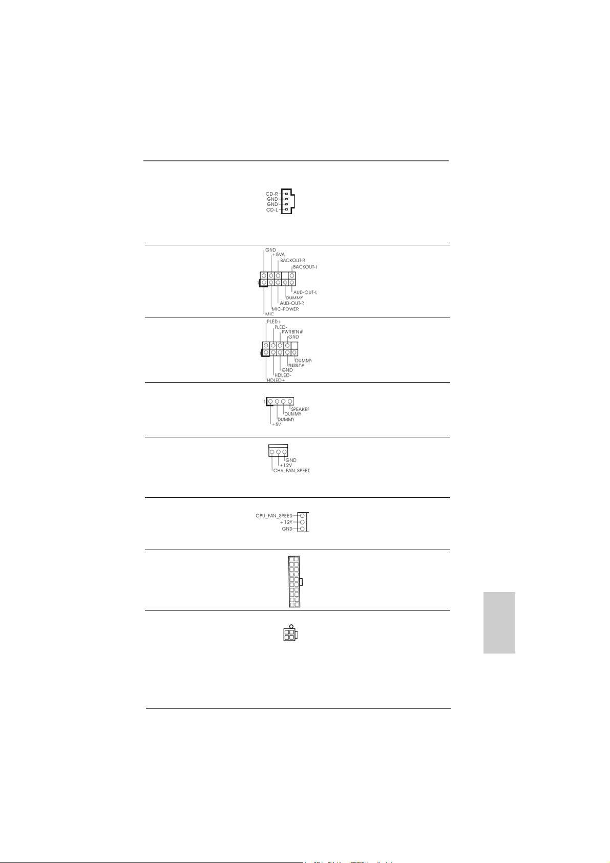
Connecteurs audio internes Ils vous permettent de gérer des
(CD1 br. 4) entrées audio à partir de sources
(CD1: voir p.2 fig. 28) stéréo comme un CD-ROM,
CD1
DVD-ROM, un tuner TV ou une
carte MPEG.
Connecteur audio panneau C’est une interface pour un câble
avant audio en façade qui permet le
(AUDIO1 br. 9) branchement et le contrôle
(voir p.2 fig. 23) commodes de périphériques
audio.
Connecteur pour panneau Ce connecteur offre plusieurs
(PANEL1 br . 9) fonctions système en façade.
(voir p.2 fig. 13)
Connecteur du haut-parleur Veuillez connecter le hautdu châssis parleur de châssis sur ce
(SPEAKER1 br. 4) connecteur.
(voir p.2 fig. 14)
Connecteur pour ventilateur Veuillez connecter le câble du
de châssis ventilateur du châssis sur ce
(CHA_FAN1 br. 3) connecteur en branchant le fil
(voir p.2 fig. 15) noir sur la broche de terre.
Connecteur pour ventilateur Veuillez connecter un câble de
CPU ventilateur d’UC sur ce
(CPU_FAN1 br. 3) connecteur et brancher le fil noir
(voir p.2 fig. 30) sur la broche de terre.
Connecteur d’alimentation ATX Veuillez connecter une unité
(ATXPW R1 br . 20) d’alimentation ATX sur ce
(voir p.2 fig. 29) connecteur.
Connecteur d’alimentation Veuillez noter qu’il est nécessaire
12V ATX de connecter une unité
(ATX12V1 br . 4) d’alimentation électrique avec
(voir p.2 fig. 2) prise ATX 12V sur ce
connecteur afin d’avoir une
alimentation suffisante. Faute de
quoi, il ne sera pas possible de
mettre sous tension.
ASRock 939S56-M Motherboard
5555
55
5555
çaisçais
çaisçais
çais
FranFran
FranFran
Fran
Page 56

Connecteur jeux Connectez un câble jeux sur ce
(GAME1 br. 15) connecteur si le support pour
(voir p.2 fig. 22) port jeux est installée.
2.62.6
Installation des Disques Durs Serial AInstallation des Disques Durs Serial A
2.6
Installation des Disques Durs Serial A
2.62.6
Installation des Disques Durs Serial AInstallation des Disques Durs Serial A
Cette carte mère supporte les disques durs ATA Série (SATA) et les fonctions
RAID (incluant RAID0, RAID1 et JBOB). Cette section vous guidera dans
l’installation de disques durs SATA.
ETAPE 1 : Installez les disques durs SATA dans les baies pour disques de votre
châssis.
ETAPE 2 : Connectez le câble d’alimentation SATA au disque dur SATA.
ETAPE 3 : Connectez l’une des extrémités du câble de données SATA sur le
connecteur SATA de la carte mère.
ETAPE 4 : Connectez l’autre extrémité du câble de données SATA au disque dur
SATA.
1. Si vous planifiez d’utiliser RAID 0, RAID 1, ou les fonctions JBOD sur SATA,
les lecteurs de disques durs SATA doivent fonctionner en mode “RAID”.
2. les modes “RAID” et “non-RAID” sont des options sous le “Mode Opératoire
SATA” dans la configuration du BIOS. Veuillez vous référer à la page 28 pour
plus de détails. Ils ont besoin de pilotes différents durant l’opération
actuelle.
TT
A (SAA (SA
T
A (SA
TT
A (SAA (SA
TT
A)A)
T
A)
TT
A)A)
Français
FrançaisFrançais
FrançaisFrançais
5656
56
5656
2.72.7
Fonction “Hot Plug” (“Connexion à chaud”) pour lesFonction “Hot Plug” (“Connexion à chaud”) pour les
2.7
Fonction “Hot Plug” (“Connexion à chaud”) pour les
2.72.7
Fonction “Hot Plug” (“Connexion à chaud”) pour lesFonction “Hot Plug” (“Connexion à chaud”) pour les
Disques Durs SADisques Durs SA
Disques Durs SA
Disques Durs SADisques Durs SA
La carte mère 939S56-M prend en charge la fonction “Hot Plug” (connexion à
chaud) pour les périphériques SATA.
Qu’est-ce que la fonction “Hot Plug” (connexion à
chaud)?
Si les disques durs SATA ne sont PAS paramétrés pour la configuration RAID, on parle de “Connexion à chaud” pour qualifier
l’opération qui consiste à insérer et retirer les disques durs SATA
pendant que le système est sous tension et en condition de
fonctionnement. Toutefois, veuillez noter que vous ne pouvez pas
effectuer de connexion à chaud si le système d’exploitation a été
installé dans le disque dur SATA.
TT
AA
T
A
TT
AA
ASRock 939S56-M Motherboard
Page 57

ATTENTION !
Bien que cette carte mère prenne en charge la fonction de
Connexion à chaud pour les périphériques SATA, il existe certaines
limitations. Veuillez prendre le soin de lire les instructions sur le CD
d’assistance avant d’utiliser la fonction de Connexion à chaud.
Faute de quoi vous risquez de perdre les données qui se trouvent
dans les disques durs SATA ou d’endommager les disques durs
SATA. Pour les instructions détaillées, veuillez vous reporter à la
documentation qui se trouve dans le CD d’assistance sur le chemin
suivant :
..\ RAID BIOS Setting Utility
2.82.8
FF
aire une disquette du pilote SAaire une disquette du pilote SA
2.8
F
aire une disquette du pilote SA
2.82.8
FF
aire une disquette du pilote SAaire une disquette du pilote SA
fonctionnement SAfonctionnement SA
fonctionnement SA
fonctionnement SAfonctionnement SA
“RAID” Si vous voulez installer Windows 2000, Windows XP, ou Windows XP 64bit SE sur vos lecteurs de disques durs SATA, vous aurez besoin de faire une
disquette du pilote SATA avant de démarrer l’installation du SE.
ETAPE 1 : Insérez le CD de soutien ASRock dans votre lecteur de disque
optique pour démarrer votre système. (N’insérez AUCUNE
disquette dans le lecteur de disquette pour l’instant !)
ETAPE 2 : Pendant le POST au début du démarrage du système, appuyez
sur la touche <F11>, et une fenêtre s’affiche pour la sélection des
périphériques de démarrage. Veuillez sélectionner le CD-ROM
comme périphérique de démarrage.
ETAPE 3 : Lorsque vous voyez s’afficher sur l’écran le message ”Do you
want to generate Serial ATA driver diskette [Y/N]?” (Voulez-vous
générer une disquette de pilotage Série ATA [Y/N]?), appuyez sur
<Y>.
ETAPE 4 : Vous voyez alors s’afficher les messages
Please insert a diskette into the floppy drive.
WARNING! Formatting the floppy diskette will
lose ALL data in it!
Start to format and copy files [Y/N]?
(Insérez une disquette dans le lecteur de disquette.
ATTENTION ! Le formatage de la disquette provoquera
la perte de toutes les données qui s’y trouvent !
Commencer à formater et à copier les fichiers [Y/N].)
Veuillez insérez une disquette dans le lecteur de disquette, et
appuyer sur <Y>.
ETAPE 5: Le système commencera à formater la disquette et copiera les
données des disques durs SATA vers la disquette.
TT
A en ModeA en Mode
T
A en Mode
TT
A en ModeA en Mode
TT
A pour leA pour le
T
A pour le
TT
A pour leA pour le
çaisçais
çaisçais
çais
FranFran
FranFran
Fran
ASRock 939S56-M Motherboard
5757
57
5757
Page 58
Une fois que la disquette de pilotage SATA est prête, vous pouvez
commencer à installer Windows 2000 / Windows XP / Windows XP 64-bit sur
votre système directement sans paramétrer la configuration RAID sur votre
système, ou bien vous pouvez commencer à utiliser l’“Utilitaire de
configuration SiS RAID BIOS” pour paramétrer la configuration RAID 0 /
RAID 1 / JBOD avant d’installer le système d’exploitation. Avant de
commencer à configurer la fonction RAID, vous devez consulter le guide
d’installation sur le CD d’assistance pour connaître la configuration correcte.
Veuillez vous reporter à la documentation qui se trouve sur le CD
d’assistance, “Guide d’installation des disques durs SATA et de configuration
RAID,” qui se trouve dans le dossier sur le chemin suivant :
.. \ RAID BIOS Setting Utility
Vous pouvez également paramétrer la configuration RAID configuration en
utilisant l’“Utilitaire SiS RAID pour Windows” dans un environnement
Windows. Veuillez vous reporter à la documentation sur le CD d’assistance,
“Guide de l’Utilitaire SiS RAID pour Windows,” qui se trouve dans le dossier
sur le chemin suivant :
.. \ RAID Utility for Windows
2.92.9
SASA
TT
2.9
2.92.9
Si vous voulez installer Windows 2000, Windows XP, ou Windows XP 64-bit SE
on vos lecteurs de disques durs SATA fonctionnant en mode non-RAID , vous
n’avez pas besoin de faire une disquette du pilote SATA avant l’installation du SE .
A fonctionnant en mode “non-RAID”A fonctionnant en mode “non-RAID”
SA
T
A fonctionnant en mode “non-RAID”
SASA
TT
A fonctionnant en mode “non-RAID”A fonctionnant en mode “non-RAID”
Windows 98 SE et ME doivent être installés par SATA fonctionnant en
Mode RAID et vous n’avez pas besoin de faire une disquette du pilote SATA
pour ces deux SE avant l’installation du SE.
Français
FrançaisFrançais
FrançaisFrançais
5858
58
5858
ASRock 939S56-M Motherboard
Page 59

3. Informations sur le BIOS3. Informations sur le BIOS
3. Informations sur le BIOS
3. Informations sur le BIOS3. Informations sur le BIOS
La puce Flash Memory sur la carte mère stocke le Setup du BIOS. Lorsque vous
démarrez l’ordinateur, veuillez presser <F2> pendant le POST (Power-On-SelfTest) pour entrer dans le BIOS; sinon, le POST continue ses tests de routine. Si
vous désirez entrer dans le BIOS après le POST, veuillez redémarrer le système
en pressant <Ctl> + <Alt> + <Suppr>, ou en pressant le bouton de reset sur le
boîtier du système.
Vous pouvez également redémarrer en éteignant le système et en le rallumant.
L’utilitaire d’installation du BIOS est conçu pour être convivial. C’est un programme
piloté par menu, qui vous permet de faire défiler par ses divers sous-menus et de
choisir parmi les choix prédéterminés. Pour des informations détaillées sur le
BIOS, veuillez consulter le Guide de l’utilisateur (fichier PDF) dans le CD technique.
4. Informations sur le CD de suppor4. Informations sur le CD de suppor
4. Informations sur le CD de suppor
4. Informations sur le CD de suppor4. Informations sur le CD de suppor
Cette carte mère supporte divers systèmes d’exploitation Microsoft Windows:
98 SE / ME / 2000 / XP. Le CD technique livré avec cette carte mère contient les
pilotes et les utilitaires nécessaires pour améliorer les fonctions de la carte mère.
Pour utiliser le CD technique, insérez-le dans le lecteur de CD-ROM. Le Menu
principal s’affiche automatiquement si “AUTORUN” est activé dans votre
ordinateur.
Si le Menu principal n’apparaît pas automatiquement, localisez dans le CD
technique le fichier ASSETUP.EXE dans le dossier BIN et double-cliquez dessus
pour afficher les menus.
tt
t
tt
çaisçais
çaisçais
çais
FranFran
FranFran
Fran
ASRock 939S56-M Motherboard
5959
59
5959
Page 60

1. Introduzione
Grazie per aver scelto una scheda madre ASRock 939S56-M, una scheda madre
affidabile prodotta secondo i severi criteri di qualità ASRock. Le prestazioni eccellenti
e il design robusto si conformano all’impegno di ASRock nella ricerca della qualità e
della resistenza. Questa Guida Rapida all’Installazione contiene l’introduzione alla
motherboard e la guida passo-passo all’installazione. Informazioni più dettagliate
sulla motherboard si possono trovare nel manuale per l’utente presente nel CD di
supporto.
Le specifiche della scheda madre e il software del BIOS possono
essere aggiornati, pertanto il contenuto di questo manuale può subire
variazioni senza preavviso. Nel caso in cui questo manuale sia
modificato, la versione aggiornata sarà disponibile sul sito di ASRock
senza altro avviso. Potete trovare la lista aggiornata delle memorie e
dei processori supportati anche sul sito di ASRock.
ASRock website http://www.asrock.com
1.11.1
Contenuto della confezioneContenuto della confezione
1.1
Contenuto della confezione
1.11.1
Contenuto della confezioneContenuto della confezione
Scheda madre ASRock 939S56-M
(Micro ATX Form Factor: 9.6-in x 8.8-in, 24.4 cm x 22.4 cm)
Guida di installazione rapida ASRock 939S56-M
CD di supporto ASRock 939S56-M
Un cavo IDE 80-pin Ultra ATA 66/100/133
Un cavo per floppy drive a 1,44 Mb
Un cavo dati Serial ATA (SATA) (Opzionale)
Un cavo alimentatore HDD Serial ATA (SATA) (Opzionale)
Un ASRock 8CH I/O
Italiano
ItalianoItaliano
ItalianoItaliano
6060
60
6060
ASRock 939S56-M Motherboard
Page 61

1.21.2
SpecificheSpecifiche
1.2
Specifiche
1.21.2
SpecificheSpecifiche
Piattaforma: Micro ATX Form Factor: 9.6-in x 8.8-in, 24.4 cm x 22.4 cm
Processore: Presa 939 pin che supporta processore AMD Athlon™ 64 / 64FX
/ 64 X2
Supporto tecnologia AMD “Cool ‘n’ Quiet™” (vedi ATTENZIONE 1)
Chipset: North Bridge: Chipset SiS 756
FSB @ 1GHz (2.0GT/s) / 800MHz
Supporta la tecnologia overclocking “slegata”
(vedi ATTENZIONE 2)
South Bridge: Chipset SiS 965L
Supporta USB 2.0, ATA 133, SATA 1.5Gb/s
Memoria: 4 slot DDR DIMM: DDR1, DDR2, DDR3 e DDR4
PC3200 (DDR400) / PC2700 (DDR333) /
PC2100 (DDR266), Max. 4GB
IDE: IDE1: A TA133 / Ultra DMA Mode 6
IDE2: ATA133 / Ultra DMA Mode 6
Supporta fino a 4 dispositivi IDE
Serial ATA: 2 connettori SATA, supporta velocità di trasferimento dati fino
a 1.5Gb/s
Porta Floppy: Supporta fino a 2 floppy disk drive
Audio: AC’97 Audio a 7.1 canali;
LAN: Velocità: 802.3u (10/100 Ethernet), supporta Wake-On-LAN
Monitoraggio Hardware:
Sensore per la temperatura del processore
Sensore temperatura scheda madre
Chiusura automatica del processore in caso di surriscaldamento
per proteggere la CPU (ASRock U-COP)(vedi ATTENZIONE 3)
Indicatore di velocità per la ventola del processore
Indicatore di velocità per la ventola di raffreddamento
Voltaggio: +12V, +5V, +3.3V, Vcore
Slot PCI: 2 slot con PCI Spec 2.2
Slot PCI EXPRESS:1 slot con PCIE x 1, 1 slot con PCIE x 16; Specifiche PCIE 1.0a
USB 2.0: 8 porte USB 2.0:
4 porte USB 2.0 sono già incluse sul pannello posteriore,
più una guida aggiuntiva che supporta altre 4 porte USB 2.0
(vedi A TTENZIONE 4)
ASRock 8CH I/O: 1 porta PS/2 per mouse, 1 porta PS/2 per tastiera,
1 Porta seriale: COM 1,
1 Porta parallela (supporto ECP/EPP),
4 porte USB 2.0 già integrate,
1 porta RJ-45,
Connettore Audio: ca ssa laterale / cassa posteriore /
ASRock 939S56-M Motherboard
6161
61
6161
ItalianoItaliano
ItalianoItaliano
Italiano
Page 62

Italiano
ItalianoItaliano
ItalianoItaliano
cassa centrale / bassi / ingresso linea /
cassa frontale / microfono
(vedi A TTENZIONE 5)
BIOS: Suppor AMI legal BIOS; Supporta “Plug and Play”;
Compatibile con ACPI 1.1 wake up events;
Supporta SMBIOS 2.3.1;
Stepless control per frequenza del processore
(solo per utenti esperti, vedi ATTENZIONE 6)
Compatibilità SO: Microsoft® Windows® 98 SE / ME / 2000 / XP
ATTENZIONE!
1. Per risparmiare energia si raccomanda vivamente di abilitare la tecnologia
AMD Cool ‘n’ Quiet™ con i sistemi Windows. Fare riferimento a pagina 37
dell’APPENDICE del “Manuale dell’utente”, che si trova nel CD di
supporto, per abilitare la tecnologia AMD Cool ‘n’ Quiet™.
2. Questa scheda madre supporta la tecnologia overclocking “slegata”.
Durante l’overclocking, FSB sarà slegata dai bus PCIE e PCI. In altre
parole, la CPU FSB sarà slegata durante l’overclocking, ma i bus PCIE e
PCI saranno nella modalità fissa in maniera tale che FSB possa operare
in un ambiente di overclocking più stabile.
3. Se il processore si surriscalda, il sistema si chiude automaticamente.
Prima di riavviare il sistema, assicurarsi che la ventolina CPU della
scheda madre funzioni correttamente; scollegare e ricollegare il cavo
d’alimentazione. Per migliorare la dissipazione del calore, ricordare di
applicare l’apposita pasta siliconica tra il processore e il dissipatore
quando si installa il sistema.
4. La Gestione Risorse per USB 2.0 funziona perfettamente con Microsoft
Windows® XP SP1/2000 SP4. Potrebbe dare qualche problema con
Microsoft® Windows® 98/ME.
5. Questa scheda madre supporta l’ingresso stereo e mono per il microfono.
Questa scheda madre supporta le modalità 2 canali, 4 canali, 6 canali e 8
canali per l’uscita audio. Controllare la tavola a pagina 3 per eseguire il
collegamento a ppropri ato.
6. Anche se questa motherboard offre il controllo stepless, non si consiglia
di effettuare l’overclocking. L’uso di frequenze diverse da quelle
raccomandate per il bus CPU possono provocare l’instabilità del sistema
o danneggiare la CPU.
®
6262
62
6262
ASRock 939S56-M Motherboard
Page 63
2. Installazione2. Installazione
2. Installazione
2. Installazione2. Installazione
Precauzioni preinstallazionePrecauzioni preinstallazione
Precauzioni preinstallazione
Precauzioni preinstallazionePrecauzioni preinstallazione
Leggere le seguenti precauzioni prima di installare componenti delle
schede madri o di cambiare le impostazioni delle schede madri.
1. Togliere il cavo dalla presa elettrica prima di toccare le componenti. In
caso contrario la schedamadre, le periferiche, e/o i componenti
possono subire gravi danni.
2. Per evitare che l’elettricità statica danneggi la scheda madre, NON
appoggiare la scheda madre su moquette, tappeti o tessuti simili.
Ricordarsi di indossare un braccialetto antistatico collegato a terra o di
toccare un oggetto posizionato a terra prima di maneggiare le
componenti.
3. Tenere i componenti per i bordi e non toccare i ICs.
4. Ogni volta che si disinstalla un componente, appoggiarlo su un
tappetino antistatico messo a terra o depositarlo nella borsa data in
dotazione con il componente.
5. Nell’usare i giraviti per fissare la scheda madre al telaio non serrare
eccessivamente le viti! Altrimenti si rischia di danneggiare la scheda
madre.
2.1 Installazione del processore2.1 Installazione del processore
2.1 Installazione del processore
2.1 Installazione del processore2.1 Installazione del processore
Step 1. Aprire lo zoccolo sollevando la leva da un angolo di 90°.
Step 2. Posizionare il processore direttamente sullo zoccolo cos da far
combaciare gli angoli segnati con la leva del connettore.
Step 3. Inserire con cautela il processore nello zoccolo finché si adatta
perfettamente.
Il processore ha un solo corretto orientamento. NON forzare il
processore nello zoccolo: i pin potrebbero stortarsi.
Step 4. Quando il processore è posizionato, premere con decisione sullo zoccolo
mentre si abbassa la leva dello zonnettore per fissare il processore.
Quando la leva fa clic sulla linguetta laterale significa che è bloccata.
Step 5. Installare la ventola del processore e l’heatsink. Per una corretta
installazione, per favore fare riferimento ai manuali di istruzione dei
produttori della ventola e dell’heatsink del processore.
ASRock 939S56-M Motherboard
6363
63
6363
ItalianoItaliano
ItalianoItaliano
Italiano
Page 64
2.2 Installazione dei moduli di memoria (DIMM)2.2 Installazione dei moduli di memoria (DIMM)
2.2 Installazione dei moduli di memoria (DIMM)
2.2 Installazione dei moduli di memoria (DIMM)2.2 Installazione dei moduli di memoria (DIMM)
La scheda madre 939S56-M fornisce quattro alloggiamenti DIMM DDR (Double Data
Rate) a 184 pin, e supporta la tecnologia Dual Channel Memory. Per la
configurazione a due canali, è necessario installare sempre coppie identiche
(stessa marca, velocità, dimensioni e tipo di chi p) di DIMM DDR negli alloggiamenti
dello stesso colore. In altre parole, è necessario installare coppie identiche di DIMM
DDR nel canale doppio A (DDR1 e DD R2; alloggiamenti blu; vedere pag. 2 Nr. 5)
oppure coppie identiche di DIMM DDR nel canale doppio B (DDR3 e DDR4;
alloggiamenti neri; vedere pag. 2 Nr. 6), per fare sì che la tecnologia Dual Channel
Memory possa essere attivata. Questa scheda madre consente anche di
installare quattro DIMM DDR per la configurazione a canale doppio.Questa scheda
madre consente anche di installare quattro DIMM DDR per configurazione a canale
duale, si raccoma nda di in stallare DIMM DDR identiche nei quattro alloggiamenti.
Consultare la Tabella configurazione Memoria Canale Duale di seguito.
Configurazioni Dual Channel Memory
DDR1 DDR2 DDR3 DDR4
(alloggia mento blu) (alloggia mento blu) (alloggia mento nero) (alloggia mento nero)
(1) Popolato Popolato - (2) - - Popolato Popolato
(3) Popolato Popolato Popolato Popolato
* Per la configurazione (3), installare DDR DIMM identici nei quattro slot.
* Si consiglia di installare in primo luogo la DDR1 e la DDR2, quindi di
installare la DDR3 e la DDR4.
Italiano
ItalianoItaliano
ItalianoItaliano
6464
64
6464
1. Se si desidera installare due moduli di memoria differenti, si consiglia,
per una maggiore compatibilità ed affidabilità, di installarli negli slot di
colore differente, in altre parole, di installarli sia nella DDR1 che nella
DDR3.
2. Se negli alloggiamenti DIMM di questa scheda madre è installato un
solo modulo di memoria, oppure sono installati tre moduli di memoria,
è impossibile attivare la tecnologia Dual Channel Memory.
3. Se una coppia di moduli di memoria NON è installata nello stesso
“canale doppio”, ad esempio se si installa una coppia di moduli di
memoria su DDR1 e DD3, è impossibile attivare la tecnologia
Dual Channel Memory.
ASRock 939S56-M Motherboard
Page 65

Installare una DIMMInstallare una DIMM
Installare una DIMM
Installare una DIMMInstallare una DIMM
Scollegare l’alimentazione elettrica prima di aggiungere o rimuovere i
DIMM o altri componenti del sistema.
Step 1. Sbloccare lo slot DIMM premendo i fermi che lo trattengono verso
l’esterno.
Step 2. Allineare una DIMM sullo slot così che il pettine della DIMM combaci con
la sua sede sullo slot.
La DIMM può essere montata correttamente soltanto con un
orientamento. Se si dovesse installare a forza la DIMM nello slot con
un orientamento errato, si causerebbero danni permanenti alla scheda
madre e alla DIMM stessa.
Step 3. Inserire saldamente la DIMM nello slot fino a far scattare completamente
in posizione i fermagli di ritegno alle due estremità e fino ad installare
correttamente la DIMM nella sua sede.
ASRock 939S56-M Motherboard
6565
65
6565
ItalianoItaliano
ItalianoItaliano
Italiano
Page 66

2.3 Slot di espansione (PCI e slot PCI Express)2.3 Slot di espansione (PCI e slot PCI Express)
2.3 Slot di espansione (PCI e slot PCI Express)
2.3 Slot di espansione (PCI e slot PCI Express)2.3 Slot di espansione (PCI e slot PCI Express)
La motherboard 939S56-M dispone di 2 slot PCI e 2 slot PCI Express.
Slot PCI: Sono utilizzati per installare schede di espansione con Interfaccia PCI
a 32-bit.
Slot PCI Express: PCIE1 (slot PCIE x16) usato per schede PCI Express con
schede grafiche di larghezza x16. PCIE2 (slot PCIE x1) usato
per schede PCI Express, quali scheda Gigabit LAN, SATA II,
ecc.
Installare una scheda di espansioneInstallare una scheda di espansione
Installare una scheda di espansione
Installare una scheda di espansioneInstallare una scheda di espansione
Step 1. Prima d’installare la scheda di espansione, assicurarsi che l’alimentazione
sia stata esclusa oppure che il cavo di alimentazione sia scollegato. Prima
di iniziare l’installazione, si prega di leggere la documentazione della scheda
di espansione e di effettuare le necessarie impostazioni del hardware.
Step 2. Rimuovere i ganci sullo slot che si intende utilizzare. Tenere a portata di mano
le viti.
Step 3. Allineare il connettore della scheda con lo slot e premere con decisione
finché la scheda è completamente inserita nello slot.
Step 4. Agganciare la scheda allo chassis con le viti.
Italiano
ItalianoItaliano
ItalianoItaliano
6666
66
6666
ASRock 939S56-M Motherboard
Page 67

2.4 Setup dei Jumpers2.4 Setup dei Jumpers
2.4 Setup dei Jumpers
2.4 Setup dei Jumpers2.4 Setup dei Jumpers
L’illustrazione mostra come sono settati i jumper.
Quando il ponticello è posizionato sui pin, il jumper
è “CORTOCIRCUITATO”. Se sui pin non ci sono
ponticelli, il jumper è “APERTO”. L’illustrazione
mostra un jumper a 3 pin in cui il pin1 e il pin2 sono
“CORTOCIRCUITATI” quando il ponticello è
posizionato su questi pin.
Jumper Settaggio del Jumper
PS2_USB_PW1 Cortocircuitare pin2, pin3 per
(vedi p.2 item 1) settare a +5VSB (standby) e
Nota: Per selezionare +5VSB, si richiedono almeno 2 Ampere e il consumo di
corrente in standby sarà maggiore.
Jumper JR1JL1
(vedi p.2 item 24)
Nota: Se i jumper JR1 e JL1 sono in corto, possono funzionare i connettori audio
del pannello frontale e del pannello posteriore.
Resettare la CMOS
(CLRCMOS2)
(vedi p.2 item 18)
jumper a 2 pin
CORTOCIRCUIT ATO APERTO
abilitare PS/2 o USB wake up
events.
Nota: CLRCMOS2 permette di cancellare i dati presenti nel CMOS. I dati del CMOS
comprendono le informazioni di configurazione quali la password di sistema,
data, ora, e i parametri di configurazione del sistema. Per cancellare e
ripristinare i parametri del sistema, spegnere il computer e togliere il cavo di
alimentazione dalla presa di corrente. Dopo aver lasciato trascorrere 15
secondi, utilizzare un terminatore di cap per cortocircuitare il jumper Clear
CMOS per 5 secondi. Dopo aver cortocircuitato il jumper Clear CMOS jumper,
togliere il terminatore jumper. Non cancellare la CMOS subito dopo aver
aggiornato il BIOS. Se è necessario cancellare la CMOS una volta completato
l’aggiornamento del BIOS, è necessario riavviare prima il sistema, e poi
spegnerlo prima di procedere alla cancellazione della CMOS.
ASRock 939S56-M Motherboard
6767
67
6767
ItalianoItaliano
ItalianoItaliano
Italiano
Page 68

2.5 Connettori2.5 Connettori
2.5 Connettori
2.5 Connettori2.5 Connettori
I connettori NON sono jumpers. NON COLLOCARE i ponticelli sui
connettori. Installando dei cappucci a ponticello sui connettori si
causeranno danni permanenti alla scheda madre!
Connettori Descrizione dei connettori
Connettore del
Floppy disk
(33-pin FLOPPY1)
(vedi p.2 item 21)
Lato del Pin1 con la striscia rossa
Nota: Assicurarsi che il lato del cavo con la striscia rossa sia inserito nel lato Pin1
del connettore.
Connettore IDE primario (blu) Connettore IDE secondario (nero)
(39-pin IDE1, vedi p.2 item 8) (39-pin IDE2, vedi p.2 item 7)
Connettore blu Connettore nero
alla scheda madre all’hard disk drive
Cavo ATA 66/100/133 a 80 pin
Nota: Se utilizzate un solo dispositivo IDE su questa scheda madre, imposta tale
dispositivo come “Master”. Fate riferimento alle istruzioni del produttore del
dispositivo IDE per maggiori dettagli. Inoltre, per ottimizzare compatibilità e
prestazioni, connettete l’hard disk al connettore primario IDE (IDE1, blu) e il
CD-ROM al connettore IDE secondario (IDE2, nero).
Italiano
ItalianoItaliano
ItalianoItaliano
6868
68
6868
Connettori Serial ATA Questi due connettori Serial
(SAT A1: vedi p.2 item 1 1) ATA (SATA) supportano cavi
(SAT A2: vedi p.2 item 12) dati SATA per dispositivi di
SAT A1
immagazzinamento interni.
SAT A2
ATA (SATA) supportano cavi
SATA per dispositivi di memoria
interni. L’interfaccia SATA
attuale permette velocità di
trasferimento dati fino a 1.5 Gb/s.
ASRock 939S56-M Motherboard
Page 69

Cavi dati Serial ATA (SATA) Entrambe le estremità del cavo
dati SATA possono collegarsi
all’hard disk SATA o al
connettore SATA sulla scheda
madre.
Cavo d’alimentazione Collegare l’estremità nera de
Serial ATA (SATA) cavo di alimentazione SATA al
(Opzionale) connettore di alimentazione del
Connettere all’ailmentazione
dei dischi SAT A
Connettere al gruppo
di alimentazione
drive. Poi connettete l’estremità
bianca del cavo di
alimentazione SATA al
connettore power
dell’alimentatore.
Collettore USB 2.0 Il dispositivo ASRock 8CH I/O
(9-pin USB67) mette a vostra disposizione 4
(vedi p.2 No. 16) porte USB 2.0 di default sul
pannello posteriore. Se le porte
USB posteriori non sono
sufficienti, è disponibile questo
collettore USB 2.0 (USB67)
che può supportare altre 2
porte USB 2.0.
Collettore USB 2.0 Il dispositivo ASRock 8CH I/O
(9-pin USB_H4_5) mette a vostra disposizione 4
(vedi p.2 No. 17) porte USB 2.0 di default sul
pannello posteriore. Se le porte
USB posteriori non sono
sufficienti, è disponibile questo
collettore USB 2.0 (USB_H45)
che può supportare altre 2
porte USB 2.0.
Collettore modulo Questo collettore supporta
infrarossi una wireless opzionale che
(5-pin IR1) trasmette e riceve moduli
(vedi p.2 item 19) infrarossi.
ASRock 939S56-M Motherboard
6969
69
6969
ItalianoItaliano
ItalianoItaliano
Italiano
Page 70
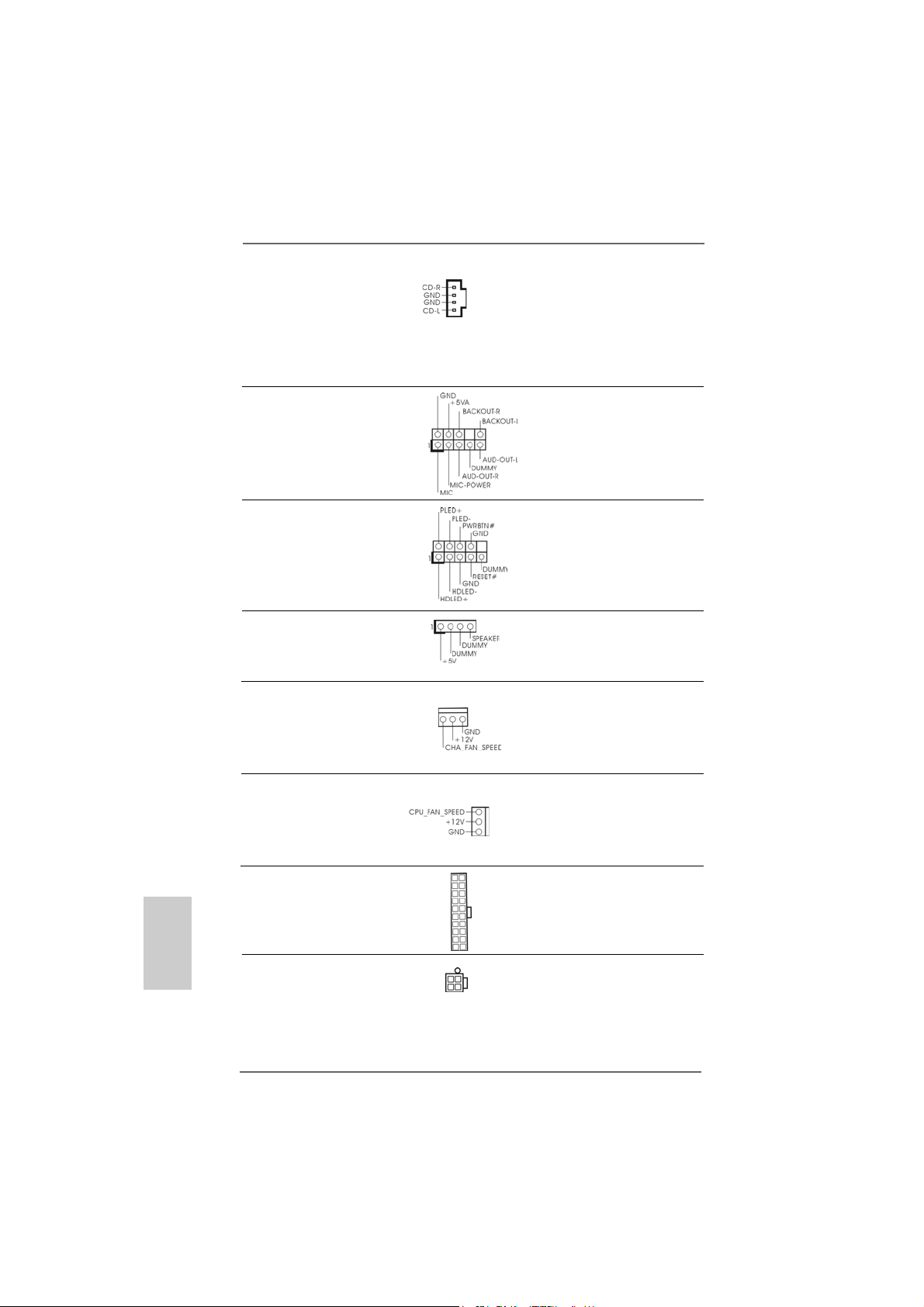
Connettori audio interni Permettono di ricevere input
(4-pin CD1) stereo audio da fonti di
(CD1: vedi p.2 item 28) suono come CD-ROM, DVD -
CD1
ROM,TV tuner, o schede
MPEG.
Connettore audio sul È un’interfaccia per il cavo del
pannello frontale pannello audio. Che consente
(9-pin AUDIO1) connessione facile e controllo
(vedi p.2 item 23) dei dispositivi audio.
Connettore del panello Questo connettore accoglie
frontale diverse funzioni del pannello
(9-pin PANEL1) frontale.
(vedi p.2 item 13)
Collettore casse telaio Collegare le casse del telaio a
(4-pin SPEAKER1) questo collettore.
(vedi p.2 item 14)
Connettore ventolina telaio Collegare il cavo della ventolina
(3-pin CHA_FAN1) telaio a questo connettore e far
(vedi p.2 item 15) combaciare il filo nero al pin
terra.
Italiano
ItalianoItaliano
ItalianoItaliano
7070
70
7070
Connettore ventolina CPU Collegare il cavo della ventolina
(3-pin CPU_FAN1) CPU a questo connettore e far
(vedi p.2 item 30) combaciare il filo nero al pin
terra.
Collettore alimentazione ATX Collegare la sorgente
(20-pin ATXPW R1) d’alimentazione ATX a questo
(vedi p.2 item 29) collettore.
Connettore ATX 12V È necessario collegare una
(4-pin ATX12V1) alimentazione con spinotto da
(vedi p.2 item 2) 12V ATX a questo connettore
in modo che possa fornire
energia sufficiente. In caso
contrario l’unità non si avvia.
ASRock 939S56-M Motherboard
Page 71
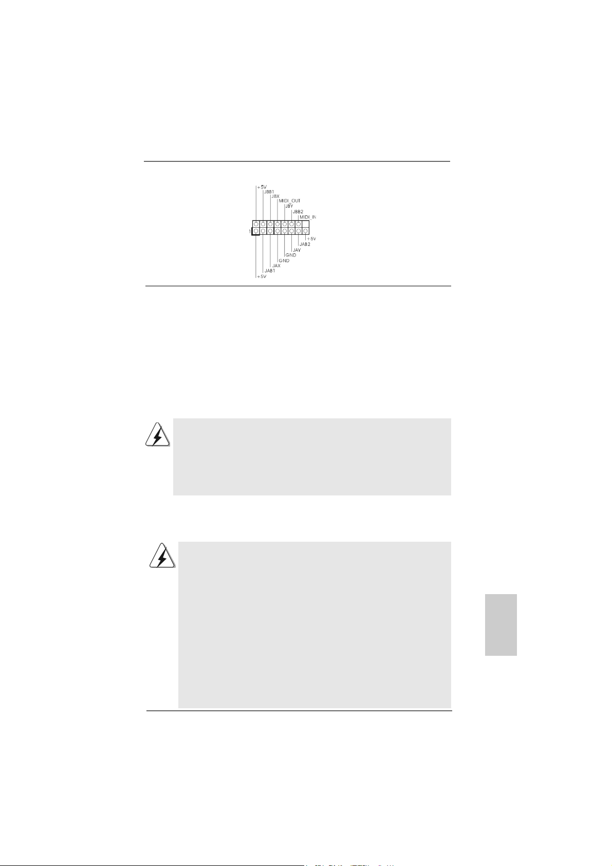
Connettore porta giochi Connettere un cavo Game a
(15-pin GAME1) questo connettore solo se la
(vedi p.2 item 22) porta giochi è installata.
2.62.6
Installazione di Hard Disk AInstallazione di Hard Disk A
2.6
Installazione di Hard Disk A
2.62.6
Installazione di Hard Disk AInstallazione di Hard Disk A
Questa scheda madre supporta dischi rigidi Serial ATA (SATA) e funzioni RAID (tra
cui RAID0, RAID1 e JBOB). Questa sezione offre una guida per installare i dischi
rigidi SATA.
1° PASSO: Installare gli Hard Disk SATA negli spazi per le unità disco del telaio.
2° PASSO: Collegare il cavo d’alimentazione SATA al disco rigido SATA.
3° PASSO: Collegare un’estremità del cavo dati SATA al connettore SATA della
motherboard.
4° PASSO: Collegare l’altra estremità del cavo dati SATA all’hard disk SATA.
1. Per utilizzare le funzioni RAID 0, RAID 1 o JBOD su SATA, gli hard disk SATA
devono operare in modalità “RAID”.
2. Le modalità “RAID” e “non RAID” possono essere selezionate nella
configurazione del BIOS sotto “SATA Operation Mode” (Modalità operativa
SATA). Per ulteriori particolari vedi pag. 28 Le due modalità richiedono driver
diversi in fase d’uso effettivo.
TT
A Seriali (SAA Seriali (SA
T
A Seriali (SA
TT
A Seriali (SAA Seriali (SA
TT
A)A)
T
A)
TT
A)A)
2.72.7
FF
2.7
2.72.7
La scheda madre 939S56-M supporta la funzione Hot Plug per dispositivi SATA.
unzione Hot Plug per SAunzione Hot Plug per SA
F
unzione Hot Plug per SA
FF
unzione Hot Plug per SAunzione Hot Plug per SA
Che cos’è la funzione Hot Plug?
Se gli HD SATA NON sono impostati per la configurazione RAID,
“Hot Plug” indica l’azione di inserimento e rimozione dell’HD SATA
mentre il sistema è ancora accesso e funzionante. Tuttavia, la
funzione Hot Plug non è disponibile se il sistema operativo è stato
installato sull’HD SATA.
ATTENZIONE!
Anche se questa scheda madre supporta la funzione Hot Plug per i
dispositivi SATA, ci sono ancora dei limiti. Leggere con attenzione le
istruzioni contenute nel CD prima di utilizzare la funzione Hot Plug.
Si rischia altrimenti di perdere i dati dell’HD SATA o di danneggiare
l’HD SATA. Per maggiori informazioni, consultare la documentazione
nel CD nel percorso:
..\ RAID BIOS Setting Utility
ASRock 939S56-M Motherboard
TT
A HDDA HDD
T
A HDD
TT
A HDDA HDD
7171
71
7171
ItalianoItaliano
ItalianoItaliano
Italiano
Page 72

2.82.8
Creazione di un dischetto contenente il driver SACreazione di un dischetto contenente il driver SA
2.8
Creazione di un dischetto contenente il driver SA
2.82.8
Creazione di un dischetto contenente il driver SACreazione di un dischetto contenente il driver SA
per il funzionamento dell’hard disk SAper il funzionamento dell’hard disk SA
per il funzionamento dell’hard disk SA
per il funzionamento dell’hard disk SAper il funzionamento dell’hard disk SA
“RAID”.“RAID”.
“RAID”.
“RAID”.“RAID”.
Se si desidera installare Windows 2000, Windows XP o Windows XP 64 bit su un
hard disk SATA, è necessario creare un dischetto driver SATA prima di procedere
con l’installazione del sistema operativo.
1° PASSO: Inserire il CD di supporto ASRock nel lettore ottico prima di
accendere il sistema. (NON inserire nessun dischetto floppy
nel drive in questo momento!)
2° PASSO: Durante la fase di POST, all’inzio del boot-up del sistema,
premere il tasto <F11>. Apparirà una finestra per la selezione
dei dispositivi boot. Scegliere CD-ROM come dispositivo di
boot. Durante la fase di POST, all’inzio del boot-up del
sistema, premere il tasto <F11>. Apparirà una finestra per la
selezione dei dispositivi boot. Scegliere CD-ROM come
dispositivo di boot.
3° PASSO: Quando sullo schermo compare il messaggio: ”Do you want
to generate Serial ATA driver diskette [Y/N]?” (Vuoi creare un
dischetto di driver Serial ATA [Y/N]?), premere <Y>.
4° PASSO: Di seguito ci sarà questo messaggio:
Please insert a diskette into the floppy drive.
WARNING! Formatting the floppy diskette will
lose ALL data in it!
Start to format and copy files [Y/N]?
(Inserire un dischetto nel floppy drive.
ATTENZIONE! La formattazione del dischetto floppy
comporterà la perdita di TUTTI i dati in esso contenuti!
Iniziare a formattare e copiare i file [Y/N]?)
Inserire un dischetto floppy nel floppy drive e premere <Y>.
5° PASSO: Il sistema inizierà a formattare il floppy-disk e a copiare i
driver SATA su questo.
TT
A in modalitàA in modalità
T
A in modalità
TT
A in modalitàA in modalità
TT
AA
T
A
TT
AA
Italiano
ItalianoItaliano
ItalianoItaliano
7272
72
7272
Una volta pronto il dischetto driver per il SATA, si può iniziare l’installazione di
Windows 2000 / Windows XP / Windows XP 64-bit direttamente senza dover impostare
a configurazione RAID del sistema, o si può iniziare a utilizzare il “SiS RAID BIOS
Setting Utility” per impostare RAID 0 / RAID 1 / JBOD prima di installare il sistema
operativo. Prima di iniziare a configurare la funzione RAID, è necessario verificare la
configurazione corretta nella guida all’installazione contenuta nel CD . Consultare la
documentazione nel CD, “Guida all’installazione degli hard disk SA TA e alla
configurazione RAID,” che si trova nella cartella:
.. \ RAID BIOS Setting Utility
ASRock 939S56-M Motherboard
Page 73

È anche possibile configurare il RAID utilizzando la “Utility SiS RAID per Windows” in
ambiente Windows. Consultare la documentazione nel CD, “Guida alla utility SiS RAID
per Windows,” che si trova nella cartella :
.. \ RAID Utility for Windows
2.92.9
SASA
TT
2.9
2.92.9
Se si desidera installare Windows 2000, Windows XP o Windows XP 64 bit su un
hard disk SATA operante in modalità non RAID, non è necessario creare un
dischetto driver SATA prima dell’installazione del sistema operativo.
3. Informazioni sul BIOS3. Informazioni sul BIOS
3. Informazioni sul BIOS
3. Informazioni sul BIOS3. Informazioni sul BIOS
La Flash Memory sulla scheda madre contiene le Setup Utility. Quando si avvia il
computer, premi <F2> durante il Power-On-Self-Test (POST) della Setup utility del
BIOS; altrimenti, POST continua con i suoi test di routine. Per entrare il BIOS Setup
dopo il POST, riavvia il sistema premendo <Ctl> + <Alt> + <Delete>, o premi il tasto
di reset sullo chassis del sistema.
El BIOS Setup Utility es diseñádo “user-friendly”. Es un programa guido al menu,
es decir, puede enrollarse a sus varios su-menues y elegir las opciones
predeterminadas. Per informazioni più dettagliate circa il Setup del BIOS, fare
riferimento al Manuale dell’Utente (PDF file) contenuto nel cd di supporto.
A operante in modalità “non-RAID”A operante in modalità “non-RAID”
SA
T
A operante in modalità “non-RAID”
SASA
TT
A operante in modalità “non-RAID”A operante in modalità “non-RAID”
I sistemi operativi Windows 98 SE e Windows ME devono essere installati con
SATA operante in modalità RAID, senza che sia necessario creare un dischetto
driver SATA prima dell’installazione del sistema operativo.
4. Software di suppor4. Software di suppor
4. Software di suppor
4. Software di suppor4. Software di suppor
su CDsu CD
su CD
su CDsu CD
Questa scheda madre supporta vari sistemi operativi Microsoft Windows: 98 SE /
ME / 2000 / XP. Il CD di supporto a corredo della scheda madre contiene i driver e
utilità necessari a potenziare le caratteristiche della scheda.
Inserire il CD di supporto nel lettore CD-ROM. Se la funzione “AUTORUN” è attivata
nel computer, apparirà automaticamente il Menù principale.
Se il Menù principale non appare automaticamente, posizionarsi sul file ASSETUP.
EXE nel CESTINO del CD di supporto e cliccare due volte per visualizzare i menù.
ASRock 939S56-M Motherboard
to e informazionito e informazioni
to e informazioni
to e informazionito e informazioni
7373
73
7373
ItalianoItaliano
ItalianoItaliano
Italiano
Page 74

1. Introducción1. Introducción
1. Introducción
1. Introducción1. Introducción
Gracias por su compra de ASRock 939S56-M placa madre, una placa de confianza
producida bajo el control de calidad estricto y persistente. La placa madre provee
realización excelente con un diseño robusto conforme al compromiso de calidad y
resistencia de ASRock.
Esta Guía rápida de instalación contiene una introducción a la placa base y una guía
de instalación paso a paso. Puede encontrar una información más detallada sobre la
placa base en el manual de usuario incluido en el CD de soporte.
Porque las especificaciones de la placa madre y el software de BIOS
podrían ser actualizados, el contenido de este manual puede ser cambiado
sin aviso. En caso de cualquier modificación de este manual, la versión
actualizada estará disponible en el website de ASRock sin previo aviso.
Puede encontrar también las listas más recientes de soporte de memoria y
CPU en el sitio web ASRock.
Website de ASRock http://www.asrock.com
1.11.1
Contenido de la cajaContenido de la caja
1.1
Contenido de la caja
1.11.1
Contenido de la cajaContenido de la caja
Placa base ASRock 939S56-M
(Factor forma Micro ATX: 24,4 cm x 22,4 cm, 9,6” x 8,8”)
Guía de instalación rápida de ASRock 939S56-M
CD de soporte de ASRock 939S56-M
Una cinta de datos IDE de conducción 80 Ultra ATA 66/100/133
Una cinta de datos para una unidad de disco de 3,5”
Un Cable de Datos Serial ATA (SATA) (Opcional)
Un cable serie ATA (SATA) de alimentación de disco duro (Opcional)
Una protección ASRock 8CH I/O
Español
EspañolEspañol
EspañolEspañol
7474
74
7474
ASRock 939S56-M Motherboard
Page 75
1.21.2
EspecificaciónEspecificación
1.2
Especificación
1.21.2
EspecificaciónEspecificación
Plataforma: Factor forma Micro ATX: 24,4 cm x 22,4 cm, 9,6” x 8,8”
Procesador: Socket de 939 agujas con soporte para procesador AMD
Athlon 64 / 64FX / 64 X2; Compatible con la tecnología Cool
‘n’ Quiet de AMD (vea ATENCIÓN 1)
Chipset: North Bridge: Chipset SiS 756
FSB @ 1GHz (2.0 GT/s) / 800MHz
Admite tecnología de aumento de velocidad liberada
(vea ATENCIÓN 2)
South Bridge: Chipset SiS 965L
Soporta USB 2.0, ATA 133, SATA 1.5Gb/s
Memoria: 4 DDR DIMM slots: DDR1, DDR2, DDR3 y DDR4
PC3200 (DDR400) / PC2700 (DDR333) /
PC2100 (DDR266), Max. 4GB
IDE: IDE1: ATA 133 / Ultra DMA Mode 6
IDE2: ATA 133 / Ultra DMA Mode 6
Admite hasta 4 dispositivos IDE
ATA serie: 2 conexiones SATA, admiten una velocidad de transferencia
de datos de hasta 1,5Gb/s
Admite hasta 2 unidades de disco
Audio: 7.1 canales de Audio AC97
LAN: Velocidad: 802.3u (10/100 Ethernet), soporta Wake-On-LAN
Monitor Hardware:Sensibilidad a la temperatura del procesador,
Sensibilidad a la temperatura de la placa madre,
Apago automático en caso de temperature sobre-elevada del
procesador para proteger el procesador
(ASRock U-COP)(vea ATENCIÓN 3),
Taquímetros de los ventiladores del procesador y del chasis,
Monitor de Voltaje: +12V, +5V, +3.3V, Vcore
Ranura PCI: 2 ranuras con PCI especificación 2.2
Ranura PCI Express: 1 ranura con PCIE x 1, 1 ranura con PCIE x 16;
Especificación PCIE 1.0a
USB 2.0: 8 puertos USB 2.0:
incluye 4 puertos USB 2.0 predeterminados en la parte
trasera, más un terminal que admite 4 puertos USB 2.0
adicionales (vea ATENCIÓN 4)
ASRock 8CH I/O: 1 puerto de ratón PS/2, 1 puerto de teclado PS/2,
1 puerto serial: COM 1,
1 puerto paralelo (soporta ECP/EPP),
4 puertos USB 2.0 predeterminados,
1 puerto RJ-45,
EspañolEspañol
EspañolEspañol
Español
ASRock 939S56-M Motherboard
7575
75
7575
Page 76

Español
EspañolEspañol
EspañolEspañol
Conexión de audio: Altavoz lateral / Altavoz trasero /
Central/Bajos / Entrada de línea /
Altavoz frontal / Micrófono
(ver ATENCIÓN 5)
BIOS: AMI legal BIOS; Soporta “Plug and Play”;
ACPI 1.1 compliance wake up events; Soporta SMBIOS 2.3.1;
Stepless control de frecuencia de CPU (solamente para
referencia a usuarios avanzados, vea ATENCIÓN 6)
OS: En conformidad con Microsoft® Windows® 98 SE / ME / 2000 /
XP
ATENCIÓN!
1. Para ahorrar electricidad, se recomienda activar la tecnología Cool ‘n’
Quiet™ de AMD en el sistema Windows. Consulte el APÉNDICE en la
página 37 del “User Manual” (Manual del usuario) del CD de soporte para
activar la tecnología Cool ‘n’ Quiet™ de AMD.
2. Esta placa base admite la tecnología de aumento de velocidad liberada.
FSB se liberará de los buses PCIE y PCI durante la fase de aumento de
velocidad del reloj. En otras pala bra s, FSB del proce sador quedará libera do
durante la fase de aumento de velocidad del reloj, pero los buses PCIE y
PCI permanecerán en el modo fi jo de f orma que FSB pueda funcionar bajo
un entorno de aumento de velocidad de reloj más estable.
3. Cuando la temperatura de CPU está sobre-elevada, el sistema va a
apagarse automaticamente. Antes de reanudar el sistema, compruebe si
el ventilador de la CPU de la placa base funciona apropiadamente y
desconecte el cable de alimentación, a continuación, vuelva a conectarlo.
Para mejorar la disipación de calor, acuérdese de aplicar thermal grease
entre el procesador y el disipador de calor cuando usted instala el sistema
de PC.
4. Power Management para USB 2.0 funciona bien ba jo M icrosoft
XP SP1/2000 SP4. Es posible que no funcione propiamente bajo Microsoft
Windows® 98/ME.
5. Para la entrada de micrófono, esta placa madre ofrece soporte para
modos estéreo y mono. Para salida de audio, este placa madre ofrece
soporte para modos de 2 canales, 4 canales, 6 canales y 8 canales.
Consulte la tabla en la página 3 para una conexión correcta.
6. Aunque esta placa base ofrece un control complete, no es recomendable
forzar la velocidad. Las frecuencias de bus de la CPU distintas a las
recomendadas pueden causar ine stabilidad en el sistema o dañar la CPU.
®
Windows
®
®
7676
76
7676
ASRock 939S56-M Motherboard
Page 77

2.2.
InstalaciónInstalación
2.
Instalación
2.2.
InstalaciónInstalación
Precaución de Pre-instalaciónPrecaución de Pre-instalación
Precaución de Pre-instalación
Precaución de Pre-instalaciónPrecaución de Pre-instalación
Tenga en cuenta las precauciones siguientes antes de instalar
los componentes de la placa base o cambiar cualquier
configuración de la placa base.
1. Desconecte el cable de electricidad antes de tocar cualquier
componente.
2. Para prevenir daño del componente de la placa madre por electricidad
estástica, NUNCA ponga su placa madre directamente sobre la
alfombra y otros por el estilo. Póngase la pulsera anti-estástica o
toquelo a cualquier objecto de tierra, por ejémplo como el cabinete de
su computador, para liberar cualquiera carga estástica.
3. Tome componentes por la margen y no toque los ICs.
4. Ponga cualquier componente deslocalizado sobre la bolsa anti-estástica
que viene con la placa madre.
5. Al colocar los tornillos en sus agujeros para fijar la placa madre en el
chasis, no los apriete demasiado. Eso podría dañar la placa madre.
2.1 Instalación de Procesador2.1 Instalación de Procesador
2.1 Instalación de Procesador
2.1 Instalación de Procesador2.1 Instalación de Procesador
Paso 1. Desbloquee el zócalo arrastrando la palanca hacia afuera y hacia arriba
en un ángulo de 90o.
Paso 2. Coloque el CPU sobre el zócalo tal como la esquina marcada de CPU
corresponde la esquina de zócalo cerca del terminal de la palanca, mientras
tanto asegúrese que el CPU está en paralelo con el zócalo.
Paso 3. Coloque cuidosamente el CPU en el zócalo.
El CPU se encaja al zócalo a una sola orientación. No esfuerce el CPU en
el zócalo para prevenir encorvados de los pins del CPU. Si no puede
encajar el CPU, examine su orientación o examine si los pins están ya
encorvados.
Paso 4. Encierre el zócalo bajando la palanca.
Paso 5. Instale el disipador de calor con ventilador del CPU ( consulte la
documentación del disipador de calor).
ASRock 939S56-M Motherboard
7777
77
7777
EspañolEspañol
EspañolEspañol
Español
Page 78

2.2 Instalación de Memoria2.2 Instalación de Memoria
2.2 Instalación de Memoria
2.2 Instalación de Memoria2.2 Instalación de Memoria
La placa 939S56-M ofrece cuatro ranuras DIMM DDR de 184 pines, y soporta
Tecnología de Memoria de Doble Canal. Para la configuración de doble canal,
necesitará instalar siempre pares DIMM DDR idénticos (de la misma marca,
velocidad, tamaño y tipo) en las ranuras del mismo color. En otras palabras, tendrá
que instalar pares DDR DIMM de Doble Canal A (DDR1 y DDR2; Ranura s Azules;
consulte la p. 2 N. 5) o pares idénticos DDR DIMM en el Doble Canal B (DDR3 y
DDR4; ranuras Negras; consulte p.2 N.6), de modo que pueda activarse la
Tecnología de Memoria de Doble Canal. Esta placa base también le permite instalar
cuatro DIMMs DDR para configuración de doble canal. Esta placa base también
permite instalar cuatro módulos DDR DIMM para configuraciones de doble canal,
siempre que instale módulos DDR DIMM idénticos en las cuatro ranuras. Puede
consultar la tabla de configuración de memoria de doble canal que se muestra a
continuación.
Configuraciones de Memoria de Doble Canal
DDR1 DDR2 DDR3 DDR4
(Ranura Azul)(Ranura Azul) (Ranura Negra) (Ranura Negra)
(1) Populada Populada - (2) - - Populada Populada
(3) Populada Populada Populada Populada
* Para la configuración (3), instale DIMM DDR idénticas en las cuatro
ranuras.
* Se recomienda instalar primero en DDR1 y DDR2. A continuación se
pueden instalar en DD R3 y DDR4.
Español
EspañolEspañol
EspañolEspañol
7878
78
7878
1. Si desea instalar dos módulos de memoria distintos, para obtener
compatibilidad y fiabilidad óptimas se recomienda instalarlos en
ranuras de diferente color. En otras palabras, instalarlos en DDR1 y
DDR3.
2. Si se instalan sólo un módulo de memoria o tres módulos de memoria
en las ranuras DIMM DDR de esta placa base, no será posible activar
la Tecnología de Memoria de Doble Canal.
3. Si un par de módulos de memoria NO está instalado en el mismo
“Canal Doble”, por ejemplo, al instalar un par de módulos de
memoria en DDR1 y DDR3, no será posible activar la Tecnología
de Memoria de Doble Canal.
ASRock 939S56-M Motherboard
Page 79

Instalación de una DIMMInstalación de una DIMM
Instalación de una DIMM
Instalación de una DIMMInstalación de una DIMM
Asegúrese de desconectar la fuente de alimentación antes de añadir o
retirar módulos DIMM o componentes del sistema.
Paso 1. Empuje los clips blancos de retención por el extremo de cada lado de la
ranura de memoria.
Paso 2. Encaje la muesca del DIMM hacia la cumbrera de la ranura.
DIMM ajusta solamente en una dirección. Si fuerza la DIMM en la
ranura con una orientación incorrecta, provocará daños permanentes
en la placa base y en la DIMM.
Paso 3. Inserte la DIMM con firmeza dentro de la ranura hasta que los clips de
sujeción de ambos lados queden completamente introducidos en su sitio y
la DIMM se haya asentado apropiadamente.
ASRock 939S56-M Motherboard
7979
79
7979
EspañolEspañol
EspañolEspañol
Español
Page 80

2.3 Ranuras de Expansión (Ranuras PCI y PCI Express )2.3 Ranuras de Expansión (Ranuras PCI y PCI Express )
2.3 Ranuras de Expansión (Ranuras PCI y PCI Express )
2.3 Ranuras de Expansión (Ranuras PCI y PCI Express )2.3 Ranuras de Expansión (Ranuras PCI y PCI Express )
En la placa base 939S56-M hay 2 ranuras PCI y 2 PCI Express.
Ranura PCI: Para instalar tarjetas de expansión que tienen 32-bit Interface PCI.
Ranura PCI Express: PCIE1 (ranura PCIE x16) se utiliza para tarjetas PCI Ex
press con tarjetas gráficas con una anchura de 16
carriles. PCIE2 (1 ranura PCIE) es utiliza para tarjetas PCI
Express, como por ejemplo, para tarjetas Gigabit LAN,
SATA II, etc.
Español
EspañolEspañol
EspañolEspañol
Instalación de TInstalación de T
Instalación de T
Instalación de TInstalación de T
Paso 1. Antes de instalar la tarjeta de expansión, asegúrese de que la fuente de
alimentación está apagada o el cable de alimentación desconectado. Lea la
documentación que acompaña a la tarjeta de expansión y realice las
configuraciones de hardware necesarias para la tarjeta antes de iniciar la
instalación.
Paso 2. Quite la tapa que corresponde a la ranura que desea utilizar.
Paso 3. Enca je el cone ctor de la tarjeta a la ranura. Empuje firmemente la tarjeta en
la ranura.
Paso 4. Asegure la tarjeta con tornillos.
arjetas de Expansiónarjetas de Expansión
arjetas de Expansión
arjetas de Expansiónarjetas de Expansión
..
.
..
8080
80
8080
ASRock 939S56-M Motherboard
Page 81
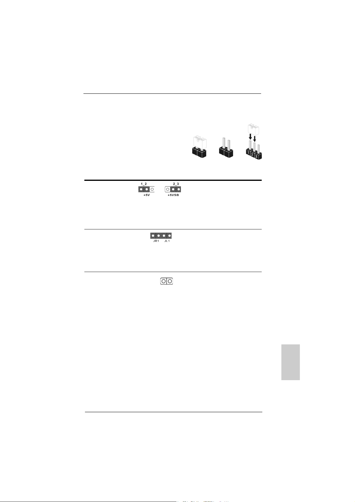
2.4 Setup de Jumpers2.4 Setup de Jumpers
2.4 Setup de Jumpers
2.4 Setup de Jumpers2.4 Setup de Jumpers
La ilustración muestra como los jumpers son
configurados. Cuando haya un jumper-cap
sobre los pins, se dice gue el jumper está
“Short”. No habiendo jumper cap sobre los
pins, el jumper está “Open”. La ilustración
muesta un jumper de 3 pins cuyo pin 1 y pin
2 están “Short”.
Jumper Setting
PS2_USB_PW1 Ponga en cortocircuito pin 2,
(vea p.2, No. 1) pin 3 para habilitar +5VSB
Atención: Para elegir +5VSB, se necesita corriente mas que 2 Amp proveida por la
fuente de electricidad.
Jumpers JR1JL1
(vea p.2, No. 24)
Atención: Si los jumpers JR1 y JL1 son cortos, los conectores de audio del panel
frontal y los del panel posterior podrán funcionar.
Limpiar CMOS
(CLRCMOS2, jumper de 2 pins)
(ver p.2, N. 18)
jumper de 2 pins
Short Open
(standby) para PS/2 o USB
wake up events.
Atención: CLRCMOS2 permite que Usted limpie los datos en CMOS. Los datos en
CMOS incluyen informacione s de la conf iguración del sistema, tales como
la contraseña del sistema, fecha, tie mpo, y parámetros de la conf iguración
del sistema. Para limpiar y reconfigurar los parametros del sistema a la
configuración de la fábrica, por favor apague el computador y desconecte
el cable de la fuente de electricidad, ponga en cortocircuito los pins de
CLRCMOS2 por más que 3 segundos usando un jumper cap. Por favor
acuérdase de quitar el jumper cap después de limpiar el COMS. Por favor
acuérdase de quitar el jumper cap después de limpiar el COMS. Si necesita
borrar la CMOS cuando acabe de finalizar la actualización de la BIOS,
debe arrancar primero el sistema y, a continuación, apagarlo antes de
realizar la acción de borrado de CMOS.
ASRock 939S56-M Motherboard
8181
81
8181
EspañolEspañol
EspañolEspañol
Español
Page 82

2.5 Cabezales y Conectores en Placas2.5 Cabezales y Conectores en Placas
2.5 Cabezales y Conectores en Placas
2.5 Cabezales y Conectores en Placas2.5 Cabezales y Conectores en Placas
Los conectores no son jumpers. Por favor no ponga jumper caps
sobre los conectores. El colocar cubiertas de puentes sobre los
conectores provocará un daño permanente en la placa base.
Conector Figure Descripción
Conector de disquetera
(33-pin FLOPPY1)
(vea p.2, No. 21)
la banda roja debe quedar en
el mismo lado que el contacto 1
Atención: Asegúrese que la banda roja del cable queda situado en el mismo lado que
el contacto 1 de la conexión.
IDE conector primario (azul) IDE conector secundario (negro)
(39-pin IDE1, vea p.2, No. 8) (39-pin IDE2, vea p.2, No. 7)
Conector azul Conector negro
a placa madre a aparato IDE
Cable ATA 66/100/133 de conducción 80
Atención: Si utiliza solamente un dispositivo IDE en esta placa base, configúrelo
como “maestro”. Consulte las instrucciones del distribuidor del dispositivo
IDE para conocer los detalles. Además, para optimizar la compatibilidad y
el rendimiento, conecte el disco duro a la conexión IDE primaria,
(IDE1, azul) y el CD-ROM a la conexión IDE secundaria (IDE2, negra).
Español
EspañolEspañol
EspañolEspañol
8282
82
8282
Conexiones de serie ATA Estas dos conexiones de serie
(SAT A1: vea p.2, No. 1 1) ATA (SATA) admiten cables
(SAT A2: vea p.2, No. 12) SATA para dispositivos de
SAT A1
almacenamiento internos. La
SAT A2
interfaz SATA actual permite
una velocidad de transferencia
de 1.5 Gb/s.
Cable de datos de Ambos extremos del cable
serie ATA (SATA) pueden conectarse al disco
duro SATA o la conexión de la
placa base.
ASRock 939S56-M Motherboard
Page 83

Cable de alimenta ción Conecte el extremo negro del
de serie ATA (SATA) cable de SATA al conector de
(Opcional) energía de la unidad. A
continuación, conecte el
extremo blanco del cable de
alimentación SATA a la
conexión de alimentación de la
fuente de alimentación.
Cabezal USB 2.0 ASRock 8CH I/O le proporciona
(9-pin USB67) 4 puertos USB 2.0
(ver p.2, No. 16) predeterminados en el panel
posterior. Si los puertos USB
posteriores no son suficientes,
este cabezal USB 2.0 (USB67)
se encuentra disponible para
admitir 2 puertos USB 2.0
adicionales.
Cabezal USB 2.0 ASRock 8CH I/O le proporciona
(9-pin USB_H4_5) 4 puertos USB 2.0
(ver p.2, No. 17) predeterminados en el panel
posterior. Si los puertos USB
posteriores no son suficientes,
este cabezal USB 2.0
(USB_H45) se encuentra
disponible para admitir 2
puertos USB 2.0 adicionales.
Cabezal de módulo Infrared Soporta módulo Infrared de
(5-pin IR1) transmisión y recepción
(vea p.2, No. 19) wireless.
Conector de Audio Interno Permite recepción de input
(4-pin CD1) audio de fuente sónica como
(CD1: vea p.2, No. 28) CD-ROM, DVD-ROM, TV tuner,
CD1
o tarjeta MPEG.
ASRock 939S56-M Motherboard
8383
83
8383
EspañolEspañol
EspañolEspañol
Español
Page 84

Conector de audio de panel Este es una interface para
frontal cable de audio de panel frontal
(9-pin AUDIO1) que permite conexión y control
(vea p.2, No. 23) conveniente de apparatos de
Audio.
Conector del Panel del Este conector acomoda varias
systema funciones de panel frontal del
(9-pin PANEL1) systema.
(vea p.2, No. 13)
Cabezal del altavoz del chasis Conecte el altavoz del chasis a
(4-pin SPEAKER1) su cabezal.
(vea p.2, No. 14)
Conector del ventilador Conecte el cable del ventilador
del chasis del chasis a este conector y
(3-pin CHA_FAN1) haga coincidir el cable negro
(vea p.2, No. 15) con el conector de tierra.
Conector del ventilador Conecte el cable del ventilador
de la CPU de la CPU a este conector y
(3-pin CPU_FAN1) haga coincidir el cable negro
(vea p.2, No. 30) con el conector de tierra.
Cabezal de alimentación ATX Conecte la fuente de
(20-pin ATXPW R1) alimentación ATX a su cabezal.
(vea p.2, No. 29)
Español
EspañolEspañol
EspañolEspañol
8484
84
8484
Conector de ATX 12V power Tenga en cuenta que es
(4-pin A TX12V1) necesario conectar este
(vea p.2, No. 2) conector a una toma de corriente
con el enchufe ATX 12V, de
modo que proporcione suficiente
electricidad. De lo contrario no
se podrá encender.
Conexión de juegos Conecte un cable de juegos a
(15-pin GAME1) esta conexión si se instala el
(vea p.2, No. 22) soporte del puerto de juegos.
ASRock 939S56-M Motherboard
Page 85

2.62.6
Instalación de discos duro AInstalación de discos duro A
2.6
Instalación de discos duro A
2.62.6
Instalación de discos duro AInstalación de discos duro A
Configuración RAIDConfiguración RAID
Configuración RAID
Configuración RAIDConfiguración RAID
Esta placa madre es compatible con los discos duros Serial ATA (SATA) y con las
funciones RAID (incluyendo RAID0, RAID1 y JBOB). En seta sección obtendrá
instrucciones para los discos duros SATA.
PASO 1: Instale los discos duros SATA dentro de las bahías para unidades del
chasis.
PASO 2: Conecte el cable de alimentación SATA al disco duro SATA.
PASO 3: Conecte un extremo del cable de datos SATA al conector SATA de la
placa base.
PASO 4: Conecte el otro extremo del cable de datos SATA al disco duro SATA.
1. Si piensa utilizar RAID 0, RAID 1, JBOD funciona sobre SATA, SATA Los
discos duros deben operarse en el modo “RAID”.
2. El modo “RAID” Y “no RAID” son opciones bajo el “Modo de funcionamiento
SATA” en la configuración de la BIOS. Consulte la página 28 para conocer
los detalles. Se necesitan controladores diferentes durante la operación real.
2.72.7
FF
2.7
2.72.7
La placa madre 939S56-M admite la función Hot Plug para dispositivos SATA.
unción Hot Plug para unidades de disco duro SAunción Hot Plug para unidades de disco duro SA
F
unción Hot Plug para unidades de disco duro SA
FF
unción Hot Plug para unidades de disco duro SAunción Hot Plug para unidades de disco duro SA
¿Qué es la función Hot Plug?
Si una unidad de disco duro SATA NO está definida para una
configuración RAID, se denomina “Hot Plug” a la acción de insertar
y retirar dicha unidad de disco duro SATA mientras el sistema se
encuentra encendido y funcionando. En cualquier caso, tenga en
cuenta que no se puede efectuar un Hot Plug si el sistema
operativo se ha instalado en dicha unidad de disco duro SATA.
TT
A serie (SAA serie (SA
T
A serie (SA
TT
A serie (SAA serie (SA
TT
A) /A) /
T
A) /
TT
A) /A) /
TT
AA
T
A
TT
AA
ADVERTENCIA
Si bien esta placa madre admite la función Hot Plug para
dispositivos SATA, existen ciertas limitaciones. Asegúrese de leer
las instrucciones en el CD de soporte antes de utilizar la función
Hot Plug. Si no lo hace podría perder datos almacenados en la
unidad de disco duro SATA HDD o dañar la propia unidad de disco
duro SATA. Para obtener instrucciones detalladas, consulte el
documento en el CD de soporte en la siguiente ubicación:
..\ RAID BIOS Setting Utility
ASRock 939S56-M Motherboard
8585
85
8585
EspañolEspañol
EspañolEspañol
Español
Page 86

2.82.8
RR
2.8
2.82.8
Si desea instalar el sistema operativo Windows 2000, Windows XP, Windows XP
de 64 bits en sus discos duros SATA, tendrá que crear un controlador SATA
antes de iniciar la instalación del sistema operativo.
ealización de un disquete del controlador SAealización de un disquete del controlador SA
R
ealización de un disquete del controlador SA
RR
ealización de un disquete del controlador SAealización de un disquete del controlador SA
para la operación SApara la operación SA
para la operación SA
para la operación SApara la operación SA
PASO 1: Inserte el CD de soporte de ASRock en la unidad óptica de la
unidad para iniciar el sistema. (NO inserte ningún disquete en
la unidad de disco en este momento)
PASO 2: Durante la comprobación inicial (POST) del sistema, pulse la
tecla <F11> y aparecerá una ventana de selección de los
dispositivos de inicio. Seleccione el CD-ROM como unidad de
inicio.
PASO 4: A continuación podrá ver los siguientes mensajes:
Please insert a diskette into the floppy drive.
WARNING! Formatting the floppy diskette will
lose ALL data in it!
Start to format and copy files [YN]?
(Inserte un disquete en la unidad de disco
ADVER TENCIA! Dar formato a un disquete hará que se
pierda TODA la información contenida en él
¿Comenzar a dar formato y copiar los archivos [S/N]?)
Introduzca un disquete en la unidad de disco y pulse <Y>.
PASO 5: El sistema comenzará a formatear el disquete y copiar
controladores SATA en el disquete.
TT
A en el Modo “RAID”A en el Modo “RAID”
T
A en el Modo “RAID”
TT
A en el Modo “RAID”A en el Modo “RAID”
TT
AA
T
A
TT
AA
Español
EspañolEspañol
EspañolEspañol
8686
86
8686
Cuando tenga listo el disquete del controlador SATA, puede empezar a instalar
Windows 2000 / Windows XP / Windows XP 64-bit en su sistema directamente, sin
completar la configuración RAID, o bien empezar utilizando “SiS RAID BIOS Setting
Utility” (Utilidad de configuración de SiS RAID BIOS) para completar la configuración
de RAID 0 / RAID 1 / JBOD antes de instalar el sistema operativo. Antes de empezar
a configurar la función RAID, tendrá que consultar la guía de instalación incluida en el
CD de soporte para hacerlo correctamente. Consulte el documento del CD de
soporte, “Guide to SATA Hard Disks Installation and RAID Configuration,” (Guía de
instalación de discos duros SATA y configuración RAID) ubicado en la siguiente
carpeta:
.. \ RAID BIOS Setting Utility
También puede completar la configuración RAID utilizando “SiS RAID Utility for
Windows” (Utilidad SiS RAID para Windows) en el entorno Windows. Consulte el
documento del CD de soporte, “Guide to SiS RAID Utility for Windows,” (Guía de la
Utilidad SiS RAID para Windows) ubicada en la siguiente carpeta:
.. \ RAID Utility for Windows
ASRock 939S56-M Motherboard
Page 87

2.92.9
FF
uncionamiento de SAuncionamiento de SA
2.9
F
uncionamiento de SA
2.92.9
FF
uncionamiento de SAuncionamiento de SA
Si desea instalar el sistema operativo Windows 2000, Windows XP, Windows XP
de 64 bits en sus discos duros SATA que operan en modo no RAID, no será
necesario crear un controlador SATA antes de la instalación del sistema operativo.
Windows 98 SE y Windows ME deben instalarse con SA TA operando en
modo RAID y no es necesario crear un disquete de controlador SATA para
estos dos sistemas operativos antes de la instalación de los mismos.
3. BIOS Información3. BIOS Información
3. BIOS Información
3. BIOS Información3. BIOS Información
El Flash Memory de la placa madre deposita SETUP Utility. Durante el Power-Up
(POST) apriete <F2> para entrar en la BIOS. Sí usted no oprime ninguna tecla, el
POST continúa con sus rutinas de prueba. Si usted desea entrar en la BIOS
después del POST, por favor reinicie el sistema apretando <Ctl> + <Alt> +
<Borrar>, o apretando el botón Reset en el panel del ordenador.
El programa SETUP esta diseñado a ser lo mas fácil posible. Es un programa guiado
al menu, es decir, puede enrollarse a sus varios sub-menues y elegir las opciones
predeterminadas. Para información detallada sobre como configurar la BIOS, por
favor refiérase al Manual del Usuario (archivo PDF) contenido en el CD.
TT
A en “Modo no RAID”A en “Modo no RAID”
T
A en “Modo no RAID”
TT
A en “Modo no RAID”A en “Modo no RAID”
4.Información de Software Suppor4.Información de Software Suppor
4.Información de Software Suppor
4.Información de Software Suppor4.Información de Software Suppor
Esta placa-base soporta diversos tipos de sistema operativo Windows: 98SE / ME /
2000 / XP El CD de instalación que acompaña la placa-base trae todos los drivers y
programas utilitarios para instalar y configurar la placa-base.
Para iniciar la instalación, ponga el CD en el lector de CD y se desplegará el Menú
Principal automáticamente si «AUTORUN» está habilitado en su computadora.
Si el Menú Principal no aparece automáticamente, localice y doble-pulse en el archivo
ASSETUP.EXE para iniciar la instalación.
ASRock 939S56-M Motherboard
t CDt CD
t CD
t CDt CD
8787
87
8787
EspañolEspañol
EspañolEspañol
Español
Page 88

1. Introdução1. Introdução
1. Introdução
1. Introdução1. Introdução
Gratos por comprar nossa placa–mãe 939S56-M, um produto confiável feito com
ASRock um estrito controle de qualidade consistente. Com um excelente
desempenho, essa placa é dotada de um projeto robusto que atende a ASRock de
compromisso com a qualidade e durabilidade.
Este Guia de Instalação Rápida apresenta a placa-mãe e o guia de instalação
passo a passo. Mais informações detalhadas sobre a placa-mãe podem ser
encontradas no manual do usuário do CD de suporte.
Porque as especificações da placa mãe e o software de BIOS poderiam
ser atualizados, o conteúdo deste manual pode ser cambiado sem aviso.
Em caso de qualquer modificação deste manual, a versão atualizada
estará disponível no website de ASRock sem prévio aviso. Você também
poderá encontrar no website da ASRock, as últimas listas de suporte para
a Memória e CPU.
Website de ASRock
http://www.asrock.com
1.1 Este pacote contém
Placa-mãe ASRock 939S56-M
(Formato Micro ATX: 9,6 pol. x 8,8 pol., 24,4 cm x 22,4 cm)
Guia de instalação rápida da ASRock 939S56-M
CD de suporte da placa ASRock 939S56-M
Um cabo-fita IDE Ultra ATA 66/100/133 de 80 condutores
Um cabo-fita para unidade de disquete de 3,5 pol.
Um cabo de dados ATA Serial (SATA) (opcional)
Um cabo de alimentação para unidade de disco rígido ATA Serial (SATA)
(opcional)
Uma proteção ASRock 8CH I/O
Português
PortuguêsPortuguês
PortuguêsPortuguês
8888
88
8888
ASRock 939S56-M Motherboard
Page 89

1.2 Especificações1.2 Especificações
1.2 Especificações
1.2 Especificações1.2 Especificações
Plataforma: Formato Micro ATX: 9,6 pol. x 8,8 pol., 24,4 cm x 22,4 cm
CPU: Soquete de 939 pinos compatível com processador AMD Athlon™
64 / 64FX / 64 X2
Suporta a tecnologia AMD Cool ‘n’ Quiet™ (veja o AVISO 1)
Chipsets: North Bridge: Chipset SiS 756
FSB @ 1GHz (2.0 GT/s) / 800 MHz
Suporta a tecnologia Untied Overclocking
(veja o AVISO 2)
South Bridge: Chipset SiS 965L
Suporta USB 2.0, ATA 133, SATA 1,5 Gb/s
Memória: 4 slots para DDR DIMM: DDR1, DDR2, DDR3 e DDR4
PC3200 (DDR400) / PC2700 (DDR333) / PC2100 (DDR266),
Máx. 4GB
IDE: IDE1: ATA133 / Ultra DMA Mode 6,
IDE2: ATA133 / Ultra DMA Mode 6,
Suporta até 4 dispositivos IDE
ATA Serial: 2 conectores SATA, suporte a taxa de transferência de dados
de até 1,5 Gb/s
Porta para disquete:
Suporta até 2 unidades de disquete
Áudio: 7.1 canais de áudio AC’97
LAN: Velocidade: 802.3u (10/100 Ethernet), suporta Wake-On-LAN
Monitor do HW: Sensores de temperature do procesador;
Medição de temperatura da placa-mãe;
Deligamento automático em caso de superaquecimento do
processador, para prote ção da vida útil do processador
(veja o AVISO 3);
Tacômetros de ventilador do Processador;
Tacômetros de ventilador do chassis;
Monitoramento de voltagem : +12 V, +5 V, +3.3 V, Vcore
Slots PCI: 2 slots de PCI com especificação 2.2
Slots PCI Express: 1 ranhura com PCIE x 1, 1 ranhura com PCIE x 16;
Especificação PCIE 1.0a
USB 2.0: 8 portas USB 2.0:
inclui 4 portas padrão USB 2.0 no painel traseiro,
mais um conector para suportar 4 portas USB 2.0 adicionais
(veja o AVISO 4)
ASRock 8CH I/O:1 porta para mouse PS/2, 1 porta para teclado PS/2,
1 porta serial: COM1,
1 porta paralela (com suporte ECP/EPP),
1 porta RJ-45, 4 portas USB 2.0 padrão,
ASRock 939S56-M Motherboard
8989
89
8989
PortuguêsPortuguês
PortuguêsPortuguês
Português
Page 90

Português
PortuguêsPortuguês
PortuguêsPortuguês
Áudio Jack: Altifalante lateral / Altifalante traseiro / Central/Graves
/ Entrada de linha / Altifalante frontal / Microfone
(veja o AVISO 5)
BIOS: BIOS AMI, suporta dispositivos “Plug and Play”,
ACPI 1.1 atendendo a eventos de “wake up”,
suporte para SMBIOS 2.3.1,
frequência da CPU com controle contínuo (somente para
referência a usuários avançados, veja o AVISO 6)
Sistema Operacional: Microsoft® Windows® 98SE / ME / 2000 / atende a XP
AVISO!
1. Para poupar energia, recomendamos vivamente a activação da
tecnologia Cool ‘n’ Quiet da AMD no sistema Windows. Consulte o
APÊNDICE na página 37 do “Manual do utilizador” no CD de suporte
para activar a tecnologia Cool ‘n’ Quiet da AMD.
2. Esta placa principal suporta a tecnologia Untied Overclocking. Durante
o overclocking, o FSB é separado dos buses PCIE e PCI. Por outras
palavras, o FSB da CPU é separado durante o overclocking, mas os
buses PCIE e PCI permanecem fixos para que o FSB possa funcionar
num ambiente de overclocking mais estável.
3. Assim que se detecta um superaquecimento na CPU, o sistema se
desliga automaticamente e o botão de energia do chassis fica inativo.
Cheque o ventilador da CPU na placa–mãe, para verificar se está
funcionando corretamente antes de religar o sistema. Para melhorar a
dissipação de calor, lembre-se de aplicar o material de interface térmica
entre o processador e o dissipador de calor.
4. Power Management para USB 2.0 funciona bem embaixo de Microsoft
Windows® XP SP1/2000 SP4. É possível que não trabalhe corretamente
embaixo de Microsoft 98/ME.
5. Em termos do microfone, esta placa-principal suporta ambos os modos
estéreo e mono. Quanto à saída de áudio, esta placa-principal suporta
os modos de 2, 4, 6 e 8 canais. Consulte a tabela na página 3 para uma
ligação correcta.
6. Apesar de esta placa-mãe oferecer controle continuamente variável,
não se recomenda efetuar over-clock. Freqüências de barramento
diferentes das recomendadas para a CPU podem provocar instabilidade
do sistema ou danos à CPU.
®
9090
90
9090
ASRock 939S56-M Motherboard
Page 91
2. Instalação2. Instalação
2. Instalação
2. Instalação2. Instalação
Precauções antes da instalaçãoPrecauções antes da instalação
Precauções antes da instalação
Precauções antes da instalaçãoPrecauções antes da instalação
Siga as precauções à seguir antes de instalar os componentes ou
fazer qualquer ajuste na placa mãe.
1. Desligue o cabo de força da rede elétrica antes de tocar em
qualquer componente. A falta desta precaução, a pessoa pode
causar sérios danos à placa–mãe, periféricos e / ou componentes
do sistema.
2. Para evitar danos a componentes da placa–mãe por eletricidade
estática, NUNCA coloque a placa–mãe diretamente sobre um
carpete ou tapete ou similar. Lembre–se também de usar sempre
uma pulseira aterrada ou tocar uma placa de descarga
eletrostática de segurança antes de manusear qualquer
componente.
3. Segure os componentes pelas bordas, nunca toque nos IC’s.
4. Ao instalar qualquer componente, primeiro coloque–o sobre um
suporte anti estático aterrado ou na própria embalagem do
componente.
5. Ao instalar parafusos nos furos para fixar a placa-mãe ao chassi,
não os aperte excessivamente para não danificar a placa-mãe.
2.1 Instalação da CPU2.1 Instalação da CPU
2.1 Instalação da CPU
2.1 Instalação da CPU2.1 Instalação da CPU
1º passo: destrave o soquete levantando a alavanca de trava em um ângulo de 90°.
2º passo: posicione a CPU diretamente sobre o soquete, de tal forma que seu canto
com a marca se alinhe com a base da alavanca do soquete.
3º passo: insira com cuidado a CPU no soquete até que ela se encaixe no lugar.
A CPU somente se encaixa em uma posição correta. NÃO force a
CPU no soquete, para evitar que os pinos fiquem tortos.
4º passo: quando a CPU estiver encaixada no lugar, pressione firmemente o soquete
ao mesmo tempo em que abaixa a alava nca para travar a CPU. Ao chegar
à posição correta, a alavanca clica na aba lateral, indicando que está
travada.
5º passo: instale o ventilador da CPU e o dissipador de calor. Para fazer uma
instalação correta, consulte antes os manuais de instrução dos fabricantes
da CPU e do dissipador de calor.
ASRock 939S56-M Motherboard
9191
91
9191
PortuguêsPortuguês
PortuguêsPortuguês
Português
Page 92

2.2 Instalação dos Módulos de Memória (DIMM)2.2 Instalação dos Módulos de Memória (DIMM)
2.2 Instalação dos Módulos de Memória (DIMM)
2.2 Instalação dos Módulos de Memória (DIMM)2.2 Instalação dos Módulos de Memória (DIMM)
A 939S56-M possui quatro slots DIMM DDR (taxa de dados dupla) de 184 pinos e
suporta a tecnologia de memória de duplo canal. Para a configuração de duplo canal,
instale sempre um par idêntico de DIMM DDR (mesma marca, tipo, tamanho e tipo de
chip) nos slots de mesma cor. Ou seja, é preciso instalar um par idêntico de DIMM
DDR no duplo canal A (DDR1 e DDR2; slots azuis; veja a folha 2, No. 5) ou um par
idêntico de DIMM DDR no duplo ca nal B (DD R3 e DDR4; slots pretos; veja a f olha 2, No.
6), para que a tecnologia de memória de duplo canal possa ser ativada. Esta placa
também permite instalar quatro módulos DIMM DDR para a configuração de duplo
canal e, instale módulos DIMM DDR idênticos nos quatro slots. Esta placa-principal
permite-lhe também instalar quatro DIMMs DDR para uma configuração de canal
duplo, instale DIMMs DDR idênticos nas quatro ranhuras. Consulte a tabela de
configuração da memória de canal duplo em baixo.
Configurações da Memória de Canal Duplo
DDR1 DDR2 DDR3 DDR4
(Slot Azuis) (Slot Azuis) (Slot Pretos) (Slot Pretos)
(1)
Ocupada Ocupada
(2)
(3)
* Em termos da configuração (3), instale DIMMs DDR idênticos nas quatro ranhuras.
* Recomendamos que seja feita, em primeiro lugar, a instalação dos módulos DDR1
e DDR2. De seguida, proceda à instalação dos módulos DDR3 e DDR4.
_ _
Ocupada Ocupada
__
Ocupada Ocupada
Ocupada Ocupada
Português
PortuguêsPortuguês
PortuguêsPortuguês
9292
92
9292
1. Se quiser instalar dois módulos de memória diferentes e obter uma
compatibilidade e uma fiabilidade óptimas, recomendamos a instalação
dos módulos em ranhuras de cores diferentes. Por outras palavras, instale os quer na ranhura DDR1 ou DDR3.
2. Se apenas instalar um módulo de memória ou três módulos de memória nas
ranhuras DIMM DDR desta placa-principal, não será possível activar a
tecnologia de memória de canal duplo.
3. Se NÃO instalar um par de módulos de memória no mesmo canal duplo, ou
seja, se não instalar um par de módulos de memória na ranhura DDR1 e
DDR3, não será possível activar a tecnologia de memória de canal duplo.
ASRock 939S56-M Motherboard
Page 93

Instalando uma DIMMInstalando uma DIMM
Instalando uma DIMM
Instalando uma DIMMInstalando uma DIMM
Certifique-se de desconectar a fonte de alimentação antes de adicionar
ou remover módulos DIMM ou outros componentes do sistema.
1º passo: destrave um slot de DIMM puxando para fora os seus clipes de retenção.
2º passo: alinhe a DIMM no slot de forma que o entalhe da DIMM fique alinha do com
a ranhura no slot.
A DIMM somente se encaixa em uma orientação correta.
Se for forçada no slot em uma orientação incorreta, haverá danos
permanentes à placa-mãe e à DIMM.
3º passo: Insira a DIMM firmemente no slot até que os clipes de retenção em ambos
os lados se encaixem totalmente em seus locais e a DIMM esteja encaixada
de modo apropriado.
ASRock 939S56-M Motherboard
9393
93
9393
PortuguêsPortuguês
PortuguêsPortuguês
Português
Page 94

2.3 Slots de Expansão (Slots de PCI e PCI Express)2.3 Slots de Expansão (Slots de PCI e PCI Express)
2.3 Slots de Expansão (Slots de PCI e PCI Express)
2.3 Slots de Expansão (Slots de PCI e PCI Express)2.3 Slots de Expansão (Slots de PCI e PCI Express)
Há 2 slots de PCI e 2 de PCI Express na placa–mãe do 939S56-M.
Slots PCI: Os slots PCI se usam para instalar placas de expansão com uma
interface de PCI de 32 bit.
Slot PCI Express: A especificação PCIE1 (ra nhura PCIE x16) é utiliza da para as
placas gráficas PCI Express x16. A especificação PCIE2
(ranhura PCIE x1) é utilizada para as placas PCI Express,
como é o caso das placas Gigabit LAN, SATA II, etc.
Instalando uma placa de expansãoInstalando uma placa de expansão
Instalando uma placa de expansão
Instalando uma placa de expansãoInstalando uma placa de expansão
1º passo: Antes de instalar a placa de expansão, certifique-se que a fonte de
alimentação esteja desligada ou que o cabo de energia elétrica esteja
desconectado. Favor ler a documentação da placa de expansão e faça
as configurações de hardware adequadas para a placa antes de iniciar a
instalação.
2º passo: Retire a tampa que cobre o slot que você deseja usar; reserve os parafusos
para uso futuro.
3º passo: Alinhe o conector da placa com o slot e pressiona com firmeza, até que a
placa esteja totalmente encaixada no slot.
4º passo: Aparafuse a placa no chassis com os parafusos.
Português
PortuguêsPortuguês
PortuguêsPortuguês
9494
94
9494
ASRock 939S56-M Motherboard
Page 95
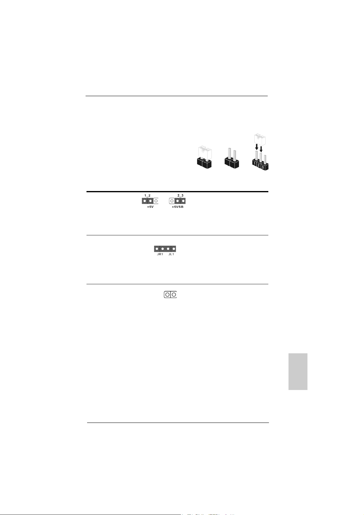
2.4 Configuração dos Jumpers2.4 Configuração dos Jumpers
2.4 Configuração dos Jumpers
2.4 Configuração dos Jumpers2.4 Configuração dos Jumpers
A ilustração mostra como os jumpers são
configurados. Quando há uma capa de
jumpers sobre os pinos, diz–se que o jumper
está “curto”. Não havendo capa sobre os
pinos, o jumper está “aberto”. A ilustração
mostra um jumper de 3 pinos em que os pinos
1 e 2 están “curtos” quando a capa de jumper
estiver colocada sobre esses 2 pinos.
Jumper Configuração
PS2_USB_PW1 Pin2, Pin3 curtos para
(veja a folha 2, No. 1) habilitar +5VSB (stand by)
Nota: Para escolher +5VSB, é preciso uma corrente de stand by de 2 A ou mais.
Jumpers JR1JL1
(veja a folha 2, No. 24)
Nota: Se os jumpers JR1 e JL1 estiverem fechados, os conectores de áudio dos
painéis frontal e traseiro serão funcionais.
Restaurar CMOS
(CLRCMOS2, jumper de 2 pinos)
(veja a folha 2, No. 18)
jumper de 2 pinos
Short Open
para PS/2 ou eventos de
wake up na USB.
Nota: CLRCMOS2 permite você limpar os dados em CMOS. Os dados em CMOS
incluem informações da configuração do sistema como: por exemplo a senha
do sistema, data, tempo, e os parámetros da configuração do sistema. Para
limpar e reconfigurar os parámetros do sistema a configuração inicial da
fábrica, por favor desligue o cabo de força, ponha em curto–circuito os pins
de CLRCMOS2 por mais de 3 segundos para limpar o CMOS usando um
jumper. Por favor lembrese de remover o jumper depois de limpar o COMS. Se
precisar limpar o CMOS ao concluir a atualização do BIOS, deverá reiniciar o
sistema primeiro e, em seguida, desligá-lo antes de executar a ação de limpeza
o CMOS.
ASRock 939S56-M Motherboard
9595
95
9595
PortuguêsPortuguês
PortuguêsPortuguês
Português
Page 96

2.5 Conectores2.5 Conectores
2.5 Conectores
2.5 Conectores2.5 Conectores
Os conectores NÃO SÃO jumpers. NÃO coloque capas de jumper sobre
estes conectores. A colocação de pontos de jumper sobre os conectores
causará danos irreversíveis à placa-mãe.
Conector Figura Descrição
Conector FDD
(FLOPPY 1, 33 pinos)
(veja a folha 2, No. 21)
o lado com listras vermelhas para o Pino 1
Nota: Certifique-se de que o lado com listras vermelhas no cabo seja conectado ao
lado Pino 1 do conector.
Conector primário (azul) Conector secundário de IDE (preto)
(IDE1 de 39 pinos, veja a folha 2, No. 8) (IDE2 de 39 pinos, veja a folha 2, No. 7)
Ligue esta ponta (azul) Ligue esta ponta (preta)
à placa–mãe aos dispositivos IDE
Cabo ATA 66/100/133 de 80 condutores
Nota: Se for usado apenas um dispositivo IDE nesta placa-mãe, configure-o como
“Master”. Para detalhes, consulte as instruções do fornecedor do seu
dispositivo IDE. Ainda, para otimizar a compatibilidade e o desempenho, conecte
a unidade de disco rígido ao conector IDE primário (IDE1, azul) e a unidade de
CD-ROM ao conector IDE secundário (IDE2, preto).
Português
PortuguêsPortuguês
PortuguêsPortuguês
9696
96
9696
Conectores ATA Serial Estes dois conectores Serial
(SAT A1: veja a folha 2, No. 1 1) ATA (SATA) suportam cabos
(SAT A2: veja a folha 2, No. 12) de dados SATA para os
SAT A1
SAT A2
dispositivos de
armazenamentos internos. A
atual interface SATA permite
uma taxa de transferência de
dados de até 1.5 Gb/s.
Cabo de dados Tanto a saída do cabo de Serial
ATA (SATA) dados SATA pode ser
conectado ao disco rígido
SATA quanto o conector SATA
na placa mãe.
ASRock 939S56-M Motherboard
Page 97

Cabo de Alimentação Conecte a saída de cor preta
ATA (SATA) do cabo de alimentação SATA
(opcional) ao conector de alimentação
Ligue no conector de
alimentação SATA HDD
Conecte a fonte
em cada acionador. Em
seguida, conecte a saída
branca do cabo de alimentação
SATA ao conector de
alimentação da fonte.
Cabezal USB 2.0 ASRock 8CH I/O le proporciona
(9-pin USB67) 4 puertos USB 2.0
(ver p.2, No. 16) predeterminados en el panel
posterior. Si los puertos USB
posteriores no son suficientes,
este cabezal USB 2.0 (USB67)
se encuentra disponible para
admitir 2 puertos USB 2.0
adicionales.
Cabezal USB 2.0 ASRock 8CH I/O le proporciona
(9-pin USB_H45) 4 puertos USB 2.0
(ver p.2, No. 17) predeterminados en el panel
posterior. Si los puertos USB
posteriores no son suficientes,
este cabezal USB 2.0
(USB_H45) se encuentra
disponible para admitir 2
puertos USB 2.0 adicionales.
Conector do módulo de Este conector suporta um
infravermelho módulo opcional de
(IR1 de 5 pinos) transmissão sem fio e
(veja a folha 2, No. 19) recepção em infravermelho.
Conectores internos de áudio Estes conectores permitem
(CD1 de 4 pinos) que se receba entrada de
(CD1: veja a floha 2, No. 28) áudio em estéreo de fontes
CD1
de áudio como CD-ROM,
DVD-ROM, placa sintonizadora
de TV ou pla ca MPEG.
ASRock 939S56-M Motherboard
9797
97
9797
PortuguêsPortuguês
PortuguêsPortuguês
Português
Page 98

Conector Áudio do painel Esta é uma interface para o
frontal cabo de áudio no painel frontal,
(AUDIO1 de 9 pinos) que permite uma conexão e
(veja a folha 2, No. 23) controle convenientes dos
dispositivos de áudio.
Conector do sistema no Este conector acomoda
painel diversas funções de
(PANEL1 de 9 pinos) sistema no painel frontal.
(veja a folha 2, No. 13)
Conector do alto-falante Ligue o alto-falante do chassi
do chassi neste conector.
(SPEAKER1 de 4 pinos)
(veja a folha 2, No. 14)
Conector do ventilador do Ligue o cabo do ventilador neste
chassis conector, coincidindo o fio preto
(CHA_FAN1 de 3 pinos) com o pino de aterramento.
(veja a folha 2, No. 15)
Conector do ventilador da Ligue o cabo do ventilador da
C PU CPU, coincidindo o fio preto com
(CPU_FAN1 de 3 pinos) o pino de aterramento.
(veja a folha 2, No. 30)
Português
PortuguêsPortuguês
PortuguêsPortuguês
9898
98
9898
Conector de força do ATX Ligue a fonte de alimentação
(ATXPWR1 de 20 pinos) ATX neste conector.
(veja a folha 2, No. 29)
Conector A TX 12 V Note que é necessário ligar
(ATX12V1 de 4 pinos ) uma fonte de alimentação com
(veja a folha 2, No. 2) conector ATX 12V neste
conector para fornecer
alimentação suficiente. Do
contrário, haverá falhas de
funcionamento.
ASRock 939S56-M Motherboard
Page 99

Conector de jogos Ligue um cabo de jogos a este
(GAME1 de 15 pinos) conector se o suporte de porta
(veja a folha 2, No. 22) de jogos estiver instalado.
2.62.6
Instalação de discos rígidos AInstalação de discos rígidos A
2.6
Instalação de discos rígidos A
2.62.6
Instalação de discos rígidos AInstalação de discos rígidos A
Esta placa-principal suporta discos rígidos SATA (Serial ATA ) e as funções RAID
(incluindo RAID0, RAID1, e JBOB). Esta secção explica-lhe como instalar os
discos rígidos SATA.
1º passo: Instale o disco rígido SATA no compartimento de acionadores no
gabinete.
2º passo: Conecte o cabo de alimentação SATA ao respectivo disco rígido.
3º passo: Conecte uma extremidade do cabo de dados SATA ao conector SATA
da placa-mãe.
4º passo: Conecte a outra extremidade do cabo de dados SATA ao disco rígido
SATA.
1. Se pretender utilizar as funções RAID 0, RAID 1 ou JBOD em unidades de
disco rígido SATA, estas unidades têm de ser operadas no modo “RAID”.
2. Os modos “RAID” e “non-RAID” são opções que existem em “SATA
Operation Mode” (Modo de funcionamento SATA) na configuração da BIOS.
Consulte a página 28 para mais informações. São necessários
controladores diferentes durante o funcionamento.
TT
A Serial (SAA Serial (SA
T
A Serial (SA
TT
A Serial (SAA Serial (SA
TT
A)A)
T
A)
TT
A)A)
2.72.7
Função e conexão a quente para unidades de discosFunção e conexão a quente para unidades de discos
2.7
Função e conexão a quente para unidades de discos
2.72.7
Função e conexão a quente para unidades de discosFunção e conexão a quente para unidades de discos
rígidos SArígidos SA
rígidos SA
rígidos SArígidos SA
A placa-mãe 939S56-M suporta a função de conexão a quente de dispositivos
SATA.
TT
AA
T
A
TT
AA
O que é a função de conexão a quente?
Se as unidades de disco rígido SATA não forem configuradas para
RAID, chama-se “conexão a quente” o ato de inserir e retirar essas
unidades de disco rígido SATA com o sistema ligado e funcionando.
Note, no entanto, que não essa função não pode ser usada se o
sistema operacional estiver instalado na própria unidade de disco
rígido SAT A.
ASRock 939S56-M Motherboard
9999
99
9999
PortuguêsPortuguês
PortuguêsPortuguês
Português
Page 100

Português
PortuguêsPortuguês
PortuguêsPortuguês
ATENÇÃO!
Embora esta placa-mãe suporte a função de conexão a quente em
dispositivos SATA, ainda existem certas limitações. Não deixe de
ler a instrução no CD de suporte antes de usar essa função. Caso
contrário, estará arriscando perde as informações contidas nas
unidades de disco rígido SATA ou danificá-las. Consulte as
instruções detalhadas no documento do CD de suporte, como
segue:
..\ RAID BIOS Setting Utility
2.82.8
Criação de uma disquete do controlador SACriação de uma disquete do controlador SA
2.8
Criação de uma disquete do controlador SA
2.82.8
Criação de uma disquete do controlador SACriação de uma disquete do controlador SA
utilização da especificação SAutilização da especificação SA
utilização da especificação SA
utilização da especificação SAutilização da especificação SA
Se quiser instalar o sistema operativo Windows 2000, Windows XP ou Windows
XP de 64 bits nas suas unidades de disco rígido SATA, terá de criar uma disquete
do controlador SATA antes de iniciar a instalação do sistema operativo.
1º passo: Insira o CD ASRock Support no acionador ótico para reiniciar seu
sistema. (NÃO insira nenhum disquete no acionador de disquete
neste momento!)
2º passo: Durante o POST no início do boot do sistema, tecle o botão <F11>
depois uma janela de seleção de dispositivos de boot aparecerá.
Selecione o CD-ROM como o dispositivo de boot.
3º passo: Quando ler a mensagem na tela, “Do you want to generate Serial
ATA driver diskette [Y/N]?” (Deseja criar um disquete de driver
Serial ATA [Y/N]?), tecle <Y>.
4º passo: Então você lerá estas mensagens,
Please insert a diskette into the floppy drive.
WARNING! Formatting the floppy diskette will lose
ALL data in it!
Start to format and copy files [Y/N]?
(Insira no driver de disquete.
CUIDADO! Ao formatar o disquete TODOS os dados serão
perdidos!
Iniciar a formatação e a cópia dos arquivos [Y/N]?”)
Insira o disquete no driver de disquetes e tecle <Y>.
5º passo: O sistema iniciará a formatação do disquete e a cópia dos drivers
SAT A HDD.
TT
A no modo “RAID”A no modo “RAID”
T
A no modo “RAID”
TT
A no modo “RAID”A no modo “RAID”
TT
A paraA para
T
A para
TT
A paraA para
100100
100
100100
Quando tiver a disquete do controlador SATA pronta, pode instalar o Windows 2000 /
Windows XP / Windows XP de 64 bits directamente no seu sistema sem ter de
configurar as funções RAID, ou pode utilizar o “SiS RAID BIOS Setting Utility” para
configurar as funções RAID 0 / RAID 1 / JBOD antes de instalar o sistema operativo.
Antes de iniciar a configuração das funções RAID, terá de consultar o guia de
instalação existente no CD de suporte para garantir uma configuração correcta.
ASRock 939S56-M Motherboard
 Loading...