

Page 1
Copyright Notice:Copyright Notice:
Copyright Notice:
Copyright Notice:Copyright Notice:
No part of this installation guide may be reproduced, transcribed, transmitted, or
translated in any language, in any form or by any means, except duplication of
documentation by the purchaser for backup purpose, without written consent of
ASRock Inc.
Products and corporate names appearing in this guide may or may not be registered
trademarks or copyrights of their respective companies, and are used only for
identification or explanation and to the owners’ benefit, without intent to infringe.
Disclaimer:Disclaimer:
Disclaimer:
Disclaimer:Disclaimer:
Specifications and information contained in this guide are furnished for informational
use only and subject to change without notice, and should not be constructed as a
commitment by ASRock. ASRock assumes no responsibility for any errors or
omissions that may appear in this guide.
With respect to the contents of this guide, ASRock does not provide warranty of any
kind, either expressed or implied, including but not limited to the implied warranties or
conditions of merchantability or fitness for a particular purpose.
In no event shall ASRock, its directors, officers, employees, or agents be liable for
any indirect, special, incidental, or consequential damages (including damages for
loss of profits, loss of business, loss of data, interruption of business and the like),
even if ASRock has been advised of the possibility of such damages arising from any
defect or error in the guide or product.
This device complies with Part 15 of the FCC Rules. Operation is subject to the
following two conditions:
(1) this device may not cause harmful interference, and
(2) this device must accept any interference received, including interference that
may cause undesired operation.
ASRock Website: http://www.asrock.com
Published June 2006
Copyright©2006 ASRock INC. All rights reserved.
ASRock 939Dual-VSTA Motherboard
EnglishEnglish
EnglishEnglish
English
11
1
11
Page 2
Motherboard LMotherboard L
Motherboard L
Motherboard LMotherboard L
ayoutayout
ayout
ayoutayout
English
EnglishEnglish
EnglishEnglish
22
2
22
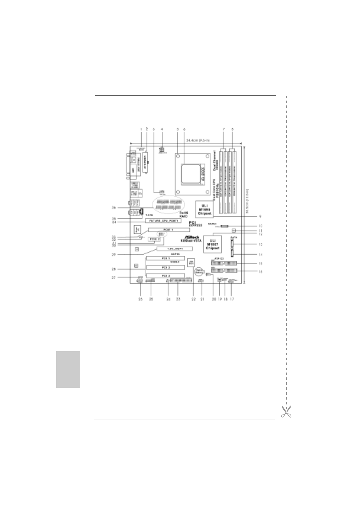
1 PS2_USB_PWR1 Jumper 18 Chassis Speaker Header (SPEAKER 1)
2 ATX Power Connector (ATXPWR1) 19 Chassis Fan Connector (CHA_FAN1)
3 CPU Fan Connector (CPU_FAN1) 20 Clear CMOS Jumper (CLRTC1)
4 A TX 12V Power Connector (A TX12V1) 21 USB 2.0 Header (USB45, Blue)
5 CPU Heatsink Retention Module 22 Flash Memory
6 939-Pin CPU Socket 23 Floppy Connector (FLOPPY1)
7 2 x 184-pin DDR DIMM Slots 24 Infrared Module Header (IR1)
(Dual Channel A: DDR1, DDR2; Blue) 25 Game Port Header (GAME1)
8 2 x 184-pin DDR DIMM Slots 26 Front Panel Audio Header (AUDIO1)
(Dual Channel B: DDR3, DDR4; Black) 27 JR1 / JL1 Jumper
9 North Bridge Controller 28 PCI Slots (PCI1- 3)
10 Serial A T AII Connector (SA T AII_1, red) 29 AGP Slot (1.5V_AGP1)
11 JMicron JMB360 Chipset (PCIE x1 interface) 30 J9 / J10 Jumper
12 South Bridge Controller 31 PCI Express x1 Slot (PCIE2)
13 Secondary Serial A T A Conne ctor (SA T A2 ) 32 J11 Jumper
14 Primary Serial A T A Connector (SATA1) 3 3 PCI Express x16 Slot (PCIE1)
15 Primary IDE Connector (IDE1, Blue) 34 Future CPU Port (FUTURE_CPU_PORT1)
16 Secondary IDE Connector (IDE2, Black) 35 Internal Audio Connector: CD1 (Black)
17 System Panel Header (PANEL1) 36 J1-J8 Jumpers
ASRock 939Dual-VSTA Motherboard
Page 3
ASRock 8CH I/OASRock 8CH I/O
ASRock 8CH I/O
ASRock 8CH I/OASRock 8CH I/O
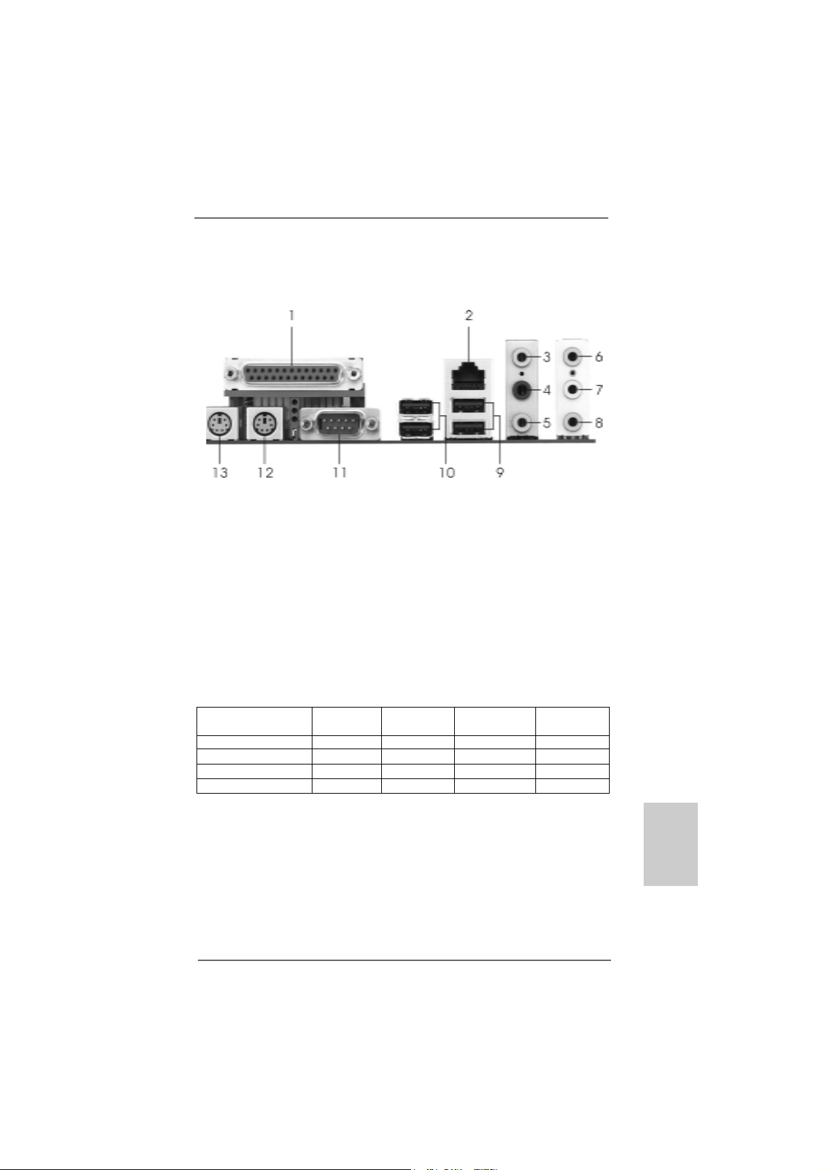
1 Parallel Port 8 Microphone (Pink)
2 RJ-45 Port 9 USB 2.0 Ports (USB01)
3 Side Speaker (Gray) 10 USB 2.0 Ports (USB23)
4 Rear Speaker (Black) 11 Serial Port: COM1
5 Central / Bass (Orange) 12 PS/2 Keyboard Port (Purple)
6 Line In (Light Blue) 13 PS/2 Mouse Port (Green)
*7 Front Speaker (Lime)
* If you use 2-channel spea ker, please connect the speaker’s plug into “Front Speaker Jack”. See
the table below for connection details in accordance with the type of speaker you use.
TABLE for Audio Output Connection
Audio Output Channels Front Speaker Rear Speaker Central / Bass Side Speaker
(No. 7) (No. 4) (No. 5) (No. 3)
2 V -- -- -4 V -- -- V
6V--VV
8 VVVV
ASRock 939Dual-VSTA Motherboard
EnglishEnglish
EnglishEnglish
English
33
3
33
Page 4
1.1.
IntroductionIntroduction
1.
Introduction
1.1.
IntroductionIntroduction
Thank you for purchasing ASRock 939Dual-VSTA motherboard, a reliable
motherboard produced under ASRock’s consistently stringent quality control. It delivers excellent performance with robust design conforming to ASRock’s commitment to quality and endurance.
This Quick Installation Guide contains introduction of the motherboard and step-bystep installation guide. More detailed information of the motherboard can be found in
the user manual presented in the Support CD.
Because the motherboard specifications and the BIOS software might
be updated, the content of this manual will be subject to change without
notice. In case any modifications of this manual occur, the updated
version will be available on ASRock website without further notice. You
may find the latest VGA cards and CPU support lists on ASRock
website as well.
ASRock website http://www.asrock.com
1.11.1
Package ContentsPackage Contents
1.1
Package Contents
1.11.1
Package ContentsPackage Contents
1 x ASRock 939Dual-VSTA Motherboard
(ATX Form Factor: 12.0-in x 9.6-in, 30.5 cm x 24.4 cm)
1 x ASRock 939Dual-VSTA Quick Installation Guide
1 x ASRock 939Dual-VSTA Support CD
1 x Ultra ATA 66/100/133 IDE Ribbon Cable (80-conductor)
1 x 3.5-in Floppy Drive Ribbon Cable
1 x Serial ATA (SATA) Data Cable (Optional)
1 x Serial ATA (SATA) HDD Power Cable (Optional)
1 x ASRock 8CH I/O Shield
English
EnglishEnglish
EnglishEnglish
44
4
44
ASRock 939Dual-VSTA Motherboard
Page 5
1.21.2
SpecificationsSpecifications
1.2
Specifications
1.21.2
SpecificationsSpecifications
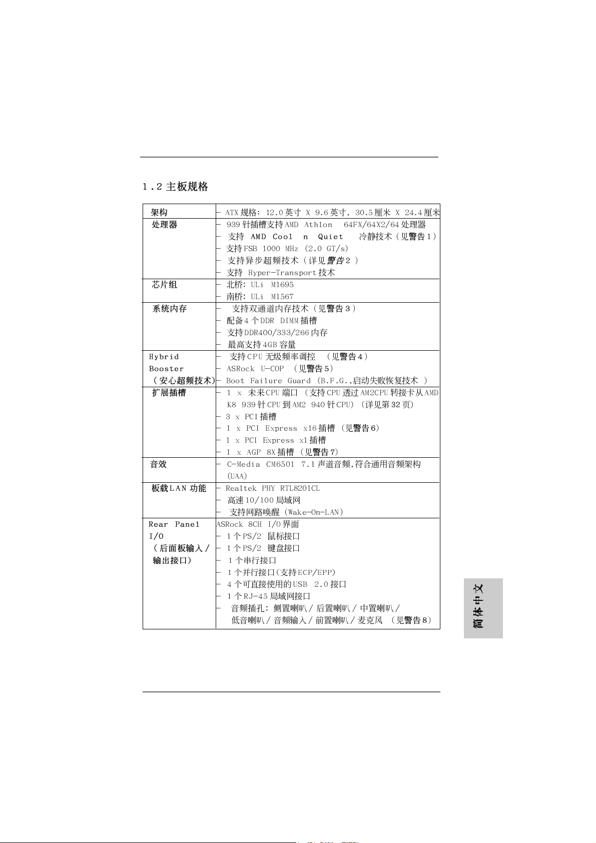
Platform - ATX Form Factor: 12.0-in x 9.6-in, 30.5 cm x 24.4 cm
CPU - Socket 939 for AMD AthlonTM 64FX / 64X2 / 64 Processors
- Supports AMD’s Cool ‘n’ QuietTM Technology
(see CAUTION 1)
- FSB 1000 MHz (2.0 GT/s)
- Supports Untied Overclocking Technology (see CAUTION 2)
- Supports Hyper-Transport Technology
Chipset - Northbridge: ULi® M1695
- Southbridge: ULi® M1567
Memory - Dual Channel DDR Memory T echnology (see CAUTION 3)
- 4 x DDR DIMM slots
- Support DDR400/333/266
- Max. capacity: 4GB
Hybrid Booster - CPU Frequency Stepless Control (see CAUTION 4)
- ASRock U-COP (see CAUTION 5)
- Boot Failure Guard (B.F.G.)
Expansion Slot - 1 x Future CPU Port (Supports CPU upgrade from AMD K8
939-Pin CPU to AM2 940-Pin CPU through AM2CPU Board)
(see page 13 for details)
- 3 x PCI slots
- 1 x PCI Express x16 slot (see CAUTION 6)
- 1 x PCI Express x1 slot
- 1 x AGP 8X slot (see CAUTION 7)
Audio - C-Media CM6501 7.1 channel audio compliant with UAA
architecture
LAN - Realtek PHY RTL8201CL
- Speed: 10/100 Ethernet
- Supports Wake-On-LAN
Rear Panel I/O ASRock 8CH I/O
- 1 x PS/2 Mouse Port
- 1 x PS/2 Keyboard Port
- 1 x Serial Port: COM1
- 1 x Parallel Port (ECP/EPP Support)
- 4 x Ready-to-Use USB 2.0 Ports
- 1 x RJ-45 Port
- Audio Jack: Side Speaker/Rear Speaker/Central / Bass/
Line in/Front Speaker/Microphone (see CAUTION 8)
EnglishEnglish
EnglishEnglish
English
ASRock 939Dual-VSTA Motherboard
55
5
55
Page 6
English
EnglishEnglish
EnglishEnglish
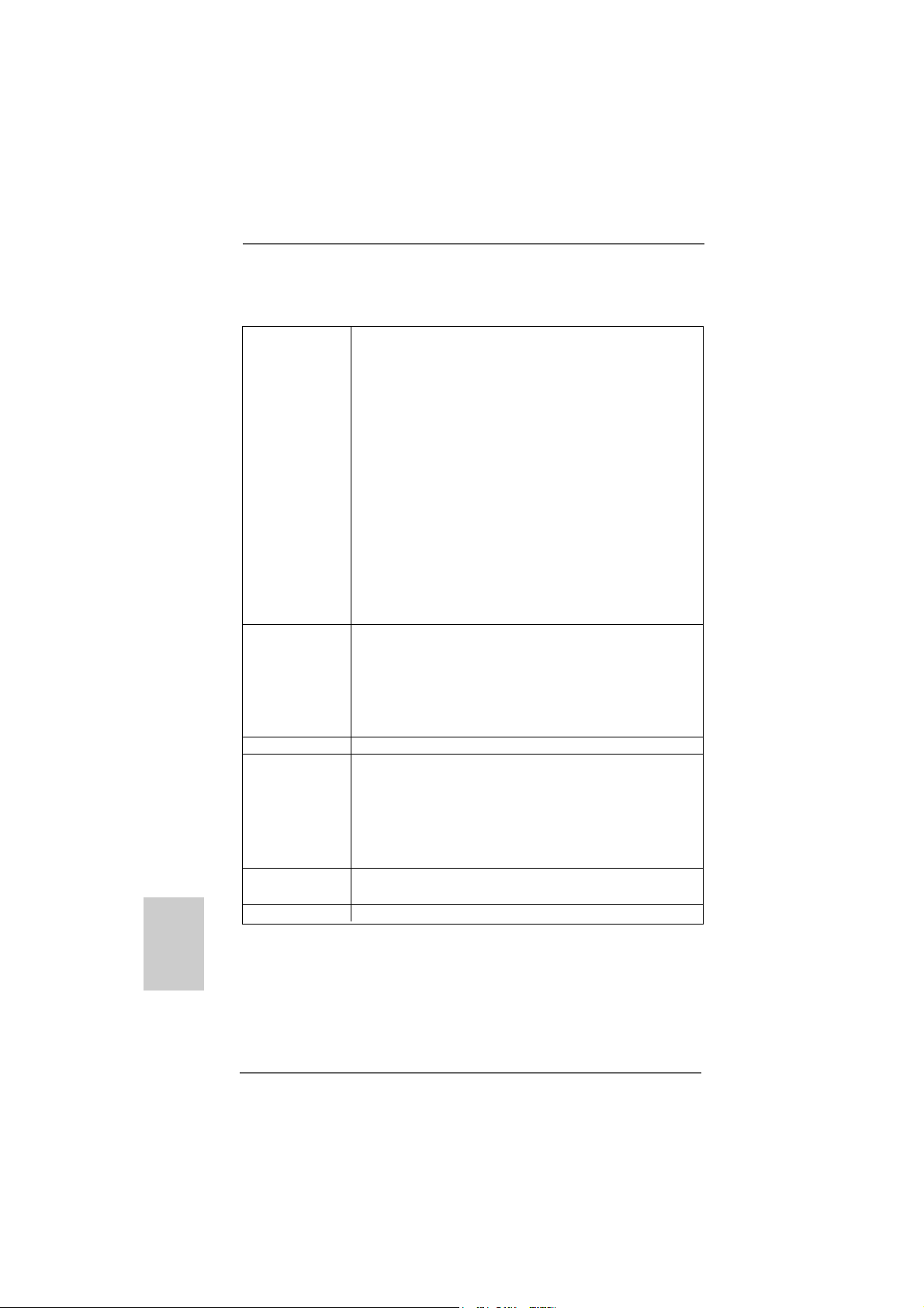
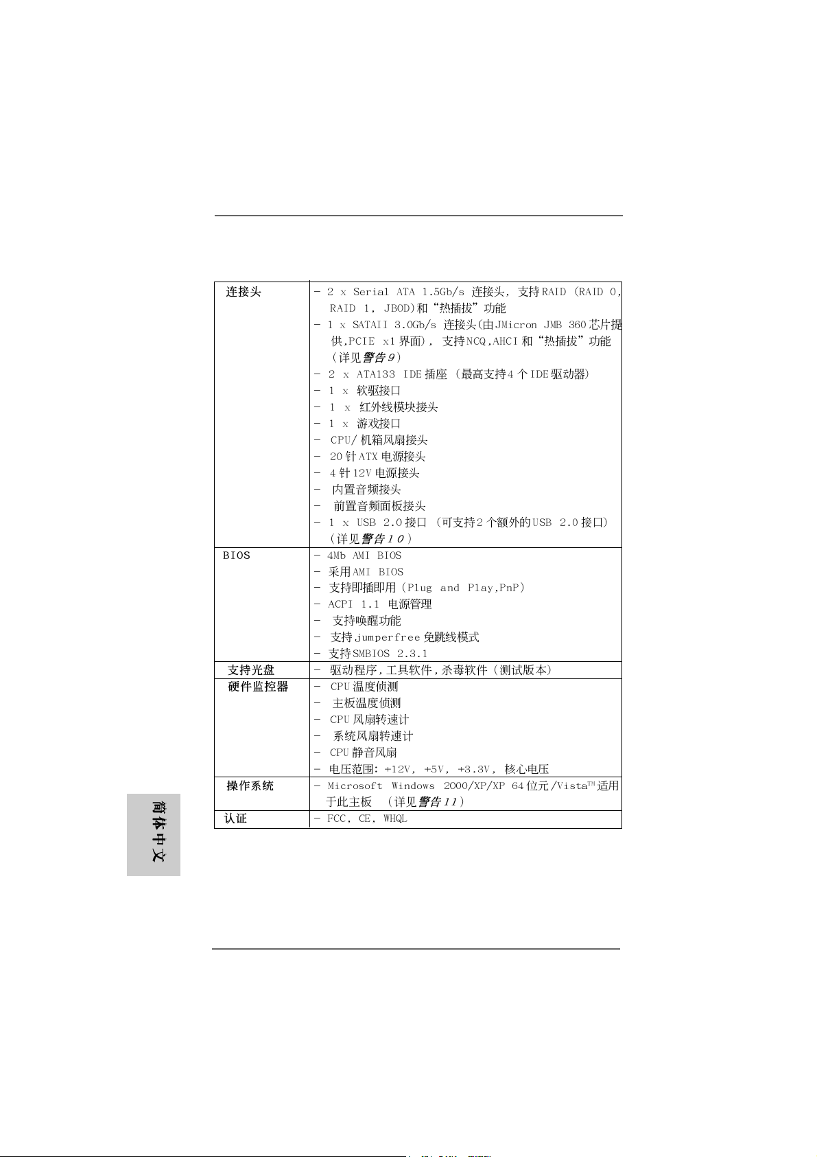
Connector - 2 x Serial ATA 1.5Gb/s connectors, support RAID (RAID 0,
RAID 1, JBOD) and “Hot Plug” functions
- 1 x Serial ATAII 3.0Gb/s connector by JMicron JMB 360
(PCIE x1 interface), supports NCQ, AHCI and “Hot Plug”
functions (see CAUTION 9)
- 2 x ATA133 IDE connectors (support 4 x IDE devices)
- 1 x Floppy connector
- 1 x IR header
- 1 x Game header
- CPU/Chassis FAN connector
- 20 pin ATX power connector
- 4 pin 12V power connector
- CD in header
- Front panel audio connector
- 1 x USB 2.0 headers (supports 2 USB 2.0 ports)
(see CAUTION 10)
BIOS Feature - 4Mb AMI BIOS
- AMI Legal BIOS
- Supports “Plug and Play”
- ACPI 1.1 Compli ance Wa ke Up Events
- Supports jumperfree
- SMBIOS 2.3.1 Support
Support CD - Drivers, Utilities, AntiVirus Software (Trial Version)
Hardware - CPU Temperature Sensing
Monitor - Chassis Temperature Sensing
- CPU Fan Ta chometer
- Chassis Fan Tachometer
- CPU Quiet Fan
- Voltage Monitoring: +12V, +5V, +3.3V, Vcore
OS - Microsoft® Windows® 2000/XP/XP 64-bit/VistaTM compliant
(see CAUTION 11)
Certifications - FCC, CE, Microsoft® WHQL Certificated
66
6
66
ASRock 939Dual-VSTA Motherboard
Page 7

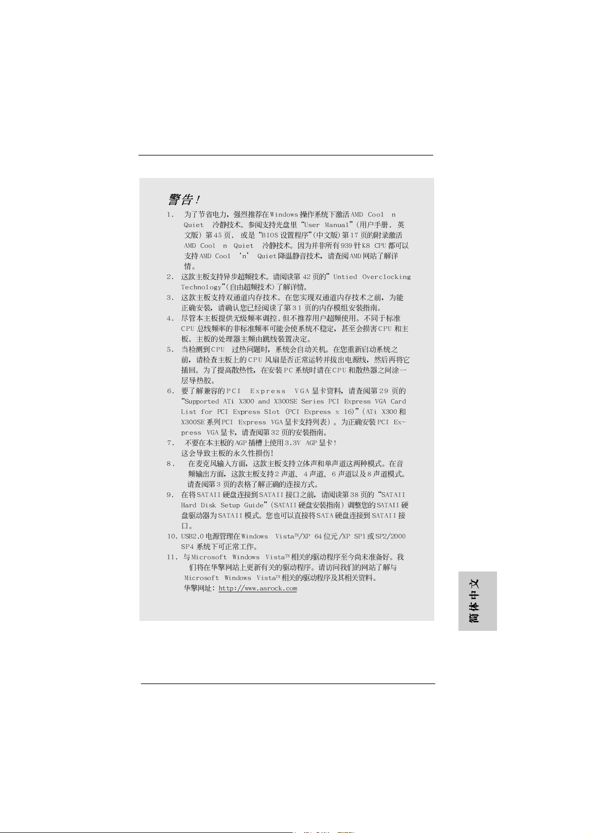
CAUTION!
1. For power-saving’s sake, it is strongly recommended to enable AMD’s Cool ‘n’
QuietTM technology under Windows system. See APPENDIX on page 45 of
“User Manual” in the support CD to enable AMD’s Cool ‘n’ QuietTM technology.
Since not all K8 939-pin CPU can support AMD’s Cool ‘n’ QuietTM technology,
please check AMD’s website for details.
2. This motherboard supports Untied Overclocking Technology. Please read
“Untied Overclocking Technology” on page 23 for details.
3. This motherboard supports Dual Channel Memory Technology. Before you
implement Dual Channel Memory Technology, make sure to read the
installation guide of memory modules on page 11 for proper installation.
4. Although this motherboard offers stepless control, it is not recommended to
perform over-clocking. Frequencies other than the recommended CPU bus
frequencies may cause the instability of the system or damage the CPU.
5. While CPU overheat is detected, the system will automatically shutdown.
Before you resume the system, plea se check if the CPU fa n on the motherboard
functions properly and unplug the power cord, then plug it back again. To
improve heat dissipation, remember to spray thermal grease between the
CPU and the heatsink when you install the PC system.
6. For the information of the compatible PCI Express VGA cards, please
refer to the “Supported ATi X300 and X300SE Series PCI Express VGA
Card List for PCI Express Slot (PCI Express x16)” on page 9. For the
proper installation of PCI Express VGA card, please refer to the installation
guide on page 13.
7. Do NOT use a 3.3V AGP card on the AGP slot of this motherboard!
It may cause permanent damage!
8. For microphone input, this motherboard supports both stereo and mono modes.
For audio output, this motherboard supports 2-channel, 4-channel, 6-channel,
and 8-channel mode s. Please check the table on page 3 for proper connection.
9. Before installing SATAII hard disk to SATAII connector, please read the “SA TAII
Hard Disk Setup Guide” on page 19 to adjust your SATAII hard disk drive to
SATAII mode. You can also connect SATA hard disk to SATAII connector
directly.
10. Power Management for USB 2.0 works fine under Microsoft® Windows
VistaTM / XP 64-bit / XP SP1 or SP2 / 2000 SP4.
11. Microsoft® Windows® VistaTM driver is not ready yet. We will update it to
our website in the future. Please visit our website for Microsoft
Windows® VistaTM driver and related information.
ASRock website http://www.asrock.com
®
®
EnglishEnglish
EnglishEnglish
English
ASRock 939Dual-VSTA Motherboard
77
7
77
Page 8
1.31.3
Minimum Hardware RMinimum Hardware R
1.3
Minimum Hardware R
1.31.3
Minimum Hardware RMinimum Hardware R
TMTM
TM
TMTM
VistaVista
Vista
VistaVista
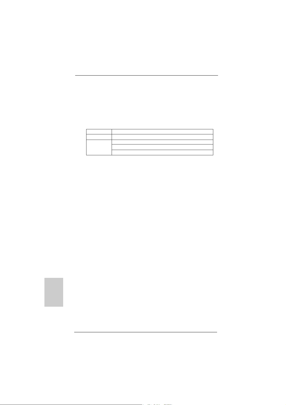
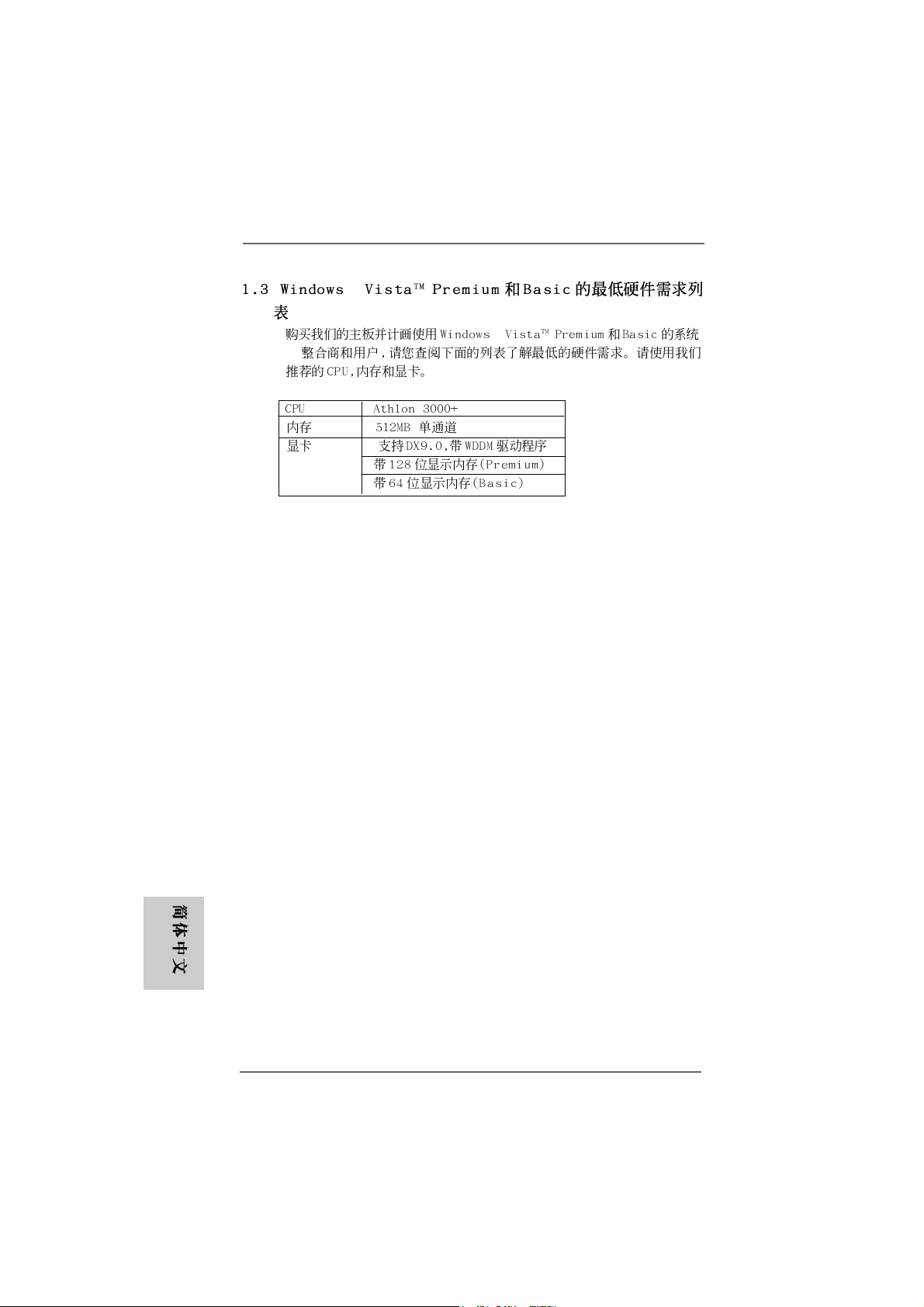
For system integrators and users who purchase this motherboard and
plan to submit Windows® VistaTM Premium and Basic logo, please follow the
below table for minimum hardware requirement. Please adopt the CPU,
memory, and VGA that we suggest.
CPU Athlon 3000+
Memory 512MB Single Channel
VGA DX9.0 with WDDM Driver
Premium and Basic Logo Premium and Basic Logo
Premium and Basic Logo
Premium and Basic Logo Premium and Basic Logo
with 128bit VGA memory (Premium)
with 64bit VGA memory (Basic)
equirement Tequirement T
equirement T
equirement Tequirement T
able for Wable for W
able for W
able for Wable for W
indowsindows
indows
indowsindows
®®
®
®®
English
EnglishEnglish
EnglishEnglish
88
8
88
ASRock 939Dual-VSTA Motherboard
Page 9
1.41.4
SupporSuppor
1.4
Suppor
1.41.4
SupporSuppor
VGA Card List for PCI Express Slot (PCI Express x16)VGA Card List for PCI Express Slot (PCI Express x16)
VGA Card List for PCI Express Slot (PCI Express x16)
VGA Card List for PCI Express Slot (PCI Express x16)VGA Card List for PCI Express Slot (PCI Express x16)
(for Windows® 2000/XP/XP 64-bit/VistaTM)
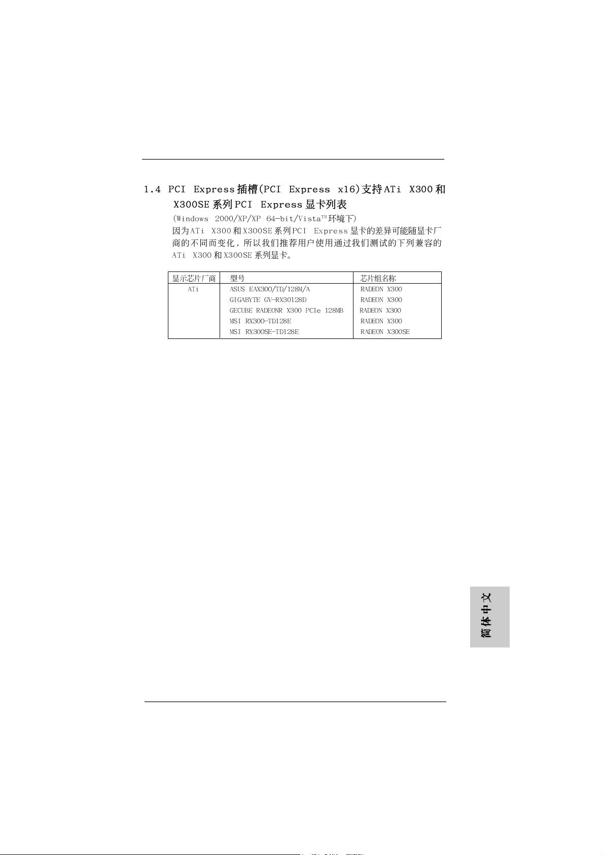
Since the margin of ATi X300 and X300SE series PCI Express VGA cards
may vary with different card vendors, we recommend users to adopt the
compatible ATi X300 and X300SE series cards below which have passed
our lab test.
Graphics Chip Model Name Chipset Name
Vendor
ATi ASUS EAX300/TD/128M/A RADEON X300
ted Ated A
Ti X300 and X300SE Series PCI ExpressTi X300 and X300SE Series PCI Express
ted A
Ti X300 and X300SE Series PCI Express
ted Ated A
Ti X300 and X300SE Series PCI ExpressTi X300 and X300SE Series PCI Express
GIGABYTE GV-RX30128D RADEON X300
GECUBE RADEONR X300 PCIe 128MB RADEON X300
MSI RX300-TD128E RADEON X300
MSI RX300SE-TD128E RADEON X300SE
ASRock 939Dual-VSTA Motherboard
EnglishEnglish
EnglishEnglish
English
99
9
99
Page 10
2.2.
InstallationInstallation
2.
Installation
2.2.
InstallationInstallation
Pre-installation PrecautionsPre-installation Precautions
Pre-installation Precautions
Pre-installation PrecautionsPre-installation Precautions
Take note of the following precautions before you install motherboard components or change any motherboard settings.
1. Unplug the power cord from the wall socket before touching any
component. Failure to do so may cause severe damage to the
motherboard, peripherals, and/or components.
2. To avoid damaging the motherboard components due to static
electricity, NEVER place your motherboard directly on the carpet or the like. Also remember to use a grounded wrist strap or
touch a safety grounded object before you handle components.
3. Hold components by the edges and do not touch the ICs.
4. Whenever you uninstall any component, place it on a
grounded antstatic pad or in the bag that comes with the
component.
5. When placing screws into the screw holes to secure the
motherboard to the chassis, plea se do not over-tighten the screws!
Doing so may damage the motherboard.
2.12.1
CPU InstallationCPU Installation
2.1
CPU Installation
2.12.1
CPU InstallationCPU Installation
Step 1. Unlock the socket by lifting the lever up to a 90° angle.
Step 2. Position the CPU directly above the socket such that the CPU corner with
the golden triangle matches the socket corner with a small triangle.
Step 3. Carefully insert the CPU into the socket until it fits in place.
English
EnglishEnglish
EnglishEnglish
1010
10
1010
The CPU fits only in one correct orientation. DO NOT force the CPU
into the socket to avoid bending of the pins.
Step 4. When the CPU is in place, press it firmly on the socket while you push
down the socket lever to secure the CPU. The lever clicks on the side tab
to indicate that it is locked.
Step 5. Install CPU fan and heatsink. For proper installation, please kindly refer to
the instruction manuals of your CPU fan and heatsink vendors.
ASRock 939Dual-VSTA Motherboard
Page 11
2.2 Installation of Memory Modules (DIMM)2.2 Installation of Memory Modules (DIMM)
2.2 Installation of Memory Modules (DIMM)
2.2 Installation of Memory Modules (DIMM)2.2 Installation of Memory Modules (DIMM)
939Dual-VSTA motherboard provides four 184-pin DDR (Double Data Rate)
DIMM slots, and supports Dual Channel Memory Technology. For dual channel
configuration, you always need to install identical (the same brand, speed,
size and chip-type) DDR DIMM pair in the slots of the same color. In other words,
you have to install identical DDR DIMM pair in Dual Channel A (DDR1 and
DDR2; Blue slots; see p.2 No.7) or identical DDR DIMM pair in Dual Channel B
(DDR3 and DDR4; Black slots; see p.2 No.8), so that Dual Channel Memory
Technology can be activated. This motherboard also allows you to install four
DDR DIMMs for dual channel configuration, and please install identical DDR
DIMMs in all four slots. You may refer to the Dual Channel Memory Configuration
Table below.
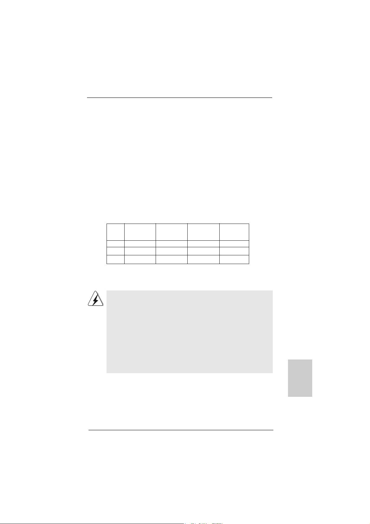
Dual Channel Memory Configurations
DDR1 DDR2 DDR3 DDR4
(Blue Slot) (Blue Slot) (Black Slot) (Black Slot)
(1) Populated Populated - (2) - - Populated Populated
(3)* Populated Populated Populated Populated
* For the configuration (3), please install identical DDR DIMMs in all four slots.
1. If you want to install two memory modules, for optimal compatibility
and reliability, it is recommended to install them in the slots of the
same color. In other words, install them either in the set of blue slots
(DDR1 and DDR2), or in the set of black slots (DDR3 and DDR4).
2. If only one memory module or three memory modules are installed
in the DDR DIMM slots on this motherboard, it is unable to activate
the Dual Channel Memory T e chnology.
3. If a pair of memory modules is NOT installed in the same Dual
Channel, for example, installing a pair of memory modules in DDR1
and DDR3, it is unable to activate the Dual Channel Memory Technology .
ASRock 939Dual-VSTA Motherboard
1111
11
1111
EnglishEnglish
EnglishEnglish
English
Page 12
Installing a DIMMInstalling a DIMM
Installing a DIMM
Installing a DIMMInstalling a DIMM
Please make sure to disconnect power supply before adding or
removing DIMMs or the system components.
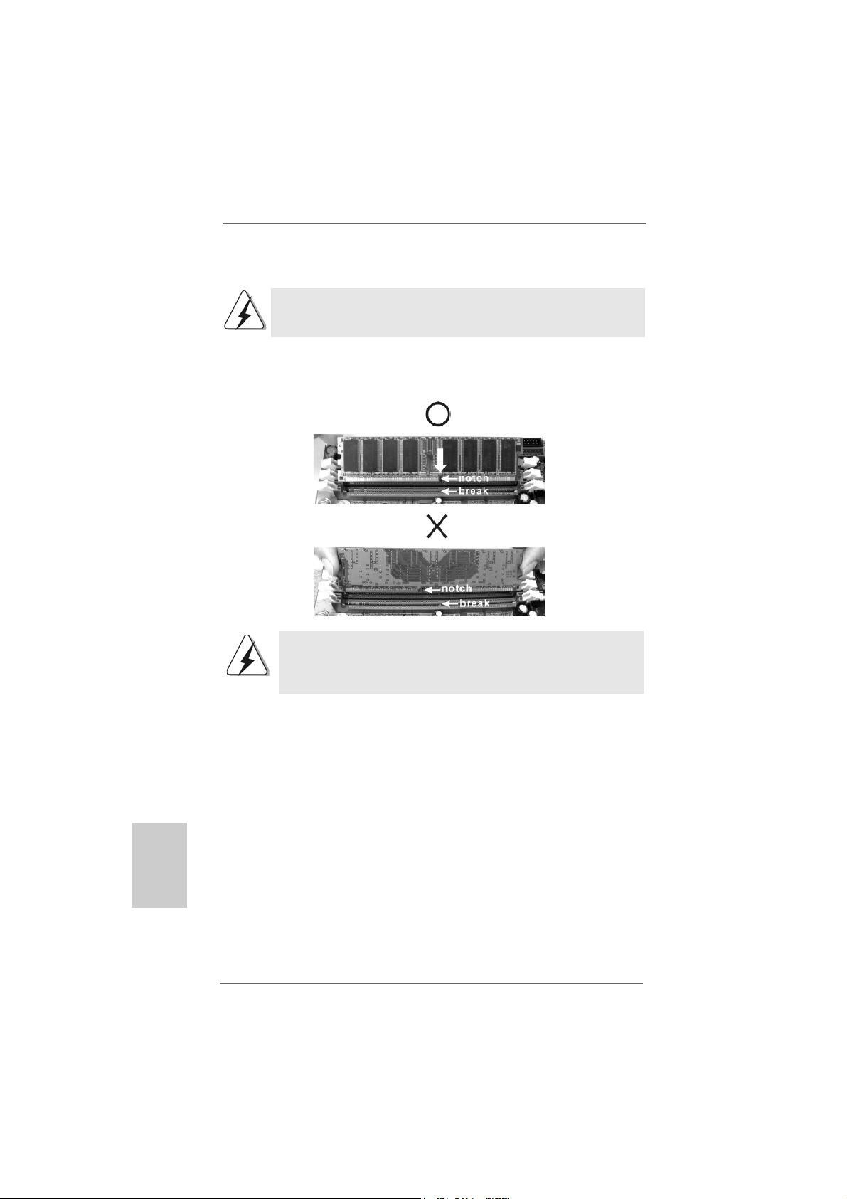
STEP 1: Unlock a DIMM slot by pressing the retaining clips outward.
STEP 2: Align a DIMM on the slot such that the notch on the DIMM matches the
break on the slot.
The DIMM only fits in one correct orientation. It will cause permanent
damage to the motherboard and the DIMM if you force the DIMM into the
slot at incorrect orientation.
English
EnglishEnglish
EnglishEnglish
1212
12
1212
STEP 3: Firmly insert the DIMM into the slot until the retaining clips at both ends
fully snap back in place and the DIMM is properly seated.
ASRock 939Dual-VSTA Motherboard
Page 13
2.32.3
Expansion SlotsExpansion Slots
2.3
Expansion Slots
2.32.3
Expansion SlotsExpansion Slots
(Future CPU Port, PCI Slots, PCIE Slots, and AGP Slot)(Future CPU Port, PCI Slots, PCIE Slots, and AGP Slot)
(Future CPU Port, PCI Slots, PCIE Slots, and AGP Slot)
(Future CPU Port, PCI Slots, PCIE Slots, and AGP Slot)(Future CPU Port, PCI Slots, PCIE Slots, and AGP Slot)
There are 1 Future CPU Port, 3 PCI slots, 2 PCIE slots, and 1 AGP slot on 939DualVSTA motherboard.
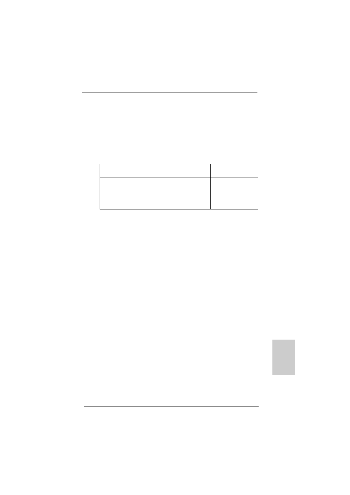
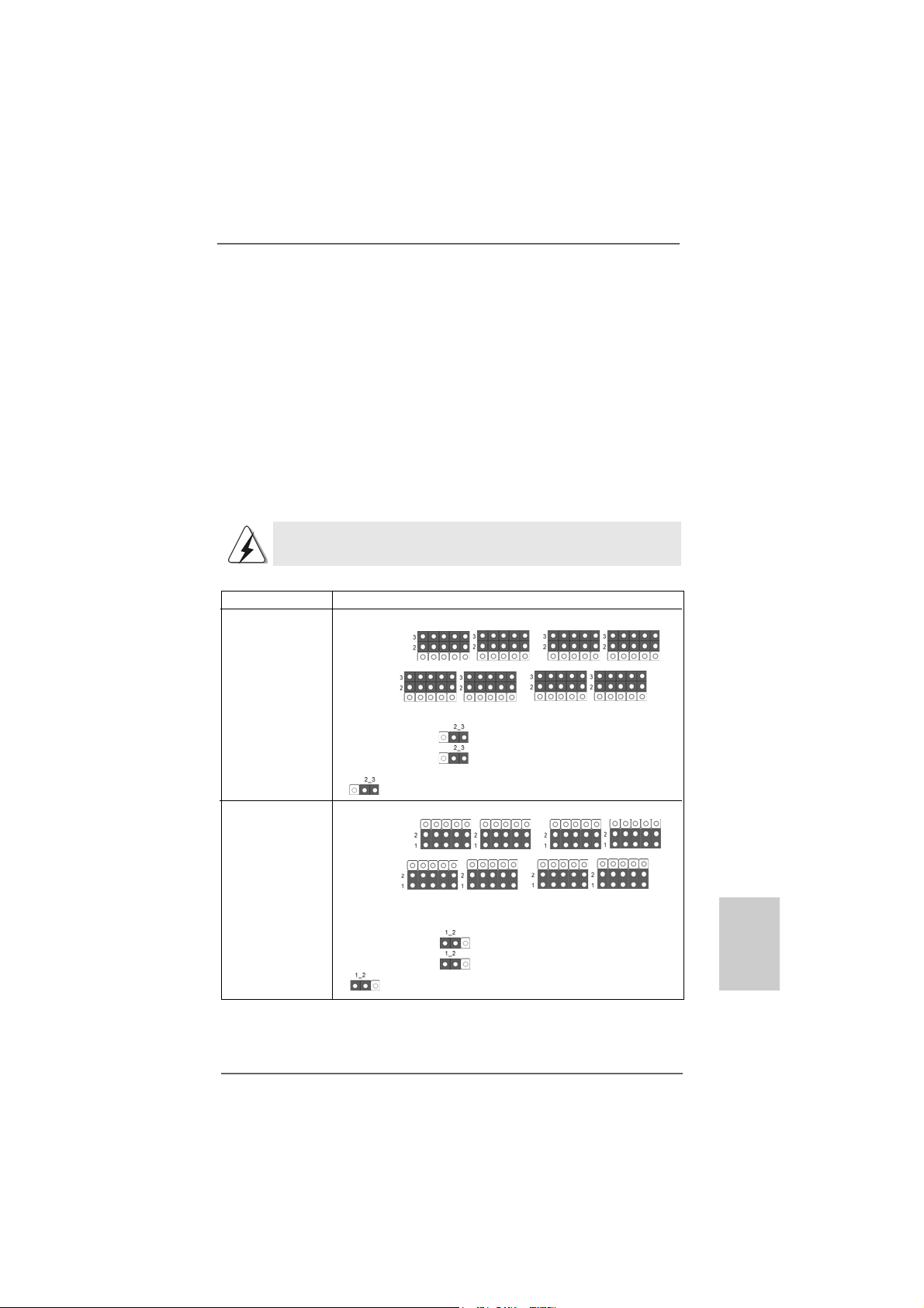
Future CPU Port (Yellow-Colored Port):
Future CPU Port allows you to upgrade your AMD K8 939-Pin CPU to AM2 940-Pin
CPU by installing an add-on ASRock AM2CPU Board into this future CPU Port on
939Dual-VSTA motherboard. Before you upgrade the K8 939-Pin CPU to AM2 940-
Pin CPU, it is necessary to adjust the jumper settings for those required jumpers on
939Dual-VSTA motherboard. Please refer to the table below for the correct jumper
settings.
This yellow-colored Future CPU Port is not an AGP slot! Please do
NOT insert any AGP card into it!
CPU Type Jumper Settings
939-Pin CPU
(Default)
AM2 940-Pin CPU
(Using add-on
ASRock AM2CPU
Board)
J3 J4
J1 J2
J10
J9
J11
J3 J4
J1 J2
J10
J9
J11
J7 J8
J5 J6
J7 J8
J5 J6
ASRock 939Dual-VSTA Motherboard
1313
13
1313
EnglishEnglish
EnglishEnglish
English
Page 14
English
EnglishEnglish
EnglishEnglish
NOTE
When adjusting the jumper settings, you may use the tool, Jumper Cap Remover, to help you
removing the jumper caps more ea sily. This Jumper Cap Remover is bundled in your motherboard
package, and please follow the “Jumper Cap Remover Instruction” to use it properly.
PCI Slots: PCI slots are used to install expansion cards that have the 32-bit PCI
interface.
PCIE Slots: PCIE1 (PCIE x16 slot) is used for PCI Express cards with x16 lane
width graphics cards. For the information of the compatible PCI
Express VGA cards, please refer to the “Supported ATi X300 and
X300SE Series PCI Express VGA Card List for PCI Express Slot (PCI
Express x16)” on page 9.
PCIE2 (PCIE x1 slot) is used for PCI Express cards with x1 lane
width graphics cards, such as Gigabit LAN card, SATA2 card, etc.
AGP slot: The AGP slot is used to in stall a graphics card. The ASRock AGP slot ha s
a special design of clasp that can securely fasten the inserted graphics
card.
Please do NOT use a 3.3V AGP card on the AGP slot of this
motherboard! It may cause permanent da mage! For the voltage infor-
mation of your AGP card, please check with the AGP card vendors.
Installing an expansion cardInstalling an expansion card
Installing an expansion card
Installing an expansion cardInstalling an expansion card
Step 1. Before installing the expansion card, please make sure that the power
supply is switched off or the power cord is unplugged. Please read the
documentation of the expansion card and make necessary hardware
settings for the card before you start the installation.
Step 2. Remove the system unit cover (if your motherboard is already installed in
a chassis).
Step 3. Remove the bracket facing the slot that you intend to use. Keep the
screws for later use.
Step 4. Align the card connector with the slot and press firmly until the card is
completely seated on the slot.
Step 5. Fasten the card to the chassis with screws.
Step 6. Replace the system cover.
1414
14
1414
ASRock 939Dual-VSTA Motherboard
Page 15
2.42.4
Surround Display FeatureSurround Display Feature
2.4
Surround Display Feature
2.42.4
Surround Display FeatureSurround Display Feature
This motherboard supports Surround Display upgrade. With the external add-on
AGP VGA card and PCI Express VGA card, you can easily enjoy the benefits of
Surround Display feature. For the detailed instruction, please refer to the document at the following path in the Support CD: ..\ Surround Display Information
2.52.5
Jumpers SetupJumpers Setup
2.5
Jumpers Setup
2.52.5
Jumpers SetupJumpers Setup
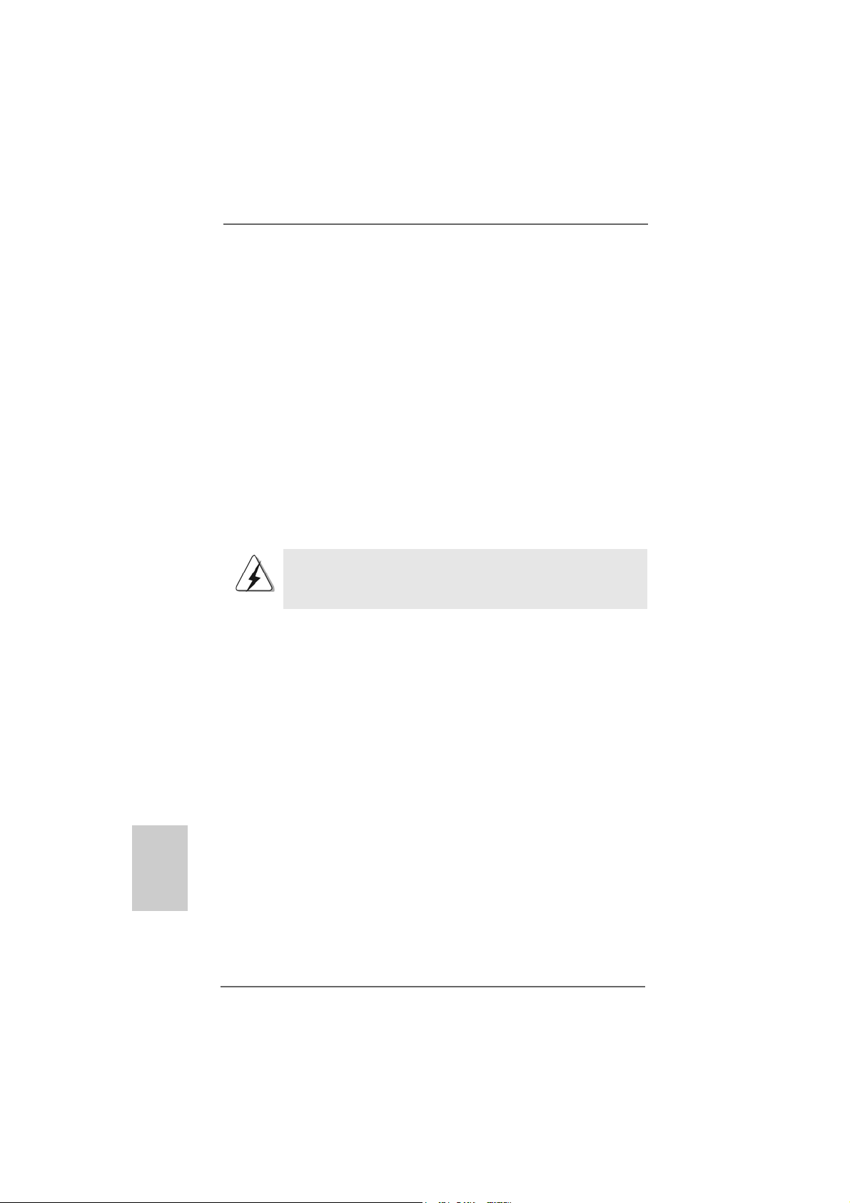
The illustration shows how jumpers are
setup. When the jumper cap is placed on
pins, the jumper is “Short”. If no jumper cap
is placed on pins, the jumper is “Open”. The
illustration shows a 3-pin jumper whose pin1
and pin2 are “Short” when jumper cap is
placed on these 2 pins.
Jumper Setting
PS2_USB_PWR1 Short pin2, pin3 to enable
(see p.2, No. 1) +5VSB (standby) for PS/2 or
Note: To select +5VSB, it requires 2 Amp and higher standby current provided by
power supply.
JR1 JL1 Jumper
(see p.2, No. 27)
Short Open
USB wake up events.
Note: If the jumpers JL1 and JR1 are short, both the front panel and the rear panel
audio connectors can work.
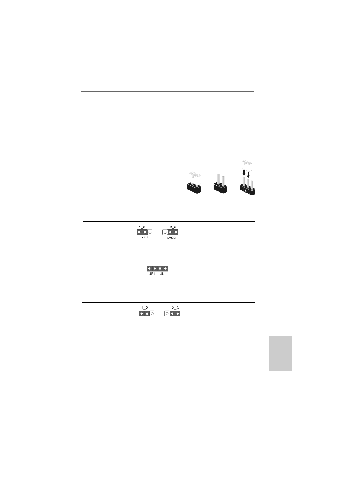
Clear CMOS Jumper
(CLRTC1)
(see p.2, No. 20)
Note: CLRTC1 allows you to clear the data in CMOS. The data in CMOS includes
system setup information such as system password, date, time, and system
setup parameters. To clear and reset the system parameters to default setup,
please turn off the computer and unplug the power cord from the power
supply. After waiting for 15 seconds, use a jumper cap to short pin2 and pin3
on CLRTC1 for 5 seconds. However, please do not clear the CMOS right after
you update the BIOS. If you need to clear the CMOS when you just finish
updating the BIOS, you must boot up the system first, and then shut it down
before you do the clear-CMOS action.
ASRock 939Dual-VSTA Motherboard
Clear CMOSDefault
1515
15
1515
EnglishEnglish
EnglishEnglish
English
Page 16
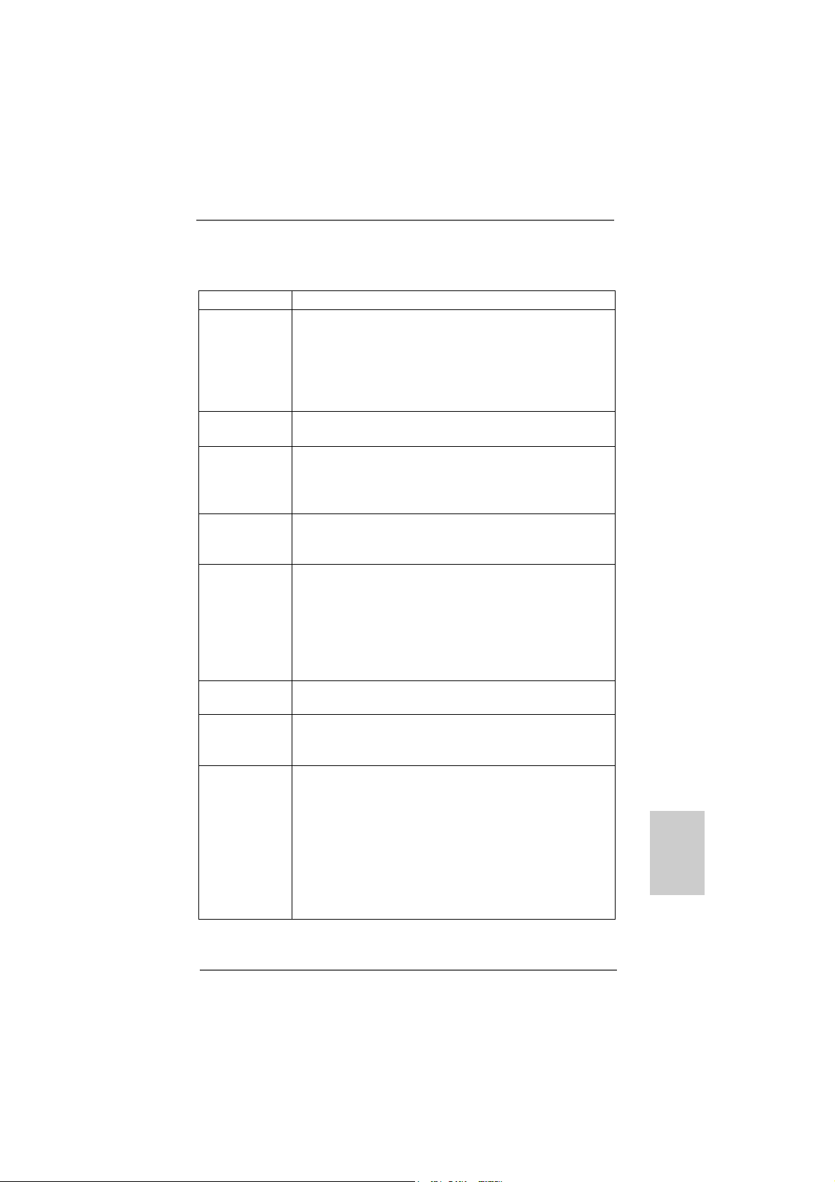
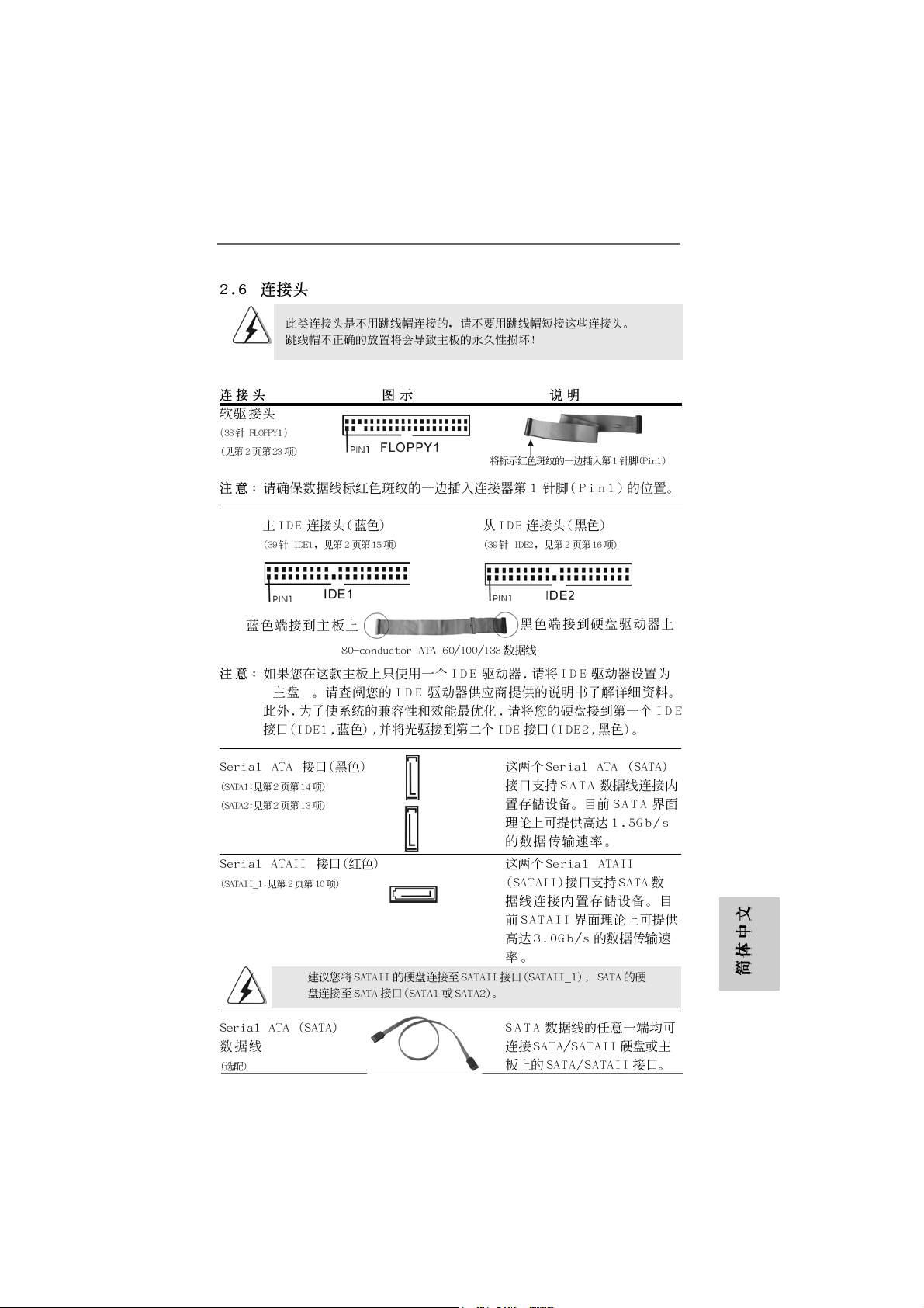
2.6 Onboard Headers and Connectors2.6 Onboard Headers and Connectors
2.6 Onboard Headers and Connectors
2.6 Onboard Headers and Connectors2.6 Onboard Headers and Connectors
Onboard headers and connectors are NOT jumpers. Do NOT place
jumper caps over these headers and connectors. Placing jumper caps
over the headers and connectors will cause permanent damage of the
motherboard!
•
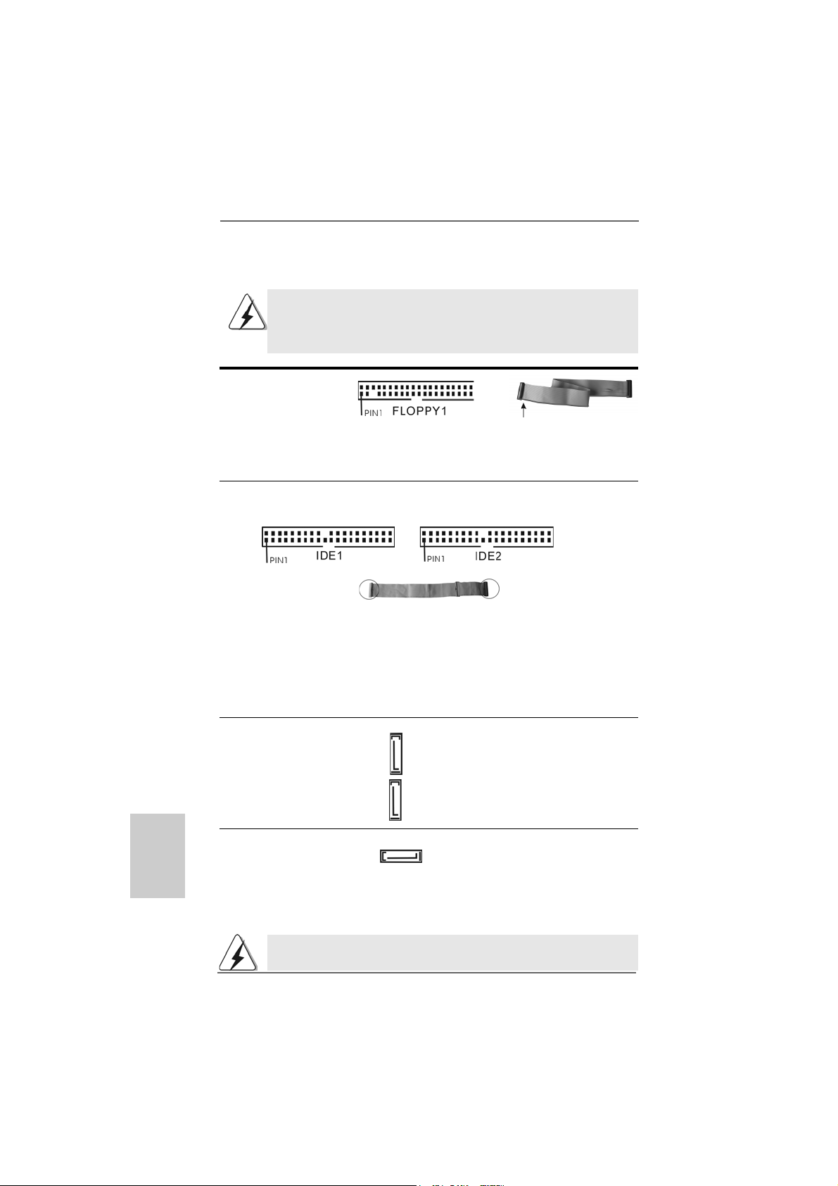
Floppy Connector
(33-pin FLOPPY1)
(see p.2 No. 23)
the red-striped side to Pin1
Note: Make sure the red-striped side of the cable is plugged into Pin1 side of the
connector.
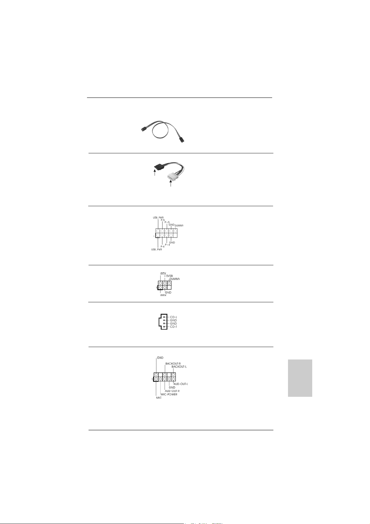
Primary IDE Connector (Blue) Secondary IDE Connector (Black)
(39-pin IDE1, see p.2 No. 15) (39-pin IDE2, see p.2 No. 16)
English
EnglishEnglish
EnglishEnglish
1616
16
1616
connect the blue end
to the motherboard
80-conductor ATA 66/100/133 cable
connect the black end
to the IDE devices
Note: If you use only one IDE device on this motherboard, please set the IDE
device as “Master”. Please refer to the instruction of your IDE device vendor
for the details. Besides, to optimize compatibility and performance, please
connect your hard disk drive to the primary IDE connector (IDE1, blue) and
CD-ROM to the secondary IDE connector (IDE2, black).
Serial ATA Connectors (Black) These two Serial ATA (SATA)
(SAT A1: see p.2 No. 14) connectors support SATA data
(SAT A2: see p.2 No. 13) cables for internal storage
SAT A2
devices. The current SATA
SAT A1
interface allows up to 1.5 Gb/s
data transfer rate.
Serial ATA II Connector (Red) This Serial ATA II (SATA II)
(SAT A II_1: see p.2 No. 10) connector supports SATA
SATA II_1
data cables for internal storage
devices. The current SATAII
interface allows up to 3.0 Gb/s
data transfer rate.
It is recommended to plug SATAII HDD to SATAII connector (SATAII_1) and
connect SATA HDD to SATA connector (SATA1 or SATA2).
ASRock 939Dual-VSTA Motherboard
Page 17
Serial A TA (SATA) Either end of the SA T A data cable
Data Cable can be connected to the SATA /
(Optional) SATAII hard disk or the SATA /
SATAII connector on the
motherboard.
Serial ATA (SATA) Please connect the black end of
Power Cable SATA power cable to the power
(Optional) connector on each drive. Then
connect to the SAT A
HDD power connector
connect to the
power supply
connect the white end of SATA
power cable to the power
connector of the power supply.
USB 2.0 Header Besides four default USB 2.0
(9-pin USB45) ports on the I/O panel, there is
(see p.2 No. 21) one USB 2.0 header on this
motherboard. This USB 2.0
header cansupport two USB
2.0 ports.
Infrared Module Header This header supports an
(5-pin IR1) optional wireless transmitting
(see p.2 No. 24) and receiving infrared module.
Internal Audio Connectors This connector allows you
(4-pin CD1) to receive stereo audio input
(CD1: see p.2 No. 35) from sound sources such as
CD1
a CD-ROM, D VD-ROM, TV
tuner card, or MPEG card.
Front Panel Audio Header This is an interface for front
(8-pin AUDIO1) panel audio cable that allows
(see p.2 No. 26) convenient connection and
control of audio devices.
ASRock 939Dual-VSTA Motherboard
1717
17
1717
EnglishEnglish
EnglishEnglish
English
Page 18
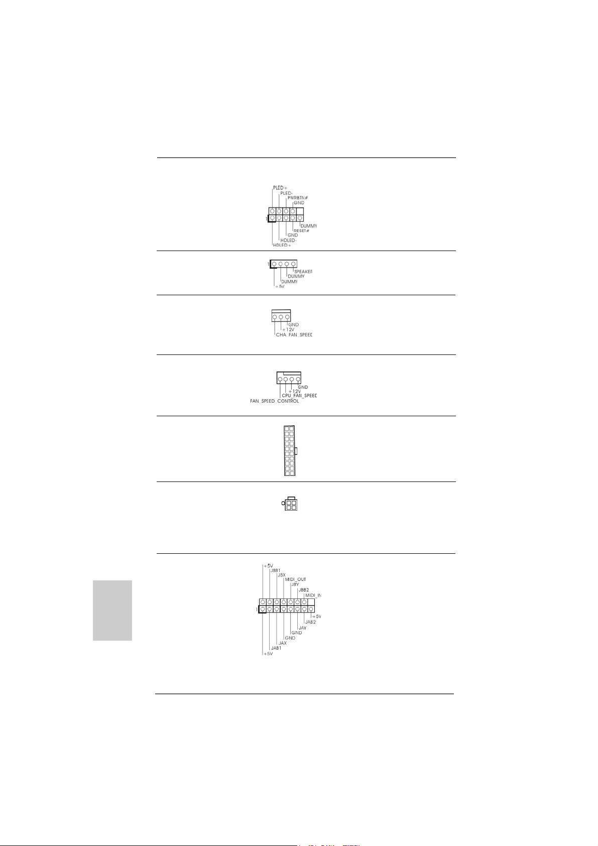
System Panel Header This header accommodates
(9-pin PANEL1) several system front panel
(see p.2 No. 17) functions.
Chassis Speaker Header Please connect the chassis
(4-pin SPEAKER 1) speaker to this header.
(see p.2 No. 18)
Chassis Fan Connector Please connect a chassis fan
(3-pin CHA_FAN1) cable to this connector and
(see p.2 No. 19) match the black wire to the
ground pin.
CPU Fan Connector Please connect the CPU fan
(4-pin CPU_FAN1) cable to this connector and
(see p.2 No. 3) match the black wire to the
ground pin.
ATX Power Connector Please connect an ATX power
(20-pin ATXPW R1) supply to this connector.
(see p.2 No. 2)
English
EnglishEnglish
EnglishEnglish
1818
18
1818
ATX 12V Power Connector Please note that it is necessary
(4-pin A TX12V1) to connect a power supply with
(see p.2 No. 4) ATX 12V plug to this connector.
Failing to do so will cause power
up failure.
Game Port Hea der Connect a Game cable to this
(15-pin GAME1) header if the Game port bracket
(see p.2 No. 25) is installed.
ASRock 939Dual-VSTA Motherboard
Page 19
2.72.7
SASA
TT
2.7
2.72.7
Before installing SATAII hard disk to your computer, please carefully read below
SATAII hard disk setup guide. Some default setting of SATAII hard disks may not
be at SATAII mode, which operate with the best performance. In order to enable
SATAII function, please follow the below instruction with different vendors to
correctly adjust your SATAII hard disk to SATAII mode in advance; otherwise, your
SATAII hard disk may fail to run at SATAII mode.
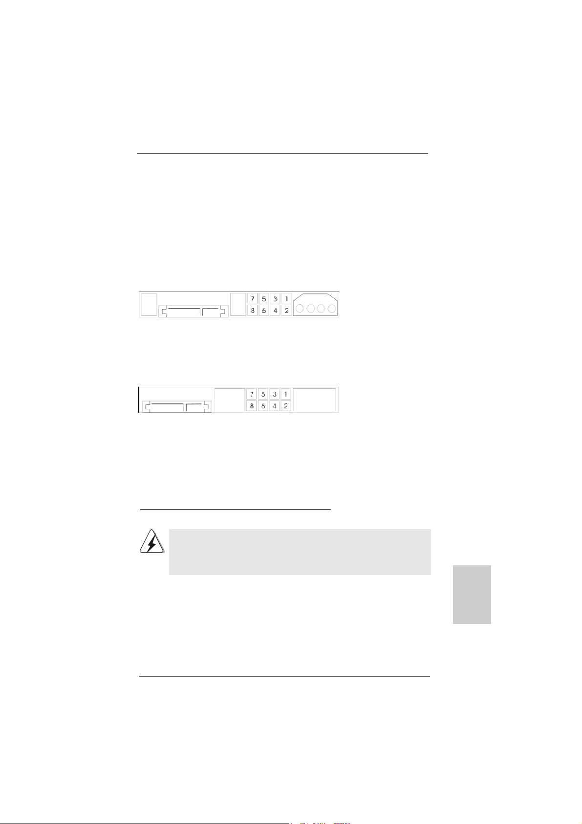
Western Digital
If pin 5 and pin 6 are shorted, SATA 1.5Gb/s will be enabled.
On the other hand, if you want to enable SATAII 3.0Gb/s, please remove the
jumpers from pin 5 and pin 6.
SAMSUNG
If pin 3 and pin 4 are shorted, SATA 1.5Gb/s will be enabled.
On the other hand, if you want to enable SATAII 3.0Gb/s, please remove the
jumpers from pin 3 and pin 4.
AII Hard Disk Setup GuideAII Hard Disk Setup Guide
SA
T
AII Hard Disk Setup Guide
SASA
TT
AII Hard Disk Setup GuideAII Hard Disk Setup Guide
HIT ACHI
Please use the Feature Tool, a DOS-bootable tool, for changing various ATA
features. Please visit HITACHI’s website for details:
http://www.hitachigst.com/hdd/support/download.htm
The above examples are just for your reference. For different SATAII hard
disk products of different vendors, the jumper pin setting methods may not
be the same. Please visit the vendors’ website for the updates.
ASRock 939Dual-VSTA Motherboard
1919
19
1919
EnglishEnglish
EnglishEnglish
English
Page 20
2.82.8
Serial ASerial A
2.8
Serial A
2.82.8
Serial ASerial A
InstallationInstallation
Installation
InstallationInstallation
This motherboard adopts JMicron JMB360 chipset that supports Serial ATAII
(SATAII) hard disk. It also adopts ULi® M1567 south bridge chipset that supports
Serial ATA (SATA) hard disks, and supports RAID functions. You may install SATA /
SATAII hard disks on this motherboard for internal storage devices. This section
will guide you to install the SATA / SATAII hard disks.
STEP 1: Install the SATA / SATAII hard disks into the drive bays of your chassis.
STEP 2: Connect the SATA power cable to the SATA / SATAII hard disk.
STEP 3: Connect one end of the SATA data cable to the motherboard’s SATA /
SATAII connector.
STEP 4: Connect the other end of the SATA data cable to the SATA / SATAII hard
disk.
TT
A (SAA (SA
TT
A (SA
A (SAA (SA
A) / Serial AA) / Serial A
T
A) / Serial A
TT
A) / Serial AA) / Serial A
T
TT
1. If you plan to use RAID 0, RAID 1, or JBOD functions on SATA, SATA
HDDs must be operated in “RAID” mode.
2. “RAID” and “non-RAID” mode are options under “SATA Operation Mode” in
BIOS setup. Please refer to page 35 of “User Manual” in the support CD
for details. They need different drivers during actual operation.
TT
AII (SAAII (SA
T
AII (SA
TT
AII (SAAII (SA
TT
AII) Hard DisksAII) Hard Disks
T
AII) Hard Disks
TT
AII) Hard DisksAII) Hard Disks
English
EnglishEnglish
EnglishEnglish
2020
20
2020
2.9 Hot Plug and Hot Swap F2.9 Hot Plug and Hot Swap F
2.9 Hot Plug and Hot Swap F
2.9 Hot Plug and Hot Swap F2.9 Hot Plug and Hot Swap F
HDDsHDDs
HDDs
HDDsHDDs
939Dual-VSTA motherboard supports Hot Plug and Hot Swap functions for SATA /
SAT AII Device s.
NOTE
What is Hot Plug Function?
If the SATA / SATAII HDDs are NOT set for RAID configuration, it is called
“Hot Plug” for the action to insert and remove the SATA / SATAII HDDs
while the system is still power-on and in working condition.
However, please note that it cannot perform Hot Plug if the OS has been
installed into the SATA / SATAII HDD.
What is Hot Swap Function?
If SATA / SATAII HDDs are built as RAID1 then it is called “Hot Swap” for
the action to insert and remove the SATA / SATAII HDDs while the system
is still power-on and in working condition.
ASRock 939Dual-VSTA Motherboard
unctions for SAunctions for SA
unctions for SA
unctions for SAunctions for SA
TT
A / SAA / SA
T
A / SA
TT
A / SAA / SA
TT
T
TT
AIIAII
AII
AIIAII
Page 21
2.102.10
Driver Installation GuideDriver Installation Guide
2.10
Driver Installation Guide
2.102.10
Driver Installation GuideDriver Installation Guide
To install the drivers to your system, please insert the support CD to your optical
drive first. Then, the drivers compatible to your system can be auto-detected and
listed on the support CD driver page. Please follow the order from up to bottom
side to install those required drivers. Therefore, the drivers you install can work
properly.
2.112.11
Using SAUsing SA
2.11
Using SA
2.112.11
Using SAUsing SA
If you want to install Windows® 2000, Windows® XP or Windows® XP 64-bit OS on
your SATA HDDs with RAID functions, you need to make a SATA driver diskette
before you start the OS installation.
STEP 1: Insert the ASRock Support CD into your optical drive to boot your system.
(Do NOT insert any floppy diskette into the floppy drive at this moment!)
STEP 2: During POST at the beginning of system boot-up, press <F11> key, and
then a window for boot devices selection appears. Please select CDROM as the boot device.
STEP 3: When you see the message on the screen, “Do you want to generate
Serial ATA driver diskette [YN]?”, press <Y>.
STEP 4: Then you will see these messages,
Please insert a floppy diskette into the floppy drive, and press <Y>.
STEP 5: The system will start to format the floppy diskette and copy SATA /
SATAII drivers into the floppy diskette.
TT
A HDDs WA HDDs W
T
A HDDs W
TT
A HDDs WA HDDs W
The installation procedures for Windows® VistaTM are subject to change.
Please insert a diskette into the floppy drive.
WARNING! Formatting the floppy diskette will
lose ALL data in it!
Start to format and copy files [YN]?
ith RAID Fith RAID F
ith RAID F
ith RAID Fith RAID F
unctionsunctions
unctions
unctionsunctions
Once you have the SATA driver diskette ready, you may start to install Windows® 2000
/ Windows® XP / Windows® XP 64-bit on your system directly without setting the RAID
configuration on your system, or you may start to use “RAID Installation Guide” to set
RAID 0 / RAID 1 / JBOD configuration before you install the OS. Before you start to
configure the RAID function, you need to check the installation guide in the Support CD
for proper configuration. Please find the document, “Guide to SATA Hard Disks Installation and RAID Configuration”, at the following path in the Support CD:
.. \ Information \ Manual \ RAID Installation Guide \ English.pdf
ASRock 939Dual-VSTA Motherboard
2121
21
2121
EnglishEnglish
EnglishEnglish
English
Page 22
After making a SATA driver diskette, you can start to install Windows® 2000 / Windows® XP / Windows® XP 64-bit OS on your system. At the beginning of Windows
setup, press F6 to install a third-party SCSI or RAID driver. When prompted, insert a
floppy disk containing the ULi® RAID driver. After reading the floppy disk, the driver
will be presented. Select the driver to install according to the mode you choose and
the OS you install.
2.122.12
Using SAUsing SA
2.12
Using SA
2.122.12
Using SAUsing SA
If you want to install Windows® 2000, Windows® XP or Windows® XP 64-bit OS on
your SATA HDDs operating in non-RAID mode, you don’t need to make a SATA driver
diskette before OS installation. Please follow the below procedures.
STEP 1: Enter “SATA Operation Mode” in BIOS setup to set the option from [RAID]
to [non-RAID].
STEP2: Start Windows® 2000, Windows® XP or Windows® XP 64-bit OS
installation.
2.132.13
Using SAUsing SA
2.13
Using SA
2.132.13
Using SAUsing SA
If you want to install Windows® 2000, Windows® XP or Windows® XP 64-bit OS on
your SATAII HDDs operating in IDE mode, you don’t need to make a SATAII driver
diskette or set up BIOS before OS installation.
TT
A HDDs WA HDDs W
T
A HDDs W
TT
A HDDs WA HDDs W
The installation procedures for Windows® VistaTM are subject to change.
TT
AII HDDs in “IDE” ModeAII HDDs in “IDE” Mode
T
AII HDDs in “IDE” Mode
TT
AII HDDs in “IDE” ModeAII HDDs in “IDE” Mode
The installation procedures for Windows® VistaTM are subject to change.
ithout RAID Fithout RAID F
ithout RAID F
ithout RAID Fithout RAID F
unctionsunctions
unctions
unctionsunctions
®
English
EnglishEnglish
EnglishEnglish
2222
22
2222
2.142.14
Using SAUsing SA
2.14
Using SA
2.142.14
Using SAUsing SA
If you want to install Windows® 2000, Windows® XP or Windows® XP 64-bit OS on
your SATAII HDDs in SATA mode, you need to make a SATAII driver diskette before
you start the OS installation. Please follow the below procedures.
STEP 1: Please see the “Readme.txt” in SATAII driver directory on the support CD
for the files needed to copy to the diskette. Then make a SATAII driver
diskette.
STEP 2: Enter “SATAII Operation Mode” in BIOS setup to set the option from [IDE]
to [SATA].
STEP 3: Start Windows® 2000, Windows® XP or Windows® XP 64-bit OS
installation. At the beginning of Windows® setup, press F6 to install a
TT
AII HDDs in “SAAII HDDs in “SA
T
AII HDDs in “SA
TT
AII HDDs in “SAAII HDDs in “SA
The installation procedures for Windows® VistaTM are subject to change.
ASRock 939Dual-VSTA Motherboard
TT
A” ModeA” Mode
T
A” Mode
TT
A” ModeA” Mode
Page 23

third-party SCSI or RAID driver. When prompted, insert a floppy disk
containing the JMicron® RAID driver. After reading the floppy disk, the
driver will be presented. Select the driver to install according to the mode
you choose and the OS you install.
2.152.15
Untied Overclocking TUntied Overclocking T
2.15
Untied Overclocking T
2.152.15
Untied Overclocking TUntied Overclocking T
This motherboard supports Untied Overclocking Technology, which means during
overclocking, FSB enjoys better margin due to fixed AGP / PCI / PCIE buses. Before
you enable Untied Overclocking function, please enter “Overclock Mode” option of
BIOS setup to set the selection from [Auto] to [CPU, PCIE, Async.]. Therefore, CPU
FSB is untied during overclocking, but AGP / PCI / PCIE buses are in the fixed mode so
that FSB can operate under a more stable overclocking environment.
3. BIOS Information3. BIOS Information
3. BIOS Information
3. BIOS Information3. BIOS Information
The Flash Memory on the motherboard stores BIOS Setup Utility. When you start up
the computer, please press <F2> during the Power-On-Self-Test (POST) to enter
BIOS Setup utility; otherwise, POST continues with its test routines. If you wish to
enter BIOS Setup after POST, please restart the system by pressing <Ctl> + <Alt> +
<Delete>, or pressing the reset button on the system chassis.
The BIOS Setup program is designed to be user-friendly. It is a menu-driven program,
which allows you to scroll through its various sub-menus and to select among the
predetermined choices. For the detailed information about BIOS Setup, please refer
to the User Manual (PDF file) contained in the Support CD.
echnologyechnology
echnology
echnologyechnology
4. Software Suppor4. Software Suppor
4. Software Suppor
4. Software Suppor4. Software Suppor
This motherboard supports various Microsoft® Windows® operating systems: 2000 /
XP / XP 64-bit / VistaTM. The Support CD that came with the motherboard contains
necessary drivers and useful utilities that will enhance motherboard features.
To begin using the Support CD, insert the CD into your CD-ROM drive. It will display
the Main Menu automatically if “AUTORUN” is enabled in your computer. If the Main
Menu does not appear automatically, locate and double-click on the file “ASSETUP.
EXE” from the “BIN” folder in the Support CD to display the menus.
ASRock 939Dual-VSTA Motherboard
t CD informationt CD information
t CD information
t CD informationt CD information
2323
23
2323
EnglishEnglish
EnglishEnglish
English
Page 24
2424
24
2424
ASRock 939Dual-VSTA Motherboard
Page 25
™
‘ ’ ™
®
®
ASRock 939Dual-VSTA Motherboard
2525
25
2525
Page 26
2626
26
2626
®
®
ASRock 939Dual-VSTA Motherboard
Page 27
™
‘ ’ ™
‘ ’
®
®
®
®
®
ASRock 939Dual-VSTA Motherboard
2727
27
2727
Page 28
®
®
2828
28
2828
ASRock 939Dual-VSTA Motherboard
Page 29
®
ASRock 939Dual-VSTA Motherboard
2929
29
2929
Page 30
3030
30
3030
ASRock 939Dual-VSTA Motherboard
Page 31

DDR1 DDR2 DDR3 DDR4
( )( )( )( )
(1) - (2) - -
(3)
ASRock 939Dual-VSTA Motherboard
3131
31
3131
Page 32

3232
32
3232
ASRock 939Dual-VSTA Motherboard
Page 33

J3 J4
J7 J8
J1 J2
J11
J1 J2
J11
J5 J6
J10
J9
J3 J4
J5 J6
J10
J9
“
”
ASRock 939Dual-VSTA Motherboard
3333
33
3333
Page 34

3434
34
3434
ASRock 939Dual-VSTA Motherboard
Page 35
“ ”
SAT A2
SAT A1
SATA II_1
ASRock 939Dual-VSTA Motherboard
3535
35
3535
Page 36

3636
36
3636
CD1
ASRock 939Dual-VSTA Motherboard
Page 37

ASRock 939Dual-VSTA Motherboard
3737
37
3737
Page 38

3838
38
3838
ASRock 939Dual-VSTA Motherboard
Page 39

®
ASRock 939Dual-VSTA Motherboard
3939
39
3939
Page 40

®
®
® ® ®
®
®
4040
40
4040
.. \ Information \ Manual \ RAID Installation Guide \ Chinese.pdf
® ®
® ®
®
ASRock 939Dual-VSTA Motherboard
Page 41

®
®
®
®
®
®
®
®
®
®
®
®
®
®
®
®
®
®
®
®
ASRock 939Dual-VSTA Motherboard
4141
41
4141
Page 42

4242
42
4242
® ®
ASRock 939Dual-VSTA Motherboard
Page 43
1. Einführung1. Einführung
1. Einführung
1. Einführung1. Einführung
Wir danken Ihnen für den Kauf des ASRock 939Dual-VSTA Motherboard, ein
zuverlässiges Produkt, welches unter den ständigen, strengen Qualitätskontrollen
von ASRock gefertigt wurde. Es bietet Ihnen exzellente Leistung und robustes Design,
gemäß der Verpflichtung von ASRock zu Qualität und Halbarkeit.
Diese Schnellinstallationsanleitung führt in das Motherboard und die schrittweise
Installation ein. Details über das Motherboard finden Sie in der Bedienungsanleitung
auf der Support-CD.
Da sich Motherboard-Spezifikationen und BIOS-Software verändern können,
kann der Inhalt dieses Handbuches ebenfalls jederzeit geändert werden. Für
den Fall, dass sich Änderungen an diesem Handbuch ergeben, wird eine neue
Version auf der ASRock-Website, ohne weitere Ankündigung, verfügbar sein.
Die neuesten Grafikkarten und unterstützten CPUs sind auch auf der
ASRock-Website aufgelistet.
ASRock-Website: http://www.asrock.com
1.1 Kartoninhalt
ASRock 939Dual-VSTA Motherboard
(ATX-Formfaktor: 30.5 cm x 24.4 cm; 12.0 Zoll x 9.6 Zoll)
ASRock 939Dual-VSTA Schnellinstallationsanleitung
ASRock 939Dual-VSTA Support-CD
Ein 80-adriges Ultra-ATA 66/100/133 IDE-Flachbandk abel
Ein Flachbandkabel für ein 3,5-Zoll-Diskettenlaufwerk
Ein Seriell-ATA- (SATA) Datenkabel (Option)
Ein Seriell-ATA (SATA) Festplattennetzkabel (Option)
Ein ASRock 8CH I/O Shield
ASRock 939Dual-VSTA Motherboard
4343
43
4343
DeutschDeutsch
DeutschDeutsch
Deutsch
Page 44
Deutsch
DeutschDeutsch
DeutschDeutsch
1.21.2
SpezifikationenSpezifikationen
1.2
Spezifikationen
1.21.2
SpezifikationenSpezifikationen
Plattform - ATX-Formfaktor: 30.5 cm x 24.4 cm; 12.0 Zoll x 9.6 Zoll
CPU - 939-pol. Sockel, unterstützt AMD AthlonTM 64FX / 64X2 / 64
Prozessoren
- Unterstützt Cool ‘n’ Quiet™-Technologie von AMD
(siehe VORSICHT 1)
- FSB 1000 MHz (2.0 GT/s)
- Unterstützt Untied-Übertaktungstechnologie
(siehe VORSICHT 2)
- Unterstützt Hyper-Transport-Technologie
Chipsatz - Northbridge: ULi® M1695
- Southbridge: ULi® M1567
Speicher - Unterstützung von Dual-Kanal-Speichertechnologie
(siehe VORSICHT 3)
- 4 x Steckplätze für DDR
- Unterstützt DDR400/333/266
- Max. 4GB
Hybrid Booster - Schrittloser CPU-Frequenz-Kontrolle (siehe VORSICHT 4)
- ASRock U-COP (siehe VORSICHT 5)
- Boot Failure Guard (B.F.G. – Systemstartfehlerschutz)
Erweiterungs- - 1 x Future CPU-Port (unterstützt CPU-Aufrüstung von 939 steckplätze poliger AMD K8- CPU auf 940-polige AM2-CPU über AM2CPU-
Board) (Details auf Seite 51)
- 3 x PCI-Steckplätze
- 1 x PCI Express x16-Steckplätze (siehe VORSICHT 6)
- 1 x PCI Express x1-Steckplätze
- 1 x AGP 8X-Steckplätze (siehe VORSICHT 7)
Audio - C-Media CM6501 7,1-Kanal-Audio-kompatibel, mit UAA-
Architektur
LAN - Realtek PHY RTL8201CL
- Speed: 10/100 Ethernet
- Unterstützt Wake-On-LAN
E/A-Anschlüsse ASRock 8CH I/O
an der - 1 x PS/2-Mausanschluss
Rückseite - 1 x PS/2-Tastaturanschluss
- 1 x Serieller port: COM 1
- 1 x Paralleler port: Unterstützung für ECP / EPP
- 4 x Standard-USB 2.0-Anschlüsse
- 1 x RJ-45 port
4444
44
4444
ASRock 939Dual-VSTA Motherboard
Page 45

- Audiobuchse: Lautsprecher seitlich / Lautsprecher hinten
/ Mitte/Bass / Audioeingang/ Lautsprecher vorne / Mikrofon
(siehe VORSICHT 8)
Anschlüsse - 2 x Serial ATA-Anschlüsse, unterstützt bis 1.5 Gb/s
Datenübertragungsrate, unterstützt RAID (RAID 0, RAID 1,
JBOD) und “Hot Plug” Funktionen
- 1 x SATAII-Anschluss, 3,0 GB/s, von JMicron JMB 360 (PCIE
x1-Schnittstelle), unterstützt NCQ, AHCI und „Hot Plug“ Funktionen (siehe VORSICHT 9)
- 2 x ATA133 IDE-Anschlüsse (Unterstützt bis 4 IDE-Geräte)
- 1 x FDD-Anschlüsse
- 1 x Infrarot-Modul-Header
- 1 x Game-Anschluss
- CPU/Gehäuse-Lüfteranschluss
- 20-pin ATX-Netz-Header
- 4-pin anschluss für 12V-ATX-Netzteil
- Interne Audio-Anschlüsse
- Anschluss für Audio auf der Gehäusevorderseite
- 1 x USB 2.0-Anschlüsse (Unterstützung 2
zusätzlicher USB 2.0-Anschlüsse) (siehe VORSICHT 10)
BIOS - 4Mb AMI BIOS
- AMI legal BIOS mit Unterstützung für “Plug and Play”
- ACPI 1.1-Weckfunktionen
- JumperFree-Modus
- SMBIOS 2.3.1
Support-CD - Treiber, Dienstprogramme, Antivirussoftware
(Probeversion)
Hardware Monitor - Überwachung der CPU-Temperatur
- Motherboardtemperaturerkennung
- Drehzahlmessung für CPU-Lüfter
- Drehzahlmessung für Gehäuselüfter
- CPU-Lüftergeräuschdämpfung
- Spannungsüberwachung: +12V, +5V, +3.3V, Vcore
Betriebssysteme - Unterstützt Microsoft® Windows® 2000 / XP / XP 64-Bit /
VistaTM (siehe VORSICHT 11)
Zertifizierungen - FCC, CE, WHQL
DeutschDeutsch
DeutschDeutsch
Deutsch
ASRock 939Dual-VSTA Motherboard
4545
45
4545
Page 46

Deutsch
DeutschDeutsch
DeutschDeutsch
4646
46
4646
VORSICHT!
1. Um Energie zu sparen, wird dringendst empfohlen, die Cool ‘n’ Quiet™Technologie von AMD im Windows-System zu aktivieren. Siehe ANHANG
auf Seite 45 des “Handbuchs” auf der Support-CD für Hinweise zur
Aktivierung der Cool ‘n’ Quiet™-Technologie von AMD. Da nicht alle 939
poligen K8 CPUs AMDs Cool’n’Quiet Technologie unterstützen, rufen Sie
Details bitte von den AMD Internetseiten ab.
2. Dieses Motherboard unterstützt die Untied-Übertaktungstechnologie.
Unter “Entkoppelte Übertaktungstechnologie” auf Seite 62 finden Sie
detaillierte Informationen.
3. Dieses Motherboard unterstützt Dual-Kanal-Speichertechnologie. Vor
Implementierung der Dual-Kanal-Speichertechnologie müssen Sie die
Installationsanleitung für die Speichermodule auf Seite 49 zwecks
richtiger Installation gelesen haben.
4. Obwohl dieses Motherboard stufenlose Steuerung bietet, wird
Overclocking nicht empfohlen. Frequenzen, die von den empfohlenen
CPU-Busfrequenzen abweichen, können Instabilität des Systems
verursachen oder die CPU beschädigen.
5. Wird eine Überhitzung der CPU registriert, führt das System einen
automatischen Shutdown durch. Bevor Sie das System neu starten, prüfen
Sie bitte, ob der CPU-Lüfter am Motherboard richtig funktioniert, und
stecken Sie bitte den Stromkabelstecker aus und dann wieder ein. Um die
Wärmeableitung zu verbessern, bitte nicht vergessen, etwas
Wärmeleitpaste zwischen CPU und Kühl körper zu sprühen.
6. Informationen über kompatible PCI Express VGA-Karten finden Sie in
der “Liste unterstützter ATi X300 und X300SE Reihe PCI Express VGAKarten” auf den Seiten 9. (Nur Englisch) Die richtige Installation der PCI
Express-Grafikkarte ist in der Installationsanleitung auf Seite 51
angegeben.
7. Stecken Sie KEINE 3,3V AGP-Karte in den AGP-Steckplatz dieses
Motherboards! Permanente Beschädigung könnte die Folge sein!
8. For microphone input, this motherboard supports both stereo and mono modes.
For audio output, this motherboard supports 2-channel, 4-channel, 6-channel,
and 8-channel mode s. Please check the table on page 3 for proper connection.
9. Bevor Sie eine SATA II Festplatte mit dem SATA II Anschluss verbinden,
lesen Sie bitte die “Anleitung zur SATA II Festplatteneinrichtung“ auf
Seite 58, um Ihre SATA II Festplatte in den SATA II Modus umzuschalten.
SATA-Festplatten können Sie auch direkt mit dem SATA II-Anschluss
verbinden.
10. Das Power Management für USB 2.0 arbeitet unter Microsoft® Windows
VistaTM / XP 64-Bit / XP SP1 oder SP2/2000 SP4 einwandfrei.
11. Der Treiber für Microsoft® Windows® VistaTM ist noch nicht einsatzbereit.
Sie können ihn bald von unserer Internetseite abrufen. Auf unserer
Internetseite finden Sie Angaben zum Microsoft® Windows® Vista
Treiber sowie weitere Informationen.
ASRock-Internetseite: http://www.asrock.com
ASRock 939Dual-VSTA Motherboard
®
TM
Page 47

1.31.3
Minimale Hardwarevorausetzungen für WindowsMinimale Hardwarevorausetzungen für Windows
1.3
Minimale Hardwarevorausetzungen für Windows
1.31.3
Minimale Hardwarevorausetzungen für WindowsMinimale Hardwarevorausetzungen für Windows
TMTM
TM
TMTM
VistaVista
Vista
VistaVista
Systemintegratoren und Anwender unseres Motherboards, die ihre
Rechner auf die Vergabe des Windows® VistaTM Premium und Basic Logos vorbereiten möchten, finden die minimalen
Hardwarevoraussetzungen in der folgenden Tabelle. Bitte nutzen Sie die
von uns empfohlenen Prozessoren, Speicherbausteine und VGA Komponenten.
CPU Athlon 3000+
Speicher 512 MB, Single Channel
VGA DX9.0 mit WDDM-Treiber
Premium und Basic Logo Premium und Basic Logo
Premium und Basic Logo
Premium und Basic Logo Premium und Basic Logo
mit 128 Bit-VGA-Speicher (Pre mium)
mit 64 Bit-VGA-Speicher (Basic)
®
ASRock 939Dual-VSTA Motherboard
4747
47
4747
DeutschDeutsch
DeutschDeutsch
Deutsch
Page 48

2. Installation2. Installation
2. Installation
2. Installation2. Installation
Sicherheitshinweise vor der MontageSicherheitshinweise vor der Montage
Sicherheitshinweise vor der Montage
Sicherheitshinweise vor der MontageSicherheitshinweise vor der Montage
Bitte nehmen Sie die folgende Sicherheitshinweise zur Kenntnis,
bevor Sie das Motherboard einbauen oder Veränderungen an den
Einstellungen vornehmen.
1. Trennen Sie das System vom Stromnetz, bevor Sie eine
Systemkomponente berühren, da es sonst zu schweren Schäden am
Motherboard oder den sonstigen internen, bzw. externen Komponenten
kommen kann.
2. Um Schäden aufgrund von statischer Elektrizität zu vermeiden, das
Motherboard NIEMALS auf einen Teppich o.ä.legen. Denken Sie außerem
daran, immer ein geerdetes Armband zu tragen oder ein geerdetes Objekt
aus Metall zu berühren, bevor Sie mit Systemkomponenten hantieren.
3. Halten Sie Komponenten immer an den Rändern und vermeiden Sie
Berührungen mit den ICs.
4. Wenn Sie Komponenten ausbauen, legen Sie sie immer auf eine
antistatische Unterlage, oder zurück in die Tüte, mit der die Komponente
geliefert wurde.
5. Wenn Sie das Motherboard mit den Schrauben an dem Computergehäuse
befestigen, überziehen Sie bitte die Schrauben nicht! Das Motherboard
kann sonst beschädigt werden.
2.1 CPU Installation2.1 CPU Installation
2.1 CPU Installation
2.1 CPU Installation2.1 CPU Installation
Schritt 1: Öffnen Sie den CPU-Sockel, indem sie den Hebel leicht zur Seite und
dann nach oben ziehen, auf einen Winkel von 90°.
Schritt 2: Positionieren Sie die CPU genau so über dem Sockel, dass sich die
Ecke der CPU mit dem goldenen Dre ieck exakt über der Ecke des
Sockels befindet, die mit einem kleinen Dreieck gekennzeichnet ist.
Schritt 3: Drücken Sie die CPU vorsichtig in den Sockel.
Deutsch
DeutschDeutsch
DeutschDeutsch
4848
48
4848
Die CPU sollte problemlos in den Sockel passen. Drücken Sie die CPU
nicht mit Gewalt in den Sockel, damit sich die Pins nicht verbiegen.
Überprüfen Sie die Ausrichtung und suchen nach verbogenen Pins,
sollte die CPU nicht in den Sockel passen.
Schritt 4: Wenn die CPU korrekt i m Sockel sitzt, leicht mit de m Finger
draufdrücken und gleichzeitig den Hebel nach unten drücken, bis er
hörbar einrastet.
Schritt 5: Installieren Sie einen aktiven CPU-Kühler, der die gesamte Fläche der
CPU abdeckt und eine ausreichende Wärmeableitung für den von
Ihnen verwendeten CPU-Typ bietet. Weitere Hinweise finden Sie der
Installationsanleitung für Ihren CPU-Kühler.
ASRock 939Dual-VSTA Motherboard
Page 49

2.2 Installation der Speichermodule (DIMM)2.2 Installation der Speichermodule (DIMM)
2.2 Installation der Speichermodule (DIMM)
2.2 Installation der Speichermodule (DIMM)2.2 Installation der Speichermodule (DIMM)
Die Motherboards 939Dual-VSTA bieten vier 184-pol. DDR (Double Data Rate)
DIMM-Steckplätze und unterstützen die Dual-Kanal-Speichertechnologie. Für die
Dual-Kanalkonfiguration dürfen Sie nur identische (gleiche Marke,
Geschwindigkeit, Größe und gleicher Chiptyp) DDR DIMM-Paare in den
Steckplätzen gleicher Farbe installieren. Mit anderen Worten, sie müssen ein
identisches DDR DIMM-Paar im Dual-Kanal A (DDR1 und DDR2; blaue Steckplätze,
siehe Seite 2 Nr. 7) oder ein identisches DDR DIMM-Paar im Dual-Kanal B (DDR3
und DDR4; schwarze Steckplätze, siehe Seite 2 Nr. 8) installieren, damit die DualKanal-Speichertechnologie aktiviert werden kann. Auf diesem Motherboard
können Sie auch vier DDR DIMMs für eine Dual-Kanalkonfiguration installieren. Auf
diesem Motherboard können Sie auch vier DD R DIMM-Module für eine DualKanalkonfiguration installieren, wobei Sie bitte in allen vier Steckplätzen identische
DDR DIMM-Module installieren. Beziehen Sie sich da b ei auf die nachstehende
Konfigurationstabelle für Dual-Kanalspeicher.
Dual-Kanal-Speicherkonfigurationen
DDR1 DDR2 DDR3 DDR4
(blaue Steckplätze) (blaue Steckplätze) (schwarze Steckplätze) (schwarze Steckplätze)
(1) Bestückt Bestückt - (2 ) - - Bestückt Bestückt
(3) Bestückt Bestückt Bestückt Bestückt
* Für Konfiguration (3) installieren Sie bitte identische DDR DIMMs in allen vier
Steckplätzen.
1. Wenn Sie zwei Speichermodule installieren möchten, verwenden Sie
dazu für optimale Kompatibilität und Stabilität Steckplätze gleicher
Farbe. Installieren Sie die beiden Speichermodule also entweder in
den blauen Steckplätzen (DDR 1 und DDR 2) oder den schwarzen
Steckplätzen (DDR3 und DDR 4).
2. Wenn nur ein Speichermodul oder drei Spe ichermodule in den DDR
DIMM-Steckplätzen auf diesem Motherboard installiert sind, kann es
die Dual-Kanal-Speichertechnologie nicht aktivieren.
3. Ist ein Speichermodulpaar NICHT im gleichen “Dual-Kanal” installiert,
z.B. ein Speichermodulpaar wird in DDR1 und DDR3 installiert, kann
es die Dual-Kanal-Speichertechnologie nicht aktivieren.
ASRock 939Dual-VSTA Motherboard
4949
49
4949
DeutschDeutsch
DeutschDeutsch
Deutsch
Page 50

Einsetzen eines DIMM-ModulsEinsetzen eines DIMM-Moduls
Einsetzen eines DIMM-Moduls
Einsetzen eines DIMM-ModulsEinsetzen eines DIMM-Moduls
Achten Sie darauf, das Netzteil abzustecken, bevor Sie DIMMs oder
Systemkomponenten hinzufügen oder entfernen.
Schritt 1: Öffnen Sie einen DIMM-Slot, indem Sie die seitlichen Clips nach außen
drücken.
Schritt 2: Richten Sie das DIMM-Modul so über de m Slot aus, dass da s Modul mit
der Kerbe in den Slot passt.
Die DIMM-Module passen nur richtig herum eingelegt in die
Steckplätze. Falls Sie versuchen, die DIMM-Module mit Gewalt falsch
herum in die Steckplätze zu zwingen, führt dies zu dauerhaften
Schäden am Mainboard und am DIMM-Modul.
Deutsch
DeutschDeutsch
DeutschDeutsch
5050
50
5050
Schritt 3: Drücken Sie die DIMM-Module fest in die Steckplätze, so dass die
Halteklammern an beiden Enden des Moduls einschnappen und das
DIMM-Modul fest an Ort und Stelle sitzt.
ASRock 939Dual-VSTA Motherboard
Page 51

2.32.3
Erweiterungssteckplätze Erweiterungssteckplätze
2.3
Erweiterungssteckplätze
2.32.3
Erweiterungssteckplätze Erweiterungssteckplätze
, PCIE-Steckplätze und A, PCIE-Steckplätze und A
, PCIE-Steckplätze und A
, PCIE-Steckplätze und A, PCIE-Steckplätze und A
(Future CPU Port, PCI-Steckplätze(Future CPU Port, PCI-Steckplätze
(Future CPU Port, PCI-Steckplätze
(Future CPU Port, PCI-Steckplätze(Future CPU Port, PCI-Steckplätze
GPGP
-Steckplatz)-Steckplatz)
GP
-Steckplatz)
GPGP
-Steckplatz)-Steckplatz)
Es gibt einen Futur CPU Port, 3 PCI-Steckplätze, 2 PCIE-Steckplätze und 1 AGPSteckplätze am 939Dual-VSTA Motherboard.
Futur CPU Port (gelb gekennzeichneter Anschluss):
Der Port für zukünftige CPUs ermöglicht Ihnen die Aufrüstung Ihrer K8 939-poligen
AMD-CPU auf eine AM2 940-polige AMD-CPU. Dies erreichen Sie durch die
Installation eines zusätzlichen ASRock AM2CPU-Boards in diesem Port für
zukünftige CPUs am 939Dual-VSTA-Motherboard. Bevor Sie die K8 939-polige
auf die AM2 940-polige CPU aufrüsten, müssen Sie die Steckbrückeneinstellungen
(„Jumper“) der zutreffenden Steckbrücken am 939Dual-VSTA-Motherboard
ändern. Die richtigen Steckbrückeneinstellungen finden Sie in der nachstehenden
Tabelle.
Dieser gelb gekennzeichnete Futur CPU Port ist kein AGPSteckplatz! Stecken Sie keine AGP-Karte hier hinein!
CPU Typ
939-pol. CPU
(Standard)
AM2 940-pol.
CPU
(Mit einem Add-on
ASRock AM2CPU
Board)
Jumpereinstellungen
J3 J4 J7 J8
J1 J2
J10
J9
J11
J3 J4 J7 J8
J1 J2
J10
J9
J11
J5 J6
J5 J6
ASRock 939Dual-VSTA Motherboard
5151
51
5151
DeutschDeutsch
DeutschDeutsch
Deutsch
Page 52

HIN WEIS
Wenn Sie die Jumpereinstellungen vornehmen, können Sie das Werkzeug
Jumpersteckbrücken-Entferner verwenden, um das Entfernen der Jumpersteckbrücken zu
erleichtern. Der Jumper Cap Remover ist Ihrem Motherboard-Paket beigelegt. Beachten Sie
bitte die Gebrauchsanleitung des “Jumpersteckbrücken-Entferner“, um ihn richtig zu
verwenden.
PCI-Slots: PCI-Slots werden zur Installation von Erweiterungskarten mit dem 32bit
PCI-Interface genutzt.
PCI Express-Slots:
PCIE1 (PCIE x16-Steckplatz) wird für PCI ExpressGrafikkarten mit x16-Busbreite verwendet. Für weitere
Informationen bezüglich kompatibler PCI Express VGA-Karten, siehe
„Liste unterstützter ATi X300 und X300SE Reihe PCI Express VGAKarten für PCI Express (PCI Express x16) Steckplatz” auf Seite 9.
PCIE2 (PCIE x1-Steckplatz) wird für PCI Express-Grafikkarten mit
x1-Busbreite verwendet wie Gigabit LAN-Karten, SATA2Karten, usw. eingesetzt.
AGP-Slot: Der AGP-Steckplatz dient zur Installation einer Grafikkarte. Der
ASRock AGP-Steckplatz hat speziell entwickelte Klammern, die die
eingefügte Grafikkarte sicher festhalten.
Stecken Sie KEINE 3,3V AGP-Karte in den AGP-Steckplatz dieses
Motherboards! Permanente Beschädigung könnte die Folge sein
Erkundigen Sie sich beim Verkäufer der Grafikkarte nach den
Spannungsdaten für Ihre Grafikkarte.
Deutsch
DeutschDeutsch
DeutschDeutsch
5252
52
5252
Einbau einer ErweiterungskarteEinbau einer Erweiterungskarte
Einbau einer Erweiterungskarte
Einbau einer ErweiterungskarteEinbau einer Erweiterungskarte
Schritt 1: Bevor Sie die Erweiterungskarte installieren, vergewissern Sie sich,
dass das Netzteil ausgeschaltet und das Netzkabel abgezogen ist. Bitte
lesen Sie die Dokumentation zur Erweiterungskarte und nehmen Sie
nötige Hardware-Einstellungen für die Karte vor, ehe Sie mit der
Installation beginnen.
Schritt 2: Entfernen Sie das Abdeckungsblech (Slotblende) von dem
Gehäuseschacht (Slot) , den Sie nutzen möchten und behalten die
Schraube für den Einbau der Karte.
Schritt 3: Richten Sie die Karte über dem Slot aus und drücken Sie sie ohne
Gewalt hinein, bis sie den Steckplatz korrekt ausfüllt.
Schritt 4: Befestigen Sie die Karte mit der Schraube aus Schritt 2.
ASRock 939Dual-VSTA Motherboard
Page 53

2.4 “Surround Display”2.4 “Surround Display”
2.4 “Surround Display”
2.4 “Surround Display”2.4 “Surround Display”
Dieses Motherboard unterstützt Surround Display-Aufrüstung. Mit einer externen,
zusätzlichen AGP- und PCI Express-VGA-Karte können Sie die Vorteile der
Surround Display-Funktion problemlos genießen. Für detaillierte Informationen,
siehe folgendes Dokument auf beiliegender Support-CD:
..\ Surround Display Information
2.5 Einstellung der Jumper2.5 Einstellung der Jumper
2.5 Einstellung der Jumper
2.5 Einstellung der Jumper2.5 Einstellung der Jumper
Die Abbildung verdeutlicht, wie Jumper
gesetzt werden. Werden Pins durch
Jumperkappen verdeckt, ist der Jumper
“gebrückt”. Werden keine Pins durch
Jumperkappen verdeckt, ist der Jumper
“offen”. Die Abbildung zeigt einen 3-Pin
Jumper dessen Pin1 und Pin2 “gebrückt” sind,
bzw. es befindet sich eine Jumper-Kappe
auf diesen beiden Pins.
Jumper Einstellun
PS2_USB_PWR1 Überbrücken Sie Pin2, Pin3, um
(siehe S.2, Punkt 1) +5VSB (Standby) zu setzen
Hinweis: Um +5VSB nutzen zu können, muss das Netzteil auf dieser Leitung 2A
oder mehr leisten können.
Gebrückt Offen
und die PS/2 oder USBWeckfunktionen zu aktivieren.
JR1 JL1-Jumper
(siehe S.2, Punkt 27)
Hinweis: Wenn die JR1- und JL1- Jumper verbunden sind, können die
Audioanschlüsse an dem Frontfeld sowie an der Rückwand arbeiten.
CMOS löschen Jumper
(CLRTC1)
(siehe S.2 - Nr. 20)
Hinweis: CLRTC1 erlaubt Ihnen das Löschen der CMOS-Daten. Diese beinhalten
das System-Passwort, Datum, Zeit und die verschiedenen BIOSParameter. Um die Systemparameter zu löschen und auf die
Werkseinstellung zurückzusetzen, schalten Sie bitte den Computer ab
und entfernen das Stromkabel. Benutzen Sie eine Jumperkappe, um die
Pin 2 und Pin 3 an CLRTC1 für 5 Sekunden kurzzuschließen. Bitte
ASRock 939Dual-VSTA Motherboard
DefaultEinstellung
CMOS
löschen
5353
53
5353
DeutschDeutsch
DeutschDeutsch
Deutsch
Page 54

vergessen Sie nicht, den Jumper wieder zu entfernen, nachdem das
CMOS gelöscht wurde. Bitte vergessen Sie nicht, den Jumper wieder zu
entfernen, nachdem das CMOS gelöscht wurde. Wenn Sie den CMOSInhalt gleich nach dem Aktualisieren des BIOS löschen müssen, müssen
Sie zuerst das System starten und dann wieder ausschalten, bevor Sie
den CMOS-Inhalt löschen.
2.6 Anschlüsse2.6 Anschlüsse
2.6 Anschlüsse
2.6 Anschlüsse2.6 Anschlüsse
Anschlussleisten sind KEINE Jumper. Setzen Sie KEINE Jumperkappen
auf die Pins der Anschlussleisten. Wenn Sie die Jumperkappen auf die
Anschlüsse setzen, wird das Motherboard permanent beschädigt!
Anschluss Beschreibung
Anschluss für das
Floppy-Laufwerk
(33-Pin FLOPPY1)
(siehe S.2, Punkt 23)
Hinweis: Achten Sie darauf, dass die rotgestreifte Seite des Kabel mit der Stift 1-
Seite des Anschlusses verbunden wird.
Primärer IDE-Anschluss (blau) Sekundärer IDE-Anschluss (schwarz)
(39-pin IDE1, siehe S.2, Punkt 15) (39-pin IDE2, siehe S.2, Punkt 16)
die rotgestreifte Seite auf Stift 1
Deutsch
DeutschDeutsch
DeutschDeutsch
5454
54
5454
Blauer Anschluss Schwarzer Anschluss
zum Motherboard zur Festplatte
80-adriges A T A 66/100/133-Kabel
Hinweis: Wenn Sie auf diesem Motherboard nur ein IDE-Gerät einsetzen, richten Sie
das IDE-Gerät als “M a ster” ein. Details entnehmen Sie bitte den Anweisungen
Ihres IDE-Gerätehändlers. Zur Optimierung der Kompatibilität und Leistung
verbinden Sie die Festplatte mit dem primären IDE-Anschluss (IDE1, blau)
und das CD-ROM mit dem sekundären IDE-Anschluss (IDE2, schwarz).
ASRock 939Dual-VSTA Motherboard
Page 55

Seriell-ATA-Anschlüsse (Schwarzes) Diese beiden Serial ATA-
(SAT A1: siehe S.2, Punkt 14) (SATA-)Verbínder
(SAT A2: siehe S.2, Punkt 13) unterstützten SATA-Datenkabel
SAT A2
für interne
SAT A1
Massen spe ichergeräte. Die
aktuelle SATA-Schnittstelle
ermöglicht eine
Datenübertragungsrate bis
1,5 Gb/s.
Seriell-ATAII-Anschlüsse (Rot) Diese beiden Serial ATAII-
(SAT AII_1: siehe S.2 - No. 10) (SATAII-)Verbínder
unterstützten SATA-
SATA II_1
Datenkabel für interne
Massen spe ichergeräte. Die
aktuelle SATAII-Schnittstelle
ermöglicht eine
Datenübertragungsrate bis
3,0 Gb/s.
Es wird empfohlen, die SATAII-Festplatte mit dem SATAII-Anschluss (SATAII_1)
und die SATA-Festplatte mit dem SA TA-Anschluss (SA TA1, SATA2) zu verbinden.
Serial A TA- (SATA-) Sie können beide Enden des
Datenkabel SATA-Datenkabels entweder
(Option) mit der SATA / SATAII-
Festplatte oder dem SATA /
SATAII-Anschluss am
Mainboard verbinden.
Serial A TA- (SATA-) Verbinden Sie das schwarze
Stromversorgungskabel Ende des SATA-Netzkabels mit
(Option) dem Netzan schluss am
SATA-HDD-Stromanschluss
Verbindung zum
Verbindung zum
Netzteil
Laufwerk. Verbinden Sie dann
das weiße Ende des SATAStromversorgungskabels mit
dem Stromanschluss des
Netzteils.
ASRock 939Dual-VSTA Motherboard
5555
55
5555
DeutschDeutsch
DeutschDeutsch
Deutsch
Page 56

USB 2.0-Header Zusätzlich zu den vier
(9-pol. USB45) üblichen USB 2.0-Ports an den
(siehe S.2 - Nr. 21) I/O-Anschlüssen befinden sich
ein USB 2.0-Anschlussleisten
am Motherboard. Pro USB 2.0 Anschlussleiste werden zwei
USB 2.0-Ports unterstützt.
Infrarot-Modul-Header Dieser Header unterstützt ein
(5-pin IR1) optionales, drahtloses Sende-
(siehe S.2 - No. 24) und Empfangs-Infrarotmodul.
Interne Audio-Anschlüsse Diese ermöglichen Ihnen Stereo-
(4-Pin CD1) Signalquellen, wie z. B. CD-ROM,
(CD1: siehe S.2, Punkt 35) DVD-ROM, TV-T uner oder
CD1
MPEG-Karten mit Ihrem System
zu verbinden.
Anschluss für Audio auf Dieses Interface zu einem
der Gehäusevorderseite Audio-Panel auf der Vorderseite
(8-Pin AUDIO1) Ihres Gehäuses, ermöglicht
(siehe S.2, Punkt 26) Ihnen eine bequeme
Kontrolle über Audio-Geräte.
Deutsch
DeutschDeutsch
DeutschDeutsch
5656
56
5656
System Panel Anschluss Dieser Anschluss ist für die
(9-Pin PANEL1) verschiedenen Funktionen der
(siehe S.2, Punkt 17) Gehäusefront.
Gehäuselautsprecher-Header Schließen Sie den
(4-pin SPEAKER1) Gehäuselautsprecher an
(siehe S.2, Punkt 18) diesen Header an.
Gehäuselüfteranschluss Verbinden Sie das
(3-pin CHA_FAN1) Gehäuselüfterkabel mit diesem
(siehe S.2, Punkt 19) Anschluss und passen Sie den
schwarzen Draht dem
Erdungsstift an.
ASRock 939Dual-VSTA Motherboard
Page 57

CPU-Lüfteranschluss Verbinden Sie das CPU -
(4-pin CPU_FAN1) Lüfterkabel mit diesem
(siehe S.2, Punkt 3) Anschluss und passen Sie den
schwarzen Draht dem
Erdungsstift an.
ATX-Netz-Header Verbinden Sie die ATX-
(20-pin ATXPW R1) Stromversorgung mit diesem
(siehe S.2, Punkt 2) Header.
Anschluss für Beachten Sie bitte, dass Sie eine
12V-ATX-Netzteil Stromversorgung mit ATX 12-
(4-pin A TX12V1) Volt-Stecker mit diesem
(siehe S.2, Punkt 4) Anschluss verbinden müssen,
damit ausreichend Strom
geliefert werden kann.
Andernfalls reicht der Strom
nicht aus, das System zu starten.
Game-Anschluss Verbinden Sie ein Game-Kabel
(15-pin GAME1) mit diesem Anschluss, wenn
(siehe S.2, Punkt 25) der Game-Anschlusshalter
installiert ist.
ASRock 939Dual-VSTA Motherboard
5757
57
5757
DeutschDeutsch
DeutschDeutsch
Deutsch
Page 58

2.72.7
Anleitung zur SAAnleitung zur SA
2.7
Anleitung zur SA
2.72.7
Anleitung zur SAAnleitung zur SA
Bevor Sie eine SA TA II Festplatte in Ihrem Computer installieren, lesen Sie bitte die
folgende Anleitung zur SATA II Festplatteneinrichtung aufmerksam durch. Einige
Standardeinstellungen von SATA II Festplatten sind möglicherweise nicht in den
SATA II Modus geschaltet und arbeiten daher nicht mit optimaler Leistung. Um die
SATA II Funktionalität zu aktivieren, führen Sie bitte die nachstehenden Schritte für
Festplatten unterschiedlicher Hersteller aus und stellen Ihre SATA II Festplatte
schon vorher auf den SATA II Modus um; andernfalls kann es vorkommen, dass
Ihre SATA II Festplatte nicht im SATA II-Modus arbeitet.
Western Digital
Falls die Pins 5 und 6 verbunden werden, wird SATA mit 1,5 Gb/s aktiviert.
Wenn Sie andererseits SATA II mit 3,0 Gb/s aktivieren möchten, ziehen Sie bitte die
Steckbrücke (Jumper) von den Pins 5 und 6 ab.
SAMSUNG
Falls die Pins 3 und 4 verbunden werden, wird SATA mit 1,5 Gb/s aktiviert.
Wenn Sie andererseits SATA II mit 3,0 Gb/s aktivieren möchten, ziehen Sie bitte die
Steckbrücke (Jumper) von den Pins 3 und 4 ab.
TT
A II FA II F
T
A II F
TT
A II FA II F
estplatteneinrichtungestplatteneinrichtung
estplatteneinrichtung
estplatteneinrichtungestplatteneinrichtung
Deutsch
DeutschDeutsch
DeutschDeutsch
5858
58
5858
HITACHI
Zum Ändern verschiedener ATA-Funktionen benutzen Sie bitte das Feature Tool –
ein unter DOS ausführbares Dienstprogra mm. Auf der Internetseite von HITACHI
finden Sie entsprechende Details:
http://www.hitachigst.com/hdd/support/download.htm
Die Beispiele oben dienen lediglich Ihrer Referenz. Die
Steckbrückeneinstellungen können bei unterschiedlichen SATA II Festplatten
verschiedener Hersteller abweichen. Aktualisierungen und ergänzende
Informationen finden Sie auf der Internetseite des Herstellers.
ASRock 939Dual-VSTA Motherboard
Page 59

2.82.8
Serial ASerial A
2.8
Serial A
2.82.8
Serial ASerial A
FestplatteninstallationFestplatteninstallation
Festplatteninstallation
FestplatteninstallationFestplatteninstallation
Dieses Motherboard adoptiert JMicron JMB360-Chipset und unterstützt serielle
ATAII (SATAII)-Festplatten. Außerdem adoptiert es das ULi® M1567-South-BridgeChipset, das serielle ATA (SATA)-Festplatten und RAID unterstützt. Sie können mit
diesem Motherboard SATA / SATAII-Festplatten als internes Speichermedium
verwenden. Dieses Kapitel zeigt Ihnen, wie SATA / SATAII-Festplatten installiert
werden.
SCHRITT 1: Installieren Sie die SATA / SATAII-Fe stplatten in den
SCHRITT 2: Verbinden Sie das SATA-Netzkabel mit der SATA / SATAII-Festplatte.
SCHRITT 3: Schließen Sie ein Ende des SATA-Datenkabels am SATA / SATAII-
SCHRITT 4: Schließen Sie das andere Ende des SATA-Datenkabels an die SATA /
TT
AA
- (SA- (SA
TT
- (SA
- (SA- (SA
T
TT
A) / Serial AA) / Serial A
A) / Serial A
A) / Serial AA) / Serial A
T
A
TT
AA
Laufwerkseinschüben des Gehäuses.
Anschluss des Motherboards an.
SATAII-Festplatte an.
1. Die SATA-Festplatten müssen im “RAID”-Modus betrieben werden, wenn Sie
die RAID 0-, RAID 1- oder JBOD-Funktion beim SATA verwenden möchten.
2. Das Element „SATA Operation Mode“ (SATA-Betriebsmodus) im BIOS-Setup
kann auf „RAID“ oder „non-RAID“ (Nicht-RAID) eingestellt werden.
Einzelheiten hierzu finden Sie auf Seite 35. Die zwei Optionen benötigen
unterschiedliche Treiber für den Betrieb.
TT
AII- (SAAII- (SA
T
AII- (SA
TT
AII- (SAAII- (SA
TT
T
TT
AII)AII)
AII)
AII)AII)
2.92.9
Hot-Plug- und Hot-Swap-FHot-Plug- und Hot-Swap-F
2.9
Hot-Plug- und Hot-Swap-F
2.92.9
Hot-Plug- und Hot-Swap-FHot-Plug- und Hot-Swap-F
FestplattenFestplatten
Festplatten
FestplattenFestplatten
Das Motherboard 939Dual-VSTA unterstützt Hot-Plug-Funktion für SATA / SATAII-
Geräte.
HIN WEIS
Was ist die Hot-Plug-Funktion?
Wenn SATA / SATAII-Festplatten NICHT für RAID-Konfiguration
eingestellt sind, werden sie “Hot-Plug” genannt: Ein Einfügen und
Entfernen von SATA / SATAII-Festplatten, während das System in
Betrieb ist und einwandfrei läuft.
Was ist die Hot-Swap-Funktion?
Wenn SATA / SATAII-Festplatten als RAID1 eingebaut sind, werden
sie “Hot-Swap” genannt: Ein Einfügen und Entfernen von SATA /
SATAII-Festplatten, während das System in Betrieb ist und
einwandfrei läuft.
ASRock 939Dual-VSTA Motherboard
unktion für SAunktion für SA
unktion für SA
unktion für SAunktion für SA
TT
A / SAA / SA
T
A / SA
TT
A / SAA / SA
TT
AII-AII-
T
AII-
TT
AII-AII-
5959
59
5959
DeutschDeutsch
DeutschDeutsch
Deutsch
Page 60

2.102.10
TT
2.10
2.102.10
Zur Treiberinstallation Sie bitte die Unterstützungs-CD in Ihr optisches Laufwerk
ein. Anschließend werden die mit Ihrem System kompatiblen Treiber automatisch
erkannt und auf dem Bildschirm angezeigt. Zur Installation der nötigen Treiber
gehen Sie bitte der Reihe nach von oben nach unten vor. Nur so können die von
Ihnen installierten Treiber richtig arbeiten.
reiberinstallationreiberinstallation
T
reiberinstallation
TT
reiberinstallationreiberinstallation
Deutsch
DeutschDeutsch
DeutschDeutsch
2.11 SA2.11 SA
2.11 SA
2.11 SA2.11 SA
Sie müssen vor der Betriebssysteminstallation eine SATA-Treiberdiskette
erstellen, wenn Sie Windows® 2000, Windows® XP, Windows® XP 64-Bit auf
Ihren SATA-Festplatten installieren möchten.
TT
AA
-F-F
estplatten mit RAIDestplatten mit RAID
T
A
-F
estplatten mit RAID
TT
AA
-F-F
estplatten mit RAIDestplatten mit RAID
Der Installationsablauf unter Windows® VistaTM kann sich ändern.
SCHRITT 1: Legen Sie die ASRock Support-CD in Ihr optisches
Laufwerk, um Ihr System hochzufahren. (Legen Sie zu
diesem Zeitpunkt KEINE Diskette in das Diskettenlaufwerk
ein!)
SCHRITT 2: Während des Selbsttests zu Beginn des Systemstarts
drücken Sie die <F11>-Taste – ein Fenster zur Auswahl des
Boot-Laufwerkes (Startlaufwerk) erscheint. Bitte wählen
Sie das CD-ROM-Laufwerk als Boot-Laufwerk.
SCHRITT 3: Die Meldung „Do you want to generate Serial ATA driver
diskette [Y/N]?“ [Serial ATA-Treiberdiskette erstellen [Y/N]?]
bestätigen Sie mit <Y>.
SCHRITT 4: Daraufhin werden die Meldungen
Please insert a diskette into the floppy drive.
WARNING! Formatting the floppy diskette will
lose ALL data in it!
Start to format and copy files [Y/N]?
[Bitte legen Sie eine Diskette in das Diskettenlaufwerk
ein. WARNUNG! Das Formatieren der Diskette löscht
ALLE darauf enthaltenen Daten!
Formatieren und Kopieren der Dateien starten [Y/N]?]
angezeigt. Legen Sie bitte eine Diskette in das
Diskettenlaufwerk ein und drücken Sie <Y>.
SCHRITT 5: Das System beginnt mit dem Formatieren der Diskette und
kopiert die SATA-Treiber auf die Diskette.
-F-F
unktionen verunktionen ver
-F
unktionen ver
-F-F
unktionen verunktionen ver
wendenwenden
wenden
wendenwenden
6060
60
6060
ASRock 939Dual-VSTA Motherboard
Page 61

Haben Sie die SATA-Treiberdiskette vor sich, dann können Sie Windows® 2000 /
Windows® XP / Windows® XP 64-bit direkt in Ihrem Computer installieren, ohne die
RAID-Konfiguration in Ihrem System vorzunehmen. Sie können auch “RAID
Installation Guide” verwenden, um die RAID 0 / RAID 1 / JBOD-Konfiguration vor der
Installation des Betriebssystems vorzunehmen. Lesen Sie bitte vor der Konfiguration
der RAID-Funktion die Installationsanleitung auf der Support-CD, um eine richtige
Konfiguration sicher zu stellen. Lesen Sie bitte das Dokument “Anleitung zur
Installation von SATA-Festplatten und zur RAID-Konfiguration” im folgenden Ordner
auf der Support-CD:
.. \ Information \ Manual \ RAID Installation Guide \ German.pdf
Sie mit der Installation von Windows® 2000 / Windows® XP / Windows® XP 64-Bit
beginnen. Zu Beginn der Windows®-Einrichtung drücken Sie die F6-Taste zur
Installation eines Drittanbieter-SCSI- oder RAID-Treibers. Legen Sie die Diskette mit
dem ULi® RAID-Treiber ein, wenn Sie dazu aufgefordert werden. Nach dem
Einlesen der Diskette wid der entsprechende Treiber angezeigt. Wählen Sie den
zu installierenden Treiber passend zum gewünschten Modus und zum
Betriebssystem.
2.122.12
SA SA
TT
AA
-F-F
2.12
SA
2.122.12
SA SA
Sie müssen keine SATA-Treiberdiskette vor der Betriebssysteminstallation
erstellen, wenn Sie Windows® 2000, Windows® XP, Windows® XP 64-Bit auf
Ihren SATA-Festplatten im Nicht-RAID-Betriebsmodus installieren möchten.
1. Bitte stellen Sie im BIOS-Setup die Funktion „SATA Operation Mode“ von [RAID]
auf [non-RAID] um.
2. Beginnen Sie mit der Installation von Windows® 2000, Windows® XP, Windows
XP 64-Bit.
estplatten ohne RAIDestplatten ohne RAID
T
A
-F
estplatten ohne RAID
TT
AA
-F-F
estplatten ohne RAIDestplatten ohne RAID
Der Installationsablauf unter Windows® VistaTM kann sich ändern.
-F-F
unktionen verunktionen ver
-F
unktionen ver
-F-F
unktionen verunktionen ver
wendenwenden
wenden
wendenwenden
®
2.132.13
SA SA
TT
2.13
2.132.13
Wenn Sie als Betriebssystem Windows® 2000, Windows® XP, Windows® XP 64Bit auf Ihre SATAII-Festplatten, die im IDE-Modus arbeiten, installieren wollen,
müssen Sie vor der Installation des Betriebssystems keine SATAII-Treiberdiskette
erstellen.
AII-Betrieb im „IDE“-ModusAII-Betrieb im „IDE“-Modus
SA
T
AII-Betrieb im „IDE“-Modus
SA SA
TT
AII-Betrieb im „IDE“-ModusAII-Betrieb im „IDE“-Modus
Der Installationsablauf unter Windows® VistaTM kann sich ändern.
ASRock 939Dual-VSTA Motherboard
6161
61
6161
DeutschDeutsch
DeutschDeutsch
Deutsch
Page 62
2.142.14
SA SA
TT
2.14
2.142.14
Wenn Sie als Betriebssystem Windows® 2000, Windows® XP, Windows® XP 64Bit auf Ihre SATAII-Festplatten, die im SATA-Modus arbeiten, installieren wollen,
müssen Sie vor der Installation des Betriebssystems eine SATAII-Treiberdiskette
erstellen.
1. Please see the “Readme.txt” in SATAII driver directory on the support CD for the
files needed to copy to the diskette. Bilden sie eine SATAII diskette.
2. Bitte stellen Sie im BIOS-Setup die Funktion „SA TAII Operation Mode“ von [IDE]
auf [SATA] um.
3. Beginnen Sie mit der Installation von Windows® 2000, Windows® XP, Windows
XP 64-Bit. Zu Beginn der Windows®-Einrichtung drücken Sie die F6-Taste zur
Installation eines Drittanbieter-SCSI- oder RAID-Treibers. Legen Sie die Diskette
mit dem JMicron® RAID-Treiber ein, wenn Sie dazu aufgefordert werden. Nach
dem Einlesen der Diskette wid der entsprechende Treiber angezeigt. Wählen
Sie den zu installierenden Treiber passend zum gewünschten Modus und zum
Betriebssystem.
2.152.15
2.15
2.152.15
Dieses Motherboard unterstützt die Entkoppelte Übertaktungstechnologie, durch
die der FSB durch fixierte AGP-/PCI-/PCIE-Busse beim Übertakten effektiver
arbeiten. Bevor Sie die Entkoppelte Übertaktung aktivieren, stellen Sie bitte die
Option “Overclock Mode” (Übertaktungsmodus) im BIOS von [Auto] auf [CPU, PCIE,
Async.] um. Dadurch wird der CPU-FSB beim Übertakten entkoppelt, AGP-/PCI-/
PCIE-Busse werden jedoch fixiert, so dass der FSB in einer stabileren
Übertaktungsumgebung arbeiten kann.
AII-Betrieb im „SAAII-Betrieb im „SA
SA
T
AII-Betrieb im „SA
SA SA
TT
AII-Betrieb im „SAAII-Betrieb im „SA
Der Installationsablauf unter Windows® VistaTM kann sich ändern.
Entkoppelte ÜbertaktungstechnologieEntkoppelte Übertaktungstechnologie
Entkoppelte Übertaktungstechnologie
Entkoppelte ÜbertaktungstechnologieEntkoppelte Übertaktungstechnologie
(Untied Overclocking T(Untied Overclocking T
(Untied Overclocking T
(Untied Overclocking T(Untied Overclocking T
TT
A“-ModusA“-Modus
T
A“-Modus
TT
A“-ModusA“-Modus
echnology)echnology)
echnology)
echnology)echnology)
®
Deutsch
DeutschDeutsch
DeutschDeutsch
6262
62
6262
ASRock 939Dual-VSTA Motherboard
Page 63

3. BIOS-Information3. BIOS-Information
3. BIOS-Information
3. BIOS-Information3. BIOS-Information
Das Flash Memory dieses Motherboards speichert das Setup-Utility. Drücken Sie
<F2> während des POST (Power-On-Self-Test) um ins Setup zu gela ngen, ansonsten
werden die Testroutinen weiter abgearbeitet. Wenn Sie ins Setup gelangen wollen,
nachdem der POST durchgeführt wurde, müssen Sie das System über die
Tastenkombination <Ctrl> + <Alt> + <Delete> oder den Reset-Knopf auf der
Gehäusevorderseite, neu starten. Natürlich können Sie einen Neustart auch
durchführen, indem Sie das System kurz ab- und danach wieder anschalten.
Das Setup-Programm ist für eine bequeme Bedienung entwickelt worden. Es ist
ein menügesteuertes Programm, in dem Sie durch unterschiedliche Untermenüs
scrollen und die vorab festgelegten Optionen auswählen können. Für detaillierte
Informationen zum BIOS-Setup, siehe bitte das Benutzerhandbuch (PDF Datei) auf
der Support CD.
4. Software Suppor4. Software Suppor
4. Software Suppor
4. Software Suppor4. Software Suppor
Dieses Motherboard unterstützt eine Reiche von Microsoft® Windows
Betriebssystemen: 2000 / XP / XP 64-Bit / VistaTM. Die Ihrem Motherboard
beigefügte Support-CD enthält hilfreiche Software, Treiber und Hilfsprogramme,
mit denen Sie die Funktionen Ihres Motherboards verbessern können Legen Sie
die Support-CD zunächst in Ihr CD-ROM-Laufwerk ein. Der Willkommensbildschirm
mit den Installationsmenüs der CD wird automatisch aufgerufen, wenn Sie die
“Autorun”-Funktion Ihres Systems aktiviert haben.
Erscheint der Wilkommensbildschirm nicht, so “doppelklicken” Sie bitte auf das File
ASSETUP.EXE im BIN-Verzeichnis der Support-CD, um die Menüs aufzurufen.
Das Setup-Progra mm soll es Ihnen so le icht wie möglich ma chen. Es ist menügesteuert,
d.h. Sie können in den verschiedenen Untermenüs Ihre Auswahl treffen und die
Programme werden dann automatisch installiert.
t CD informationt CD information
t CD information
t CD informationt CD information
®
DeutschDeutsch
DeutschDeutsch
Deutsch
ASRock 939Dual-VSTA Motherboard
6363
63
6363
Page 64

1. Introduction1. Introduction
1. Introduction
1. Introduction1. Introduction
Merci pour votre achat d’une carte mère ASRock 939Dual-VSTA, une carte mère
très fiable produite selon les critères de qualité rigoureux de ASRock. Elle offre des
performances excellentes et une conception robuste conformément à l’engagement
d’ASRock sur la qualité et la fiabilité au long terme.
Ce Guide d’installation rapide présente la carte mère et constitue un guide
d’installation pas à pas. Des informations plus détaillées concernant la carte mère
pourront être trouvées dans le manuel l’utilisateur qui se trouve sur le CD
d’assistance.
Les spécifications de la carte mère et le BIOS ayant pu être mis à jour,
le contenu de ce manuel est sujet à des changements sans notification.
Au cas où n’importe qu’elle modification intervenait sur ce manuel, la
version mise à jour serait disponible sur le site web ASRock sans
nouvel avis. Vous trouverez les listes de prise en charge des cartes
VGA et CPU également sur le site Web ASRock.
Site web ASRock, http://www.asrock.com
1.11.1
Contenu du paquetContenu du paquet
1.1
Contenu du paquet
1.11.1
Contenu du paquetContenu du paquet
Carte mère ASRock 939Dual-VSTA
(Facteur de forme ATX: 12.0 pouces x 9.6 pouces, 30.5 cm x 24.4 cm)
Guide d’installation rapide ASRock 939Dual-VSTA
CD de soutien ASRock 939Dual-VSTA
Un câble ruban IDE Ultra ATA 66/100/133 80 conducteurs
Un câble ruban pour un lecteur de disquettes 3,5 pouces
Un câble de données Serial ATA (SATA) (Optionnelle)
Un cordon d’alimentation DD série ATA (SATA) (Optionnelle)
Un écra n ASRock 8CH I/O
Français
FrançaisFrançais
FrançaisFrançais
6464
64
6464
ASRock 939Dual-VSTA Motherboard
Page 65

1.21.2
SpécificationsSpécifications
1.2
Spécifications
1.21.2
SpécificationsSpécifications
Format - Facteur de forme ATX :
12.0 pouces x 9.6 pouces, 30.5 cm x 24.4 cm
CPU - Socket 939 broches prenant en charge le processeur AMD
AthlonTM 64FX / 64X2 / 64
- Supporte la technologie Cool ‘n’ Quiet™ d’AMD
(voir ATTENTION 1)
- FSB 1000 MHz (2.0 GT/s)
- Prend en charge la technologie Untied Overclocking
(voir ATTENTION 2)
- Prise en charge de la technologie Hyper Transport
Chipsets - Northbridge: Chipset ULi® M1695
- Southbridge: ULi® M1567
Mémoire - Compatible avec la Technologie de Mémoire à Canal Double
(voir ATTENTION 3)
- 4 x slots DIMM DDR
- Supporte DDR400/333/266
- Max. 4Go
L’accélérateur - Contrôle direct de la fréquence CPU (voir ATTENTION 4)
hybride - ASRock U-COP (voir ATTENTION 5)
- Garde d’échec au démarrage (B.F.G.)
Slot d’extension - 1 x port UC future (gère la version mise à niveau UC d l’UC
AMD K8 939-Pin à l’UC AM2 940-Pin au moyen de la carte UC
AM2) (voir page 72 pour les détails)
- 3 x slots PCI
- 1 x slot PCI Express x16 (voir ATTENTION 6)
- 1 x slot PCI Express x1
- 1 x slot AGP 8X (voir ATTENTION 7)
Audio - C-Media CM6501 à 7,1 canaux audio conforme à l’architecture
UAA
LAN - Realtek PHY RTL8201CL
- Vitesse: 10/100 Ethernet
- Support du Wake-On-LAN
Panneau arrière ASRock 8CH I/O
E/S - 1 x port souris PS/2
- 1 x port clavier PS/2
- 1 x port série: COM 1
- 1 x port parallèle: Support ECP/EPP
- 4 x ports USB 2.0 par défaut
- 1 x port RJ-45
çaisçais
çaisçais
çais
FranFran
FranFran
Fran
ASRock 939Dual-VSTA Motherboard
6565
65
6565
Page 66

Français
FrançaisFrançais
FrançaisFrançais
- Prise Audio: Haut-parleur latéral / Haut-parleur arrière /
Central /Basses / Entrée Ligne / Haut-parleur frontal /
Microphone (voir ATTENTION 8)
Connecteurs - 2 x connecteurs Série ATA, prennent en charge un taux de
transfert de données pouvant aller jusqu’à 1.5Go/s,
supporte RAID (RAID 0, RAID 1, JBOD) et “Hot-Plug”
(Connexion à chaud)
- 1 x connecteur Série ATAII 3,0Go/s de JMicron JMB 360 (1
interface PCIE), compatible avec les fonctions NCQ, AHCI et
« Hot Plug » (voir ATTENTION 9)
- 2 x ATA133 IDE connecteurs
(prend en charge jusqu’à 4 périphériques IDE)
- 1 x Port Disquette
- 1 x Connecteur module infrarouge
- 1 x Connecteur jeux
- Connecteur pour ventilateur de CPU/Châssis
- br. 20 connecteur d’alimentation ATX
- br. 4 connecteur d’alimentation 12V ATX
- Connecteurs audio internes
- Connecteur audio panneau avant
- 1 x En-tête USB 2.0 (prendre en charge 2 ports USB 2.0
supplémentaires) (voir ATTENTION 10)
BIOS - 4Mb BIOS AMI
- BIOS AMI
- Support du “Plug and Play”
- Compatible pour événements de réveil ACPI 1.1
- Gestion jumperless
- Support SMBIOS 2.3.1
CD d’assistance - Pilotes, utilitaires, logiciel anti-virus (Version d’essai)
Surveillance - Contrôle de la température CPU
système - Mesure de température de la carte mère
- Tachéomètre ventilateur CPU
- Tachéomètre ventilateur châssis
- Ventilateur silencieux d’unité centrale
- Monitoring de la tension: +12V, +5V, +3.3V, Vcore
OS - Microsoft® Windows® 2000 / XP / XP 64-bit / Vista
(voir ATTENTION 11)
Certifications - FCC, CE, WHQL
TM
6666
66
6666
ASRock 939Dual-VSTA Motherboard
Page 67

ATTENTION!
1. Pour des raisons d’économie d’énergie, il vous est fortement
recommandé d’activer la technologie Cool ‘n’ Quiet™ d’AMD dans votre
système d’exploitation. Référez-vous à l’APPENDICE en page 45 du
“Manuel Utilisateur” sur le CD de Support pour activer la technologie
Cool ‘n’ Quiet™ d’AMD. Tous les cans UCK8 à 939 broches ne sont pas
en mesure de supporter la technologie «Cool ‘n’ Quiet». Veuillez
consulter le site Internet AMD pour plus de détails.
2. Cette carte mère prend en charge la technologie Untied Overclocking.
Veuillez lire “La technologie de surcadençage à la volée” à la page 82
pour plus d’informations.
3. Cette carte mère supporte la Technologie de Mémoire à Canal Double.
Avant d’intégrer la Technologie de Mémoire à Canal Double, assurezvous de bien lire le guide d’installation des modules mémoire en page 70
pour réaliser une installation correcte.
4. Même si cette carte mère offre un contrôle sans souci, il n’est pas
recommandé d’y appliquer un over clocking. Les fréquences autres que
les fréquences de bus d’UC recommandées risquent de déstabiliser le
système ou d’endommager l’UC.
5. Lorsqu’une surchauffe du CPU est détectée, le système s’arrête
automatiquement. Avant de redémarrer le système, veuillez vérifier que
le ventilateur d’UC sur la carte mère fonctionne correctement et
débranchez le cordon d’alimentation, puis rebranchez-le. Pour améliorer
la dissipation de la chaleur, n’oubliez pas de mettre de la pâte thermique
entre le CPU le dissipateur lors de l’installation du PC.
6. Pour les informations concernant les cartes PCI Express VGA
compatibles, veuillez vous reporter à la “Liste des cartes ATi X300 et
X300SE serie PCI Express VGA prises en charge” page 9 (Anglais
uniquement). Pour l’installation correcte de la carte PCI Express VGA,
veuillez vous reporter au guide d’installation page 72.
7. Ne PAS utiliser de carte AGP 3,3V AGP sur l’emplacement AGP de
cette carte mère! Cela pourrait l’endommager de manière définitive!
8. Pour l’entrée microphone, cette carte mère supporte les deux modes stéréo
et mono. Pour la sortie audio, cette carte mère supporte les modes 2canaux, 4-canaux, 6-canaux et 8-canaux. Veuillez vous référer au tableau
en page 3 pour effectuer la bonne connexion.
9. Avant d’installer le disque dur SATAII sur le connecteur SATAII, veuillez
lire le «Guide d’Installation du disque dur SATAII», page 78, pour mettre
votre lecteur de disque SATAII en mode SATAII. Vous pouvez également
brancher le disque dur SATA directement sur le connecteur SATAII..
10. La gestion de l’alimentation pour l’USB 2.0 fonctionne bien sous
11. Les pilotes de Microsoft® Windows® VistaTM ne sont pas encore prêts.
Site Web de ASRock : http://www.asrock.com
®
Microsoft
Nous les mettrons à jour sur notre site Web dans l’avenir. Veuillez
visiter notre site Web pour obtenir les pilotes de Microsoft® Windows
VistaTM et l’information relative.
Windows® VistaTM / XP 64-bit / XP SP1; SP2/2000 SP4.
ASRock 939Dual-VSTA Motherboard
®
6767
67
6767
çaisçais
çaisçais
çais
FranFran
FranFran
Fran
Page 68

1.31.3
TT
1.3
1.31.3
ableau de matériel minimal requis pour Wableau de matériel minimal requis pour W
T
ableau de matériel minimal requis pour W
TT
ableau de matériel minimal requis pour Wableau de matériel minimal requis pour W
TMTM
TM
Le logo de VistaLe logo de Vista
Le logo de Vista
Le logo de VistaLe logo de Vista
Les intégrateurs de système et les utilisateurs qui achètent notre carte mère et prévoient de soumettre le logo VistaTM Premium et Basic de
Windows® sont invités à respecter le tableau suivant relatif au matériel
minimal requis. Veuillez adopter l’unité centrale, la mémoire et l’adaptateur
VGA que nous suggérons.
Unité centrale Athlon 3000+
Mémoire 512 Mo Canal simple
Adaptateur VGA DX9.0 avec pilote WDDM
TMTM
Premium et Basic Premium et Basic
Premium et Basic
Premium et Basic Premium et Basic
avec mémoire VGA 128bits (Premium)
avec mémoire VGA 64bits (Basic)
indowsindows
indows
indowsindows
®
Français
FrançaisFrançais
FrançaisFrançais
6868
68
6868
ASRock 939Dual-VSTA Motherboard
Page 69

2. Installation2. Installation
2. Installation
2. Installation2. Installation
Précautions à observer avant l’installationPrécautions à observer avant l’installation
Précautions à observer avant l’installation
Précautions à observer avant l’installationPrécautions à observer avant l’installation
Veuillez tenir compte des précautions suivantes avant l’installation
des composants ou tout réglage de la carte mère.
1. Débranchez le câble d’alimentation de la prise secteur avant de toucher
à tout composant. En ne le faisant pas, vous pouvez sérieusement
endommager la carte mère, les périphériques et/ou les composants.
2. Pour éviter d’endommager les composants de la carte mère du fait de
l’électricité statique, ne posez JAMAIS votre carte mère directement sur
de la moquette ou sur un tapis. N’oubliez pas d’utiliser un bracelet
antistatique ou de toucher un objet relié à la masse avant de manipuler
les composants.
3. Tenez les composants par les bords et ne touchez pas les circuits
intégrés.
4. A chaque désinstallation de composant, placez-le sur un support
antistatique ou dans son sachet d’origine.
5. Lorsque vous placez les vis dans les orifices pour vis pour fixer la carte
mère sur le châssis, ne serrez pas trop les vis ! Vous risquez sinon
d’endommager la carte mère.
2.1 Installation du CPU2.1 Installation du CPU
2.1 Installation du CPU
2.1 Installation du CPU2.1 Installation du CPU
Etape 1. Déverrouillez le support en relevant le levier selon un angle de 90o.
Etape 2. Placer l’UC dire cte ment au-dessus de la prise pour que le coin de l’UC ave c
son triangle jaune coïncide avec le petit triangle dans le coin de la prise.
Etap e 3. Insérez avec précaution le CPU dans le support jusqu’à ce qu’il soit bien en
place.
Le CPU ne peut être inséré que dans un seul sens. NE JAMAIS
forcer le CPU dans le support pour éviter de tordre ses broches.
Etape 4. Quand le CPU est en place, appuyez fermement dessus tout en abaissant
le levier du support pour bloquer le CPU. Le verrouillage du levier dans son
encoche latérale est annoncé par un clic.
Etape 5. Installez le ventilateur et le radiateur du CPU. Pour une installation correcte,
reportez-vous aux manuels du fabricant du ventilateur et du radiateur de
CPU.
ASRock 939Dual-VSTA Motherboard
6969
69
6969
çaisçais
çaisçais
çais
FranFran
FranFran
Fran
Page 70
2.2 Installation des modules m émoire [DIMM]2.2 Installation des modules m émoire [DIMM]
2.2 Installation des modules m émoire [DIMM]
2.2 Installation des modules m émoire [DIMM]2.2 Installation des modules m émoire [DIMM]
La carte mère 939Dual-VSTA dispose de quatre e mplacements DIMM DDR (Double
Data Rate) de 184-broches, et supporte la Technologie de Mémoire à Canal
Double. Pour effectuer une configuration à canal double, vous devez toujours
installer des paires de DIMM DDR identiques (de la même marque, de la même
vitesse, de la même taille et du même type de puce) dans les slots de même
couleur. En d’autres termes, vous devez installer une paire de DIMM DDR
identiques dans le Canal Double A (DDR1 et DDR2; slots bleus; voir p.2 No. 7) ou
une paire de DIMM DDR identiques dans le Canal Double B (DDR3 et DDR4; slots
noirs; voir p.2 No. 8), de façon à ce que la Technologie de Mémoire à Canal Double
puisse être activée. Cette carte vous permet également d’installer quatre modules
DIMM DDR pour la configuration à canal double. Cette carte mère vous permet
également d’installer quatre modules DIMM DDR pour une configuration double
canal; veuillez installer le s mêmes modules DIMM DDR dans les quatre
emplacements. Vous pouvez vous reporter au Tableau de configuration mémoire
double canal ci-dessous.
Configurations de Mémoire à Canal Double
DDR1 DDR2 DDR3 DDR4
(Slot Bleu) (Slot Bleu) (Slot Noir) (Slot Noir)
(1) Occupé Occupé - (2 ) - - Occupé Occupé
(3) Occupé Occupé Occupé Occupé
Français
FrançaisFrançais
FrançaisFrançais
7070
70
7070
* Pour la configuration (3), veuillez installer des DIMM DDR identiques dans les
quatre emplacements.
1. Si vous voulez installer deux modules de mémoire, pour une
compatibilité et une fiabilité optimales, il est recommandé de les
installer dans des emplacements de la même couleur. En d’autres
termes, installez-les soit dans les emplacements bleus (DDR1 et
DDR2), soit dans les emplacements noirs (DDR3 et DDR4).
2. Si un seul module mémoire ou trois modules mémoire sont installés
dans les slots DIMM DDR sur cette carte mère, il sera impossible
d’activer la Technologie de Mémoire à Canal Double.
3. Si une paire de modules mémoire N’est PAS installée dans le
même “Canal Double”, par exemple, installer une paire de modules
mémoire dans le DDR1 et le DDR3, il sera impossible d’activer la
Technologie de Mémoire à Canal Double.
ASRock 939Dual-VSTA Motherboard
Page 71

Installation d’un module DIMMInstallation d’un module DIMM
Installation d’un module DIMM
Installation d’un module DIMMInstallation d’un module DIMM
Ayez bien le soin de débrancher l’alimentation avant d’ajouter ou de
retirer des modules DIMM ou les composants du système.
Etape 1. Déverrouillez un connecteur DIMM en poussant les taquets de maintien
vers l’extérieur.
Etap e 2 . Alignez le module DIMM sur son emplacement en faisant correspondre les
encoches du module DIMM aux trous du connecteur.
Le module DIMM s’insère uniquement dans un seul sens. Si vous
forcezle module DIMM dans son emplacement avec une mauvaise
orientation cela provoquera des dommages irrémédiables à la carte
mère et au module DIMM.
Etape 3. Insérez fermement le module DIMM dans son e mplacement jusqu’à ce que
les clips de maintien situés aux deux extrémités se ferment complètement
et que le module DIMM soit inséré correctement.
ASRock 939Dual-VSTA Motherboard
7171
71
7171
çaisçais
çaisçais
çais
FranFran
FranFran
Fran
Page 72

2.32.3
Slot d’extensionSlot d’extension
2.3
Slot d’extension
2.32.3
Slot d’extensionSlot d’extension
(Port Future CPU,Slots PCI, Slots PCIE et Slot AGP)(Port Future CPU,Slots PCI, Slots PCIE et Slot AGP)
(Port Future CPU,Slots PCI, Slots PCIE et Slot AGP)
(Port Future CPU,Slots PCI, Slots PCIE et Slot AGP)(Port Future CPU,Slots PCI, Slots PCIE et Slot AGP)
Il y a 1 port Future CPU, 3 slots PCI, 2 slots PCIE et 1 slot AGP sur la carte mère
939Dual-VSTA.
Future port du processeur (port en jaune) :
Le future port du processeur permet une mise à jour de votre AMD de K8 939 pins
à un AMD à AM2 940 pins en installant une carte fille ASRock AM2CPU sur ce port
de la carte mère 939Dual-VSTA. Avant d’effectuer une mise à jour du
processeur de K8 939 pins à un processeur à AM2 940 pins, il est nécessaire
d’ajuster les réglages des cavaliers sur la carte mère 939Dual-VSTA. Veuillez
vous référer au tableau ci-dessous pour voir les réglages à effectuer.
Ce port Future CPU, de couleur jaune, n’est pas un emplacement
AGP ! Veuillez n’y insérer AUCUNE carte AGP!
Type d’UC Réglages des cavaliers
Réglages des cavaliers
Processeur 939
broches
(par défaut)
J3 J4 J7 J8
J1 J2
J10
J9
J5 J6
Français
FrançaisFrançais
FrançaisFrançais
7272
72
7272
J11
Processeur AM2
940 broches
(Utilisation de la
carte d’extension
ASRock AM2CPU
Board)
J3 J4 J7 J8
J1 J2
J10
J9
J11
J5 J6
REMARQUE
Lorsque vous ajustez les réglages des cavaliers, vous pouvez utiliser l’outil de retrait de
capuchon de cavalier pour pouvoir retirer plus facilement les capuchons des cavaliers. Cet
outil de Retrait des capuchons de cavaliers est fourni dans le paquet de votre carte mère ;
pour l’utiliser correctement, veuillez suivre les instructions de “Utilisation de l’outil de retrait
des capuchons de cavaliers”.
ASRock 939Dual-VSTA Motherboard
Page 73

Slots PCI: Les slots PCI sont utilisés pour installer des cartes d’extension dotées
d’une interface PCI 32 bits.
Slots PCIE: PCIE1 (emplacement PCIE x16) est utilisé pour le s carte s PCI Expre ss
avec cartes graphiques de largeur x16 voies. Pour les informations
concernant les cartes PCI Express VGA compatibles, veuillez vous re
porter à la “Liste des cartes ATi X300 et X300SE serie PCI Expre ss VGA
prises en charge pour l’emplacement PCI Express (PCI Express x16)”
page 9. PCIE2 (emplacement PCIE x1) e st utilisé pour les carte s PCI
Express avec cartes graphiques de largeur x1 voies, telles que les
cartes Gigabit LAN, les cartes SATA2, etc.
Slot AGP: Le slot AGP est utilisé pour installer une carte graphique. Le slot AGP
ASRock utilise un design de fermoir spécial qui permet de fixer
correctement la carte graphique insérée.
Ne PAS utiliser de carte AGP 3,3V AGP sur l’emplacement AGP de
cette carte mère! Cela risque de causer des dommages irréversibles!
Pour les informations concernant le voltage de votre carte AGP,
veuillez consulter le fournisseur de votre carte.
Installation d’une carte d’extensionInstallation d’une carte d’extension
Installation d’une carte d’extension
Installation d’une carte d’extensionInstallation d’une carte d’extension
Etape 1. Avant d’installer les cartes d’extension, veuillez vous assurer de bien
avoir coupé l’alimentation ou d’avoir débranché le cordon d’alimentation.
Veuillez lire la documentation des cartes d’extension et effectuer les
Etape 2. Retirez l’équerre correspondant au connecteur que vous voulez utiliser.
Etap e 3. Alignez la carte sur le connecteur et appuyez fermement jus qu’à l’in sertion
Etape 4. Fixez la carte sur le châssis à l’aide d’une vis.
réglages matériels nécessaires pour les cartes avant de débuter
l’installation.
Gardez la vis pour un usage ultérieur.
complète de la carte dans son emplacement.
2.4 “Surround Display”2.4 “Surround Display”
2.4 “Surround Display”
2.4 “Surround Display”2.4 “Surround Display”
Cette carte mère supporte la mise à niveau de Surround Display. Avec la carte
externe d’extension AGP VGA et la carte VGA PCI Express, vous pouvez
facilement jouir des avantages de la caractéristique de l’affichage Surround. Pour
les instructions détaillées, veuillez vous reporter au document qui se trouve sur le
chemin suivant dans le CD d’assistance : ..\ Surround Display Information
ASRock 939Dual-VSTA Motherboard
7373
73
7373
çaisçais
çaisçais
çais
FranFran
FranFran
Fran
Page 74

Français
FrançaisFrançais
FrançaisFrançais
7474
74
7474
2.5 Réglage des cavaliers2.5 Réglage des cavaliers
2.5 Réglage des cavaliers
2.5 Réglage des cavaliers2.5 Réglage des cavaliers
L’illustration explique le réglage des
cavaliers. Quand un capuchon est placé sur
les broches, le cavalier est « FERME ». Si
aucun capuchon ne relie le s broches,le cavalier est « OUVERT ». L’illustration montre un
cavalier à 3 broches dont les broches 1 et 2
sont « FERMEES » quand le capuchon est
placé sur ces 2 broches.
Le cavalier Description
PS2_USB_PWR1 Court-circuitez les broches 2
(voir p.2 fig. 1) et 3 pour choisir +5VSB
Note: Pour sélectionner +5VSB, il faut obligatoirement 2 Amp et un courant
standby supérieur fourni par l’alimentation.
Cavaliers JR1 JL1
(voir p.2 fig. 27)
Note: Si les cavaliers JR1 et JL1 sont en court-circuit, les connecteurs audio des
panneaux avant et arrière peuvent fonctionner.
Effacer la CMOS Cavalier
(CLRTC1)
(voir p.2 No. 20)
Note: CLRTC1 vous permet d’effacer les données qui se trouvent dans la CMOS.
Les données dans la CMOS comprennent les informations de configuration
du système telles que le mot de passe système, la date, l’heure et les
paramètres de configuration du système. Pour effacer et réinitialiser les
paramètres du système pour retrouver la configuration par défaut, veuillez
mettre l’ordinateur hors tension et débrancher le cordon d’alimentation de
l’alimentation électrique. Attendez 15 secondes, puis utilisez un capuchon
de cavalier pour court-circuiter la broche 2 et la broche 3 sur CLRTC1
pendant 5 secondes. Après avoir court-circuité le cavalier Effacer la CMOS,
veuillez enlever le capuchon de cavalier. Toutefois, veuillez ne pas effacer
la CMOS tout de suite après avoir mis le BIOS à jour. Si vous avez besoin
d’effacer la CMOS lorsque vous avez fini de mettre le BIOS à jour, vous
devez d’abord initialiser le système, puis le mettre hors tension avant de
procéder à l’opération d’effacement de la CMOS.
ASRock 939Dual-VSTA Motherboard
Paramètres
par défaut
Ferme Ouvert
(standby) et permettre aux
périphériques PS/2 ou USB de
réveiller le système.
Effacer la
CMOS
Page 75

2.6 Connecteurs2.6 Connecteurs
2.6 Connecteurs
2.6 Connecteurs2.6 Connecteurs
Les connecteurs NE SONT PAS des cavaliers. NE PLACEZ AUCUN
capuchon sur ces connecteurs. Poser les bouchons pour cavaliers
audessus des connecteurs provoquera des dommages irrémédiables à la
carte mère!
Les connecteurs Description
Connecteur du lecteur
de disquette
(FLOPPY1 br. 33)
(voir p.2 fig. 23)
le côté avec fil rouge côté Broche1
Note: Assurez-vous que le côté avec fil rouge du câble est bien branché sur le
côté Broche1 du connecteur.
Connecteur IDE primaire (bleu) Connecteur IDE secondaire (noir)
(IDE1 br. 39, voir p.2 fig. 15) (IDE2 br. 39, voir p.2 fig. 16)
connecteur bleu connecteur noir
vers la carte mère vers le disque dur
Câble ATA 66/100/133 80 conducteurs
Note: Si vous utilisez seulement un périphérique IDE sur cette carte mère, veuillez
configurer le périphérique IDE comme “Maître”. Veuillez vous reporter aux
instructions du fabricant de votre IDE périphérique pour les détails. En outre,
pour optimiser la compatibilité et les performances, veuillez connecter votre
unité de disque dur sur le connecteur IDE principal (IDE1, bleu) et votre CDROM sur le connecteur IDE secondaire (IDE2, noir).
Connecteurs Série ATA (Noir) Ces deux connecteurs Série
(SAT A1: voir p.2 fig. 14) ATA (SATA) prennent en
(SAT A2: voir p.2 fig. 13) charge les câbles SATA pour
SAT A2
les périphériques de stockage
SAT A1
internes. L’interface SATA
actuelle permet des taux
transferts de données pouvant
aller jusqu’à 1,5 Go/s.
Connecteurs Série ATAII (Rouge) Ces deux connecteurs Série
(SAT AII_1: voir p.2 No. 10) ATAII (SATAII) prennent en
charge les câbles SATA pour
SATA II_1
les périphériques de stockage
internes. L’interface SATAII
actuelle permet des taux
transferts de données pouvant
aller jusqu’à 3,0 Gb/s.
ASRock 939Dual-VSTA Motherboard
7575
75
7575
çaisçais
çaisçais
çais
FranFran
FranFran
Fran
Page 76
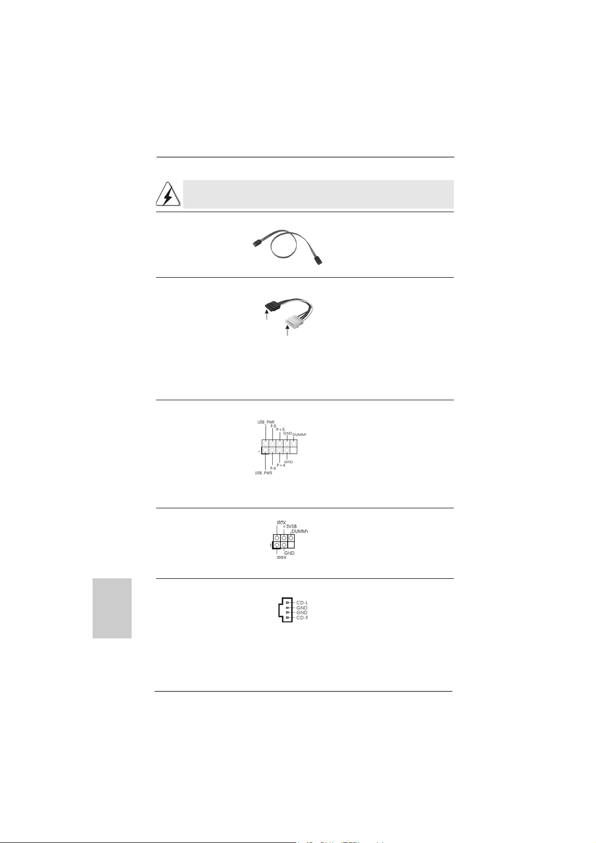
Il est recommandé de connecter le disque dur SATAII (SATAII_1) sur le connecteur
SATAII et le disque dur SA TA sur le connecteur SATA (SATA1, SATA2).
Câble de données L’une des deux extrémités du
Série ATA (SATA) câble de données SATA peut
(en option) être connectée au disque dur
SATA / SATAII ou au connecteur
SATA / SATAII ur la carte mère.
Cordon d’alimentation Veuillez connecter l’extrémité
Série ATA (SA TA) noire du cordon d’alimentation
(en option) SATA sur le connecteur
connecter au connecteur
d’alimentation du disque
dur SAT A
connecter à l’unité
d’alimentation
électrique
d’alimentation de l’unité.
Connectez ensuite l’extrémité
blanche du cordon d’alimentation
SATA sur le connecteur
d’alimentation de l’unité
d’alimentation électrique.
En-tête USB 2.0 A côté des quatre ports USB
(USB45 br.9) 2.0 par défaut sur le panneau
(voir p.2 No. 21) E/S, il y a un embases USB
2.0 sur cette carte mère.
Chaque emba se USB 2.0 peut
prendre en charge 2 ports USB
2.0.
Français
FrançaisFrançais
FrançaisFrançais
7676
76
7676
En-tête module Ce en-tête gère un module en
infrarouge option d’émission/réception
(IR1 br. 5) sans fil infrarouge.
(voir p.2 fig. 24)
Connecteurs audio internes Ils vous permettent de gérer des
(CD1 br. 4) entrées audio à partir de sources
(CD1: voir p.2 fig. 35) stéréo comme un CD-ROM,
CD1
DVD-ROM, un tuner TV ou une
carte MPEG.
ASRock 939Dual-VSTA Motherboard
Page 77

Connecteur audio panneau C’est une interfa ce pour un câble
avant audio en façade qui permet le
(AUDIO1 br. 8) branchement et le contrôle
(voir p.2 fig. 26) commodes de périphériques
audio.
Connecteur pour panneau Ce connecteur offre plusieurs
(PANEL1 br . 9) fonctions système en façade.
(voir p.2 fig. 17)
Connecteur du haut-parleur Veuillez connecter le hautdu châssis parleur de châssis sur ce
(SPEAKER1 br. 4) connecteur.
(voir p.2 fig. 18)
Connecteur pour ventilateur Veuillez connecter le câble du
de châssis ventilateur du châssis sur ce
(CHA_FAN1 br. 3) connecteur en branchant le fil
(voir p.2 fig. 19) noir sur la broche de terre.
Connecteur pour ventilateur Veuillez connecter un câble de
CPU ventilateur d’UC sur ce
(CPU_FAN1 br. 4) connecteur et brancher le fil noir
(voir p.2 fig. 3) sur la broche de terre.
Connecteur d’alimentation ATX V euillez connecter une unité
(ATXPW R1 br . 20) d’alimentation ATX sur ce
(voir p.2 fig. 2) connecteur.
Connecteur d’alimentation Veuillez noter qu’il est nécessaire
12V ATX de connecter une unité
(ATX12V1 br . 4) d’alimentation électrique avec
(voir p.2 fig. 4) prise ATX 12V sur ce
connecteur afin d’avoir une
alimentation suffisante. Faute de
quoi, il ne sera pas possible de
mettre sous tension.
ASRock 939Dual-VSTA Motherboard
7777
77
7777
çaisçais
çaisçais
çais
FranFran
FranFran
Fran
Page 78

Connecteur jeux Connectez un câble jeux sur ce
(GAME1 br. 15) connecteur si le support pour
(voir p.2 fig. 25) port jeux est installée.
2.72.7
Guide d’installation du disque dur SAGuide d’installation du disque dur SA
2.7
Guide d’installation du disque dur SA
2.72.7
Guide d’installation du disque dur SAGuide d’installation du disque dur SA
Avant d’installer le disque dur SATAII sur votre ordinateur, veuillez lire
attentivement le présent guide d’installation du disque dur SATAII. Certain
paramétrage par défaut des disques durs SATAII ne sont peut-être pas en mode
SATAII pour permettre un fonctionnement avec de meilleures performances. Pour
activer la fonction SATAII, veuillez suivre les instructions ci-dessous avec les
différents vendeurs pour paramétrer correctement votre disque dur SATAII au
mode SATAII avancé sous peine de voir votre disque dur SATAII ne pas
fonctionner en mode SATAII.
Western Digital
Pour activer SATA 1.5 Go/s, raccourcir les broches 5 et 6.
D’autre part, si vous voulez activer SATAII 3.0 Go/s, enlever le cavalier entre la
broche 5 et la broche 6.
TT
AIIAII
T
AII
TT
AIIAII
Français
FrançaisFrançais
FrançaisFrançais
7878
78
7878
SAMSUNG
Pour activer SATA 1.5 Go/s, raccourcir les broches 3 et 4.
D’autre part, si vous voulez activer SATAII 3.0 Go/s, enlever le cavalier entre la
broche 3 et la broche 4.
HITACHI
Veuillez utiliser la fonction Outil, outil pouvant être initié sous DOS, pour modifier
les différentes fonctions ATA. Merci de visiter le site HITACHI pour plus de détails.
http://www.hitachigst.com/hdd/support/download.htm
Les exemples donnés précédemment ne vous sont présentés qu’à titre
informatif. Pour les différents produits disques durs SATAIII provenant de
différents vendeurs, les méthodes de mise en place de cavaliers ne sont pas
les mêmes. Veuillez visiter le site Internet des vendeurs pour les mises à
jours.
ASRock 939Dual-VSTA Motherboard
Page 79

2.82.8
Installation des Disques Durs Serial AInstallation des Disques Durs Serial A
2.8
Installation des Disques Durs Serial A
2.82.8
Installation des Disques Durs Serial AInstallation des Disques Durs Serial A
AA
TT
AII (SAAII (SA
A
T
AII (SA
AA
TT
AII (SAAII (SA
Cette carte mère adopte le chipset JMicron JMB360 qui prend en charge le disque
durs Serial ATAII (SATAII). Elle adopte aussi le chipset ULi® M1567 south bridge qui
prend en charge les disques durs Serial ATA (SATA) et les fonctions RAID. Vous
pouvez installer les disques durs SATA / SATAII sur cette carte mère pour des
appareils de stockage interne. Cette section vous guidera pour installer les
disques durs SATA / SATAII.
ETAPE 1 : Installez les disques durs SATA / SATAII dans les baies pour disques de
ETAPE 2 : Connectez le câble d’alimentation SATA au disque dur SATA / SATAII.
ETAPE 3 : Connectez l’une des extrémités du câble de données SATA sur le
ETAPE 4 : Connectez l’autre extrémité du câble de données SATA au disque dur
2.92.9
Fonction “Hot Plug” et “Hot Swap” pour les Disques Fonction “Hot Plug” et “Hot Swap” pour les Disques
2.9
Fonction “Hot Plug” et “Hot Swap” pour les Disques
2.92.9
Fonction “Hot Plug” et “Hot Swap” pour les Disques Fonction “Hot Plug” et “Hot Swap” pour les Disques
Durs SA Durs SA
Durs SA
Durs SA Durs SA
La Carte Mère 939Dual-VSTA supporte la fonction “Hot Plug” pour les périphériques
SATA / SATAII.
TT
AII)AII)
T
AII)
TT
AII)AII)
votre châssis.
connecteur SATAII de la carte mère.
SATA / SATAII.
1. Si vous planifiez d’utiliser RAID 0, RAID 1, ou les fonctions JBOD sur SATA,
les lecteurs de disques durs SATA doivent fonctionner en mode “RAID”.
2. les modes “RAID” et “non-RAID” sont des options sous le “Mode Opératoire
SATA” dans la configuration du BIOS. Veuillez vous référer à la page 35 pour
plus de détails. Ils ont besoin de pilotes différents durant l’opération
actuelle.
TT
A / SAA / SA
TT
T
A / SA
TT
A / SAA / SA
AIIAII
T
AII
TT
AIIAII
TT
A (SAA (SA
T
A (SA
TT
A (SAA (SA
TT
A) / SerialA) / Serial
T
A) / Serial
TT
A) / SerialA) / Serial
REMARQUE
Qu’est-ce que la fonction « Hot Plug »?
Si les disques durs SATA / SATAII ne sont pas en configuration RAID,
l’action d’insérer et de retirer des disques SATA / SATAII alors que le
système est sous tension et en fonctionnement s’appelle le “Hot Plug”.
Qu’est-ce que la fonction « Hot Swap » ?
Si les disques durs sont montés en configuration RAID1 l’action d’insérer
et de retirer des disques SATA / SATAII alors que le système est sous
tension et en fonctionnement s’appelle le “Hot Swap” .
ASRock 939Dual-VSTA Motherboard
7979
79
7979
çaisçais
çaisçais
çais
FranFran
FranFran
Fran
Page 80

Français
FrançaisFrançais
FrançaisFrançais
2.102.10
Guide d’installation des pilotesGuide d’installation des pilotes
2.10
Guide d’installation des pilotes
2.102.10
Guide d’installation des pilotesGuide d’installation des pilotes
Pour installer les pilotes sur votre système, veuillez d’abord insérer le CD dans
votre lecteur optique. Puis, les pilotes compatibles avec votre système peuvent
être détectés automatiquement et sont listés sur la page du pilote du CD. Veuillez
suivre l’ordre de haut en bas sur le côté pour installer les pilotes requis. En
conséquence, les pilotes que vous installez peuvent fonctionner correctement.
2.112.11
Utilisation des lecteurs de disque dur SA Utilisation des lecteurs de disque dur SA
2.11
Utilisation des lecteurs de disque dur SA
2.112.11
Utilisation des lecteurs de disque dur SA Utilisation des lecteurs de disque dur SA
fonctions RAID fonctions RAID
fonctions RAID
fonctions RAID fonctions RAID
Les procédures d’installation pour Windows® VistaTM sont sujettes à modification.
“RAID” Si vous voulez installer Windows® 2000, Windows® XP, Windows® XP 64bit SE sur vos lecteurs de disques durs SATA, vous aurez besoin de faire une
disquette du pilote SATA avant de démarrer l’installation du SE.
ETAPE 1 : Insérez le CD de soutien ASRock dans votre lecteur de disque
optique pour démarrer votre système. (N’insérez AUCUNE
disquette dans le lecteur de disquette pour l’instant !)
ETAPE 2 : Pendant le POST au début du démarrage du système, appuyez
sur la touche <F11>, et une fenêtre s’af fiche pour la sélection des
périphériques de démarrage. Veuillez sélectionner le CD-ROM
comme périphérique de démarrage.
ETAPE 3 : Lorsque vous voyez s’afficher sur l’écran le message ”Do you
want to generate Serial ATA driver diskette [Y/N]?” (Voulez-vous
générer une disquette de pilotage Série ATA [Y/N]?), a ppuyez sur
<Y>.
ETAPE 4 : Vous voyez alors s’afficher les messages
Please insert a diskette into the floppy drive.
WARNING! Formatting the floppy diskette will
lose ALL data in it!
Start to format and copy files [Y/N]?
(Insérez une disquette dans le lecteur de disquette.
ATTENTION ! Le formatage de la disquette provoquera
la perte de toutes les données qui s’y trouvent !
Commencer à formater et à copier les fichiers [Y/N].)
Veuillez insérez une disquette dans le lecteur de disquette, et
appuyer sur <Y>.
ETAPE 5: Le système commencera à formater la disquette et copiera les
données des disques durs SATA vers la disquette.
TT
A avec lesA avec les
T
A avec les
TT
A avec lesA avec les
8080
80
8080
ASRock 939Dual-VSTA Motherboard
Page 81

Une fois la disquette des pilotes SATA prête, vous pouvez débuter directement
l’installation de Windows® 2000, Windows® XP, Windows® XP 64-bit sur votre
système, sans paramétrer la configuration RAID sur votre ordinateur, ou vous
pouvez commencer à utiliser le programme “RAID Installation Guide” pour effectuer la
configuration RAID 0 / RAID 1 / JBOD avant d’installer le système d’exploitation.
Avant de commencer à configurer la fonction RAID, vous devez vérifier le guide
d’installation sur le CD de support pour une configuration adaptée. Veuillez consulter
le document, “Guide pour Installation des Disques Durs SATA et Configuration RAID”
à l’emplacement suivant sur le CD de support :
.. \ Information \ Manual \ RAID Installation Guide \ French.pdf
Vous pouvez installerWindows® 2000 / Windows® XP / Windows® XP 64-bit. Au
début de la configuration Windows®, appuyez sur F6 pour installer un lecteur SCSI
ou RAID tiers. Lorsque vous y êtes invité, insérez une disquette contenant le
lecteur ULi® RAID. Après lecture de la disquette, le lecteur est présenté.
Sélectionnez le lecteur à installer en fonction du mode choisi et au système
d’exploitation installé.
2.122.12
Utilisation des lecteurs de disque dur SA Utilisation des lecteurs de disque dur SA
2.12
Utilisation des lecteurs de disque dur SA
2.122.12
Utilisation des lecteurs de disque dur SA Utilisation des lecteurs de disque dur SA
fonctions RAID fonctions RAID
fonctions RAID
fonctions RAID fonctions RAID
Les procédures d’installation pour Windows® VistaTM sont sujettes à modification.
Si vous voulez installer Windows® 2000, Windows® XP, Windows® XP 64-bit SE
on vos lecteurs de disques durs SATA fonctionnant en mode non-RAID , vous
n’avez pas besoin de faire une disquette du pilote SATA avant l’installation
du SE.
TT
A sans lesA sans les
T
A sans les
TT
A sans lesA sans les
1. Entrer en «SATA Operation Mode» dans la configuration du BIOS pour régler
l’option de [RAID] à [non-RAID].
2. Démarrer l’installation du système d’exploitation Windows® 2000 / XP / XP 64-bit.
2.132.13
SA SA
TT
2.13
2.132.13
Si vous voulez installer les systèmes d’exploitation Windows® 2000, Windows
XP, Windows® XP 64-bit sur vos disques durs SATAII fonctionnant en mode IDE,
vous n’avez pas besoin de faire une disquette du pilote du disque dur SATAII
avant l’installation du système d’exploitation.
AII fonctionnant en mode “IDE”AII fonctionnant en mode “IDE”
SA
T
AII fonctionnant en mode “IDE”
SA SA
TT
AII fonctionnant en mode “IDE”AII fonctionnant en mode “IDE”
Les procédures d’installation pour Windows® VistaTM sont sujettes à modification.
ASRock 939Dual-VSTA Motherboard
®
8181
81
8181
çaisçais
çaisçais
çais
FranFran
FranFran
Fran
Page 82

2.142.14
SA SA
TT
2.14
2.142.14
Si vous voulez installer les systèmes d’exploitation Windows® 2000, Windows
XP, Windows® XP 64-bit sur vos disques durs SATAII fonctionnant en mode
SATA, vous avez besoin de faire une disquette du pilote SATAII avant l’installation
du système d’exploitation.
1. Veuillez vous reporter au “Readme.txt” dans le répertoire du pilote SATAII sur le
CD pour les fichiers qui ont besoin d’être copiés sur la disquette. Faites une
disquette de SATAII.
2. Entrer en «SATAII Operation Mode» dans la configuration du BIOS pour régler
l’option de [IDE] à [SATA].
3. Démarrer l’installation du système d’exploitation Windows® 2000 / XP / XP 64-bit.
Au début de la configuration Windows®, appuyez sur F6 pour installer un
lecteur SCSI ou RAID tiers. Lorsque vous y êtes invité, insérez une disquette
contenant le lecteur JMicron® RAID. Après lecture de la disquette, le lecteur est
présenté. Sélectionnez le lecteur à installer en fonction du mode choisi et au
système d’exploitation installé.
2.15 La technologie de surcadençage à la volée2.15 La technologie de surcadençage à la volée
2.15 La technologie de surcadençage à la volée
2.15 La technologie de surcadençage à la volée2.15 La technologie de surcadençage à la volée
Cette carte mère prend en charge la technologie de surcadençage à la volée,
durant le surcadençage, FSB jouit d’une marge meilleure résultant des bus AGP /
PCI / PCIE fixés. Avant d’activer la technologie de surcadençage à la volée,
veuillez entrer l’option “Mode de surcadençage” de la configuration du BIOS pour
établir la sélection de [Auto] à [CPU, PCIE, Async.]. Par conséquent, le CPU FSB
n’est pas lié durant le surcadençage, mais les bus AGP / PCI / PCIE sont en mode
fixé de sorte que FSB peut opérer sous un environnement de surcadençage plus
stable.
AII fonctionnant en mode “SAAII fonctionnant en mode “SA
SA
T
AII fonctionnant en mode “SA
SA SA
TT
AII fonctionnant en mode “SAAII fonctionnant en mode “SA
Les procédures d’installation pour Windows® VistaTM sont sujettes à modification.
TT
A”A”
T
A”
TT
A”A”
®
Français
FrançaisFrançais
FrançaisFrançais
8282
82
8282
ASRock 939Dual-VSTA Motherboard
Page 83

3. Informations sur le BIOS3. Informations sur le BIOS
3. Informations sur le BIOS
3. Informations sur le BIOS3. Informations sur le BIOS
La puce Flash Memory sur la carte mère stocke le Setup du BIOS. Lorsque vous
démarrez l’ordinateur, veuillez presser <F2> pendant le POST (Power-On-SelfTest) pour entrer dans le BIOS; sinon, le POST continue ses tests de routine. Si
vous désirez entrer dans le BIOS après le POST, veuillez redémarrer le système
en pressant <Ctl> + <Alt> + <Suppr>, ou en pressant le bouton de reset sur le
boîtier du système.
Vous pouvez également redémarrer en éteignant le système et en le rallumant.
L’utilitaire d’installation du BIOS est conçu pour être convivial. C’est un programme
piloté par menu, qui vous permet de faire défiler par ses divers sous-menus et de
choisir parmi les choix prédéterminés. Pour des informations détaillées sur le
BIOS, veuillez consulter le Guide de l’utilisateur (fichier PDF) dans le CD technique.
4. Informations sur le CD de suppor4. Informations sur le CD de suppor
4. Informations sur le CD de suppor
4. Informations sur le CD de suppor4. Informations sur le CD de suppor
Cette carte mère supporte divers systèmes d’exploitation Microsoft® Windows®:
2000 / XP / XP 64-bit / VistaTM. Le CD technique livré avec cette carte mère
contient les pilotes et les utilitaires nécessaires pour améliorer les fonctions de la
carte mère.
Pour utiliser le CD technique, insérez-le dans le lecteur de CD-ROM. Le Menu
principal s’affiche automatiquement si “AUTORUN” est activé dans votre
ordinateur. Si le Menu principal n’apparaît pas automatiquement, localisez dans le
CD technique le fichier “ASSETUP.EXE” dans le dossier BIN et double-cliquez
dessus pour afficher les menus.
tt
t
tt
çaisçais
çaisçais
çais
FranFran
FranFran
Fran
ASRock 939Dual-VSTA Motherboard
8383
83
8383
Page 84

1. Introduzione
Grazie per aver scelto una scheda madre ASRock 939Dual-VSTA, una scheda
madre affidabile prodotta secondo i severi criteri di qualità ASRock. Le prestazioni
eccellenti e il design robusto si conformano all’impegno di ASRock nella ricerca della
qualità e della resistenza. Questa Guida Ra pida all’Installazione contiene l’introduzione
alla motherboard e la guida passo-passo all’installazione. Informazioni più dettagliate
sulla motherboard si possono trovare nel manuale per l’utente presente nel CD di
supporto.
Le specifiche della scheda madre e il software del BIOS possono
essere aggiornati, pertanto il contenuto di questo manuale può subire
variazioni senza preavviso. Nel caso in cui questo manuale sia
modificato, la versione aggiornata sarà disponibile sul sito di ASRock
senza altro avviso. Sul sito ASRock si possono anche trovare le più
recenti schede VGA e gli elenchi di CPU supportate.
ASRock website http://www.asrock.com
1.11.1
Contenuto della confezioneContenuto della confezione
1.1
Contenuto della confezione
1.11.1
Contenuto della confezioneContenuto della confezione
Scheda madre ASRock 939Dual-VSTA
(ATX Form Factor: 12.0-in x 9.6-in, 30.5 cm x 24.4 cm)
Guida di installazione rapida ASRock 939Dual-VSTA
CD di supporto ASRock 939Dual-VSTA
Un cavo IDE 80-pin Ultra AT A 66/100/133
Un cavo per floppy drive a 1,44 Mb
Un cavo dati Serial ATA (SATA) (Opzionale)
Un cavo alimentatore HDD Serial ATA (SATA) (Opzionale)
Un ASRock 8CH I/O Shield
Italiano
ItalianoItaliano
ItalianoItaliano
8484
84
8484
ASRock 939Dual-VSTA Motherboard
Page 85

1.21.2
SpecificheSpecifiche
1.2
Specifiche
1.21.2
SpecificheSpecifiche
Piattaforma - ATX Form Factor: 12.0-in x 9.6-in, 30.5 cm x 24.4 cm
Processore - Presa 939 pin che supporta processore AMD Athlon™ 64FX /
64X2 / 64
- Supporto tecnologia AMD Cool ‘n’ Quiet™(vedi ATTENZIONE 1)
- FSB 1000 MHz (2.0 GT/s)
- Supporta la tecnologia overclocking “slegata”
(vedi ATTENZIONE 2)
- Supporta la tecnologia Hyper-Transport
Chipset - Northbridge: ULi® M1695
- Southbridge: ULi® M1567
Memoria - Supporto tecnologia Dual Channel DD R Memory
(vedi ATTENZIONE 3)
- 4 x slot DDR DIMM
- Supporta DDR400/333/266
- Max. 4GB
Booster ibrido - Stepless control per frequenza del processore
(vedi ATTENZIONE 4)
- ASRock U-COP (vedi ATTENZIONE 5)
- Boot Failure Guard (B.F.G.)
Slot di - 1 x Future CPU Port (supporta l’aggiornamento CPU da AMD K8
espansione socket 939 CPU ad AM2 socket 940 CPU tramite scheda
AM2CPU) (vedere pagina 92 per dettagli)
- 3 x slot PCI
- 1 x slot PCI Express x16 (vedi ATTENZIONE 6)
- 1 x slot PCI Express x1
- 1 x slot AGP 8X (vedi ATTENZIONE 7)
Audio - C-Media CM6501 compatibile 7,1 canali audio con architettura
UAA
LAN - Realtek PHY RTL8201CL
- Velocità: 10/100 Ethernet
- Supporta Wake-On-LAN
Pannello ASRock 8CH I/O
posteriore I/O - 1 x porta PS/2 per mouse
- 1 x porta PS/2 per tastiera
- 1 x porta seriale: COM 1
- 1 x porta parallela: supporto ECP/EPP
- 4 x porte USB 2.0 già integrate
- 1 x porta RJ-45
ItalianoItaliano
ItalianoItaliano
Italiano
ASRock 939Dual-VSTA Motherboard
8585
85
8585
Page 86

Italiano
ItalianoItaliano
ItalianoItaliano
- Connettore Audio: cassa laterale / cassa posteriore / cassa
centrale / bassi / ingresso linea / cassa frontale / microfono
(vedi ATTENZIONE 8)
Connettori - 2 x connettori Serial ATA 1.5Go/s, sopporta RAID (RAID 0, RAID 1,
JBOD) e “Collegamento a caldo”
- 1 x connettore SATAII 3,0Gb/s marca JMicron JMB 360 (PCIE x1
interface), con supporto delle funzioni NCQ, AHCI e “Hot Plug”
(vedi ATTENZIONE 9)
- 2 x connettori ATA133 IDE (supporta fino a 4 dispositivi IDE)
- 1 x porta Floppy
- 1 x connettore modulo infrarossi
- 1 x connettore porta giochi
- Connettore ventolina CPU/telaio
- 20-pin collettore alimentazione ATX
- 4-pin connettore ATX 12V
- Connettori audio interni
- Connettore audio sul pannello frontale
- 1 x Collettore USB 2.0 (supporta 2 porte USB 2.0)
(vedi ATTENZIONE 10)
BIOS - 4Mb AMI BIOS
- Suppor AMI legal BIOS
- Supporta “Plug and Play”
- Compatibile con ACPI 1.1 wake up events
- Supporta jumperfree
- Supporta SMBIOS 2.3.1
CD di - Driver, utilità, software antivirus (Versione dimostrativa)
supporto
Monitor- - Sensore per la temperatura del processore
aggio - Sensore temperatura scheda madre
Hardware - Indicatore di velocità per la ventola del processore
- Indicatore di velocità per la ventola di raffreddamento
- Ventola CPU silenziosa
- Voltaggio: +12V, +5V, +3.3V, Vcore
Compatibi- - Microsoft® Windows® 2000 / XP / XP 64 bit / Vista
lità SO (vedi ATTENZIONE 11)
Certificazioni- FCC, CE, WHQL
TM
8686
86
8686
ASRock 939Dual-VSTA Motherboard
Page 87

ATTENZIONE!
1. Per risparmiare energia si raccomanda vivamente di abilitare la tecnologia
AMD Cool ‘n’ Quiet™ con i sistemi Windows. Fare riferimento a pagina 45
dell’APPENDICE del “Manuale dell’utente”, che si trova nel CD di
supporto, per abilitare la tecnologia AMD Cool ‘n’ Quiet™. Poiché non
tutte le CPU K8 a 939 pin possono supportare la tecnologia AMD Cool ‘n’
Quiet, verificare sul sito web AMD per i dettagli.
2. Questa scheda madre supporta la tecnologia overclocking “slegata”.
Per i dettagli leggere “Tecnologia di Untied Overclocking” a pagina 103.
3. Questa scheda madre supporta la tecnologia Dual Channel Memory.
Prima di implementare la tecnologia Dual Channel Memory, assicurarsi di
leggere la guida all’installazione dei moduli di memoria, a pagina 90, per
seguire un’installazione appropri ata.
4. Anche se questa motherboard offre il controllo stepless, non si consiglia
di effettuare l’overclocking. L’uso di frequenze diverse da quelle
raccomandate per il bus CPU possono provocare l’instabilità del sistema
o danneggiare la CPU.
5. Se il processore si surriscalda, il sistema si chiude automaticamente.
Prima di riavviare il sistema, assicurarsi che la ventolina CPU della
scheda madre funzioni correttamente; scollegare e ricollegare il cavo
d’alimentazione. Per migliorare la dissipazione del calore, ricordare di
applicare l’apposita pasta siliconica tra il processore e il dissipatore quando
si installa il sistema.
6. Per ottenere informazioni relativamente alle schede VGA PCI Express
compatibili, fare riferimento alla “Lista delle schede VGA ATi X300 e
X300SE serie PCI Express supportate” di pagina 9 (Solamente in Inglese).
Fare riferimento a pagina 92 della Guida all’installazione per informazioni
sull’appropriata installazione della scheda VGA PCI Express.
7. NON usare schede AGP da 3,3 V nello slot AGP di questa motherboard!
Ciò potrebbe provocare danni permanenti!
8. Questa scheda madre supporta l’ingresso stereo e mono per il microfono.
Questa scheda madre supporta le modalità 2 canali, 4 canali, 6 canali e 8
canali per l’uscita audio. Controllare la tavola a pagina 3 per eseguire il
collegamento appropriato.
9. Prima di installare il disco rigido SATAII al connettore SATAII, leggere la
“Guida di installazione del disco rigido SA TAII” a pagina 99 per regolare
l’unità disco SATAII in modalità SATAII. Si può anche connettere il disco
rigido SATA al connettore SATAII direttamente.
10. La Gestione Risorse per USB 2.0 funziona perfettamente con Microsoft
Windows® VistaTM / XP 64 bit / XP SP1; SP2/2000 SP4.
11. Il driver Microsoft® Windows® VistaTM non è ancora pronto. Vi terremo
aggiornati in futuro sul nostro sito web. Si prega di visitare il nostro sito
web per il driver Microsoft® Windows® VistaTM ed informazioni relative. Sito
web ASRock: http://www.asrock.com
®
ItalianoItaliano
ItalianoItaliano
Italiano
ASRock 939Dual-VSTA Motherboard
8787
87
8787
Page 88

1.31.3
TT
1.3
1.31.3
abella requisiti hardware minimi per Wabella requisiti hardware minimi per W
T
abella requisiti hardware minimi per W
TT
abella requisiti hardware minimi per Wabella requisiti hardware minimi per W
TMTM
TM
Logo VistaLogo Vista
Logo Vista
Logo VistaLogo Vista
Gli integratori di sistema e gli utenti che acquistano la nostra scheda
madre e desiderano inviare il logo Windows® VistaTM Premium e Basic
devono osservare la tabella di seguito sui requisiti hardware minimi.
Utilizzare CPU, memoria e VGA raccomandati.
CPU Athlon 3000+
Memoria 512MB ad un canale
VGA DX9.0 con driver WDDM
TMTM
Premium e Basic Premium e Basic
Premium e Basic
Premium e Basic Premium e Basic
Con memoria VGA 128bit (Premium)
Con memoria VGA 64bit (Basic)
indowsindows
indows
indowsindows
®
Italiano
ItalianoItaliano
ItalianoItaliano
8888
88
8888
ASRock 939Dual-VSTA Motherboard
Page 89

2. Installazione
Precauzioni preinstallazionePrecauzioni preinstallazione
Precauzioni preinstallazione
Precauzioni preinstallazionePrecauzioni preinstallazione
Leggere le seguenti precauzioni prima di installare componenti delle
schede madri o di cambiare le impostazioni delle schede madri.
1. Togliere il cavo dalla presa elettrica prima di toccare le componenti. In
caso contrario la schedamadre, le periferiche, e/o i componenti
possono subire gravi danni.
2. Per evitare che l’elettricità statica danneggi la scheda madre, NON
appoggiare la scheda madre su moquette, tappeti o tessuti simili.
Ricordarsi di indossare un braccialetto antistatico collegato a terra o di
toccare un oggetto posizionato a terra prima di maneggiare le
componenti.
3. Tenere i componenti per i bordi e non toccare i ICs.
4. Ogni volta che si disinstalla un componente, appoggiarlo su un
tappetino antistatico messo a terra o depositarlo nella borsa data in
dotazione con il componente.
5. Nell’usare i giraviti per fissare la scheda madre al telaio non serrare
eccessivamente le viti! Altrimenti si rischia di danneggiare la scheda
madre.
2.1 Installazione del processore2.1 Installazione del processore
2.1 Installazione del processore
2.1 Installazione del processore2.1 Installazione del processore
Step 1. Aprire lo zoccolo sollevando la leva da un angolo di 90°.
Step 2. Posizionare la CPU direttamente sopra la presa in modo tale che l’angolo
della CPU con il triangolo dorato corrisponda all’angolo della presa con il
triangolino.
Step 3. Inserire con cautela il processore nello zoccolo finché si adatta
perfettamente.
Il processore ha un solo corretto orientamento. NON forzare il
processore nello zoccolo: i pin potrebbero stortarsi.
Step 4. Quando il processore è posizionato, premere con decisione sullo zoccolo
mentre si abbassa la leva dello zonnettore per fissare il processore.
Quando la leva fa clic sulla linguetta laterale significa che è bloccata.
Step 5. Installare la ventola del processore e l’heatsink. Per una corretta
installazione, per favore fare riferimento ai manuali di istruzione dei
produttori della ventola e dell’heatsink del processore.
ASRock 939Dual-VSTA Motherboard
8989
89
8989
ItalianoItaliano
ItalianoItaliano
Italiano
Page 90
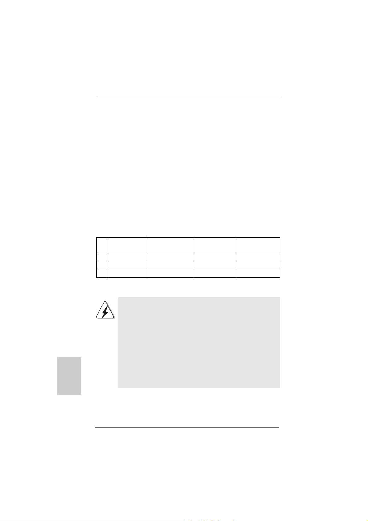
2.2 Installazione dei moduli di memoria (DIMM)2.2 Installazione dei moduli di memoria (DIMM)
2.2 Installazione dei moduli di memoria (DIMM)
2.2 Installazione dei moduli di memoria (DIMM)2.2 Installazione dei moduli di memoria (DIMM)
La scheda madre 939Dual-VSTA fornisce quattro alloggiamenti DIMM DDR (Double
Data Rate) a 184 pin, e supporta la tecnologia Dual Channel Memory. Per la
configurazione a due canali, è necessario installare sempre coppie identiche
(stessa marca, velocità, dimensioni e tipo di chi p) di DIMM DDR negli alloggiamenti
dello stesso colore. In altre parole, è necessario installare coppie identiche di DIMM
DDR nel canale doppio A (DD R1 e DDR2; alloggiamenti blu; vedere pag. 2 Nr . 7)
oppure coppie identiche di DIMM DDR nel canale doppio B (DDR3 e DDR4;
alloggiamenti neri; vedere pag. 2 Nr. 8), per fare sì che la tecnologia Dual Channel
Memory possa essere attivata. Questa scheda madre consente anche di
installare quattro DIMM DDR per la configurazione a canale doppio.Questa scheda
madre consente anche di installare quattro DIMM DDR per configurazione a canale
duale, si raccoma nda di in stallare DIMM DDR identiche ne i quattro alloggi amenti.
Consultare la Tabella configurazione Memoria Canale Duale di seguito.
Configurazioni Dual Channel Memory
DDR1 DDR2 DDR3 DDR4
(alloggia mento blu) (alloggi a mento blu) (alloggiamento nero) (alloggia mento nero)
(1) Popolato Popolato - (2) - - Popolato Popolato
(3) Popolato Popolato Popolato Popolato
* Per la configurazione (3), installare DDR DIMM identici nei quattro slot.
Italiano
ItalianoItaliano
ItalianoItaliano
9090
90
9090
1. Se si vogliono installare due moduli di memoria, per ottenere
compatibilità ed affidabilità ottimali, si raccomanda di installarli negli
alloggia menti dello stesso colore. In altre parole: in stallare i moduli di
memoria o nella serie di alloggiamenti blu (DDR1 e DDR2) oppure
nella serie di alloggiamenti nera (DDR3 e DDR4).
2. Se negli alloggiamenti DIMM di questa scheda madre è installato un
solo modulo di memoria, oppure sono installati tre moduli di memoria,
è impossibile attivare la tecnologia Dual Channel Memory.
3. Se una coppia di moduli di memoria NON è installata nello stesso
“canale doppio”, ad esempio se si installa una coppia di moduli di
memoria su DDR1 e DD3, è impossibile attivare la tecnologia
Dual Channel Memory.
ASRock 939Dual-VSTA Motherboard
Page 91

Installare una DIMMInstallare una DIMM
Installare una DIMM
Installare una DIMMInstallare una DIMM
Scollegare l’alimentazione elettrica prima di aggiungere o rimuovere i
DIMM o altri componenti del sistema.
Step 1. Sbloccare lo slot DIMM premendo i fermi che lo trattengono verso
l’esterno.
Step 2. Allineare una DIMM sullo slot così che il pettine della DIMM combaci con
la sua sede sullo slot.
La DIMM può essere montata correttamente soltanto con un
orientamento. Se si dovesse installare a forza la DIMM nello slot con
un orientamento errato, si causerebbero danni permanenti alla scheda
madre e alla DIMM stessa.
Step 3. Inserire saldamente la DIMM nello slot fino a far scattare completamente
in posizione i fermagli di ritegno alle due estremità e fino ad installare
correttamente la DIMM nella sua sede.
ASRock 939Dual-VSTA Motherboard
9191
91
9191
ItalianoItaliano
ItalianoItaliano
Italiano
Page 92
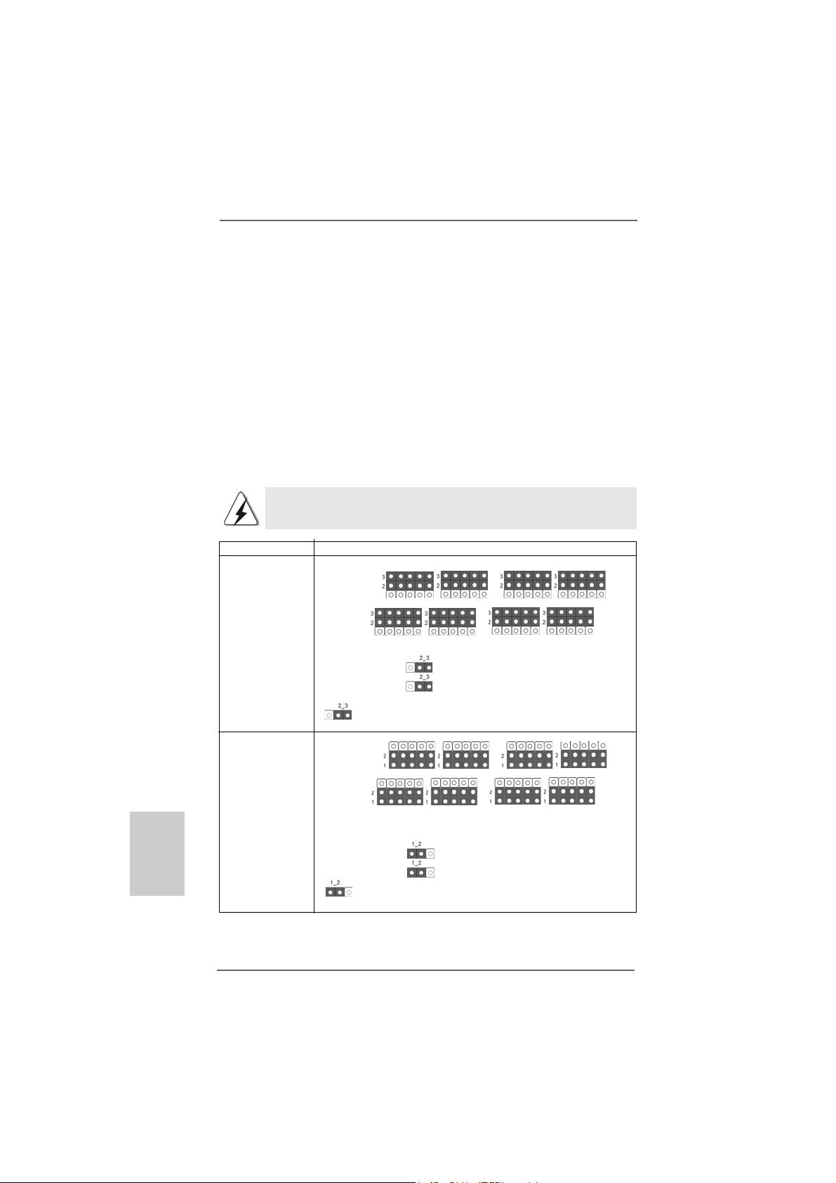
2.32.3
Slot di espansioneSlot di espansione
2.3
Slot di espansione
2.32.3
Slot di espansioneSlot di espansione
(Porta CPU Future, Slot PCI, Slot PCIE ed Slot AGP)(Porta CPU Future, Slot PCI, Slot PCIE ed Slot AGP)
(Porta CPU Future, Slot PCI, Slot PCIE ed Slot AGP)
(Porta CPU Future, Slot PCI, Slot PCIE ed Slot AGP)(Porta CPU Future, Slot PCI, Slot PCIE ed Slot AGP)
Sulla scheda madre 939Dual-VSTA c’è 1 porta CPU Future, 3 slot PCI, 2 slot PCIE
ed 1 slot AGP.
Porta CPU futura (Porta di colore giallo):
La porta CPU futura consente di effettuare l’aggiornamento da AMD K8 939-Pin
CPU a AMD AM2 940-Pin CPU installa ndo un a dd-on ASRock AM2CPU Board nella
porta CPU futura su scheda madre 939Dual-VSTA. Prima di eseguire
l’aggiorna mento della K8 939-Pin CPU in AM2 940-Pin CPU, è necessario sistemare
le impostazioni dei jumper per la disposizione richiesta per la scheda madre
939Dual-VSTA. Per le impostazioni corrette dei jumper consultare la tabella
riportata di seguito.
Questa porta CPU Future di colore giallo non è un alloggiamento
AGP! NON inserirvi alcuna scheda AGP!
Italiano
ItalianoItaliano
ItalianoItaliano
Tipo di CPU
CPU 939 pin
(Impostazione
predefinita)
CPU AM2 940 pin
(Utilizzando
la scheda aggiuntiva
ASRock AM2CPU)
Impostazioni dei jumper
J3 J4 J7 J8
J1 J2
J10
J9
J11
J3 J4 J7 J8
J1 J2
J10
J9
J11
J5 J6
J5 J6
9292
92
9292
ASRock 939Dual-VSTA Motherboard
Page 93

NOTA
Quando si regolano le impostazioni dei jumper, si può utilizzare l’apposito attrezzo per
facilitare la rimozione dei cappucci dei jumper. Questo attrezzo è allegato alla confezione
della scheda madre; seguire le “Istruzioni per la rimozione dei cappucci jumper” per utilizzarlo
in modo appropriato.
Slot PCI: Sono utilizzati per installare schede di espansione con Interfaccia PCI
a 32-bit.
Slot PCI Express:
PCIE1 (slot PCIE x16) usato per schede PCI Express con schede
grafiche di larghezza x16. Per le informazioni sulle schede VGA PCI
Express compatibili, fare riferimento a ”Elenco schede VGA ATi X300 e
X300SE serie PCI Express per slot PCI Express (PCI Express x16)” a
pagina 9. PCIE2 (slot PCIE x1) usato per schede PCI Express con
schede grafiche di larghezza x1, quali scheda Gigabit LAN, SATA 2,
ecc.
Slot AGP: Lo slot AGP serve all’installazione di schede grafiche. Lo slot AGP
ASRock usa uno speciale gancio che permette di fissare in sede in
modo sicuro la scheda grafica.
NON usare schede AGP da 3,3 V nello slot AGP di questa
motherboard! Ciò potrebbe provocare danni permanenti! Per le
informazioni relative alla tensione della scheda AGP, si prega di
contattare il fornitore della scheda AGP.
Installare una scheda di espansioneInstallare una scheda di espansione
Installare una scheda di espansione
Installare una scheda di espansioneInstallare una scheda di espansione
Step 1. Prima d’installare la scheda di espansione, assicurarsi che l’alimentazione
sia stata esclusa oppure che il cavo di alimentazione sia scollegato. Prima
di iniziare l’installazione, si prega di leggere la documentazione della scheda
di espansione e di effettuare le necessarie impostazioni del hardware.
Step 2. Rimuovere i ganci sullo slot che si intende utilizzare. Tenere a portata di ma no
le viti.
Step 3. Allineare il connettore della scheda con lo slot e premere con decisione
finché la scheda è completamente inserita nello slot.
Step 4. Agganciare la scheda allo chassis con le viti.
2.4 “Surround Display”2.4 “Surround Display”
2.4 “Surround Display”
2.4 “Surround Display”2.4 “Surround Display”
Questa scheda madre supporta l’aggiornamento Surround Display. Con la scheda
integrativa AGP VGA e la scheda PCI Express VGA, si possono sfruttare con
facilità i benefici della funzione Surround Display. Per le istruzioni dettagliate, fare
riferimento al documento nel seguente percorso sul CD di supporto:
..\ Surround Display Information
ASRock 939Dual-VSTA Motherboard
9393
93
9393
ItalianoItaliano
ItalianoItaliano
Italiano
Page 94
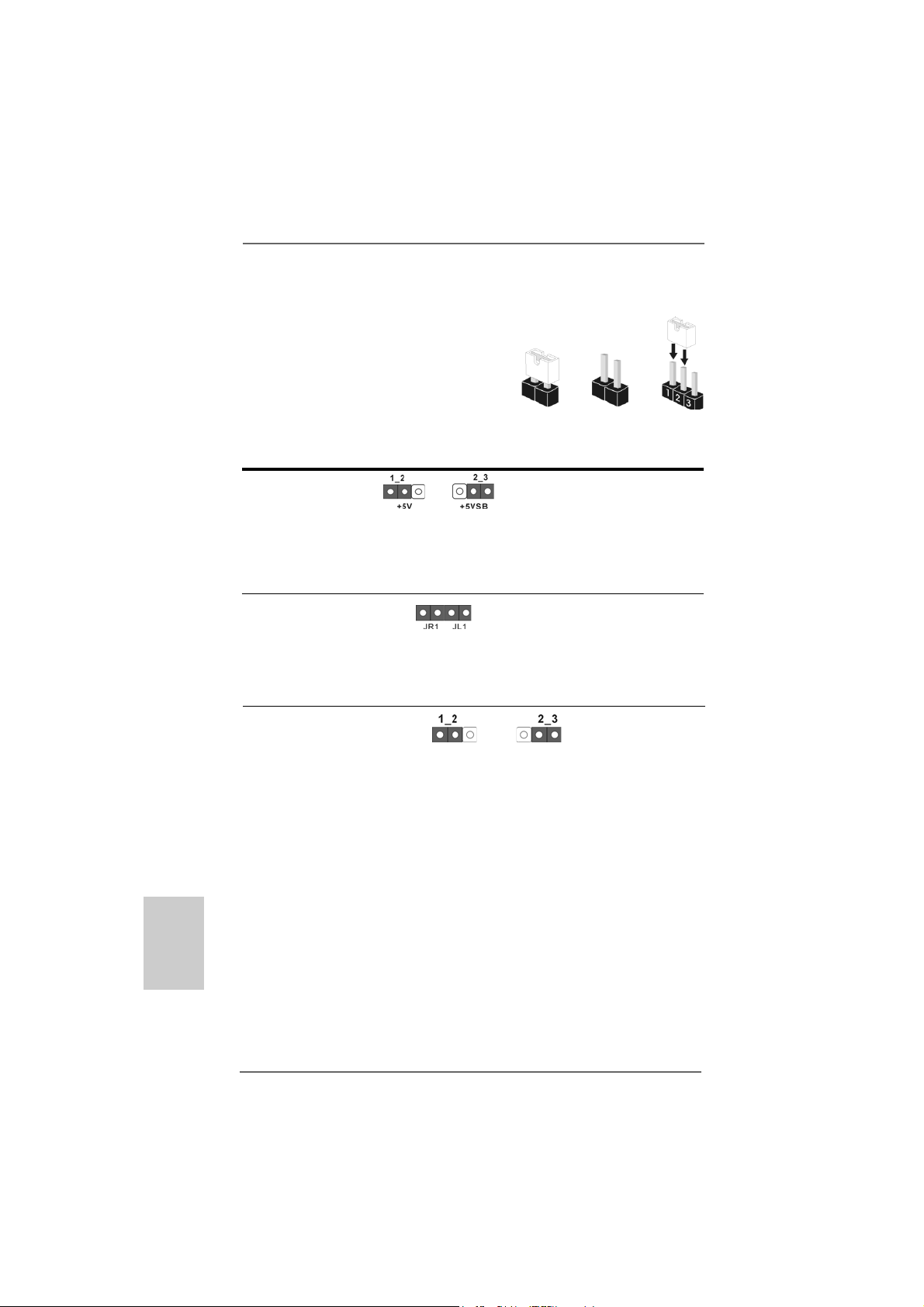
Italiano
ItalianoItaliano
ItalianoItaliano
2.5 Setup dei Jumpers2.5 Setup dei Jumpers
2.5 Setup dei Jumpers
2.5 Setup dei Jumpers2.5 Setup dei Jumpers
L’illustrazione mostra come sono settati i jumper.
Quando il ponticello è posizionato sui pin, il jumper
è “CORTOCIRCUITATO”. Se sui pin non ci sono
ponticelli, il jumper è “APERTO”. L’illustrazione
mostra un jumper a 3 pin in cui il pin1 e il pin2 sono
“CORTOCIRCUITATI” quando il ponticello è
posizionato su questi pin.
Jumper Settaggio del Jumper
PS2_USB_PWR1 Cortocircuitare pin2, pin3 per
(vedi p.2 item 1) settare a +5VSB (standby) e
Nota: Per selezionare +5VSB, si richiedono almeno 2 Ampere e il consumo di
corrente in standby sarà maggiore.
Jumper JR1 JL1
(vedi p.2 item 27)
Nota: S e i jumper JR1 e JL1 sono in corto, possono funzionare i connettori audio
del pannello frontale e del pannello posteriore.
Resettare la CMOS Jumper
(CLRTC1)
(vedi p.2 No. 20)
Nota: CLRTC1 permette di cancellare i dati presenti nel CMOS. I dati del CMOS
comprendono le informazioni di configurazione quali la password di sistema,
data, ora, e i parametri di configurazione del sistema. Per cancellare e
ripristinare i parametri del sistema, spegnere il computer e togliere il cavo di
alimentazione dalla presa di corrente. Dopo aver lasciato trascorrere 15
secondi, utilizzare un cappuccio jumper per cortocircuitare i pin 2 e 3 su
CLRTC1 per 5 secondi. Dopo aver cortocircuitato il jumper Clear CMOS
jumper, togliere il terminatore jumper. Non cancellare la CMOS subito dopo
aver aggiornato il BIOS. Se è necessario cancellare la CMOS una volta
completato l’aggiornamento del BIOS, è necessario riavviare prima il sistema,
e poi spegnerlo prima di procedere alla cancellazione della CMOS.
Impostazione
predefinita
CORTOCIRCUIT ATO APERT O
abilitare PS/2 o USB wake up
events.
Azzeramento
CMOS
9494
94
9494
ASRock 939Dual-VSTA Motherboard
Page 95

2.6 Connettori2.6 Connettori
2.6 Connettori
2.6 Connettori2.6 Connettori
I connettori NON sono jumpers. NON COLLOCARE i ponticelli sui
connettori. Installando dei cappucci a ponticello sui connettori si
causeranno danni permanenti alla scheda madre!
Connettori Descrizione dei connettori
Connettore del
Floppy disk
(33-pin FLOPPY1)
(vedi p.2 item 23)
Lato del Pin1 con la striscia rossa
Nota: Assicurarsi che il lato del cavo con la striscia rossa sia inserito nel lato Pin1
del connettore.
Connettore IDE primario (blu) Connettore IDE secondario (nero)
(39-pin IDE1, vedi p.2 item 15) (39-pin IDE2, vedi p.2 item 16)
Connettore blu Connettore nero
alla scheda madre all’hard disk drive
Cavo ATA 66/100/133 a 80 pin
Nota: Se utilizzate un solo dispositivo IDE su questa scheda madre, imposta tale
dispositivo come “Master”. Fate riferimento alle istruzioni del produttore del
dispositivo IDE per maggiori dettagli. Inoltre, per ottimizzare compatibilità e
prestazioni, connettete l’hard disk al connettore primario IDE (IDE1, blu) e il
CD-ROM al connettore IDE secondario (IDE2, nero).
Connettori Serial ATA (Nero) Questi due connettori Serial
(SAT A1: vedi p.2 No. 14) ATA (SATA) supportano cavi
(SAT A2: vedi p.2 No. 13) dati SATA per dispositivi di
SAT A2
immagazzina mento interni.
SAT A1
ATA (SATA) supportano cavi
SATA per dispositivi di memoria
interni. L’interfaccia SATA
attuale permette velocità di
trasferimento dati fino a 1.5 Gb/s.
Connettori Serial ATAII (Rosso) Questi due connettori Serial
(SAT AII_1: vedi p.2 Nr. 10) ATAII (SATAII) supportano cavi
SATA II_1
dati SATAII per dispositivi di
immagazzina mento interni.
ASRock 939Dual-VSTA Motherboard
9595
95
9595
ItalianoItaliano
ItalianoItaliano
Italiano
Page 96

ATAII (SATAII) supportano cavi
SATA per dispositivi di memoria
interni. L’interfaccia SATAII
attuale permette velocità di
trasferimento dati fino a 3.0
Gb/s.
Si raccomanda di collegare il disco rigido SATAII al connettore SATAII (SATAII_1)
e di collegare il disco rigido SATA al connettore SATA (SATA1, SATA2).
Cavi dati Serial ATA (SATA) Entrambe le estremità del cavo
(Opzionale) dati SATA possono collegarsi
all’hard disk SATA / SATAII o al
connettore SATA / SATAII sulla
scheda madre.
Cavo d’alimentazione Collegare l’estremità nera de
Serial A TA (SATA) cavo di alimentazione SATA al
(Opzionale) connettore di alimentazione del
Connettere all’ailmentazione
dei dischi SAT A
Connettere al gruppo
di alimentazione
drive. Poi connettete l’estremità
bianca del cavo di
alimentazione SATA al
connettore power
dell’alimentatore.
Collettore USB 2.0 Oltre alle quattro porte USB 2.0
(9-pin USB45) predefinite nel pannello I/O, la
(vedi p.2 No. 21) scheda madre dispone di uno
intestazioni USB 2.0. Ciascuna
intestazione USB 2.0 supporta
due porte USB 2.0.
Italiano
ItalianoItaliano
ItalianoItaliano
9696
96
9696
Collettore modulo Questo collettore supporta
infrarossi una wireless opzionale che
(5-pin IR1) trasmette e riceve moduli
(vedi p.2 item 24) infrarossi.
ASRock 939Dual-VSTA Motherboard
Page 97

Connettori audio interni Permettono di ricevere input
(4-pin CD1) stereo audio da fonti di
(CD1: vedi p.2 item 35) suono come CD-ROM, DVD -
CD1
ROM,TV tuner, o schede
MPEG.
Connettore audio sul È un’interfaccia per il cavo del
pannello frontale pannello audio. Che consente
(8-pin AUDIO1) connessione facile e controllo
(vedi p.2 item 26) dei dispositivi audio.
Connettore del panello Questo connettore accoglie
frontale diverse funzioni del pannello
(9-pin PANEL1) frontale.
(vedi p.2 item 17)
Collettore casse telaio Collegare le casse del telaio a
(4-pin SPEAKER1) questo collettore.
(vedi p.2 item 18)
Connettore ventolina telaio Collegare il cavo della ventolina
(3-pin CHA_FAN1) telaio a questo connettore e far
(vedi p.2 item 19) combaciare il filo nero al pin
terra.
Connettore ventolina CPU Collegare il cavo della ventolina
(4-pin CPU_FAN1) CPU a questo connettore e far
(vedi p.2 item 3) combaciare il filo nero al pin
terra.
Collettore alimentazione ATX Collegare la sorgente
(20-pin ATXPW R1) d’alimentazione ATX a questo
(vedi p.2 item 2) collettore.
ASRock 939Dual-VSTA Motherboard
9797
97
9797
ItalianoItaliano
ItalianoItaliano
Italiano
Page 98

Connettore ATX 12V È necessario collegare una
(4-pin ATX12V1) alimentazione con spinotto da
(vedi p.2 item 4) 12V ATX a questo connettore
in modo che possa fornire
energia sufficiente. In caso
contrario l’unità non si avvia.
Connettore porta giochi Connettere un cavo Game a
(15-pin GAME1) questo connettore solo se la
(vedi p.2 item 25) porta giochi è installata.
Italiano
ItalianoItaliano
ItalianoItaliano
9898
98
9898
ASRock 939Dual-VSTA Motherboard
Page 99

2.72.7
Giuda all’installazione del disco rigido SAGiuda all’installazione del disco rigido SA
2.7
Giuda all’installazione del disco rigido SA
2.72.7
Giuda all’installazione del disco rigido SAGiuda all’installazione del disco rigido SA
Prima di installare il disco rigido SATAII nel computer, leggere attentamente la guida
del disco rigido SATAII in basso. Alcune impostazioni predefinite dei dischi rigidi
SATAII possono non essere in modalità SATAII, che opera con la migliore
prestazione. Per abilitare la funzione SATAII, seguire le istruzioni in basso in base
ai differenti produttori per regolare correttamente e anticipatamente, il disco rigido
SATAII in modalità SATAII; in caso contrario, il disco rigido SATAII potrebbe non
girare in modalità SATAII.
Western Digital
Se i pin 5 e 6 vengono cortocircuitati, verrà abilitato il SATA 1.5Gb/s.
Diversamente, se si desidera abilitare il SATAII 3.0Gb/s, rimuovere i jumper dal pin
5 e dal pin 6.
SAMSUNG
Se i pin 3 e 4 vengono cortocircuitati, verrà abilitato il SATA 1.5Gb/s.
Diversamente, se si desidera abilitare il SATAII 3.0Gb/s, rimuovere i jumper dal pin
3 e dal pin 4.
TT
T
TT
AIIAII
AII
AIIAII
HITACHI
Usare lo strumento di funzione, uno strumento avviabile da DOS per passare da
una funzione ATA all’altra. Visitare il sito web HITACHI per i dettagli:
http://www.hitachigst.com/hdd/support/download.htm
Gli esempi di cui sopra sono solo per riferimento. Per dischi rigidi SATAII di
diversi produttori, i metodi di impostazione dei pin del jumper possono non
essere gli stessi. Visitare i siti web dei produttori per gli aggiornamenti.
ASRock 939Dual-VSTA Motherboard
9999
99
9999
ItalianoItaliano
ItalianoItaliano
Italiano
Page 100

2.82.8
Installazione di Hard Disk AInstallazione di Hard Disk A
2.8
Installazione di Hard Disk A
2.82.8
Installazione di Hard Disk AInstallazione di Hard Disk A
(SA(SA
TT
AII)AII)
(SA
T
AII)
(SA(SA
TT
AII)AII)
Questa scheda madre adotta il chipset JMicron JMB360 che supporta il disco
rigido seriale ATAII (SATAII). Adotta anche il chipset south bridge ULi® M1567 che
supporta i dischi rigidi seriali Serial ATA (SATA) e le funzioni RAID. E possibile
installare su questa scheda madre i dischi rigidi SATA / SATAII come periferiche
interne di archiviazione. Questa sezione vi guiderà nell’installazione dei dischi rigidi
SATA / SATAII.
1° PASSO: Installare gli Hard Disk SATA / SATAII negli spazi per le unità disco del
telaio.
2° PASSO: Collegare il cavo d’alimentazione SATA al disco rigido SATA / SATAII.
3° PASSO: Collegare un’estremità del cavo dati SATA al connettore SATAII della
motherboard.
4° PASSO: Collegare l’altra estremità del cavo dati SATA all’hard disk SATA /
SATAII.
1. Per utilizzare le funzioni RAID 0, RAID 1 o JBOD su SATA, gli hard disk SATA
devono operare in modalità “RAID”.
2. Le modalità “RAID” e “non RAID” possono essere selezionate nella
configurazione del BIOS sotto “SATA Operation Mode” (Modalità operativa
SATA). Per ulteriori particolari vedi pag. 35 Le due modalità richiedono driver
diversi in fase d’uso effettivo.
2.92.9
Funzione di collegamento e scambio a caldo per iFunzione di collegamento e scambio a caldo per i
2.9
Funzione di collegamento e scambio a caldo per i
2.92.9
Funzione di collegamento e scambio a caldo per iFunzione di collegamento e scambio a caldo per i
dischi rigidi SAdischi rigidi SA
dischi rigidi SA
dischi rigidi SAdischi rigidi SA
La scheda madre 939Dual-VSTA supporta la funzione di collegamento e scambio
a per i dispositivi SATA / SATAII.
TT
A / SAA / SA
T
A / SA
TT
A / SAA / SA
TT
A Seriali (SAA Seriali (SA
T
A Seriali (SA
TT
A Seriali (SAA Seriali (SA
TT
AIIAII
T
AII
TT
AIIAII
TT
A) / AA) / A
T
A) / A
TT
A) / AA) / A
TT
AII SerialiAII Seriali
T
AII Seriali
TT
AII SerialiAII Seriali
Italiano
ItalianoItaliano
ItalianoItaliano
100100
100
100100
NOTA
Che cosa è la funzione di collegamento a caldo?
Se i dischi rigidi SATA / SATAII NON sono impostati per una
configurazione RAID, è detta “collegamento a caldo” l’azione
d’inserimento e rimozione dei dischi rigidi SATA / SATAII mentre il
sistema è ancora acceso ed in condizione di funzionamento.
Che cosa è la funzione di scambio a caldo?
Se i dischi rigidi SATA / SATAII sono impostati in una configurazione
RAID1 allora è detta “scambio a caldo” l’azione d’inserimento e
rimozione dei dischi rigidi SATA / SATAII mentre il sistema è ancora
acceso ed in condizione di funzionamento.
ASRock 939Dual-VSTA Motherboard
 Loading...