

Page 1
Copyright Notice:Copyright Notice:
Copyright Notice:
Copyright Notice:Copyright Notice:
No part of this installation guide may be reproduced, transcribed, transmitted, or translated in any language, in any form or by any means, except duplication of documentation by the purchaser for backup purpose, without written consent of ASRock Inc.
Products and corporate names appearing in this guide may or may not be registered
trademarks or copyrights of their respective companies, and are used only for identification or explanation and to the owners’ benefit, without intent to infringe.
Disclaimer:Disclaimer:
Disclaimer:
Disclaimer:Disclaimer:
Specifications and information contained in this guide are furnished for informational
use only and subject to change without notice, and should not be constructed as a
commitment by ASRock. ASRock assumes no responsibility for any errors or omissions
that may appear in this guide.
With respect to the contents of this guide, ASRock does not provide warranty of any kind,
either expressed or implied, including but not limited to the implied warranties or
conditions of merchantability or fitness for a particular purpose. In no event shall
ASRock, its directors, officers, employees, or agents be liable for any indirect, special,
incidental, or consequential damages (including damages for loss of profits, loss of
business, loss of data, interruption of business and the like), even if ASRock has been
advised of the possibility of such damages arising from any defect or error in the guide
or product.
This device complies with Part 15 of the FCC Rules. Operation is subject to the
following two conditions:
(1) this device may not cause harmful interference, and
(2) this device must accept any interference received, including interference that
may cause undesired operation.
CALIFORNIA, USA ONLY
The Lithium battery adopted on this motherboard contains Perchlorate, a toxic
substance controlled in Perchlorate Best Management Practices (BMP) regulations
passed by the California Legislature. When you discard the Lithium battery in
California, USA, please follow the related regulations in advance.
“Perchlorate Material-special handling may apply, see
www.dtsc.ca.gov/hazardouswaste/perchlorate”
ASRock Website: http://www.asrock.com
Published January 2011
Copyright©2011 ASRock INC. All rights reserved.
ASRock 880G Pro3 Motherboard
EnglishEnglish
EnglishEnglish
English
11
1
11
Page 2
English
EnglishEnglish
EnglishEnglish
Motherboard LayoutMotherboard Layout
Motherboard Layout
Motherboard LayoutMotherboard Layout
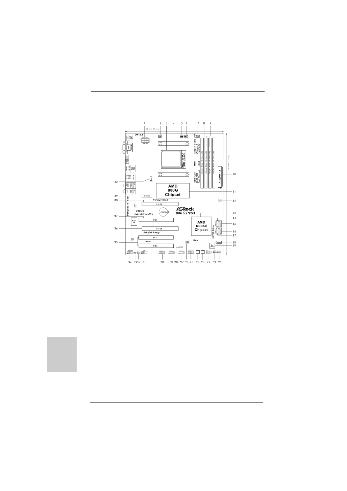
1 A TX 12V Power Connector (A TX12V1) 22 System Panel Hea der (PANEL1, White)
2 Power Fan Connector (PWR_FAN1) 23 Reset Switch (RSTBTN)
3 AM3+ CPU Socket 24 Power Switch (PWRBT N)
4 CPU Heatsink Retention Module 25 Front Panel IEEE 1394 Header
5 CPU Fan Connector (CPU_FAN2) (FRONT_1394, White)
6 CPU Fan Connector (CPU_FAN1) 26 SPI Flash Memory (32Mb)
7 Chassis Fan Connector (CHA_FAN2) 27 USB 2.0 Header (USB10_11, Blue)
8 2 x 240-pin DDR3 DIMM Slots 28 Clear CMOS Jumper (CLRCMOS1)
(Dual Channel A: DDR3_A1, DDR3_B1; Blue) 29 SB 2.0 Header (USB8_9, Blue)
9 2 x 240-pin DDR3 DIMM Slots 30 SB 2.0 Header (USB6_7, Blue)
(Dual Channel B: DDR3_A2, DDR3_B2; White) 31 Serial Port Connector (COM1)
10 ATX Power Connector (ATXPWR1) 32 Infrared Module Header (IR1)
11 Northbridge Controller 33 HDMI_SPDIF Header
12 Chassis Fan Connector (CHA_FAN3) (HDMI_SPDIF1, White)
13 Southbridge Controller 34 Front Panel Audio Header
14 SA T A3 Connector (SA TAIII_3, White) (HD_AUDIO1, White)
15 SA T A3 Connector (SA TAIII_4, White) 35 PCI Slots (PCI2-3)
16 SA T A3 Connector (SA TAIII_2, White) 36 PCI Express 2.0 x16 Slot (PCIE3; Blue)
17 SA T A3 Connector (SA TAIII_1, White) 37 PCI Slot (PCI1)
18 SA T A3 Conne ctor (SA TA3_5, White) 3 8 PCI Express 2.0 x16 Slot (PCIE2; Blue)
19 Dr. Debug (LED) 39 PCI Express 2.0 x1 Slot (PCIE1; White)
20 Chassis Speaker Header (SPEAKER 1, White) 40 Chassis Fan Connector (CHA_FAN1)
21 Power LED Header (PLED1)
22
2
22
ASRock 880G Pro3 Motherboard
Page 3
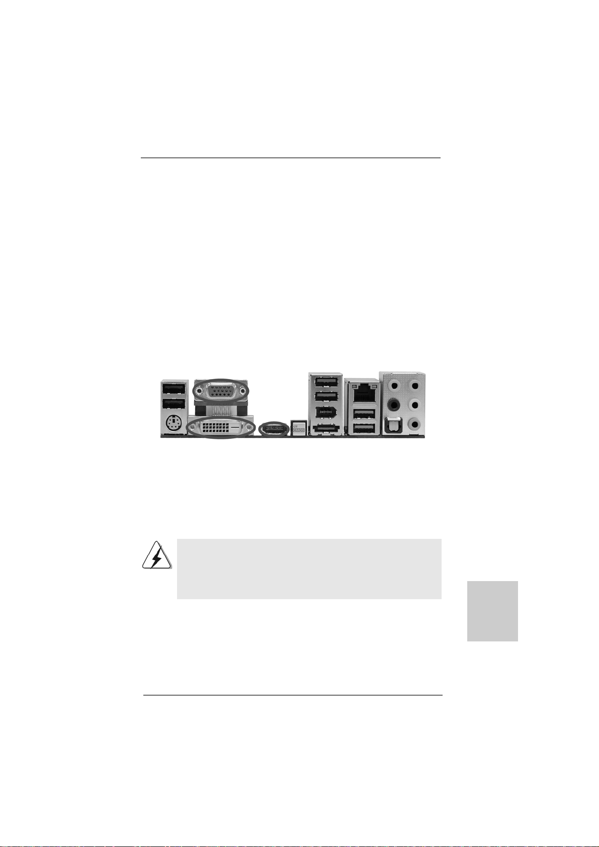
I/O PI/O P
I/O P
I/O PI/O P
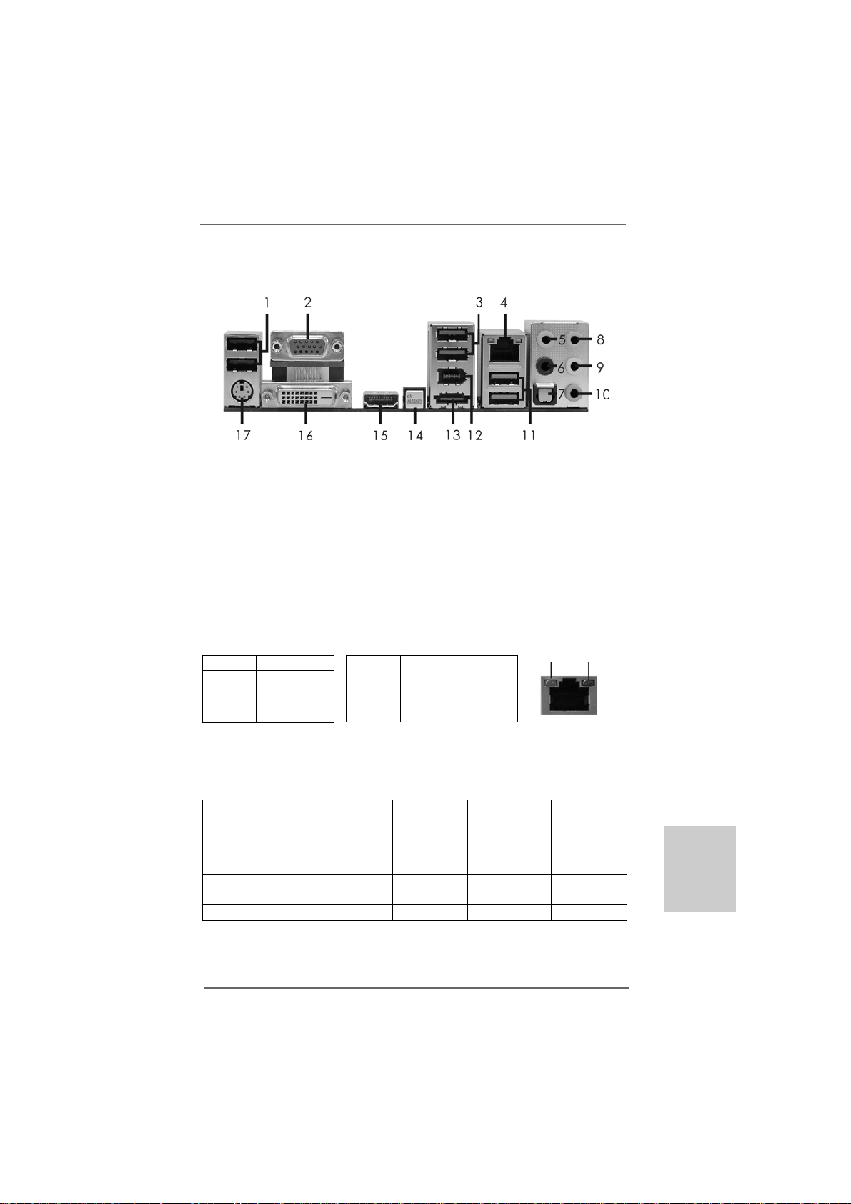
* 4 LAN RJ-45 Port *** 13 eSA TA3 Connector
** 9 Front Speaker (Lime)
* There are two LED next to the LAN port. Please refer to the table below for the LAN port LED
indications.
anelanel
anel
anelanel
1 USB 2.0 Ports (USB45) 10 Microphone (Pink)
2 VGA/D-Sub Port 11 USB 3.0 Port (USB01)
3 USB 2.0 Ports (USB23) 12 IEEE 1394 Port (IEEE 1394)
5 Central / Bass (Orange) 14 Clear CMOS Switch (CLRCBTN)
6 Rear Speaker (Black) 15 VGA/HDMI Port
7 Optical SPDIF Out Port 16 VGA/DVI-D Port
8 Line In (Light Blue) 17 PS/2 Keyboard Port (Purple)
Activity/Link LED SPEED LED
Status Description Status Description
Off No Link Off 10Mbps connection
Blinking Data Activity Orange 100Mbps connection
On Link Green 1Gbps connection
LAN Port LED Indications
ACT/LINK
LED
LAN Port
SPEED
LED
** If you use 2-channel speaker, please connect the speaker’s plug into “Front Speaker Jack”.
See the table below for connection details in accordance with the type of speaker you use.
TABLE for Audio Output Connection
Audio Output Channels Front Speaker Rear Speaker Central / Bass Line In
(No. 9) (No. 6) (No. 5) or
Side Speaker
(No. 8)
2 V -- -- -4VV---6 VVV-8 VVVV
ASRock 880G Pro3 Motherboard
EnglishEnglish
EnglishEnglish
English
33
3
33
Page 4

To enable Multi-Streaming function, you need to connect a front panel audio cable to the front
panel audio header. After restarting your computer, you will find “Mixer” tool on your system.
Please select “Mixer ToolBox” , click “Enable playback multi-streaming”, and click
“ok”. Choose “2CH”, “4CH”, “6CH”, or “8CH” and then you are allowed to select “Realtek HDA
Primary output” to use Rear Speaker, Central/Bass, and Front Speaker, or select “Realtek
HDA Audio 2nd output” to use front panel audio.
*** eSATA3 connector supports SA TA Gen3 in cable 1M.
English
EnglishEnglish
EnglishEnglish
44
4
44
ASRock 880G Pro3 Motherboard
Page 5
1.1.
IntroductionIntroduction
1.
Introduction
1.1.
IntroductionIntroduction
Thank you for purchasing ASRock 880G Pro3 motherboard, a reliable motherboard
produced under ASRock’s consistently stringent quality control. It delivers excellent
performance with robust design conforming to ASRock’s commitment to quality and
endurance.
In this manual, cha pter 1 a nd 2 contain introduction of the motherboard a nd step-by-step
guide to the hardware installation. Chapter 3 and 4 contain the configuration guide to
BIOS setup and information of the Support CD.
Because the motherboard specifications and the BIOS software might
be updated, the content of this manual will be subject to change without
notice. In case any modifications of this manual occur, the updated
version will be available on ASRock website without further notice. You
may find the latest VGA cards and CPU support lists on ASRock website
as well. ASRock website http://www.asrock.com
If you require technical support related to this motherboard, please visit
our website for specific information about the model you are using.
www.asrock.com/support/index.asp
1.11.1
Package ContentsPackage Contents
1.1
Package Contents
1.11.1
Package ContentsPackage Contents
ASRock 880G Pro3 Motherboard
(ATX Form Factor: 12.0-in x 9.6-in, 30.5 cm x 24.4 cm)
ASRock 880G Pro3 Quick Installation Guide
ASRock 880G Pro3 Support CD
2 x Serial ATA (SATA) Data Cables (Optional)
1 x I/O Panel Shield
ASRock 880G Pro3 Motherboard
EnglishEnglish
EnglishEnglish
English
55
5
55
Page 6
English
EnglishEnglish
EnglishEnglish
1.21.2
SpecificationsSpecifications
1.2
Specifications
1.21.2
SpecificationsSpecifications
Platform - ATX Form Factor: 12.0-in x 9.6-in, 30.5 cm x 24.4 cm
- All Solid Capacitor design
CPU - Support for Socket AM3+ processors
- Support for Socket AM3 processors: AMD PhenomTM II X6 /
X4 / X3 / X2 (except 920 / 940) / Athlon II X4 / X3 / X2 /
Sempron processors
- Supports 8-Core CPU
- Supports UCC feature (Unlock CPU Core) (see CAUTION 1)
- 4 + 1 Power Phase Design
- Supports CPU up to 140W
- Supports AMD’s Cool ‘n’ QuietTM Technology
- FSB 2600 MHz (5.2 GT/s)
- Supports Untied Overclocking Technology (see CAUTION 2)
- Supports Hyper-Transport 3.0 (HT 3.0) Technology
Chipset - Northbridge: AMD 880G
- Southbridge: AMD SB850
Memory - Dual Channel DDR3 Memory Technology (see CAUTION 3)
- 4 x DDR3 DIMM slots
- Support DDR3 1866(OC)/1800(OC)/1600(OC)/1333/1066/800
non-ECC, un-buffered memory (see CAUTION 4)
- Max. capacity of system memory: 32GB (see CAUTION 5)
Expansion Slot - 2 x PCI Express 2.0 x16 slot
(PCIE2 @ x16 mode; PCIE3 @ x4 mode)
- 1 x PCI Express 2.0 x1 slot
- 3 x PCI slots
- Supports ATITM Quad CrossFireXTM, CrossFireXTM and Hybrid
CrossFireX
Graphics - Integrated AMD Radeon HD 4250 graphics
- DX10.1 class iGPU, Shader Model 4.1
- Max. shared memory 512MB (see CAUTION 6)
- Three VGA Output options: D-Sub, D VI-D and HDMI
- Supports HDMI Technology with max. resolution up to
1920x1200 (1080P)
- Supports Dual-link DVI with max. resolution up to 2560x1600
@ 75Hz
- Supports D-Sub with max. resolution up to 2048x1536
@ 85Hz
- Supports HDCP function with DVI and HDMI ports
TM
66
6
66
ASRock 880G Pro3 Motherboard
Page 7
- Supports Full HD 1080p Blu-ray (BD) / HD-DVD playback
with DVI and HDMI ports
Audio - 7.1 CH HD Audio with Content Protection
(Realtek ALC892 Audio Codec)
- Premium Blu-ray audio support
LAN - PCIE x1 Giga bit LAN 10/100/1000 Mb/s
- Atheros® AR8151
- Supports Wake-On-LAN
Rear Panel I/O I/O Panel
- 1 x PS/2 Keyboard Port
- 1 x VGA/D-Sub Port
- 1 x VGA/DVI-D Port
- 1 x HDMI Port
- 1 x Optical SPDIF Out Port
- 4 x Ready-to-Use USB 2.0 Ports
- 1 x eSATA3 Connector
- 2 x Ready-to-Use USB 3.0 Ports
- 1 x RJ-45 LAN Port with LED (ACT/LINK LED and SPEED LED)
- 1 x IEEE 1394 Port
- 1 x Clear CMOS Switch with LED
- HD Audio Jack: Rear Speaker/Central/Bass/Line in/
Front Speaker/Microphone (see CAUTION 7)
SATA3 - 5 x SATA3 6.0 Gb/s connectors, support RAID (RAID 0,
RAID 1, RAID 0+1 and RAID 5), NCQ, AHCI a nd "Hot Plug"
functions
USB 3.0 - 2 x USB 3.0 ports by Etron EJ168A, support USB 1.0/2.0/3.0
up to 5Gb/s
Connector - 5 x SATA3 6.0Gb/s connectors
- 1 x IR header
- 1 x COM port header
- 1 x IEEE 1394 header
- 1 x HDMI_SPDIF header
- 1 x Power LED header
- CPU/Chassis/Power FAN connector
- 24 pin ATX power connector
- 8 pin 12V power connector
- Front panel audio connector
- 3 x USB 2.0 headers (support 6 USB 2.0 ports)
- 1 x Dr. Debug (7-Segment Debug LED)
Smart Switch - 1 x Clear CMOS Switch with LED
- 1 x Power Switch with LED
- 1 x Reset Switch with LED
ASRock 880G Pro3 Motherboard
EnglishEnglish
EnglishEnglish
English
77
7
77
Page 8
English
EnglishEnglish
EnglishEnglish
BIOS Feature - 32Mb AMI UEFI Legal BIOS with GUI support
- Supports “Plug and Play”
- ACPI 1.1 Compli ance Wa ke Up Events
- Supports jumperfree
- SMBIOS 2.3.1 Support
- CPU, VCCM, NB, SB V oltage Multi-a djustment
Support CD - Drivers, Utilities, AntiVirus Software (Trial Version), AMD
OverDriveTM Utility, AMD Live! Explorer, AMD Fusion, ASRock
Software Suite (CyberLink DVD Suite - OEM and Trial;
Creative Sound Blaster X-Fi MB - Trial)
Unique Feature - ASRock Extreme Tuning Utility (AXTU) (see CAUTION 8)
- Instant Boot
- ASRock Instant Flash (see CAUTION 9)
- ASRock AIWI (see CAUTION 10)
- ASRock APP Charger (see CAUTION 11)
- SmartView (see CAUTION 12)
- ASRock XFast USB (see CAUTION 13)
- Hybrid Booster:
- CPU Frequency Stepless Control (see CAUTION 14)
- ASRock U-COP (see CAUTION 15)
- Boot Failure Guard (B.F.G.)
- Turbo 40 / Turbo 50 GPU Overclocking
- Turbo UCC
Hardware - CPU T e mperature Sen sing
Monitor - Chassis Temperature Sensing
- CPU/Chassis/Power Fan Tachometer
- CPU Quiet Fan
- CPU/Chassis Fan Multi-Speed Control
- Voltage Monitoring: +12V, +5V, +3.3V, Vcore
OS - Microsoft® Windows® 7 / 7 64-bit / Vista
TM
/ VistaTM 64-bit
/ XP / XP 64-bit compliant
Certifications - FCC, CE, WHQL
- ErP/EuP Ready (ErP/EuP ready power supply is required)
(see CAUTION 16)
* For detailed product information, please visit our website: http://www.asrock.com
WARNING
Please realize that there is a certain risk involved with overclocking, including adjusting
the setting in the BIOS, applying Untied Overclocking Technology, or using the thirdparty overclocking tools. Overclocking may affect your system stability, or even
cause damage to the components and devices of your system. It should be done at
your own risk and expense. We are not responsible for possible damage caused by
overclocking.
88
8
88
ASRock 880G Pro3 Motherboard
Page 9

CAUTION!
1. ASRock UCC (Unlock CPU Core) feature simplifies AMD CPU activation. As
long as a si mple switch of the UEFI option “ASRock UCC”, you can unlock the
extra CPU core to enjoy an instant performance boost. When UCC feature is
enabled, the dual-core or triple-core CPU will boost to the quad-core CPU, and
some CPU, including quad-core CPU, can also increase L3 cache size up to
6MB, which means you can enjoy the upgrade CPU performance with a better
price. Please be noted that UCC feature is supported with AM3/AM3+ CPU
only, and in addition, not every AM3/AM3+ CPU can support this function
because some CPU’s hidden core may be malfunctioned.
2. This motherboard supports Untied Overclocking T echnology. Please read “Untied Overclocking Technology” on page 38 for details.
3. This motherboard supports Dual Channel Memory Te chnology. Before you
implement Dual Channel Memory Technology, make sure to read the
installation guide of memory modules on page 14 for proper installation.
4. Whether 1866/1800/1600MHz memory speed is supported depends on the
AM3/AM3+ CPU you adopt. If you want to adopt DDR3 1866/1800/1600
memory module on this motherboard, please refer to the memory support
list on our website for the compatible memory modules.
ASRock website http://www.asrock.com
5. Due to the operating system limitation, the actual memory size may be
less than 4GB for the reservation for system usage under Windows® 7 /
VistaTM / XP. For Windows® OS with 64-bit CPU, there is no such limitation.
6. The maximum shared memory size is defined by the chipset vendor and
is subject to change. Please check AMD website for the latest information.
7. For microphone input, this motherboard supports both stereo and mono modes.
For audio output, this motherboard supports 2-channel, 4-channel, 6-channel,
and 8-channel mode s. Please check the table on page 3 for proper connection.
8. ASRock Extreme Tuning Utility (AXTU) is an all-in-one tool to ne-tune
different system functions in a user-friendly interface, which is including
Hardware Monitor, Fan Control, Overclocking, OC DNA and IES. In Hardware Monitor, it shows the major readings of your system. In Fan Control,
it shows the fan speed and temperature for you to adjust. In Overclocking,
you are allowed to overclock CPU frequency for optimal system
performance. In OC DNA, you can save your OC settings as a profile and
share with your friends. Your friends then can load the OC profile to their
own system to get the same OC settings. In IES (Intelligent Energy
Saver), the voltage regulator can reduce the number of output phases to
improve efficiency when the CPU cores are idle without sacrificing
computing performance. Please visit our website for the operation procedures of ASRock Extreme Tuning Utility (AXTU).
ASRock website: http://www.asrock.com
EnglishEnglish
EnglishEnglish
English
ASRock 880G Pro3 Motherboard
99
9
99
Page 10

English
EnglishEnglish
EnglishEnglish
9. ASRock Instant Flash is a BIOS flash utility embedded in Flash ROM.
This convenient BIOS update tool allows you to update system BIOS
without entering operating systems first like MS-DOS or Windows®. With
this utility, you can press <F6> key during the POST or press <F2> key to
BIOS setup menu to access ASRock Instant Flash. Just launch this tool
and save the new BIOS file to your USB flash drive, floppy disk or hard
drive, then you can update your BIOS only in a few clicks without preparing an additional floppy diskette or other complicated flash utility. Please
be noted that the USB flash drive or hard drive must use FAT32/16/12 file
system.
10. To experience intuitive motion controlled games is no longer only available
at Wii. ASRock AIWI utility introduces a new way of PC gaming operation.
ASRock AIWI is the world's first utility to turn your iPhone/iPod touch as
a game joystick to control your PC games. All you have to do is just to
install the ASRock AIWI utility either from ASRock official website or
ASRock software support CD to your motherboard, and also download the
free AIWI Lite from App store to your iPhone/iPod touch. Connecting your
PC and apple devices via Bluetooth or WiFi networks, then you can start
experiencing the exciting motion controlled games. Also, please do not
forget to pay attention to ASRock official website regularly, we will
continuously provide you the most up-do-date supported games!
ASRock website: http://www.asrock.com/Feature/Aiwi/index.asp
11. If you desire a faster, less restricted way of charging your Apple devices,
such as iPhone/iPod/iPad Touch, ASRock has prepared a wonderful
solution for you - ASRock APP Charger. Simply installing the APP Charger
driver, it makes your iPhone charged much quickly from your computer
and up to 40% faster than before. ASRock APP Charger allows you to
quickly charge many Apple devices simultaneously and even supports
continuous charging when your PC enters into Standby mode (S1), Suspend to RAM (S3), hibernation mode (S4) or power off (S5). With APP
Charger driver installed, you can easily enjoy the marvelous charging
experience than ever.
ASRock website: http://www.asrock.com/Feature/AppCharger/index.asp
12. SmartView, a new function of internet browser, is the smart start page for
IE that combines your most visited web sites, your history, your Facebook
friends and your real-time newsfeed into an enhanced view for a more
personal Internet experience. ASRock motherboards are exclusively
equipped with the SmartView utility that helps you keep in touch with
friends on-the-go. To use SmartView feature, please make sure your OS
version is Windows® 7 / 7 64 bit / VistaTM / VistaTM 64 bit, and your browser
version is IE8.
ASRock website: http://www.asrock.com/Feature/SmartView/index.asp
13. ASRock XFast USB can boost USB storage device performance. The
performance may depend on the property of the device.
1010
10
1010
ASRock 880G Pro3 Motherboard
Page 11

14. Although this motherboard offers stepless control, it is not recommended
to perform over-clocking. Frequencies other than the recommended CPU
bus frequencies may cause the instability of the system or damage the
CPU.
15. While CPU overheat is detected, the system will automatically shutdown.
Before you resume the system, please check if the CPU fan on the
motherboard functions properly and unplug the power cord, then plug it
back again. To improve heat dissipation, remember to spray thermal
grease between the CPU a nd the he atsink when you in stall the PC system.
16. EuP, stands for Energy Using Product, was a provision regulated by
European Union to define the power consumption for the completed system.
According to EuP, the total AC power of the completed system shall be
under 1.00W in off mode condition. To meet EuP standard, an EuP ready
motherboard and an EuP ready power supply are required. According to
Intel’s suggestion, the EuP ready power supply must meet the standard of
5v standby power efficiency is higher than 50% under 100 mA current
consumption. For EuP ready power supply selection, we recommend you
checking with the power supply manufacturer for more details.
ASRock 880G Pro3 Motherboard
1111
11
1111
EnglishEnglish
EnglishEnglish
English
Page 12
2.2.
InstallationInstallation
2.
Installation
2.2.
InstallationInstallation
This is an ATX form factor (12.0-in x 9.6-in, 30.5 cm x 24.4 cm) motherboard.
Before you install the motherboard, study the configuration of your chassis to ensure that the motherboard fits into it.
Pre-installation PrecautionsPre-installation Precautions
Pre-installation Precautions
Pre-installation PrecautionsPre-installation Precautions
Take note of the following precautions before you install motherboard
components or change any motherboard settings.
Before you install or remove any component, ensure that the
power is switched off or the power cord is detached from the
power supply. Failure to do so may cause severe damage to the
motherboard, peripherals, and/or components.
1. Unplug the power cord from the wall socket before touching any
component.
2. To avoid damaging the motherboard components due to static
electricity, NEVER place your motherboard directly on the carpet or
the like. Also remember to use a grounded wrist strap or touch a
safety grounded object before you handle components.
3. Hold components by the edges and do not touch the ICs.
4. Whenever you uninstall any component, place it on a grounded antistatic pad or in the bag that comes with the component.
5. When placing screws into the screw hole s to se cure the motherboard
to the chassis, please do not over-tighten the screws! Doing so may
damage the motherboard.
English
EnglishEnglish
EnglishEnglish
1212
12
1212
ASRock 880G Pro3 Motherboard
Page 13
2.12.1
CPU InstallationCPU Installation
2.1
CPU Installation
2.12.1
CPU InstallationCPU Installation
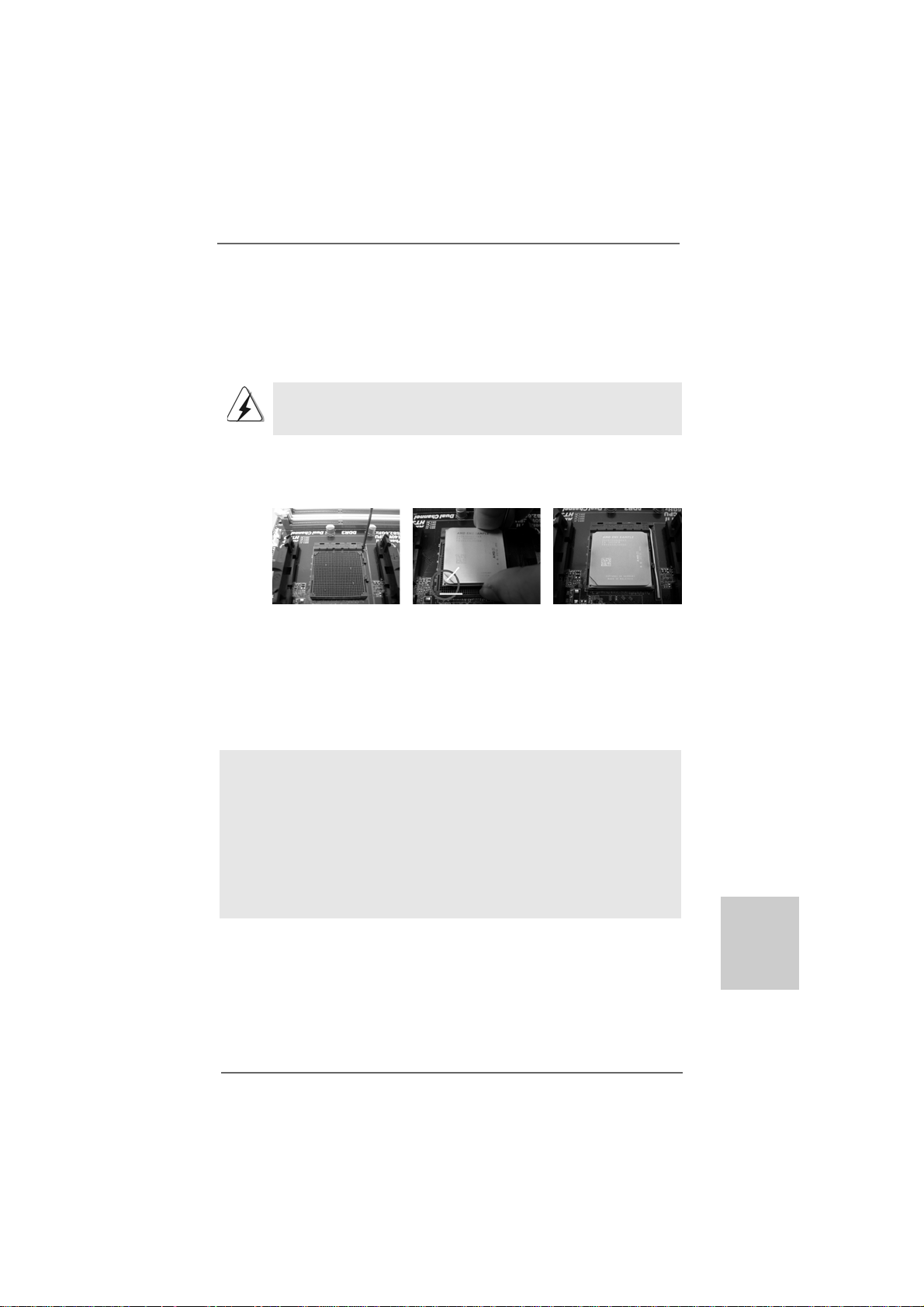
Step 1. Unlock the socket by lifting the lever up to a 90
o
angle.
Step 2. Position the CPU directly above the socket such that the CPU corner with
the golden triangle matches the socket corner with a small triangle.
Step 3. Carefully insert the CPU into the socket until it fits in place.
The CPU fits only in one correct orientation. DO NOT force the CPU
into the socket to avoid bending of the pins.
Step 4. When the CPU is in place, press it firmly on the socket while you push
down the socket lever to secure the CPU. The lever clicks on the side tab
to indicate that it is locked.
Lever 90° Up
CPU Golden Triangle
Socker Corner
Small Triangle
STEP 1:
Lift Up The Socket Lever
2.22.2
Installation of CPU Fan and HeatsinkInstallation of CPU Fan and Heatsink
2.2
Installation of CPU Fan and Heatsink
2.22.2
Installation of CPU Fan and HeatsinkInstallation of CPU Fan and Heatsink
STEP 2 / STEP 3:
Match The CPU Golden Triangle
To The Socket Corner Small
Triangle
STEP 4:
Push Down And Lock
The Socket Lever
After you install the CPU into this motherboard, it is necessary to install a
larger heatsink and cooling fan to dissipate heat. You also need to spray
thermal grease between the CPU and the heatsink to improve heat
dissipation. Make sure that the CPU and the heatsink are securely fastened and in good contact with each other. Then connect the CPU fan to
the CPU FAN connector (CPU_F AN1, see Page 2, No. 6 or CPU_F AN2, see
Page 2, No. 5). For proper installation, please kindly refer to the instruction manuals of the CPU fan and the heatsink.
ASRock 880G Pro3 Motherboard
1313
13
1313
EnglishEnglish
EnglishEnglish
English
Page 14
2.3 Installation of Memory Modules (DIMM)2.3 Installation of Memory Modules (DIMM)
2.3 Installation of Memory Modules (DIMM)
2.3 Installation of Memory Modules (DIMM)2.3 Installation of Memory Modules (DIMM)
This motherboard provides four 240-pin DDR3 (Double Data Rate 3) DIMM slots,
and supports Dual Channel Memory Technology. For dual channel configuration,
you always need to install identical (the same brand, speed, size and chiptype) DDR3 DIMM pair in the slots of the same color. In other words, you have to
install identical DDR3 DIMM pair in Dual Channel A (DDR3_A1 and DDR3_B1;
Blue slots; see p.2 No.8) or identical DDR3 DIMM pair in Dual Channel B
(DDR3_A2 and DDR3_B2; White slots; see p.2 No.9), so that Dual Channel
Memory Technology can be activated. This motherboard also allows you to
install four DDR3 DIMMs for dual channel configuration, and plea se install iden-
tical DDR3 DIMMs in all four slots. You may refer to the Dual Channel Memory
Configuration Table below.
Dual Channel Memory Configurations
DDR3_A1 DDR3_A2 DDR3_B1 DDR3_B2
(Blue Slot) (White Slot) (Blue Slot) (White Slot)
(1) Populated - Populated (2) - Populated - Populated
(3)* Populated Populated Populated Populated
*For the configuration (3), please install identical DDR3 DIMMs in all four
slots.
English
EnglishEnglish
EnglishEnglish
1414
14
1414
1. If you want to install two memory modules, for optimal compatibility
and reliability, it is recommended to install them in the slots of the
same color. In other words, install them either in the set of blue slots
(DDR3_A1 and DDR3_B1), or in the set of white slots (DDR3_A2
and DDR3_B2).
2. If only one memory module or three memory modules are installed
in the DDR3 DIMM slots on this motherboard, it is unable to activate
the Dual Channel Memory T e chnology.
3. If a pair of memory modules is NOT installed in the same Dual
Channel, for example, installing a pair of memory modules in
DDR3_A1 and DDR3_A2, it is unable to activate the Dual Channel
Memory Technology .
4. It is not allowed to install a DDR or DDR2 memory module into
DDR3 slot; otherwise, this motherboard and DIMM may be damaged.
5. If you adopt DDR3 1866/1800/1600 memory modules on this
motherboard, it is recommended to install them on DDR3_A2 and
DDR3_B2 slots.
ASRock 880G Pro3 Motherboard
Page 15
Installing a DIMMInstalling a DIMM
Installing a DIMM
Installing a DIMMInstalling a DIMM
Please make sure to disconnect power supply before adding or
removing DIMMs or the system components.
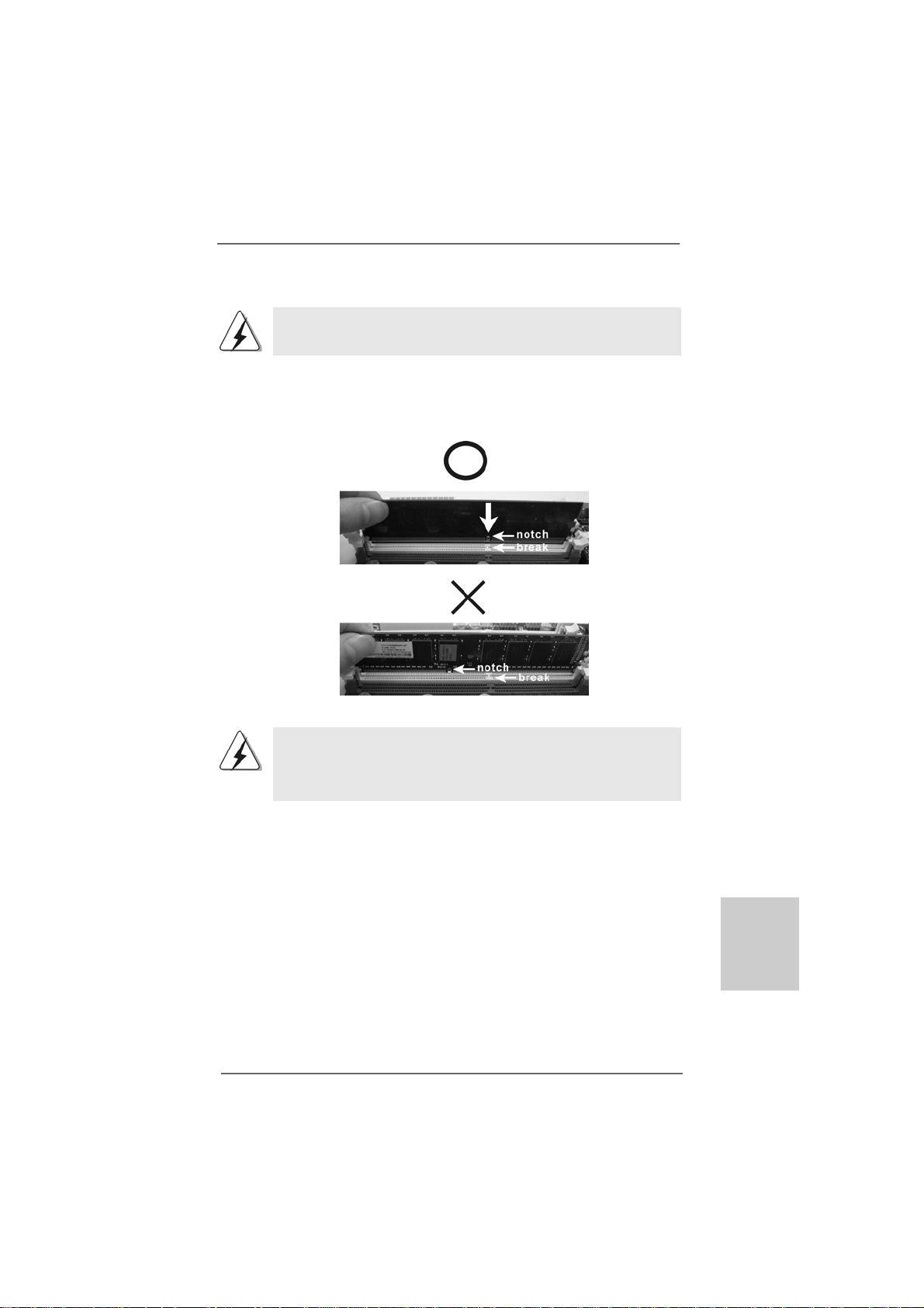
Step 1. Unlock a DIMM slot by pressing the retaining clips outward.
Step 2. Align a DIMM on the slot such that the notch on the DIMM matches the brea k
on the slot.
The DIMM only fits in one correct orientation. It will cause permanent
damage to the motherboard and the DIMM if you force the DIMM into the
slot at incorrect orientation.
Step 3. Firmly insert the DIMM into the slot until the retaining clips at both ends fully
snap back in place and the DIMM is properly seated.
ASRock 880G Pro3 Motherboard
1515
15
1515
EnglishEnglish
EnglishEnglish
English
Page 16
English
EnglishEnglish
EnglishEnglish
2.4 Expansion Slots (PCI and PCI Express Slots)2.4 Expansion Slots (PCI and PCI Express Slots)
2.4 Expansion Slots (PCI and PCI Express Slots)
2.4 Expansion Slots (PCI and PCI Express Slots)2.4 Expansion Slots (PCI and PCI Express Slots)
There are 3 PCI slots and 3 PCI Express slots on this motherboard.
PCI Slots: PCI slots are used to install expansion cards that have the 32-bit PCI
interface.
PCIE Slots:
PCIE1 (PCIE x1 slot; White) is used for PCI Express cards with x1 lane
width cards, such as Gigabit LAN card and SATA2 card.
PCIE2 (PCIE x16 slot; Blue) is used for PCI Express x16 lane width
graphics cards, or used to install PCI Express graphics cards to
support CrossFireXTM function.
PCIE3 (PCIE x16 slot; Blue) is used for PCI Express x4 lane width
cards, or used to install PCI Express graphics cards to support
CrossFireXTM function.
1. In single VGA card mode, it is recommended to install a PCI Express
x16 graphics card on PCIE2 slot.
2. In CrossFireXTM mode, please install PCI Express x16 graphics cards
on PCIE2 and PCIE3 slots.
3. Please connect a chassis fan to motherboard chassis fan connector
(CHA_FAN1, CHA_FAN2 or CHA_FAN3) when using multiple
graphics cards for better thermal environment.
Installing an expansion cardInstalling an expansion card
Installing an expansion card
Installing an expansion cardInstalling an expansion card
Step 1. Before installing the expansion card, please make sure that the power
supply is switched off or the power cord is unplugged. Please read the
documentation of the expansion card and make necessary hardware
settings for the card before you start the installation.
Step 2. Remove the system unit cover (if your motherboard is already installed in
a chassis).
Step 3. Remove the bracket facing the slot that you intend to use. Keep the
screws for later use.
Step 4. Align the card connector with the slot and press firmly until the card is
completely seated on the slot.
Step 5. Fasten the card to the chassis with screws.
Step 6. Replace the system cover.
1616
16
1616
ASRock 880G Pro3 Motherboard
Page 17
2.5 Dual Monitor and Surround Display Features2.5 Dual Monitor and Surround Display Features
2.5 Dual Monitor and Surround Display Features
2.5 Dual Monitor and Surround Display Features2.5 Dual Monitor and Surround Display Features
Dual Monitor Feature
This motherboard supports dual monitor feature. With the internal VGA output
support (DVI-D, D-Sub and HDMI), you can easily enjoy the benefits of dual monitor
feature without installing any add-on VGA card to this motherboard. This
motherboard also provides independent display controllers for DVI-D, D-Sub and
HDMI to support dual VGA output so that DVI-D, D-sub and HDMI can drive same or
different display contents.
To enable dual monitor feature, please follow the below steps:
1. Connect DVI-D monitor cable to VGA/DVI-D port on the I/O panel, connect D-Sub
monitor cable to VGA/D-Sub port on the I/O panel, or connect HDMI monitor
cable to HDMI port on the I/O panel.
VGA/D-Sub port
VGA/DVI-D port
2. If you have installed onboard VGA driver from our support CD to your system
already, you can freely enjoy the benefits of dual monitor function after your
system boots. If you haven’t installed onboard VGA driver yet, please install
onboard VGA driver from our support CD to your system and restart your
computer. Then you can start to use dual monitor function on this motherboard.
1. DVI-D and HDMI ports cannot function at the same time. When one of
them is enabled, the other one will be disabled.
2. When you playback HDCP-protected video from Blu-ray (BD) or
HD-DVD disc, the content will be displayed only in one of the two
monitors instead of both monitors.
ASRock 880G Pro3 Motherboard
HDMI port
1717
17
1717
EnglishEnglish
EnglishEnglish
English
Page 18

Surround Display Feature
This motherboard supports surround display upgrade. With the internal VGA
output support (DVI-D, D-Sub and HDMI) and external add-on PCI Express VGA
cards, you can easily enjoy the benefits of surround display feature.
Please refer to the following steps to set up a surround display environment:
1. Install the ATITM PCI Express V GA cards on PCIE2 and PCIE3 slots. Please
refer to page 16 for proper expansion card installation procedures for details.
2. Connect DVI-D monitor cable to VGA/DVI-D port on the I/O panel, connect D-Sub
monitor cable to VGA/D-Sub port on the I/O panel, or connect HDMI monitor
cable to HDMI port on the I/O panel. Then connect other monitor cables to the
corresponding connectors of the add-on PCI Express VGA cards on PCIE2
and PCIE3 slots.
3. Boot your system. Press <F2> to enter UEFI setup. Enter “Share Memory”
option to adjust the memory capability to [32MB], [64MB], [128MB] [256MB] or
[512MB] to enable the function of VGA/D-sub. Please make sure that the value
you select is less than the total capability of the system memory. If you do not
adjust the UEFI setup, the default value of “Share Memory”, [Auto], will disable
VGA/D-Sub function when the add-on VGA card is inserted to this
motherboard.
4. Install the onboard VGA driver and the add-on PCI Express VGA card driver to
your system. If you have installed the drivers already, there is no need to install
them again.
5. Set up a multi-monitor display.
English
EnglishEnglish
EnglishEnglish
1818
18
1818
For Windows® XP / XP 64-bit OS:
Right click the desktop, choose “Properties”, and select the “Settings” tab
so that you can adjust the parameters of the multi-monitor according to the
steps below.
A. Click the “Identify” button to display a large number on each monitor.
B. Right-click the display icon in the Display Properties dialog that you wish
to be your primary monitor, and then select “Primary”. When you use
multiple monitors with your card, one monitor will always be Primary,
and all additional monitors will be designated as Secondary.
C. Select the display icon identified by the number 2.
D. Click “Extend my Windows desktop onto this monitor”.
E. Right-click the display icon and select “Attached”, if necessary.
F. Set the “Screen Resolution” and “Color Quality” as appropriate for the
second monitor. Click “Apply” or “OK” to apply these new values.
G. Repeat steps C through E for the diaplay icon identified by the number
one, two, three, four, five and six.
ASRock 880G Pro3 Motherboard
Page 19

For Windows® 7 / 7 64-bit / VistaTM / VistaTM 64-bit OS:
Right click the desktop, choose “Personalize”, and select the “Display
Settings” tab so that you can adjust the parameters of the multi-monitor
according to the steps below.
A. Click the number ”2” icon.
B. Click the items “This is my main monitor” and “Extend the desktop onto
this monitor”.
C. Click “OK” to save your change.
D. Repeat steps A through C for the display icon identified by the number
three, four, five and six.
6. Use Surround Display. Click and drag the display icons to positions representing
the physical setup of your monitors that you would like to use. The placement
of display icons determines how you move items from one monitor to another.
HDCP Function
HDCP function is supported on this motherboard. To use HDCP
function with this motherboard, you need to adopt the monitor that
supports HDCP function as well. Therefore, you can enjoy the
superior display quality with high-definition HDCP encryption
contents. Please refer to below instruction for more details about
HDCP function.
What is HDCP?
HDCP stands for High-Bandwidth Digital Content Protection, a
specification developed by Intel® for protecting digital entertainment
content that uses the DVI interface. HDCP is a copy protection
scheme to eliminate the possibility of intercepting digital data
midstream between the video source, or transmitter - such as a
computer, DVD player or set-top box - and the digital display, or
receiver - such as a monitor, television or projector. In other words,
HDCP specification is designed to protect the integrity of content as it
is being transmitted.
Products compatible with the HDCP scheme such as DVD players,
satellite and cable HDTV set-top-boxes, as well as few entertainment PCs requires a secure connection to a compliant display. Due
to the increase in manufacturers employing HDCP in their equipment,
it is highly recommended that the HDTV or LCD monitor you purchase
is compatible.
ASRock 880G Pro3 Motherboard
1919
19
1919
EnglishEnglish
EnglishEnglish
English
Page 20
TMTM
TM
2.62.6
2.6
2.62.6
This motherboard supports ATITM Hybrid CrossFireXTM feature. ATITM Hybrid
CrossFireXTM brings multi-GPU performance capabilities by enabling an AMD 880G
integrated graphics processor and a discrete graphics processor to operate
simultaneously with combined output to a single display for blisteringly-fast frame
rates. Currently, ATITM Hybrid CrossFireXTM Technology is only supported with
Windows® Vista
ATITM Hybrid CrossFireXTM may be supported with Windows® XP OS.
TMTM
AA
TITI
Hybrid CrossF Hybrid CrossF
A
TI
Hybrid CrossF
AA
TITI
Hybrid CrossF Hybrid CrossF
TM
/ 7 OS, and is not available with Windows® XP OS. In the future,
TMTM
TM
TMTM
ireXireX
Operation Guide Operation Guide
ireX
Operation Guide
ireXireX
Operation Guide Operation Guide
English
EnglishEnglish
EnglishEnglish
What does an ATITM Hybrid CrossFireXTM system include?
An ATITM Hybrid CrossFireXTM system includes an ATITM RadeonTM 2400 or ATI
RadeonTM 3450 series graphics processor and a motherboard based on an AMD
880G integrated chipset, all operating in a Windows® VistaTM / 7 environment. Please
refer to below PCI Express graphics card support list for ATITM Hybrid CrossFireXTM.
For the future update of more compatible PCI Express graphics cards, please visit
our website for further information.
Vendor Chipset Model Driver
A TI RADEON HD2400XT POWERCOLOR HD2400 XT Support CD 8.71
256MB DDR3
RADEON HD3450 POWERCOLOR AX3450 Support CD 8.71
256MD2-S
TMTM
TM
Enjoy the benefit of AEnjoy the benefit of A
Enjoy the benefit of A
Enjoy the benefit of AEnjoy the benefit of A
Step 1. Install one compatible PCI Express graphics card to PCIE2 slot (blue). For
the proper installation procedures, please refer to section “Expansion Slots”.
Step 2. Connect the monitor cable to the correspondent connector on the PCI
Express graphics card on PCIE2 slot.
Step 3. Boot your system. Press <F2> to enter UEFI setup. Enter “Advanced”
screen, and enter “North Bridge Configuration”. Then set the option “Surround View” to [Enabled].
Step 4. Boot into OS. Please remove the ATITM driver if you have any VGA driver
installed in your system.
Step 5. Install the onboard VGA driver from our support CD to your system for both
the onboard VGA and the discrete graphics card.
Step 6. Restart your computer. Then you will find “ATI Catalyst Control Center” on
your Windows® taskbar.
TMTM
TITI
Hybrid CrossF Hybrid CrossF
TI
Hybrid CrossF
TITI
Hybrid CrossF Hybrid CrossF
ireXireX
ireX
ireXireX
TMTM
TM
TMTM
TM
2020
20
2020
ATI Catalyst Control Center
ASRock 880G Pro3 Motherboard
Page 21
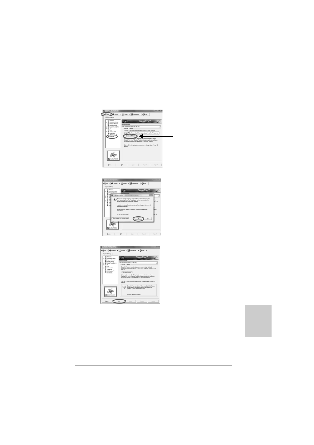
Step 7. Double-click “ATI Catalyst Control Center”. Click “V iew”, click “CrossFireTM”,
and then select the option “Enable CrossFireTM”.
View
CrossFire
TM
Step 8. Click “Yes” to continue.
Step 9. Click “OK” to save your change.
Enable CrossFire
TM
Step 10. Reboot your system. Then you can freely enjoy the benefit of Hybrid
TM
CrossFireXTM feature.
* Hybrid CrossFireXTM appearing here is a registered trademark of ATITM Technologies Inc.,
and is used only for identification or explanation and to the owners’ benefit, without intent to
infringe.
* For further information of ATITM Hybrid CrossFireXTM technology, please check AMD website
for up dates and details.
ASRock 880G Pro3 Motherboard
2121
21
2121
EnglishEnglish
EnglishEnglish
English
Page 22
TMTM
TM
2.72.7
CrossFireXCrossFireX
2.7
CrossFireX
2.72.7
CrossFireXCrossFireX
This motherboard supports CrossFireXTM and Quad CrossFireXTM feature.
CrossFireXTM technology offers the most advantageous means available of combining
multiple high performance Graphics Proce ssing U nits (GPU) in a single PC. Combining
a range of different operating modes with intelligent software design and an innovative
interconnect mechanism, CrossFireXTM enables the highest possible level of
performance and image quality in any 3D application. Currently CrossFireXTM feature
is supported with Windows® XP with Service Pack 2 / VistaTM / 7 OS. Quad
CrossFireX
check AMD website for ATITM CrossFireXTM driver updates.
2.7.1 Graphics Card Setup2.7.1 Graphics Card Setup
2.7.1 Graphics Card Setup
2.7.1 Graphics Card Setup2.7.1 Graphics Card Setup
TM
1. If a customer incorrectly configures their system they will not see the
performance benefits of CrossFireXTM. All three CrossFireXTM components, a
CrossFireXTM Ready graphics card, a CrossFireXTM Ready motherboard and a
CrossFireXTM Edition co-processor graphics card, must be installed correctly to
benefit from the CrossFireXTM multi-GPU platform.
2. If you pair a 12-pipe CrossFireXTM Edition card with a 16-pipe card, both cards
will operate as 12-pipe cards while in CrossFireXTM mode.
TMTM
and Quad CrossFireX and Quad CrossFireX
and Quad CrossFireX
and Quad CrossFireX and Quad CrossFireX
feature are supported with Windows® VistaTM / 7 OS only. Please
TMTM
TM
TMTM
Operation Guide Operation Guide
Operation Guide
Operation Guide Operation Guide
English
EnglishEnglish
EnglishEnglish
2222
22
2222
Different CrossFireXTM cards may require different methods to enable CrossFireX
feature. In below procedures, we use Radeon HD 3870 as the example graphics card.
For other CrossFireXTM cards that ATITM has released or will release in the future, please
refer to ATITM graphics card manuals for detailed installation guide.
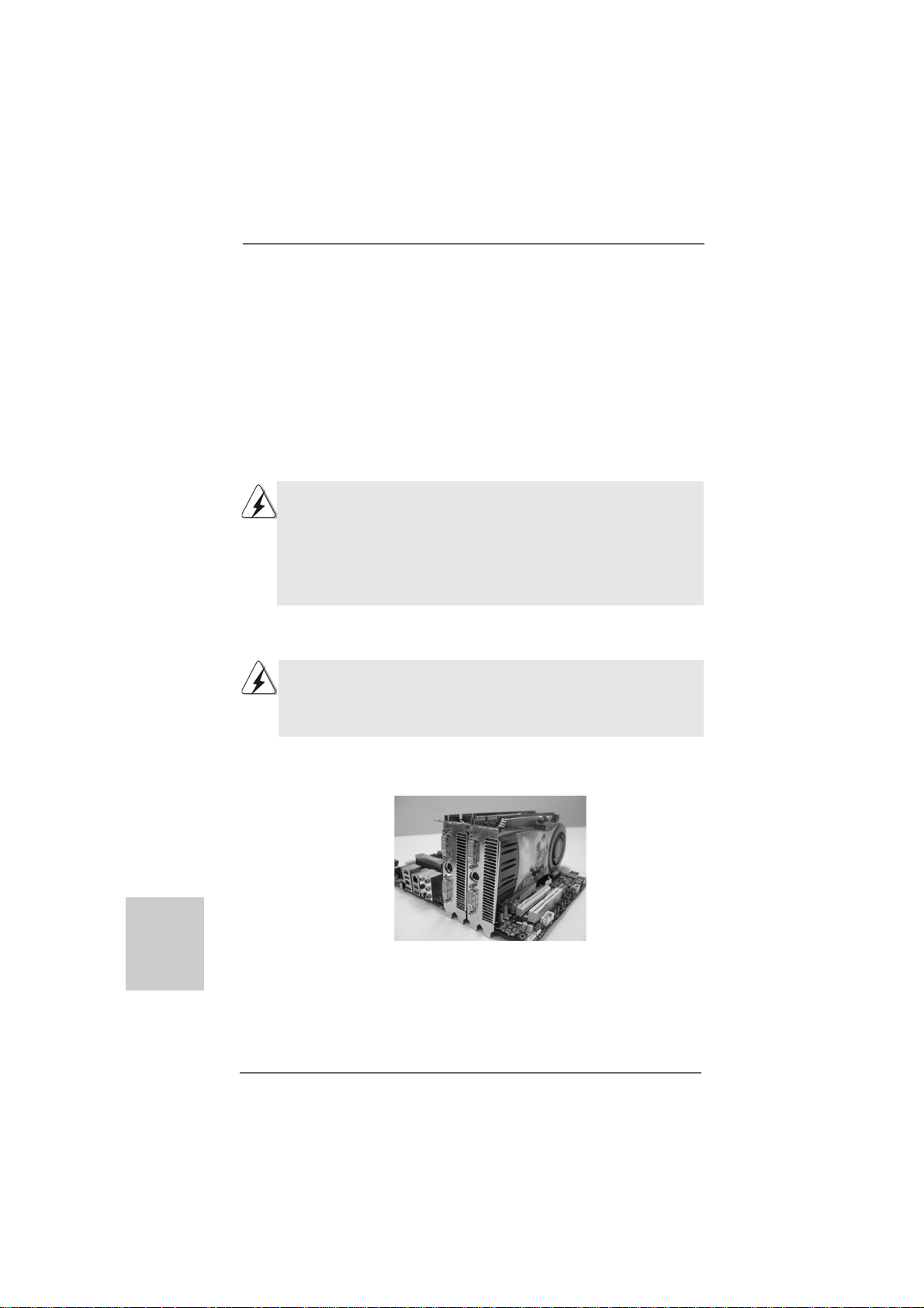
Step 1. I n sert one Radeon graphics card into PCIE2 slot and the other Radeon
graphics card to PCIE3 slot. Make sure that the cards are properly seated
on the slots.
ASRock 880G Pro3 Motherboard
TM
Page 23
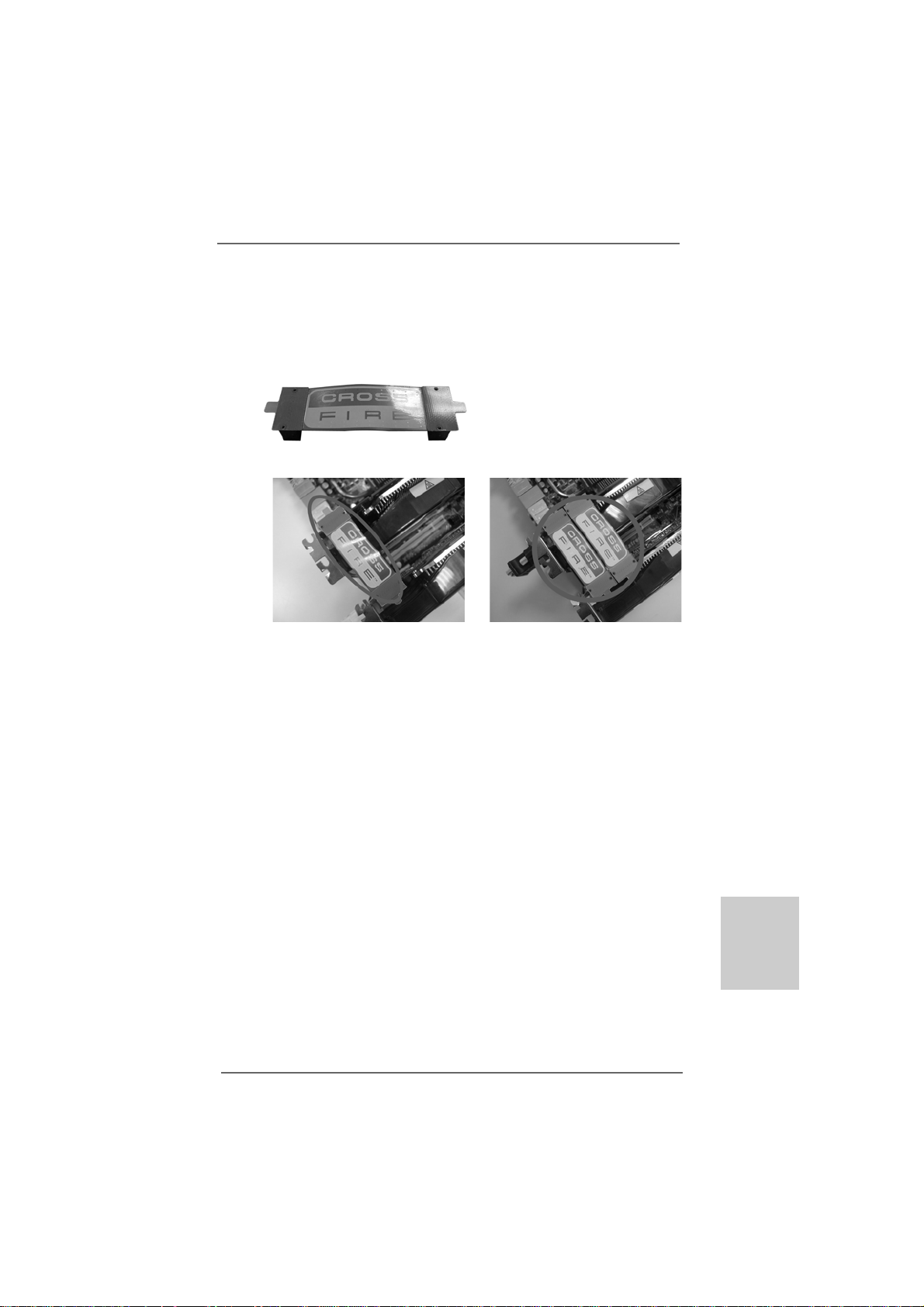
Step 2. Connect two Radeon graphics cards by installing CrossFire Bridge on
CrossFire Bridge Interconnects on the top of Radeon graphics cards.
(CrossFire Bridge is provided with the graphics card you purchase, not
bundled with this motherboard. Please refer to your graphics card vendor
for details.)
CrossFire Bridge
or
Step 3. Connect the D VI monitor ca ble to the DVI connector on the Radeon graphics
card on PCIE2 slot. (You may use the DVI to D-Sub adapter to convert the
DVI connector to D-Sub interface, and then connect the D-Sub monitor
cable to the DVI to D-Sub adapter.)
ASRock 880G Pro3 Motherboard
2323
23
2323
EnglishEnglish
EnglishEnglish
English
Page 24
2.7.2 Driver Installation and Setup2.7.2 Driver Installation and Setup
2.7.2 Driver Installation and Setup
2.7.2 Driver Installation and Setup2.7.2 Driver Installation and Setup
Step 1. Power on your computer and boot into OS.
Step 2. Remove the ATITM driver if you have any VGA driver installed in your syste m.
The Catalyst Uninstaller is an optional download. We recommend using this
utility to uninstall any previously installed Catalyst drivers prior to installation.
Please check AMD website for ATITM driver updates.
Step 3. Install the required drivers to your system.
For Windows® XP OS:
A. ATITM recommends Windows® XP Service Pack 2 or higher to be
installed (If you have Windows® XP Service Pack 2 or higher installed
in your system, there is no need to download it again):
http://www.microsoft.com/windowsxp/sp2/default.mspx
B. You must have Microsoft .NET Framework installed prior to
downloading and installing the CATALYST Control Center. Please
check Microsoft website for details.
For Windows® 7 / VistaTM OS:
Install the CA TALYST Control Center. Please check AMD website for details.
Step 4. Restart your computer.
Step 5. Install the VGA card drivers to your system, and restart your computer.
Then you will find “ATI Catalyst Control Center” on your Windows® taskbar.
ATI Catalyst Control Center
English
EnglishEnglish
EnglishEnglish
2424
24
2424
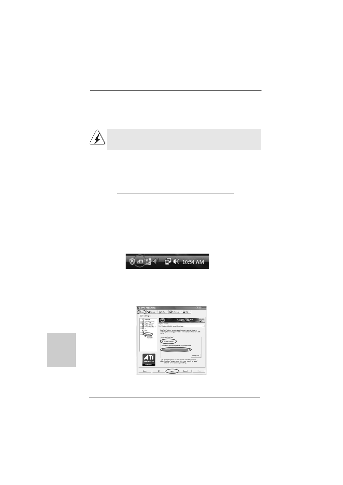
Step 6. Double-click “ATI Catalyst Control Center”. Click “View”, select
“CrossFireXTM”, and then check the item “Enable CrossFireXTM”. Select “2
GPUs” and click “Apply” (if you install two Radeon graphics cards).
ASRock 880G Pro3 Motherboard
Page 25
Although you have selected the option “Enable CrossFireTM”, the CrossFireX
function may not work actually. Your computer will automatically reboot. After
restarting your computer, please confirm whether the option “Enable
CrossFireTM” in “ATI Catalyst Control Center” is selected or not; if not, please
select it again, and then you are able to enjoy the benefit of CrossFireX
feature.
TM
TM
Step 7. You can freely enjoy the benefit of CrossFireXTM or Quad CrossFireX
feature.
* CrossFireXTM appearing here is a registered trademark of ATITM Technologies Inc., and is
used only for identification or explanation and to the owners’ benefit, without intent to infringe.
* For further information of ATITM CrossFireXTM technology, please check AMD website for
updates and details.
TM
ASRock 880G Pro3 Motherboard
2525
25
2525
EnglishEnglish
EnglishEnglish
English
Page 26
2.82.8
Jumpers SetupJumpers Setup
2.8
Jumpers Setup
2.82.8
Jumpers SetupJumpers Setup
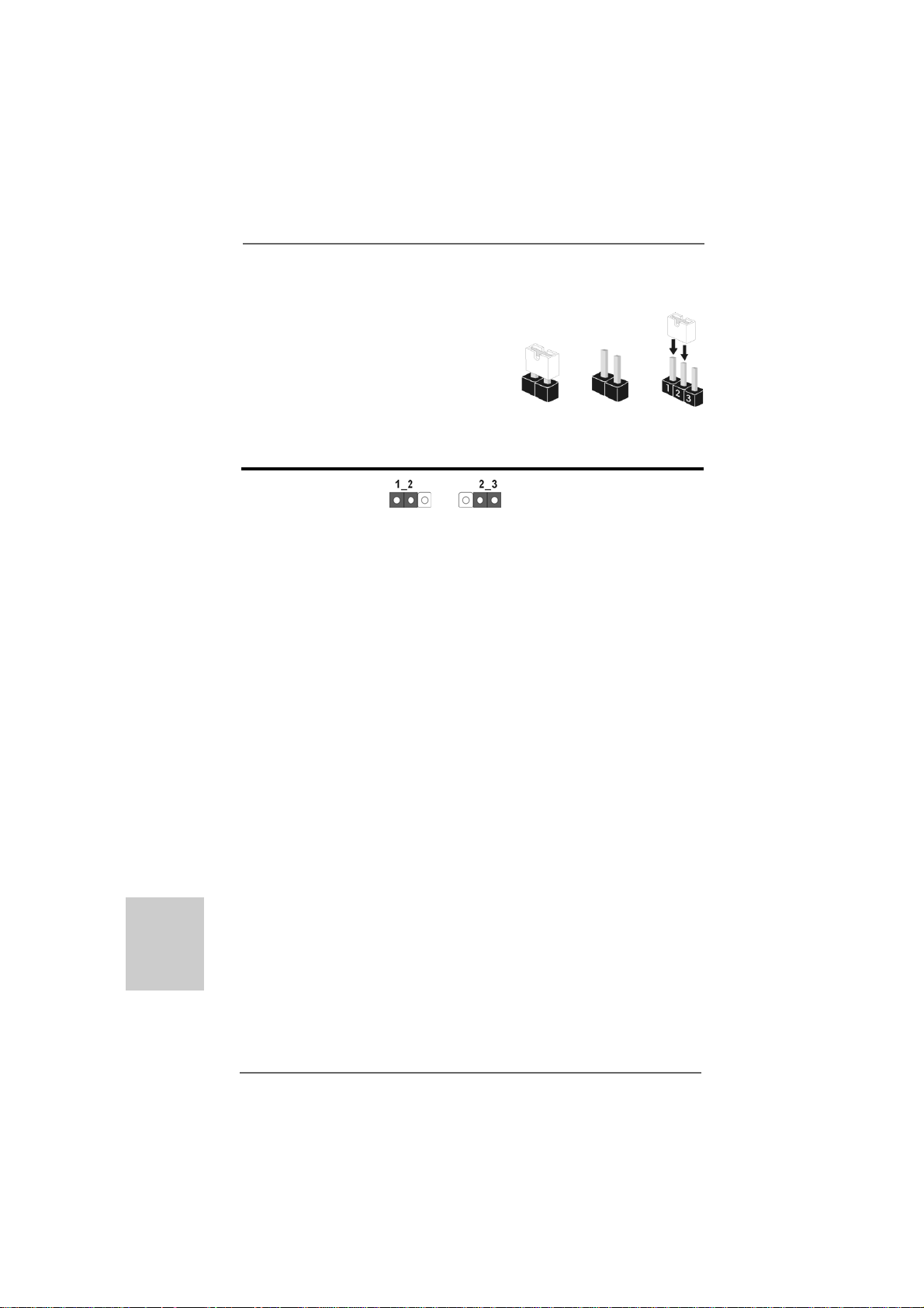
The illustration shows how jumpers are
setup. When the jumper cap is placed on
pins, the jumper is “Short”. If no jumper cap
is placed on pins, the jumper is “Open”. The
illustration shows a 3-pin jumper whose pin1
and pin2 are “Short” when jumper cap is
placed on these 2 pins.
Jumper Setting
Clear CMOS Jumper
(CLRCMOS1)
(see p.2, No. 28)
Note: CLRCMOS1 allows you to clear the data in CMOS. The data in CMOS includes
system setup information such as system password, date, time, and system
setup parameters. To clear and reset the system parameters to default setup,
please turn off the computer and unplug the power cord from the power
supply. After waiting for 15 seconds, use a jumper cap to short pin2 and pin3
on CLRCMOS1 for 5 seconds. However, please do not clear the CMOS right
after you update the BIOS. If you need to clear the CMOS when you just finish
updating the BIOS, you must boot up the system first, and then shut it down
before you do the clear-CMOS action.
Clear CMOSDefault
OpenShort
English
EnglishEnglish
EnglishEnglish
2626
26
2626
ASRock 880G Pro3 Motherboard
Page 27
2.9 Onboard Headers and Connectors2.9 Onboard Headers and Connectors
2.9 Onboard Headers and Connectors
2.9 Onboard Headers and Connectors2.9 Onboard Headers and Connectors
Onboard headers and connectors are NOT jumpers. Do NOT place
jumper caps over these headers and connectors. Placing jumper caps
over the headers and connectors will cause permanent damage of the
motherboard!
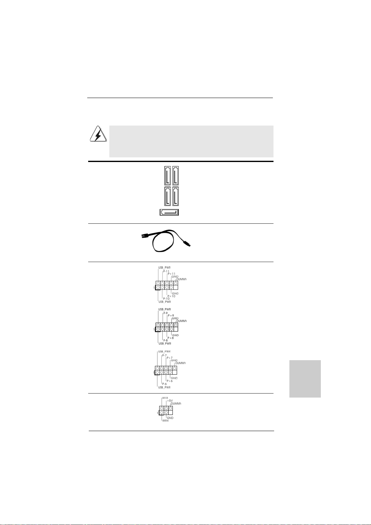
Serial A TA3 Connectors The se five Serial ATA3
(SAT AIII_1: see p.2, No. 17) (SATA3) connectors support
(SAT AIII_2: see p.2, No. 16) SATA data cables for internal
(SAT AIII_3: see p.2, No. 14) storage devices. The current
(SAT AIII_4: see p.2, No. 15) SATA3 interface allows up to
(SAT A3_5: see p.2, No. 18) 6.0 Gb/s data transfer rate.
SAT AIII_1 SA T AIII_3
SAT AIII_2 SA T AIII_4
SAT A3_5
Serial A TA (SA TA) Either end of the SATA data ca ble
Data Cable can be connected to the SATA3
(Optional) hard disk or the SATA3
connector on this motherboard.
USB 2.0 Headers Besides four default USB 2.0
(9-pin USB10_11) ports on the I/O panel, there are
(see p.2 No. 27) three USB 2.0 headers on this
motherboard. Each USB 2.0
header can support two USB
2.0 ports.
(9-pin USB8_9)
(see p.2 No. 29)
(9-pin USB6_7)
(see p.2 No. 30)
Infrared Module Header This header supports an
(5-pin IR1) optional wireless transmitting
(see p.2 No. 32) and receiving infrared module.
ASRock 880G Pro3 Motherboard
2727
27
2727
EnglishEnglish
EnglishEnglish
English
Page 28
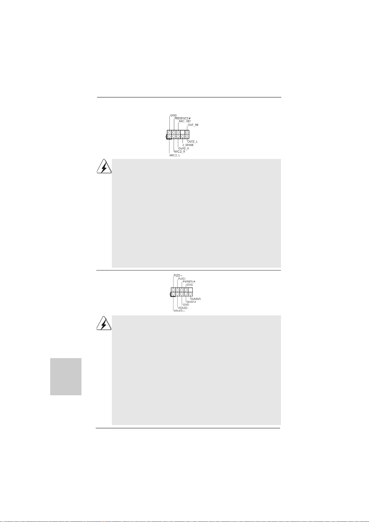
Front Panel Audio Header This is an interface for the front
(9-pin HD_AUDIO1) panel audio cable that allows
(see p.2, No. 34) convenient connection and
control of audio devices.
1. High Definition Audio supports Jack Sensing, but the panel wire on
the chassis must support HDA to function correctly. Please follow the
instruction in our manual and chassis manual to install your system.
2. If you use AC’97 audio panel, please install it to the front panel audio
header as below:
A. Connect Mic_IN (MIC) to MIC2_L.
B. Connect Audio_R (RIN) to OUT2_R and Audio_L (LIN) to OUT2_L.
C. Connect Ground (GND) to Ground (GND).
D. MIC_RET and OUT_RET are for HD audio panel only. You don’t
need to connect them for AC’97 audio panel.
E. To activate the front mic.
For Windows® XP / XP 64-bit OS:
Select “Mixer”. Select “Recorder”. Then click “FrontMic”.
For Windows® 7 / 7 64-bit / VistaTM / VistaTM 64-bit OS:
Go to the "FrontMic" Tab in the Realtek Control panel. Adjust
“Recording Volume”.
System Panel Header This header accommodates
(9-pin PANEL1) several system front panel
(see p.2 No. 22) functions.
English
EnglishEnglish
EnglishEnglish
2828
28
2828
Connect the power switch, reset switch and system status indicator on
the chassis to this header according to the pin assignments below. Note
the positive and negative pins before connecting the cables.
PWRBTN (Power Switch):
Connect to the power switch on the chassis front panel. You may
configure the way to turn off your system using the power switch.
RESET (Reset Switch):
Connect to the reset switch on the chassis front panel. Press the reset
switch to restart the computer if the computer freezes and fails to
perform a normal restart.
PLED (System Power LED):
Connect to the power status indicator on the chassis front panel. The LED
is on when the system is operating. The LED keeps blinking when the
sys-tem is in S1 sleep state. The LED is off when the system is in S3/S4
sleep state or powered off (S5).
ASRock 880G Pro3 Motherboard
Page 29
HDLED (Hard Drive Activity LED):
Connect to the hard drive activity LED on the chassis front panel. The
LED is on when the hard drive is reading or writing data.
The front panel design may differ by chassis. A front panel module
mainly consists of power switch, reset switch, power LED, hard drive
activity LED, speaker and etc. When connecting your chassis front panel
module to this header, make sure the wire assignments and the pin
assign-ments are matched correctly.
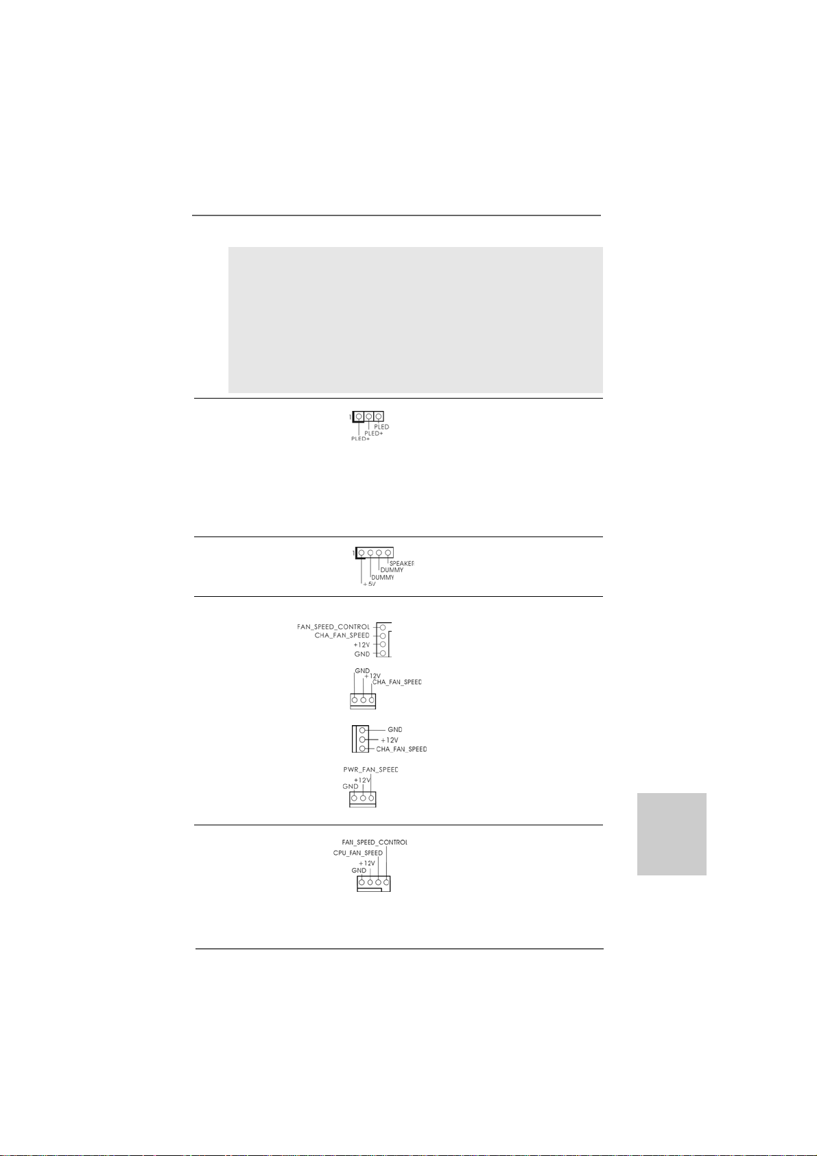
Power LED Header Please connect the chassis
(3-pin PLED1) power LED to this header to
(see p.2 No. 21) indicate system power status.
The LED is on when the system
is operating. The LED keeps
blinking in S1 state. The LED is
off in S3/S4 state or S5 state
(power off).
Chassis Speaker Header Please connect the chassis
(4-pin SPEAKER 1) speaker to this header.
(see p.2 No. 20)
Chassis and Power Fan Connectors Please connect the fan cables
(4-pin CHA_FAN1) to the fan connectors and
(see p.2 No. 40) match the black wire to the
ground pin. CHA_FAN1/2/3 fan
(3-pin CHA_FAN2) speed can be controlled through
(see p.2 No. 7) UEFI or AXTU utility.
(3-pin CHA_FAN3)
(see p.2 No. 12)
(3-pin PWR_FAN1)
(see p.2 No. 2)
CPU Fan Connectors Please connect the CPU fan
(4-pin CPU_FAN1) cable to the connector and
(see p.2 No. 6) match the black wire to the
1 2 3 4
ground pin.
ASRock 880G Pro3 Motherboard
2929
29
2929
EnglishEnglish
EnglishEnglish
English
Page 30
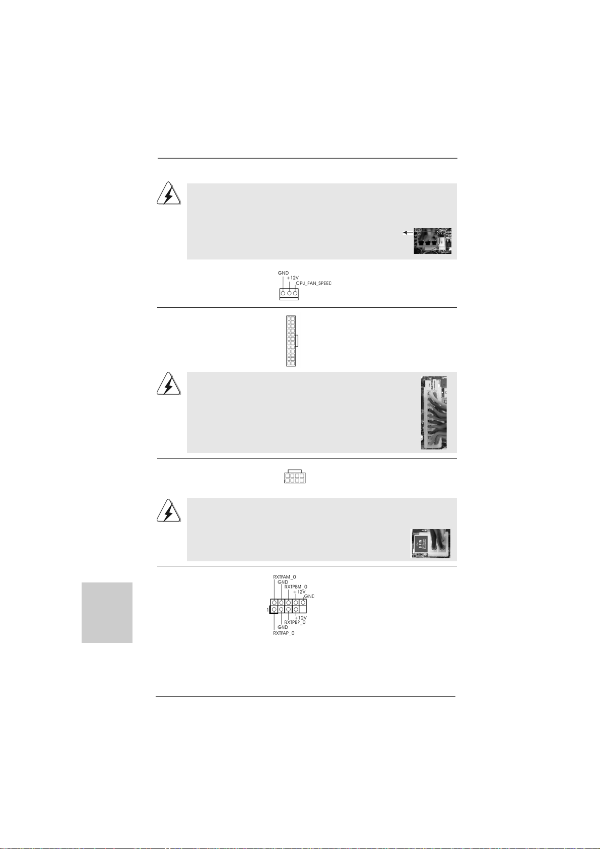
Though this motherboard provides 4-Pin CPU fan (Quiet Fan) support, the 3-Pin
CPU fan still can work successfully even without the fan speed control function.
If you plan to connect the 3-Pin CPU fan to the CPU fan connector on this
motherboard, please connect it to Pin 1-3.
Pin 1-3 Connected
3-Pin Fan Installation
(3-pin CPU_FAN2)
(see p.2 No. 5)
English
EnglishEnglish
EnglishEnglish
ATX Power Connector Please connect an ATX power
(24-pin ATXPW R1) supply to this connector.
(see p.2 No. 10)
Though this motherboard provides 24-pin ATX power connector,
it can still work if you adopt a traditional 20-pin ATX power supply.
12 124
13
12
To use the 20-pin ATX power supply, please plug your power
supply along with Pin 1 and Pin 13.
20-Pin A TX Power Supply Installation
ATX 12V Power Connector Please connect an ATX 12V
(8-pin A TX12V1) power supply to this connector.
(see p.2 No. 1)
8 5
4 1
1
Though this motherboard provides 8-pin ATX 12V power connector, it can still work
if you adopt a traditional 4-pin ATX 12V power supply. To use the 4-pin ATX power
supply, please plug your power supply along with Pin 1 and Pin 5.
4-Pin ATX 12V Power Supply Installation
8 5
4 1
IEEE 1394 Header Besides one default IEEE 1394
(9-pin FRONT_1394) port on the I/O panel, there is one
(see p.2 No. 25) IEEE 1394 header
(FRONT_1394) on this
motherboard. This IEEE 1394
header cansupport one IEEE
1394 port.
24
13
3030
30
3030
ASRock 880G Pro3 Motherboard
Page 31

Serial port Header This COM1 header supports a
(9-pin COM1) serial port module.
(see p.2 No.31)
HDMI_SPDIF Header HDMI_SPDIF header, providing
(2-pin HDMI_SPDIF1) SPDIF audio output to HDMI V GA
(see p.2 No. 33) card, allows the system to
connect HDMI Digital TV/
projector/LCD devices. Please
connect the HDMI_SPDIF
connector of HDMI VGA card to
this header.
ASRock 880G Pro3 Motherboard
3131
31
3131
EnglishEnglish
EnglishEnglish
English
Page 32

2.10 Smart Switches2.10 Smart Switches
2.10 Smart Switches
2.10 Smart Switches2.10 Smart Switches
This motherboard has three smart switches: power switch, reset switch and
clear CMOS switch, allowing users to quickly turn on/off or reset the system or
clear the CMOS values.
Power Switch Power Switch is a smart switch,
(PWRBTN) allowing users to quickly turn
(see p.2 No. 24) on/off the system.
Reset Switch Reset Switch is a smart switch,
(RSTBTN) allowing users to quickly reset
(see p.2 No. 23) the system.
RESET
Clear CMOS Switch Clear CMOS Switch is a smart
(CLRCBTN) switch, allowing users to quickly
(see p.3 No. 14) clear the CMOS values
You are not allowed to use Clear CMOS switch function if you set up the system
password. If you want to clear the CMOS values, please clean your system
password in advance or refer to page 26 “Clear CMOS jumper” description
instead.
clr
CMOS
English
EnglishEnglish
EnglishEnglish
3232
32
3232
ASRock 880G Pro3 Motherboard
Page 33

2.11 Dr. Debug2.11 Dr. Debug
2.11 Dr. Debug
2.11 Dr. Debug2.11 Dr. Debug
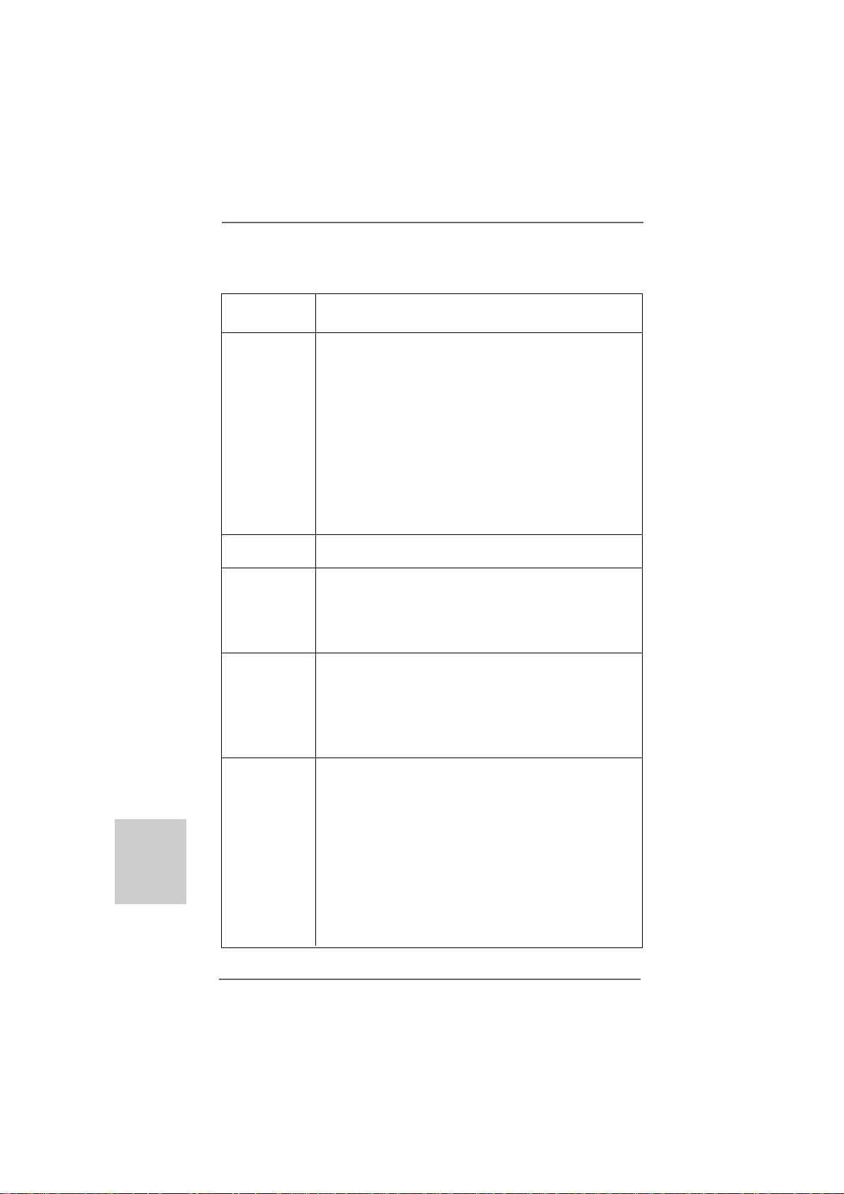
Dr. Debug is used to provide code information, which makes troubleshooting even
easier. Please see the diagrams below for reading the Dr. Debug codes.
Status Code Description
0x00 Not used
0x01 Power on. Reset type detection (soft/hard)
0x02 AP initialization before microcode loading
0x03 North Bridge initialization before microcode loading
0x04 South Bridge initialization before microcode loading
0x05 OEM initialization before microcode loading
0x06 Microcode loading
0x07 AP initialization after microcode loading
0x08 North Bridge initialization after microcode loading
0x09 South Bridge initialization after microcode loading
0x0A OEM initialization after microcode loading
0x0B Cache initialization
0x0C – 0x0D Reserved for future AMI SEC error codes
0x0E Microcode not found
0x0F Microcode not loaded
0x10 PEI Core is started
0x11 Pre-memory CPU initialization is started
0x12 Pre-memory CPU initialization (CPU module specific)
0x13 Pre-memory CPU initialization (CPU module specific)
0x14 Pre-memory CPU initialization (CPU module specific)
0x15 Pre-memory North Bridge initialization is started
0x16 Pre-Memory North Bridge initialization (North Bridge module specific)
0x17 Pre-Memory North Bridge initialization (North Bridge module specific)
0x18 Pre-Memory North Bridge initialization (North Bridge module specific)
0x19 Pre-memory South Bridge initialization is started
0x1A Pre-memory South Bridge initialization (South Bridge module specific)
0x1B Pre-memory South Bridge initialization (South Bridge module specific)
0x1C Pre-memory South Bridge initialization (South Bridge module specific)
0x1D – 0x2A OEM pre-memory initialization codes
0x2B Memory initialization. Serial Presence Detect (SPD) data reading
0x2C Memory initialization. Memory presence detection
0x2D Memory initialization. Programming memory timing information
0x2E Memory initialization. Configuring memory
0x2F Memory initialization (other)
0x30 Reserved for ASL (see ASL Status Codes section below)
0x31 Memory Installed
0x32 CPU post-memory initialization is started
0x33 CPU post-memory initialization. Cache initialization
0x34 CPU post-memory initialization. Application Processor(s) (AP) initialization
0x35 CPU post-memory initialization. Boot Strap Processor (BSP) selection
0x36 CPU post-memory initialization. System Management Mode (SMM)
initialization
ASRock 880G Pro3 Motherboard
3333
33
3333
EnglishEnglish
EnglishEnglish
English
Page 34

English
EnglishEnglish
EnglishEnglish
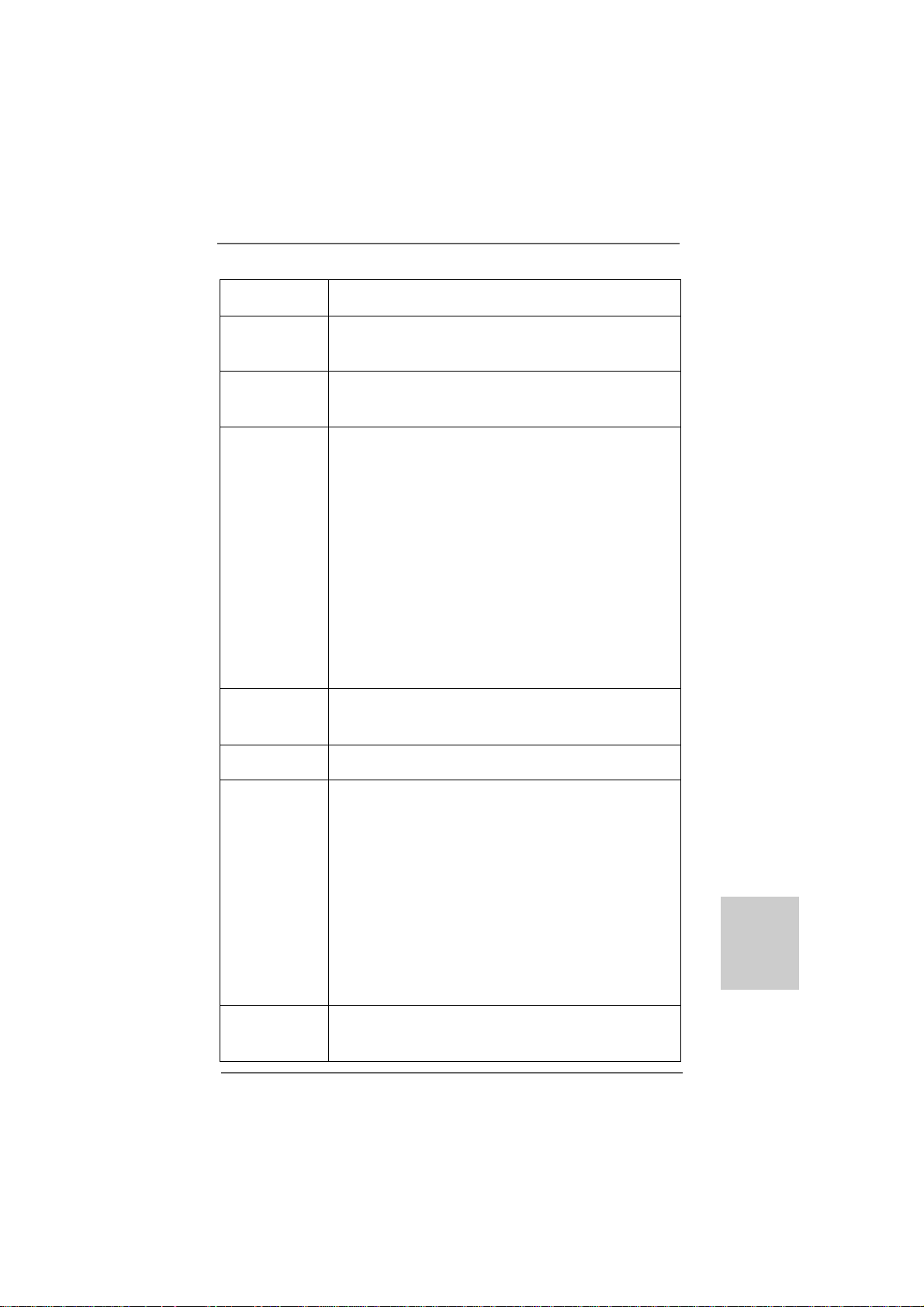
0x37 Post-Memory North Bridge initialization is started
0x38 Post-Memory North Bridge initialization (North Bridge module specific)
0x39 Post-Memory North Bridge initialization (North Bridge module specific)
0x3A Post-Memory North Bridge initialization (North Bridge module specific)
0x3B Post-Memory South Bridge initialization is started
0x3C Post-Memory South Bridge initialization (South Bridge module specific)
0x3D Post-Memory South Bridge initialization (South Bridge module specific)
0x3E Post-Memory South Bridge initialization (South Bridge module specific)
0x3F-0x4E OEM post memory initialization codes
0x4F DXE IPL is started
0x50 Memory initialization error. Invalid memory type or incompatible memory
speed
0x51 Memory initialization error. SPD reading has failed
0x52 Memory initialization error. Invalid memory size or memory modules do not
match
0x53 Memory initialization error. No usable memory detected
0x54 Unspecified memory initialization error
0x55 Memory not installed
0x56 Invalid CPU type or Speed
0x57 CPU mismatch
0x58 CPU self test failed or possible CPU cache error
0x59 CPU micro-code is not found or micro-code update is failed
0x5A Internal CPU error
0x5B reset PPI is not available
0x5C-0x5F Reserved for future AMI error codes
0xE0 S3 Resume is stared (S3 Resume PPI is called by the DXE IPL)
0xE1 S3 Boot Script execution
0xE2 Video repost
0xE3 OS S3 wake vector call
0xE4-0xE7 Reserved for future AMI progress codes
0xE8 S3 Resume Failed
0xE9 S3 Resume PPI not Found
0xEA S3 Resume Boot Script Error
0xEB S3 OS Wake Error
0xEC-0xEF Reserved for future AMI error codes
0xF0 Recovery condition triggered by firmware (Auto recovery)
0xF1 Recovery condition triggered by user (Forced recovery)
0xF2 Recovery process started
0xF3 Recovery firmware image is found
0xF4 Recovery firmware image is loaded
0xF5-0xF7 Reserved for future AMI progress codes
0xF8 Recovery PPI is not available
0xF9 Recovery capsule is not found
0xFA Invalid recovery capsule
0xFB – 0xFF Reserved for future AMI error codes
0x60 DXE Core is started
0X61 N VRAM initialization
3434
34
3434
ASRock 880G Pro3 Motherboard
Page 35

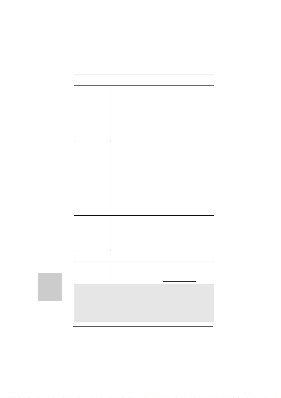
0x62 Installation of the South Bridge Runtime Services
0x63 CPU DXE initialization is started
0x64 CPU DXE initialization (CPU module specific)
0x65 CPU DXE initialization (CPU module specific)
0x66 CPU DXE initialization (CPU module specific)
0x67 CPU DXE initialization (CPU module specific)
0x68 PCI host bridge initialization
0x69 North Bridge DXE initialization is started
0x6A North Bridge DXE SMM initialization is started
0x6B North Bridge DXE initialization (North Bridge module specific)
0x6C North Bridge DXE initialization (North Bridge module specific)
0x6D North Bridge DXE initialization (North Bridge module specific)
0x6E North Bridge DXE initialization (North Bridge module specific)
0x6F North Bridge DXE initialization (North Bridge module specific)
0x70 South Bridge DXE initialization is started
0x71 South Bridge DXE SMM initialization is started
0x72 South Bridge devices initialization
0x73 South Bridge DXE Initialization (South Bridge module specific)
0x74 South Bridge DXE Initialization (South Bridge module specific)
0x75 South Bridge DXE Initialization (South Bridge module specific)
0x76 South Bridge DXE Initialization (South Bridge module specific)
0x77 South Bridge DXE Initialization (South Bridge module specific)
0x78 ACPI module initialization
0x79 CSM initialization
0x7A – 0x7F Reserved for future AMI DXE codes
0x80 – 0x8F OEM DXE initialization codes
0x90 Boot Device Selection (BDS) phase is started
0x91 Driver connecting is started
0x92 PCI Bus initialization is started
0x93 PCI Bus Hot Plug Controller Initialization
0x94 PCI Bus Enumeration
0x95 PCI Bus Request Resources
0x96 PCI Bus Assign Resources
0x97 Console Output devices connect
0x98 Console input devices connect
0x99 Super IO Initialization
0x9A USB initialization is started
0x9B USB Reset
0x9C USB Detect
0x9D USB Enable
0x9E – 0x9F Reserved for future AMI codes
0xA0 IDE initialization is started
0xA1 IDE Reset
0xA2 IDE Detect
0xA3 IDE Enable
0xA4 SCSI initialization is started
0xA5 SCSI Reset
EnglishEnglish
EnglishEnglish
English
ASRock 880G Pro3 Motherboard
3535
35
3535
Page 36

0xA6 SCSI Detect
0xA7 SCSI Enable
0xA8 Setup Verifying Password
0xA9 Start of Setup
0xAA Reserved for ASL (see ASL Status Codes section below)
0xAB Setup Input Wait
0xAC Reserved for ASL (see ASL Status Codes section below)
0xAD Ready To Boot event
0xAE Legacy Boot event
0xAF Exit Boot Services event
0xB0 Runtime Set Virtual Address MAP Begin
0xB1 Runtime Set Virtual Address MAP End
0xB2 Legacy Option ROM Initialization
0xB3 System Reset
0xB4 USB hot plug
0xB5 PCI bus hot plug
0xB6 Clean-up of NVRAM
0xB7 Configuration Reset (reset of NVRAM settings)
0xB8 – 0xBF Reserved for future AMI codes
0xC0 – 0xCF OEM BDS initialization codes
0xD0 CPU initialization error
0xD1 North Bridge initialization error
0xD2 South Bridge initialization error
0xD3 Some of the Architectural Protocols are not available
0xD4 PCI resource allocation error. Out of Resources
0xD5 No Space for Legacy Option ROM
0xD6 No Console Output Devices are found
0xD7 No Console Input Devices are found
0xD8 Invalid password
0xD9 Error loading Boot Option (LoadImage returned error)
0xDA Boot Option is failed (StartImage returned error)
0xDB Flash update is failed
0xDC Reset protocol is not available
English
EnglishEnglish
EnglishEnglish
3636
36
3636
ASRock 880G Pro3 Motherboard
Page 37

2.122.12
Driver Installation GuideDriver Installation Guide
2.12
Driver Installation Guide
2.122.12
Driver Installation GuideDriver Installation Guide
To install the drivers to your system, please insert the support CD to your optical
drive first. Then, the drivers compatible to your system can be auto-detected and
listed on the support CD driver page. Please follow the order from up to bottom
side to install those required drivers. Therefore, the drivers you install can work
properly.
®®
®
2.132.13
Installing WindowsInstalling Windows
2.13
Installing Windows
2.132.13
Installing WindowsInstalling Windows
TMTM
TM
TMTM
VistaVista
Vista
VistaVista
If you want to install Windows® 7 / 7 64-bit / VistaTM / VistaTM 64-bit / XP / XP 64-bit on
your SATA3 HDDs with RAID functions, please refer to the document at the following
path in the Support CD for detailed procedures:
..\ RAID Installation Guide
2.142.14
Installing WindowsInstalling Windows
2.14
Installing Windows
2.142.14
Installing WindowsInstalling Windows
VistaVista
Vista
VistaVista
If you want to install Windows® 7 / 7 64-bit / VistaTM / VistaTM 64-bit / XP / XP 64-bit OS
on your SATA3 HDDs without RAID functions, please follow below procedures
according to the OS you install.
2.14.1 Installing Windows2.14.1 Installing Windows
2.14.1 Installing Windows
2.14.1 Installing Windows2.14.1 Installing Windows
Functions Functions
Functions
Functions Functions
If you want to install Windows® XP / XP 64-bit on your SATA3 HDDs without RAID
functions, please follow below steps.
Using SATA3 HDDs without NCQ and Hot Plug functions (IDE mode)
STEP 1: Set up UEFI.
A. Enter UEFI SETUP UTILITY Advanced screen Storage
Configuration.
B. Set the “SATA Mode” option to [IDE].
STEP 2: Install Windows® XP / XP 64-bit OS on your system.
64-bit / XP / XP 64-bit With RAID Functions 64-bit / XP / XP 64-bit With RAID Functions
64-bit / XP / XP 64-bit With RAID Functions
64-bit / XP / XP 64-bit With RAID Functions 64-bit / XP / XP 64-bit With RAID Functions
TMTM
TM
TMTM
64-bit / XP / XP 64-bit Without RAID Functions 64-bit / XP / XP 64-bit Without RAID Functions
64-bit / XP / XP 64-bit Without RAID Functions
64-bit / XP / XP 64-bit Without RAID Functions 64-bit / XP / XP 64-bit Without RAID Functions
®®
7 / 7 64-bit / Vista 7 / 7 64-bit / Vista
7 / 7 64-bit / Vista
7 / 7 64-bit / Vista 7 / 7 64-bit / Vista
®®
®
®®
7 / 7 64-bit / Vista 7 / 7 64-bit / Vista
7 / 7 64-bit / Vista
7 / 7 64-bit / Vista 7 / 7 64-bit / Vista
®®
®
®®
XP / XP 64-bit Without RAID XP / XP 64-bit Without RAID
XP / XP 64-bit Without RAID
XP / XP 64-bit Without RAID XP / XP 64-bit Without RAID
TMTM
TM
TMTM
/ /
/
/ /
TMTM
TM
TMTM
/ /
/
/ /
ASRock 880G Pro3 Motherboard
3737
37
3737
EnglishEnglish
EnglishEnglish
English
Page 38

®®
®
2.14.2 Installing Windows2.14.2 Installing Windows
2.14.2 Installing Windows
2.14.2 Installing Windows2.14.2 Installing Windows
TMTM
TM
Vista Vista
Vista
Vista Vista
If you want to install Windows® 7 / 7 64-bit / VistaTM / VistaTM 64-bit on your SATA3
HDDs without RAID functions, please follow below steps.
Using SATA3 HDDs without NCQ and Hot Plug functions (IDE mode)
STEP 1: Set up UEFI.
A. Enter UEFI SETUP UTILITY Advanced screen Storage
Configuration.
B. Set the “SATA Mode” option to [IDE].
STEP 2: Install Windows® 7 / 7 64-bit / VistaTM / VistaTM 64-bit OS on your
system.
Using SATA3 HDDs with NCQ and Hot Plug functions (AHCI mode)
STEP 1: Set up UEFI.
A. Enter UEFI SETUP UTILITY Advanced screen Storage
Configuration.
B. Set the “SATA Mode” option to [AHCI].
STEP 2: Install Windows® 7 / 7 64-bit / VistaTM / VistaTM 64-bit OS on your
system.
2.152.15
Untied Overclocking TUntied Overclocking T
2.15
Untied Overclocking T
2.152.15
Untied Overclocking TUntied Overclocking T
This motherboard supports Untied Overclocking Technology, which means during
overclocking, FSB enjoys better margin due to fixed PCI / PCIE buses. Before you
enable Untied Overclocking function, please enter “Overclock Mode” option of UEFI
setup to set the selection from [Auto] to [Manual]. Therefore, CPU FSB is untied
during overclocking, but PCI / PCIE buses are in the fixed mode so that FSB can
operate under a more stable overclocking environment.
TMTM
64-bit Without RAID Functions 64-bit Without RAID Functions
64-bit Without RAID Functions
64-bit Without RAID Functions 64-bit Without RAID Functions
®®
7 / 7 64-bit / Vista 7 / 7 64-bit / Vista
7 / 7 64-bit / Vista
7 / 7 64-bit / Vista 7 / 7 64-bit / Vista
echnologyechnology
echnology
echnologyechnology
TMTM
TM
TMTM
/ /
/
/ /
English
EnglishEnglish
EnglishEnglish
3838
38
3838
Please refer to the warning on page 8 for the possible overclocking risk
before you apply Untied Overclocking Technology.
ASRock 880G Pro3 Motherboard
Page 39

3. BIOS Information3. BIOS Information
3. BIOS Information
3. BIOS Information3. BIOS Information
The Flash Memory on the motherboard stores BIOS Setup Utility. When you start up
the computer, please press <F2> during the Power-On-Self-Test (POST) to enter
BIOS Setup utility; otherwise, POST continues with its test routines. If you wish to
enter BIOS Setup after POST, please restart the system by pressing <Ctl> + <Alt> +
<Delete>, or pressing the reset button on the system chassis. The BIOS Setup
program is designed to be user-friendly. It is a menu-driven program, which allows
you to scroll through its various sub-menus and to select among the predetermined
choices. For the detailed information about BIOS Setup, please refer to the User
Manual (PDF file) contained in the Support CD.
4. Sof4. Sof
4. Sof
4. Sof4. Sof
This motherboard supports various Microsoft® Windows® operating systems: 7 /
7 64-bit / VistaTM / VistaTM 64-bit / XP / XP 64-bit. The Support CD that came with the
motherboard contains necessary drivers and useful utilities that will enhance
motherboard features. To begin using the Support CD, insert the CD into your CDROM drive. It will display the Main Menu automatically if “AUTORUN” is enabled in
your computer. If the Main Menu does not appear automatically, locate and doubleclick on the file “ASSETUP.EXE” from the “BIN” folder in the Support CD to display the
menus.
tware Supportware Suppor
tware Suppor
tware Supportware Suppor
t CD informationt CD information
t CD information
t CD informationt CD information
EnglishEnglish
EnglishEnglish
English
ASRock 880G Pro3 Motherboard
3939
39
3939
Page 40

1. Einführung1. Einführung
1. Einführung
1. Einführung1. Einführung
Wir danken Ihnen für den Kauf des ASRock 880G Pro3 Motherboard, ein
zuverlässiges Produkt, welches unter den ständigen, strengen Qualitätskontrollen
von ASRock gefertigt wurde. Es bietet Ihnen exzellente Leistung und robuste s Design,
gemäß der Verpflichtung von ASRock zu Qualität und Halbarkeit.
Diese Schnellinstallationsanleitung führt in das Motherboard und die schrittweise
Installation ein. Details über das Motherboard finden Sie in der
Bedienungsanleitung auf der Support-CD.
Da sich Motherboard-Spezifikationen und BIOS-Software verändern
können, kann der Inhalt dieses Handbuches ebenfalls jederzeit geändert
werden. Für den Fall, dass sich Änderungen an diesem Handbuch
ergeben, wird eine neue Version auf der ASRock-Website, ohne weitere
Ankündigung, verfügbar sein. Die neuesten Grafikkarten und unterstützten
CPUs sind auch auf der ASRock-Website aufgelistet.
ASRock-Website: http://www.asrock.com
Wenn Sie technische Unterstützung zu Ihrem Motherboard oder spezifische
Informationen zu Ihrem Modell benötigen, besuchen Sie bitte unsere
Webseite:
www.asrock.com/support/index.asp
1.1 Kartoninhalt
ASRock 880G Pro3 Motherboard
(ATX-Formfaktor: 30.5 cm x 24.4 cm; 12.0 Zoll x 9.6 Zoll)
ASRock 880G Pro3 Schnellinstallationsanleitung
ASRock 880G Pro3 Support-CD
Zwei Seriell-ATA- (SATA) Datenkabel (Option)
Ein I/O Shield
Deutsch
DeutschDeutsch
DeutschDeutsch
4040
40
4040
ASRock 880G Pro3 Motherboard
Page 41

1.21.2
SpezifikationenSpezifikationen
1.2
Spezifikationen
1.21.2
SpezifikationenSpezifikationen
Plattform - ATX-Formfaktor: 30.5 cm x 24.4 cm; 12.0 Zoll x 9.6 Zoll
- Alle Feste Kondensatordesign
CPU - Unterstützung von Socket AM3+-Prozessoren
- Unterstützung von Socket AM3-Proze ssoren: AMD Phenom
II X6 / X4 / X3 / X2 (außer 920 / 940) / Athlon X4 / X3 / X2 /
Sempron-Prozessor
- Acht-Kern-CPU-bereit
- Unterstützt UCC (Unlock CPU Core) (siehe VORSICHT 1)
- 4 + 1-Stromphasendesign
- Unterstützt CPU bis 140W
- Unterstützt Cool ‘n’ QuietTM-Technologie von AMD
- FSB 2600 MHz (5.2 GT/s)
- Unterstützt U ntied-Übertaktungstechnologie
(siehe VORSICHT 2)
- Unterstützt Hyper-Transport- 3.0 Technologie (HT 3.0)
Chipsatz - Northbridge: AMD 880G
- Southbridge: AMD 850
Speicher - Unterstützung von Dual-Kanal-Speichertechnologie
(siehe VORSICHT 3)
- 4 x Steckplätze für DDR3
- Unterstützt DDR3 1866(OC)/1800(OC)/1600(OC)/1333/1066/
800 non-ECC, ungepufferter Speicher (siehe VORSICHT 4)
- Max. Kapazität des Systemspeichers: 32GB
(siehe VORSICHT 5)
Erweiterungs- - 2 x PCI Express 2.0 x16-Steckplatz
steckplätze (PCIE2 für x16-Modus; PCIE3 für x4-Modus)
- 1 x PCI Express 2.0 x1-Steckplatz
- 3 x PCI -Steckplätze
- Unterstützt ATITM Quad CrossFireXTM, CrossFireXTM und
Hybrid CrossFireX
Onboard-VGA - Integrierte AMD Radeon HD 4250-Graf ik
- D X10.1 Klasse iGPU, Shader Model 4.1
- Maximal gemeinsam genutzter Speicher 512 MB
(siehe VORSICHT 6)
- Drei VGA-Ausgangsoptionen: D-Sub, DVI-D sowie HDMI
- Unterstützt HDMI mit einer maximalen Auflösung von
1920 x 1200 (1080p)
- Unterstützt Dual-Link-DVI mit einer maximalen Auflösung von
2560 x 1600 bei 75 Hz
TM
TM
DeutschDeutsch
DeutschDeutsch
Deutsch
ASRock 880G Pro3 Motherboard
4141
41
4141
Page 42

Deutsch
DeutschDeutsch
DeutschDeutsch
- Unterstützt D-Sub mit einer maximalen Auflösung von
2048 x 1536 bei 85 Hz
- Unterstützt HDCP-Funktion mit DVI- und HDMI-Ports
- Unterstutzt 1080p Blu-ray (BD) / HD-DVD-Wiedergabe mit
DVI- und HDMI-Ports
Audio - 7.1 CH HD Audio mit dem Inhalt Schutz
(Realtek ALC892 Audio Codec)
- Premium Blu-ray-Audio-Unterstützung
LAN - PCIE x1 Giga bit LAN 10/100/1000 Mb/s
- Atheros® AR8151
- Unterstützt Wake-On-LAN
E/A-Anschlüsse I/O Panel
an der - 1 x PS/2-Tastaturanschluss
Rückseite - 1 x VGA/D-Sub port
- 1 x VGA/DVI-D port
- 1 x HDMI port
- 1 x optischer SPDIF-Ausgang
- 4 x Standard-USB 2.0-Anschlüsse
- 1 x eSATA3-Anschluss
- 2 x Standard-USB 3.0-Anschlüsse
- 1 x RJ-45 LAN Port mit LED (ACT/LINK LED und SPEED LED)
- 1 x IEEE 1394 Port
- 1 x CMOS löschen-Schalter
- HD Audiobuchse: Lautsprecher hinten / Mitte/Bass /
Audioeingang / Lautsprecher vorne / Mikrofon
(siehe VORSICHT 7)
SATA3 - 5 x SATA 3-Anschluss mit 6,0 Gb/s, unterstützt RAID-
(RAID 0, RAID 1, RAID 0+1 und RAID 5), NCQ-, AHCI- und „Hot
Plugging“-Funktionen
USB 3.0 - 2 x USB 3.0-Ports durch Etron EJ168A; unterstützt
USB 1.0/2.0/3.0 mit bis zu 5 Gb/s
Anschlüsse - 5 x SATA3 6,0 GB/s-Anschlüsse
- 1 x Infrarot-Modul-Header
- 1 x COM-Anschluss-Header
- 1 x IEEE 1394-Anschluss
- 1 x HDMI_SPDIF-Anschluss
- 1 x Betriebs-LED-Header
- CPU/Gehäuse/Stromlüfter-Anschluss
- 24-pin ATX-Netz-Header
- 8-pin anschluss für 12V-ATX-Netzteil
- Anschluss für Audio auf der Gehäusevorderseite
4242
42
4242
ASRock 880G Pro3 Motherboard
Page 43
- 3 x USB 2.0-Anschlüsse (Unterstützung 6 zusätzlicher
USB 2.0-Anschlüsse)
- 1 x Dr. Debug (Debug-LED mit 7 Segmenten)
Schnellschalter - 1 x CMOS löschen-Schalter mit LED
- 1 x Netzschalter mit LED
- 1 x Rücksetzschalter (Reset) mit LED
BIOS - 32Mb AMIs Legal BIOS UEFI mit GUI-U nterstützung
- Unterstützung für “Plug and Play”
- ACPI 1.1-Weckfunktionen
- JumperFree-Modus
- SMBIOS 2.3.1
- CPU, VCCM, NB, SB Stromspannung Multianpassung
Support-CD - Treiber, Dienstprogramme, Antivirussoftware
(Probeversion), AMD OverDriveTM-Dienstprogramm, AMD
Live! Explorer, AMD Fusion, ASRock-Software-Suite
(CyberLink DVD Suite und Creative Sound Blaster X-Fi MB)
(OEM- und Testversion)
Einzigartige - ASRock Extreme Tuning Utility (AXTU)
Eigenschaft (siehe VORSICHT 8)
- Sofortstart
- ASRock Instant Flash (siehe VORSICHT 9)
- ASRock AIWI (siehe VORSICHT 10)
- ASRock APP Charger (siehe VORSICHT 11)
- SmartView (siehe VORSICHT 12)
- ASRock XFast USB (siehe VORSICHT 13)
- Hybrid Booster:
- Schrittloser CPU-Frequenz-Kontrolle
(siehe VORSICHT 14)
- ASRock U-COP (siehe VORSICHT 15)
- Boot Failure Guard (B.F.G. – Systemstartfehlerschutz)
- Turbo 40 / Turbo 50 GPU Übertaktungs
- Turbo UCC
Hardware Monitor - CPU-Temperatursensor
- Motherboardtemperaturerkennung
- Drehzahlmessung für CPU/Gehäuse/Stromlüfter
- CPU-Lüftergeräuschdämpfung
- Mehrstufige Geschwindigkeitsteuerung für CPU-/
Gehäuselüfter
- Spannungsüberwachung: +12V, +5V, +3.3V, Vcore
Betriebssysteme - Unterstützt Microsoft® Windows® 7 / 7 64-Bit / VistaTM /
Zertifizierungen - FCC, CE, WHQL
TM
Vista
64-Bit / XP / XP 64-Bit
ASRock 880G Pro3 Motherboard
4343
43
4343
DeutschDeutsch
DeutschDeutsch
Deutsch
Page 44

Deutsch
DeutschDeutsch
DeutschDeutsch
4444
44
4444
- Gemäß Ökodesign-Richtlinie (ErP/EuP) (Stromversorgung
gemäß Ökodesign-Richtlinie (ErP/EuP) erforderlich)
(siehe VORSICHT 16)
* Für die ausführliche Produktinformation, besuchen Sie bitte unsere Website:
http://www.asrock.com
WARNUNG
Beachten Sie bitte, dass Overclocking, einschließlich der Einstellung im BIOS, Anwenden
der Untied Overclocking-Technologie oder Verwenden von Overclocking-Werkzeugen von
Dritten, mit einem gewissen Risiko behaftet ist. Overclocking kann sich nachteilig auf die
Stabilität Ihres Systems auswirken oder sogar Komponenten und Geräte Ihres Systems
beschädigen. Es geschieht dann auf eigene Gefahr und auf Ihre Kosten. Wir übernehmen
keine Verantwortung für mögliche Schäden, die aufgrund von Overclocking verursacht
wurden.
VORSICHT!
1. Die ASRock UCC-Funktion (Unlock CPU Core; zu Deutsch: CPU-Kern
freigeben) vereinfacht die AMD-CPU-Aktivierung. Zur Freigabe des
zusätzlichen CPU-Kerns müssen Sie lediglich die UEFI-Option „Unlock
CPU Core“ (zu Deutsch: CPU-Kern freigeben) umschalten – schon
profitieren Sie von einem Leistungsschub. Wenn die UCC-Funktion
aktiviert ist, rüstet die Dual-Core- oder Triple-Core-CPU auf eine QuadCore-CPU auf – einige CPUs (inklusive Quad-Core) können zudem die L3Cache-Größe auf bis zu 6 MB anheben; das bedeutet verbesserte CPULeistung zu einem geringeren Preis. Bitte beachten Sie, dass die UCCFunktion nur bei AM3/AM3+-CPUs einsetzbar ist; die Unterstützung besteht
jedoch aufgrund möglicher Fehlfunktionen des verborgenen Kerns einiger
CPUs auch nicht zwangsläufig bei jeder AM3/AM3+-CPU.
2. Dieses Motherboard unterstützt die Untied-Übertaktungstechnologie.
Unter “Entkoppelte Übertaktungstechnologie” auf Seite 38 finden Sie
detaillierte Informationen.
3. Dieses Motherboard unterstützt Dual-Kanal-Speichertechnologie. Vor
Implementierung der Dual-Kanal-Speichertechnologie müssen Sie die
Installationsanleitung für die Speichermodule auf Seite 49 zwecks richtiger
Installation gelesen haben.
4. Ob die Speichergeschwindigkeit 1866/1800/1600 MHz unterstützt wird, hängt
von der von Ihnen eingesetzten AM3/AM3+-CPU ab. Schauen Sie bitte auf
unseren Internetseiten in der Liste mit unterstützten Speichermodulen
nach, wenn Sie DDR3 1866/1800/1600-Speichermodule einsetzen möchten.
ASRock-Internetseite:
5. Durch Betriebssystem-Einschränkungen kann die tatsächliche
Speichergröße weniger als 4 GB betragen, da unter Windows® 7 / Vista™
/ XP etwas Speicher zur Nutzung durch das System reserviert wird. Unter
Windows® OS mit 64-Bit-CPU besteht diese Einschränkung nicht.
6. Die Maximalspeichergröße ist von den Chipshändler definiert und
umgetauscht. Bitte überprüfen Sie AMD website für die neuliche
Information.
ASRock 880G Pro3 Motherboard
http://www.asrock.com
Page 45

7. Der Mikrofoneingang dieses Motherboards unterstützt Stereo- und MonoModi. Der Audioausgang dieses Motherboards unterstützt 2-Kanal-, 4Kanal-, 6-Kanal- und 8-Kanal-Modi. Stellen Sie die richtige Verbindung
anhand der Tabelle auf Seite 3 her.
8. ASRock Extreme Tuning Utility (AXTU) ist ein Alles-in-einemWerkzeug zur Feineinstellung verschiedener Systemfunktionen an
einer benutzerfreundlichen Schnittstelle; diese beinhaltet
HardwareÜberwachung, Lüftersteuerung, Übertaktung, OC DNA und
IES. Über die Hardware-Überwachung können Sie die Hauptsystemdaten
einsehen. Die Lüftersteuerung zeigt Ihnen zur Anpassung
Lüftergeschwindigkeit und Temperatur an. Bei der Übertaktung können
Sie die CPU-Frequenz zur Erzielung optimaler Systemleistung
übertakten. OC DNA ermöglicht Ihnen die Speicherung Ihrer OCEinstellungen als Profi l, welches Sie mit Freunden teilen können. Ihre
Freunde können das OC-Profi l dann in ihrem System laden und so die
gleichen OC-Einstellungen erzielen. Per IES (Intelligent Energy Saver)
kann der Spannungsregulator bei Inaktivität der CPU-Kerne die Anzahl
an Ausgangsphasen zur Steigerung der Ef fi zienz reduzieren – ohne die
Rechenleistung zu beeinträchtigen. Hinweise zur Bedienung der ASRock
Extreme Tuning Utility (AXTU) fi nden Sie auf unserer Webseite.
ASRock-Webseite: http://www.asrock.com
9. ASRock Instant Flash ist ein im Flash-ROM eingebettetes BIOS-FlashProgramm. Mithilfe dieses praktischen BIOS-Aktualisierungswerkzeugs
können Sie das System-BIOS aktualisieren, ohne dafür zuerst
Betriebssysteme wie MS-DOS oder Windows® aufrufen zu müssen. Mit
diesem Progra mm bekommen Sie durch Drücken der <F6>-Taste
während des POST-Vorgangs oder durch Drücken der <F2>-Taste im
BIOS-Setup-Menü Zugang zu ASRock Instant Flash. Sie brauchen dieses
Werkzeug einfach nur zu starten und die neue BIOS-Datei auf Ihrem
USB-Flash-Laufwerk, Diskettenlaufwerk oder der Festplatte zu
speichern, und schon können Sie Ihr BIOS mit nur wenigen
Klickvorgängen ohne Bereitstellung einer zusätzlichen Diskette oder
eines anderen komplizierten Flash-Programms aktualisieren. Achten Sie
darauf, dass das USB-Flash-Laufwerk oder die Festplatte das
Dateisystem FAT32/16/12 benutzen muss.
10. Das Erlebnis intuitiver, bewegungsgesteuerter Spiele ist nicht mehr nur
noch an der Wii möglich. Das ASRock AIWI-Dienstprogramm führt eine
neue Möglichkeit der PC-Spielsteuerung ein. ASRock AIWI ist das
weltweit erste Dienstprogramm, mit dem Sie Ihr iPhone/iPod touch in
einen Joystick zur Steuerung Ihrer PC-Spiele verwandeln können. Sie
müssen lediglich das ASRock AIWI-Dienstprogramm – entweder von der
offiziellen ASRock-Webseite oder der ASRock-Software-CD Ihres
Motherboards – installieren sowie das kostenlose AIWI Lite vom App
Store auf Ihr iPhone/iPod touch herunterladen. Verbinden Sie Ihren PC
und das Apple-Gerät via Bluetooth oder Wi-Fi-Netzwerk – schon können
Sie die bewegungsgesteuerten Spiele genießen. Bitte denken Sie
DeutschDeutsch
DeutschDeutsch
Deutsch
ASRock 880G Pro3 Motherboard
4545
45
4545
Page 46

Deutsch
DeutschDeutsch
DeutschDeutsch
außerdem daran, regelmäßig einen Blick auf die offizielle ASRockWebseite zu werfen; wir bieten stets topaktuelle Informationen über die
unterstützten Spiele!
ASRock-Webseite: http://www.asrock.com/Feature/Aiwi/index.asp
11. Wenn Sie n ach einer schnelleren, weniger eingeschränkten Möglichkeit
zur Aufladung Ihrer Apple-Geräte (z. B. iPhone/iPad/iPod touch) suchen,
bietet ASRock Ihnen eine wunderbare Lösung – den ASRock APP
Charger. Installieren Sie einfach den ASRock APP Charger-Treiber;
dadurch lädt sich Ihr iPhone wesentlich schneller über einen Computer
auf – genaugenommen bis zu 40 % schneller als zuvor. Der ASRock
APP Charger ermöglicht Ihnen die schnelle Aufladung mehrerer AppleGeräte gleichzeitig; der Ladevorgang wird sogar dann fortgesetzt, wenn
der PC den Ruhezustand (S1), Suspend to RAM-Modus (S3) oder
Tiefschlafmodus (S4) aufruft oder ausgeschaltet wird (S5). Nach der
Installation des APP Charger-Treibers können Sie im Handumdrehen das
großartigste Ladeerlebnis überhaupt genießen. ASRock-Webseite: http://
www.asrock.com/Feature/AppCharger/index.asp
12. SmartView, eine neue Internetbrowserfunktion, ist eine intelligente IE-
Startseite, die meist besuchte Internetseiten, Ihren Browserverlauf,
Facebook-Freunde und Nachrichten in Echtzeit miteinander kombiniert:
In einer speziellen Ansicht, die das Internet noch angenehmer und aufregender macht. ASRock-Motherboards werden exklusiv mit der SmartView-Software geliefert, die auch dafur sorgt, dass Sie immer mit Ihren
Freunden in Verbindung bleiben. Die SmartView-Funktionen konnen Sie
mit den Windows®-Betriebssystemen 7 / 7, 64 Bit / VistaTM / VistaTM 64
Bit und dem Internet Explorer ab Version 8 nutzen. ASRock-Website:
http://www.asrock.com/Feature/SmartView/index.asp
13. ASRocks XFast USB dient der Steigerung der Leistungsfähigkeit Ihrer
USB-Speichergeräte. Die Leistung kann je nach Eigenschaften des
Gerätes variieren.
14. Obwohl dieses Motherboard stufenlose Steuerung bietet, wird
Overclocking nicht empfohlen. Frequenzen, die von den empfohlenen
CPU-Busfrequenzen abweichen, können Instabilität des Systems
verursachen oder die CPU beschädigen.
15. Wird eine Überhitzung der CPU registriert, führt das System einen
automatischen Shutdown durch. Bevor Sie das System neu starten, prüfen
Sie bitte, ob der CPU-Lüfter am Motherboard richtig funktioniert, und
stecken Sie bitte den Stromkabelstecker aus und dann wieder ein. Um die
Wärmeableitung zu verbessern, bitte nicht vergessen, etwas
Wärmeleitpaste zwischen CPU und Kühl körper zu sprühen.
16. EuP steht für Energy Using Product und kennzeichnet die Ökodesign-
Richtlinie, die von der Europäischen Gemeinschaft zur Festlegung des
Energieverbrauchs von vollständigen Systemen in Kraft gesetzt wurde.
Gemäß dieser Ökodesign-Richtlinie (EuP) muss der gesamte
Netzstromverbrauch von vollständigen Systemen unter 1,00 Watt liegen,
wenn sie ausgeschaltet sind. Um dem EuP-Standard zu entsprechen, sind
4646
46
4646
ASRock 880G Pro3 Motherboard
Page 47

ein EuP-fähiges Motherboard und eine EuP-fähige Stromversorgung
erforderlich. Gemäß einer Empfehlung von Intel muss eine EuP-fähige
Stromversorgung dem Standard entsprechen, was bedeutet, dass bei einem
Stromverbrauch von 100 mA die 5-Volt-Standby-Energieeffizienz höher als
50% sein sollte. Für die Wahl einer EuP-fähigen Stromversorgung
empfehlen wir Ihnen, weitere Details beim Hersteller der Stromversorgung
abzufragen.
2. Installation2. Installation
2. Installation
2. Installation2. Installation
Dies ist ein Motherboard mit einem ATX-Formfaktor (12,0 Zoll x 9,6 Zoll, 30,5 cm x
24,4 cm). Vor Installation des Motherboards müssen Sie die Konfiguration Ihres
Gehäuses dahingehend überprüfen, ob da s Motherboard dort hinein pa sst.
Sicherheitshinweise vor der MontageSicherheitshinweise vor der Montage
Sicherheitshinweise vor der Montage
Sicherheitshinweise vor der MontageSicherheitshinweise vor der Montage
Bitte nehmen Sie die folgende Sicherheitshinweise zur Kenntnis, bevor Sie
das Motherboard e inbauen oder V eränderungen an den Ein stellungen
vornehmen.
Vor dem Ein- oder Ausbauen einer Komponent müssen Sie sicherstellen,
dass der Netzschalter ausgeschaltet oder die Netzleitung von der Steckdose
abgezogen ist. Andernfalls könnten das Motherboard, Peripheriegeräte und/
oder Komponenten schwer beschädigt werden.
1. Trennen Sie das System vom Stromnetz, bevor Sie eine
Systemkomponente berühren, da es sonst zu schweren Schäden am
Motherboard oder den sonstigen internen, bzw. externen Komponenten
kommen kann.
2. Um Schäden aufgrund von statischer Elektrizität zu vermeiden, das
Motherboard NIEMALS auf einen Teppich o.ä.legen. Denken Sie außerem
daran, immer ein geerdetes Armband zu tragen oder ein geerdetes Objekt
aus Metall zu berühren, bevor Sie mit Systemkomponenten hantieren.
3. Halten Sie Komponenten immer an den Rändern und vermeiden Sie
Berührungen mit den ICs.
4. Wenn Sie Komponenten ausbauen, legen Sie sie immer auf eine
antistatische Unterlage, oder zurück in die Tüte, mit der die Komponente
geliefert wurde.
5. Wenn Sie das Motherboard mit den Schrauben a n de m Computergehäuse
befestigen, überziehen Sie bitte die Schrauben nicht! Das Motherboard kann
sonst beschädigt werden.
DeutschDeutsch
DeutschDeutsch
Deutsch
ASRock 880G Pro3 Motherboard
4747
47
4747
Page 48

2.1 CPU Installation2.1 CPU Installation
2.1 CPU Installation
2.1 CPU Installation2.1 CPU Installation
Schritt 1: Öffnen Sie den CPU-Sockel, indem sie den Hebel leicht zur Seite und
dann nach oben ziehen, auf einen Winkel von 90°.
Schritt 2: Positionieren Sie die CPU genau so über dem Sockel, dass sich die
Ecke der CPU mit dem goldenen Dre ieck exakt über der Ecke des
Sockels befindet, die mit einem kleinen Dreieck gekennzeichnet ist.
Schritt 3: Drücken Sie die CPU vorsichtig in den Sockel.
Die CPU sollte problemlos in den Sockel passen. Drücken Sie die CPU
nicht mit Gewalt in den Sockel, damit sich die Pins nicht verbiegen.
Überprüfen Sie die Ausrichtung und suchen nach verbogenen Pins,
sollte die CPU nicht in den Sockel passen.
Schritt 4: Wenn die CPU korrekt im Sockel sitzt, leicht mit dem Finger
draufdrücken und gleichzeitig den Hebel nach unten drücken, bis er
hörbar einrastet.
Hebel 90°
nach oben
SCHRITT 1:
Ziehen Sie den
Sockelhebel hoch
Goldenes Dreieck der
CPU
Kleines Dreieck der
Sockelecke
SCHRITT 2 / SCHRITT 3:
Richten Sie das goldene
Dreieck der CPU mit dem
kleinen Dreieck der
Sockelecke aus
SCHRITT 4:
Drücken Sie den Sockelhebel
nach unten und rasten Sie
ihn ein
Deutsch
DeutschDeutsch
DeutschDeutsch
4848
48
4848
2.22.2
Installation des CPU-Lüfters und des KühlkörpersInstallation des CPU-Lüfters und des Kühlkörpers
2.2
Installation des CPU-Lüfters und des Kühlkörpers
2.22.2
Installation des CPU-Lüfters und des KühlkörpersInstallation des CPU-Lüfters und des Kühlkörpers
Nachdem Sie die CPU auf diesem Motherboard in stalliert haben, müssen
Sie einen größeren Kühlkörper und Lüfter installieren, um Wärme
abzuleiten. Zwischen CPU und Kühlkörper müssen Sie auch
Wärmeleitpaste auftragen, um die Wärmeableitung zu verbessern.
Vergewissern Sie sich, dass die CPU und der Kühlkörper gut befestigt sind
und einen guten Kontakt zueinander haben. Verbinden Sie dann den CPULüfter mit dem CPU-LÜFTER-Anschluss (CPU_F AN1, siehe Seite 2, Nr. 6
oder CPU_FAN2, siehe Seite 2, Nr. 5). Beziehen Sie sich für eine richtige
Installation auf die Handbücher des CPU-Lüfters und des Kühlkörpers.
ASRock 880G Pro3 Motherboard
Page 49

2.3 Installation der Speichermodule (DIMM)2.3 Installation der Speichermodule (DIMM)
2.3 Installation der Speichermodule (DIMM)
2.3 Installation der Speichermodule (DIMM)2.3 Installation der Speichermodule (DIMM)
Die Motherboards 880G Pro3 bieten vier 240-pol. DDR3 (Double Data Rate 3)
DIMM-Steckplätze und unterstützen die Dual-Kanal-Speichertechnologie. Für die
Dual-Kanalkonfiguration dürfen Sie nur identische (gleiche Marke,
Geschwindigkeit, Größe und gleicher Chiptyp) DDR3 DIMM-Paare in den
Steckplätzen gleicher Farbe installieren. Mit anderen Worten, sie müssen ein
identisches DDR3 DIMM-Paar im Dual-Kanal A (DDR3_A1 und DDR3_B1; Blau
Steckplätze, siehe Seite 2 Nr. 8) oder ein identisches DD R3 DIMM-Paar im DualKanal B (DDR3_A2 und DDR3_B2; Weiß Steckplätze, siehe Seite 2 Nr. 9)
installieren, damit die Dual-Kanal-Speichertechnologie aktiviert werden kann. Auf
diesem Motherboard können Sie auch vier DDR3 DIMMs für eine DualKanalkonfiguration installieren. Auf diesem Motherboard können Sie auch vier
DDR3 DIMM-Module für eine Dual-Kanal konf iguration in stallieren, wobei Sie bitte in
allen vier Steckplätzen identische DDR3 DIMM-Module installieren. Beziehen Sie
sich dabei auf die nachstehende Konfigurationstabelle für Dual-Kanalspeicher.
Dual-Kanal-Speicherkonfigurationen
DDR3_A1 DDR3_A2 DDR3_B1 DDR3_B2
(Blau) (Weiß) (Blau) (Weiß)
(1) Bestückt - Bestückt (2) - Bestückt - Bestückt
(3) Bestückt Bestückt Bestückt Bestückt
* Für Konfiguration (3) installieren Sie bitte identische DDR3 DIMMs in allen vier
Steckplätzen.
1. Wenn Sie zwe i Speichermodule installieren möchten, verwenden Sie
dazu für optimale Kompatibilität und Stabilität Steckplätze gleicher
Farbe. Installieren Sie die beiden Speichermodule also entweder in
den blau Steckplätzen (DDR3_A1 und DDR3_B1) oder den Weiß
Steckplätzen (DDR3_A2 und DDR3_B2).
2. Wenn nur e in Speichermodul oder drei Speichermodule in den DDR3
DIMM-Steckplätzen auf diesem Motherboard installiert sind, kann es
die Dual-Kanal-Speichertechnologie nicht aktivieren.
3. Ist ein Speichermodulpaar NICHT im gleichen “Dual-Kanal” installiert,
z.B. ein Speichermodulpaar wird in DDR3_A1 und DDR3_A2
installiert, kann es die Dual-Kanal-Speichertechnologie nicht
aktivieren.
4. Es ist nicht zulässig, DDR oder DDR2 in einen DDR3 Steckplatz zu
installieren; andernfalls könnten Motherboard und DIMMs beschädigt
werden.
5. Wenn Sie DDR3 1866/1800/1600-Speichermodule für dieses
Motherboard übernehmen, wird empfohlen, sie in den DDR3_A2- und
DDR3_B2-Steckplätzen zu installieren.
ASRock 880G Pro3 Motherboard
4949
49
4949
DeutschDeutsch
DeutschDeutsch
Deutsch
Page 50

Einsetzen eines DIMM-ModulsEinsetzen eines DIMM-Moduls
Einsetzen eines DIMM-Moduls
Einsetzen eines DIMM-ModulsEinsetzen eines DIMM-Moduls
Achten Sie darauf, das Netzteil abzustecken, bevor Sie DIMMs oder
Systemkomponenten hinzufügen oder entfernen.
Schritt 1: Öffnen Sie einen DIMM-Slot, indem Sie die seitlichen Clips nach außen
drücken.
Schritt 2: Richten Sie das DIMM-Modul so über de m Slot aus, dass da s Modul mit
der Kerbe in den Slot passt.
Deutsch
DeutschDeutsch
DeutschDeutsch
5050
50
5050
Die DIMM-Module passen nur richtig herum eingelegt in die
Steckplätze. Falls Sie versuchen, die DIMM-Module mit Gewalt falsch
herum in die Steckplätze zu zwingen, führt dies zu dauerhaften
Schäden am Mainboard und am DIMM-Modul.
Schritt 3: Drücken Sie die DIMM-Module fest in die Steckplätze, so dass die
Halteklammern an beiden Enden des Moduls einschnappen und das
DIMM-Modul fest an Ort und Stelle sitzt.
ASRock 880G Pro3 Motherboard
Page 51

2.4 Erweiterungssteckplätze: (PCI- und PCI Express-Slots):2.4 Erweiterungssteckplätze: (PCI- und PCI Express-Slots):
2.4 Erweiterungssteckplätze: (PCI- und PCI Express-Slots):
2.4 Erweiterungssteckplätze: (PCI- und PCI Express-Slots):2.4 Erweiterungssteckplätze: (PCI- und PCI Express-Slots):
Es stehen 3 PCI- und 3 PCI Express-Slot auf dem 880G Pro3 Motherboard zur
Verfügung.
PCI-Slots: PCI-Slots werden zur Installation von Erweiterungskarten mit dem
32bit PCI-Interface genutzt.
PCI Express-Slots:
PCIE1 (PCIE x1-Steckplatz; weiß) wird für PCI Express x1
Lane-Breite-Karten verwendet, z.B. Gigabit LAN-Karte,
SATA2-Karte.
PCIE2 (PCIE x16-Steckplatz; blau) wird für PCI Express
x16 Lane-Breite-Grafikkarten oder für die Installation von PCI
Express-Grafikkarten verwendet, um die CrossFireXTMFunktion zu unterstützen.
PCIE3 (PCIE x16-Steckplatz; blau) wird für PCI Express x4
Lane-Breite-Karten verwendet, oder für die Installation von
PCI Express-Grafikkarten, um die CrossFireXTM- Funktion zu
unterstützen.
1. Im Einzel-VGA-Kartenmodus wird empfohlen, eine PCI Express
x16-Grafikkarte im PCIE2-Steckplatz zu installieren.
2. Im CrossFireXTM-Modus installieren Sie PCI Express x16Grafikkarten in den PCIE2- und PCIE3-Steckplätzen.
3. Verbinden Sie einen Gehäuselüfter mit dem MotherboardGehäuselüfteranschluss (CHA_FAN1, CHA_FAN2 oder
CHA_FAN3), wenn Sie mehrere Grafikkarten für eine bessere
Wärmeumgebung verwenden.
Einbau einer ErweiterungskarteEinbau einer Erweiterungskarte
Einbau einer Erweiterungskarte
Einbau einer ErweiterungskarteEinbau einer Erweiterungskarte
Schritt 1: Bevor Sie die Erweiterungskarte installieren, vergewissern Sie sich,
dass das Netzteil ausgeschaltet und das Netzkabel abgezogen ist.
Bitte lesen Sie die Dokumentation zur Erweiterungskarte und nehmen
Sie nötige Hardware-Einstellungen für die Karte vor, ehe Sie mit der
Installation beginnen.
Schritt 2: Entfernen Sie das Abdeckungsblech (Slotblende) von dem
Gehäuseschacht (Slot) , den Sie nutzen möchten und behalten die
Schraube für den Einbau der Karte.
Schritt 3: Richten Sie die Karte über dem Slot aus und drücken Sie sie ohne
Gewalt hinein, bis sie den Steckplatz korrekt ausfüllt.
Schritt 4: Befestigen Sie die Karte mit der Schraube aus Schritt 2.
ASRock 880G Pro3 Motherboard
5151
51
5151
DeutschDeutsch
DeutschDeutsch
Deutsch
Page 52

TMTM
TM
2.5 Bedienungsanleitung für A2.5 Bedienungsanleitung für A
2.5 Bedienungsanleitung für A
2.5 Bedienungsanleitung für A2.5 Bedienungsanleitung für A
Dieses Motherboard unterstützt die Funktion ATITM Hybrid CrossFireXTM. ATI
Hybrid CrossFireXTM bietet durch Aktivierung eines im AMD 880G integrierten
Grafikprozessors und eines eigenständigen Grafikprozessors einen Multi-GPULeistungsumfang, um gleichzeitig mit kombinierter Ausgabe auf einem einzigen
Anzeigegerät für superschnelle Bildwiederholraten zu sorgen. Derzeit wird ATI
Hybrid CrossFireXTM-Technologie nur vom Betriebssystem Windows® VistaTM / 7
unterstützt und ist für das Betriebssystem Windows® XP nicht verfügbar. Künftig
soll ATITM Hybrid CrossFireXTM jedoch auch vom Betriebssystem Windows® XP
unterstützt werden. Bei einem Besuch unserer Website können Sie sich darüber
informieren. Detaillierte Bedienschritte und kompatible PCI Express-Grafikkarten
sind auf Seite 20.
TMTM
TITI
Hybrid CrossF Hybrid CrossF
TI
Hybrid CrossF
TITI
Hybrid CrossF Hybrid CrossF
ireXireX
ireX
ireXireX
TMTM
TM
TMTM
TM
TM
Deutsch
DeutschDeutsch
DeutschDeutsch
TMTM
TM
2.62.6
CrossFireXCrossFireX
2.6
CrossFireX
2.62.6
CrossFireXCrossFireX
BedienungsanleitungBedienungsanleitung
Bedienungsanleitung
BedienungsanleitungBedienungsanleitung
Dieses Motherboard unterstützt die CrossFireXTM- und Quad CrossFireXTMFunktion. CrossFireXTM-Technologie bietet die am vorteilhaftesten zur Verfügung
stehende Methode zur Kombination mehrerer leistungsstarker Grafikprozessoren
(GPU) in einem einzelnen PC. Die Kombination einer Reihe unterschiedlicher
Betriebsmodi mit intelligentem Softwaredesign und einem innovativen
Schaltmechanismus ermöglicht CrossFireXTM die optimalste Leistung und
Bildqualität in einer 3D-Anwendung. Derzeit wird die CrossFireXTM-Funktion von
den Betriebssystemen Windows® XP mit Service Pack 2 / VistaTM / 7 unterstützt.
Die Quad CrossFireXTM-Funktion wird nur vom Betriebssystem Windows® VistaTM /
7 unterstützt. Schauen Sie auf der AMD-Website nach, ob es ATITM CrossFireXTMTreiber-Updates gibt. Beachten Sie den detailliert erklärten Installationsablauf auf
Seite 22.
TMTM
- und Quad CrossFireX- und Quad CrossFireX
- und Quad CrossFireX
- und Quad CrossFireX- und Quad CrossFireX
TMTM
TM
TMTM
--
-
--
5252
52
5252
ASRock 880G Pro3 Motherboard
Page 53

2.7 Einstellung der Jumper2.7 Einstellung der Jumper
2.7 Einstellung der Jumper
2.7 Einstellung der Jumper2.7 Einstellung der Jumper
Die Abbildung verdeutlicht, wie Jumper
gesetzt werden. Werden Pins durch
Jumperkappen verdeckt, ist der Jumper
“gebrückt”. Werden keine Pins durch
Jumperkappen verdeckt, ist der Jumper
“offen”. Die Abbildung zeigt einen 3-Pin
Jumper dessen Pin1 und Pin2 “gebrückt” sind,
bzw. es befindet sich eine Jumper-Kappe
auf diesen beiden Pins.
Jumper Einstellun
CMOS löschen
(CLRCMOS1, 3-Pin jumper)
(siehe S.2, No. 28)
Hinweis: CLRCMOS1 erlaubt Ihnen das Löschen der CMOS-Daten. Diese
beinhalten das System-Passwort, Datum, Zeit und die verschiedenen
BIOS-Parameter. Um die Systemparameter zu löschen und auf die
Werkseinstellung zurückzusetzen, schalten Sie bitte den Computer ab
und entfernen das Stromkabel. Benutzen Sie eine Jumperkappe, um die
Pin 2 und Pin 3 an CLRCMOS1 für 5 Sekunden kurzzuschließen. Bitte
vergessen Sie nicht, den Jumper wieder zu entfernen, nachdem das
CMOS gelöscht wurde. Bitte vergessen Sie nicht, den Jumper wieder zu
entfernen, nachdem das CMOS gelöscht wurde. Wenn Sie den CMOSInhalt gleich nach dem Aktualisieren des BIOS löschen müssen, müssen
Sie zuerst das System starten und dann wieder ausschalten, bevor Sie
den CMOS-Inhalt löschen.
DefaultEinstellung
Gebrückt Offen
CMOS
löschen
ASRock 880G Pro3 Motherboard
5353
53
5353
DeutschDeutsch
DeutschDeutsch
Deutsch
Page 54

2.8 Anschlüsse2.8 Anschlüsse
2.8 Anschlüsse
2.8 Anschlüsse2.8 Anschlüsse
Anschlussleisten sind KEINE Jumper. Setzen Sie KEINE Jumperkappen
auf die Pins der Anschlussleisten. Wenn Sie die Jumperkappen auf die
Anschlüsse setzen, wird das Motherboard permanent beschädigt!
Anschluss Beschreibung
Seriell-ATA3-Anschlüsse Diese fünf Serial ATA3-
(SAT AIII_1: siehe S.2 - No. 17) (SATA3-)Verbínder
(SAT AIII_2: siehe S.2 - No. 16) unterstützten SATA-Datenkabel
(SAT AIII_3_6: siehe S.2 - No. 14) für interne
(SAT AIII_4: siehe S.2 - No. 15) Massenspeichergeräte. Die
(SAT A3_5: siehe S.2 - No. 18) aktuelle SATA3- Schnittstelle
SAT AIII_1 SA T AIII_3
SAT AIII_2 SA T AIII_4
SAT A3_5
ermöglicht eine
Datenübertragungsrate bis
6,0 Gb/s.
Serial A TA- (SAT A-) SJedes Ende des SATA
Datenkabel Datenkabels kann an die
(Option) SATA3 Festplatte oder das
SATA3 Verbindungsstück auf
dieser Hauptplatine
angeschlossen werden.
USB 2.0-Header Zusätzlich zu den vier
(9-pol. USB10_11) üblichen USB 2.0-Ports an den
(siehe S.2 - No. 27) I/O-Anschlüssen befinden sich
drei USB 2.0Anschlussleisten am
Motherboard. Pro USB 2.0-
(9-pol. USB8_9) Anschlussleiste werden zwei
(siehe S.2 - No. 29) USB 2.0-Ports unterstützt.
Deutsch
DeutschDeutsch
DeutschDeutsch
5454
54
5454
(9-pol. USB6_7)
(siehe S.2 - No. 30)
Infrarot-Modul-Header Dieser Header unterstützt ein
(5-pin IR1) optionales, drahtloses Sende-
(siehe S.2 - No. 32) und Empfangs-Infrarotmodul.
ASRock 880G Pro3 Motherboard
Page 55

Anschluss für Audio auf Dieses Interface zu einem
der Gehäusevorderseite Audio-Panel auf der Vorderseite
(9-Pin HD_AUDIO1) Ihres Gehäuses, ermöglicht
(siehe S.2, No. 34) Ihnen eine bequeme
Kontrolle über Audio-Geräte.
1. High Definition Audio unterstützt Jack Sensing (automatische Erkennung
falsch angeschlossener Geräte), wobei jedoch die Bildschirmverdrahtung
am Gehäuse HDA unterstützen muss, um richtig zu funktionieren.
Beachten Sie bei der Installation im System die Anweisungen in unserem
Handbuch und im Gehäusehandbuch.
2. Wenn Sie die AC’97-Audioleiste verwenden, installieren Sie diese wie
nachstehend beschrieben an der Front-Audioanschlussleiste:
A. Schließen Sie Mic_IN (MIC) an MIC2_L an.
B. Schließen Sie Audio_R (RIN) an OUT2_R und Audio_L (LIN) an
OUT2_L an.
C. Schließen Sie Ground (GND) an Ground (GND) an.
D. MIC_RET und OUT_RET sind nur für den HD-Audioanschluss
gedacht. Diese Anschlüsse müssen nicht an die AC’97-Audioleiste
angeschlossen werden.
E. So aktivieren Sie das Mikrofon an der Vorderseite.
Bei den Betriebssystemen Windows® XP / XP 64 Bit:
Wählen Sie „Mixer“. Wählen Sie „Recorder“ (Rekorder). Klicken Sie dann
auf „FrontMic“ (Vorderes Mikrofon).
Bei den Betriebssystemen Windows® 7 / 7 64 Bit / VistaTM / VistaTM 64 Bit:
Wählen Sie im Realtek-Bedienfeld die „FrontMic“ (Vorderes Mikrofon) Registerkarte. Passen Sie die „Recording Volume“ (Aufnahmelautstärke)
an.
System Panel Anschluss Dieser Anschluss ist für die
(9-Pin PANEL1) verschiedenen Funktionen der
(siehe S.2, No. 22) Gehäusefront.
Schließen Sie die Ein-/Austaste, die Reset-Taste und die
Systemstatusanzeige am Gehäuse an diesen Header an; befolgen Sie dabei
die nachstehenden Hinweise zur Pinbelegung. Beachten Sie die positiven und
negativen Pins, bevor Sie die Kabel anschließen.
PWRBT N (Ein-/Ausschalter):
Zum Anschließen des Ein-/Ausschalters an der Frontblende des Gehäuses.
Sie können konfigurieren, wie das System mit Hilfe des Ein-/Ausschalters
ausgeschaltet werden können soll.
ASRock 880G Pro3 Motherboard
5555
55
5555
DeutschDeutsch
DeutschDeutsch
Deutsch
Page 56

RESET (Reset-T aste):
Zum Anschließen der Reset-Taste an der Frontblende des Gehäuses. Mit der
Reset-Taste können Sie den Computer im Falle eines Absturzes neu starten.
PLED (Systembetriebs-LED):
Zum Anschließen der Betriebsstatusanzeige an der Frontblende des
Gehäuses. Die LED leuchtet, wenn das System in Betrieb ist. Die LED
blinkt, wenn sich das System im Ruhezustand S1 befindet. Die LED schaltet
sich aus, wenn sich das System in den Modi S3/S4 befindet oder
ausgeschaltet ist (S5).
HDLED (Festplattenaktivitäts-LED):
Zum Anschließen der Festplattenaktivitäts-LED an der Frontblende des
Gehäuses. Die LED leuchtet, wenn die Festplatte Daten liest oder schreibt.
Das Design der Frontblende kann je nach Gehäuse variiere. Ein
Frontblendenmodul besteht hauptsächlich aus einer Ein-/Austaste, einer
Reset-Taste, einer Betriebs-LED, einer Festplattenaktivitäts-LED,
Lautsprechern, etc. Stellen Sie beim Anschließen des Frontblendenmoduls
Ihres Gehäuses an diesem Header sicher, dass die Kabel- und Pinbelegung
korrekt übereinstimmen.
Betriebs-LED-Header Bitte schließen Sie die
(3-pin PLED1) Betriebs-LED des Gehäuses
(siehe S.2 - No. 21) zur Anzeige des
Systembetriebsstatus an
diesem Header a n. Die LED
leuchtet, wenn das System in
Betrieb ist. Die LED blinkt i m S1Zustand. Im S3-/S4- oder S5Zustand (ausgeschaltet)
leuchtet die LED nicht.
Deutsch
DeutschDeutsch
DeutschDeutsch
5656
56
5656
Gehäuselautsprecher-Header Schließen Sie den
(4-pin SPEAKER1) Gehäuselautsprecher an
(siehe S.2, No. 20) diesen Header an.
Gehäuse- und Stromlüfteranschlüsse Verbinden Sie die Lüfterkabel
(4-pin CHA_FAN1) mit den Lüfteranschlüssen,
(siehe S.2, No. 40) wobei der schwarze Draht an
den Schutzleiterstift
(3-pin CHA_FAN2) angeschlossenwird.
(siehe S.2, No. 7)
(3-pin CHA_FAN3)
(siehe S.2, No. 12)
ASRock 880G Pro3 Motherboard
Page 57

(3-pin PWR_FAN1)
(siehe S.2, No. 2)
CPU-Lüfteranschluss Verbinden Sie das CPU -
(4-pin CPU_FAN1) Lüfterkabel mit diesem
(siehe S.2, No. 6) Anschluss und passen Sie den
schwarzen Draht dem
1 2 3 4
Obwohl dieses Motherboard einen vierpoligen CPU-Lüfteranschluss (Quiet
Fan) bietet, können auch CPU-Lüfter mit dreipoligem Anschluss
angeschlossen werden; auch ohne Geschwindigkeitsregulierung. W enn Sie
einen dreipoligen CPU-Lüfter an den CPU-Lüferanschluss dieses
Motherboards anschließen möchten, verbinden Sie ihn bitte mit
den Pins 1 – 3.
Lüfter mit dreipoligem Anschluss installieren
(3-pin CPU_FAN2)
(siehe S.2, No. 5)
Erdungsstift an.
Pins 1–3 anschließen
ATX-Netz-Header Verbinden Sie die ATX-
(24-pin ATXPWR1) Stromversorgung mit diesem
(siehe S.2, No. 10) Header.
Obwohl dieses Motherboard einen 24-pol. ATX-Stromanschluss
12 124
13
12
bietet, kann es auch mit einem modifizierten traditionellen 20-pol.
ATX-Netzteil verwendet werden. Um ein 20-pol. ATX-Netzteil zu
verwenden, stecken Sie den Stecker mit Pin 1 und Pin 13 ein.
Installation eines 20-pol. A TX-Netzteils
Anschluss für Beachten Sie bitte, dass Sie eine
12V-ATX-Netzteil Stromversorgung mit ATX 12-
(8-pin A TX12V1) Volt-Stecker mit diesem
(siehe S.2, No. 1) Anschluss verbinden müssen,
8 5
4 1
1
damit ausreichend Strom
geliefert werden kann.
Andernfalls reicht der Strom
nicht aus, das System zu starten.
ASRock 880G Pro3 Motherboard
24
13
DeutschDeutsch
DeutschDeutsch
Deutsch
5757
57
5757
Page 58
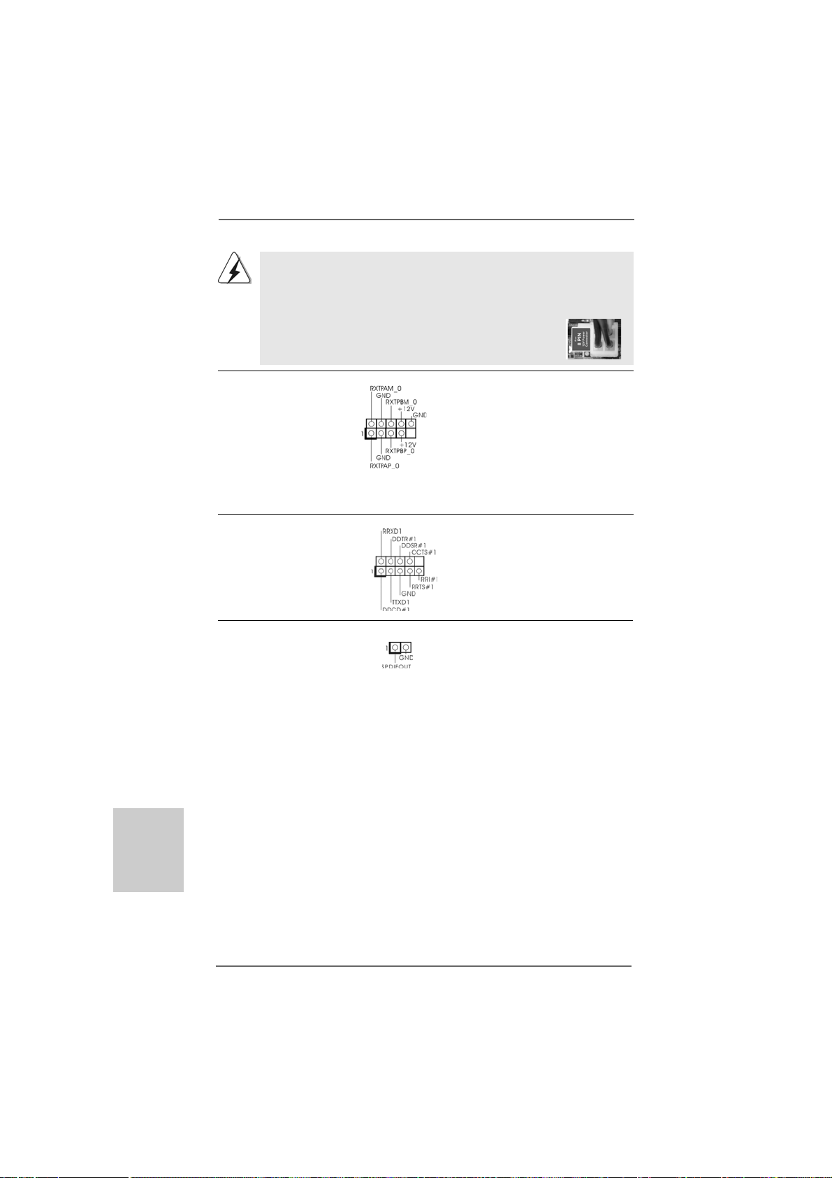
Obwohl diese Hauptplatine 8-Pin ATX 12V Stromanschluss zur Verfügung stellt,
kann sie noch arbeiten, wenn Sie einen traditionellen 4-Pin A TX 12V
Energieversorgung adoptieren. Um die 4-Pin ATX Energieversorgung zu
verwenden, stecken Sie bitte Ihre Energieversorgung zusammen mit dem Pin 1
und Pin 5 ein.
8 5
Installation der 4-Pin A TX 12V Energieversorgung
4 1
IEEE-1394 Header Außer einem vorgegebenem
(9-pin FRONT_1394) IEEE-1394 Port auf dem Ein-/
(siehe S.2 - No. 25) Ausgabe Paneel, gibt es einen
IEEE-1394 Header
(FRONT_1394) auf dieser
Hauptplatine. Dieser IEEE-1394
Header kann einen IEEE-1394
Port unterstützen.
COM-Anschluss-Header Dieser COM-Anschluss-
(9-pin COM1) Header wird verwendet, um
(siehe S.2 - No. 31) ein COM-Anschlussmodul zu
unterstützen.
HDMI_SPDIF-Anschluss Der HDMI_SPDIF-Anschluss
(2-pin HDMI_SPDIF1) stellt einen SPDIF-
(siehe S.2 - No. 33) Audioausgang für eine HDMI-
VGA-Karte zur Verfügung und
ermöglicht den Anschluss von
HDMI-Digitalgeräten wie
Fernsehgeräten, Projektoren,
LCD-Geräten an das System.
Deutsch
DeutschDeutsch
DeutschDeutsch
5858
58
5858
ASRock 880G Pro3 Motherboard
Page 59

2.92.9
SchnellschalterSchnellschalter
2.9
Schnellschalter
2.92.9
SchnellschalterSchnellschalter
Dieses Motherboard besitzt drei Schnellschalter: Netzschalter, Rücksetzschalter
(Reset) und CMOS löschen-Schalter, mit denen Benutzer das System schnell ein-/
ausschalten oder zurücksetzen oder die CMOS-Werte löschen können.
Netzschalter Der Netzschalter ist ein
(PWRBTN) Schnellschalter, mit dem
(siehe S.2 - No. 24) Benutzer das System schnell
ein-/ausschalten können.
Rücksetzschalter (Reset) Der Rücksetzschalter (Reset) ist
(RSTBTN) ein Schnellschalter, mit dem
(siehe S.2 - No. 23) Benutzer das System schnell
RESET
zurücksetzen können.
CMOS löschen-Schalter Der CMOS löschen-Schalter ist
(CLRCBTN) ein Schnellschalter, mit dem
(siehe S.3 - No. 14) Benutzer die CMOS-Werte
Es ist Ihnen bei Einrichtung des Systemkennworts nicht gestattet, die
Schalterfunktion Clear CMOS (CMOS löschen) zu verwenden. Wenn Sie die
CMOS-Werte entfernen möchten, müssen Sie zuerst Ihr Systemkennwort
entfernen, oder Sie können sich stattdessen auch auf die Beschreibung
“Clear CMOS jumper” (CMOS löschen-Jumper) auf Seite 53 beziehen.
2.102.10
Debug-LEDDebug-LED
2.10
Debug-LED
2.102.10
Debug-LEDDebug-LED
Die integrierte Debug-LED liefert Codeinformationen, die eine Fehlerbehebung
erleichtern. Siehe die Abbildungen auf den Seiten 33, 34, 35 und 36 zum Ablesen
der Debug-LED-Codes.
clr
CMOS
schnell löschen können.
DeutschDeutsch
DeutschDeutsch
Deutsch
ASRock 880G Pro3 Motherboard
5959
59
5959
Page 60

2.112.11
TT
2.11
2.112.11
Zur Treiberinstallation Sie bitte die Unterstützungs-CD in Ihr optisches Laufwerk
ein. Anschließend werden die mit Ihrem System kompatiblen Treiber automatisch
erkannt und auf dem Bildschirm angezeigt. Zur Installation der nötigen Treiber
gehen Sie bitte der Reihe nach von oben nach unten vor. Nur so können die von
Ihnen installierten Treiber richtig arbeiten.
reiberinstallationreiberinstallation
T
reiberinstallation
TT
reiberinstallationreiberinstallation
Deutsch
DeutschDeutsch
DeutschDeutsch
®®
®
2.122.12
Windows Windows
2.12
Windows
2.122.12
Windows Windows
XP 64-Bit mit RAID-Funktionalität installieren XP 64-Bit mit RAID-Funktionalität installieren
XP 64-Bit mit RAID-Funktionalität installieren
XP 64-Bit mit RAID-Funktionalität installieren XP 64-Bit mit RAID-Funktionalität installieren
Wenn Sie die Betriebssysteme Windows® 7 / 7 64-bit / VistaTM / VistaTM 64-bit / XP
/ XP 64-bit auf Ihren SATA3-Festplatten mit RAID-Funktionalität installieren
möchten, entnehmen Sie die detaillierten Schritte bitte dem Dokument, das Sie unter
folgendem Pfad auf der Unterstützungs-CD finden:
..\ RAID Installation Guide
2.132.13
Installation von WindowsInstallation von Windows
2.13
Installation von Windows
2.132.13
Installation von WindowsInstallation von Windows
VistaVista
Vista
VistaVista
Wenn Sie Windows® 7 / 7 64-Bit / VistaTM / VistaTM 64-Bit / XP / XP 64-Bit ohne
RAID-Funktionalität auf Ihren SATA3-Festplatten installieren, dann folgen Sie bitte
je nach dem zu installierenden Betriebssystem den folgenden Schritten.
2.13.1 Installation von Windows2.13.1 Installation von Windows
2.13.1 Installation von Windows
2.13.1 Installation von Windows2.13.1 Installation von Windows
Funktionen Funktionen
Funktionen
Funktionen Funktionen
Wenn Sie Windows® XP / XP 64-Bit ohne RAID-Funktionalität auf Ihren SATA3Festplatten installieren, gehen Sie bitte wie folgt vor.
Verwendung von SATA3-Festplatten ohne NCQ und Hot-Plug-Funktionen
SCHRITT 1: Konfigurieren Sie UEFI.
A. Rufen Sie im UEFI-DIENSTPROGRAMM den Bildschirm „Erweitert“ und
„Storage-Konfiguration“ auf.
B. Setzen Sie die Option “SATA Mode” (SATA-Modus) auf [IDE].
SCHRITT 2: Installieren Sie Windows® XP / XP 64-Bit in Ihrem System.
®®
7 / 7 64-Bit / Vista 7 / 7 64-Bit / Vista
7 / 7 64-Bit / Vista
7 / 7 64-Bit / Vista 7 / 7 64-Bit / Vista
TMTM
TM
TMTM
64-Bit / XP / XP 64-Bit ohne RAID-Funktionen 64-Bit / XP / XP 64-Bit ohne RAID-Funktionen
64-Bit / XP / XP 64-Bit ohne RAID-Funktionen
64-Bit / XP / XP 64-Bit ohne RAID-Funktionen 64-Bit / XP / XP 64-Bit ohne RAID-Funktionen
TMTM
TM
TMTM
/ Vista / Vista
/ Vista
/ Vista / Vista
®
7 / 7 64-Bit / Vista 7 / 7 64-Bit / Vista
7 / 7 64-Bit / Vista
7 / 7 64-Bit / Vista 7 / 7 64-Bit / Vista
®
XP / XP 64-Bit ohne RAID- XP / XP 64-Bit ohne RAID-
XP / XP 64-Bit ohne RAID-
XP / XP 64-Bit ohne RAID- XP / XP 64-Bit ohne RAID-
TMTM
TM
TMTM
64-Bit / XP / 64-Bit / XP /
64-Bit / XP /
64-Bit / XP / 64-Bit / XP /
TMTM
TM
TMTM
/ /
/
/ /
6060
60
6060
ASRock 880G Pro3 Motherboard
Page 61

2.13.2 Installation von Windows2.13.2 Installation von Windows
2.13.2 Installation von Windows
2.13.2 Installation von Windows2.13.2 Installation von Windows
TMTM
TM
Vista Vista
Vista
Vista Vista
Wenn Sie Windows® 7 / 7 64-Bit / VistaTM / VistaTM 64-Bit ohne RAID-Funktionalität
auf Ihren SATA3-Festplatten installieren, gehen Sie bitte wie folgt vor.
Verwendung von SATA3-Festplatten ohne NCQ und Hot-Plug-Funktionen
SCHRITT 1: Konfigurieren Sie UEFI.
A. Rufen Sie im UEFI-DIENSTPROGRAMM den Bildschirm „Erweitert“ und
„Storage-Konfiguration“ auf.
B. Setzen Sie die Option “SATA Mode” (SATA-Modus) auf [IDE].
SCHRITT 2: Installieren Sie Windows® 7 / 7 64-Bit / VistaTM / VistaTM 64-Bit in
Verwendung von SATA3-Festplatten mit NCQ und Hot-Plug-Funktionen
SCHRITT 1: Konfigurieren Sie UEFI.
A. Rufen Sie im UEFI-DIENSTPROGRAMM den Bildschirm „Erweitert“ und
„Storage-Konfiguration“ auf.
B. Setzen Sie die Option “SATA Mode” (SATA-Modus) auf [AHCI].
SCHRITT 2: Installieren Sie Windows® 7 / 7 64-Bit / VistaTM / VistaTM 64-Bit in
TMTM
64-Bit ohne RAID-Funktionen 64-Bit ohne RAID-Funktionen
64-Bit ohne RAID-Funktionen
64-Bit ohne RAID-Funktionen 64-Bit ohne RAID-Funktionen
Ihrem System.
Ihrem System.
®
7 / 7 64-Bit / Vista 7 / 7 64-Bit / Vista
7 / 7 64-Bit / Vista
7 / 7 64-Bit / Vista 7 / 7 64-Bit / Vista
TMTM
TM
TMTM
/ /
/
/ /
ASRock 880G Pro3 Motherboard
6161
61
6161
DeutschDeutsch
DeutschDeutsch
Deutsch
Page 62

3. BIOS-Information3. BIOS-Information
3. BIOS-Information
3. BIOS-Information3. BIOS-Information
Das Flash Memory dieses Motherboards speichert das Setup-Utility. Drücken Sie
<F2> während des POST (Power-On-Self-Test) um ins Setup zu gela ngen, ansonsten
werden die Testroutinen weiter abgearbeitet. Wenn Sie ins Setup gelangen wollen,
nachdem der POST durchgeführt wurde, müssen Sie das System über die
Tastenkombination <Ctrl> + <Alt> + <Delete> oder den Reset-Knopf auf der
Gehäusevorderseite, neu starten. Natürlich können Sie einen Neustart auch
durchführen, indem Sie das System kurz ab- und danach wieder anschalten.
Das Setup-Programm ist für eine bequeme Bedienung entwickelt worden. Es ist
ein menügesteuertes Programm, in dem Sie durch unterschiedliche Untermenüs
scrollen und die vorab festgelegten Optionen auswählen können. Für detaillierte
Informationen zum BIOS-Setup, siehe bitte das Benutzerhandbuch (PDF Datei) auf
der Support CD.
4. Software Support CD information4. Software Support CD information
4. Software Support CD information
4. Software Support CD information4. Software Support CD information
Dieses Motherboard unterstützt eine Reiche von Microsoft® Windows
Betriebssystemen: 7 / 7 64-Bit / VistaTM / Vista
Motherboard beigefügte Support-CD enthält hilfreiche Software, Treiber und
Hilfsprogramme, mit denen Sie die Funktionen Ihres Motherboards verbessern
können Legen Sie die Support-CD zunächst in Ihr CD-ROM-Laufwerk ein. Der
Willkommensbildschirm mit den Installationsmenüs der CD wird automatisch
aufgerufen, wenn Sie die “Autorun”-Funktion Ihres Systems aktiviert haben.
Erscheint der Wilkommensbildschirm nicht, so “doppelklicken” Sie bitte auf das File
ASSETUP.EXE im BIN-Verzeichnis der Support-CD, um die Menüs aufzurufen. Das
Setup-Programm soll es Ihnen so leicht wie möglich machen. Es ist menügesteuert,
d.h. Sie können in den verschiedenen Untermenüs Ihre Auswa hl treffen und die
Programme werden dann automatisch installiert.
TM
64-Bit / XP / XP 64-Bit. Die Ihrem
®
Deutsch
DeutschDeutsch
DeutschDeutsch
6262
62
6262
ASRock 880G Pro3 Motherboard
Page 63
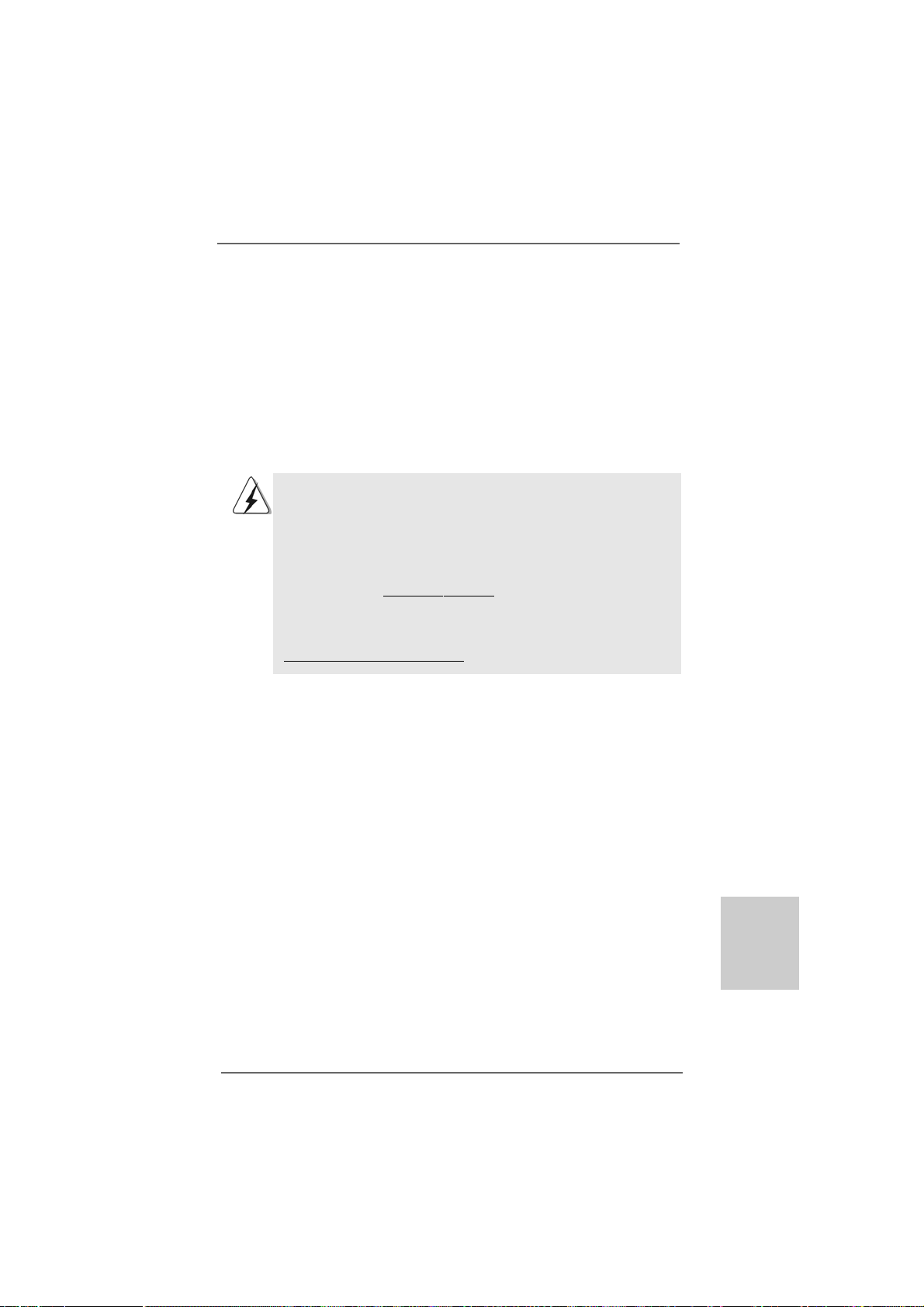
1. Introduction1. Introduction
1. Introduction
1. Introduction1. Introduction
Merci pour votre achat d’une carte mère ASRock 880G Pro3 une carte mère très
fiable produite selon les critères de qualité rigoureux de ASRock. Elle offre des
performances excellentes et une conception robuste conformément à l’engagement
d’ASRock sur la qualité et la fiabilité au long terme.
Ce Guide d’installation rapide présente la carte mère et constitue un guide
d’installation pas à pas. Des informations plus détaillées concernant la carte mère
pourront être trouvées dans le manuel l’utilisateur qui se trouve sur le CD
d’assistance.
Les spécifications de la carte mère et le BIOS ayant pu être mis à
jour, le contenu de ce manuel est sujet à des changements sans
notification. Au cas où n’importe qu’elle modification intervenait sur ce
manuel, la version mise à jour serait disponible sur le site web
ASRock sans nouvel avis. Vous trouverez les listes de prise en
charge des cartes VGA et CPU également sur le site Web ASRock.
Site web ASRock, http://www.asrock.com
Si vous avez besoin de support technique en relation avec cette carte
mère, veuillez consulter notre site Web pour de plus amples
informations particulières au modèle que vous utilisez.
www.asrock.com/support/index.asp
1.11.1
Contenu du paquetContenu du paquet
1.1
Contenu du paquet
1.11.1
Contenu du paquetContenu du paquet
Carte mère ASRock 880G Pro3
(Facteur de forme ATX: 12.0 pouces x 9.6 pouces, 30.5 cm x 24.4 cm)
Guide d’installation rapide ASRock 880G Pro3
CD de soutien ASRock 880G Pro3
Deux câble de données Serial ATA (SATA) (Optionnelle)
Un écran I/O
ASRock 880G Pro3 Motherboard
6363
63
6363
çaisçais
çaisçais
çais
FranFran
FranFran
Fran
Page 64

Français
FrançaisFrançais
FrançaisFrançais
1.21.2
SpécificationsSpécifications
1.2
Spécifications
1.21.2
SpécificationsSpécifications
Format - Facteur de forme ATX:
12.0 pouces x 9.6 pouces, 30.5 cm x 24.4 cm
- Accessoires de Carte mère
CPU - Prise en charge des processeurs sur socket AM3+
- Prise en charge des processeurs sur socket AM3: Processeur
PhenomTM II X6 / X4 / X3 / X2 (sauf 920 / 940) / Athlon II X4 / X3
/ X2 / Sempron d’AMD
- Prêt pour processeurs Huit-Core
- Supporte UCC (Unlock CPU Core) (voir ATTENTION 1)
- Conception 4 + 1 Power Phase
- Supporte les processeurs jusqu’à 140W
- Supporte la technologie Cool ‘n’ QuietTM d’AMD
- FSB 2600 MHz (5.2 GT/s)
- Prend en charge la technologie Untied Overclocking
(voir ATTENTION 2)
- Prise en charge de la technologie Hyper Transport 3.0
(HT 3.0)
Chipsets - Northbridge: AMD 880G
- Southbridge: AMD SB850
Mémoire - Compatible avec la Technologie de Mémoire à Canal Double
(voir ATTENTION 3)
- 4 x slots DIMM DDR3
- Supporter DDR3 1866(OC)/1800(OC)/1600(OC)/1333/1066/
800 non-ECC, sans amortissement mémoire
(voir ATTENTION 4)
- Capacité maxi de mémoire système: 32GB
(voir ATTENTION 5)
Slot d’extension - 2 x slots PCI Express 2.0 x16
(PCIE2 @ mode x16; PCIE3 @ mode x4)
- 1 x slot PCI Express 2.0 x1
- 3 x slots PCI
- Prend en charge ATITM Quad CrossFireXTM, CrossFireXTM et
Hybrid CrossFireX
VGA sur carte - Graphiques intégrés à l’AMD Radeon HD 4250
- DX10.1 classe iGPU, Shader Model 4.1
- mémoire partagée max 512MB (voir ATTENTION 6)
- Trois options de sortie VGA : D-Sub, DVI-D et HDMI
- Prend en charge le HDMI avec une résolution maximale
jusqu’à 1920x1200 (1080p)
TM
6464
64
6464
ASRock 880G Pro3 Motherboard
Page 65

- Prend en charge le D VI Dual-link ave c une résolution maximale
jusqu’à 2560x1600 @ 75Hz
- Prend en charge le D-Sub avec une résolution maximale
jusqu’à 2048x1536 @ 85Hz
- Prise en charge de la fonction HDCP avec ports DVI et HDMI
- Supporter 1080p Blu-ray(BD)/ lecteur de HD-DVD avec ports
D VI et HDMI
Audio - 7,1 CH HD Audio avec protection de contenu
(Realtek ALC892 Audio Codec)
- Prise en charge de l’audio Premium Blu-ray
LAN - PCIE x1 Giga bit LAN 10/100/1000 Mb/s
- Atheros® AR8151
- Support du Wake-On-LAN
Panneau arrière I/O Panel
- 1 x port clavier PS/2
- 1 x port VGA/D-Sub
- 1 x port VGA/DVI-D
- 1 x port HDMI
- 1 x Port de sortie optique SPDIF
- 4 x ports USB 2.0 par défaut
- 1 x Connecteur eSATA3
- 2 x ports USB 3.0 par défaut
- 1 x port LAN RJ-45 avec LED (ACT/LED CLIGNOTANTE et
LED VITESSE)
- 1 x port IEEE 1394
- 1 x interrupteur d’effacement du CMOS
- Prise HD Audio: Haut-parleur arrière / Central /Basses / Entrée
Ligne / Haut-parleur frontal / Microphone
(voir ATTENTION 7)
SATA3 - 5 x connecteurs 6,0 Gb/s SATA3, prise en charge des
fonctions RAID (RAID 0, RAID 1, RAID 0+1 et RAID 5), NCQ,
AHCI et « Connexion à chaud »
USB 3.0 - 2 x ports USB3.0 par Etron EJ168A, prennent en charge
USB 1.0/2.0/3.0 jusqu’à 5 Gb/s
Connecteurs - 5 x connecteurs SATA3, prennent en charge un taux de
transfert de données pouvant aller jusqu’à 6.0Go/s
- 1 x En-tête du module infrarouge
- 1 x En-tête de port COM
- 1 x Connecteur IEEE 1394
- 1 x Connecteur HDMI_SPDIF
- 1 x LED di accensione
- Connecteur pour ventilateur de CPU/Châssis/Ventilateur
ASRock 880G Pro3 Motherboard
6565
65
6565
çaisçais
çaisçais
çais
FranFran
FranFran
Fran
Page 66

Français
FrançaisFrançais
FrançaisFrançais
6666
66
6666
- br. 24 connecteur d’alimentation ATX
- br. 8 connecteur d’alimentation 12V ATX
- Connecteur audio panneau avant
- 3 x En-tête USB 2.0 (prendre en charge 6 ports USB 2.0
supplémentaires)
- 1 x Dr. Debug (LED de débogage à 7 segments)
Interrupteur - 1 x interrupteur d’effacement du CMOS avec LED
rapide - 1 x interrupteur d’alimentation avec LED
- 1 x interrupteur de réinitialisation avec LED
BIOS - 32Mb AMI UEFI Legal BIOS avec support GUI
- Support du “Plug and Play”
- Compatible pour événements de réveil ACPI 1.1
- Gestion jumperless
- Support SMBIOS 2.3.1
- CPU, VCCM, NB, SB Tension Multi-ajustement
CD d’assistance - Pilotes, utilitaires, logiciel anti-virus (Version d’essai),
Utilitaire AMD OverDriveTM, AMD Live! Explorer, AMD Fusion,
Suite logicielle ASRock (CyberLink D V D Suite et Creative Sound
Blaster X-Fi MB) (Version OEM et d’essai)
Caractéristique - Utilitaire ASRock Extreme Tuning (AXTU)
Caractéristique (voir ATTENTION 8)
unique - l'Instant Boot
- ASRock Instant Flash (voir ATTENTION 9)
- ASRock AIWI (voir ATTENTION 10)
- Chargeur ASRock APP (voir ATTENTION 11)
- SmartView (voir ATTENTION 12)
- ASRock XFast USB (voir ATTENTION 13)
- L’accélérateur hybride:
- Contrôle direct de la fréquence CPU
(voir ATTENTION 14)
- ASRock U-COP (voir ATTENTION 15)
- Garde d’échec au démarrage (B.F.G.)
- Turbo 40 / Turbo 50 GPU Overclocking
- Turbo UCC
Surveillance - Détection de la température de l’UC
système - Mesure de température de la carte mère
- Tachéomètre ventilateur CPU/Châssis/Ventilateur
- Ventilateur silencieux d’unité centrale
- Commande de ventilateur CPU/boîtier à plusieurs vitesses
- Monitoring de la tension: +12V, +5V, +3.3V, Vcore
OS - Microsoft® Windows® 7 / 7 64-bit / Vista
XP / XP 64-bit
ASRock 880G Pro3 Motherboard
TM
/ VistaTM 64-bit /
Page 67

Certifications - FCC, CE, WHQL
- Prêt pour ErP/EuP (alimentation Prêt pour ErP/EuP requise)
(voir ATTENTION 16)
* Pour de plus amples informations sur les produits, s’il vous plaît visitez notre site web:
http://www.asrock.com
A TTENTION
Il est important que vous réalisiez qu’il y a un certain risque à effectuer l’overclocking, y
compris ajuster les réglages du BIOS, appliquer la technologie Untied Overclocking, ou
utiliser des outils de tiers pour l’overclocking. L’overclocking peut affecter la stabilité de
votre système, ou même causer des dommages aux composants et dispositifs de votre
système. Si vous le faites, c’est à vos frais et vos propres risques. Nous ne sommes
pas responsables des dommages possibles causés par l’overclocking.
ATTENTION!
1. La fonction ASRock UCC (Unlock CPU Core : Déverrouillage du coeur
du processeur) permet de simplifier l’activation des processeurs AMD. Il
vous suffit de sélectionner dans le UEFI l’option « Unlock CPU Core »
(Déverrouillage du coeur du processeur), et vous pouvez déverrouiller le
coeur du processeur pour profiter instantanément de performances
renforcées. Lorsque la fonction UCC est activée, le processeur à
double ou à triple coeur sera renforcée de façon à fonctionner comme
processeur à quatre coeurs, et pour certains processeurs, notamment
les processeurs quad-core, la taille du cache L3 sera aussi augmentée
pour passer à 6 Mo, ce qui signifie que vous pourrez améliorer les
performances du processeur à plus faible coût. Veuillez noter que la
fonction UCC est prise en charge uniquement avec les processeurs
AM3/AM3+, et en outre, tous les processeurs AM3/AM3+ ne prennent
pas cette fonction en charge car certains coeurs cachés de processeurs
risquent de dysfonctionner.
2. Cette carte mère prend en charge la technologie Untied Overclocking.
Veuillez lire “La technologie de surcadençage à la volée” à la page 38
pour plus d’informations.
3. Cette carte mère supporte la Technologie de Mémoire à Canal Double.
Avant d’intégrer la Technologie de Mémoire à Canal Double, assurezvous de bien lire le guide d’installation des modules mémoire en page 72
pour réaliser une installation correcte.
4. La prise en charge de fréquences de mémoire de 1866/1800/1600MHz
dépend du CPU AM3/AM3+ que vous choisissez. Si vous choisissez
des barrettes de mémoire DDR3 1866/1800/1600 sur cette carte mère,
veuillez vous référer à la liste des mémoires prises en charge sur notre
site Web pour connaître barrettes de mémoire compatibles.
Site Web ASRock
5. Du fait des limites du système d’exploitation, la taille mémoire réelle
réservée au système pourra être inférieure à 4 Go sous Windows® 7 /
VistaTM / XP. Avec Windows® OS avec CPU 64 bits, il n’y a pas ce genre
de limitation.
http://www.asrock.com
çaisçais
çaisçais
çais
FranFran
FranFran
Fran
ASRock 880G Pro3 Motherboard
6767
67
6767
Page 68

Français
FrançaisFrançais
FrançaisFrançais
6. La dimension maximum du memoire partage est definie par le vendeur de
jeu de puces et est sujet de changer. Veuillez verifier la AMD website pour
les informations recentes SVP.
7. Pour l’entrée microphone, cette carte mère supporte les deux modes
stéréo et mono. Pour la sortie audio, cette carte mère supporte les
modes 2-canaux, 4-canaux, 6-canaux et 8-canaux. Veuillez vous référer
au tableau en page 3 pour effectuer la bonne connexion.
8. ASRock Extreme Tuning Utility (AXTU) est un utilitaire tout-en-un qui
permet de régler précisément différentes fonctions du système, via
une interface facile à utiliser, incluant Moniteur de périphériques,
Contrôle du ventilateur, Overclocking, OC DNA et IES. Dans Moniteur
de périphériques, il affi che les valeurs principales de votre système.
Dans Contrôle du ventilateur, il affi che la vitesse du ventilateur et la
température, que vous pouvez ajuster. Dans Overclocking, vous
pouvez overclocker la fréquence du CPU pour améliorer les
performances du système. Dans OC DNA, vous pouvez enregistrer
vos réglages OC dans un profi l et les partager avec vos amis. Vos
amis pourront alors installer le profi l OC sur leur système pour utiliser
les mêmes réglages OC. Dans IES (Intelligent Energy Saver – Fonction
intelligente d’économie d’énergie), le contrôleur de la tension peut réduire
le nombre de phases de sortie pour améliorer le fonctionnement lorsque
les cores du CPU ne sont pas utilisées, sans diminuer les performances
de l’ordinateur. Veuillez visiter notre site Web pour plus d’informations
sur l’utilisation des fonctions de l’utilitaire ASRock Extreme Tuning
Utility (AXTU). Site Web de ASRock :
9. O ASRock Instant Flash é um utilitário de flash do BIOS incorporado na
memória Flash ROM. Esta prática ferramenta de actualização do BIOS
permite-lhe actualizar o BIOS do sistema sem necessitar de entrar nos
sistemas operativos, como o MS-DOS ou o Windows®. Com este
utilitário, poderá premir a tecla <F6> durante o teste de arranque POST
ou premir a tecla <F2> para exibir o menu de configuração do BIOS
para aceder ao ASRock Instant Flash. Execute esta ferramenta para
guardar o novo ficheiro de BIOS numa unidade flash USB, numa
disquete ou num disco rígido, em seguida, poderá actualizar o BIOS
com apenas alguns cliques sem ter de utilizar outra disquete ou outro
complicado utilitário de flash. Note que a unidade flash USB ou a
unidade de disco rígido devem utilizar o sistema de ficheiros FAT32/16/
12.
10. Le plaisir des jeux contrôlés par mouvement intuitif n’est plus réservé à
la Wii. L’utilitaire ASRock AIWI présente une nouvelle forme de contrôle
des jeux sur PC. ASRock AIWI est le premier utilitaire du monde à
transformer votre iPhone/iPod en manette de jeu qui vous permet de
contrôler vos jeux sur PC. Il vous suffit simplement d’installer l’utilitaire
ASRock AIWI à partir du site web officiel ASRock ou du CD logiciels
ASRock sur votre carte-mère, et de télécharger également l’utilitaire
gratuit AIWI Lite à partir de App store sur votre iPhone/iPod touch. Il
http://www.asrock.com
6868
68
6868
ASRock 880G Pro3 Motherboard
Page 69

vous faut aussi connecter votre PC et vos appareils Apple via
Bluetooth ou WiFi, et vous pouvez commencer à profiter du plaisir des
jeux contrôlés par mouvement. N’oubliez pas non plus de visiter
régulièrement le site web officiel d’ASRock, nous fournissons en
permanence les derniers jeux compatibles !
Site web ASRock : http://www.asrock.com/Feature/Aiwi/index.asp
11. Si vous désirez un moyen plus rapide et moins contraignant de
recharger vos appareils Apple tels que iPhone/iPod/iPad Touch, ASRock
a préparé pour vous la solution idéale - le chargeur ASRock APP. Il
suffit d’installer le pilote du chargeur APP, et vous pourrez recharger
rapidement votre iPhone à partir de votre ordinateur, jusqu’à 40% plus
vite qu’avant. Le chargeur ASRock APP vous permet de charger
rapidement et simultanément plusieurs appareils Apple, et le chargement
continu est même pris en charge lorsque le PC passe en mode Veille
(S1), Suspension à la RAM (S3), hibernation (S4) ou hors tension (S5).
Lorsque le pilote du chargeur APP est installé, vous découvrez un mode
de mise en charge tout à fait inédit.
Site web ASRock : http://www.asrock.com/Feature/AppCharger/index.
asp
12. SmartView, nouvelle fonction pour les navigateurs Internet, est une page
de démarrage intelligente pour IE qui combine vos sites web les plus
visités, votre historique, vos amis Facebook et vos fils d’actualité en
temps réel, le tout sous forme d’affichage évolué, pour une expérience
Internet plus personnelle. Les cartes mères ASRock sont équipées de
l’utilitaire SmartView qui vous aide à garder le contact avec vos proches à
tout moment. Pour utiliser la fonction SmartView, veuillez vous assurer
que votre système d’exploitation est Windows
VistaTM 64 bits, et que la version de votre navigateur est IE8.
Site web ASRock : http://www.asrock.com/Feature/SmartView/index.asp
13. ASRock XFast USB permet d’améliorer les performances de votre
périphérique de stockage USB. Les performances réelles dépendent des
propriétés du périphérique.
14. Même si cette carte mère offre un contrôle sans souci, il n’est pas
recommandé d’y appliquer un over clocking. Les fréquences autres que
les fréquences de bus d’UC recommandées risquent de déstabiliser le
système ou d’endommager l’UC.
15. Lorsqu’une surchauffe du CPU est détectée, le système s’arrête
automatiquement. Avant de redémarrer le système, veuillez vérifier que
le ventilateur d’UC sur la carte mère fonctionne correctement et
débranchez le cordon d’alimentation, puis rebranchez-le. Pour améliorer
la dissipation de la chaleur, n’oubliez pas de mettre de la pâte thermique
entre le CPU le dissipateur lors de l’installation du PC.
16. EuP, qui signifie Energy Using Product (Produit Utilisant de l’Energie), est
une disposition établie par l’Union Européenne pour définir la consommation
de courant pour le système entier. Conformément à la norme EuP, le
courant CA total du système entier doit être inférieur à 1 W en mode
d’arrêt. Pour être conforme à la norme EuP, une carte mère EuP et une
®
7 / 7 64 bits / VistaTM ou
çaisçais
çaisçais
çais
FranFran
FranFran
Fran
ASRock 880G Pro3 Motherboard
6969
69
6969
Page 70

Français
FrançaisFrançais
FrançaisFrançais
alimentation EuP sont requises. Selon les suggestions d’Intel’, l’alimentation
électrique EuP doit correspondre à la norme, qui est que l’efficacité électrique
de 5v en mode de veille doit être supérieure à 50% pour 100 mA de
consommation de courant. Pour choisir une alimentation électrique conforme
à la norme EuP, nous vous recommandons de consulter votre fournisseur
de courant pour plus de détails.
2. Installation2. Installation
2. Installation
2. Installation2. Installation
Il s’agit d’une carte mère à facteur de forme ATX (12,0 po x 9,6 po, 30,5 cm x
24,4 cm). Avant d’installer la carte mère, étudiez la configuration de votre châssis
pour vous assurer que la carte mère s’y insère.
Précautions à observer avant l’installationPrécautions à observer avant l’installation
Précautions à observer avant l’installation
Précautions à observer avant l’installationPrécautions à observer avant l’installation
Veuillez tenir compte des précautions suivantes avant l’installation des
composants ou tout réglage de la carte mère.
Avant d’installer ou de retirer un composant, assurez-vous que l’alimentation
est mise hors tension ou que la fiche électrique est débranchée de
l’alimentation électrique. Dans le cas contraire, la carte mère, des périphériques
et/ou des composants risquent d’être gravement endommagés.
1. Débranchez le câble d’alimentation de la prise secteur avant
de toucher à tout composant. En ne le faisant pas, vous
pouvez sérieusement endommager la carte mère, les
périphériques et/ou les composants.
2. Pour éviter d’endommager les composants de la carte mère
du fait de l’électricité statique, ne posez JAMAIS votre carte
mère directement sur de la moquette ou sur un tapis.
N’oubliez pas d’utiliser un bracelet antistatique ou de toucher
un objet relié à la masse avant de manipuler les composants.
3. Tenez les composants par les bords et ne touchez pas les
circuits intégrés.
4. A chaque désinstallation de composant, placez-le sur un
support antistatique ou dans son sachet d’origine.
5. Lorsque vous placez les vis dans les orifices pour vis pour
fixer la carte mère sur le châssis, ne serrez pas trop les vis
! Vous risquez sinon d’endommager la carte mère.
7070
70
7070
ASRock 880G Pro3 Motherboard
Page 71

2.1 Installation du CPU2.1 Installation du CPU
2.1 Installation du CPU
2.1 Installation du CPU2.1 Installation du CPU
Etape 1. Déverrouillez le support en relevant le levier selon un angle de 90o.
Etape 2. Placer l’UC directement au-dessus de la prise pour que le coin de l’UC avec
son triangle jaune coïncide avec le petit triangle dans le coin de la prise.
Etap e 3. Insérez avec précaution le CPU dans le support jusqu’à ce qu’il soit bien en
place.
Le CPU ne peut être inséré que dans un seul sens. NE JAMAIS
forcer le CPU dans le support pour éviter de tordre ses broches.
Etape 4. Quand le CPU est en place, appuyez fermement dessus tout en abaissant
le levier du support pour bloquer le CPU. Le verrouillage du levier dans son
encoche latérale est annoncé par un clic.
Levier 90°
Haut
ETAPE 1 :
Levez le levier de prise
2.22.2
Installation du ventilateur et du dissipateurInstallation du ventilateur et du dissipateur
2.2
Installation du ventilateur et du dissipateur
2.22.2
Installation du ventilateur et du dissipateurInstallation du ventilateur et du dissipateur
Triangle doré du
processeur
Petit triangle du
côté de la prise
ETAPE 2 / ET APE 3 :
Mettez le triangle doré du
processeur
sur le petit triangle du côté de la
prise
ETAPE 4 :
Appuyez et verrouillez
le levier de la prise
Une fois que vous avez installé le CPU dans cette carte mère, il faut
installer un dissipateur plus grand et un ventilateur de refroidissement pour
dissiper la chaleur. Vous devez également asperger de la pâte thermique
entre le CPU et le dissipateur pour améliorer la dissipation de chaleur.
Assurez-vous que le CPU et le dissipateur sont fermement fixés et en bon
contact l’un avec l’autre. Ensuite, connectez le ventilateur du CPU à la prise
du VENTILA TEUR DU CPU (CPU_FAN1, reportez-vous en page 2, No. 6 ou
CPU_FAN2, reportez-vous en page 2, No. 5). Pour une bonne installation,
veuillez vous référer aux manuels d’instruction sur le ventilateur du CPU et
le dissipateur.
çaisçais
çaisçais
çais
FranFran
FranFran
Fran
ASRock 880G Pro3 Motherboard
7171
71
7171
Page 72

2.3 Installation des modules m émoire [DIMM]2.3 Installation des modules m émoire [DIMM]
2.3 Installation des modules m émoire [DIMM]
2.3 Installation des modules m émoire [DIMM]2.3 Installation des modules m émoire [DIMM]
La carte mère 880G Pro3 dispose de quatre emplacements DIMM DDR3 (Double
Data Rate 3) de 240-broches, et supporte la Technologie de Mémoire à Canal
Double. Pour effectuer une configuration à canal double, vous devez toujours
installer des paires de DIMM DDR3 identiques (de la même marque, de la même
vitesse, de la même taille et du même type de puce) dans les slots de même
couleur. En d’autres termes, vous devez installer une paire de DIMM DDR3
identiques dans le Canal Double A (DDR3_A1 et DDR3_B1; slots bleu; voir p.2 No.
8) ou une paire de DIMM DDR3 identiques dans le Ca n al Double B (DDR3_A2 et
DDR3_B2; slots blanc; voir p.2 No. 9), de façon à ce que la Technologie de
Mémoire à Canal Double puisse être activée. Cette carte vous permet également
d’installer quatre modules DIMM DDR3 pour la configuration à ca n al double. Cette
carte mère vous permet également d’installer quatre modules DIMM DDR3 pour une
configuration double canal; veuillez installer les mêmes modules DIMM DDR3 dans
les quatre emplacements. Vous pouvez vous reporter au Tableau de configuration
mémoire double canal ci-dessous.
Configurations de Mémoire à Canal Double
DDR3_A1 DDR3_A2 DDR3_B1 DDR3_B2
(Slot Bleu) (Slot Blanc) (Slot Bleu) (Slot Blanc)
(1) Occupé - Occupé (2) - Occupé - Occupé
(3) Occupé Occupé Occupé Occupé
Français
FrançaisFrançais
FrançaisFrançais
7272
72
7272
* Pour la configuration (3), veuillez installer des DIMM DDR3 identiques dans les
quatre emplacements.
1. Si vous voulez installer deux modules de mémoire, pour une
compatibilité et une fiabilité optimales, il est recommandé de les
installer dans des emplacements de la même couleur. En d’autres
termes, installez-les soit dans les emplacements bleu (DDR3_A1 et
DDR3_B1), soit dans les emplacements blanc (DDR3_A2 et
DDR3_B2).
2. Si un seul module mémoire ou trois modules mémoire sont installés
dans les slots DIMM DDR3 sur cette carte mère, il sera impossible
d’activer la Technologie de Mémoire à Canal Double.
3. Si une paire de modules mémoire N’est PAS installée dans le
même “Canal Double”, par exemple, installer une paire de modules
mémoire dans le DDR3_A1 et le DDR3_A2, il sera impossible
d’activer la Technologie de Mémoire à Canal Double.
4. Il n’est pas permis d’installer de la DDR ou DDR2 sur le slot
DDR3; la carte mère et les DIMM pourraient être endommagés.
ASRock 880G Pro3 Motherboard
Page 73

5. Si vous adoptez des modules de mémoire DDR3 1866/1800/1600
sur cette carte mère, il est recommandé de les installer dans les
fentes DDR3_A2 et DDR3_B2.
Installation d’un module DIMMInstallation d’un module DIMM
Installation d’un module DIMM
Installation d’un module DIMMInstallation d’un module DIMM
Ayez bien le soin de débrancher l’alimentation avant d’ajouter ou de
retirer des modules DIMM ou les composants du système.
Etape 1. Déverrouillez un connecteur DIMM en poussant les taquets de maintien
vers l’extérieur.
Etap e 2 . Alignez le module DIMM sur son emplacement en faisant corre spondre le s
encoches du module DIMM aux trous du connecteur.
Le module DIMM s’insère uniquement dans un seul sens. Si vous
forcezle module DIMM dans son emplacement avec une mauvaise
orientation cela provoquera des dommages irrémédiables à la carte
mère et au module DIMM.
Etape 3. Insérez fermement le module DIMM dans son empla ce ment jus qu’à ce que
les clips de maintien situés aux deux extrémités se ferment complètement
et que le module DIMM soit inséré correctement.
ASRock 880G Pro3 Motherboard
7373
73
7373
çaisçais
çaisçais
çais
FranFran
FranFran
Fran
Page 74

Français
FrançaisFrançais
FrançaisFrançais
2.42.4
Slot d’extension (Slots PCI et Slots PCI Express)Slot d’extension (Slots PCI et Slots PCI Express)
2.4
Slot d’extension (Slots PCI et Slots PCI Express)
2.42.4
Slot d’extension (Slots PCI et Slots PCI Express)Slot d’extension (Slots PCI et Slots PCI Express)
Il y a 3 ports PCI et 3 ports PCI Express sur la carte mère 880G Pro3.
Slots PCI: Les slots PCI sont utilisés pour installer des cartes d’extension dotées
d’une interface PCI 32 bits.
Slots PCIE:
Le PCIE1 (slot PCIE x1; blanc) sert aux cartes PCI Express avec les
cartes de largeur x1 voie, comme la carte Gigabit LAN, la carte SATA2.
Le PCIE2 (slot PCIE x16; bleu) sert aux cartes graphique s PCI Express de
largeur x16 voies, ou sert à installer des cartes graphiques PCI Express
pour prendre en charge la fonction CrossFireXTM.
Le PCIE3 (slot PCIE x16; bleu) sert aux cartes graphique s PCI Express de
largeur x4 voie, ou sert à installer des cartes graphiques PCI Express
pour prendre en charge la fonction CrossFireXTM.
1. En mode de carte VGA unique, il est recommandé d’installer une
carte graphique PCI Express x16 dans la fente PCIE2.
2. En mode CrossFireXTM, installez une carte graphique PCI Express
x16 dans les fentes PCIE2 et PCIE3.
3. Reliez un ventilateur de châssis au connecteur pour ventilateur
de châssis de la carte mère (CHA_FAN1, CHA_FAN2 ou
CHA_FAN3) lorsque vous utilisez plusieurs cartes graphiques afin
d’obtenir un meilleur environnement thermique.
Installation d’une carte d’extensionInstallation d’une carte d’extension
Installation d’une carte d’extension
Installation d’une carte d’extensionInstallation d’une carte d’extension
Etape 1. Avant d’installer les cartes d’extension, veuillez vous assurer de bien
avoir coupé l’alimentation ou d’avoir débranché le cordon d’alimentation.
Veuillez lire la documentation des cartes d’extension et effectuer les
réglages matériels nécessaires pour les cartes avant de débuter
l’installation.
Etape 2. Retirez l’équerre correspondant au connecteur que vous voulez utiliser.
Gardez la vis pour un usage ultérieur.
Eta pe 3. Alignez la carte sur le connecteur et appuyez fermement jusqu’à l’insertion
complète de la carte dans son emplacement.
Etape 4. Fixez la carte sur le châssis à l’aide d’une vis.
7474
74
7474
ASRock 880G Pro3 Motherboard
Page 75

TMTM
TM
2.52.5
Guide d’utilisation de AGuide d’utilisation de A
2.5
Guide d’utilisation de A
2.52.5
Guide d’utilisation de AGuide d’utilisation de A
Cette carte mère prend en charge la fonctionnalité ATITM Hybrid CrossFireXTM. ATI
Hybrid CrossFireXTM apporte des capacités de performances multi-GPU en
permettant à un processeur graphique intégré AMD 880G et à un processeur
graphique séparé de fonctionner simultanément, avec une sortie combinée vers
un unique écran, pour des débits d’images rapides comme l’éclair. Actuellement, la
technologie A TITM Hybrid CrossFireXTM n’est prise en charge que par l’OS
Windows® VistaTM / 7, et n’est pas disponible avec l’OS Windows® XP. A l’avenir,
ATITM Hybrid CrossFireXTM pourra être prise en charge avec l’OS Windows® XP.
Veuillez visiter notre site Web pour des informations mises à jour. Pour la
procédure de fonctionnement détaillée et la liste des cartes graphiques PCI
Express compatibles, veuillez vous référer à la page 20.
2.62.6
Mode d’emploi pour CrossFireXMode d’emploi pour CrossFireX
2.6
Mode d’emploi pour CrossFireX
2.62.6
Mode d’emploi pour CrossFireXMode d’emploi pour CrossFireX
TMTM
TM
CrossFireXCrossFireX
CrossFireX
CrossFireXCrossFireX
Cette carte mère prend en charge CrossFireXTM et Quad CrossFireXTM. La
technologie CrossFireXTM offre le moyen le plus avantageux de combiner divers
dispositifs de traitement graphique performants (GPU) dans un seul PC. Combinez
une gamme de modes d’exploitation différents avec des logiciels intelligents et des
mécanismes d’interconnexion innovants. CrossFireXTM permet d’obtenir le niveau
de performance le plus haut possible et une haute qualité d’image pour les
applications 3D. En général, CrossFireXTM est pris en charge par Windows® XP
avec le Pack de service 2 / VistaTM / 7. Quad CrossFireXTM est pris en charge par
Windows® VistaTM / 7 uniquement. Veuillez consulter le site d’AMD pour les mises
à jour de driver ATITM CrossFireXTM. Veuillez suivre les instructions d’installation de
la page 22 pour plus de détails.
TMTM
TMTM
TITI
Hybrid CrossF Hybrid CrossF
TI
Hybrid CrossF
TITI
Hybrid CrossF Hybrid CrossF
TMTM
TM
TMTM
et Quad et Quad
et Quad
et Quad et Quad
ireXireX
ireX
ireXireX
TM
TMTM
TMTM
TM
ASRock 880G Pro3 Motherboard
7575
75
7575
çaisçais
çaisçais
çais
FranFran
FranFran
Fran
Page 76

2.7 Réglage des cavaliers2.7 Réglage des cavaliers
2.7 Réglage des cavaliers
2.7 Réglage des cavaliers2.7 Réglage des cavaliers
L’illustration explique le réglage des
cavaliers. Quand un capuchon est placé sur
les broches, le cavalier est « FERME ». Si
aucun capuchon ne relie le s broches,le cavalier est « OUVERT ». L’illustration montre un
cavalier à 3 broches dont les broches 1 et 2
sont « FERMEES » quand le capuchon est
placé sur ces 2 broches.
Le cavalier Description
Effacer la CMOS
(CLRCMOS1)
(voir p.2 fig. 28)
Note: CLRCMOS1 vous permet d’effacer les données qui se trouvent dans la
CMOS. Les données dans la CMOS comprennent les informations de
configuration du système telles que le mot de passe système, la date,
l’heure et les paramètres de configuration du système. Pour effacer et
réinitialiser les paramètres du système pour retrouver la configuration par
défaut, veuillez mettre l’ordinateur hors tension et débrancher le cordon
d’alimentation de l’alimentation électrique. Attendez 15 secondes, puis
utilisez un capuchon de cavalier pour court-circuiter la broche 2 et la
broche 3 sur CLRCMOS1 pendant 5 secondes. Après avoir court-circuité le
cavalier Effacer la CMOS, veuillez enlever le capuchon de cavalier.
Toutefois, veuillez ne pas effacer la CMOS tout de suite après avoir mis le
BIOS à jour. Si vous avez besoin d’effacer la CMOS lorsque vous avez fini
de mettre le BIOS à jour, vous devez d’abord initialiser le système, puis le
mettre hors tension avant de procéder à l’opération d’effacement de la
CMOS.
Paramètres
par défaut
Effacer la
CMOS
Ferme Ouvert
Français
FrançaisFrançais
FrançaisFrançais
7676
76
7676
ASRock 880G Pro3 Motherboard
Page 77

2.8 Connecteurs2.8 Connecteurs
2.8 Connecteurs
2.8 Connecteurs2.8 Connecteurs
Les connecteurs NE SONT PAS des cavaliers. NE PLACEZ AUCUN
capuchon sur ces connecteurs. Poser les bouchons pour cavaliers
audessus des connecteurs provoquera des dommages irrémédiables à la
carte mère!
Les connecteurs Description
Connecteurs Série ATA3 Ces cinq connecteurs Série
(SAT AIII_1: voir p.2 No. 17) ATA3 (SATA3) prennent en
(SAT AIII_2: voir p.2 No. 16) charge les câbles SATA pour
(SAT AIII_3: voir p.2 No. 14) les périphériques de stockage
(SAT AIII_4: voir p.2 No. 15) internes. L’interface SATA3
(SAT A3_5: voir p.2 No. 18) actuelle permet des taux
SAT AIII_1 SA T AIII_3
SAT AIII_2 SA T AIII_4
SAT A3_5
transferts de données pouvant
aller jusqu’à 6,0 Gb/s.
Câble de données Toute cote du cable de data SATA
Série ATA (SA TA) peut etre connecte au disque dur
(en option) SATA3 ou au connecteur SA TA3
sur la carte mere.
En-tête USB 2.0 A côté des quatre ports USB
(USB10_11 br .9) 2.0 par défaut sur le panneau
(voir p.2 No. 27) E/S, il y a trois embases USB
2.0 sur cette carte mère.
Chaque emba se USB 2.0 peut
(USB8_9 br.9) prendre en charge 2 ports USB
(voir p.2 No. 29) 2.0.
(USB6_7 br.9)
(voir p.2 No. 30)
En-tête du module infrarouge Cet en-tête supporte un module
(IR1 br.5) infrarouge optionnel de
(voir p.2 No. 32) transfert et de réception sans
fil.
ASRock 880G Pro3 Motherboard
7777
77
7777
çaisçais
çaisçais
çais
FranFran
FranFran
Fran
Page 78

Connecteur audio panneau C’est une interfa ce pour un câble
avant audio en façade qui permet le
(HD_AUDIO1 br. 9) branchement et le contrôle
(voir p.2 fig. 34) commodes de périphériques
audio.
1. L’audio à haute définition (HDA) prend en charge la détection de fiche,
mais le fil de panneau sur le châssis doit prendre en charge le HDA pour
fonctionner correctement. Veuillez suivre les instructions dans notre
manuel et le manuel de châssis afin installer votre système.
2. Si vous utilisez le panneau audio AC’97, installez-le sur l’adaptateur audio
du panneau avant conformément à la procédure ci-dessous :
A. Connectez Mic_IN (MIC) à MIC2_L.
B. Connectez Audio_R (RIN) à OUT2_R et Audio_L (LIN) à OUT2_L.
C. Connectez Ground (GND) à Ground (GND).
D. MIC_RET et OUT_RET sont réservés au panneau audio HD. Vous
n’avez pas besoin de les connecter pour le panneau audio AC’97.
E. Pour activer le micro avant.
Pour les systèmes d’exploitation Windows® XP / XP 64 bits :
Sélectionnez “Mixer”. Sélectionnez “Recorder” (Enregistreur). Puis cliquez
sur “FrontMic” (Micro avant).
Pour les systèmes d’exploitation Windows® 7 / 7 64 bits / VistaTM / Vista
64 bits :
Allez sur l’onglet “FrontMic” (Micro avant) sur le Panneau de contrôle
Realtek. Ajustez “Recording Volume” (Volume d’enregistrement).
TM
Français
FrançaisFrançais
FrançaisFrançais
7878
78
7878
En-tête du panneau système Cet en-tête permet d’utiliser
(PANEL1 br .9) plusieurs fonctions du
(voir p.2 No. 22) panneau système frontal.
Connectez l’interrupteur d’alimentation, l’interrupteur de réinitialisation et
l’indicateur d’état du système du châssis sur cette barrette en respectant
l’affectation des broches décrite ci-dessous. Faites attention aux broches
positives et négatives avant de connecter les câbles.
PWRBTN (Interrupteur d’alimentation):
Connectez ici le connecteur d’alimentation sur le panneau avant du châssis.
Vous pouvez configurer la façon de mettre votre système hors tension
avec l’interrupteur d’alimentation.
RESET (Interrupteur de réinitialisation):
Connectez ici le connecteur de réinitialisation sur le panneau avant du
châssis. Appuyez sur l’interrupteur de réinitialisation pour redémarrer
l’ordinateur s’il se bloque ou s’il n’arrive pas à redémarrer normalement.
ASRock 880G Pro3 Motherboard
Page 79

PLED (DEL alimentation système):
Connectez ici l’indicateur d’état de l’alimentation sur le panneau avant du
châssis. Ce voyant DEL est allumé lorsque le système est en marche. Le
voyant DEL clignote lorsque le système est en mode veille S1. Le voyant
DEL est éteint lorsque le système est en mode veille S3/S4 ou lorsqu’il est
éteint (S5).
HDLED (DEL activité du disque dur):
Connectez ici le voyant DEL d’activité du disque dur sur le panneau avant
du châssis. Ce voyant DEL est allumé lorsque le disque dur est en train de
lire ou d’écrire des données.
Le design du panneau avant peut varier en fonction du châssis. Un module
de panneau avant consiste principalement en : interrupteur d’alimentation,
interrupteur de réinitialisation, voyant DEL d’alimentation, voyant DEL
d’activité du disque dur, haut-parleur, etc. Lorsque vous connectez le
panneau avant de votre châssis sur cette barrette, vérifiez bien à faire
correspondre les fils et les broches.
LED di accensione Collegare il LED di accensione
(3-pin PLED1) chassi per indicare lo stato di
(vedi p.2 Nr. 21) alimentazione del sistema. Il
LED è acceso quando il sistema
è in funzione. Il LED continua a
lampeggi are in stato S1. Il LED è
spento in stato S3/S4 o S5
(spegnimento).
Connecteur du haut-parleur Veuillez connecter le hautdu châssis parleur de châssis sur ce
(SPEAKER1 br. 4) connecteur.
(voir p.2 fig. 20)
Connecteur pour châssis et ventilateur
(CHA_FAN1 br. 4)
(voir p.2 No. 40)
(CHA_FAN2 br. 3)
(voir p.2 No. 7)
(CHA_FAN3 br. 3)
(voir p.2 No. 12)
(PWR_FAN1 br. 3)
(voir p.2 No. 2)
Branchez les câbles du
ventilateur aux connecteurs pour
ventilateur et faites correspondre
le fil noir à la broche de terre.
ASRock 880G Pro3 Motherboard
7979
79
7979
çaisçais
çaisçais
çais
FranFran
FranFran
Fran
Page 80

Connecteur pour ventilateur Veuillez connecter un câble de
CPU ventilateur d’UC sur ce
(CPU_FAN1 br. 4) connecteur et brancher le fil noir
(voir p.2 fig. 6) sur la broche de terre.
ien que cette carte mère offre un support de (Ventilateur silencieux) ventilateur
de CPU à 4 broches , le ventilateur de CPU à 3 broches peut bien fonctionner
même sans la fonction de commande de vitesse du ventilateur. Si vous
prévoyez de connecter le ventilateur de CPU à 3 broches au connecteur
du ventilateur de CPU sur cette carte mère, veuillez le connecter aux broches
1-3.
(CPU_FAN2 br. 3)
(voir p.2 No. 5)
1 2 3 4
Installation de ventilateur à 3 broches
Broches 1-3 connectées
Français
FrançaisFrançais
FrançaisFrançais
Connecteur d’alimentation ATX Veuillez connecter une unité
(ATXPW R1 br. 24) d’alimentation ATX sur ce
(voir p.2 fig. 10) connecteur.
Bien que cette carte mère fournisse un connecteur de
12 124
13
12
courant ATX 24 broches, elle peut encore fonctionner si vous
adopter une alimentation traditionnelle ATX 20 broches. Pour
utiliser une alimentation ATX 20 broches, branchez à
l’alimentation électrique ainsi qu’aux broches 1 et 13.
20-Installation de l’alimentation électrique A TX
1
Connecteur d’alimentation Veuillez noter qu’il est nécessaire
12V A TX de connecter une unité
(ATX12V1 br . 8) d’alimentation électrique avec
(voir p.2 fig. 1) prise ATX 12V sur ce
8 5
4 1
connecteur afin d’avoir une
alimentation suffisa nte. Faute de
quoi, il ne sera pas possible de
mettre sous tension.
24
13
8080
80
8080
ASRock 880G Pro3 Motherboard
Page 81

Bien que cette carte mère possède 8 broches connecteur d’alimentation
ATX 12V, il peut toujours travailler si vous adoptez une approche
traditionnelle à 4 broches ATX 12V alimentation. Pour utiliser
l’alimentation des 4 broches ATX, branchez votre alimentation
avec la broche 1 et la broche 5.
4-Installation d’alimentation à 4 broches A TX 12V
8 5
4 1
Header de IEEE 1394 Sauf un port de default IEEE
(FRONT_1394 br. 9) 1394 sur le panel I/O, il y a un
(voir p.2 No. 25) header de IEEE1394
(FRONT_1394) sur cette carte
mere. Le header de IEEE 1394
peut supporter un port de IEEE
1394.
En-tête de port COM Cette en-tête de port COM est
(COM1 br.9) utilisée pour prendre en charge
(voir p.2 No. 31) un module de port COM.
Connecteur HDMI_SPDIF Connecteur HDMI_SPDIF,
(HDMI_SPDIF1 2-pin) fournissant une sortie audio
(voir p.2 No. 33) SPDIF vers la carte V GA HDMI,
et permettant au système de
se connecter au un téléviseur
numérique HDMI /un projecteur
/ un périphérique LCD. Veuillez
brancher le connecteur
HDMI_SPDIF de la carte V GA
HDMI sur ce connecteur.
ASRock 880G Pro3 Motherboard
8181
81
8181
çaisçais
çaisçais
çais
FranFran
FranFran
Fran
Page 82

2.9 Interrupteur rapides2.9 Interrupteur rapides
2.9 Interrupteur rapides
2.9 Interrupteur rapides2.9 Interrupteur rapides
Cette carte mère dispose de trois interrupteurs rapides : un interrupteur
d’alimentation, un interrupteur de réinitialisation et un interrupteur d’effacement de
CMOS, permettant aux utilisateurs de rapidement allumer/éteindre ou réinitialiser le
système, ainsi que d’effacer les valeurs du CMOS.
Français
FrançaisFrançais
FrançaisFrançais
Interrupteur d’alimentation
(PWRBTN)
(voir p.2 No. 24)
Interrupteur de réinitialisation
(RSTBTN)
(voir p.2 No. 23)
Interrupteur d’effacement de CMOS
(CLRCBTN)
(voir p.3 No. 14)
Vous n’êtes pas autorisé à utiliser la fonction de l’interrupteur Clear CMOS
(Effacement du CMOS) si vous configurez un mot de passe pour le
système. Si vous voulez effacer les valeurs du CMOS, veuillez d’abord
effacer le mot de passe de votre système ou vous référer plutôt à la
description “Clear CMOS jumper (Cavalier d’effacement du CMOS)” de la
page 76.
2.102.10
LED de débogageLED de débogage
2.10
LED de débogage
2.102.10
LED de débogageLED de débogage
La LED de débogage intégrée sert à fournir des informations de code, ce qui rend
le dépannage encore plus facile. Veuillez consulter les diagrammes des pages 33,
34, 35 et 36 pour la lecture des codes LED de débogage.
RESET
clr
CMOS
L’interrupteur d’alimentation est
un interrupteur rapide, qui permet
à l’utilisateur d’allumer/éteindre
rapidement le système.
L’interrupteur de réinitialisation
est un interrupteur rapide, qui
permet à l’utilisateur de
réinitialiser rapidement le
système.
L’interrupteur d’effacement de
CMOS est un interrupteur rapide
qui permet à l’utilisateur d’effacer
rapidement les valeurs du CMOS.
8282
82
8282
ASRock 880G Pro3 Motherboard
Page 83

2.112.11
Guide d’installation des pilotesGuide d’installation des pilotes
2.11
Guide d’installation des pilotes
2.112.11
Guide d’installation des pilotesGuide d’installation des pilotes
Pour installer les pilotes sur votre système, veuillez d’abord insérer le CD dans votre
lecteur optique. Puis, les pilotes compatibles avec votre système peuvent être
détectés automatiquement et sont listés sur la page du pilote du CD. V euillez suivre
l’ordre de haut en bas sur le côté pour installer le s pilote s requis. En conséquence,
les pilotes que vous installez peuvent fonctionner correctement.
2.12 Installation de Windows2.12 Installation de Windows
2.12 Installation de Windows
2.12 Installation de Windows2.12 Installation de Windows
TMTM
TM
Vista Vista
Vista
Vista Vista
Si vous souhaitez installer Windows® 7 / 7 64-bit / VistaTM / VistaTM 64-bit / XP / XP
64-bit OS sur votre lecteur de disque dur SATA3 avec les fonctions RAID, veuillez
vous référer au document de l’étape suivante sur le CD de support pour connaître
la procédure détaillée:
..\ RAID Installation Guide (Guide d’installation RAID)
2.132.13
Installation de Windows Installation de Windows
2.13
Installation de Windows
2.132.13
Installation de Windows Installation de Windows
Vista Vista
Vista
Vista Vista
Si vous voulez installer Windows® 7 / 7 64-bit / VistaTM / VistaTM 64-bits / XP / XP
64-bit sur vos disques durs SATA3 sans les fonctions RAID, veuillez suivre les
procédures ci-dessous, en fonction de l’OS que vous installez.
2.13.12.13.1
2.13.1
2.13.12.13.1
Si vous voulez installer Windows® XP / XP 64-bit sur vos disques durs SATA3
sans fonctions RAID, veuillez suivre la procédure ci-dessous.
Utilisation des disques durs SATA3 sans NCQ et les fonctions de
connexion à chaud
ETAP 1: Configurez le UEFI.
A. Entrez dans UTILITAIRE DE CONFIGURATION UEFI écran Avancé
Configuration Storage.
B. Réglez l’option “SATA Mode”« Mode de SATA » sur [IDE].
ETAPE 2: Installer le système d’exploitation Windows® XP / XP 64-bit sur
votre système.
TMTM
64-bit / XP / XP 64-bit avec fonctions RAID 64-bit / XP / XP 64-bit avec fonctions RAID
64-bit / XP / XP 64-bit avec fonctions RAID
64-bit / XP / XP 64-bit avec fonctions RAID 64-bit / XP / XP 64-bit avec fonctions RAID
TMTM
TM
TMTM
64-bit / XP / XP 64-bit sans fonctions RAID 64-bit / XP / XP 64-bit sans fonctions RAID
64-bit / XP / XP 64-bit sans fonctions RAID
64-bit / XP / XP 64-bit sans fonctions RAID 64-bit / XP / XP 64-bit sans fonctions RAID
Installation de WindowsInstallation de Windows
Installation de Windows
Installation de WindowsInstallation de Windows
fonctions RAIDfonctions RAID
fonctions RAID
fonctions RAIDfonctions RAID
®
7 / 7 64-bit / Vista 7 / 7 64-bit / Vista
7 / 7 64-bit / Vista
7 / 7 64-bit / Vista 7 / 7 64-bit / Vista
®®
®
®®
7 / 7 64-bit / Vista 7 / 7 64-bit / Vista
7 / 7 64-bit / Vista
7 / 7 64-bit / Vista 7 / 7 64-bit / Vista
®
XP / XP 64-bit sans XP / XP 64-bit sans
XP / XP 64-bit sans
XP / XP 64-bit sans XP / XP 64-bit sans
TMTM
TM
TMTM
/ /
/
/ /
TMTM
TM
TMTM
/ /
/
/ /
çaisçais
çaisçais
çais
FranFran
FranFran
Fran
ASRock 880G Pro3 Motherboard
8383
83
8383
Page 84

TMTM
TM
2.13.2 Installation de Windows2.13.2 Installation de Windows
2.13.2 Installation de Windows
2.13.2 Installation de Windows2.13.2 Installation de Windows
TMTM
TM
Vista Vista
Vista
Vista Vista
Si vous voulez installer Windows® 7 / 7 64-bit / VistaTM / VistaTM 64-bit sur vos
disques durs SATA3 sans les fonctions RAID, veuillez suivre la procédure cidessous.
Utilisation des disques durs SATA3 sans NCQ et les fonctions de
connexion à chaud
ETAP 1: Configurez le UEFI.
A. Entrez dans UTILITAIRE DE CONFIGURATION UEFI écran Avancé
Configuration Storage.
B. Réglez l’option “SATA Mode”« Mode de SATA » sur [IDE].
ETAPE 2: Installer le système d’exploitation Windows® 7 / 7 64-bit / Vista
/ Vista
Utilisation des disques durs SATA3 avec NCQ et les fonctions de
connexion à chaud
ETAP 1: Configurez le UEFI.
A. Entrez dans UTILITAIRE DE CONFIGURATION UEFI écran Avancé
Configuration Storage.
B. Réglez l’option “SATA Mode”« Mode de SATA » sur [AHCI].
ETAPE 2: Installer le système d’exploitation Windows® 7 / 7 64-bit / Vista
/ Vista
TMTM
64-bit sans fonctions RAID 64-bit sans fonctions RAID
64-bit sans fonctions RAID
64-bit sans fonctions RAID 64-bit sans fonctions RAID
TM
64-bit sur votre système.
TM
64-bit sur votre système.
®
7 / 7 64-bit / Vista 7 / 7 64-bit / Vista
7 / 7 64-bit / Vista
7 / 7 64-bit / Vista 7 / 7 64-bit / Vista
TMTM
/ /
/
/ /
TM
TM
Français
FrançaisFrançais
FrançaisFrançais
8484
84
8484
ASRock 880G Pro3 Motherboard
Page 85

3. Informations sur le BIOS3. Informations sur le BIOS
3. Informations sur le BIOS
3. Informations sur le BIOS3. Informations sur le BIOS
La puce Flash Memory sur la carte mère stocke le Setup du BIOS. Lorsque vous
démarrez l’ordinateur, veuillez presser <F2> pendant le POST (Power-On-SelfTest) pour entrer dans le BIOS; sinon, le POST continue ses tests de routine. Si
vous désirez entrer dans le BIOS après le POST, veuillez redémarrer le système
en pressant <Ctl> + <Alt> + <Suppr>, ou en pressant le bouton de reset sur le
boîtier du système. Vous pouvez également redémarrer en éteignant le système et
en le rallumant. L’utilitaire d’installation du BIOS est conçu pour être convivial. C’est
un programme piloté par menu, qui vous permet de faire défiler par ses divers
sous-menus et de choisir parmi les choix prédéterminés. Pour des informations
détaillées sur le BIOS, veuillez consulter le Guide de l’utilisateur (fichier PDF) dans
le CD technique.
4. Informations sur le CD de support4. Informations sur le CD de support
4. Informations sur le CD de support
4. Informations sur le CD de support4. Informations sur le CD de support
Cette carte mère supporte divers systèmes d’exploitation Microsoft® Windows®:
7 / 7 64-bit / VistaTM / Vista
cette carte mère contient les pilotes et les utilitaires nécessaires pour améliorer les
fonctions de la carte mère. Pour utiliser le CD technique, insérez-le dans le lecteur
de CD-ROM. Le Menu principal s’affiche automatiquement si “AUTORUN” est activé
dans votre ordinateur. Si le Menu principal n’apparaît pas automatiquement,
localisez dans le CD technique le fichier “ASSETUP.EXE” dans le dossier BIN et
double-cliquez dessus pour afficher les menus.
TM
64 bits / XP / XP 64-bit. Le CD technique livré avec
ASRock 880G Pro3 Motherboard
8585
85
8585
çaisçais
çaisçais
çais
FranFran
FranFran
Fran
Page 86

1. Introduzione
Grazie per aver scelto una scheda madre ASRock 880G Pro3, una scheda madre
affidabile prodotta secondo i severi criteri di qualità ASRock. Le prestazioni eccellenti
e il design robusto si conformano all’impegno di ASRock nella ricerca della qualità e
della resistenza. Questa Guida Rapida all’Installazione contiene l’introduzione alla
motherboard e la guida passo-passo all’installazione. Informazioni più dettagliate
sulla motherboard si possono trovare nel manuale per l’utente presente nel CD di
supporto.
Le specifiche della scheda madre e il software del BIOS possono
essere aggiornati, pertanto il contenuto di questo manuale può
subire variazioni senza preavviso. Nel caso in cui questo manuale sia
modificato, la versione aggiornata sarà disponibile sul sito di
ASRock senza altro avviso. Sul sito ASRock si possono anche trovare
le più recenti schede VGA e gli elenchi di CPU supportate.
ASRock website http://www.asrock.com
Se si necessita dell’assistenza tecnica per questa scheda madre,
visitare il nostro sito per informazioni specifiche sul modello che si
sta usando.
www.asrock.com/support/index.asp
1.11.1
Contenuto della confezioneContenuto della confezione
1.1
Contenuto della confezione
1.11.1
Contenuto della confezioneContenuto della confezione
Scheda madre ASRock 880G Pro3
(ATX Form Factor: 12.0-in x 9.6-in, 30.5 cm x 24.4 cm)
Guida di installazione rapida ASRock 880G Pro3
CD di supporto ASRock 880G Pro3
Due cavo dati Serial ATA (SATA) (Opzionale)
Un I/O Shield
Italiano
ItalianoItaliano
ItalianoItaliano
8686
86
8686
ASRock 880G Pro3 Motherboard
Page 87

1.21.2
SpecificheSpecifiche
1.2
Specifiche
1.21.2
SpecificheSpecifiche
Piattaforma - ATX Form Factor: 12.0-in x 9.6-in, 30.5 cm x 24.4 cm
- Design condensatore compatto
Processore - Supporto di processori Socket AM3+
- Supporto di processori Socket AM3: AMD PhenomTM II X6 / X4 /
X3 / X2 (fatta eccezione per 920 / 940) / Athlon II X4 / X3 / X2 /
Sempron
- CPU Otto-Core Ready
- Supporto UCC (Unlock CPU Core) (vedi ATTENZIONE 1)
- Struttura di fase con alimentazione 4 + 1 avanzata
- Supporta CPU fino a 140 W
- Supporto tecnologia AMD Cool ‘n’ Quiet
- FSB 2600 MHz (5.2 GT/s)
- Supporta la tecnologia overclocking “slegata”
(vedi ATTENZIONE 2)
- Supporta la tecnologia Hyper-Transport 3.0 (HT 3.0)
Chipset - Northbridge: AMD 880G
- Southbridge: AMD SB850
Memoria - Supporto tecnologia Dual Channel Memory
(vedi ATTENZIONE 3)
- 4 x slot DDR3 DIMM
- Supporto DDR3 1866(OC)/1800(OC)/1600(OC)/1333/1066/800
non-ECC, momoria senza buffer (vedi ATTENZIONE 4)
- Capacità massima della me moria di sistema: 32GB
(vedi ATTENZIONE 5)
Slot di - 2 x slot PCI Express 2.0 x16
espansione (PCIE2 a modalità x16; PCIE3 a modalità x4)
- 1 x slot PCI Express 2.0 x1
- 3 x slot PCI
- Supporto di AT ITM Quad CrossFireXTM, CrossFireXTM e
Hybrid CrossFireX
VGA su scheda - Grafica AMD Radeon HD 4250 integrata
- iGPU classe DX10.1, Shader Model 4.1
- Memoria ma ssima condivisa 512MB (vedi ATTENZIONE 6)
- Tre opzioni d’output VGA: D-Sub, DVI-D e HDMI
- Supporta HDMI con risoluzione massima fino a 1920x1200
(1080p)
- Supporta D VI Dual-link con risoluzione ma ssi ma fino a 2560x1600
@ 75Hz
- Supporta D-Sub con risoluzione massima fino a 2048x1536 @
85Hz
ASRock 880G Pro3 Motherboard
TM
TM
8787
87
8787
ItalianoItaliano
ItalianoItaliano
Italiano
Page 88

Italiano
ItalianoItaliano
ItalianoItaliano
- Supporto della funzione HDCP con le porte DVI e HDMI
- Supporto 1080p Blu-ray (BD) / HD-DVD riproduzione con le porte
D VI e HDMI
Audio - 7.1 CH HD Audio con protezioni contenuti
(Realtek ALC892 Audio Codec)
- Supporto audio Blu-ray Premium
LAN - PCIE x1 Gigabit LAN 10/100/1000 Mb/s
- Atheros® AR8151
- Supporta Wake-On-LAN
Pannello I/O Panel
posteriore - 1 x porta PS/2 per tastiera
I/O - 1 x Porta VGA/D-Sub
- 1 x Porta VGA/DVI-D
- 1 x Porta HDMI
- 1 x Porta ottica SPDIF Out
- 4 x porte USB 2.0 già integrate
- 1 x Connettore eSATA3
- 2 x porte USB 3.0 già integrate
- 1 x porte LAN RJ-45 con LED (LED azione/collegamento e LED
velocità)
- 1 x porte IEEE 1394
- 1 x interruttore di pulizia CMOS
- Connettore HD Audio: cassa posteriore / cassa centrale / bassi /
ingresso linea / cassa frontale / microfono (vedi ATTENZIONE 7)
SATA3 - 5 x connettori SATA3 6,0 Gb/s, supporto di RAID (RAID 0, RAID 1,
RAID 0+1 e RAID 5) e delle funzioni NCQ, AHCI e “Hot Plug”
USB 3.0 - 2 x Porte USB 3.0 Etron EJ168A, supporto di USB 1.0/2.0/3.0 fino
a 5Gb/s
Connettori - 5 x connettori SATA3 6.0Go/s
- 1 x Collettore modulo infrarossi
- 1 x collettore porta COM
- 1 x collettore IEEE 1394
- 1 x Header HDMI_SPDIF
- 1 x LED di accensione
- Connettore CPU/Chassis/Alimentazione ventola
- 24-pin collettore alimentazione ATX
- 8-pin connettore ATX 12V
- Connettore audio sul pannello frontale
- 3 x Collettore USB 2.0 (supporta 6 porte USB 2.0)
- 1 x Dr. Debug (LED debug con 7 segmenti)
8888
88
8888
ASRock 880G Pro3 Motherboard
Page 89

Interruttore - 1 x interruttore pulizia CMOS con LED
rapido - 1 x interruttore di alimentazione con LED
- 1 x interruttore di reset con LED
BIOS - 32Mb AMI UEFI Legal BIOS con interfaccia di supporto
- Supporta “Plug and Play”
- Compatibile con ACPI 1.1 wake up events
- Supporta jumperfree
- Supporta SMBIOS 2.3.1
- Regolazione multi-voltaggio CPU, VCCM, NB, SB
CD di - Driver, utilità, software antivirus (Versione dimostrativa),
supporto Utilità AMD OverDriveTM, AMD Live! Explorer, AMD Fusion, Suite
software ASRock (Suite CyberLink DVD e Creative Sound Blaster
X-Fi MB) (OEM e Versione demo)
Caratteristi- - ASRock Extreme Tuning Utility (AXTU)
ca speciale (vedi ATTENZIONE 8)
- Instant Boot
- ASRock Instant Flash (vedi ATTENZIONE 9)
- ASRock AIWI (vedi ATTENZIONE 10)
- Caricatore ASRock APP Charger (vedi ATTENZIONE 11)
- SmartView (vedi ATTENZIONE 12)
- ASRock XFast USB (vedi ATTENZIONE 13)
- Booster ibrido:
- Stepless control per frequenza del processore
(vedi ATTENZIONE 14)
- ASRock U-COP (vedi ATTENZIONE 15)
- Boot Failure Guard (B.F.G.)
- Turbo 40 / Turbo 50 GPU Overclocking
- Turbo UCC
Monitor- - Sensore per la temperatura del processore
aggio - Sensore temperatura scheda madre
Hardware - Indicatore di velocita per la ventola del CPU/Chassis/
Alimentazione
- Ventola CPU silenziosa
- Ventola CPU/chassis con controllo di varie velocità
- Voltaggio: +12V, +5V, +3.3V, Vcore
Compatibi- - Microsoft® Windows® 7 / 7 64 bit / VistaTM / Vista
lità SO / XP / XP 64 bit
Certificazioni- FCC, CE, WHQL
- Predisposto ErP/EuP (è necessaria l’alimentazione predisposta
per il sistema ErP/EuP) (vedi A TTENZIONE 16)
* Per ulteriori informazioni, prego visitare il nostro sito internet: http://www.asrock.com
TM
64 bit
ItalianoItaliano
ItalianoItaliano
Italiano
ASRock 880G Pro3 Motherboard
8989
89
8989
Page 90

Italiano
ItalianoItaliano
ItalianoItaliano
A VVISO
Si prega di prendere atto che la procedura di overclocking implica dei rischi, come anche
la regolazione delle impostazioni del BIOS, l’a pplicazione della tecnologia U ntied Overclocking
Technology, oppure l’uso di strumenti di overclocking forniti da terzi. L’overclocking può
influenzare la stabilità del sistema, ed anche provocare danni ai componenti ed alle
periferiche del sistema. La procedura è eseguita a proprio rischio ed a proprie spese. Noi
non possiamo essere ritenuti responsabili per possibili danni provocati dall’overclocking.
ATTENZIONE!
1. La funzione ASRock UCC (Unlock CPU Core, Sblocca CPU Core)
semplifica l’attivazione della CPU AMD. È una semplice voce
d’attivazione delle opzioni UEFI chiamata “Unlock CPU Core” (Sblocca
CPU Core) che permette di sbloccare il core CPU extra per sfruttare
un’immediata accelerazione delle prestazioni. Quando la funzione UCC è
abilitata, la CPU dual-core o triple-core CPU aumenta alla velocità di una
CPU quad-core, ed alcune CPU, includendo le quad-core, possono anche
aumentare le dimensioni della cache L3 fino a 6MB, e questo significa
che le prestazioni CPU sono migliorate ad un prezzo conveniente. Si
prega di notare che la funzione UCC è supportata solo da CPU AM3/
AM3+; inoltre, non tutte le CPU AM3/AM3+ supportano questa funzione
perché il core nascosto (hidden) di alcune CPU potrebbe non funzionare in
modo appropriato.
2. Questa scheda madre supporta la tecnologia overclocking “slegata”.
Per i dettagli leggere “Tecnologia di Untied Overclocking” a pagina 38.
3. Questa scheda madre supporta la tecnologia Dual Channel Memory.
Prima di implementare la tecnologia Dual Channel Memory, assicurarsi di
leggere la guida all’installazione dei moduli di memoria, a pagina 95, per
seguire un’installazione appropriata.
4. Il fatto che la velocità della memoria da 1866/1800/1600MHz sia
supportata o meno, dipende dagli AM3/AM3+ CPU utilizzati. Se si desidera
adottare il modulo di memoria DDR3 1866/1800/1600 su questa scheda
madre, fare riferimento all’elenco delle memorie supportate nel nostro sito
web per scoprire quali sono i moduli compatibili.
Sito web ASRock http://www.asrock.com
5. A causa delle limitazioni del sistema operativo, le dimensioni effettive
della memoria possono essere inferiori a 4GB per l’accantonamento
riservato all’uso del sistema sotto Windows® 7 / VistaTM / XP. Per
Windows® OS con CPU 64-bit, non c’è tale limitazione.
6. La dimensione massima della memoria condivisa viene stabilita dal
venditore del chipset ed e‘ soggetta a modificazioni. Prego fare
riferimento al sito internet AMD per le ultime informazioni.
7. Questa scheda madre supporta l’ingresso stereo e mono per il
microfono. Questa scheda madre supporta le modalità 2 canali, 4
canali, 6 canali e 8 canali per l’uscita audio. Controllare la tavola a
pagina 3 per eseguire il collegamento appropriato.
9090
90
9090
ASRock 880G Pro3 Motherboard
Page 91

8. L’utilità AXTU (ASRock Extreme Tuning Utility) è uno strumento tutto in
uno per regolare varie funzioni del sistema in un’interfaccia
facile da usare che include monitoraggio hardware, controllo ventola,
overclocking, OC DNA ed IES. Hardware Monitor (Monitoraggio
hardware) mostra le letture principali del sistema. Fan Control (Controllo
ventola) mostra la velocità e la temperatura che possono essere
regolate. Overclocking permette di eseguire l’overclocking della
frequenza della CPU per ottenere le prestazioni ottimali del sistema. OC
DNA permette di salvare le impostazioni OC come un profi lo da
condividere con gli amici! Gli amici possono scaricare il profi lo OC sul
loro sistema operativo per ottenere le stesse impostazioni OC Il
regolatore di tensione di IES (Intelligent Energy Saver) può ridurre il
numero di fasi d’uscita per migliorare l’effi cienza quando i core CPU
sono inattivi senza sacrifi care le prestazioni di computazione. Vistare il
nostro per informazioni sulle procedure operative dell’utilità AXT
(ASRock Extreme Tuning Utility).
Sito ASRock: http://www.asrock.com
9. ASRock Instant Flash è una utilità Flash BIOS integrata nella Flash ROM.
Questo comodo strumento d’aggiornamento del BIOS permette di
aggiornare il sistema BIOS senza accedere a sistemi operativi come MSDOS or Windows®. Con questa utilità, si può premere il tasto <F6>
durante il POST, oppure il tasto <F2> nel menu BIOS per accedere ad
ASRock Instant Flash. Avviare questo strumento e salvare il nuovo file
BIOS nell’unità Flash USB, dischetto (disco floppy) o disco rigido; poi si
può aggiornare il BIOS con pochi clic, senza preparare altri dischetti
(dischi floppy) o altre complicate utilità Flash. Si prega di notare che
l’unità Flash USB o il disco rigido devono usare il File System FAT32/16/
12.
10. I giochi controllati dai movimenti non sono più un’esclusiva Wii. L’utilità
ASRock AIWI introduce un nuovo modo per giocare al PC. ASRock AIWI
è la prima utilità al mondo a trasformare l’iPhone/iPod touch in un joystick
per controllare i videogiochi. Tutto quello che si deve fare è installare
l’utilità ASRock AIWI scaricandola dal sito ufficiale ASRock oppure
usando il CD ASRock fornito in dotazione, e scaricare gratuitamente AIWI
Lite dall’App Store sull’iPhone/iPod touch. Collegare il PC ed i dispositivi
Apple usando Bluetooth o la rete WiFi e poi si può iniziare a divertirsi con i
giochi controllati dal movimento. Non scordare di vistare regolarmente il
sito ufficiale ASRock: forniremo continuamente gli aggiornamenti sui
giochi supportati!
Sito ASRock:
11. Se vuoi un modo rapido e indipendente per caricare i dispositivi Apple,
come iPhone/iPod/iPad Touch, ASRock ha preparato una soluzione
meravigliosa: ASRock APP Charger. Basta installare il driver APP
Charger per caricare l’iPhone più rapidamente rispetto al computer, con
una velocità maggiore del 40%. ASRock APP Charger permette di
caricare simultaneamente molti dispositivi Apple in modo rapido e
supporta anche il caricamento continuato quando il PC accede alla
http://www.asrock.com/Feature/Aiwi/index.asp
ItalianoItaliano
ItalianoItaliano
Italiano
ASRock 880G Pro3 Motherboard
9191
91
9191
Page 92

Italiano
ItalianoItaliano
ItalianoItaliano
modalità di Standby (S1), Sospensione su RAM (S3), Ibernazione (S4) o
Spegnimento (S5). Una volta installato il driver APP Charger si otterranno
prodigi e comodità mai avuti prima.
Sito ASRock: http://www.asrock.com/Feature/AppCharger/index.asp
12. SmartView, una nuova funzione del browser Internet, è la pagina d’avvio
intuitiva di IE che combina i siti visitati più spesso, la cronologia, gli
amici di Facebook ed i Feed News in tempo reale in una veduta
migliorata per un’esperienza più personale di Internet. Le schede madre
ASRock hanno in dotazione esclusiva l’utilità SmartView che aiuta a
stare in contatto con gli amici mentre si è in movimento. Per usare la
funzione SmartView, assicurarsi che la versione del sistema operativo
sia Windows® 7 / 7 64 bit / VistaTM / VistaTM 64 bit e che la versione del
browser sia IE8.
Sito ASRock: http://www.asrock.com/Feature/SmartView/index.asp
13. ASRock XFast USB può accelerare le prestazioni del dispositivo
d’archiviazione USB. Le prestazioni dipendono dalle proprietà del
dispositivo.
14. Anche se questa motherboard offre il controllo stepless, non si consiglia
di effettuare l’overclocking. L’uso di frequenze diverse da quelle
raccomandate per il bus CPU possono provocare l’instabilità del sistema
o danneggiare la CPU.
15. Se il processore si surriscalda, il sistema si chiude automaticamente.
Prima di riavviare il sistema, assicurarsi che la ventolina CPU della
scheda madre funzioni correttamente; scollegare e ricollegare il cavo
d’alimentazione. Per migliorare la dissipazione del calore, ricordare di
applicare l’apposita pasta siliconica tra il processore e il dissipatore quando
si installa il sistema.
16. EuP, che sta per Energy Using Product (Prodotto che consuma energia)
, era una normativa emanata dall’Unione Europea che definiva il
consumo energetico del sistema completo. In base all’EuP,
l’alimentazione totale del sistema completo deve essere inferiore a 1,00
W quando è spento. Per soddisfare la norma EuP sono necessari un
alimentatore e una scheda elettrica predisposti EuP. In base ai
suggerimenti Intel l’alimentatore predisposto EuP deve soddisfare lo
standard secondo cui l’efficienza energetica in standby di 5 v è più alta
del 50% con un consumo di corrente di 100 mA. Per la scelta di
un’alimentatore predisposto EuP consigliamo di verificare ulteriori
dettagli con il produttore.
9292
92
9292
ASRock 880G Pro3 Motherboard
Page 93
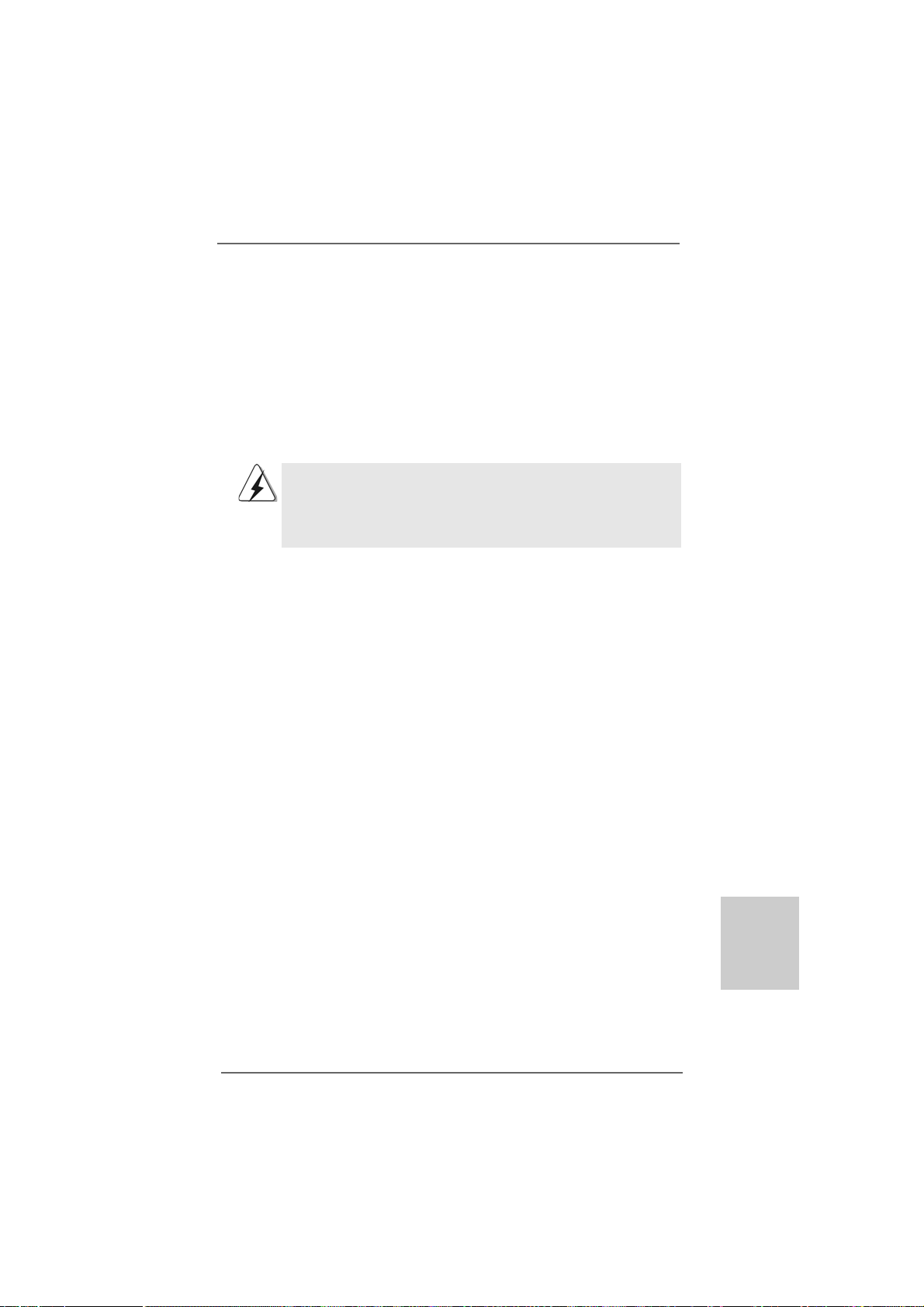
2. Installazione
Questa è una scheda madre con Form Factor ATX (12.0 pollici x 9.6 pollici; 30,5
cm x 24,4 cm). Prima di installare la scheda madre, studiare la configurazione del
telaio per assicurarsi che la scheda madre vi si adatti.
Precauzioni preinstallazionePrecauzioni preinstallazione
Precauzioni preinstallazione
Precauzioni preinstallazionePrecauzioni preinstallazione
Leggere le seguenti precauzioni prima di installare componenti delle
schede madri o di cambiare le impostazioni delle schede madri.
Prima di installare o rimuovere qualsiasi componente, assicurarsi che
l’alimentazione sia disattiva e che il cavo d’alimentazione sia scollegato dalla
presa di corrente. Diversamente si causeranno gravi danni alla scheda madre,
alle periferiche e/o ad altri componenti.
1. Togliere il cavo dalla presa elettrica prima di toccare le
componenti. In caso contrario la schedamadre, le periferiche,
e/o i componenti possono subire gravi danni.
2. Per evitare che l’elettricità statica danneggi la scheda madre,
NON appoggiare la scheda madre su moquette, tappeti o
tessuti simili. Ricordarsi di indossare un braccialetto
antistatico collegato a terra o di toccare un oggetto
posizionato a terra prima di maneggiare le componenti.
3. Tenere i componenti per i bordi e non toccare i ICs.
4. Ogni volta che si disinstalla un componente, appoggiarlo su
un tappetino antistatico messo a terra o depositarlo nella
borsa data in dotazione con il componente.
5. Nell’usare i giraviti per fissare la scheda madre al telaio non
serrare eccessivamente le viti! Altrimenti si rischia di
danneggiare la scheda madre.
ASRock 880G Pro3 Motherboard
9393
93
9393
ItalianoItaliano
ItalianoItaliano
Italiano
Page 94
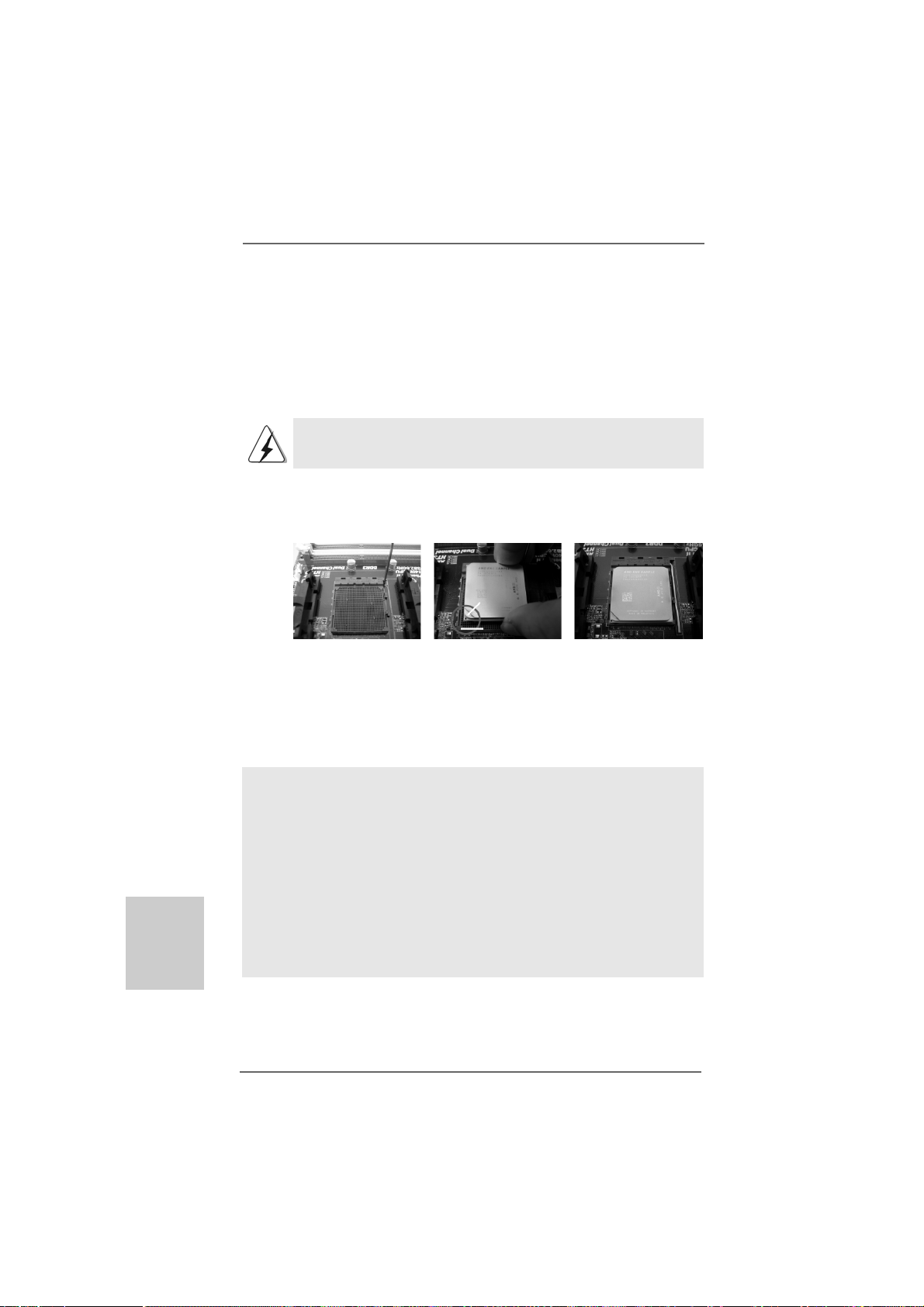
2.1 Installazione del processore2.1 Installazione del processore
2.1 Installazione del processore
2.1 Installazione del processore2.1 Installazione del processore
Step 1. Aprire lo zoccolo sollevando la leva da un angolo di 90°.
Step 2. Posizionare la CPU direttamente sopra la presa in modo tale che l’angolo
della CPU con il triangolo dorato corrisponda all’angolo della presa con il
triangolino.
Step 3. Inserire con cautela il processore nello zoccolo finché si adatta
perfettamente.
Il processore ha un solo corretto orientamento. NON forzare il
processore nello zoccolo: i pin potrebbero stortarsi.
Step 4. Quando il processore è posizionato, premere con decisione sullo zoccolo
mentre si abbassa la leva dello zonnettore per fissare il processore.
Quando la leva fa clic sulla linguetta laterale significa che è bloccata.
Levetta
sollevata di
90°
FASE 1:
Sollevare la levetta socket
2.22.2
Installazione della ventolina e del dispersore di caloreInstallazione della ventolina e del dispersore di calore
2.2
Installazione della ventolina e del dispersore di calore
2.22.2
Installazione della ventolina e del dispersore di caloreInstallazione della ventolina e del dispersore di calore
CPUCPU
CPU
CPUCPU
Triangolo dorato
CPU
Triangolino angolo
socket
FASE 2 / FASE 3:
Far corrispondere il triangolo
dorato della CPU al triangolino
nell’angolo del socket
FASE 4:
Abbassare e bloccare la
levetta socket
Italiano
ItalianoItaliano
ItalianoItaliano
9494
94
9494
Dopo avere installato la CPU sulla scheda madre, è necessario installare un
dispersore di calore ed una ventolina per dissipare il calore. È anche
necessario applicare del grasso termico tra la CPU ed il dispersore di calore
per migliorare la dissipazione del calore. Assicurarsi che la CPU ed il
dispersore di calore siano fissati in modo appropriato e che ci sia una
buona aderenza tra i due. Quindi collegare la ventolina CPU al connettore
PU FAN (CPU_FAN1, fare riferimento a pagina 2, Numero 6 o CPU_FAN2,
fare riferimento a pagina 2, Numero 5). Per eseguire un’installazione
appropriata, fare riferimento al manuale d’istruzioni della ventolina CPU e del
dispersore di calore.
ASRock 880G Pro3 Motherboard
Page 95

2.3 Installazione dei moduli di memoria (DIMM)2.3 Installazione dei moduli di memoria (DIMM)
2.3 Installazione dei moduli di memoria (DIMM)
2.3 Installazione dei moduli di memoria (DIMM)2.3 Installazione dei moduli di memoria (DIMM)
La scheda madre 880G Pro3 fornisce quattro alloggiamenti DIMM DDR3 (Double
Data Rate 3) a 240 pin, e supporta la tecnologia Dual Channel Memory. Per la
configurazione a due canali, è necessario installare sempre coppie identiche
(stessa marca, velocità, dimensioni e tipo di chi p) di DIMM DDR3 negli alloggiamenti
dello stesso colore. In altre parole, è necessario installare coppie identiche di DIMM
DDR3 nel canale doppio A (DDR3_A1 e DDR3_B1; alloggiamenti blu; vedere pag. 2
Nr. 8) oppure coppie identiche di DIMM DDR3 nel canale doppio B (DDR3_A2 e
DDR3_B2; alloggiamenti bianco; vedere pag. 2 Nr. 9), per fare sì che la tecnologia
Dual Channel Memory possa essere attivata. Questa scheda madre consente
anche di installare quattro DIMM DDR3 per la configurazione a canale doppio.
Questa scheda madre consente anche di installare quattro DIMM DDR3 per
configurazione a canale duale, si raccomanda di installare DIMM DDR3 identiche
nei quattro alloggiamenti. Consultare la Tabella configurazione Memoria Canale
Duale di seguito.
Configurazioni Dual Channel Memory
DDR3_A1 DDR3_A2 DDR3_B1 DDR3_B2
(alloggia mento (alloggiamento (alloggiamento (alloggiamento
blu) bianco) blu) bianco)
(1) Popolato - Popolato (2) - Popolato - Popolato
(3) Popolato Popolato Popolato Popolato
* Per la configurazione (3), installare DDR3 DIMM identici nei quattro slot.
1. Se si vogliono installare due moduli di memoria, per ottenere
compatibilità ed affidabilità ottimali, si raccomanda di installarli negli
alloggia menti dello stesso colore. In altre parole: in stallare i moduli di
memoria o nella serie di alloggiamenti blu (DDR3_A1 e DDR3_B1)
oppure nella serie di alloggiamenti bianco (DDR3_A2 e DDR3_B2).
2. Se negli alloggiamenti DIMM di questa scheda madre è installato un
solo modulo di memoria, oppure sono installati tre moduli di memoria,
è impossibile attivare la tecnologia Dual Channel Memory.
3. Se una coppia di moduli di memoria NON è installata nello stesso
“canale doppio”, ad esempio se si installa una coppia di moduli di
memoria su DDR3_A1 e DD3_A2, è impossibile attivare la
tecnologia Dual Channel Memory.
4. Non è consentito installare la DDR o DDR2 nello slot DDR3,
altrimenti si possono danneggiare questa scheda madre e la
DIMM.
5. Se si adottano moduli di memoria DDR3 1866/1800/1600 sulla
scheda madre, si consiglia di installarli sugli slot DDR3_A2 e
DDR3_B2.
ASRock 880G Pro3 Motherboard
9595
95
9595
ItalianoItaliano
ItalianoItaliano
Italiano
Page 96

Installare una DIMMInstallare una DIMM
Installare una DIMM
Installare una DIMMInstallare una DIMM
Scollegare l’alimentazione elettrica prima di aggiungere o rimuovere i
DIMM o altri componenti del sistema.
Step 1. Sbloccare lo slot DIMM premendo i fermi che lo trattengono verso
l’esterno.
Step 2. Allineare una DIMM sullo slot così che il pettine della DIMM combaci con
la sua sede sullo slot.
Italiano
ItalianoItaliano
ItalianoItaliano
9696
96
9696
La DIMM può essere montata correttamente soltanto con un
orientamento. Se si dovesse installare a forza la DIMM nello slot con
un orientamento errato, si causerebbero danni permanenti alla scheda
madre e alla DIMM stessa.
Step 3. Inserire saldamente la DIMM nello slot fino a far scattare completamente
in posizione i fermagli di ritegno alle due estremità e fino ad installare
correttamente la DIMM nella sua sede.
ASRock 880G Pro3 Motherboard
Page 97

2.42.4
Slot di espansione (Slot PCI ed Slot PCI Express)Slot di espansione (Slot PCI ed Slot PCI Express)
2.4
Slot di espansione (Slot PCI ed Slot PCI Express)
2.42.4
Slot di espansione (Slot PCI ed Slot PCI Express)Slot di espansione (Slot PCI ed Slot PCI Express)
Sulla scheda madre 880G Pro3 c’è 3 slot PCI ed 3 slot PCI Express.
Slot PCI: Sono utilizzati per installare schede di espansione con Interfaccia PCI
a 32-bit.
Slot PCI Express: L’alloggio PCIE1 (PCIE x1; bianco) è usato per le schede
PCI Express x1 lane, come schede Gigabit LAN, SATA2.
L’alloggio PCIE2 (PCIE x16; blu) è usato per le
schede grafiche PCI Express x16 lane, oppure è usato per
installare schede grafiche PCI Express per supportare la
funzione CrossFireXTM.
L’alloggio PCIE3 (PCIE x16; blu) è usato per le schede
PCI Express x4 lane, oppure è usato per installare schede
grafiche PCI Express per supportare la funzione
CrossFireXTM.
1. Se si intende installare una sola scheda PCI Express VGA su questa
scheda madre, installarla nell’alloggio PCIE2.
2. In modalità CrossFireXTM, installare le schede video PCI Express x16
negli alloggi PCIE2 e PCIE3.
3. Collegare una ventola chassis al relativo connettore della scheda
madre (CHA_FAN1, CHA_FAN2 o CHA_FAN3) quando si usano più
schede video per ottenere un migliore ambiente termico.
Installare una scheda di espansioneInstallare una scheda di espansione
Installare una scheda di espansione
Installare una scheda di espansioneInstallare una scheda di espansione
Step 1. Prima d’installare la scheda di espansione, assicurarsi che l’alimentazione
sia stata esclusa oppure che il cavo di alimentazione sia scollegato. Prima
di iniziare l’installazione, si prega di leggere la documentazione della scheda
di espansione e di effettuare le necessarie impostazioni del hardware.
Step 2. Rimuovere i ga nci sullo slot che si intende utilizzare. Tenere a portata di mano
le viti.
Step 3. Allineare il connettore della scheda con lo slot e premere con decisione
finché la scheda è completamente inserita nello slot.
Step 4. Agganciare la scheda allo chassis con le viti.
ASRock 880G Pro3 Motherboard
9797
97
9797
ItalianoItaliano
ItalianoItaliano
Italiano
Page 98

TMTM
TM
2.52.5
Guida al funzionamento di AGuida al funzionamento di A
2.5
Guida al funzionamento di A
2.52.5
Guida al funzionamento di AGuida al funzionamento di A
TMTM
TM
CrossFireXCrossFireX
CrossFireX
CrossFireXCrossFireX
La scheda madre supporta la funzione ATITM Hybrid CrossFireXTM. ATITM Hybrid
CrossFireXTM fornisce le funzionalità delle prestazioni multi-GPU consentendo al
processore grafico AMD 880G integrato e al processore grafico discreto di
funzionare contemporaneamente con l’uscita combinata su un solo monitor per
aumentare la velocità dei fotogrammi. Al momento, la tecnologia ATITM Hybrid
CrossFireXTM è supportata solamente dal sistema operativo Windows® VistaTM / 7,
e non è disponibile con il sistema operativo Windows® XP. In futuro, ATITM Hybrid
CrossFireXTM potrebbe essere supportata anche dal sistema operativo Windows
XP. Per le informazioni aggiornato visitate il nostro sito internet. Per le procedure di
installazione dettagliate e per conoscere le schede grafiche PCI Express
compatibili, fare riferimento alla pagina 20.
2.62.6
Guida operativa per CrossFireXGuida operativa per CrossFireX
2.6
Guida operativa per CrossFireX
2.62.6
Guida operativa per CrossFireXGuida operativa per CrossFireX
CrossFireXCrossFireX
CrossFireX
CrossFireXCrossFireX
Questa scheda madre supporta la funzione CrossFireXTM e Quad CrossFireXTM.
La tecnologia CrossFireXTM offre i mezzi più vantaggiosi possibile per combinare
più GPU (Graphics Processing Unit) ad altre prestazioni in un singolo PC.
Combinando una serie di diverse modalità operative con la progettazione software
intuitiva ed un meccanismo d’interconnessione innovativo, CrossFireXTM abilita il
massimo livello possibile di prestazioni e qualità d’immagine in qualsiasi
applicazione 3D. Correntemente la funzione CrossFireXTM è supportata solo dai
sistemi operativi Windows® XP con Service Pack 2 / VistaTM / 7. La funzione Quad
CrossFireXTM è supportata solo dal sistema operativo Windows® VistaTM / 7.
Visitare il sito AMD per gli aggiornamenti dei driver ATITM CrossFireXTM. Attenersi
alle procedure d’installazione, a pagina 22, per i dettagli.
TMTM
TMTM
TM
TMTM
TMTM
TITI
TI
TITI
TMTM
TM
TMTM
Hybrid Hybrid
Hybrid
Hybrid Hybrid
e Quad e Quad
e Quad
e Quad e Quad
®
Italiano
ItalianoItaliano
ItalianoItaliano
9898
98
9898
ASRock 880G Pro3 Motherboard
Page 99

2.7 Setup dei Jumpers2.7 Setup dei Jumpers
2.7 Setup dei Jumpers
2.7 Setup dei Jumpers2.7 Setup dei Jumpers
L’illustrazione mostra come sono settati i jumper.
Quando il ponticello è posizionato sui pin, il jumper
è “CORTOCIRCUITATO”. Se sui pin non ci sono
ponticelli, il jumper è “APERTO”. L’illustrazione
mostra un jumper a 3 pin in cui il pin1 e il pin2 sono
“CORTOCIRCUITATI” quando il ponticello è
posizionato su questi pin.
Jumper Settaggio del Jumper
Resettare la CMOS
(CLRCMOS1)
(vedi p.2 item 28)
Nota: CLRCMOS1 permette di cancellare i dati presenti nel CMOS. I dati del CMOS
comprendono le informazioni di configurazione quali la password di sistema,
data, ora, e i parametri di configurazione del sistema. Per cancellare e
ripristinare i parametri del sistema, spegnere il computer e togliere il cavo di
alimentazione dalla presa di corrente. Dopo aver lasciato trascorrere 15
secondi, utilizzare un cappuccio jumper per cortocircuitare i pin 2 e 3 su
CLRCMOS1 per 5 secondi. Dopo aver cortocircuitato il jumper Clear CMOS
jumper, togliere il terminatore jumper. Non cancellare la CMOS subito dopo
aver aggiornato il BIOS. Se è necessario cancellare la CMOS una volta
completato l’aggiornamento del BIOS, è necessario riavviare prima il sistema,
e poi spegnerlo prima di procedere alla cancellazione della CMOS.
Impostazione
predefinita
CORTOCIRCUIT ATO APERT O
Azzeramento
CMOS
ASRock 880G Pro3 Motherboard
9999
99
9999
ItalianoItaliano
ItalianoItaliano
Italiano
Page 100
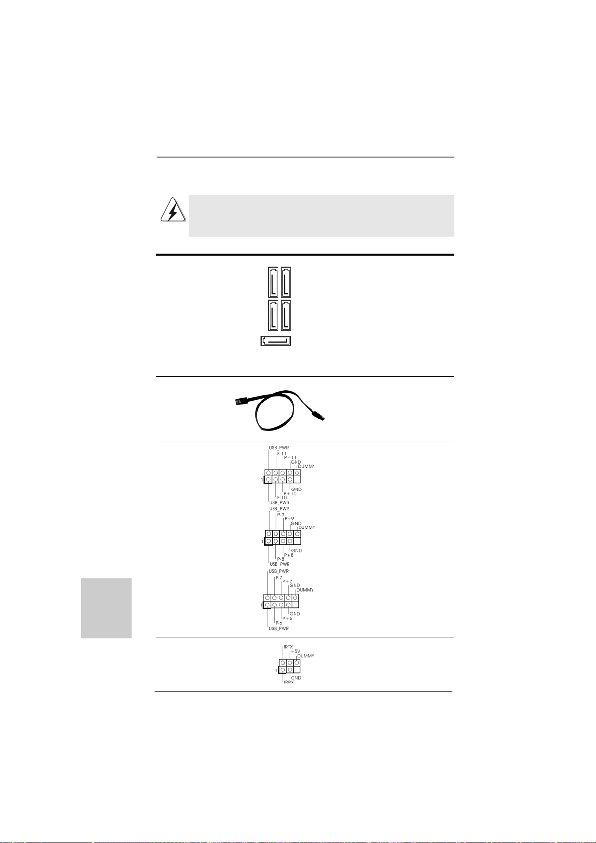
2.8 Connettori2.8 Connettori
2.8 Connettori
2.8 Connettori2.8 Connettori
I connettori NON sono jumpers. NON COLLOCARE i ponticelli sui
connettori. Installando dei cappucci a ponticello sui connettori si
causeranno danni permanenti alla scheda madre!
Connettori Descrizione dei connettori
Connettori Serial ATA3 Questi cinque connettori Serial
(SAT AIII_1: vedi p.2 Nr . 17) ATA3 (SATA3) supportano cavi
(SAT AIII_2: vedi p.2 Nr . 16) dati SATA per dispositivi di
(SAT AIII_3: vedi p.2 Nr . 14) immagazzina mento interni.
(SAT AIII_4: vedi p.2 Nr . 15) ATA3 (SATA3) supportano cavi
(SAT A3_5: vedi p.2 Nr . 18) SATA per dispositivi di memoria
SAT AIII_1 SA T AIII_3
SAT AIII_2 SA T AIII_4
SAT A3_5
interni. L’interfaccia SATA3
attuale permette velocità di
trasferimento dati fino a
6.0 Gb/s.
Cavi dati Serial ATA (SATA) Una o altra estremità del cavo
(Opzionale) di dati SATA può essere
collegata al disco rigido SATA3
o al connettore di SATA3 su
questa cartolina base.
Collettore USB 2.0 Oltre alle quattro porte USB 2.0
(9-pin USB10_11) predefinite nel pannello I/O, la
(vedi p.2 No. 27) scheda madre dispone di
tre intestazioni USB 2.0.
Ciascuna intestazione USB 2.0
(9-pin USB8_9) supporta due porte USB 2.0.
(vedi p.2 No. 29)
Italiano
ItalianoItaliano
ItalianoItaliano
100100
100
100100
(9-pin USB6_7)
(vedi p.2 No. 30)
Collettore modulo infrarossi Questo collettore supporta
(5-pin IR1) moduli ad infrarossi optional
(vedi p.2 Nr. 32) per la trasmissione e la
ricezione senza fili.
ASRock 880G Pro3 Motherboard
 Loading...