

Asko TD70 Service Manual

Service Manual
Tumble Dryer - TD70


Updates ..................................................................................................................................................................................................................................................4
Introduction ......................................................................................................................................................................................................................................... 5
Troubleshooting strategy ..............................................................................................................................................................................................................6
Product overview .............................................................................................................................................................................................................................7
Technical data ......................................................................................................................................................................................................................................9
Component descriptions ..........................................................................................................................................................................................................10
Components and measurement values ...................................................................................................................................................................... 10
Components and function description ........................................................................................................................................................................ 12
Control unit ...................................................................................................................................................................................................................................... 16
Circuit diagram TD70.1 ........................................................................................................................................................................................................ 16
Circuit diagram TD70.2 ........................................................................................................................................................................................................ 18
Circuit diagram TD70.2 HP ................................................................................................................................................................................................ 20
Circuit diagram TD70.2 HWC .........................................................................................................................................................................................22
Circuit diagram TD70.3 ........................................................................................................................................................................................................ 24
Troubleshooting .............................................................................................................................................................................................................................. 26
Fault indicators TD70.1 ......................................................................................................................................................................................................... 26
Fault indicators TD70.2 ......................................................................................................................................................................................................... 27
Fault indicators TD70.3 ......................................................................................................................................................................................................... 29
Other faults ................................................................................................................................................................................................................................. 30
Service menu and settings ........................................................................................................................................................................................................32
Service menu TD70.1 ............................................................................................................................................................................................................32
Service menu TD70.2 ............................................................................................................................................................................................................34
Service menu TD70.3 ............................................................................................................................................................................................................36
Settings ........................................................................................................................................................................................................................................... 38
Activating heating element 2 TD70.1 .................................................................................................................................................................... 38
Activating heating element 2 TD70.2 .................................................................................................................................................................... 38
Activating heating element 2 TD70.3 .................................................................................................................................................................... 38
Store program ...................................................................................................................................................................................................................... 38
Service and installation
Removing top plate and rear panel ............................................................................................................................................................................. 39
Replacing the panel and the control unit ..................................................................................................................................................................41
Transporting a tumble dryer with a heat pump .................................................................................................................................................... 43
Tumble Dryer TD70
Service Manual
Contents
Updates
Rev Date Description Initials
01 2011-09-06 First version FH
02 2011-10-03 BRAND OTHER included FH
03 2011-10-20 New document structure FH
04 2012-01-20 New revision circuit diagram EH
05 2012-05-03 Changed the info about Autofilter BPA
06 2012-05-04 Updated part no control units, irrelevant articles deleted. EH
07 2012-07-05 Troubleshooting TD70 HP, LCD F29, removing back rear included. EH
Service Manual TD70
4
Introduction
You are holding the service manual for TD70 tumble dryers. It should be easy to service a tumble
dryer. It is important that you, as a service technician, are provided the necessary conditions to
work in an efficient and satisfactory manner. Our hope is that this Service & Training Guide is a
useful tool for your daily work.
Asko Appliances AB
SE-534 82 Vara
Sweden
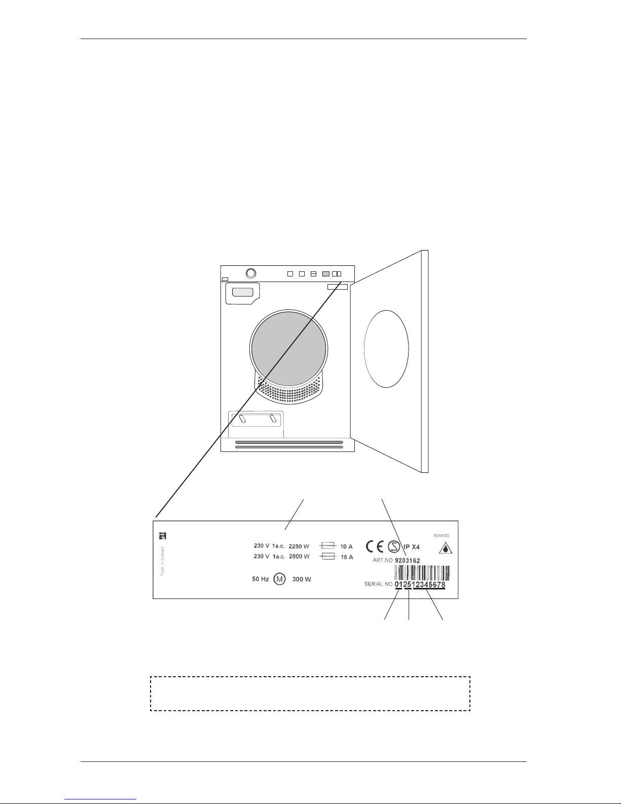
The type designation can be found on the machine plate, which is located on the inside of the
front panel by the door catch (see image below).
Type designation
Product number
TYPE TD70.3
Serial number
Year
Week
OPERATING INSTRUCTIONS
Always have the operating instructions for the machine available during service
Service Manual TD70
5
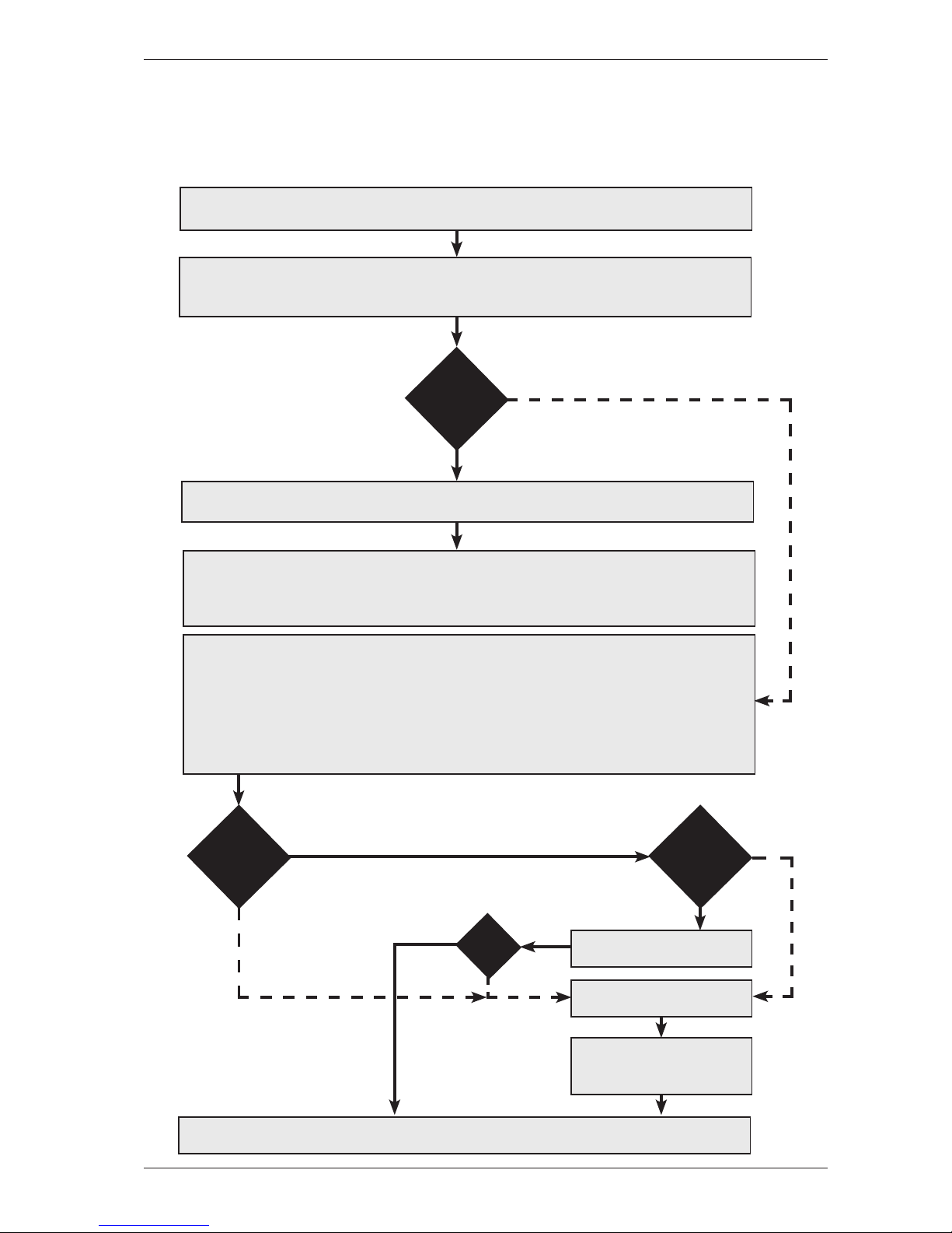
Troubleshooting strategy
Troubleshooting is an important part of the service callout, and as such we have drawn up a
troubleshooting strategy that describes, in broad terms and step by step, what you need to do to find
and diagnose faults arising in our machines.
• Ask the customer to describe the problem.
• Check whether the customer’s description matches the reported fault.
• Check that the machine is correctly installed:
- Electrical connection - Drainage
- Water connection - Machine correctly levelled
Fault
found?
Incorrect installation or external factors that affect performance and functionality (for
example, water pressure, electrical supply, drainage).
The machine operates normally. No deviations can be found. The customer probably
needs to be informed about proper use of the machine. If necessary, also inform the
customer about the warranty conditions and the fact that the customer will be charged
for the service call.
Yes
Open the ser vice menu:
1. Check the settings
2. Run a test cycle
3. Note any fault codes
If the above actions do not uncover the fault:
• Conduct general troubleshooting. Use the documentation available at ServiceSaver
(service manuals, service memos, wiring diagrams and other documents).
Yes
No
No
Fault
diagnosed?
Repair and check
function/safety.
Carry out the actions
suggested by technical
support.
Satisfied customer!
OK?
No
Yes
No
Yes
Fault
found?
Contact technical support
for assistance.
Service Manual TD70
6
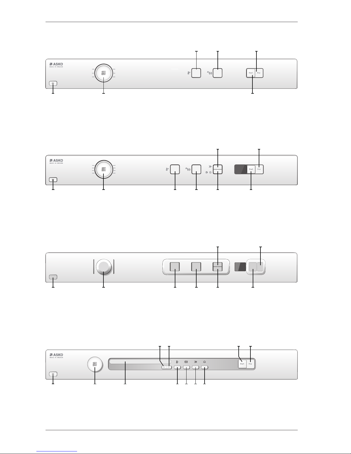
Product overview
Programs: 6
Options: 5
Settings: 1
TD70.1, Paneltype B - (BRAND ASKO)
/
J1 S9S4S3S1 S10
S7 S11
Programs: 4
Options: 2
Settings: 1
TD70.1, Paneltype A - (BRAND ASKO)
J1S1
S10
S7S4 S11
Programs: 6-15
Options: 5
Settings: 1
TD70.2 - (BRAND ASKO)
S3 S9
J1 S4 S6 S7S5DISPLAY
S2 S8
S1
Programs: 6
Options: 5
Settings: 1
TD70.1 - (BRAND OTHER)
J1 S9S4S3S1 S10
S7 S11
Service Manual TD70
7

Product overview
Programs: 10, plus settings menu
Options: 5
Settings: 4
TD70.3
S1 S3DISPLAY1 DISPLAY2 DISPLAY3
J1 S2
TD70.3 (Integrerad)
Programs: 10, plus settings menu
Options: 5
Settings: 4
S1 S3
DISPLAY1 DISPLAY2 DISPLAY3
S5 S2
S4
Programs: 6-15
Options: 5
Settings: 1
TD70.2 - (BRAND OTHER)
S3 S9
J1 S4 S6 S7S5DISPLAY
S2 S8
S1
Service Manual TD70
8
Technical information
Height 850 mm
Width 595 mm
Depth 585 mm
Weight 43 kg (Vented)
47 kg (Condenser)
55 kg (Heat pump)
44 kg (Heating Water Circuit)
Cylinder volume 112 litres
Capacity EU 7.0 kg
US/AU 7.0 kg
Speed 50-55 rpm
Connection 1-phase 230 V, 50/60 Hz, (10 A/16 A) **
Rated power 1950 W = 10 A** (Vented/Condenser)
3000 W = 16 A** (Vented)
2500 W = 16 A** (Condenser)
1300 W = 10 A** (Heat pump)
1950 W = 10 A** (Heating Water Circuit)
The control buttons are used to switch between 10 A and 16 A via the software.
Does not apply to Heat Pump or Heating Water Circuit.
Drum material Stainless steel
Outer panels Powder-coated and hot-galvanised sheet steel or stainless steel
Installation Stacked or freestanding
Protection class IP X4
** See type plate.
Technical data
Energy consumption and program times
See the operating instructions for information on energy consumption and program times.
Service Manual TD70
9
Component description
Components and measurement values
The specified resistance values apply at room temperature (about 20°C/68°F). Values within
±10% are considered normal.
Article no. Component Measurement value Comment
80 839 15 Motor 50 Hz,
220/240 V
Winding resistance:
cable colour red-white 26.5 Ω
cable colour red-blue 53.5 Ω
cable colour white-blue 27.0 Ω
Current: 0.7 A; 140 W; 2850 rpm
80 839 16 Motor 60 Hz,
220/240 V
Winding resistance:
cable colour red-white 26.5 Ω
cable colour red-blue 53.5 Ω
cable colour white-blue 27.0 Ω
Current: 0.7 A; 140 W; 3300
rpm
The motor is a 2-pin motor and is
directly connected to the fan for
internal air and the gearing for driving
the cylinder. On condenser dryers, the
motor also drives the fan for ex ternal air.
80 903 13 Capacitor 8 μF 50 Hz
80 903 14 Capacitor 6 μF 60 Hz
80 902 70 Capacitor heat pump 17 μF 50 and 60 Hz
80 821 28 Condensate pump 50 Hz
80 846 48 Condensate pump 60 Hz
80 762 02 EMC-filter with inductor The filter eliminates inter ference to and
from the machine.
80 833 44 Thermistor 4.8 kΩ (at 25°C) The thermistor controls temperature
regulation. If the thermistor is shor tcircuited or detaches from the control
unit, the program is stopped.
80 902 72 Termostat 150 150°C manual reset
The thermostat /overheating cut-out
stops the program if the temperature
becomes too high.
80 902 73 Termostat 135 135°C manual reset
80 902 24 Thermostat 110 110°C automatic
80 761 04 Door switch The front door triggers a door switch
which stops the program when the door
is open. If the door has been opened and
closed during the program the machine
must be restarted using the Start/Stop
button.
Service Manual TD70
10
Component description
Article no. Component Measurement value Comment
80 761 03 Microswitch float
Overflow guard
If both containers in the tumble dryer
are full the program is stopped by a float
switch installed in the lower container.
“Over flow” is indicated on the display.
80 824 92 Heating element 1950 W Heater 1: 1950 W, 24.5 Ω
80 915 90 Heating element 2500 WHeater 1: 1950 W, 24.5 Ω
Heater 2: 550 W, 91.4 Ω
80 824 91 Heating element 3000 WHeater 1: 1950 W, 24.5 Ω
Heater 2: 1050 W, 45.5 Ω
80 821 22 Base heat pump
complete
50 Hz
80 821 23 Base heat pump
complete
60 Hz
80 88 415 Reversing valve 1.9 kΩ
88 015 18
88 015 19
Control unit compl.
TD70.1 A
Control unit compl.
TD70.1 B
The control unit contains
microprocessors for controlling
programs, the motor, the heating
elements etc.
88 015 20
88 015 21
Control unit complete
TD70.2
Control unit complete
TD70.2 HP/HWC
88 015 00
88 015 01
Control unit complete
TD70.3
Control unit complete
TD70.3 FI
80 846 49 LED-light compl. LED-technology for the machine’s
internal light.
Service Manual TD70
11

Component descriptions
Components and function description
Here we describe the function and
specification of the most impor tant
components. Cer tain components are found
only in more highly specified machines or in
particular markets. See the Troubleshooting
chapter for fault and information codes.
CU (Control Unit)
The CU (Control Unit) functions as both a
control panel and a logic component. The
control panel is equipped with knobs/buttons
for selecting programs, Start/Stop buttons and
a display. It is an integrated part of the CU
and cannot be replaced separately. The logic
component manages functions needed for
drying programs and diagnosis. The CU has an
internal power supply for the logic component.
In the event of a fault, the CU can diagnose
a number of components and functions, and
a total of 4 fault codes can be displayed. To
facilitate troubleshooting there is a component
testing function in which the outputs are
activated according to a special sequence.
Power supply
Mains voltage, built-in internal voltage
converter for the logic component.
Light
Certain machines have an internal light
that is activated when the door is opened.
LED technology is used to improve energy
efficiency.
Thermistors
The thermistors are of the NTC type (Negative
Temperature Coefficient), which means their
resistance decreases as temperature increases.
Thermistor 1 is in the air duct on the front frame,
after the internal impeller. If there is an interruption
in the thermistor circuit or if it short circuits, the
drying program stops and the display shows
“Thermistor fault”.
Purpose: Measures the temperature of the air that
has passed the load and controls the drying process
and the heating element.
Thermistor 2 is on condenser dryers located after the
condenser and on heat pump dryers located on the
evaportator pipe by the comperssor.
Purpose: Measures the temperature of the
dehumidified air, the value of which is used as a
parameter in the drying process.
Resistance values for thermistors 1 and 2
Temperature Resistance
20°C 5989
25°C 4869
30°C 3946
35°C 3197
40°C 2598
45°C 2126
50°C 1758
55°C 1471
60°C 1240
65°C 1043
70°C 857
Tolerance : ±1%
Service Manual TD70
12
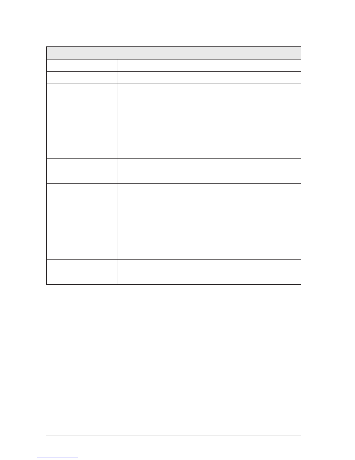
Thermostat and overheating cut-out
The thermostat is installed next to the heating
element and is used to reduce the element output
by turning it off if the ambient temperature
exceeds 135°C (±5°C) for condenser dryers and
110°C (±5°C) for others.
The machine is equipped with a overheating
cut-out, which is available in two versions, one
automatically resettable and one manual. The
overheating cut-out switches off the power supply
to all components if the temperature exceeds
150°C (±5°C) and closes the circuit once the
temperature drops below 135°C (±8°C). The
drying program stops and must be restarted if the
overheating cut-out is triggered.
To reset the manual overheating cut-out,
the cover plate on the machines back must be
removed. Press the button on the overheating cutout for manual reset. The automatic overheating
cut-out resets when the temperature drops below
135°C (±8°C) for condenser dryer and 120°C
(±5°C) for others.
Purpose: The thermostat measures
temperature and controls heating element
output. The overheating cut-out controls the
temperature and cuts the power supply if the
machine overheats.
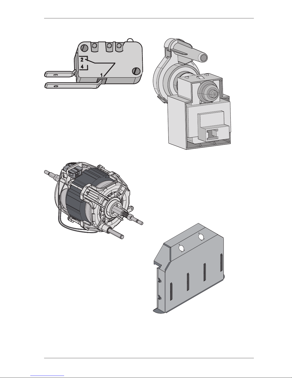
Cover plate (658 x 483 mm)
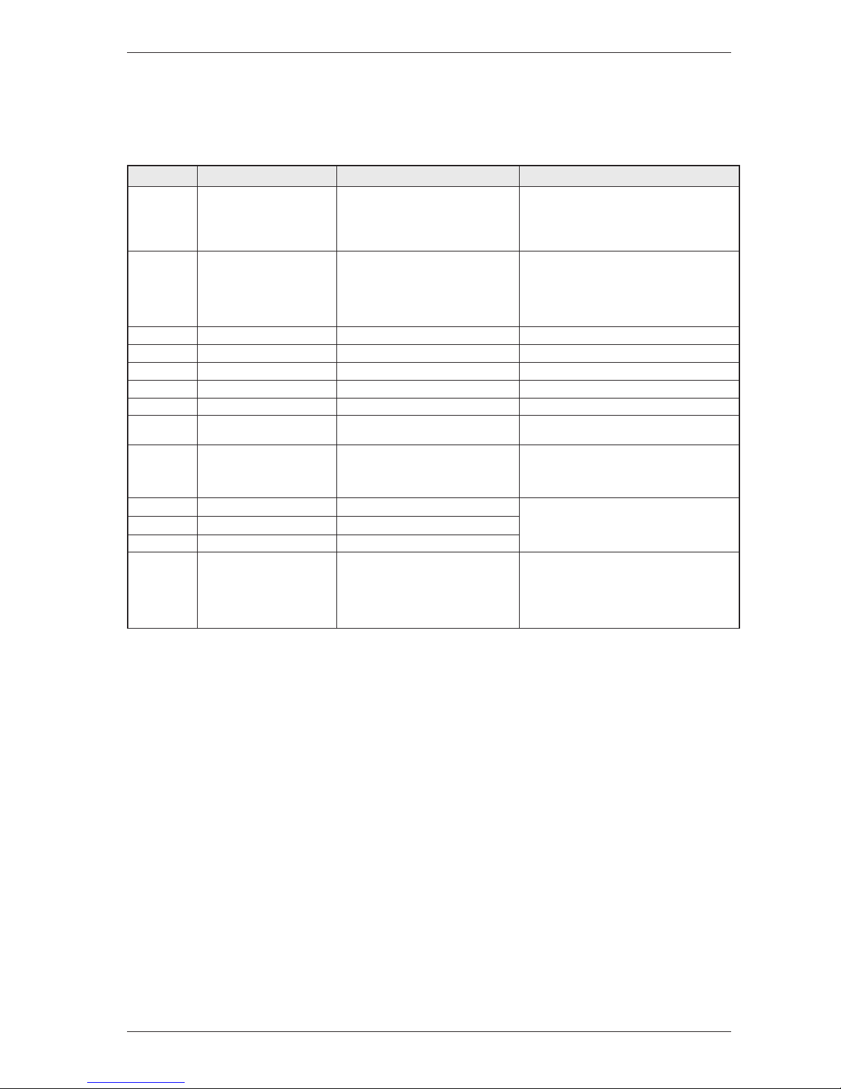
EMC filter
The filter is installed next to the cable fasteners
where the connection cable enters the
machine. The filter consists of a number of coils,
condensers and resistors.
Purpose: To eliminate electromagnetic
interference to and from the machine.
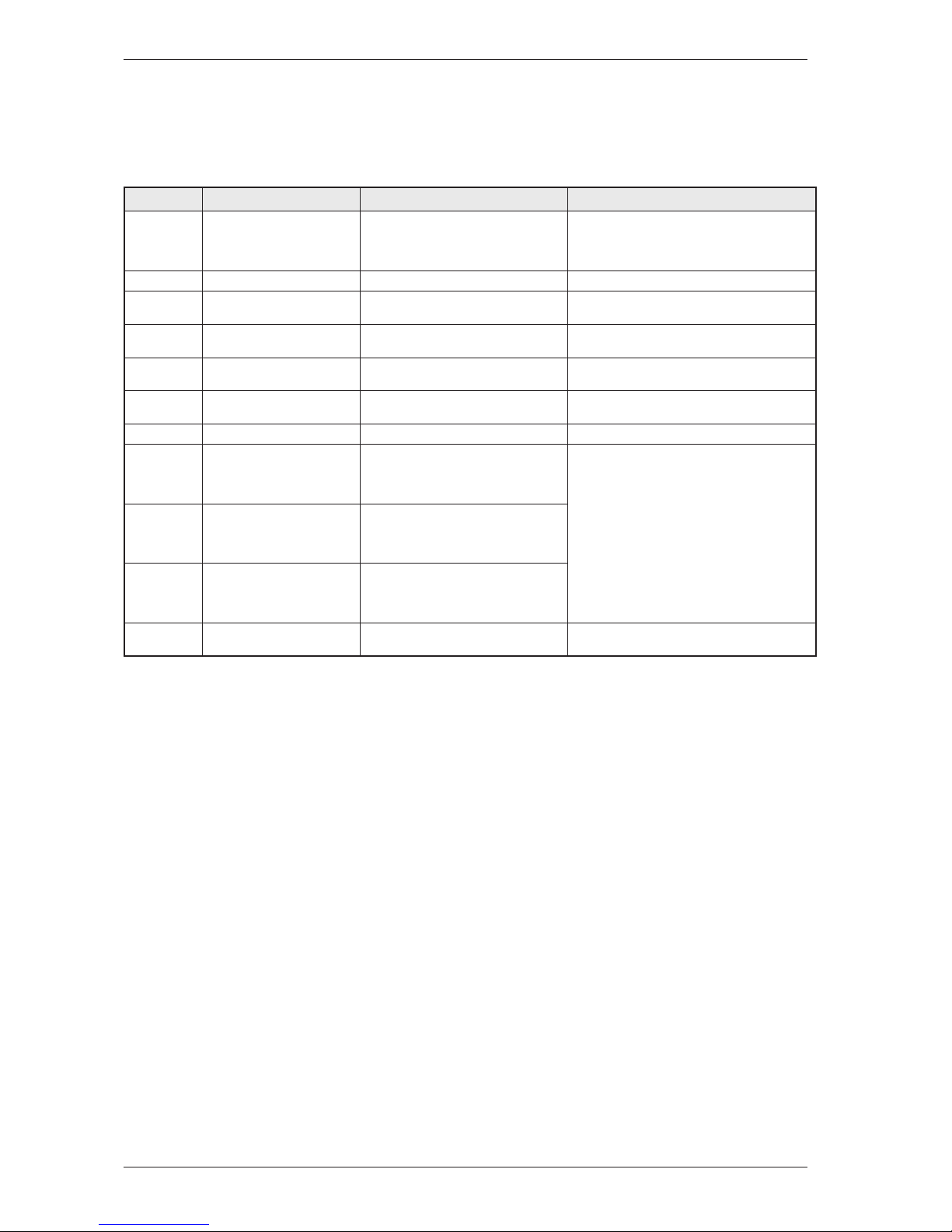
Overflow guard
The overflow guard comprises a microswitch
triggered by a float. When the lower condensed
water container becomes full the float rises and
triggers the microswitch. The microswitch is
normally closed; when activated it opens the
circuit. When the microswitch has been open
for more than 30 seconds, the drying program
stops and the display shows “Over flow”. You
can erase this message by turning the program
selector or pressing the Start/Stop buttons.
Purpose: To provide protection from any
water leaks or flooding from the machine.
Component descriptions
Thermostat
Overheating cut-out
Reset
Service Manual TD70
13
Component descriptions
Door switch
The door switch is located in a holder in the
middle of the front support and is activated by
a pin in the front door. The switch is normally
open and closes when the door is closed. If the
front door is opened during operation the CU
stops the drying program. The program starts
from the beginning if restarted.
Purpose: To prevent the machine from running
while the door is open.
Drying motor
The motor is at the bottom and drives the
impeller that is directly fitted to the shaft
journal. The motor is a unit with a belt
tensioner and springs and drives the drying
drum via a poly V-belt.
Purpose: To drive the impeller and drum during
the drying process.
Drainage pump (condenser dryer)
The drainage pump is located in the lower
condensed water container. The condensed
water is pumped to the condensed water
container or directly to the drain. When a
drying program is running, the drainage pump
is activated constantly in cycles of 30 seconds
ON and 210 seconds OFF.
Purpose: To pump condensed water to the
condensed water container or the drain.
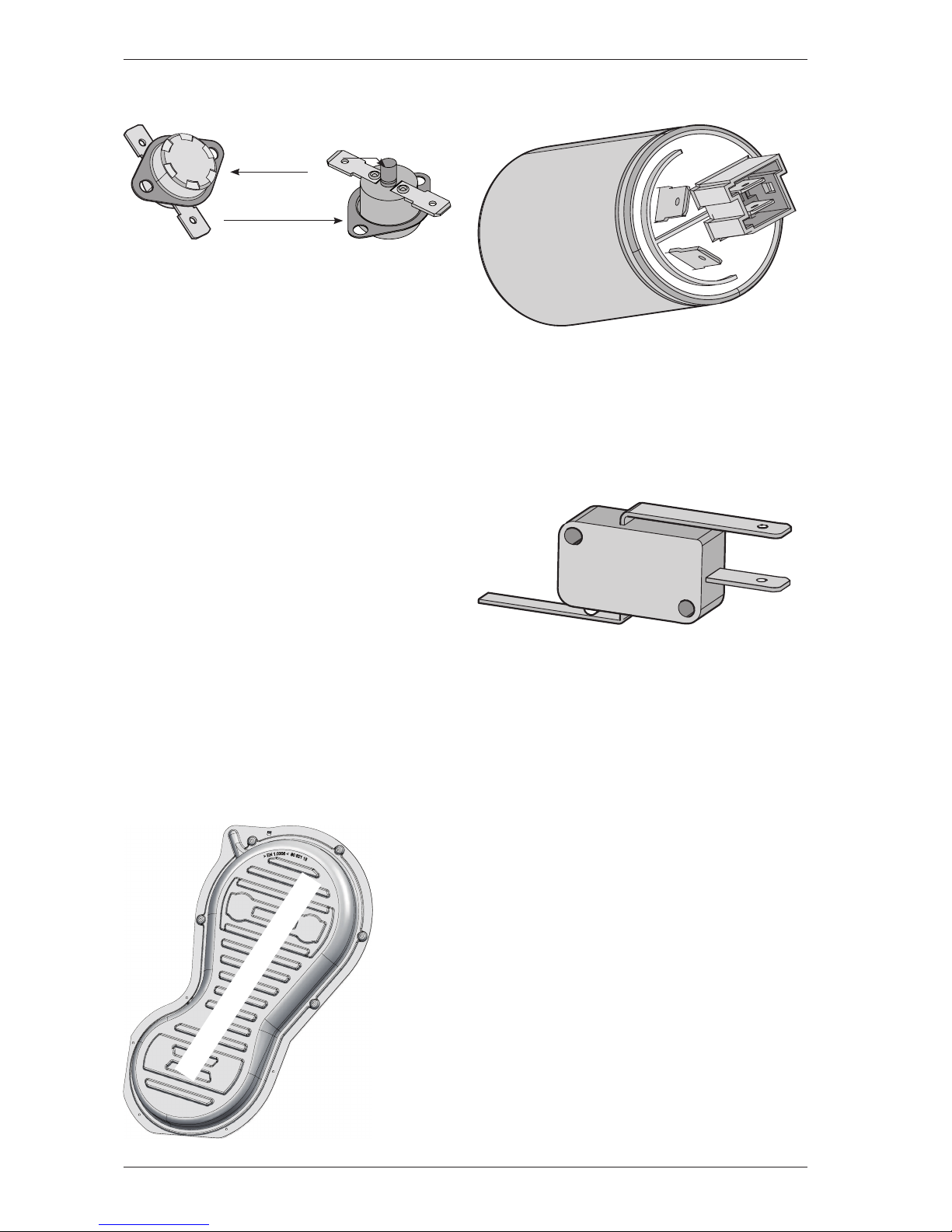
Heating element
The heating element is located in the rear section
and consists of two separate heating coils. Each
heating coil is made from resistance wire.
Purpose: To heat the drying air to the right
temperature.
Service Manual TD70
14
 Loading...