

Page 1

RTM-ATCA-736X-DD
Installation and Use
P/N: 6806800L82C
June 2014
Page 2

©
Copyright 2014 Artesyn Embedded Technologies, Inc.
All rights reserved.
Trademarks
Artesyn Embedded Technologies, Artesyn and the Artesyn Embedded Technologies logo are trademarks and service marks of
Artesyn Embedded Technologies, Inc.© 2014 Artesyn Embedded Technologies, Inc. All other product or service names are the
property of their respective owners.
Intel® is a trademark or registered trademark of Intel Corporation or its subsidiaries in the United States and other countries.
Java™ and all other Java-based marks are trademarks or registered trademarks of Oracle America, Inc. in the U.S. and other countries.
Microsoft®, Windows® and Windows Me® are registered trademarks of Microsoft Corporation; and Windows XP™ is a trademark of
Microsoft Corporation.
PICMG®, CompactPCI®, AdvancedTCA™ and the PICMG, CompactPCI and AdvancedTCA logos are registered trademarks of the PCI
Industrial Computer Manufacturers Group.
UNIX® is a registered trademark of The Open Group in the United States and other countries.
Notice
While reasonable efforts have been made to assure the accuracy of this document, Artesyn assumes no liability resulting from any
omissions in this document, or from the use of the information obtained therein. Artesyn reserves the right to revise this document
and to make changes from time to time in the content hereof without obligation of Artesyn to notify any person of such revision or
changes.
Electronic versions of this material may be read online, downloaded for personal use, or referenced in another document as a URL to
an Artesyn website. The text itself may not be published commercially in print or electronic form, edited, translated, or otherwise
altered without the permission of Artesyn.
It is possible that this publication may contain reference to or information about Artesyn products (machines and programs),
programming, or services that are not available in your country. Such references or information must not be construed to mean that
Artesyn intends to announce such Artesyn products, programming, or services in your country.
Limited and Restricted Rights Legend
If the documentation contained herein is supplied, directly or indirectly, to the U.S. Government, the following notice shall apply
unless otherwise agreed to in writing by Artesyn.
Use, duplication, or disclosure by the Government is subject to restrictions as set forth in subparagraph (b)(3) of the Rights in
Technical Data clause at DFARS 252.227-7013 (Nov. 1995) and of the Rights in Noncommercial Computer Software and
Documentation clause at DFARS 252.227-7014 (Jun. 1995).
Contact Address
Artesyn Embedded Technologies Artesyn Embedded Technologies
Marketing Communications
2900 S. Diablo Way, Suite 190
Tempe, Arizona 85282
Lilienthalstr. 17-19
85579 Neubiberg/Munich
Germany
Page 3

Contents
Contents
About this Manual . . . . . . . . . . . . . . . . . . . . . . . . . . . . . . . . . . . . . . . . . . . . . . . . . . . . . . . . . . . . . . . . . . . . . . . 11
1 Introduction . . . . . . . . . . . . . . . . . . . . . . . . . . . . . . . . . . . . . . . . . . . . . . . . . . . . . . . . . . . . . . . . . . . . . . . . . 15
1.1 Overview . . . . . . . . . . . . . . . . . . . . . . . . . . . . . . . . . . . . . . . . . . . . . . . . . . . . . . . . . . . . . . . . . . . . . . . . . . 15
1.2 Advanced RTM Features . . . . . . . . . . . . . . . . . . . . . . . . . . . . . . . . . . . . . . . . . . . . . . . . . . . . . . . . . . . . . 15
1.3 I/O PICMG Standards Compliance . . . . . . . . . . . . . . . . . . . . . . . . . . . . . . . . . . . . . . . . . . . . . . . . . . . . 16
1.4 I/O Interfaces . . . . . . . . . . . . . . . . . . . . . . . . . . . . . . . . . . . . . . . . . . . . . . . . . . . . . . . . . . . . . . . . . . . . . . 16
1.4.1 Ports 1-2, Ethernet 1000Base-T (RJ-45) . . . . . . . . . . . . . . . . . . . . . . . . . . . . . . . . . . . . . . . . . 17
1.5 LEDs . . . . . . . . . . . . . . . . . . . . . . . . . . . . . . . . . . . . . . . . . . . . . . . . . . . . . . . . . . . . . . . . . . . . . . . . . . . . . . 17
1.6 Disk "Request Eject" Button . . . . . . . . . . . . . . . . . . . . . . . . . . . . . . . . . . . . . . . . . . . . . . . . . . . . . . . . . . 19
1.7 Reset Button . . . . . . . . . . . . . . . . . . . . . . . . . . . . . . . . . . . . . . . . . . . . . . . . . . . . . . . . . . . . . . . . . . . . . . . 19
1.8 Software Support . . . . . . . . . . . . . . . . . . . . . . . . . . . . . . . . . . . . . . . . . . . . . . . . . . . . . . . . . . . . . . . . . . . 19
1.9 Products Supported by this Manual . . . . . . . . . . . . . . . . . . . . . . . . . . . . . . . . . . . . . . . . . . . . . . . . . . . 20
1.10 Identification Labels . . . . . . . . . . . . . . . . . . . . . . . . . . . . . . . . . . . . . . . . . . . . . . . . . . . . . . . . . . . . . . . . 21
2 Installation . . . . . . . . . . . . . . . . . . . . . . . . . . . . . . . . . . . . . . . . . . . . . . . . . . . . . . . . . . . . . . . . . . . . . . . . . . 25
2.1 Overview . . . . . . . . . . . . . . . . . . . . . . . . . . . . . . . . . . . . . . . . . . . . . . . . . . . . . . . . . . . . . . . . . . . . . . . . . . 25
2.2 Installation and Removal of the Rear Transition Module . . . . . . . . . . . . . . . . . . . . . . . . . . . . . . . . . 25
2.3 Important Information about Your Chassis . . . . . . . . . . . . . . . . . . . . . . . . . . . . . . . . . . . . . . . . . . . . 25
2.3.1 Safety Statement . . . . . . . . . . . . . . . . . . . . . . . . . . . . . . . . . . . . . . . . . . . . . . . . . . . . . . . . . . . . 25
2.3.2 Observe Maximum Module Current Requirements . . . . . . . . . . . . . . . . . . . . . . . . . . . . . . . 25
2.4 Before You Install Or Remove the RTM . . . . . . . . . . . . . . . . . . . . . . . . . . . . . . . . . . . . . . . . . . . . . . . . 26
2.4.1 Observe ESD Precautions. . . . . . . . . . . . . . . . . . . . . . . . . . . . . . . . . . . . . . . . . . . . . . . . . . . . . . 26
2.4.2 Watch for Bent Pins or Other Damage . . . . . . . . . . . . . . . . . . . . . . . . . . . . . . . . . . . . . . . . . . 26
2.5 Use Caution When Installing or Removing RTM . . . . . . . . . . . . . . . . . . . . . . . . . . . . . . . . . . . . . . . . . 27
2.5.1 Preserve EMI Compliance . . . . . . . . . . . . . . . . . . . . . . . . . . . . . . . . . . . . . . . . . . . . . . . . . . . . . 27
2.5.2 Understand Hot Swap . . . . . . . . . . . . . . . . . . . . . . . . . . . . . . . . . . . . . . . . . . . . . . . . . . . . . . . . 27
2.6 Verify Slot Usage . . . . . . . . . . . . . . . . . . . . . . . . . . . . . . . . . . . . . . . . . . . . . . . . . . . . . . . . . . . . . . . . . . . 28
2.7 Installing the Advanced Rear Transition Module . . . . . . . . . . . . . . . . . . . . . . . . . . . . . . . . . . . . . . . . 28
2.8 Removing the Advanced Rear Transition Module . . . . . . . . . . . . . . . . . . . . . . . . . . . . . . . . . . . . . . . 30
2.9 Verifying the Hardware Installation . . . . . . . . . . . . . . . . . . . . . . . . . . . . . . . . . . . . . . . . . . . . . . . . . . . 31
2.10 SAS Drive Carrier Assembly Installation . . . . . . . . . . . . . . . . . . . . . . . . . . . . . . . . . . . . . . . . . . . . . . . . 32
2.11 SAS Drive Carrier Assembly Removal (Eject) . . . . . . . . . . . . . . . . . . . . . . . . . . . . . . . . . . . . . . . . . . . . 33
RTM-ATCA-736X-DD Installation and Use (6806800L82C)
3
Page 4

Contents
Contents
Contents
3 SAS RAID Details . . . . . . . . . . . . . . . . . . . . . . . . . . . . . . . . . . . . . . . . . . . . . . . . . . . . . . . . . . . . . . . . . . . . . 37
3.1 Overview . . . . . . . . . . . . . . . . . . . . . . . . . . . . . . . . . . . . . . . . . . . . . . . . . . . . . . . . . . . . . . . . . . . . . . . . . . 37
3.2 Hard Disk Drive Controller . . . . . . . . . . . . . . . . . . . . . . . . . . . . . . . . . . . . . . . . . . . . . . . . . . . . . . . . . . . 37
3.3 SAS Boot BIOS Features . . . . . . . . . . . . . . . . . . . . . . . . . . . . . . . . . . . . . . . . . . . . . . . . . . . . . . . . . . . . . 37
3.4 Brief Theory of BIOS Operation . . . . . . . . . . . . . . . . . . . . . . . . . . . . . . . . . . . . . . . . . . . . . . . . . . . . . . . 38
3.5 Boot BIOS Configuration Utility . . . . . . . . . . . . . . . . . . . . . . . . . . . . . . . . . . . . . . . . . . . . . . . . . . . . . . . 38
3.5.1 Launching the Boot BIOS Configuration Utility . . . . . . . . . . . . . . . . . . . . . . . . . . . . . . . . . . . 38
3.5.2 BIOS Launch: Main Menu . . . . . . . . . . . . . . . . . . . . . . . . . . . . . . . . . . . . . . . . . . . . . . . . . . . . . . 39
3.5.3 Adapter Properties Menu . . . . . . . . . . . . . . . . . . . . . . . . . . . . . . . . . . . . . . . . . . . . . . . . . . . . . 40
3.6 RAID Firmware Capability . . . . . . . . . . . . . . . . . . . . . . . . . . . . . . . . . . . . . . . . . . . . . . . . . . . . . . . . . . . . 40
3.6.1 BIOS, RAID Properties Menu . . . . . . . . . . . . . . . . . . . . . . . . . . . . . . . . . . . . . . . . . . . . . . . . . . . 41
3.6.2 BIOS, RAID Create New Array and Global Hot Spare. . . . . . . . . . . . . . . . . . . . . . . . . . . . . . . 42
4 Mechanical and Connector Information. . . . . . . . . . . . . . . . . . . . . . . . . . . . . . . . . . . . . . . . . . . . . . . . . 45
4.1 Specifications . . . . . . . . . . . . . . . . . . . . . . . . . . . . . . . . . . . . . . . . . . . . . . . . . . . . . . . . . . . . . . . . . . . . . . 45
4.1.1 Physical Dimensions . . . . . . . . . . . . . . . . . . . . . . . . . . . . . . . . . . . . . . . . . . . . . . . . . . . . . . . . . . 45
4.1.2 Weight . . . . . . . . . . . . . . . . . . . . . . . . . . . . . . . . . . . . . . . . . . . . . . . . . . . . . . . . . . . . . . . . . . . . . 45
4.1.3 Power Requirements . . . . . . . . . . . . . . . . . . . . . . . . . . . . . . . . . . . . . . . . . . . . . . . . . . . . . . . . . 45
4.1.4 Environmental Specifications and Compliance . . . . . . . . . . . . . . . . . . . . . . . . . . . . . . . . . . . 46
4.1.5 NEBS Compliance . . . . . . . . . . . . . . . . . . . . . . . . . . . . . . . . . . . . . . . . . . . . . . . . . . . . . . . . . . . . 47
4.1.6 Electromagnetic Compliance . . . . . . . . . . . . . . . . . . . . . . . . . . . . . . . . . . . . . . . . . . . . . . . . . 47
4.2 Connectors and Pin Assignments . . . . . . . . . . . . . . . . . . . . . . . . . . . . . . . . . . . . . . . . . . . . . . . . . . . . . 48
4.2.1 1000Base-T Ethernet Ports . . . . . . . . . . . . . . . . . . . . . . . . . . . . . . . . . . . . . . . . . . . . . . . . . . . . 49
4.2.2 Zone 3 Connectors . . . . . . . . . . . . . . . . . . . . . . . . . . . . . . . . . . . . . . . . . . . . . . . . . . . . . . . . . . . 50
4.2.2.1 Connector J30, Power Supply for Advanced RTM . . . . . . . . . . . . . . . . . . . . . . . . 51
4.2.2.2 Connector J30, Storage and Management Infrastructure Pin Assignments . 52
4.2.2.3 Connector J32, PCI-Express and Test Infrastructure Pin Assignments . . . . . . 53
5 IPMI Functions List . . . . . . . . . . . . . . . . . . . . . . . . . . . . . . . . . . . . . . . . . . . . . . . . . . . . . . . . . . . . . . . . . . . 57
5.1 Overview . . . . . . . . . . . . . . . . . . . . . . . . . . . . . . . . . . . . . . . . . . . . . . . . . . . . . . . . . . . . . . . . . . . . . . . . . . 57
5.2 IPMI and Management Controller (IPMC) . . . . . . . . . . . . . . . . . . . . . . . . . . . . . . . . . . . . . . . . . . . . . . 57
5.3 Sensor Data Records . . . . . . . . . . . . . . . . . . . . . . . . . . . . . . . . . . . . . . . . . . . . . . . . . . . . . . . . . . . . . . . 57
5.3.1 RTM E-Keying Port Assignments . . . . . . . . . . . . . . . . . . . . . . . . . . . . . . . . . . . . . . . . . . . . . . . 59
5.4 Supported IPMI Commands . . . . . . . . . . . . . . . . . . . . . . . . . . . . . . . . . . . . . . . . . . . . . . . . . . . . . . . . . . 60
4
RTM-ATCA-736X-DD Installation and Use (6806800L82C)
Page 5

Contents
5.4.1 Disk IPMI ’raw’ Commands . . . . . . . . . . . . . . . . . . . . . . . . . . . . . . . . . . . . . . . . . . . . . . . . . . . . 61
5.4.1.1 Disk Eject, Deactivation Request to Power-off Disk . . . . . . . . . . . . . . . . . . . . . . 62
5.4.1.2 Approve Disk Eject Request . . . . . . . . . . . . . . . . . . . . . . . . . . . . . . . . . . . . . . . . . . 62
5.4.1.3 Read OEM Manufacturing in DCA EEPROM . . . . . . . . . . . . . . . . . . . . . . . . . . . . . 63
5.4.1.4 Write OEM Manufacturing Data Contents in DCA EEPROM . . . . . . . . . . . . . . . 64
5.5 Communication Mechanisms for Disk Extraction . . . . . . . . . . . . . . . . . . . . . . . . . . . . . . . . . . . . . . . 65
5.5.1 Typical Module Insertion, All Modes . . . . . . . . . . . . . . . . . . . . . . . . . . . . . . . . . . . . . . . . . . . . 66
5.5.2 Typical Module Slave Extraction Mode (Normal) . . . . . . . . . . . . . . . . . . . . . . . . . . . . . . . . . 66
5.5.3 Typical Module Extraction, Standalone Mode . . . . . . . . . . . . . . . . . . . . . . . . . . . . . . . . . . . . 68
6 MMC Firmware Upgrade Procedure . . . . . . . . . . . . . . . . . . . . . . . . . . . . . . . . . . . . . . . . . . . . . . . . . . . . 71
6.1 Overview . . . . . . . . . . . . . . . . . . . . . . . . . . . . . . . . . . . . . . . . . . . . . . . . . . . . . . . . . . . . . . . . . . . . . . . . . . 71
6.2 The ipmitool Utility . . . . . . . . . . . . . . . . . . . . . . . . . . . . . . . . . . . . . . . . . . . . . . . . . . . . . . . . . . . . . . . . . 71
6.2.1 Synopsis . . . . . . . . . . . . . . . . . . . . . . . . . . . . . . . . . . . . . . . . . . . . . . . . . . . . . . . . . . . . . . . . . . . . 71
6.2.2 Description. . . . . . . . . . . . . . . . . . . . . . . . . . . . . . . . . . . . . . . . . . . . . . . . . . . . . . . . . . . . . . . . . . 71
6.2.3 Options . . . . . . . . . . . . . . . . . . . . . . . . . . . . . . . . . . . . . . . . . . . . . . . . . . . . . . . . . . . . . . . . . . . . . 72
6.2.4 Command Syntax Examples . . . . . . . . . . . . . . . . . . . . . . . . . . . . . . . . . . . . . . . . . . . . . . . . . . . 72
RTM-ATCA-736X-DD Installation and Use (6806800L82C)
5
Page 6

Contents
Contents
Contents
6
RTM-ATCA-736X-DD Installation and Use (6806800L82C)
Page 7

List of Tables
Table 1-1 I/O Ports Available On RTM Faceplate . . . . . . . . . . . . . . . . . . . . . . . . . . . . . . . . . . . . . . . . . . . . . 16
Table 1-2 LEDs On RTM Faceplate . . . . . . . . . . . . . . . . . . . . . . . . . . . . . . . . . . . . . . . . . . . . . . . . . . . . . . . . . 17
Table 1-3 Available Board Variants . . . . . . . . . . . . . . . . . . . . . . . . . . . . . . . . . . . . . . . . . . . . . . . . . . . . . . . . 20
Table 1-4 RTM-ATCA-736X-DD Identification Labels . . . . . . . . . . . . . . . . . . . . . . . . . . . . . . . . . . . . . . . . . 21
Table 2-1 Maximum RTM Module Current Requirements . . . . . . . . . . . . . . . . . . . . . . . . . . . . . . . . . . . . . 25
Table 4-1 RTM-ATCA-736X-DD Weight . . . . . . . . . . . . . . . . . . . . . . . . . . . . . . . . . . . . . . . . . . . . . . . . . . . . 45
Table 4-2 Environmental Specifications for the RTM-ATCA-736X-DD . . . . . . . . . . . . . . . . . . . . . . . . . . 46
Table 4-3 EMC Emission Compliance . . . . . . . . . . . . . . . . . . . . . . . . . . . . . . . . . . . . . . . . . . . . . . . . . . . . . . 47
Table 4-4 Connector Port Identification snd Location . . . . . . . . . . . . . . . . . . . . . . . . . . . . . . . . . . . . . . . . 48
Table 4-5 10/100/1000 Management Port Connector Pin Assignments . . . . . . . . . . . . . . . . . . . . . . . . 49
Table 4-6 Connector P30, Management infrastructure Pin Assignments . . . . . . . . . . . . . . . . . . . . . . . 52
Table 4-7 Connector J30, Management Infrastructure Signal Descriptions . . . . . . . . . . . . . . . . . . . . . . 52
Table 4-8 Connector J32, Miscellaneous RTM Signal Descriptions . . . . . . . . . . . . . . . . . . . . . . . . . . . . . 54
Table 4-9 Connector J32, Miscellaneous RTM Signal Descriptions . . . . . . . . . . . . . . . . . . . . . . . . . . . . . 54
Table 5-1 Sensor Data Records . . . . . . . . . . . . . . . . . . . . . . . . . . . . . . . . . . . . . . . . . . . . . . . . . . . . . . . . . . . . 57
Table 5-2 Standard FRU Data Records . . . . . . . . . . . . . . . . . . . . . . . . . . . . . . . . . . . . . . . . . . . . . . . . . . . . . . 58
Table 5-3 RTM E-Keying Port Assignments . . . . . . . . . . . . . . . . . . . . . . . . . . . . . . . . . . . . . . . . . . . . . . . . . 59
Table 5-4 Supported IPMI Commands . . . . . . . . . . . . . . . . . . . . . . . . . . . . . . . . . . . . . . . . . . . . . . . . . . . . . 60
Table 5-5 IPMI Raw Command Disk Removal Request . . . . . . . . . . . . . . . . . . . . . . . . . . . . . . . . . . . . . . . . 62
Table 5-6 IPMI Raw Command to Approve Disk Power Eject Request . . . . . . . . . . . . . . . . . . . . . . . . . . . 62
Table 5-7 IPMI Raw Command to Read OEM Manufacturing from Drive Carrier Assembly . . . . . . . . 63
Table 5-8 IPMI Raw Command to Read FRU Data from Hard Disk Assembly . . . . . . . . . . . . . . . . . . . . . 64
Table 5-9 Disk Eject jumper Position vs. Function . . . . . . . . . . . . . . . . . . . . . . . . . . . . . . . . . . . . . . . . . . . 65
Table 5-10 MMC Sensor Description for Disk FRU State . . . . . . . . . . . . . . . . . . . . . . . . . . . . . . . . . . . . . . . 70
Table 6-1 Ipmitool Options Relevant To Firmware Upgrades . . . . . . . . . . . . . . . . . . . . . . . . . . . . . . . . . . 72
RTM-ATCA-736X-DD Installation and Use (6806800L82C)
7
Page 8

List of Tables
8
RTM-ATCA-736X-DD Installation and Use (6806800L82C)
Page 9

List of Figures
Figure 1-1 RTM-ATCA-736X-DD Functional Interconnect Diagram . . . . . . . . . . . . . . . . . . . . . . 17
Figure 1-2 RTM-ATCA-736X-DD Back Panel LEDs . . . . . . . . . . . . . . . . . . . . . . . . . . . . . . . . . . . . . . 19
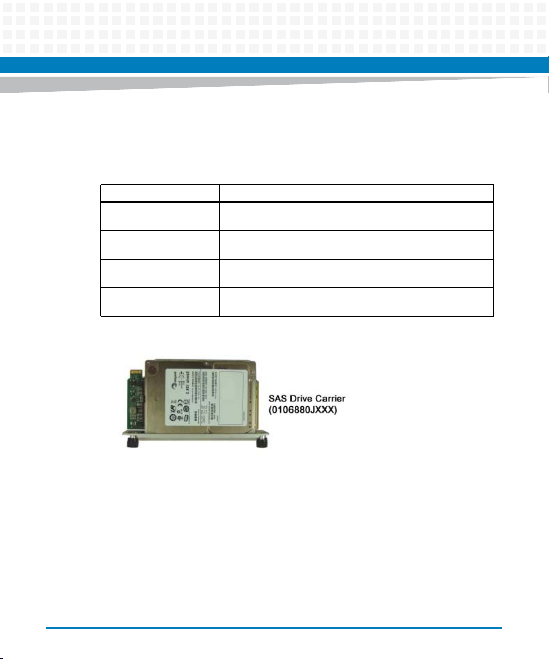
Figure 1-3 SAS Drive Carrier (0106880JXXX) . . . . . . . . . . . . . . . . . . . . . . . . . . . . . . . . . . . . . . . . . 20
Figure 1-4 RTM-ATCA-736X-DD Top View (with disks installed) . . . . . . . . . . . . . . . . . . . . . . . . . 21
Figure 1-5 RTM-ATCA-736X-DD Diagram Showing Identification Label Locations . . . . . . . . . 22
Figure 1-6 Declaration of Conformity . . . . . . . . . . . . . . . . . . . . . . . . . . . . . . . . . . . . . . . . . . . . . . . . 23
Figure 2-1 Injector / Ejector Latch and Locking Screw . . . . . . . . . . . . . . . . . . . . . . . . . . . . . . . . . . 29
Figure 2-2 Drive Carrier Assembly (0106880JXXX) . . . . . . . . . . . . . . . . . . . . . . . . . . . . . . . . . . . . 32
Figure 2-3 Drive Carrier Assembly (DCA) Orientation for Installation . . . . . . . . . . . . . . . . . . . . 35
Figure 3-1 SAS BIOS Start Menu . . . . . . . . . . . . . . . . . . . . . . . . . . . . . . . . . . . . . . . . . . . . . . . . . . . . 39
Figure 3-2 SAS BIOS Adapter Properties, RTM Status and Configuration . . . . . . . . . . . . . . . . . . 40
Figure 3-3 SAS BIOS RAID Level Configuration Menu . . . . . . . . . . . . . . . . . . . . . . . . . . . . . . . . . . 41
Figure 3-4 SAS BIOS, Create New RAID Array . . . . . . . . . . . . . . . . . . . . . . . . . . . . . . . . . . . . . . . . . 43
Figure 4-1 RTM-ATCA-736X-DD Rear Transition Module Connectors . . . . . . . . . . . . . . . . . . . . 48
Figure 4-2 10/100/1000 Mb Management Port Pin Location Diagram . . . . . . . . . . . . . . . . . . . 49
Figure 4-3 Zone 3, Connector Port Pin Location Diagram . . . . . . . . . . . . . . . . . . . . . . . . . . . . . . 51
Figure 5-1 Locations of Disk Eject Jumper and Disk Eject Buttons . . . . . . . . . . . . . . . . . . . . . . . . 65
Figure 5-2 Disk FRU State Diagram, Slave Mode (Normal) . . . . . . . . . . . . . . . . . . . . . . . . . . . . . . 67
Figure 5-3 Disk FRU State Diagram, Stand-alone Mode . . . . . . . . . . . . . . . . . . . . . . . . . . . . . . . . 69
RTM-ATCA-736X-DD Installation and Use (6806800L82C)
9
Page 10

List of Figures
10
RTM-ATCA-736X-DD Installation and Use (6806800L82C)
Page 11

About this Manual
Overview of Contents
This manual supports RTM-ATCA-736X-DD, Rear Transition Module (RTM) with two 1000BaseT Ethernet Ports.
This manual is divided into the following chapters and appendices:
Introduction provides an RTM-ATCA-736X-DD overview.
Installation contains the procedures for installing and removing the RTM-ATCA-736X-DD.
SAS RAID Details provides detailed information on the RTM-ATCA-736X-DD SAS RAID
capabilities.
Mechanical and Connector Information provides mechanical, electrical, environmental, and
other relevant information.
IPMI Functions List provides the details for the function list of the Intelligent Platform
Management Interface.
MMC Firmware Upgrade Procedure provides instructions for upgrading the IPMC (Intelligent
Platform Management Controller) firmware.
Abbreviations
This document uses the following abbreviations:
Abbreviation Definition
AMC Advanced Mezzanine Card
ARP Address Resolution Protocol
RTM-ATCA-736X-DD Installation and Use (6806800L82C)
11
Page 12

About this Manual
Conventions
The following table describes the conventions used throughout this manual.
Notation Description
0x00000000 Typical notation for hexadecimal numbers (digits are
0b0000 Same for binary numbers (digits are 0 and 1)
bold Used to emphasize a word
Screen Used for on-screen output and code related elements
Courier + Bold Used to characterize user input and to separate it
Reference Used for references and for table and figure
About this Manual
0 through F), for example used for addresses and
offsets
or commands in body text
from system output
descriptions
12
File > Exit Notation for selecting a submenu
<text> Notation for variables and keys
[text] Notation for software buttons to click on the screen
and parameter description
... Repeated item for example node 1, node 2, ..., node
12
.
.
.
.. Ranges, for example: 0..4 means one of the integers
| Logical OR
Omission of information from example/command
that is not necessary at the time being
0,1,2,3, and 4 (used in registers)
RTM-ATCA-736X-DD Installation and Use (6806800L82C)
Page 13

Notation Description
Indicates a hazardous situation which, if not avoided,
could result in death or serious injury
Indicates a hazardous situation which, if not avoided,
may result in minor or moderate injury
Indicates a property damage message
No danger encountered. Pay attention to important
information.
About this Manual
Summary of Changes
This manual has been revised and replaces all prior editions.
Part Number Publication Date Description
6806800L82A April 2011 General access release
6806800L82B May 2012 Updated SAS Drive Carrier Assembly Installation on
6806800L82C June 2014 Re-branded to Artesyn.
RTM-ATCA-736X-DD Installation and Use (6806800L82C)
page 32.
13
Page 14

About this Manual
About this Manual
14
RTM-ATCA-736X-DD Installation and Use (6806800L82C)
Page 15

Introduction
1.1 Overview
The RTM-ATCA-736X-DD is a rear transition module (RTM) designed specifically to work with
the Artesyn ATCA-736x processor blade family. The RTM features a two-port 1 Gb Ethernet
controller, a four-port SAS controller and two removable disk cards called SAS Drive Carriers.
The disk cards each hold one 2.5" disk, and fit wholly within the RTM thermal envelope to
provide an environment for proper disk cooling.
Functionally, the RTM-ATCA-736X-DD utilizes two PCI Express buses to connect with the
Ethernet and SAS controllers. The Ethernet controller provides two 1000Base-T Ethernet
connections using RJ45 copper media jacks on the RTM back panel. These ports are compatible
with commodity off-the-shelf, non-proprietary CAT-5E or similar cables.
The SAS controller provides four SAS/SATA ports that each operates at 3 Gb/s. Two SAS ports
route to the removable disks, and two SAS ports route back to the Zone 3 connector for
additional storage expansion. For example, the front blade can add more storage by routing
these ports to disks or to a SAS expander.
Chapter 1
Finally, the RTM-ATCA-736X-DD includes numerous indicator LEDs and a modular
management controller (MMC) with a hot swap notification mechanism to coordinate disk
servicing the front blade OS. The MMC also performs intelligent monitoring and management
tasks and conforms to the PICMG 3.0 and AMC.0 R2 specification.
1.2 Advanced RTM Features
The RTM-ATCA-736X-DD is an 8U (355.6 mm x 80mm) single slot Rear Transition Module that
includes the following interfaces and features:
Intel 82580, Dual 1Gb Ethernet controller (PCI Express Gen 2.0)
Two Ethernet 1000Base-T ports (RJ45)
LSI SAS1064E, Quad 3 Gb SAS controller (PCI Express Gen 1.0a)
Two removable SAS Drive Carriers (0106880J0XX)
RAID 0,1, and 1E capability, with boot
SAS Expander support, up to 122 disks
Handle Ejector switch for hot swap
One recessed push button switch for front blade reset
RTM-ATCA-736X-DD Installation and Use (6806800L82C)
15
Page 16
Introduction
Two recessed push button switches for disk FRU eject request
Temperature and voltage sensors
OOS, health, alarm, and hot swap LEDs
On-board MMC controller for management activities (IPMI)
1.3 I/O PICMG Standards Compliance
The RTM-ATCA-736X-DD is fully compliant with the following PCI Industrial Computer
Manufacturers Group (PICMG) specifications:
PICMG 3.0 Rev 3.0
PICMG AMC.0 Rev2.0 compliance
IPMI v1.5 Intelligent Platform Management Interface Specification
PCI Express 2.0 and 1.0a specifications
1.4 I/O Interfaces
The RTM-ATCA-736X-DD mounts to the ATCA carrier blades using zone-3 connectors,
conforming to PICMG 3.0 ATCA specification revision 3. Internally, the RTM-ATCA-736X-DD
connects zone-3 and the RTM faceplate as follows:
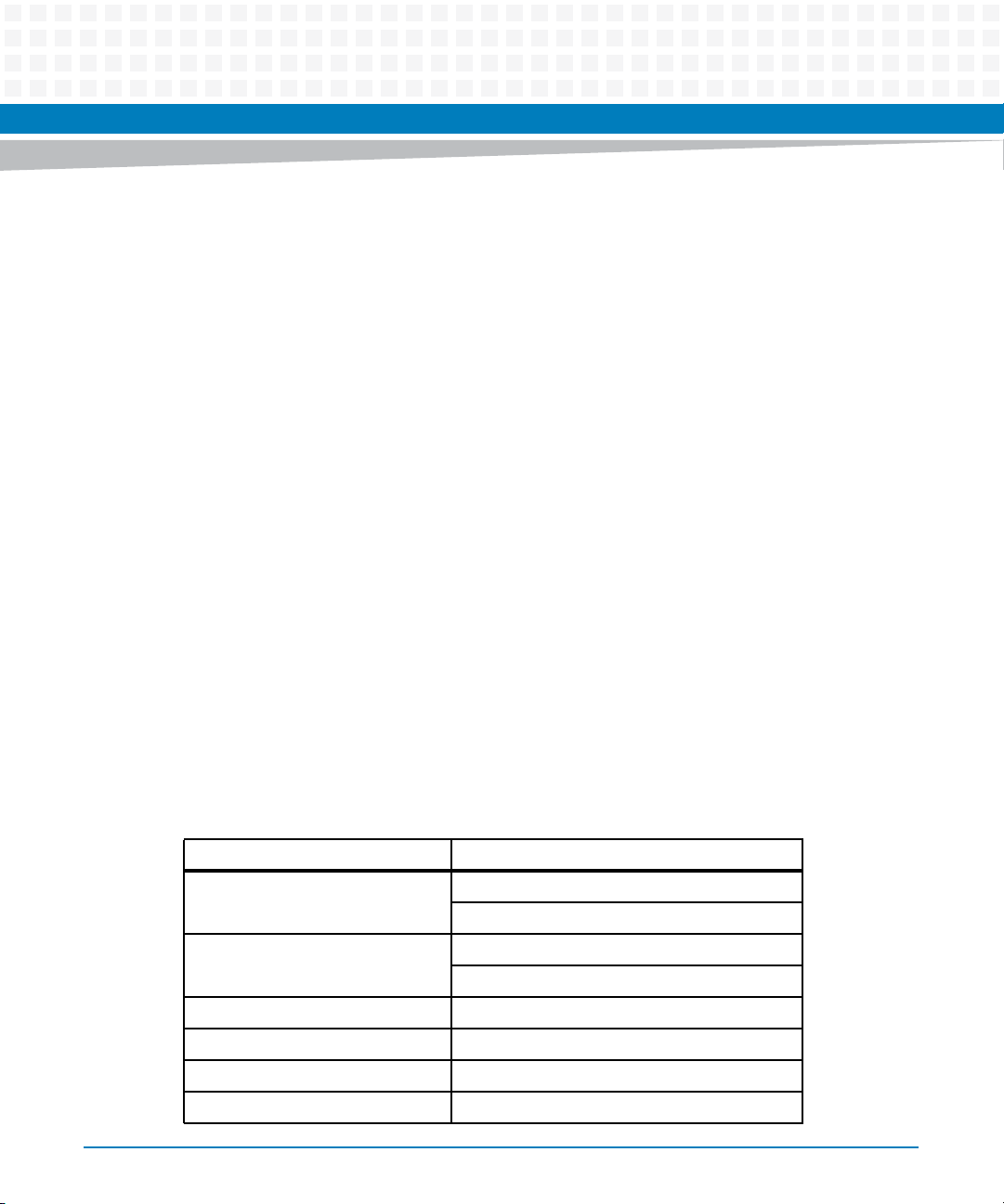
Table 1-1 I/O Ports Available On RTM Faceplate
RTM Zone-3 Electrical Signaling RTM Faceplate
PCIe v1.0, x4 bus #1 Port 1 RJ45 1000Base-T
PCIe v1.0, x8 bus #2 SAS disk field replaceable assembly #1
DCA_SAS, x2 Routes to secondary ports of each SAS drive
LSI_SAS, x2 NA (Routes to LSI Controller)
IPMI - to MMC device on RTM NA
Power NA
16
Port 2 RJ45 1000Base-T
SAS disk field replaceable assembly #2
RTM-ATCA-736X-DD Installation and Use (6806800L82C)
Page 17
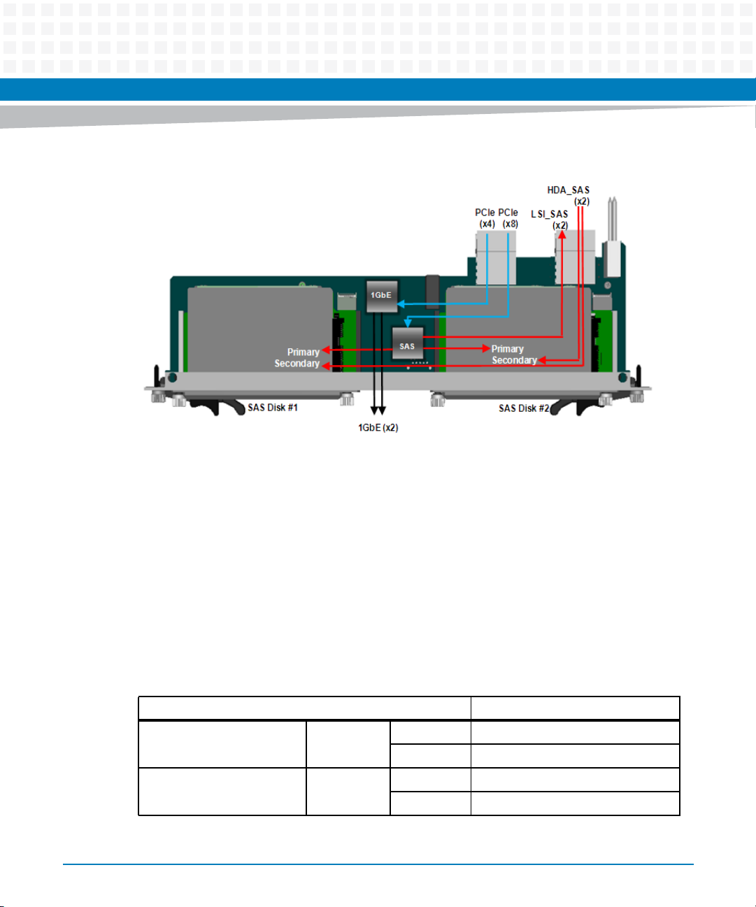
Figure 1-1 RTM-ATCA-736X-DD Functional Interconnect Diagram
Introduction
1.4.1 Ports 1-2, Ethernet 1000Base-T (RJ-45)
Each of these ports route to an Intel® 82580DB Ethernet controller accessed by the front blade
using PCI express signaling. These ports employ an RJ-45 connector with integrated LED for
link (green) and activity (amber). Each port auto negotiates to 10/100/1000BASE-T.
1.5 LEDs
The following LEDs are located on the panel of the RTM-ATCA-736X-DD.
Table 1-2 LEDs On RTM Faceplate
LED RTM Faceplate
Ethernet Activity Amber On LAN management activity LED
Off No activity
Ethernet Link Green On LAN management LINK LED
Off No link
RTM-ATCA-736X-DD Installation and Use (6806800L82C)
17
Page 18
Introduction
Table 1-2 LEDs On RTM Faceplate (continued)
LED RTM Faceplate
Hard Disk Status #1 and #2 None Off SAS Drive Carrier not installed
Hot Swap (HS) Blue On Management power available to the
Green Off Disk in service
Green Blink Disk I/O on SAS port A
Amber Blink Preparing for removal
Amber On Ready/Safe for removal
module and the module can safely
be extracted
Off The module is operational and is
unsafe for extraction
Long Blink Delay before module is activated
Short Blink Delay before module is de-activated
Fault or “Out of Service”
(OOS)
In Service (IS) Green On 12V payload power is being supplied
Attention (ATN) Amber On/Off This LED is controlled by higher layer
Amber/Red On Module fault set by shelf manager or
12V payload power not detected.
Off No module fault 12V payload power
is being supplied to board
to board
Off 12V payload power is not detected
Amber/ Red Off This LED is multicolored
(red/green/yellow) and is programmable by IPMC.
software, such as middle ware or
applications.
18
RTM-ATCA-736X-DD Installation and Use (6806800L82C)
Page 19
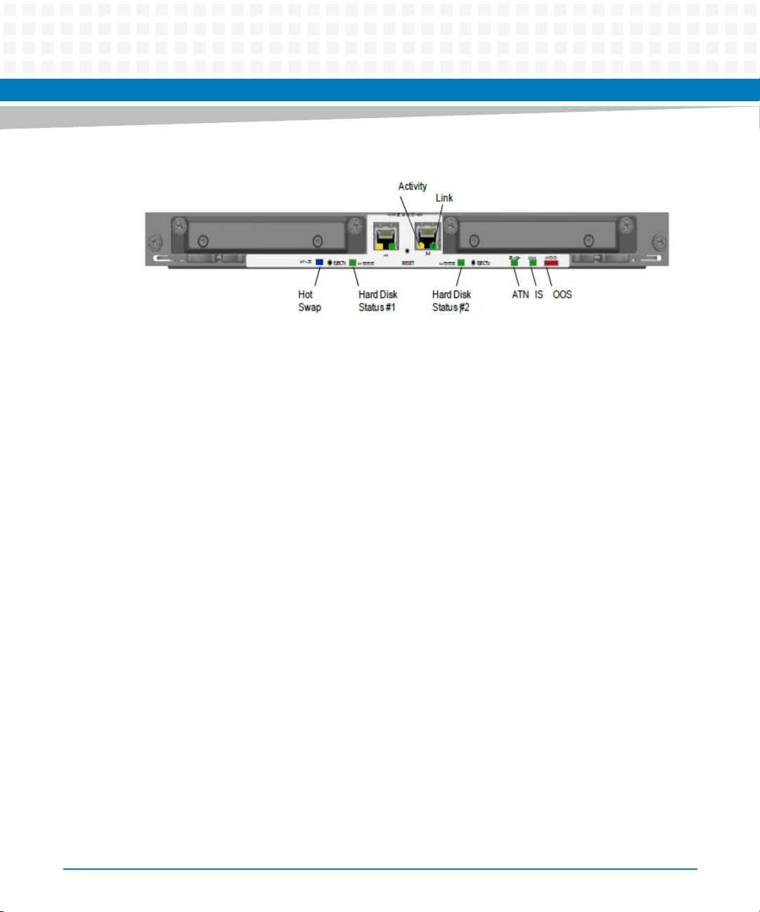
Figure 1-2 RTM-ATCA-736X-DD Back Panel LEDs
1.6 Disk "Request Eject" Button
The RTM-ATCA-736X-DD includes a pair of recessed eject buttons that is marked on the panel
near port 1 (Figure 1-2). Using a thin pointed object, such as a paper clip, a user can depress the
eject button. This action will send a message to the front blade requesting the disk ejection
reset. If granted, the corresponding hard disk status light will turn amber.
Introduction
1.7 Reset Button
The RTM-ATCA-736X-DD includes a recessed reset button that is located between the two
Ethernet ports (see Figure 1-2). Using a thin pointed object, such as a paper clip, a user can
depress the reset button. This action will send a message to the front blade requesting a
payload reset. If granted, the host blade and all peripherals will experience a warm reset.
1.8 Software Support
Except for the drivers for the 82580 Ethernet controller (driver distributed by Intel) and for the
SAS1064E controller (driver distributed by LSI) , RTM-ATCA-736X-DD requires no other special
software to operate. When shipped from the factory, the expander is un-zoned and configured
for table routing.
RTM-ATCA-736X-DD Installation and Use (6806800L82C)
19
Page 20
Introduction
1.9 Products Supported by this Manual
The information in this manual applies to the following Artesyn products:
Table 1-3 Available Board Variants
Marketing Number Description
RTM-ATCA-736X-DD-300 RTM for the ATCA-736X product series, 2X GBE, 2X 147GB SAS HDD
included (ROHS 6/6)
RTM-ATCA-736X-DD-600 RTM for the ATCA-736X product series, 2X GBE, 2X 300GB SAS HDD
included (ROHS 6/6)
RTM-ATCA-736X-1K2 RTM for the ATCA-736X Pproduct series, 2X GBE, 2X 600GB SAS HDD
included (ROHS 6/6)
RTM-ATCA-736X-DD RTM for the ATCA-736X product series, 2X GBE, 2X HDD carrier kits,
no HDD included (ROHS 6/6)
Figure 1-3 SAS Drive Carrier (0106880JXXX)
20
RTM-ATCA-736X-DD Installation and Use (6806800L82C)
Page 21
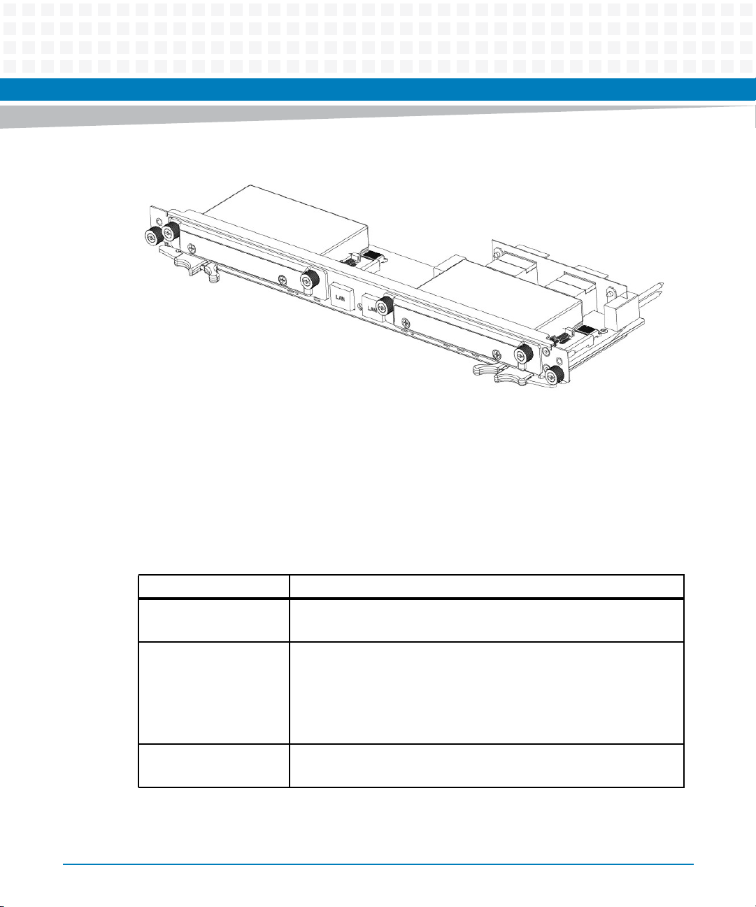
Figure 1-4 RTM-ATCA-736X-DD Top View (with disks installed)
1.10 Identification Labels
Introduction
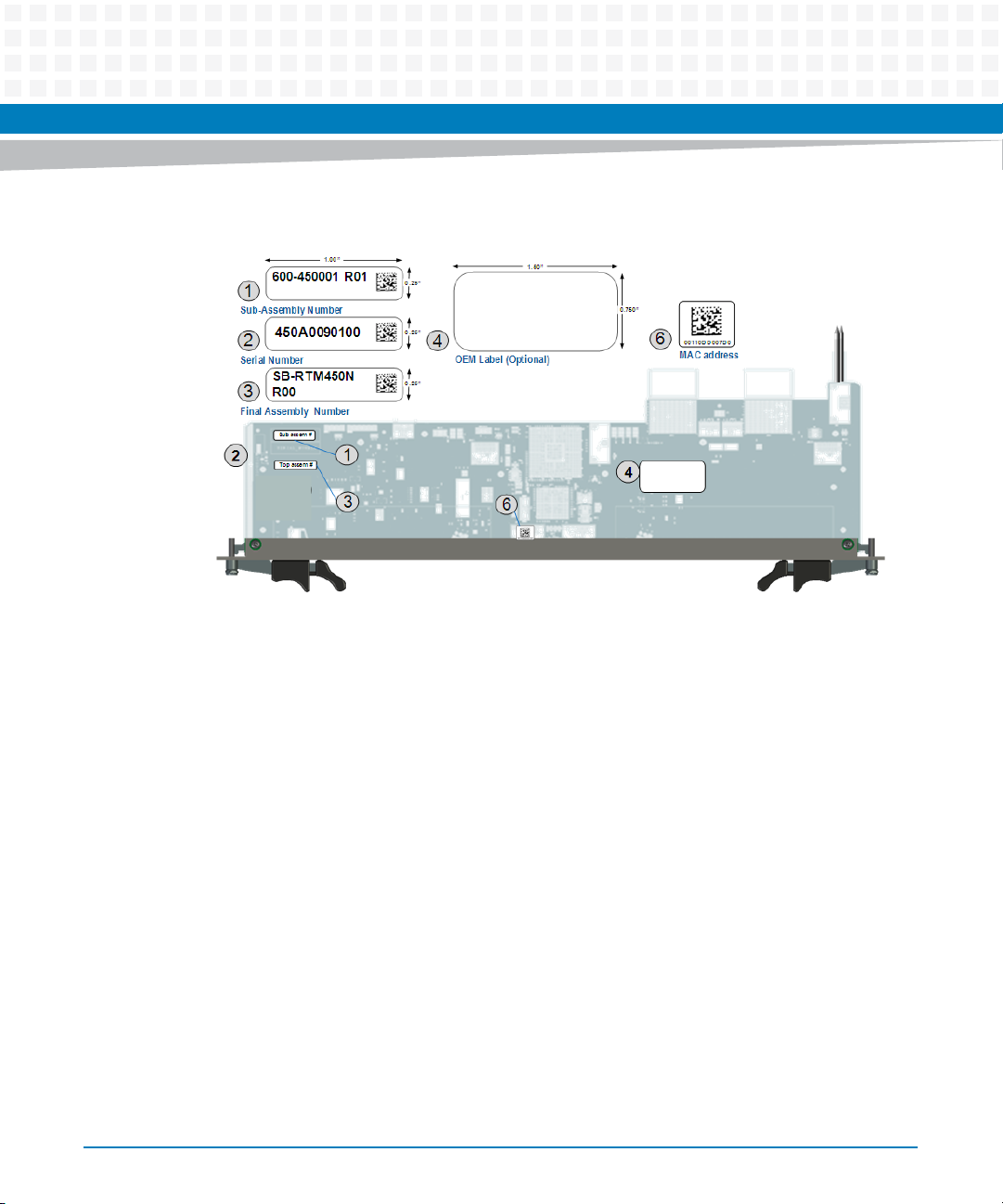
At manufacturing time, several labels are affixed to the RTM-ATCA-736X-DD as shown below.
For proper identification of the RTM module, use these barcode labels to accurately determine
the module identity. The barcode labels provide the following information:
Table 1-4 RTM-ATCA-736X-DD Identification Labels
Label Description
Label 1: Artesyn
Sub-Assembly P/N
Label 2: Artesyn
Serial number (S/N)
Label 3: Final Assembly
P/N
RTM-ATCA-736X-DD Installation and Use (6806800L82C)
P/N = Sub-Assembly Part Number
Rev = Assembly Revision (Refer to Bill Of Material)
S/N Format :AAA = Assembly Number (440)
L =Location of manufacturer (S)
Y = Calendar year of manufacturer ( 2010=0, 2011=1)
MM = Calendar month of manufacturer (March = 03)
SSSS = Sequence number (reset each month) (1234)
P/N = Final Assembly Part Number
Rev = Assembly Revision
21
Page 22
Introduction
Figure 1-5 RTM-ATCA-736X-DD Diagram Showing Identification Label Locations
22
RTM-ATCA-736X-DD Installation and Use (6806800L82C)
Page 23
Introduction
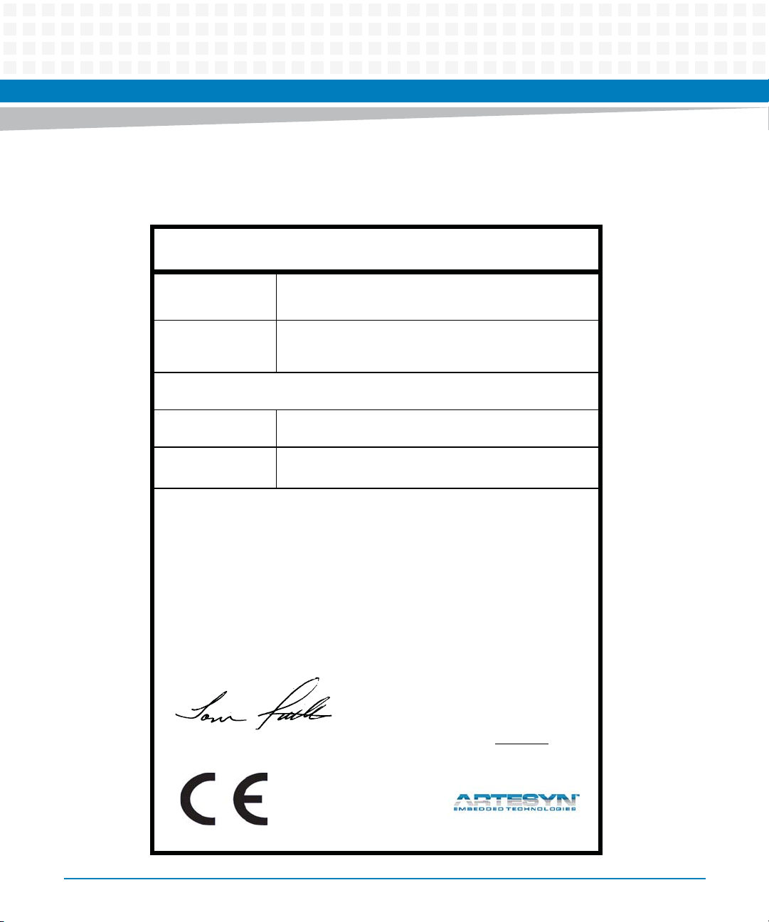
The following figure contains the Declaration of Conformity for RTM-ATCA-736x-DD series.
Figure 1-6 Declaration of Conformity
E
C Declaration of Conformity
According to EN 17050-1:2004
Manufacturer’s Name:
Manufacturer’s Address:
Declares that the following product, in accordance with the requirements of 2004/108/EC, 2006/95/EC,
2011/65/EU and their amending directives,
Product:
Model Name/Number:
has been designed and manufactured to the following specifications:
EN55022:2010
EN55024:2010
ETSI EN 300 386 V1.5.1 (2010-10)
IEC 60950-1:2005 (2nd Edition), EN60950-1:2006+A11:2009
2011/65/EU RoHS Directive
As manufacturer we hereby declare that the product named above has been designed to comply with the relevant sections of the above referenced specifications. This product complies with the essential health and safety
requirements of the above specified directives. We have an internal production control system that ensures
compliance between the manufactured products and the technical documentation.
Artesyn Embedded Technologies
Embedded Computing
Zhongshan General Carton Box Factory Co. Ltd. No 62, Qi
Guan Road West, Shiqi District, 528400 Zhongshan City
Guangdong, PRC
Rear Transition Module for the ATCA-7365, -737X-, 747X– Product
Series
RTM-ATCA-736X-10G, RTM-ATCA-736X-10G-SP,
RTM-ATCA-737X-10G, RTM-ATCA-736X-DD-1K2,
RTM-ATCA-736X-DD-300, RTM-ATCA-736X-DD-300
___________________________________________________ ___
Tom Tuttle, Manager, Product Testing Services Date (MM/DD/YYYY)
RTM-ATCA-736X-DD Installation and Use (6806800L82C)
06/10/2014
______
23
Page 24

Introduction
24
RTM-ATCA-736X-DD Installation and Use (6806800L82C)
Page 25

Chapter 2
Installation
2.1 Overview
This chapter contains the procedures for installing and removing the RTM-ATCA-736X-DD
RTM.
2.2 Installation and Removal of the Rear Transition Module
The RTM-ATC A-736X-DD can be installed into an ATCA shelf (chassis) with a midplane made for
front and rear board installations. The module must be installed in the slot directly behind the
host ATCA node board. These back-to-back slots have common pins to enable passing of
signals using the Zone-3 connector complex.
2.3 Important Information about Your Chassis
Before installing the rear transition module, verify the module's part number to ensure that the
correct rear transition module is being installed into the system. For information on identifying
the rear transition module, see Products Supported by this Manual, on page 20.
2.3.1 Safety Statement
The RTM-ATCA-736X-DD is designed to comply with IEC60950-1, and is intended to be used
with similarly tested AdvancedTCA products that have a user's guide detailing user installation
of module accessories.
2.3.2 Observe Maximum Module Current Requirements
There are several manufacturing options for the RTM. Be sure to validate that the host chassis
can supply the RTM slot with these maximum current requirements.
Table 2-1 Maximum RTM Module Current Requirements
RTM-ATCA-736X-DD
Module Current
+12 V (spin up < 100 sec) 0.55 A (6.6 W) 1.9 A (22.9 W) (staggered spin-up)
(No Disk) RTM-ATCA-736X-DD (Two SAS Disk)
RTM-ATCA-736X-DD Installation and Use (6806800L82C)
25
Page 26

Installation
Table 2-1 Maximum RTM Module Current Requirements (continued)
RTM-ATCA-736X-DD
Module Current
+12 V normal operating 0.55 A (6.6 W) 1.63 A (19.6 W)
OFF STATE LESS THAN 0.4 W LESS THAN 0.4 W
(No Disk) RTM-ATCA-736X-DD (Two SAS Disk)
2.4 Before You Install Or Remove the RTM
Boards may be damaged if improperly installed or handled. Please read and follow the
guidelines in this section to protect your equipment.
2.4.1 Observe ESD Precautions
Artesyn strongly recommends that you use an antistatic wrist strap and a conductive foam pad
when installing or upgrading a system. Electronic components, such as disk drives, computer
boards, and memory modules, can be extremely sensitive to electrostatic discharge (ESD).
After removing the component from its protective wrapper or from the system, place the
component flat on a grounded, static-free sur face (and, in the case of a board, component side
up). Do not slide the component over any surface.
If an ESD station is not available, you can avoid damage resulting from ESD by wearing an
antistatic wrist strap (available at electronics stores) that is attached to an active electrical
ground. Note that a system chassis may not be grounded if it is unplugged.
2.4.2 Watch for Bent Pins or Other Damage
Bent pins or loose components can cause damage to the board, the backplane, or other system
components. Carefully inspect your board and the backplane for both pin and component
integrity before installation. Bent pins caused by improper installation or by boards with
damaged connectors could void the warranty for the backplane or boards.
If a system contains one or more damaged pins, power off the system and contact your local
sales representative to schedule delivery of a replacement chassis assembly.
26
RTM-ATCA-736X-DD Installation and Use (6806800L82C)
Page 27

Installation
2.5 Use Caution When Installing or Removing RTM
When first installing boards in an empty chassis or onto a carrier card, we recommend that
you start at the left of the card cage and work to the right.
When inserting or removing a board in a slot adjacent to other boards, use extra caution to
avoid damage to the pins and components located on the primary or secondary sides of the
boards.
2.5.1 Preserve EMI Compliance
To preserve compliance with applicable standards and regulations for electromagnetic
interference (EMI), during operation, all front and rear openings on the chassis or board
faceplates must be filled with an appropriate card or covered with a filler panel. If the EMI
barrier is open, devices may cause or be susceptible to excessive interference.
2.5.2 Understand Hot Swap
Your RTM is electrically designed for hot swap within a fully powered chassis. To facilitate hot
swap, there is a blue LED on the rear faceplate. This LED is under software control.
If your system is using software that provides full hot swap capabilities, the software will
illuminate the blue hot swap LED on the rear faceplate when software has stopped and it is safe
to remove the advanced rear transition module.
If your system does not have hot swap-aware software running, the behavior of the blue LED is
not determined. In this case, you may need to manually shut down applications or operating
systems running on the board prior to board removal, even if the blue LED is lit.
RTM-ATCA-736X-DD Installation and Use (6806800L82C)
27
Page 28

Installation
Powering down or removing a board before the operating system or other software running on
the board has been properly shut down may cause corruption of data or file systems.
Depending on the type of front blade the RTM is connected to, hot swapping the RTM will
cause the front board to power down its payload. Please consult Artesyn Embedded
Technologies documentation of the relevant front board for further details about RTM hot
swap.
2.6 Verify Slot Usage
Prevent possible damage to module components by verifying the proper slot usage for your
configuration.
2.7 Installing the Advanced Rear Transition Module
28
This section describes a recommended procedure for installing the RTM module in a chassis.
Before you install your module, please read all cautions, warnings, and instructions presented
in this section.
Handling modules and peripherals can result in static damage. Use a grounded wrist strap,
static-dissipating work surface, and antistatic containers when handling and storing
components.
Insert the board by holding the module handles. Do not exert unnecessary pressure on the
faceplate.
Hot swap compliant modules may be installed while the system is powered on. If a module is
not hot swap compliant, you should remove power to the slot or system before installing the
module. Please consult Artesyn Embedded Technologies documentation of the relevant front
board for further details about RTM hot swap.
Installation Process
1. Verify that you have taken the necessary antistatic precautions.
2. Go to the back of the system and choose an appropriate slot for the rear transition module.
RTM-ATCA-736X-DD Installation and Use (6806800L82C)
Page 29

Installation
Rear transition modules must be installed in-line behind the accompanying node board. For
example, if the accompanying node board is going to be installed in slot 3, its rear transition
module must be installed at the back of the system in slot 3.
3. Remove the slot filler panel from the selected node board slot, if necessary.
4. Prepare the module by loosening the locking screws and opening the injector/ejector latch
at the top of the module as shown in the figure below.
Figure 2-1 Injector / Ejector Latch and Locking Screw
5. Carefully align the edges of the module with the guides in the appropriate slot.
Look into the enclosure to verify correct alignment of the rails in the guides. Align the edges
of the module with the card cage rail guides in the appropriate slot.
RTM-ATCA-736X-DD Installation and Use (6806800L82C)
29
Page 30

Installation
6. Keeping the module aligned with the guides, apply equal and steady pressure and slide the
module in until the injector/ejector mechanism engages with the retention bars.
7. Position your thumbs at the top and bottom of the RTM; simultaneously push in the module
and rotate the injector/ejector mechanisms inward to its closed position to seat and secure
the RTM. DO NOT FORCE THE BOARD INTO THE SLOT.
8. Tighten the two module retention screws to secure the module into the shelf.
9. Power on the system, if necessary. Refer to your system manual for instructions on correctly
powering on the system. Once power is applied to the chassis, the internal MMC controller
runs a self-test that runs for approximately 10 seconds. Upon a successful power up selftest, the blue hot swap LED will blink and then turn off, indicating that the module has been
placed in operation.
2.8 Removing the Advanced Rear Transition Module
The RTM-ATCA-736X-DD RTM is hot-swappable and can be removed from the chassis without
powering down its associated node board if supported by the front board. Please consult
Artesyn Embedded Technologiesdocumentation of the relevant front board for further details
about RTM hot swap. This section describes a recommended procedure for removing a board
module from a chassis.
Before you remove your module, please read all cautions, warnings, and instructions presented
in this section. Hot swap compliant modules may be removed while the system is powered on.
If the chassis is not hot swap compliant, you should remove power to the slot or system before
removing the module.
Removing an RTM
1. Loosen the locking screws on the rear transition module.
2. Rotate the top ejector handle to half way (HW) position. Do not remove the module
immediately.
3. If your host module is running a hot swap-aware software, the action of rotating the ejector
lever will start the shutdown process on the board. The software will slowly blink the blue
hot swap LED indicating the module is in the process of being deactivated.
4. Once the module has been deactivated, the blue LED will illuminate steadily. Once this is
done, you can extract the module by pulling on the module handle.
30
RTM-ATCA-736X-DD Installation and Use (6806800L82C)
Page 31

Note: Powering down or removing a board before the operating system or other software
running on the board has been properly shut down may cause corruption of data or file
systems.
5. If your board or system is not running hot swap-aware software, the blue LED may
illuminate without regard to software processes still running on the board. Be sure to
manually shut down applications or operating systems running on the board prior to board
removal.
6. Carefully pull the module from the chassis.
7. If the card slot is to remain empty, install a filler panel in the slot.
2.9 Verifying the Hardware Installation
This section provides information to verify the installation of the RTM-ATCA-736X-DD module.
Manually inspect the module power LED on the RTM panel. Refer to Figure "RTM-ATCA-736X-
DD Back Panel LEDs" on page 19.
Installation
RTM-ATCA-736X-DD Installation and Use (6806800L82C)
31
Page 32

Installation
2.10 SAS Drive Carrier Assembly Installation
The RTM-ATCA-736X-DD can accommodate two SAS drive carrier assembly. These assemblies
support disk serviceability and hot swap without removing the RTM. This section describes the
recommended procedure for installing the drive carrier assembly.
Figure 2-2 Drive Carrier Assembly (0106880JXXX)
32
RTM-ATCA-736X-DD Installation and Use (6806800L82C)
Page 33

Installation
To install a DCA, follow these steps:
1. Verify that you have taken the necessary antistatic precautions.
2. Place the hard disk insulator on the top of the SAS-PCB assembly.
3. Align the insulator holes with the holes on the board.
4. Place the hard disk on the top of the insulator, such that it is aligned with the board SATA
connector.
5. Slide the hard disk into the SATA connector.
6. Flip assembly on its back and align the SAS-PCB holes with the insulator and hard
disk holes.
7. Attach the drive support bracket to the side of the hard disk.
8. Tighten the four flat head screws to secure the drive support bracket to the hard
disk.
9. Tighten the two pen head screws to fix the hard disk, insulator, and SAS-PCB
together.
10.Assemble the front panel bezel to the disk drive assembly using two flat head
screws.
2.11 SAS Drive Carrier Assembly Removal (Eject)
The RTM-ATCA-736X-DD can accommodate two SAS Drive Carrier Assemblies (DCA). These
assemblies support disk serviceability and hot swap without removing the RTM. This section
describes the recommended procedure for removing the hard disk assembly.
RTM-ATCA-736X-DD Installation and Use (6806800L82C)
33
Page 34

Installation
To remove a DCA, follow these steps:
1. Locate the hole marked "EJECT" corresponding to DCA #1 or #2. Insert a paperclip about 0.5
inches to engage a spring-loaded plastic micro switch.
Note: Removing a DCA without properly preparing the operating system or other software
using the disk, may cause corruption of data or file systems.
2. The corresponding DCA status LED will blink in amber color for approximately five seconds.
The blink indicates the DCA is being de-activated.
3. Once the module has been de-activated, the DCA status LED illuminates steady amber.
4. Loosen the locking thumbscrews on the DCA. Carefully pull the module from the chassis.
34
RTM-ATCA-736X-DD Installation and Use (6806800L82C)
Page 35

5. If the card slot is to remain empty, install a filler panel in the slot.
Figure 2-3 Drive Carrier Assembly (DCA) Orientation for Installation
Installation
RTM-ATCA-736X-DD Installation and Use (6806800L82C)
35
Page 36

Installation
36
RTM-ATCA-736X-DD Installation and Use (6806800L82C)
Page 37

SAS RAID Details
3.1 Overview
This chapter provides detailed information on the RTM-ATCA-736X-DD SAS RAID capabilities.
3.2 Hard Disk Drive Controller
The RTM-ATCA-736X-DD includes an LSI SAS 1064e hard disk drive controller with the
following features:
Four-lane PCIe interface (full duplex 2.5 Gb/sec)
Four SAS ports (3.0 Gb/sec) with 1 port routed to each hard disk drive slot.
3.3 SAS Boot BIOS Features
Chapter 3
The Boot BIOS for Intel/AMD-based platforms is stored on the flash device located on the
module.
The SAS boot BIOS supports the following features:
Support multiple SAS controllers
Apply global properties stored in flash
Selection and configuration for up to 256 adapters
Automatic INT13 drive mapping for SAS drives
SAS topology discovery, including expander traversal
Apply PHY transceiver properties
RTM-ATCA-736X-DD Installation and Use (6806800L82C)
37
Page 38

SAS RAID Details
3.4 Brief Theory of BIOS Operation
If Boot is enabled, the boot BIOS will scan for SAS hard disks (HD) connected to the RTM.
Discovered disk(s) are enumerated with drive letters and appended to a master list of “devices”
discovered on the host. Upon scan completion, the host will serially inspect the master list of
devices beginning with drive A, and attempt to boot from the first device it finds with a boot
record.
The boot feature is enabled by default on this product.
3.5 Boot BIOS Configuration Utility
The BIOS configuration utility is stored in a flash device located on the RTM module. LSI
Corporation authored the BIOS used on the RTM module. The sections that follow will provide
the user a summary of the BIOS configuration capabilities.
3.5.1 Launching the Boot BIOS Configuration Utility
The boot BIOS allows you to change the default configuration of your RTM module. When the
BIOS loads, the following message appears on your monitor:
Press Ctrl-C to start LSI Configuration Utility...
This message remains on your screen for about five seconds, giving you time to start the utility.
After you press CTRL+C, the message changes to:
Please wait, invoking LSI Configuration Utility...
38
RTM-ATCA-736X-DD Installation and Use (6806800L82C)
Page 39

After a brief pause, your computer monitor displays the main menu of the BIOS Configuration
Utility.
Not all devices detected by the Configuration Utility can be controlled by the BIOS. Devices
such as tape drives and scanners require loading a device driver specific to that peripheral.
The BIOS Configuration Utility allows parameters to be modified for these devices.
3.5.2 BIOS Launch: Main Menu
When the boot BIOS Configuration Utility is launched, the main menu appears. This screen
displays a scrolling list of all the SAS controllers visible in the system, along with PCI Express
identification information. Use the arrow keys to select the RTM module you wish to modify,
and press ENTER to view and modify module properties.
SAS RAID Details
Figure 3-1 SAS BIOS Start Menu
RTM-ATCA-736X-DD Installation and Use (6806800L82C)
39
Page 40

SAS RAID Details
3.5.3 Adapter Properties Menu
This menu provides the top level view of module status and manageable attributes. Using the
arrow keys, move to the menu item you wish to select and press ENTER.
Figure 3-2 SAS BIOS Adapter Properties, RTM Status and Configuration
3.6 RAID Firmware Capability
The RTM-ATCA-736X-DD product includes additional firmware to construct RAID volumes
using a disk on the RTM and a disk externally connected to the RTM. Please consult your host
blade documentation to verify this capability.
40
RTM-ATCA-736X-DD Installation and Use (6806800L82C)
Page 41

3.6.1 BIOS, RAID Properties Menu
This menu allows the user to select the desired RAID level for a volume definition. Using the
arrow keys, move to the menu item you wish to select and press ENTER.
Figure 3-3 SAS BIOS RAID Level Configuration Menu
SAS RAID Details
RTM-ATCA-736X-DD Installation and Use (6806800L82C)
41
Page 42

SAS RAID Details
Menu Text RAID Level Description
None Default. All discovered disks are presented to the host blade
or CPU, with no RAID function.
IS Volume
(Integrated Stripe)
IM Volume
(Integrated Mirror)
IME volume
(Integrated Mirror
Enhanced)
RAID0 Two or more disks are grouped to provide a capacity
aggregation function. The advantage is the multiplicative
performance and capacity effect of four spindles working in
concert to store or retrieve data for the host.
RAID1 Two disks are grouped to provide a mirror function. By
definition, two drives our bounded such that every write to
one drive is mirrored on the second. If a failure occurs with
either drive, the data is still accessible through the surviving
drive.
RAID1E Three or more disks are grouped to provide a mirror function
using an algorithm extension to permit use with many drives.
If a failure occurs with any drive, data is still accessible through
the surviving drives.
3.6.2 BIOS, RAID Create New Array and Global Hot Spare
This menu enables the user to choose the disks that will comprise new RAID volumes or global
hot spares. Using the keyboard arrow keys, highlight the drives in the "RAID DISK" column, and
use the space bar to change to "Yes" or "No", "Yes" if the disk will be a member of the new array
and "No", if otherwise. Alternatively, highlight the drives in the "Hot Spr" (global hot spare)
column, and use the space bar to change to "Yes" or "No", "Yes" if the disk will be a member of
the global hot spare and "No", if otherwise. A maximum of two drives may be designated as a
global hot spare.
42
RTM-ATCA-736X-DD Installation and Use (6806800L82C)
Page 43

SAS RAID Details
In this screen shot example, a total of four drives were detected. Two are marked to become
the IM (RAID1) volume, and a third is designated as a global hot spare for the volume. Press the
"C" key to create the volume.
Figure 3-4 SAS BIOS, Create New RAID Array
RTM-ATCA-736X-DD Installation and Use (6806800L82C)
43
Page 44

SAS RAID Details
44
RTM-ATCA-736X-DD Installation and Use (6806800L82C)
Page 45

Mechanical and Connector Information
4.1 Specifications
This section provides mechanical, electrical, environmental, and other relevant information.
4.1.1 Physical Dimensions
The RTM-ATCA-736X-DD is an 8U (355.6 mm) height board with 80 mm depth for standard
applications. It complies with PICMG 3.0 Revision 3.0 specification. The RTM-ATCA-736X-DD is
keyed to conform to the PICMG 3.0, Keying of ATCA Boards and Backplanes specification.
4.1.2 Weight
The weight of the RTM-ATCA-736X-DD is listed below.
Chapter 4
Table 4-1 RTM-ATCA-736X-DD Weight
Description
RTM Board 570 g 1000 g
RTM board in shipping box 1125 g 1555 g
4.1.3 Power Requirements
There are several manufacturing options for the RTM. Be sure to validate that the host chassis
can supply the RTM slot with these maximum current requirements. See Table "Maximum RTM
Module Current Requirements" on page 25.
RTM-ATCA-736X-DD (No
disks)
RTM-ATCA-736X-DD (Dual disks
installed)
RTM-ATCA-736X-DD Installation and Use (6806800L82C)
45
Page 46

Mechanical and Connector Information
4.1.4 Environmental Specifications and Compliance
The environmental specifications for the RTM-ATCA-736X-DD assembly are presented in the
table below.
Table 4-2 Environmental Specifications for the RTM-ATCA-736X-DD
RTM with rotating SAS Disk Media
Specification
Operating Voltage +12V +/- 5% (payload power) +12V +/- 5% (payload power)
Operating Temperature (normal) +5°C to +40°C +0°C to +49°C
Installed RTM without Disks
Operating Temperature (short term) -5°C to +55°C (Consult disk drive
manufacturer for warranty
implications)
Storage Temperature -40 °C to 70°C -40 °C to 100°C
Operating Temperature Gradient 11°C /H (max) 11°C /H (max)
Storage Temperature Gradient 20°C /H (max) 20°C /H (max)
Shipping Temperature Gradient 20°C /H (max) *1 20°C /H (max)
Operating Humidity 5% to 85% (non condensing) 5% to 90% (non condensing)
Storage Humidity 5% to 90% (non condensing) 5% to 90% (non condensing)
Shipping Humidity 5% to 90% (non condensing) No condensation
Condensation No condensation No condensation
Altitude, operating (relative to sea
level)
Altitude, non-operating (relative to
sea level)
Shock, operating 980 m/s2 (100G) / 1 ms duration 500G / 0.5msec duration
Shock, non-operating 3,920 m/s2 (400G) / 1 ms duration 1000G / 0.5msec duration
Vibration, operating 0.6 mm (5 to 20Hz) / 9.8 m/s2 (1G)
-305 to +3,048 m (-1000 to +10,000
feet)
-305 to +12,192 m (-1000 to
+40,000 feet)
(20 to 300Hz) or less Note: At
random seek write/read and default
on retry setting with log sweep
vibration.
+0°C to 70°C
(-1000 to +40,000 feet)
(-1000 to +40,000 feet)
2.17 GRMS (5-700Hz)
46
RTM-ATCA-736X-DD Installation and Use (6806800L82C)
Page 47

Mechanical and Connector Information
Table 4-2 Environmental Specifications for the RTM-ATCA-736X-DD (continued)
RTM with rotating SAS Disk Media
Specification
Vibration, non-operating 3.1 mm (5 to 20Hz) / 49m/s2 (5G)
RoHS 6 of 6 compliant 6 of 6 compliant
MTBF Not calculated 972,226 hours (@25C)
Installed RTM without Disks
3.13 GRMS (5-800Hz)
(20 to 300Hz) or less. Note: At
power-off state after installation
4.1.5 NEBS Compliance
NEBS certifications are performed by integrator at a system level (chassis, ATCA, shelf
managers, etc.). The RTM module will not preclude the system from passing NEBS.
4.1.6 Electromagnetic Compliance
The board is designed and implemented to minimize electromagnetic emissions,
susceptibility, and the effects of electrostatic discharge.
Table 4-3 EMC Emission Compliance
Standard Description
US: FCC 47 CFR Part 15 Class A FCC Class A emissions requirements (United States)
ICES-003 2004 Class A Class A Interference-causing Equipment standard (Canada)
VCCI V-3/2007.04 Class A Class A ITE emissions requirements (Japan)
Europe Commercial: EN5022:2006 Class A, ITE Class A ITE emissions requirements (EU, Europe)
AS/NZS CISPR 22:2005 Class A, ITE Class A ITE emissions requirements (Australia)
Europe Commercial: EN
55022:1998/A1:2000/A2:2003
Europe Commercial: EN
55024:1998A1:2001/A2:2003
Europe Commercial: EN 61000-4-2,3,4,5,6: 2001 EMC Electrostatic discharge immunity
Immunity for ITE equipment
Immunity for ITE equipment
RTM-ATCA-736X-DD Installation and Use (6806800L82C)
47
Page 48

Mechanical and Connector Information
4.2 Connectors and Pin Assignments
This section provides position and pin-out details of all connectors available on the RTM-ATCA736X-DD.
Table 4-4 Connector Port Identification snd Location
1 Disk FRU # 1 4 Zone 3 connector
2 1000BASE-T Ethernet 5 RTM alignment pin
3 Disk FRU # 2
Figure 4-1 RTM-ATCA-736X-DD Rear Transition Module Connectors
48
RTM-ATCA-736X-DD Installation and Use (6806800L82C)
Page 49

4.2.1 1000Base-T Ethernet Ports
Two Ethernet ports are provided on the rear panel of the RTM using an RJ-45 style shielded
connectors. Each of these ports route to an Intel® 82580 Ethernet controller, and accessed by
the front blade through PCI express signaling. Each port auto negotiates to 10/100/1000BASET.
Table 4-5 10/100/1000 Management Port Connector Pin Assignments
Pin Signal Name Pin Signal Name
1 LAN0_A+ 5 LAN0_C-
2 LAN0_A- 6 LAN0_B-
3 LAN0_B+ 7 LAN0_D+
4 LAN0_C+ 8 LAN0_D-
Mechanical and Connector Information
Figure 4-2 10/100/1000 Mb Management Port Pin Location Diagram
RTM-ATCA-736X-DD Installation and Use (6806800L82C)
49
Page 50

Mechanical and Connector Information
4.2.2 Zone 3 Connectors
The RTM-ATCA-736X-DD routes several I/O signals to the Zone-3 connector complex
consisting of connectors J30 and J32. These connectors enable expansion using rear transition
modules (RTM) whose "J" connectors mirror the "P" connectors located on the carrier module.
All of these connectors utilize a 4-pin per column type available from Tyco electronics (PN#
1469048-1, http://www.tycoelectronics.com).
The connector pin-outs are presented from the point of view of ATCA blade, such that:
"TX" refers to ATCA blade as the signal source, and RTM as the signal receiver.
"RX" refers to ATCA blade as signal receiver, and RTM as the signal source.
50
RTM-ATCA-736X-DD Installation and Use (6806800L82C)
Page 51

Mechanical and Connector Information
Figure 4-3 Zone 3, Connector Port Pin Location Diagram
4.2.2.1 Connector J30, Power Supply for Advanced RTM
The RTM-ATCA-736X-DD draws power from +12 V and the +3.3 V management voltages
through the P30 connector. The RTM will convert the main 12 V payload power into 1.0 V, 1.8
V, 2.5 V and 3.3 V by using DC/DC converters.
RTM-ATCA-736X-DD Installation and Use (6806800L82C)
51
Page 52

Mechanical and Connector Information
4.2.2.2 Connector J30, Storage and Management Infrastructure Pin Assignments
The following table presents the RTM-ATCA-736X-DD J30 connector pin assignments and
descriptions:
Table 4-6 Connector P30, Management infrastructure Pin Assignments
Row Interface A B C D E F G H
1 88_Serial
_RXD
2 SAS LSI_SAS[
3]TX+
3 SAS LSI_SAS[
2]TX+
4 USB USB+ USB- n.c. n.c. SATA[1]TX+SATA[1]TX-SATA[1]RX+SATA[1]RX-
5 n.c. n.c. n.c. n.c. n.c. n.c. n.c. n.c.
6 PCIe-10 3 P10_Rx0+P10_Rx0- P10_Tx0+P10_Tx0- P10_Rx1+P10_Rx1- P10_Tx1+P10_Tx1-
7 PCIe-10 3 P10_Rx2+P10_Rx2- P10_Tx2+P10_Tx2- P10_Rx3+P10_Rx3- P10_Tx3+P10_Tx3-
8 Test P10_Clk1
00+
9 IPMB IPMB_SCLIPMB_SDAV3P3_M
10 POWER VP12 VP12 n.c. n.c. n.c. ENABLE_NI2C_CLK I2C_DAT
88_Serial
_TXD
LSI_SAS[
3]TX-
LSI_SAS[
2]TX-
P10_Clk1
00-
TDO TDI n.c. n.c. PS1_N POWERGOOD
LSI_SAS[
3]RX+
LSI_SAS[
2]RX+
88_PCIE_
RST
GMT
LSI_SAS[
3]RX-
LSI_SAS[
2]RX-
JTAG_TRSTJTAG_TCKJTAG_TMS88_SHIFT
n.c. reserved 88_PS0_N88_RST_
DCA2_SA
S_TX+
DCA1_SA
S_TX+
DCA2_SA
S_TX-
DCA1_SA
S_TX-
DCA2_SA
S_RX+
DCA1_SA
S_RX+
_CLK
KEY_N
DCA2_SAS_RX-
DCA1_SAS_RX-
88_LATCH_CLK
88_RST_OUT_N
Table 4-7 Connector J30, Management Infrastructure Signal Descriptions
88_Serial_RXD O LVTTL Serial line receives data to the front board CPU.
88_Serial_TXD I LVTTL Serial line transmits data from the front board CPU.
V3P3_MGMT +3.3V Management Power is used exclusively for management power.
PS1_N O RTM Presence signal. The front board reads this active low signal to determine
if an RTM is present and fully inserted.
52
RTM-ATCA-736X-DD Installation and Use (6806800L82C)
Page 53

Mechanical and Connector Information
Table 4-7 Connector J30, Management Infrastructure Signal Descriptions (continued)
POWERGOOD O Open Drain. When low indicates to RTM that it is fully inserted and that MMC
can start execution. Logic high shall keep MMC in reset state. This signal shall
have a pull-up resistor.
LSI_SAS[ ] I/O LVDS. These transceiver pairs connect to the LSI SAS controller, port2 and
port3. Some front blades route these ports to the Zone2 update channel
where additional disks may reside.
DCA1_SAS[] I/O LVDS. These transceiver pairs route to the secondary SAS por t of the hard drive
located on DCA (drive carrier assembly) #1
DCA2_SAS[] i/O LVDS. These transceiver pairs route to the secondary SAS port of the hard drive
located on DCA (drive carrier assembly) #2
SATA[ ] I/O (Unused) LVDS. These transceiver pairs are driven by a storage controller on
the host blade.
USB I/O (Unused) USB bidirectional, differential data pin pair
TDO, TDI Test Data In/Out signals as defined in JTAG. The RTM provides a bypass circuit
to propagate this signal and complete the test data chain (that is, TDI connects
to TDO)
P10_Rx, P10_Tx,
P10_Clk100+
88_PCIE_RST PCIE Reset driven by host blade.
IPMB_SCL,
IPMB_SDA
VP12 12V Payload Power, enabled after successful E-keying, as outlined in the AMC.0
(Unused) LVDS. Port #10 PCI express differential signal pairs for transmit
receive and 100MHz reference Clock
IPMI/I2C serial-bus clock and data signals, as defined in AMC.0 specification.
specification.
4.2.2.3 Connector J32, PCI-Express and Test Infrastructure Pin Assignments
The RTM-ATCA-736X-DD , J31 connector pin assignments and descriptions appear below.
RTM-ATCA-736X-DD Installation and Use (6806800L82C)
53
Page 54

Mechanical and Connector Information
Table 4-8 Connector J32, Miscellaneous RTM Signal Descriptions
Row Interface A B C D E F G H
3
1 PCIe-9
2 PCIe-9
3 PCIe-8
4 PCIe-8
5 PCIe-7
6 PCIe-7
7 PCIe-6 P6_Rx0+ P6_Rx0- P6_Tx0+ P6_Tx0- P6_Rx1+ P6_Rx1- P6_Tx1+ P6_Tx1-
8 PCIe-6 P6_Rx2+ P6_Rx2- P6_Tx2+ P6_Tx2- P6_Rx3+ P6_Rx3- P6_Tx3+ P6_Tx3-
P9_Rx0+ P9_Rx0- P9_Tx0+ P9_Tx0- P9_Rx1+ P9_Rx1- P9_Tx1+ P9_Tx1-
3
P9_Rx2+ P9_Rx2- P9_Tx2+ P9_Tx2- P9_Rx3+ P9_Rx3- P9_Tx3+ P9_Tx3-
2
P8_Rx0+ P8_Rx0- P8_Tx0+ P8_Tx0- P8_Rx1+ P8_Rx1- P8_Tx1+ P8_Tx1-
2
P8_Rx2+ P8_Rx2- P8_Tx2+ P8_Tx2- P8_Rx3+ P8_Rx3- P8_Tx3+ P8_Tx3-
2
P7_Rx0+ P7_Rx0- P7_Tx0+ P7_Tx0- P7_Rx1+ P7_Rx1- P7_Tx1+ P7_Tx1-
2
P7_Rx2+ P7_Rx2- P7_Tx2+ P7_Tx2- P7_Rx3+ P7_Rx3- P7_Tx3+ P7_Tx3-
9 PCIe P9_Clk100+P9_Clk1
00-
10 POWER VP12 n.c. n.c. VP12 n.c. 88
P8_Clk100+P8_Clk1
00-
P7_Clk1
00+
P7_Clk1
00-
P6_Clk100+P6_Clk1
00-
88_ DI 88_ D0
_PS0_N
1
PCIe ports 8 and 7 may be combined to function as single x8 PCI-express port through BIOS settings. Port 8 become
bits 4-7.
2
PCIe ports 10 and 9 may be combined to function as single x8 PCI-express port through BIOS settings. Port 10
become bits 4-7.
3
PCIe ports 10,9,8,7 may be combined to function as single x16 PCI-express port through BIOS settings. Port 10
becomes bits 15-12.
Table 4-9 Connector J32, Miscellaneous RTM Signal Descriptions
Connector Description
P9_Rx, P9_Tx, P9_Clk100+ (Unused) Port #9 PCI express differential signal pairs for transmit and receive; and
100MHz reference clock
P8_Rx, P8_Tx, P8_Clk100+ Route to LSI 1064E Port #8 PCI express differential signal pairs for transmit and
receive; and 100 MHz reference clock
P7_Rx, P7_Tx, P7_Clk100+ Route to LSI 1064E. Port #7 PCI express differential signal pairs for transmit and
receive; and 100 MHz reference clock
P6_Rx, P6_Tx, P6_Clk100+ Route to Intel 82580. Port #6 PCI express differential signal pairs for transmit
receive and 100 MHz reference clock
54
RTM-ATCA-736X-DD Installation and Use (6806800L82C)
Page 55

Mechanical and Connector Information
Table 4-9 Connector J32, Miscellaneous RTM Signal Descriptions (continued)
Connector Description
VP12 12V Payload Power, enabled after successful E-keying, as outlined in the AMC.0
specification.
88 _PS0_N Ac tive low RTM present signal.PS0_N is tied to logic GND on the ATCA blade. PS0_N
(Connector J32) and PS1_N (Connector J30) shall be connected through a diode on
the RTM. Logic low on PS1_N indicates that RTM is present and fully inserted.
Consult Artesyn documentation of the relevant front board for further details how to set PCIe
lane width.
RTM-ATCA-736X-DD Installation and Use (6806800L82C)
55
Page 56

Mechanical and Connector Information
56
RTM-ATCA-736X-DD Installation and Use (6806800L82C)
Page 57

IPMI Functions List
5.1 Overview
The RTM-ATCA-736X-DD module includes an MMC device for reporting status information to
the ATCA blade. This MMC utilizes an Intelligent Platform Management Interface (IPMI) which
will communicate with the AdvancedTCA. This MMC controls and monitors the following:
Hot swap communication with the shelf manager
Inlet air temperatures
Voltage monitoring
FRU information
Drives OOS (out of service), IS (in service) and ATN (attention) LEDs
5.2 IPMI and Management Controller (IPMC)
Chapter 5
The design features an IPMI controller consisting of a 16-bit microcontroller, flash and SRAM.
The microcontroller uses I2C interface to communicate the shelf management controller
(ShMC), and sensors and MMC devices on AdvancedMC modules and the RTM, if installed.
An I2C connection provides the communication path between the MMC and the
temperature sensor.
Support hot swap operation as defined for AMC modules in PICMG AMC.0 specification
"Fail-safe flash update" - if interrupted at anytime, the MMC firmware is still able to respond
and re-flash.
"I2C hang recovery" - able to detect and recover from an I2C bus hang.
5.3 Sensor Data Records
The MMC monitors the status of the module and provides this data so it can be read by the shelf
manager. Below are the SDRs that the RTM-ATCA-736X-DD module creates.
Table 5-1 Sensor Data Records
# Sensor UNR UC UNC LNC LC LNR ID String
0x07 1.0 1.105 1.075 1.055 0.955 0.935 0.905 +1V0
RTM-ATCA-736X-DD Installation and Use (6806800L82C)
57
Page 58

IPMI Functions List
Table 5-1 Sensor Data Records
# Sensor UNR UC UNC LNC LC LNR ID String
0x03 1.2 1.324 1.294 1.265 1.147 1.118 1.088 +1V2
0x08 1.8 1.985 1.935 1.895 1.715 1.675 1.625 +1V8
0x02 3.3 V 3.605 3.505 3.462 3.162 3.105 3.005 +3V3
0x04 12.0 V 13.603 13.438 13.053 11.018 10.633 10.412 +12V0
0x05 Board Temp
(LM75)
0x06 Inlet Temp
(LM60)
0x0B 12 V to Disk N/A N/A N/A N/A N/A N/A +12V0 SLOT1
0x0C 12 V to Disk N/A N/A N/A N/A N/A N/A +12V0 SLOT2
51.320 60.740 70.160 N/A N/A N/A Board Temp
60.000 70.000 80.000 N/A N/A N/A Inlet Temp
The RTM-ATCA-736X-DD includes the standard FRU data records per the IPMI Platform
Management FRU Information Storage Definition, Board Info Area. The RTM-ATCA-736X-DD
includes additional FRU records as defined in the PICMG 3.0 specification.
Table 5-2 Standard FRU Data Records
Board Information
Ver sio n 1
Language Code EN (English)
MFG date.time See note *1
Manufacturer Emerson Network Power
Product Name RTM-ATCA-736X-DD
Serial Number AAALYMMssss (See note *2)
58
Part Number 0106812K0XX
*1. Manufacturing time is defined as 'minutes since 1/1/96' in the IPMI FRU spec.
*2. Serial Number format: AAALYMMssss
AAA = 431 part code (denotes RTM-ATCA-736X-DD)
RTM-ATCA-736X-DD Installation and Use (6806800L82C)
Page 59

L =Location of manufacturer (S)
Y = Calendar year of manufacturer (2008 = 8)
MM = Calendar month of manufacturer (March = 03)
SSSS = Sequence number (reset each month) (1234)
5.3.1 RTM E-Keying Port Assignments
Table 5-3 RTM E-Keying Port Assignments
IPMI Functions List
Port
Port
0 PCIe 02h, AMC.1 PCI
1 PCIe 02h, AMC.1 PCI
2 PCIe 02h, AMC.1 PCI
3 PCIe 02h, AMC.1 PCI
4 PCIe 02h, AMC.1 PCI
Name Link type Link type extension
Express
Express
Express
Express
Express
Asymmetric
match Link Designator
0000b, Gen1-NSSC 01b 100h, AMC.1 Type
1, Group 0
0000b, Gen1-NSSC 01b 100h, AMC.1 Type
1, Group 0
0000b, Gen1-NSSC 01b 100h, AMC.1 Type
1, Group 0
0000b, Gen1-NSSC 01b 100h, AMC.1 Type
1, Group 0
0000b, Gen1-NSSC 01b 100h, AMC.1 Type
1, Group 0
RTM-ATCA-736X-DD Installation and Use (6806800L82C)
59
Page 60

IPMI Functions List
5.4 Supported IPMI Commands
The MMC communicates with the carrier controller through the local IPMB-L bus of the carrier
and responds to all mandatory commands for AMC Module Management Controllers, as well
as some optional ones.
Table 5-4 Supported IPMI Commands
IPMI/PICMG
Command
IPM Device "Global" Commands
Get Device ID 17.1 App 01h Mandatory
Broadcast "Get Device ID" 17.9 App 01h Mandatory
Messaging Commands
Send Message 18.7 App 34 h Optional
/AMC Spec NetFn CMD MMC Req
Event Commands
Platform Event 23.3 S/E 02 h Mandatory
Sensor Device Commands
Get Device SDR Info 29.2 S/E 20 h Mandatory
Get Device SDR 29.3 S/E 21 h Mandatory
Reserve Device SDR Repository 29.4 S/E 22 h Mandatory
Get Sensor Reading Factors 29.5 S/E 23 h Optional
Set Sensor Hysteresis 29.6 S/E 24 h Optional
Get Sensor Hysteresis 29.7 S/E 25 h Optional
Set Sensor Threshold 29.8 S/E 26 h Optional
Get Sensor Threshold 29.9 S/E 27 h Optional
Set Sensor Event Enable 29.10 S/E 28 h Optional
Get Sensor Event Enable 29.11 S/E 29 h Optional
Rearm Sensor Events 29.12 S/E 2A h Optional
Get Sensor Event Status 29.13 S/E 2B h Optional
Get Sensor Reading 29.14 S/E 2D h Mandatory
FRU Device Commands
60
RTM-ATCA-736X-DD Installation and Use (6806800L82C)
Page 61

IPMI Functions List
Table 5-4 Supported IPMI Commands (continued)
IPMI/PICMG
Command
Get FRU Inventory Area Info 28.1 Storage 10 h Mandatory
Read FRU Data 28.2 Storage 11 h Mandatory
Write FRU Data 28.3 Storage 12 h Mandatory
AdvancedTCA™ Commands
Get PICMG Properties 3-9 PICMG 00 h Mandatory
FRU Control 3-22 PICMG 04 h Mandatory
Get FRU LED Properties 3-24 PICMG 05 h Mandatory
Get LED Color Capabilities 3-25 PICMG 06 h Mandatory
Set FRU LED State 3-26 PICMG 07 h Mandatory
Get FRU LED State 3-27 PICMG 08 h Mandatory
/AMC Spec NetFn CMD MMC Req
Get Device Locator Record ID 3-29 PICMG 0D h Mandatory
AMC® Commands
Set AMC Port State 3-27 PICMG 19 h Mandatory
Get AMC Port State 3-28 PICMG 1A h Mandatory
5.4.1 Disk IPMI ’raw’ Commands
The MMC on the RTM includes several custom commands developed to facilitate management
of the Hard Disk Assemblies (DCA). Please consult your ATCA carrier or shelf documentation for
the exact syntax to send a raw command, as it will vary with each ATCA supplier.
RTM-ATCA-736X-DD Installation and Use (6806800L82C)
61
Page 62

IPMI Functions List
5.4.1.1 Disk Eject, Deactivation Request to Power-off Disk
This command produces the same response as pressing one of the disk eject buttons on the
RTM panel.
Before ejecting a drive, the user should ensure the OS has released the drive, meaning it has
to be unused. This usually requires unmounting any file systems on it, and terminating any
raw partition use.
Upon completion of the OS removal preparations, the user may issue an IPMI raw command
and subsequently illuminate the disk FRU hot swap LED.
Table 5-5 IPMI Raw Command Disk Removal Request
Raw Command Description
netfn 0x2E
cmd 0xA0
data 0xA4 0x76 0x00 0xZZ
Where 0xZZ indicates the disk drive:
0x01 is disk#1, 0x02 is disk#2.
Any other 0xZZ value will trigger completion code 0xCC
Return code 0x00 - Success
0xCC - Invalid Data in Request
Return Data 0xA4 0x76 0x00
5.4.1.2 Approve Disk Eject Request
If the RTM is operating in slave mode (see Typical Module Slave Extraction Mode (Normal), on
page 66), the host must explicitly approve a disk eject request using this command.
Table 5-6 IPMI Raw Command to Approve Disk Power Eject Request
Raw command Description
netfn 0x2E
62
RTM-ATCA-736X-DD Installation and Use (6806800L82C)
Page 63

Table 5-6 IPMI Raw Command to Approve Disk Power Eject Request
Raw command Description
cmd 0xA1
data 0xA4 0x76 0x00 0xZZ
Where 0xZZ indicates the disk drive:
0x01 is disk#1, 0x02 is disk#2.
Any other 0xZZ value will trigger completion code 0xCC
Return code 0x00 - Success
0xCC - Invalid Data in Request
Return Data 0xA4 0x76 0x00
5.4.1.3 Read OEM Manufacturing in DCA EEPROM
Each Drive Carrier Assembly (DCA) includes an EEPROM, with a 128 byte region reserved for
OEM manufacturing storage. The region may contain data deemed relevant to the
manufacturer. Users may read the OEM manufacturing region 8 bytes at a time. Use this
command to read bytes from the OEM manufacturing region located at a given offset.
IPMI Functions List
Table 5-7 IPMI Raw Command to Read OEM Manufacturing from Drive Carrier Assembly
Raw command Description
netfn 0x2E
cmd 0xA2
data 0xA4 0x76 0x00 0xZZ xYY
Where 0xZZ indicates the disk drive:
0x01 is disk#1, 0x02 is disk#2.
Where 0xYY is byte count offset, (0x00-0x77)
Any other 0xZZ value will trigger completion code 0xCC
Return code 0x00 - Success
0xC9 = IPMI PARAMETER OUT OF RANGE, I2C read failed, invalid address
0xCC - Invalid Data in Request
0xD5 = Command not supported in present state
Return Data 0xA4 0x76 0x00 [8 bytes of data]
RTM-ATCA-736X-DD Installation and Use (6806800L82C)
63
Page 64

IPMI Functions List
At present, the OEM manufacturing data is expected to contain four entries, beginning at
offset 0x00
1. Manufacturer, Null terminated (0x00)
2. Product Name, Null terminated (0x00)
3. Part/Model Number, Null terminated (0x00)
4. Serial Number, Null terminated (0x00)
5.4.1.4 Write OEM Manufacturing Data Contents in DCA EEPROM
Each Drive Carrier Assembly (DCA) includes an EEPROM, with a 128 byte region reserved for
FRU data storage. The region may contain data deemed relevant to the manufacturer. Users
may read the FRU data region 8 bytes at a time. Use this command to write bytes to the FRU
data region at a given offset.
Table 5-8 IPMI Raw Command to Read FRU Data from Hard Disk Assembly
64
Raw command Description
netfn 0x2E
cmd 0xA3
data 0xA4 0x76 0x00 0xZZ xYY [8 data bytes]
Where 0xZZ indicates the disk drive:
0x01 is disk#1, 0x02 is disk#2.
Where 0xYY is byte count offset, (0x00-0x77)
Any other 0xZZ value will trigger completion code 0xCC
Return code 0x00 - Success
0xC9 = IPMI PARAMETER OUT OF RANGE, I2C write failed, invalid address
0xCC - Invalid Data in Request
0xD5 = Command not supported in present state
Return Data 0xA4 0x76 0x00
RTM-ATCA-736X-DD Installation and Use (6806800L82C)
Page 65

IPMI Functions List
5.5 Communication Mechanisms for Disk Extraction
The RTM includes two disk eject request buttons located on the RTM panel. When pressed, the
behavior of the RTM is governed by the state of jumper identified as HDR500. The diagram
below shows the location of the eject buttons and header.
Figure 5-1 Locations of Disk Eject Jumper and Disk Eject Buttons
Disk eject behavior differs by the position of jumper HDR500.This table defines the operations
that take place when the drive eject request button is depressed.
Table 5-9 Disk Eject jumper Position vs. Function
Jumper/Header
(HDR500) Extraction Type Description
None Slave In this configuration, the host blade must grant
1-2
RTM-ATCA-736X-DD Installation and Use (6806800L82C)
the RTM explicit permission for drive removal.
This permission is conducted using custom
commands exchanged between the MMC on the
RTM and the Host.
65
Page 66

IPMI Functions List
Table 5-9 Disk Eject jumper Position vs. Function
Jumper/Header
(HDR500) Extraction Type Description
2-3 Standalone In this configuration, 30 seconds after pressing
the extract button, the RTM drive will grant
extraction without notifying the host.
5.5.1 Typical Module Insertion, All Modes
1. A drive begins in state 0x01. This is equivalent to having the module in hand and not
installed in the RTM. The status LED is off. Drive power is off.
2. Upon inserting the drive into an empty slot on the RTM, the state transitions to "0x02". The
status LED will turn amber. Drive power is still off in this state.
3. After a one second fixed timeout, the drive transitions to state “0x04”, active state. The
status LED will turn green. Drive power is active.
4. State "0x04" is the normal operation state. This state is the end of the insertion process.
5.5.2 Typical Module Slave Extraction Mode (Normal)
1. A drive begins in the active state 0x04. The status LED is green and drive power is ON.
2. When a push button is depressed or during a software shutdown request, the drive
transitions to state "0x08" Deactivation Request. The status LED will blink amber. Drive
power is on. A 30 second timer is started and a sensor is set for front ATCA blade to poll over
the IPMI-L bus. If the request is ignored and the ten second timer expires, the drive returns
to the active state 0x04.
66
RTM-ATCA-736X-DD Installation and Use (6806800L82C)
Page 67

IPMI Functions List
3. Assuming the front blade approves the request, the RTM will receive a deactivation
approval command and the drive will transition to state 0x10, "inactive". The LED is amber.
Drive power is off. The drive is ready for extraction.
4. The operator physically removes the drive from the RTM. The drive transitions to state
"0x01", not installed. The status LED is off. Drive power is off.
Figure 5-2 Disk FRU State Diagram, Slave Mode (Normal)
RTM-ATCA-736X-DD Installation and Use (6806800L82C)
67
Page 68

IPMI Functions List
5.5.3 Typical Module Extraction, Standalone Mode
1. A drive begins in the active state "0x04". The status LED is green and drive power is on.
2. When push button is depressed or during a software shutdown request, the drive
transitions to state "0x08" Deactivation Request. The status LED will blink amber. Drive
power is on. A ten second timer is started.
68
RTM-ATCA-736X-DD Installation and Use (6806800L82C)
Page 69

IPMI Functions List
3. After the 30 second timer expires, the drive automatically transitions to state "0x10",
Inactive. The LED is amber. Drive power is off. The drive is ready for extraction. Note that
once the timer is started, the drive will always transition to state "0x10".
4. The operator physically removes the drive from the RTM. The drive transitions to state
"0x01", not installed. The status LED is off. Drive power is off.
Figure 5-3 Disk FRU State Diagram, Stand-alone Mode
RTM-ATCA-736X-DD Installation and Use (6806800L82C)
69
Page 70

IPMI Functions List
State Mask Returns Drive state, see State Machine
Table 5-10 MMC Sensor Description for Disk FRU State
Feature Raw Value Description
Sensor Name Drive X State X= 1 or 2
Sensor LUN 0x00
Sensor Number 0x09 or 0x0A 1 for each drive
Entity ID 0xC0 RTM
Sensor Type 0xC9 OEM Reserved
Event/Reading Type 0x6F Sensor-Specific
Assertion Event Mask 0x001F
Deassertion Event Mask 0x0000
Threshold/Discrete Mask 0x001F
Base Unit 0x00 Unspecified
Rearm mode 0x01 Auto Rearm
Hysteresis Support 0x00 No Hysteresis
Threshold Access Support 0x00 No Threshold
Event Message Control 0x01 Entire
70
RTM-ATCA-736X-DD Installation and Use (6806800L82C)
Page 71

MMC Firmware Upgrade Procedure
6.1 Overview
This chapter provides instructions for upgrading the MMC (Module Management Controller)
firmware on the RTM. The primary update mechanism utilizes the FCU (Firmware Upgrade
Command-line Utility) which is delivered with the BBS package for the host ATCA-736X board
family. Please consult the Programmer's Reference document for operation and use of the FCU.
Users may also upgrade the MMC firmware using the Pigeon Point System modified Ipmitool
described below.
6.2 The ipmitool Utility
An upgrade for the RTM-ATCA-736X-DD firmware can be performed remotely using a LAN
connection to the shelf manager. Firmware upgrades are accomplished with ipmitool, a
utility for managing IPMI-enabled devices. The utility is an open source derivative which is
modified by the shelf management supplier.
Chapter 6
The RTM-ATCA-736X-DD keeps a redundant copy of the firmware in the flash. Upgrades are
reliable and reversible. A failure in the download (error or interruption) does not affect the
IPMC's ability to continue using the "old" firmware or its ability to restart the download process.
The IPMC automatically restores the previous firmware if there is a problem running a new
code for the first time.
6.2.1 Synopsis
The minimum information to complete a firmware upgrade is documented here.
$ ipmitool [-I|-H|-T|-B|-t|-b] hpm upgrade <firmware_file>
$ ipmitool [-I|-H|-T|-B|-t|-b] hpm activate
6.2.2 Description
ipmitool lets you manage Intelligent Platform Management Interface (IPMI) functions of
either a local or remote system using IPMI v1.5 and IPMI v2.0. Capabilities include printing FRU
information, LAN configuration, sensor readings, and remote chassis power control.
RTM-ATCA-736X-DD Installation and Use (6806800L82C)
71
Page 72

MMC Firmware Upgrade Procedure
6.2.3 Options
Table 6-1 Ipmitool Options Relevant To Firmware Upgrades
Option Description
-I <interface> Selects IPMI interface to use. Supported interfaces that are compiled are
visible in the usage help output. Use LAN to designate Ethernet.
-H <address> Remote server address can be IP address or hostname. This option is
required for LAN interfaces.
-T <address> If updating an AMC, this is used to specify the address and Bus ID of the
-B <bus id>
-t <address> IPMB-L address of the target MMC or Carrier.
-b <bus id> Bus ID of the target MMC or Carrier (use "0" for carrier, "7" for AMC/RTM)
carrier that holds the AMC. These entries are not needed when updating
the carrier alone.
6.2.4 Command Syntax Examples
EXAMPLE 1. The following example shows the command sequence for firmware upgrade of an
AMC installed on a carrier:
$ ipmitool -I lan -H 192.168.0.2 -T 0x82 -B 0 -t 0x74 -b 7 hpm upgrade hpm1fw.img
$ ipmitool -I lan -H 192.168.0.2 -T 0x82 -B 0 -t 0x74 -b 7 hpm activate
Line 1 puts the new firmware in the flash device, where hpm1fw.img is the image
Line 2 is used to dynamically load and activate the new firmware.
EXAMPLE 2. The following example shows the command performing firmware upgrade on the
carrier itself:
$ ipmitool -I lan -H 192.168.0.2 -t 0x82 -b 0 hpm upgrade hpm1fw.img
$ ipmitool -I lan -H 192.168.0.2 -t 0x82 -b 0 hpm activate
Line 1 puts the new firmware in the flash device, where hpm1fw.img is the image.
72
RTM-ATCA-736X-DD Installation and Use (6806800L82C)
Page 73

MMC Firmware Upgrade Procedure
Line 2 is used to dynamically activate the new firmware.
RTM-ATCA-736X-DD Installation and Use (6806800L82C)
73
Page 74

MMC Firmware Upgrade Procedure
74
RTM-ATCA-736X-DD Installation and Use (6806800L82C)
Page 75

Page 76

Artesyn Embedded Technologies, Artesyn and the Artesyn Embedded Technologies logo are trademarks and service marks of Artesyn Embedded Technologies, Inc.
All other product or service names are the property of their respective owners.
©
2014 Artesyn Embedded Technologies, Inc.
 Loading...