

Page 1

INSTALLATION GUIDE
HomePortal Intelligent Gateway
5111NV
Page 2

© 2011 Pace plc. All rights reserved.
Pace and the Pace logo are registered trademarks of Pace plc. All other trademarks are the property of their respective owners.
Pace provides no warranty with regard to this manual, the software, or other information contained herein, and hereby expressly
disclaims any implied warranties of merchantability or fitness for any particular purpose with regard to this manual, the software, or
such other information, in no event shall Pace be liable for any incidental, consequential, or special damages, whether based on tort,
contract, or otherwise, arising out of or in connection with this manual, the software, or other information contained herein or the use
thereof.
05312011
5100-001094-000
Page 3

Contents
Chapter 1 Introduction. . . . . . . . . . . . . . . . . . . . . . . . . . . . . . . . 4
Gathering items for installation . . . . . . . . . . . . . . . . . . . . . . . . . . . . . . . . . . . . . . . . . . . . . . . . . . . . 5
Finding a suitable location . . . . . . . . . . . . . . . . . . . . . . . . . . . . . . . . . . . . . . . . . . . . . . . . . . . . . . . . 5
Chapter 2 Installing the Gateway . . . . . . . . . . . . . . . . . . . . . . . 6
Installing DSL filters . . . . . . . . . . . . . . . . . . . . . . . . . . . . . . . . . . . . . . . . . . . . . . . . . . . . . . . . . . . . . 7
Installing a DSL inline filter. . . . . . . . . . . . . . . . . . . . . . . . . . . . . . . . . . . . . . . . . . . . . . . . . . . . . 7
Installing a DSL wall filter . . . . . . . . . . . . . . . . . . . . . . . . . . . . . . . . . . . . . . . . . . . . . . . . . . . . . . 8
Connecting the power adapter. . . . . . . . . . . . . . . . . . . . . . . . . . . . . . . . . . . . . . . . . . . . . . . . . . . . . 9
Connecting the gateway to the Internet . . . . . . . . . . . . . . . . . . . . . . . . . . . . . . . . . . . . . . . . . . . . . . 9
Connecting computers to the gateway. . . . . . . . . . . . . . . . . . . . . . . . . . . . . . . . . . . . . . . . . . . . . . . 9
Connecting devices using a wired connection . . . . . . . . . . . . . . . . . . . . . . . . . . . . . . . . . . . . . . 9
Connecting devices using a wireless connection . . . . . . . . . . . . . . . . . . . . . . . . . . . . . . . . . . . 10
Connecting phones . . . . . . . . . . . . . . . . . . . . . . . . . . . . . . . . . . . . . . . . . . . . . . . . . . . . . . . . . . . . 11
Configuring the gateway . . . . . . . . . . . . . . . . . . . . . . . . . . . . . . . . . . . . . . . . . . . . . . . . . . . . . . . . 11
Chapter 3 Troubleshooting . . . . . . . . . . . . . . . . . . . . . . . . . . . 12
Connection issues . . . . . . . . . . . . . . . . . . . . . . . . . . . . . . . . . . . . . . . . . . . . . . . . . . . . . . . . . . . . . 12
LAN issues. . . . . . . . . . . . . . . . . . . . . . . . . . . . . . . . . . . . . . . . . . . . . . . . . . . . . . . . . . . . . . . . . . . 13
Voice issues. . . . . . . . . . . . . . . . . . . . . . . . . . . . . . . . . . . . . . . . . . . . . . . . . . . . . . . . . . . . . . . . . . 14
Status lights . . . . . . . . . . . . . . . . . . . . . . . . . . . . . . . . . . . . . . . . . . . . . . . . . . . . . . . . . . . . . . . . . . 15
Appendix A Regulatory Information. . . . . . . . . . . . . . . . . . . . . 16
Declaration of conformity . . . . . . . . . . . . . . . . . . . . . . . . . . . . . . . . . . . . . . . . . . . . . . . . . . . . . . . . 16
FCC/Industry Canada compliance . . . . . . . . . . . . . . . . . . . . . . . . . . . . . . . . . . . . . . . . . . . . . . 16
Part 15 of FCC rules . . . . . . . . . . . . . . . . . . . . . . . . . . . . . . . . . . . . . . . . . . . . . . . . . . . . . . . . 16
TIA 968 (Part 68 of FCC rules)/IC CS-03. . . . . . . . . . . . . . . . . . . . . . . . . . . . . . . . . . . . . . . . . 17
MPE/SAR/RF exposure information. . . . . . . . . . . . . . . . . . . . . . . . . . . . . . . . . . . . . . . . . . . . . 18
Safety information . . . . . . . . . . . . . . . . . . . . . . . . . . . . . . . . . . . . . . . . . . . . . . . . . . . . . . . . . . . . . 18
AC adapter . . . . . . . . . . . . . . . . . . . . . . . . . . . . . . . . . . . . . . . . . . . . . . . . . . . . . . . . . . . . . . . . 18
Telecommunication cord . . . . . . . . . . . . . . . . . . . . . . . . . . . . . . . . . . . . . . . . . . . . . . . . . . . . . 19
Internal Telephone ports (VoIP) . . . . . . . . . . . . . . . . . . . . . . . . . . . . . . . . . . . . . . . . . . . . . . . . 19
Repairs. . . . . . . . . . . . . . . . . . . . . . . . . . . . . . . . . . . . . . . . . . . . . . . . . . . . . . . . . . . . . . . . . . . 19
Location - electrical considerations . . . . . . . . . . . . . . . . . . . . . . . . . . . . . . . . . . . . . . . . . . . . . 19
Location - environmental considerations . . . . . . . . . . . . . . . . . . . . . . . . . . . . . . . . . . . . . . . . . 19
3
Page 4

Introduction 1
The Home Portal® 5111NV Intelligent Gateway is an advanced networking device that
can be installed by you or your service provider. This all-in-one device includes the
modem, router, wireless access point, firewall, and voice gateway.
The 5111NV supports ADSL, ADSL2, and ADSL2+ technology. It has four wired
Ethernet ports, 802.11b/g/n wireless networking, and voice capabilities.
POWER
43
Ethernet ports
ETHERNET
2
Status lights
RESET
1
HOME NETWORK
BROADBAND
ETHERNET
WIRELESS
PHONE 1
PHONE 2
USB
BROADBAND
SERVICE
USB port
Phone line port
DSL Broadband
port
Res e t butt on
USB
PHONE
LINES 1 & 2
DSL
Power port
5111NV
POWER
WPS button
Use WPS (Wi-Fi Protected Setup) to simplify the process of connecting wireless
devices to the network. For more information, go to the gateway configuration page at
http://192.168.1.254
4 Chapter 1 Introduction
Page 5

Gathering items for installation
To install the gateway, you will need:
• Gateway
• Power adapter
• DSL cable
• Ethernet cable (optional), to connect a computer directly to the gateway using a
wired connection
• Phone cable (optional), for connecting voice telephone service
• Gateway stand (optional), for installing the gateway vertically
• DSL filter (optional), for each phone on the same line as the gateway
Finding a suitable location
Before you install the gateway, find an appropriate location for it. Set up the gateway
near the main computer or any other device that will connect to it through the wired
Ethernet ports.
The gateway also serves as a wireless access point, so you should consider the
wireless network when choosing the location for the gateway. Consider the following
when determining the location of the gateway:
• Place the gateway at least 5 ft (1.5 m) from cordless phones, microwave ovens, or
other electronic devices to avoid potential interference, and at least 6 in (15 cm)
from your television to avoid audio hissing or static.
• Place the gateway in an open area to minimize interference from its surroundings.
Wireless signal strength is much stronger in an open area than an area with
obstructions. In a single-story building, place the gateway as high and as close to
each wireless device as possible.
• Keep the gateway away from large metal objects. Metal objects can reflect or
obstruct signals, which can negatively impact wireless signal quality.
• Keep the gateway away from water sources like water coolers or aquariums.
Note: We recommend that you use the included stand to install the gateway vertically.
This prevents things from being stacked on top of it, which can block vents and cause
the gateway to overheat.
Chapter 1 Introduction 5
Page 6
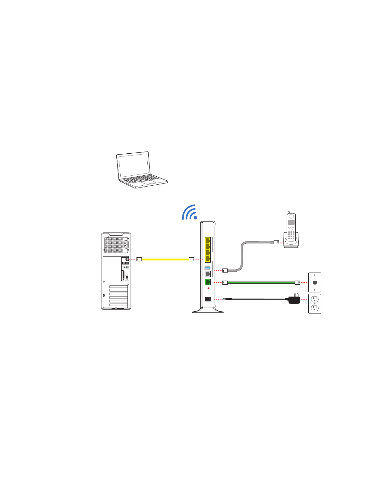
Installing the Gateway 2
Use the information in this chapter to connect the gateway to the Internet and to your
home network.
Wireless
connection
Phone
Phone cable
Phone cable
Power adapter
Ethernet cable
Wired
connection
4
3
ETHERNETETHERNET
21
HOME NETWORK
USB
PHONE
LINES 1 & 2
DSL
BROADBAND
RESET
POWER
To install the gateway, see the following:
1. “Installing DSL filters” on page 7
2. “Connecting the power adapter” on page 9
3. “Connecting the gateway to the Internet” on page 9
4. “Connecting computers to the gateway” on page 9
5. “Connecting phones” on page 11
6. “Configuring the gateway” on page 11
Phone
outlet
Power
outlet
6 Chapter 2 Installing the Gateway
Page 7

Installing DSL filters
DSL signals are carried over the same lines as regular phone signals. Converting your
regular phone line to DSL can cause high-pitched tones and static when you use the
phone. To eliminate the noise, you can install DSL filters on every phone or phone
device that shares the same phone number as your DSL.
You need one DSL filter for each phone device (such as a desktop phone, analog
modem, FAX, or answering machine). If you have several phone devices connected to
each other and are using a single phone jack, install only one DSL filter between the
phone jack and the first device in the series.
Note: Do not install a DSL filter on the line that is connected to the DSL gateway.
Installing a DSL inline filter
To use a filter with most phone devices, you must install the DSL filter between the
device and the phone jack.
1. Connect the cable from your device to the DSL filter.
2. Connect the cable from the DSL filter to your phone jack.
Chapter 2 Installing the Gateway 7
Page 8

Installing a DSL wall filter
To gateway
(optional)
To use a DSL filter with a wall-mounted phone, install the DSL filter between the
original wall plate and your wall-mounted phone.
1. Lift the phone from the wall pegs, and disconnect the phone cord from the phone
jack.
2. Connect the phone cord from the back of the DSL filter into the phone jack, and
mount the filter on the wall plate pegs using the keyhole slots.
3. Connect the phone cable to the phone jack located on the front of the mounted
DSL filter.
Note: Note: If you have a DSL modem, you can connect it to the DSL port at the
bottom of the filter.
4. Attach the phone to the mounting pegs on the DSL filter.
8 Chapter 2 Installing the Gateway
Page 9

Connecting the power adapter
The power adapter supplies power to the gateway. Always use the power adapter that
was packaged with the gateway because it matches the power requirements of the
gateway and it complies with local requirements.
1. Connect one end of the power adapter to the POWER port on the gateway.
2. Connect the cable’s other end to an electrical outlet.
After the gateway is powered on, the power light blinks green for a moment and then
turns steady green.
Connecting the gateway to the Internet
Connect the gateway to the Internet using the DSL Broadband port.
1. Connect one end of the green DSL cable to the green DSL Broadband port on the
gateway.
2. Connect the other end of the DSL cable to the wall jack.
After the gateway recognizes the connection, the Broadband light blinks green for a
moment and then turns steady green.
Connecting computers to the gateway
You can connect your computers and devices to the gateway using a wired
connection or a wireless connection. With either type of connection, you can use the
first computer that you connect to the network to set up the gateway.
Connecting devices using a wired connection
The gateway has four wired Ethernet ports that you can use to connect computers or
other devices.
1. Connect one end of the yellow Ethernet cable to one of the yellow Ethernet ports
on the gateway.
2. Connect the other end of the cable to the Ethernet port on the computer.
You can connect up to four computers to the gateway using the wired Ethernet ports.
Note: A 6-foot yellow Ethernet cable is provided with the gateway. If you need an
additional or longer cable, use a Cat 5 or Cat 5e Ethernet cable.
After the gateway recognizes the computer, the Ethernet light turns steady green, and
blinks when the computer starts transferring data with the gateway.
Chapter 2 Installing the Gateway 9
Page 10

Connecting devices using a wireless connection
label
The gateway has an integrated wireless access point that you can use to connect
wireless devices to the gateway. By default, the gateway is configured with a network
name (SSID) and WPA-PSK/WPA2-PSK security.
1. On the wireless device, view the available wireless networks. The specifics of how
you do this depend on the device you are connecting.
The default network name (SSID) and the encryption key (64-bit hex) is printed on
the label on the side of the gateway. Mac OS X users might have to enter the “$”
character at the beginning of the encryption key.
2. Select the appropriate network name and connect.
3. At the prompt, enter the encryption key.
After the gateway recognizes the wireless device, the WIRELESS light turns steady
green, and blinks when the wireless device starts transferring data with the gateway.
You can use WPS (Wi-Fi Protected Setup) to simplify the process of connecting
wireless devices to the network. For more information, go to the gateway configuration
page at http://192.168.1.254
10 Chapter 2 Installing the Gateway
Page 11

Connecting phones
The gateway includes one RJ-14 port (Phone 1 & 2) with the capacity to support 2
phone lines using a splitter or multi-jack adapter.
WARNING: Do not connect the VoIP lines to your current home telephone wiring,
especially if your home has an alarm system. Ensure that you are subscribed to VoIP
service before configuring VoIP on the gateway.
1. Connect one end of the phone cable to the gray Phone Lines 1 & 2 port on the
gateway.
2. Do one of the following:
• For one phone, connect the phone cable directly to the telephone.
• For two phones, connect the phone cable to a splitter and then to the
telephones.
4
3
ETHERNETETHERNET
21
HOME NETWORK
PHONE
LINES 1 & 2
DSL
BROADBAND
RESET
POWER
4
3
ETHERNETETHERNET
21
HOME NETWORK
PHONE
LINES 1 & 2
DSL
BROADBAND
RESET
POWER
After the gateway recognizes the phones (Line 1 and Line 2), the Phone 1 and
Phone 2 lights turn steady green and blink when the associated phone is active.
Configuring the gateway
If necessary, you can use the gateway configuration page to view or change the
gateway settings.
On a computer connected to the gateway, enter the following into the address bar of a
Web browser:
• http://192.168.1.254
You can also use http://gateway.pace.net to access the gateway configuration page.
Chapter 2 Installing the Gateway 11
Page 12

Troubleshooting 3
This chapter provides information about common gateway installation issues. If an
issue has more than one potential cause, the most common cause is listed first.
Connection issues
Use the information in this section to identify and resolve issues related to
connectivity.
The Power light is not on
• The power cable may be loose or disconnected. Check the power cable to ensure
that the cable is securely connected. If the power cable is plugged in to a power
strip or switched outlet, ensure that it is on. Ensure that you are using the power
supply that came with the gateway.
• The power supply may be faulty. Verify that the light on the power supply is green.
• The AC outlet may be faulty. Try plugging the gateway in to a known good outlet.
The Power light blinks immediately after the device starts, and then turns steady
green
• The Power light blinks during POST (Power on self-test). This is normal behavior.
The Power light is red
• The POST (Power on self-test) may have failed. Press the Reset button and hold it
for 10 seconds to reset the gateway.
The Broadband light blinks
• The Ethernet or DSL cable may be loose or disconnected. Check the connections
to ensure that the cable is securely connected.
• The DSL connection may not be established. Press the Reset button and hold it
for 10 seconds to reset the gateway. If resetting the gateway does not fix the
problem, contact your service provider.
The Broadband light blinks green for a long time, then turns red
• The gateway may have failed to synchronize with the service provider network.
Check the connections to ensure that the cable is securely connected.
• Your Internet service may not be activated. Contact your service provider.
12 Chapter 3 Troubleshooting
Page 13

The Service light blinks
• Your Internet service may not be activated. Contact your service provider.
The Service light is red
• The user name and password may have been entered incorrectly. Verify the user
name and password on the gateway configuration page, and try again.
• Your Internet service may not be activated. Contact your service provider.
The Ethernet light is not on
• The Ethernet cable may be loose or disconnected. Check the connections to
ensure that the cable is securely connected.
The Wireless light is not on
• No devices on your home network are currently connected to the gateway over the
wireless connection.
• Ensure that the wireless feature is enabled. For more information, go to the
gateway configuration page at http://192.168.1.254
The Internet is not accessible but the gateway configuration page is accessible
• The Ethernet or DSL cable may be loose or disconnected. Check the connections
to ensure that the cable is securely connected.
LAN issues
Use the information in this section to identify and resolve issues related to the home
network.
Can’t connect to the gateway through the Ethernet port
• The Ethernet cable may be loose or disconnected. Check the connections to
ensure that the cable is securely connected. The Ethernet light blinks green when
there is a working link to a device.
A wireless device cannot get an IP address
• The device may not be set up with the appropriate security type or security key.
Ensure that the wireless device is using the appropriate credentials.
• The wireless device and the gateway may be using different wireless modes, such
as 802.11b, 802.11g, or 802.11n. Ensure that the wireless device and the gateway
are using compatible modes.
The wireless signal is weak
• The wireless device may be out of range. Ensure that the wireless device is within
the range of the gateway.
Chapter 3 Troubleshooting 13
Page 14

I cannot set a custom encryption key on the gateway user interface
• The custom encryption key may not conform with the security mode, key length,
key type, or value type. Configure the custom encryption key so that it conforms to
the security mode, key length, key type, or value type.
Voice issues
Use the information in this section to identify and resolve common issues related to
VoIP (Voice over Internet Protocol).
The Phone 1 and Phone 2 lights are not on
• The data cable may be loose or disconnected. Check the connections to ensure
that the cable is securely connected.
• The lines or SIP server may be configured incorrectly. For more information, see
the HomePortal Intelligent Gateway User Guide.
No dial tone
• The service may be down or not activated. Verify that the phone is in Active mode.
If the issue persists, contact your service provider.
14 Chapter 3 Troubleshooting
Page 15

Status lights
Use the status lights on the front of the gateway to determine the current state of the
gateway.
Status light Description
Power • Solid green. Power is on.
• Red. The gateway is faulty.
Ethernet • Solid green. A computer or other device is
connected to an ETHERNET port.
• Flickering green. There is activity from devices
connected to an Ethernet port. The flickering of the
light is synchronized to actual data traffic.
Wireless • Solid green. A wireless computer or other device is
connected.
• Flickering green. There is inbound or outbound
activity. The flickering of the light is synchronized to
actual data traffic.
Phone 1 and 2 • Solid green. A phone is connected.
• Flashing green. The associated phone is active.
USB • Solid green. A device is connected to the USB port.
• Flashing green. The USB device is active.
Broadband • Solid green. The gateway is connected to the
service provider network.
• Flashing green. The gateway is attempting to
establish a connection to the service provider
network.
• Red. There is no DSL signal.
Service • Solid green. The gateway has obtained a WAN IP
address from the service provider through the
DHCP or PPP connection and the broadband
connection is up.
• Fast flashing green. The gateway is attempting to
obtain an IP address.
• Slow flashing green. The service provider network
is not responding, the gateway has been configured
incorrectly, or there was an authentication failure.
Chapter 3 Troubleshooting 15
Page 16

Regulatory Information A
Declaration of conformity
The following sections describe regulatory compliance by region.
FCC/Industry Canada compliance
This device has been tested and certified as compliant with the regulations and
guidelines set forth in the Federal Communication commission - FCC part 15, FCC
part 68 and Industry Canada - ICES003 and RSS-210 Radio and telecommunication
regulatory requirements.
Le présent materiel est conforme aux specifications techniques applicables d'Industrie
Canada. Cet appareil numérique de la classe [*] est conforme à la norme NMB-003 du
Canada.
Manufacturer: 2Wire, Inc. DBA Pace Americas
Model(s): 5111NV
Part 15 of FCC rules
This device complies with part 15 of the FCC Rules and Industry Canada licenseexempt RSS standard(s). Operation is subject to the following two conditions:
(1) this device may not cause harmful interference, and
(2) this device must accept any interference received, including interference that may
cause undesired operation of the device.
Le présent appareil est conforme aux normes CNR d'Industrie Canada applicables
aux appareils radio exempts de licence. L'exploitation est autorisée aux deux
conditions suivantes:
(1) l'appareil ne doit pas produire de brouillage, et
(2) l'utilisateur de l'appareil doit accepter tout brouillage radioélectrique subi, même si
le brouillage est susceptible d'en compromettre le fonctionnement.
This equipment has been tested and found to comply with the limits for a Class B
digital device, pursuant to part 15 of the FCC Rules. These limits are designed to
provide reasonable protection against harmful interference in a residential installation.
This equipment generates uses and can radiate radio frequency energy and, if not
installed and used in accordance with the instructions, may cause harmful
interference to radio communications. However, there is no guarantee that
16 Appendix A Regulatory Information
Page 17

interference will not occur in a particular installation. If this equipment does cause
harmful interference to radio or television reception, which can be determined by
turning the equipment off and on, the user is encouraged to try to correct the
interference by one or more of the following measures:
• Reorient or relocate the receiving antenna.
• Increase the separation between the equipment and receiver.
• Connect the equipment into an outlet on a circuit different from that to which the
receiver is connected.
• Consult the dealer or an experienced radio/TV technician for help.
Caution: Changes or modifications not expressly approved by the party responsible
for compliance could void your authority to operate this equipment.
TIA 968 (Part 68 of FCC rules)/IC CS-03
This equipment complies with the Telecommunication Industry Association TIA-968
(FCC part 68) and Industry Canada CS-03 Telecommunication requirements. On the
product is a label that contains, among other information, the IC and FCC registration
number and ringer equivalence number (REN) for this equipment. If requested, this
information may be provided to the telephone company.
The REN is used to determine the quantity of devices that may be connected to the
telephone line. Excessive RENs on the telephone line may result in the device not
ringing in response to an incoming call. In most, but not all areas, the sum of the
RENs should not exceed five (5.0)
L'indice d'équivalence de la sonnerie (IES) sert à indiquer le nombre maximal de
terminaux qui peuvent être raccordés à une interface téléphonique. La terminaison
d'une interface peut consister en une combinaison quelconque de dispositifs, à la
seule condition que la somme d'indices d'équivalence de la sonnerie de tous les
dispositifs n'excède pas 5.
To be certain of the number of devices that may be connected to the line, as
determined by the total RENs, contact the telephone company to determine the
maximum RENs for the calling area.
This product cannot be used on telephone-company-provided coin service.
Connection to Party Line Service is subject to state tariffs.
An FCC-compliant telephone cord and modular plug is provided with this equipment.
This equipment is designed to be connected to the telephone network or premises
wiring using a compatible modular jack that is Part 68 compliant. If this equipment
causes harm to the telephone network, the telephone company will notify you in
advance that temporary discontinuance of service may be required. If advance notice
is not practical, the telephone company will notify the customer as soon as possible.
Also, you will be advised of your right to file a complaint with the FCC if you believe it
is necessary. The telephone company may make changes in its facilities, equipment,
operations, or procedures that could affect the operation of this equipment. If this
happens, the telephone company will provide advance notice in order for you to make
Appendix A Regulatory Information 17
Page 18

the necessary modifications to maintain uninterrupted service. If trouble is
experienced with this equipment, please contact Pace Americas, or your local Pace
Americas distributor or service center in the U.S.A. for repair and/or warrant
information. If the trouble is causing harm to the telephone network, the telephone
company may request you to remove this equipment from the network until the
problem is resolved. No repairs can be done by a customer on this equipment. It is
recommended that the customer install an AC surge arrestor in the AC outlet to which
this device is connected. This is to avoid damage to the equipment caused by local
lightning strikes and other electrical surges.
MPE/SAR/RF exposure information
This device was verified for RF exposure and found to comply with Council
Recommendation 1999/519/EC and FCC OET-65 RF exposure requirements. This
equipment complies with FCC radiation exposure limits set forth for an uncontrolled
environment.
WARNING: While this device is in operation, a separation distance of at least 20 cm
(8 inches) must be maintained between the radiating antenna inside the EUT and the
bodies of all persons exposed to the transmitter in order to meet the FCC RF
exposure guidelines. Making changes to the antenna or the device is not permitted.
Doing so may result in the installed system exceeding RF exposure requirements.
This device must not be co-located or operated in conjunction with any other antenna
or radio transmitter.
Safety information
The following sections describe the safety guidelines for this product.
AC adapter
This product is intended to be supplied with a listed Pace Direct Plug-In AC/DC power
adapter marked Class 2 or LPS and rated 12V 3A for all 5111NV-xxx models.
The AC/DC power adapter supplied with this product is designed to ensure your
personal safety and to be compatible with this equipment. Use only the power adapter
that was provided with the gateway.
18 Appendix A Regulatory Information
Page 19

Please follow these guidelines:
• Do not use the adapter in a high moisture environment. Never touch the adapter
when your hands or feet are wet.
• Allow adequate ventilation around the adapter. Avoid locations with restricted
airflow.
• Connect the adapter to a proper power source. The voltage and grounding
requirements are found on the product case and/or packaging.
• Do not use the adapter if the cord becomes damaged.
• Do not attempt to service the adapter. There are no serviceable parts inside.
Replace the unit if it is damaged or exposed to excess moisture.
Telecommunication cord
Caution: To reduce the risk of fire, use only No. 26 AWG or larger UL Listed or CSA
Certified Telecommunication Line Cord.
Internal Telephone ports (VoIP)
Telecommunication equipment connected to this port (e.g., via “Phone Lines 1 & 2”
port) should be UL Listed and the connections shall be made in accordance with
Article 800 of the NEC.
Repairs
Do not, under any circumstances, attempt any service, adjustments, or repairs on this
equipment. Instead, contact your local Pace Americas distributor or service provider
for assistance. Failure to comply may void the product warranty.
Location - electrical considerations
CAUTION: Due to risk of electrical shock or damage, do not use this product near
water, including a bathtub, wash bowl, kitchen sink or laundry tub, in a wet basement,
or near a swimming pool. Also, avoid using this product during electrical storms. Avoid
locations near electrical appliances or other devices that cause excessive voltage
fluctuations or emit electrical noise (for example, air conditioners, neon signs, highfrequency or magnetic security devices, or electric motors).
Location - environmental considerations
Do not plug the AC/DC power adapter into an outdoor outlet or operate the residential
gateway outdoors. It is not waterproof or dustproof, and is for indoor use only. Any
damage to the unit from exposure to rain or dust may void your warranty.
Do not use the residential gateway where there is high heat, dust, humidity, moisture,
or caustic chemicals or oils. Keep the gateway away from direct sunlight and anything
that radiates heat, such as a stove or a motor.
Appendix A Regulatory Information 19
 Loading...