How it Works
Log In / Sign Up
Buy Points
How it Works
FAQ
Contact Us
Questions and Suggestions
Users
ARISTON
Loading...
N
NEW GENUS EST 23 MFFI
NEW GENUS EST 23 MI
NEW STORAGE
NEXT EVO SFT 11 NG EXP
NEXT EVO X OUTDOOR 11 LPG EU Orizzontale Boiler Sistema per caldaia singola Bianco
NEXT EVO X OUTDOOR 11 NG EU Orizzontale Boiler Sistema per caldaia singola Bianco
NEXT EVO X OUTDOOR 16 LPG EU Orizzontale Boiler Sistema per caldaia singola Bianco
NHRE 18
NHRE26-60
NHRE 75-90
NIA 640 B
10
NIA 640 NE
4
NIC 641 B
4
NID 641 B C
4
NIO 632 CP CAUS
NIO 844 DO B AUS S
NIS 642 FB AUS
NIS 741 F C
4
NIS 841 F B AUS
12
NIS 952 FB AUS
NIU 642 F C
4
NLLCD 1045 SC A 60hz
2
NLLCD 1165 SC AD EX
3
NLLCD 1165 SC AD GCC
2
NLM11 946 SC A 60hz
2
NLM11 946 SC A EX
3
NLM11 946 SC A GCC
2
NLM11 946 SS A MA
3
NLM11 946 WC A EX
3
NLM11 946 WC A GCC
2
NM10 723 SS 60hz
2
NM10 723 SS EX
3
NM10 723 SS GCC
2
NM10 723 WS EX
3
NM10 723 WS GCC
2
NM10 823 SS 60hz
2
NM10 823 SS EX
3
NM10 823 SS MA
3
NM10 823 WS 60hz
2
NM10 823 WS EX
3
NMBL1922CVW-HA
NMTM1912
NMTM 1921 FW-HA
NMTM1921VWB-HA
NMTM1922FWB
NMTM1923FW-HA
2
NMTP 1912 F-HA
NRA 640 C AUS
NRA 640 X
2
NRB640C
NRC 641 D B
2
NRM 640 X
NRO841OX
NS 703U W EX
2
NS 703U W GCC
2
NS 703U W MA
3
NS 723U GG EX
2
NT CM10 8BS EX
3
NT CM10 8BSK 60Hz
2
NT CM10 8BSK AG
NT M10 81 EX
3
NT M11 9X1SXB EX
3
NTS 100 V SUPERLUX REGENT
NTS 80V 1
NUOS
4
NUOS 200-250
Nuos Evo A+ 100 Verticale Boiler Sistema di caldaia combinato Bianco
Nuos Evo A+ Verticale Boiler Sistema per caldaia singola Bianco
Nuos Plus S2 WH 3629145 80 l Pompa ciepła
Nuos Plus S2 WH 3629146 110 l Pompa ciepła
Nuos Plus S2 WH 3629147 150 l Pompa ciepła
Nuos Split
NUOS SPLIT FLEX
NUP1811
O
OK 1035 EL D.20 -HA
OK 1035 EL D.20 X -HA
OK 1035 EN D.20 -HA
OK 1035 EN D.20 X -HA
OK 1037 EL D.20 -HA
OK 1037 EL D.20 X-HA
OK 1037EL DP.20 X-HA
OK 1037EN D.20 X-HA
OK 892EL P AUS S
OK 892EL P X AUS S
OK 892EL S P AUS
OK 892EL S P X AUS
OK 897E LC AUS
OK 897E LC X AUS
OK 897E LSC AUS
OK 897E LSC X AUS
OK 89E D X 60 HZ S
OK 997E LDP AUS S
OK 997E LDP X AUS S
OK 999E LDP AUS S
OK 999E LDP X AUS S
OK 999EL S D P AUS
OK 999EL S D P X AUS
OK RF 3100 NFL
ON 538 I RFH
ON 837 I RFH
Loading...
Loading...
Nothing found
NRC 641 D B
User Manual
56 pgs
2.49 Mb
0
User Manual
52 pgs
2.63 Mb
0
Table of contents
Loading...
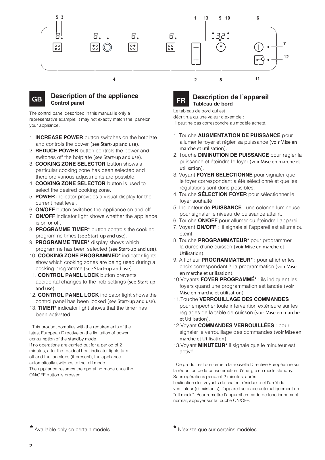
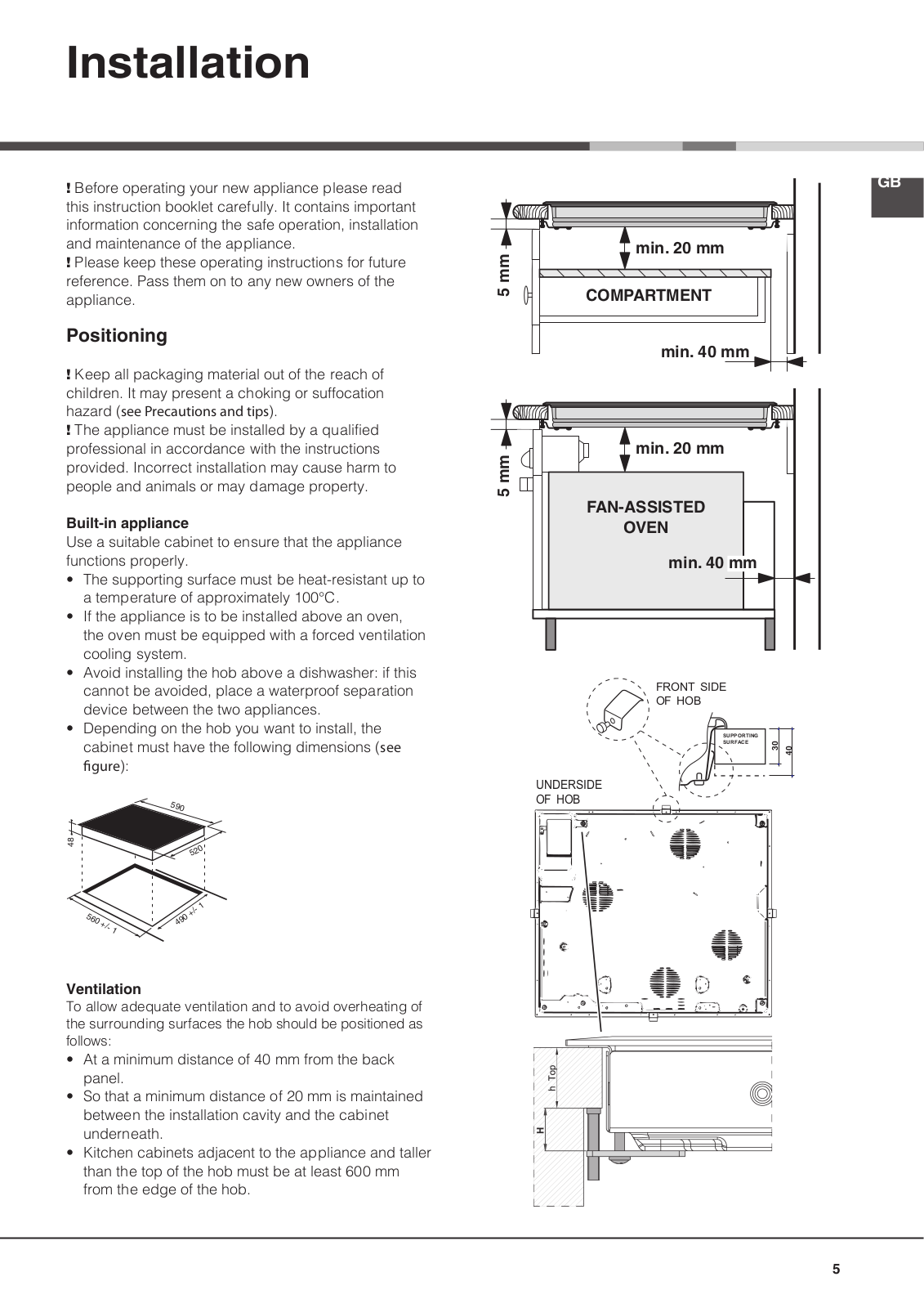
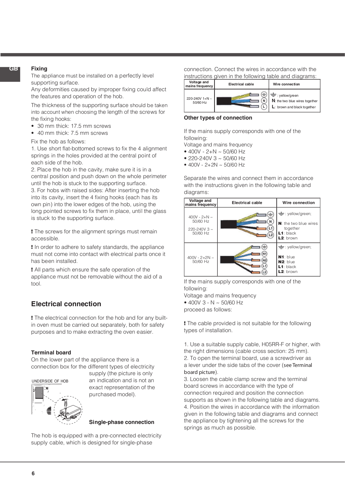
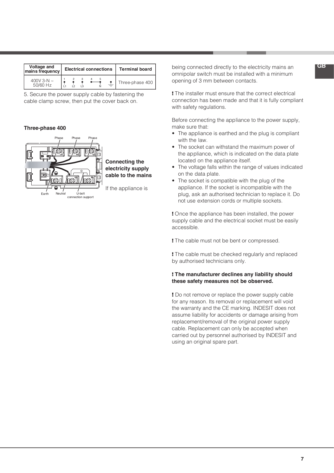
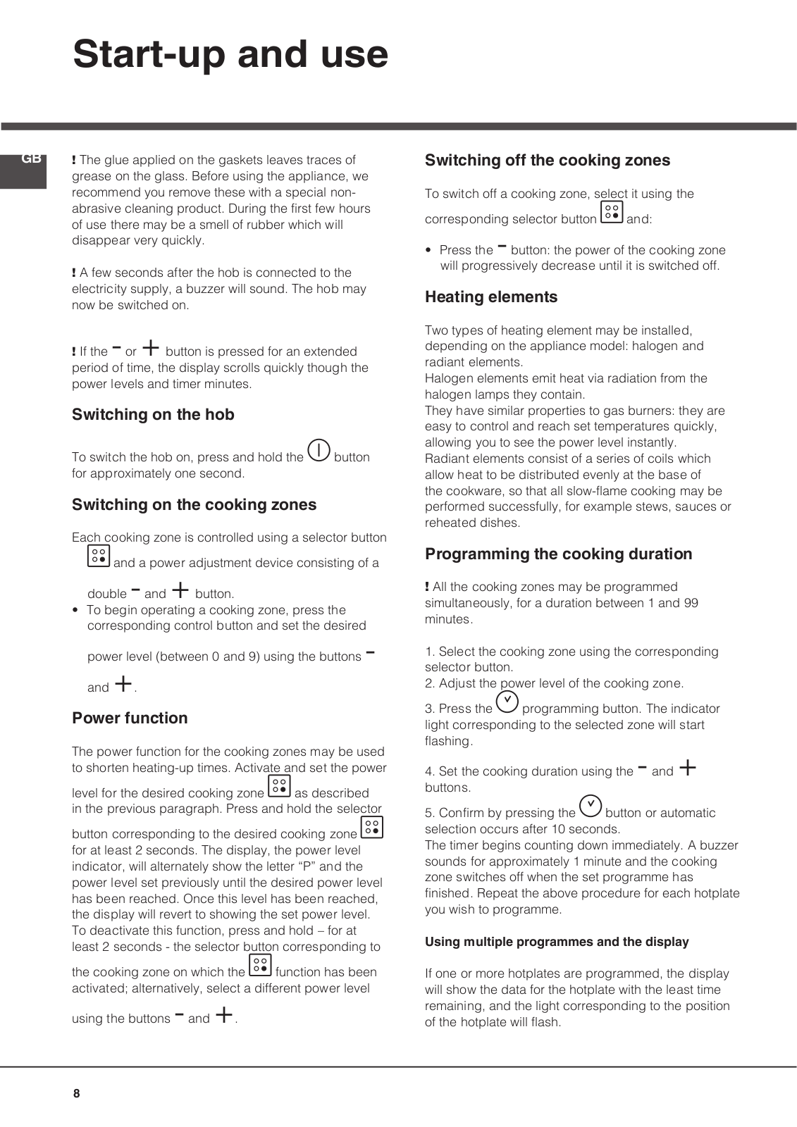
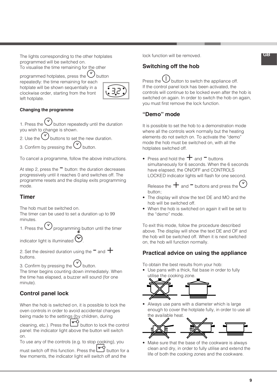
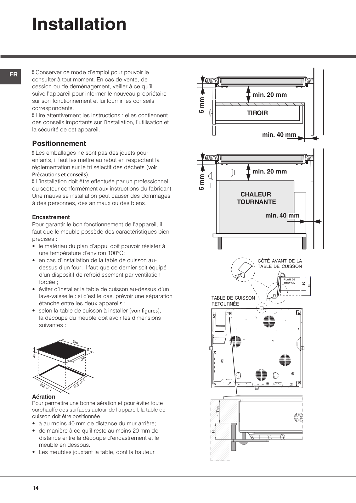
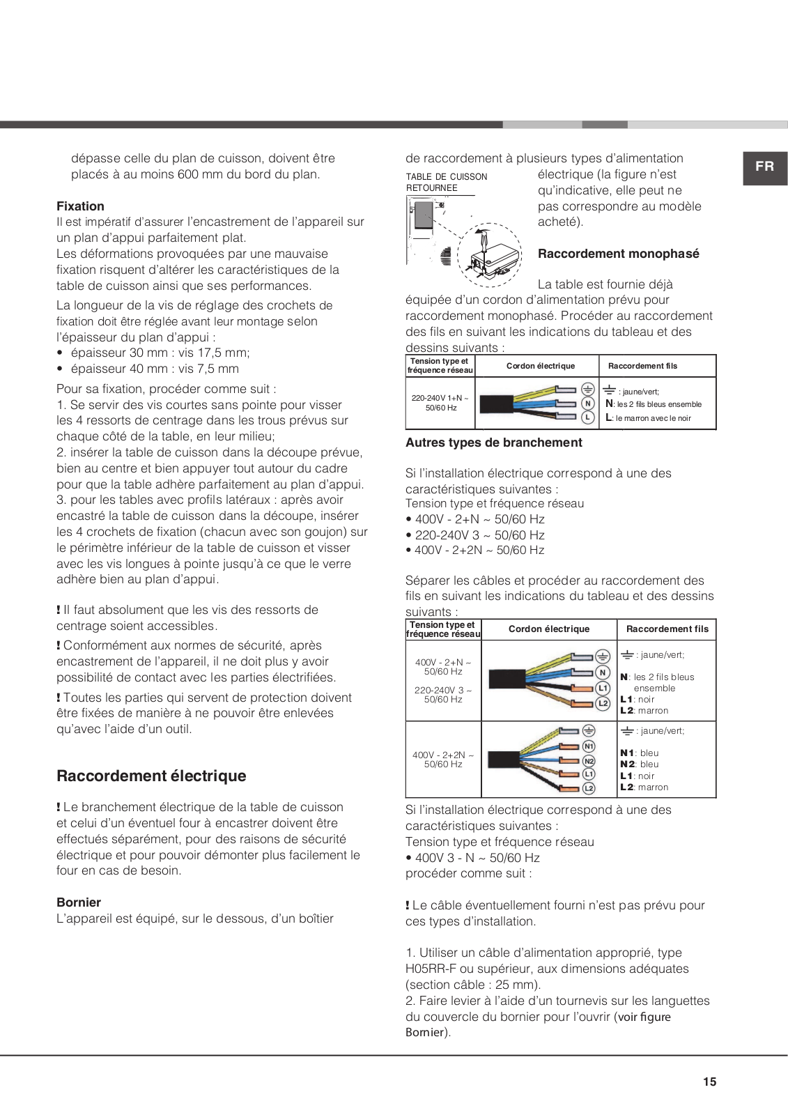
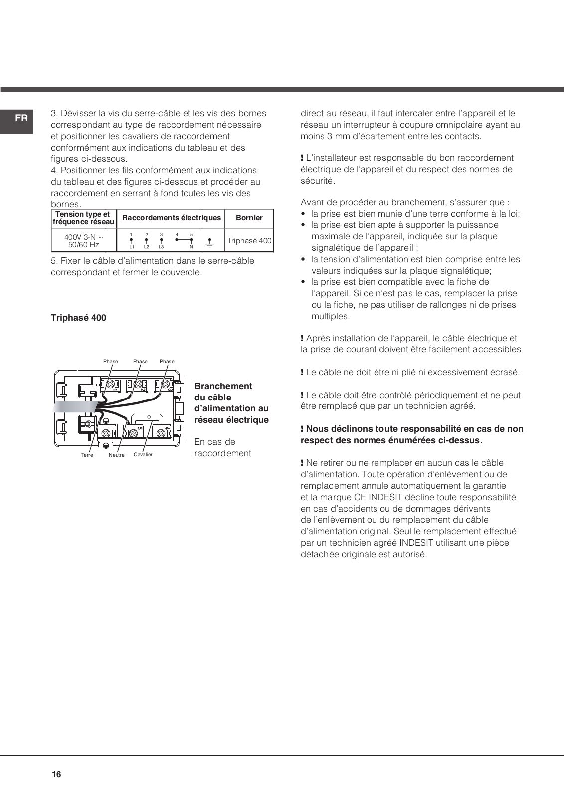
ARISTON NRC 641 D B User Manual
...
ARISTON User Manual
Download
Specifications and Main Features
Frequently Asked Questions
User Manual
Download
Loading...
+
hidden pages
Unhide
You need points to download manuals.
1 point = 1 manual.
You can buy points or you can get point for every manual you upload.
Buy points
Upload your manuals
 Loading...